1
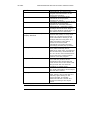
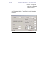
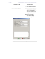
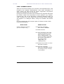
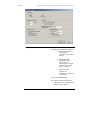
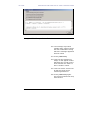
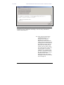
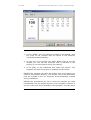
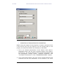
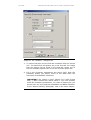
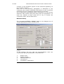
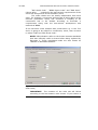
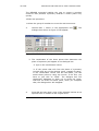
VK STEEL
DESCRIPTION AND ANALYSIS OF STEEL CONSTRUCTIONS
We enter the maximum width of the weld between the
column and its end plate in mm
12.
Allowable stress of welding σw (Mpa)
We set the allowable stress of the weld between the
column and its end plate in Mpa.
13.
Allowable shear stress of welding τw (Mpa)
We set the allowable stress of the weld, between the
column and its end plate, in shear, in Mpa.
14.
Allowable equivalent stress of welding σvw (Mpa)
15.
Allowable stress of anchorage bolts (Mpa)
We enter the anchorage bolts’, which hold the plate on the
reinforced concrete footing, allowable stress in Mpa.
16.
Anchorage bolt’s diameter (mm)
We set the anchorage bolt’s desirable diameter (a bolt’s
diameter is equal to its bore’s diameter 20 mm suggested
minimum diameter.
17.
Area of Anchorage bolt section (cm²)
Set the anchorage bolt’s core section area
18.
Minimum distance of anchorage bolt from the edge
L= k x danch k = …
Set the anchorage bolt’s minimum distance from the edge
of the plate which equals the K factor multiplied by the
anchorage bolt’s diameter. Set K factor’s value.
19.
Minimum distance between anchorage bolts a = k x d
anch k= …
Set the minimum distance between bolts. This distance is
equal to the K factor multiplied by the anchorage bolt’s
diameter. Set K factor’s value.
20.
Maximum number of anchorage bolts.
Set the maximum number of anchorage bolts that you wish
to place on the plate. The programme can take up to 50
anchorage bolts.
21.
Allowable stress of concrete – steel interrelation
(Mpa)
188
CHAPTER 8 COLUMN BASE DESIGN
FOUNDATION DESIGN