1
User’s Manual
DAS-8000
Ver 2.5
DAS-8000 ver. 2.5
User’s Manual / 2
DAS-8000 ver. 2.5
Contents
USER’S MANUAL ....................................................................................... 1
CONTENTS ............................................................................................................... 3
INTRODUCTION ........................................................................................ 7
GENERAL DESCRIPTION ............................................................................................ 9
VERSIONS .............................................................................................................. 11
IMPROVEMENTS AND ADDED FEATURES IN VERSION 2.5 ............................................................. 12
DAS-8000 VER 2.1 ........................................................................................................................ 13
IMPROVEMENTS AND ADDED FEATURES IN VERSION 2.0 ............................................................. 13
HOW THIS MANUAL IS ORGANIZED ................................................................................................ 14
CONTENTS OF THE BOX .......................................................................................... 16
Standard versions...................................................................................................................... 16
EK Evaluation Kit .................................................................................................................... 18
PRESET CONFIGURATION ....................................................................................... 20
INSTALLATION ........................................................................................ 23
PRECAUTIONS ........................................................................................................ 25
PRECAUTIONS IN THE ASSEMBLY AREA ....................................................................................... 25
PRECAUTIONS WHEN CONNECTING EQUIPMENT ........................................................................... 26
Connecting to the Main Power. ................................................................................................ 26
Connecting the transducer input. .............................................................................................. 27
Connection to Ground............................................................................................................... 28
Digital serial communication. .................................................................................................. 28
GENERAL PRECAUTIONS ................................................................................................................ 29
ASSEMBLY............................................................................................................. 30
ASSEMBLY TYPES .......................................................................................................................... 30
DIMENSION AND OPENINGS IN PANEL............................................................................................ 35
CONNECTIONS. ...................................................................................................... 36
ANALOG INPUT CONNECTIONS ....................................................................................................... 36
ANALOG INPUTS MA. USING THE SAME POWER SUPPLY .............................................................. 37
Example using independent power supply ............................................................................... 37
Example using same power supply........................................................................................... 37
DIGITAL INPUT CONNECTIONS ....................................................................................................... 38
DIGITAL OUTPUT CONNECTIONS .................................................................................................... 39
EXAMPLES OF CONNECTIONS ........................................................................................................ 40
COMMUNICATIONS ......................................................................................................................... 43
RS-232 connection.................................................................................................................... 43
RS-232 connection to serial printer.......................................................................................... 43
RS-485 connection.................................................................................................................... 43
COMMUNICATIONS ARCHITECTURE............................................................................................... 44
DESCRIPTION........................................................................................... 47
FRONT PANEL DESCRIPTION.................................................................................... 49
User’s Manual / 3
DAS-8000 ver. 2.5
DISPLAY ......................................................................................................................................... 49
KEYBOARD ..................................................................................................................................... 50
CONNECTION TERMINALS .............................................................................................................. 51
INSIDE ................................................................................................................... 52
HOW TO OPEN IT............................................................................................................................. 53
ANALOG INPUT CONFIGURATION “JUMPERS”. .............................................................................. 54
CONFIGURATION STRAPS AND “JUMPER” ..................................................................................... 55
Configuration of communication type...................................................................................... 56
Communication speed setup ..................................................................................................... 56
INSTRUCTIONS FOR USE....................................................................... 57
MENU TREE ........................................................................................................... 59
DISPLAY MENU............................................................................................................................... 59
CONFIGURATION MENU ................................................................................................................. 62
DESCRIPTION OF DISPLAY MENU PARAMETERS ....................................................... 65
DISPLAYING THE SOFTWARE VERSION .......................................................................................... 65
MANUAL DISPLAY OF MODULE MEASUREMENTS. ........................................................................ 66
AUTOMATIC DISPLAY OF MODULE MEASUREMENTS.................................................................... 66
MANUAL DISPLAY OF THE MEASUREMENTS OF OTHER MODULES. ............................................. 67
AUTOMATIC DISPLAY OF MEASUREMENTS OF OTHER MODULES................................................. 69
ALARM DATA DISPLAY................................................................................................................... 69
Manual alarm acknowledgment. .............................................................................................. 70
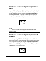
How to see and/or modify the setpoint of an alarm.................................................................. 72
How to see and/or modify the hysteresis of an alarm............................................................... 72
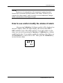
How to see and/or modify the status of alarm .......................................................................... 73
COUNTER OPERATION CRITERIA ............................................................................. 74
COUNTER DISPLAY ........................................................................................................................ 76
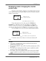
Displaying and/or changing the counter preset value .............................................................. 77
PERFORMING A COUNTER RESET .................................................................................................. 78
PRINTING MEASUREMENTS OF DAS-8000 MODULES ............................................... 79
AUTOMATIC MODE ......................................................................................................................... 79
MANUAL MODE .............................................................................................................................. 79
Dumping data to printer from other network modules............................................................. 80
PRINTING DAS-8000 MODULE ALARMS .................................................................. 82
ALARM PRINTING ........................................................................................................................... 82
CONFIGURATION .................................................................................... 85
DESCRIPTION OF CONFIGURATION MENU PARAMETERS........................................... 87
PASSWORD INPUT .......................................................................................................................... 87
ALARM PARAMETERS .................................................................................................................... 88
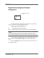
Disabling the Alarm Output. Digital Input Assignment. ......................................................... 89
Assignment of Digital Output................................................................................................... 90
Assignment of Analog Channel. ............................................................................................... 91
Selection of Alarm type. ........................................................................................................... 92
DELAY OF ALARM CONNECTION................................................................................................... 95
ALARM ACKNOWLEDGMENT PARAMETERS ................................................................................. 96
ALARM ACKNOWLEDGEMENT SETUP ........................................................................................... 96
Digital Acknowledgement Input Assignment. ......................................................................... 97
Digital Acknowledgement Output Assignment........................................................................ 98
TEMPERATURE UNIT SETUP .......................................................................................................... 99
User’s Manual / 4
DAS-8000 ver. 2.5
ANALOG CHANNEL PARAMETERS ............................................................................................... 100
Peak filter and range Oveflow display ................................................................................... 101
Average filter .......................................................................................................................... 102
Selection of Sensor Type ........................................................................................................ 102
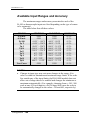
Available Input Ranges and Accuracy ................................................................................... 104
User curve setup...................................................................................................................... 105
Number of Decimals Points Selection.................................................................................... 106
Low and High ranges.............................................................................................................. 106
Indication Offset ..................................................................................................................... 107
DIGITAL OUTPUT PARAMETERS................................................................................................... 108
Digital Output type................................................................................................................. 109
Security Status ........................................................................................................................ 110
Active security ........................................................................................................................ 111
Initial Status on startup........................................................................................................... 112
Digital Output inversion......................................................................................................... 113
LOCAL ALARM DIAGRAM ............................................................................................................ 114
REMOTE ACTION DIAGRAM ......................................................................................................... 115
COMMUNICATIONS PARAMETERS................................................................................................ 116
Communications address ........................................................................................................ 116
Communications speed ........................................................................................................... 117
Communication test ................................................................................................................ 117
COUNTER PARAMETERS............................................................................................................... 118
Counter setup .......................................................................................................................... 119
MONITORING PARAMETER ........................................................................................................... 121
REPORT PRINTING PARAMETERS ................................................................................................. 121
Printing Periodicity ................................................................................................................. 122
Selection of Modules to Print ................................................................................................. 122
Printer Communications parameters ...................................................................................... 123
Alarm or Measurement Printing Parameters.......................................................................... 125
Assignment of Digital Input for Measurement Remote Printing ........................................... 125
Alarm Printing Activation. ..................................................................................................... 126
DISPLAY TEST............................................................................................................................... 127
CHANGE OF GENERAL PASSWORD .............................................................................................. 128
CHANGE OF PASSWORD ALARM PARAMETERS........................................................................... 129
SUMMARY OF CONFIGURATION PARAMETERS ........................................................................... 130
CALIBRATION........................................................................................ 133
CALIBRATION PROCEDURE ................................................................................... 135
PT-100 INPUT ............................................................................................................................... 136
4-20 MA (OR 0-20 MA) MILLIAMPS INPUT.................................................................................. 138
MILLIVOLT (MV) INPUT ............................................................................................................... 140
SMALL ERRORS CORRECTION “OFFSET”..................................................................................... 141
HOW TO RECOVER THE ORIGINAL CALIBRATION ......................................................................... 142
COMMUNICATIONS .............................................................................. 143
COMMUNICATIONS DESCRIPTION .......................................................................... 145
NUMBERING THE MODULES .................................................................................. 147
TYPES OF COMMUNICATIONS................................................................................ 148
RS-485 COMMUNICATIONS WITH A NETWORK OF DAS-8000 .................................................... 148
Wiring diagram....................................................................................................................... 149
User’s Manual / 5
DAS-8000 ver. 2.5
RS-232 COMMUNICATIONS WITH A PC........................................................................................ 150
Wiring diagram....................................................................................................................... 150
RS-485 COMMUNICATIONS WITH A PC ....................................................................................... 152
Wiring diagram in RS-485 ..................................................................................................... 154
RS-232 PRINTER COMMUNICATIONS .......................................................................................... 155
Wiring diagram....................................................................................................................... 155
COMMUNICATION PROTOCOLS ............................................................................. 156
ESTRUCTURE OF THE MESSAGES ................................................................................................. 156
Calculation of CRC-16........................................................................................................... 158
CRC-16 calculation example ................................................................................................. 158
LIST OF WORDS............................................................................................................................. 159
Input Area (Reading only)...................................................................................................... 160
Output area (Read and/or Written)......................................................................................... 161
MAINTENANCE ...................................................................................... 165
DISPLAY MESSAGES CODES ................................................................................... 167
LOCATING FAILURES ............................................................................................ 168
MAINTENANCE..................................................................................................... 169
SPARE PARTS. ...................................................................................................... 170
APPENDIX 1.- HEXADECIMAL CODE ..................................................................... 171
APPENDIX 2.- TECHNICAL SPECIFICATIONS ........................................................... 173
Notes: ...................................................................................................................................... 175
User’s Manual / 6
DAS-8000 ver. 2.5
Introduction
Introduction / 7
DAS-8000 ver. 2.5
Introduction / 8
DAS-8000 ver. 2.5
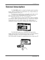
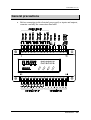
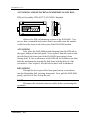
General description
The DAS-8000 module is a digital and analog signal acquisition
device, which can function in an autonomous way, or supervised by an
intelligent system (PC, PLC, etc.).
It accepts up to 8 analog inputs configurable for Pt-100, 0..4-20
mA., 0..10-50 mV and 8 thermocouples for 4-20 mA. Inputs from
non- linearized converters, (E, J, K, T, S, R, B and N).
It has 8 digital inputs to capture logical data (Alarm recognition
push-buttons, contacts, proximity detectors, etc.), and also has 8 digital
outputs, that can be used as alarm outputs of the analog inputs, or
controlled via remote control by communication with the central unit.
The DAS-8000 module has a detachable front panel with a
display and keyboard for monitoring measurements. It can also function
without the front panel, and is able to display data from other
DAS-8000 modules, through the communications bus or supervisory PC.
Introduction / 9
DAS-8000 ver. 2.5
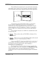
This multifunction terminal can be removed from the main body,
which allows you to mount it in the front panel, placing the main block
of the DAS-8000 on the back as endpoint connection of the signal lines.
Communication among DAS-8000 modules is performed in
RS-485 protocol, enabling the connection of a maximum of 32
instruments in the same communications line (it can reach 255 units
using preamplifiers or RS-485 multiplexes). Thereby, it is possible to
achieve a high level of immunity from electrical noise and industrial
parasites.
One selectable serial port are available for communications with
the Supervisory PC:
• RS-232 When you have only one DAS-8000 at a distance of less
than 15 meters.
• RS-485 If there are two or more DAS-8000 modules in the network
at a distance of over 15 meters (maximum 1200 m.).
It has a second RS-232 channel specifically for the connection of
a serial printer. Data and measurements in tabular format are sent via
this channel to generate printed reports, either manually or
automatically, at a predefined time.
The management of the data and measurement acquired by the
DAS-8000 modules, from a PC, is handled by the PROASIS DAS-Win
software program, that is a SCADA application under Windows,
composed of a series of supervision and control programs for industrial
processes.
Introduction / 10
DAS-8000 ver. 2.5
Versions
Basically, there are 2 versions:
• DAS-8000 . Version with removable terminal (display and
keyboard). It includes PROASIS DAS-Win data management
software.
• DAS-8000 /ND . Version without front panel terminal.
It also includes the PROASIS DAS-Win. management software.
It exists also two sets equipped with different elements:
• DAS-8000 /KE. EVALUATION KIT Version.
This version includes all required items to make a system operational
in a just a few minutes in order to evaluate all its features. The kit
also includes the PROASIS DAS-Win software preconfigured.
•
DAS-8000/DEMO KIT. DEMO version.
The specific suitcase apart the DAS-8000 module it includes different
probes, 4-20 mA transmitters, light indicators, acoustical, etc. for a
practical demonstration of DAS-8000 possibilities. Also includes the
preconfigured PROASIS DAS-Win software suite.
Introduction / 11
DAS-8000 ver. 2.5
Improvements and added features in version 2.5
As a general features to highlight in version 2.5 in relation to 2.1 version
these are as follows:
•
•
•
•
•
•
•
Display controlled by new microprocessor that allows to achieve until 2 m
between display and main PCB by means of twenty-way, flat cable.
New kind of alarm activated: Inverted window alarm (Explained in detail
in paragraph Alarm type selection of Configuration chapter).
A new option is added to Delay of alarm activation with selectable time
between 0 and 9999 seconds. (Option explained in detail in paragraph
Alarm parameters of Configuration chapter).
Modification in criteria of switch on the OUT leds in display unit, these
will show the status behind the digital output inverter in place of the front
part (See the two Action diagrams: local and remote in Configuration
chapter).
Modification of adhesive template indicating connections (Possibility of
write up the communications address and tag numbers of the whole analog
inputs).
Terminal block for mains power in different colour to minimize the risk of
wrong connections.
Five-way terminal blocks in place of eight-way, that allows to
connect/disconnect exclusively two analog inputs.
•
IMPORTANT REMARK:
Display Hardware has been modified and is NOT compatible with early
versions and neither can be connected the early display units on DAS-8000
version 2.5 modules.
Introduction / 12
DAS-8000 ver. 2.5
DAS-8000 ver 2.1
The DAS-8000 ver 2.1 has been updated, compared to version 2.0 in the
following:
• PASSWORD Function for Alarm Configuration: A new PassWord,
PASL, different from the general one is required to make up any
changes in Alarm parameters, (SetPoint, Hysteresis, Status).
Improvements and added features in version 2.0
The main improvements of version 2.0 compared to 1.0 version
are as follows:
• COUNTER function: Allows enabling of two digital input counters,
with on-display indication and reset, disable and alarm SetPoint
functions.
• Automatic unit change from Degrees Celsius to Degrees Fahrenheit.
• Alarm Acknowledgement function.
• On-display Communication test.
• Operation test for all display segments and LED’s.
• Alarm dumping to a direct printer as they occur.
• Analog channel dumping to the printer by remote control
(by turning a digital input on).
• UNDE and OVER indication on display when the user-selectable
range is exceeded.
• Thermocouple linearization, (T, J, K, E, N, S, R and B) for 4-20 mA
inputs from non-linearized converters.
• Linearization of one user curve (accessible through a
communications link).
• Temperature Pt-100 range increase from -50 / 400 degrees Celsius to
-150 / 600 degrees Celsius (-199 ºF / 999 ºF).
• Software version is displayed when turned on.
Introduction / 13
DAS-8000 ver. 2.5
• Clamp selections straps to configure communication baud rate and
RS-232/RS-485 port selection are located on the printed circuit
component side (making it unnecessary to remove the circuit from its
base and solder the straps).
• There are 2 “Jumper” contacts for analog input setting instead of 3.
• CE marked
Each of these new features is explained in the Operation Section, in
the respective paragraph.
How this manual is organized
This manual is divided into eight chapters, that as a group
describe from the installation and management, to the maintenance. The
following describes the content of each chapter:
Introduction
A short explanation of the general description of the DAS-8000, as well
as of the organisation of this Manual.
Installation
Information on how to carry out the installation of the module in
different assemblies, the general precautions that should be taken, and
the applications supported.
Description
Detailed description of the parts that compose the DAS-8000, its
interior, and the different configurations that can be established.
Introduction / 14
DAS-8000 ver. 2.5
Instructions for Use
Detailed explanation for a routine use, as well as when modifying the
starting configuration.
Configuration
Detailed explanation of all the parameters that can be configured, both
for a routine use, as well as when modifying the starting configuration.
Calibration
Process of setting and calibration of the analog inputs of the DAS-8000
modules. Independently of the original calibration, this procedure
explains how to perform a recalibration.
Communications
All the possible types of communications of the DAS-8000 module with
different systems are explained, whether it be with a PC, a printer or a
network of DAS-8000 modules. It describes how to perform the
communication, diagrams of the different connections, etc., and finally,
the list of memory addresses where to read and/or write data.
Maintenance
The last chapter, in which the message codes of the display are
referenced, possible damages and the preventive maintenance that the
DAS-8000 modules should have. It includes some appendices with the
technical specifications and the Hexadecimal Code tables used to number
the DAS-8000 modules.
Introduction / 15
DAS-8000 ver. 2.5
Contents of the box
Standard versions
For regular applications, you can select one of the following
versions:
- DAS-8000
- DAS-8000 /ND.
Any of these versions includes the following material:
• 1 DAS-8000 Unit with neutral
configuration.
• 8 SHUNT resistances of 2.5 Ohm, for mA
inputs.
• 1 Protection Cover for the DAS-8000
with the front panel removed.
Introduction / 16
DAS-8000 ver. 2.5
• 1 Adhesive template labelled to indicate the connections.
• Diskettes containing the
PROASIS DAS-Win software.
• 1 User's Manual for PROASIS DAS-Win
software.
• 1 DAS-8000 Instruction Manual.
Introduction / 17
DAS-8000 ver. 2.5
EK Evaluation Kit
The version EK is a presentation in the form of a kit prepared
with all that is needed to evaluate the capabilities of the DAS-8000,
including the standard PROASIS DAS-Win software. This kit
provides everything needed to make the equipment operational,
connected to a PC under Windows, in order to learn all its capabilities.
The material includes is the one regarding to the standard version
as well as the following parts:
• 1 Main Power cable.
• 1 RS-232 Connection Cable to PC, with a 9-pin connector and one 9to 25-pin adapter.
• 1 Pt-100 temperature probe including Connection Cable.
• Diskettes containing the software PROASIS DAS-Win EK
version.
Introduction / 18
DAS-8000 ver. 2.5
• A Quick guide for users of the DAS-8000
Evaluation Kit.
In this version, the DAS-8000 module is supplied with a standard
configuration, which conforms to the most common industrial processes.
(These configurations are completely accessible and can be
modified by the user).
Introduction / 19
DAS-8000 ver. 2.5
Preset Configuration
Each DAS-8000 module is supplied with a standard
configuration, as follows:
Password: 0000
Alarm Password: 0000
(pass=0000
pass=0000)
(pasl=0000
pasl=0000)
Configuration of analog channel parameters
Analog Inputs Ch. 1 to 4:
Pt-100.
(ch
ch xt=0211)
xt=0211
Analog Inputs Ch 5 to 8:
4-20 mA.
(ch
ch xt=0201)
xt=0201
Ranges (only for linear):
0.0 - 100.0
Ranges (Pt-100):
-150.0 - 600.0 ºC
Indication Offset:
0.0
Peaks Filter:
0 (Disabled).
Average Filter:
2.
Number of decimals:
1.
Notes: CH xt=0211 and 0201 are the channel configuration codes.
Alarm parameters configuration
Not Configured.
(sP=xxxx
sP=xxxx)
0.5
(hy=005.0
hy=005.0)
ON (Active).
(st=on
st=on)
1 (Maximum + without Acknowledge).
Each Alarm loop number is assigned to the same
Analog Channel number.
Digital Input:
The Digital Input number 1 is configured to
disabling all the alarms.
Digital Output:
Each alarm loop number is assigned to the same
channel number of digital output.
Delay in alarm activation: 0 (instantaneous), in all channels.
(al
al x=1xx1 ; x is a value between 1 and 8)
Setpoints:
Hysteresis:
Status :
Type of Alarms:
Analog Channel:
Introduction / 20
DAS-8000 ver. 2.5
Temperature Unit Configuration
Degrees Celsius (ºC)
Counters Configuration
Counter Enable:
Memory Access:
Preset Digital Output:
Control Digital Input:
0 (Off)
0 (No access).
0 (No Output).
0 (Disabled).
Alarm Acknowledgement set-up
Acknowledgement digital Input:
Acknowledgement digital Output:
0 (Non Assigned)
0 (Non Assigned).
Digital Outputs
LOCAL.
(doxt
doxt = al)
al
0 (OFF).
1 (Watch-Dog Active).
0 (OFF).
0, DIRECT Action,
(Led On, contact closed).
(do
do x c= 0100 ; x is a value between 1 and 8)
Type of Digital Output:
Status of Security:
Active Security:
Initial State:
Output Inversion:
Communications
Type:
Output:
Address:
Speed:
SLAVE.
(mo
mo = S)
S
RS-232
(see chapter “Description in the User’s Manual”)
1.
(co
co ad=0001)
ad=0001
9600 bauds.
(co
co sd=0000)
sd=0000
Introduction / 21
DAS-8000 ver. 2.5
Printer Configuration
Cycle Time:
First Module:
Last Module:
Communications:
3600 seconds.
(pr
pr cy=3600)
cy=3600
1.
(pr
pr fr=0001)
fr=0001
1.
(pr
pr la=0001)
la=0001
9600 bauds, 8 data bits, NO parity,
1 Stop bit.
(pr
pr c=0000)
c=0000
Alarm or Measurement printing Set-Up
Remote measurement printing digital input:
Alarm Printing:
0 (No printing)
0 (Off)
NOTE:
•
This configuration is totally modifiable by the user.
•
See chapter “Instructions for Use” in the User’s Manual.
Introduction / 22
DAS-8000 ver. 2.5
Installation
Installation / 23
DAS-8000 ver. 2.5
Installation / 24
DAS-8000 ver. 2.5
Precautions
NOTE:
•
This equipment complies European Security
Standards and ECM requirements. Nevertheless, it is
responsibility of the installer to ensure the continuity of
the fulfilment of this regulation for the rest of the
installation.
The elementary installation standards for equipment controlled by
a microprocessor, can be outlined in specific assembly precautions and
general precautions in the electrical installation. The descriptions of
such precautions are outlined in the following sections.
Precautions in the Assembly Area
• Avoid direct, intense sources of light.
• Find a location free of corrosive vapours, leaks, humidity, large
vibrations, etc.
• Keep the temperature around the instrument from exceeding 50°C.
• Stay away from sources of electromagnetic radiation, high tension
radio frequencies, microwaves, etc.
Installation / 25
DAS-8000 ver. 2.5
Precautions when connecting equipment
Before connecting to the electrical power or inputs and outputs,
study carefully the wiring data.
It is advisable to carry out the wiring as much as possible
according to the recommendations outlined below.
IMPORTANTS NOTES:
• DO NOT APPLY INPUT VOLTAGES OVER 5 Vdc DIRECTLY
TO THE ANALOG INPUTS !!!
Take special care when connecting 0..4-20 mA. signals to the analog
inputs, since if a 2.5 Ω SHUNT resistor is broken, has a false contact
or simply is not connected in parallel to the analog channel input,
this channel will receive the 0..4-20 mA loop power supply voltage
(generally 12 or 24 Vdc) directly, thus damaging the input circuit.
• If you will be measuring a signal of more than 50 mV, use a voltage
divider at the channel input.
• An inadequate installation would leave the module exposed to
transitory and parasite current of the power grid, that would be
evidenced by frequent blinking in the display with a momentary
display of the initialization message, or of a supposed line
breakdown ERR 1).
• To protect the module and the process being supervised, the circuit
has a security system called Watch-Dog, that detects any anomaly
in the functioning of the microprocessor, caused by parasite current
in the lines, re-establishing the standard status immediately after the
error message.
Connecting to the Main Power.
• The electrical power of the modules should be as direct as possible
from the general distribution panel, with a star-shaped distribution
(to avoid the electrical power in parallel with other electrical
equipment).
• Avoid the electrical power of the coils of the relays, contacts, etc., by
not using the same network line as the instruments.
Installation / 26
DAS-8000 ver. 2.5
• In the event of a very disturbed network (due to power units,
resistances for example), feed the instrumentation part through an
insulation transformer, with the screen connected to ground.
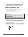
Connecting the transducer input.
• Separate physically throughout the whole trajectory, the signal lines
(Pt-100, mA, mV), from the power lines or command relays,
contacts, servomotors, actuators, etc.
• Use different and independent channels and conductors.
• For large signal line lengths, use cables with twisted and shielded
wires.
IMPORTANT NOTE:
The screen should be connected to the ground at a single point
pertaining to the reception area of the signal, in other words, a ground
terminal near the instrument.
DO NOT CONNECT TO GROUND THE 2 END POINTS OF THE
SHIELD.
• For Pt-100 inputs: Use 3-wire copper cable to compensate for the
errors caused by the parasite resistances of the connection cables of
the probe (use a section of 1.5 mm2 minimum).
• For mV inputs: Use copper cable of 1.5 mm2 in section as a
minimum. Respect the polarity.
• For mA inputs: Use copper cable of 1.5 mm2 in section as minimum.
Respect the polarity and add in parallel with the input terminals a Shunt
resistance of 2.5 Ohms (that are included with the module).
Installation / 27
DAS-8000 ver. 2.5
Connection to Ground.
• The DAS-8000 modules do not have ground connections due to the
total absence of metallic parts in their housing. Nevertheless, it is
advisable to place near the module some general ground terminal to
connect the shield screens of the connection or signal communication
cables.
• In any installation, the ground terminals of the modules should be
joined in the shape of a star on one point of the installation (metallic
mass), with a conductor from the same section as the electrical power
wires.
Digital serial communication.
The connection of the communications must be done with twisted
and shielded cable. The shield should also be connected to ground.
Installation / 28
DAS-8000 ver. 2.5
General precautions
• Before connecting to the electrical power grid, or inputs and outputs,
examine carefully the connection data label.
Installation / 29
DAS-8000 ver. 2.5
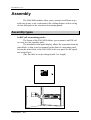
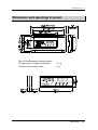
Assembly
The DAS-8000 modules allow you to mount it in different ways,
achieving in any event a reduction in the cabling distance with a saving
of time and space in the execution of mounting panels.
Assembly types
In DIN rail on mounting panels:
The format of the DAS-8000 allows you to mount it on DIN rail
or screw it to the assembly plate.
The detachable front panel display, allows the separation from the
main block, so that it can be mounted on the door of a mounting panel,
leaving the main block of the DAS-8000 in the rear panel for the signal
and control lines.
(The flat cable it can be enlarged until 2 m. length).
Installation / 30
DAS-8000 ver. 2.5
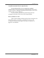
Assembly in standard electric connection box.
Its special design allows it to be mounted in a standard
connection box of the type used to house magnetothermic devices and
switches, salient or embedded, adjusting in measurements to the cut-off
window of the covers of said boxes.
For this assembly, dismount the terminal front panel and
exchange the direction of the circuit of the internal display.
Direct assembly on a wall.
Under certain working conditions and in clean environments, the
DAS-8000 module can be held (or embedded) directly in a wall,
avoiding the annoying control panels, necessary, nevertheless, in
aggressive environments.
Installation / 31
DAS-8000 ver. 2.5
DETACHABLE TERMINAL DISPLAY
It is an indistinct and separable unit, embedded in the protecting
front panel of the DAS-8000.
It is used to display the readings of the measured variables and
the logical data collected by one or several modules, or to modify the
general configuration of the DAS-8000 user parameters.
Its design allows it to be separated from the main block to use as:
• Interchangeable unit for local configuration of modules without
display DAS-8000/ND.
• Presentation of the measured variables in an accessible zone other
than the location of the DAS-8000.
EXTRACTION OF THE FRONT PANEL DISPLAY
The terminal display can be separated from the main block by
removing it from its lodging in the front panel of the DAS-8000 module.
For this reason, the terminal has a flat cable with connectors at
both ends, that allow you to disconnect it from the main printed circuit
and to reconnect once it is located in another panel.
To remove it from the front panel of the DAS-8000, proceed as follows:
1) Remove the front panel protection of the DAS-8000 freeing the
accessible anchorages from the outside.
2) With the protection of the DAS-8000 in your hands, observe in the
interior the 4 anchorages, two on each side of the terminal display,
that hold it in the opening of the front panel.
3) Proceed to press with a wide screwdriver, in order to free the
terminal and remove it through the front.
4) After removing the terminal display, put the protection back on the
DAS-8000, and plug the flat cable into its connector.
5) Close the opening with the front panel cover that is supplied with
the DAS-8000, ensuring that the flat cable comes out through the
opening provided at the end of the cover.
Installation / 32
DAS-8000 ver. 2.5
INVERTING THE DETACHABLE TERMINAL DISPLAY
The detachable terminal display is designed to have two front
panel measurements (48 x 144 mm and 45 x 144 mm) based on the type
of opening it is intended for.
Standard, it is supplied with the 48 x 144 mm size designed to be
embedded in front of a panel with an opening of 45 mm high x 144 mm
wide.
Nevertheless, the appearance of the display can be inverted to
have front panel dimensions of 45 mm x 144 mm, enabling you to adapt
it perfectly to the opening of a standard connection box of the type used
for magnetothermic, switches, etc.
To invert the position of the display, you should proceed as follows:
1) Remove the terminal display by removing it from the front panel
protection of the DAS-8000, as explained above.
2) Disconnect the flat cable from both sides: from its base, in both the
main printed circuit and in the circuit display.
3) With the terminal display in your hands, observe that the back part is
protected by an adhesive coat of polyester. Pull it off with care, and
you will have access to the holding screws of the two parts of the
terminal and the circuit display.
4) Unscrew them with a 5 mm screwdriver to separate the parts of the
terminal and remove the circuit display.
5) Once you have removed the circuit display, put it in place inverting
the position, ensuring that the connector of the flat cable remains
lined up with its opening and screwing it in again.
6) Replace with care the adhesive templates of the terminal, and
relocate the terminal display, this time, within the front panel
protection of the DAS-8000. Connect the flat cable to both
connectors.
7) Mount the front panel protection on the DAS-8000 again, this time
with the terminal coming from the inside, thus allowing the module
to fit in standard boxes, with a 45 mm opening.
Installation / 33
DAS-8000 ver. 2.5
ATTACHING AND DETACHING SYMMETRICAL DIN RAIL
DIN rail Assembly: DIN 46277/3 (IN 50022) Standard
Observe the DIN rail anchorage system of the DAS-8000. You
can see that a retractable bolt exists, that is accessible from the outside,
visible from the front on the lower part of the DAS-8000 module.
ATTACHING
First, place the DAS-8000 module hanging from the DIN rail by
the upper clamps of the back guide. Next, squeeze from the front so that
the bolt blocks the lower part of the DAS-8000 preventing it from
freeing itself. If, due to tolerances of the DIN rail, the bolt does not slide,
help the attachment by keeping the bolt down with the help of a flat
screwdriver. Once in place, free the bolt so that it will be anchored.
DETACHING
Through the lower part of the front panel, insert a screwdriver
into the blockading bolt, pressing downward. Next, pull the DAS-8000
gently, and lift it to free it from the rail.
NOTE:
Disconnect the terminal connector cables before performing this
operation.
Installation / 34
DAS-8000 ver. 2.5
Dimension and openings in panel.
Box of nonflammable thermal plastic.
Weight of the complete instrument:
Weight of the display alone:
710 g.
76 g.
Installation / 35
DAS-8000 ver. 2.5
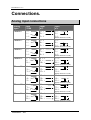
Connections.
Analog input connections
Analog
input
Channel 1
Input
Pt-100
1= +
2= 3= ⊥
Input
mV.
1= +
2= 3= ⊥
Channel 2
3= ⊥
4= 5= +
3= ⊥
4= 5= +
Channel 3
6= +
7= 8= ⊥
6= +
7= 8= ⊥
Channel 4
8= ⊥
9= 10= +
8 =⊥
9 =10= +
Channel 5
11= +
12= 13= ⊥
11= +
12= 13= ⊥
Channel 6
13= ⊥
14= 15= +
13= ⊥
14= 15= +
Channel 7
16= +
17= 18= ⊥
16= +
17= 18= ⊥
Channel 8
18= ⊥
19= 20= +
18= ⊥
19= 20= +
Input
mA.
1= +
2= 3= ⊥
(SHUNT resistance of 2,5 W)
3= ⊥
4= 5= +
(SHUNT resistance of 2,5 W)
6= +
7= 8= ⊥
(SHUNT resistance of 2,5 W)
8 =⊥
9 =10= +
(SHUNT resistance of 2,5 W)
11= +
12= 13= ⊥
(SHUNT resistance of 2,5 W)
13= ⊥
14= 15= +
(SHUNT resistance of 2,5 W)
16= +
17= 18= ⊥
(SHUNT resistance of 2,5 W)
18= ⊥
19= 20= +
(SHUNT resistance of 2,5 W)
Installation / 36
DAS-8000 ver. 2.5
Analog Inputs mA. Using the same power supply
In the case of mA. Signals coming from 2-wire transmitters
powered with the same 24 Vdc power supply and are connected to the
analog inputs of DAS-8000 module, the Shunt resistances should be
connected between positive (+) and ground (⊥
⊥ ) terminals, instead of
positive (+) and negative (-) terminals.
Example using independent power supply
Connection of two 4-20 mA. Signals coming from 2-wire
transmitters to two analog inputs of the DAS-8000 module, powered
with independent power supply.
24 Vdc
24 Vdc
Example using same power supply
Connection of two 4-20 mA. Signals coming from 2-wire
transmitters to two analog inputs of the DAS-8000, powered with the
same power supply.
24 Vdc
Installation / 37
DAS-8000 ver. 2.5
Digital input connections
The digital inputs allow you to detect HI logical signals between
12 and 48 volts, either in AC or DC.
Digital Input
Digital input 1
Digital input 2
Digital input 3
Digital input 4
Digital input 5
Digital input 6
Digital input 7
Digital input 8
NOTE:
Terminals
49 50
51 52
53 54
55 56
57 58
59 60
61 62
63 64
The digital Inputs don’t have polarity.
The electrical scheme of the digital inputs is as follows:
+Vdc
Digital Input
µP
NOTE:
Installation / 38
The input impedance is approximately 12 KΩ.
DAS-8000 ver. 2.5
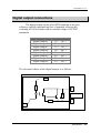
Digital output connections
The digital output consist of an NPN transistor in an open
collector, optically insulated and free of potential, allowing the
switching of 100 mA loads with an external voltage of 48 VDC
maximum.
Digital Output
Digital Output 1
Digital Output 2
Digital Output 3
Digital Output 4
Digital Output 5
Digital Output 6
Digital Output 7
Digital Output 8
Terminals
33= - 34= +
35= - 36= +
37= - 38= +
39= - 40= +
41= - 42= +
43= - 44= +
45= - 46= +
47= - 48= +
The electrical scheme of the digital outputs is as follows:
+Vdc
+
Digital Output
µP
Installation / 39
DAS-8000 ver. 2.5
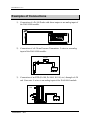
Examples of Connections
1) Connection of a Pt-100 Probe with direct output to an analog input of
the DAS-8000 module.
2) Connection of a 4-20 ma Pressure Transmitter. 2 wires to an analog
input of the DAS-8000 module.
24 Vdc
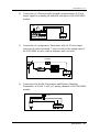
3) Connection of an RTD (Pt-100, Pt-1000, Ni 100, etc.) through a 4-20
mA Converter. 4 wires to an analog input of the DAS-8000 module.
Vac
Installation / 40
DAS-8000 ver. 2.5
4) Connection of a Thermocouple through a retransmission 4-20 mA.
output signal to an analog an Indicator with input of the DAS-8000
module.
Vac
5) Connection of a temperature Transmitter with a 4-20 mA output
converter in connection head. 2 wires (serial) to the analog input of
the DAS-8000 in series with an indicator and a recorder.
24 Vdc
6) Connection of a double Temperature and Relative Humidity
Transmitter, 4-20 mA 2 wire, to 2 analog channels of the DAS-8000
module.
24 Vdc
Installation / 41
DAS-8000 ver. 2.5
7) Actuation of a heating resistance from a Digital Output of the
DAS-8000, through a 24 V relay or contact with external power
supply.
24 Vdc
8) Activation of a Digital Input of the DAS-8000 from a proximity
sensor 2 wires (Namur, etc.) with an external power supply.
24 Vdc
9) Activation of a Digital Input of the DAS-8000 through the signal of
a push-button contact, with exterior power voltage from 12 to 48
Vac or Vdc.
24 V.
Installation / 42
DAS-8000 ver. 2.5
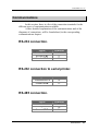
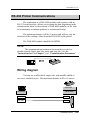
Communications
In this section, there is a list of the connection terminals for the
different types of communications available.
A more detailed explanation of the communications and of the
diagrams of connections, will be found ahead, in the corresponding
communications chapter.
RS-232 connection.
Signal
Transmission Tx
Reception Rx
Ground GND
Terminals
21
22
23
RS-232 connection to serial printer.
Signal
Transmission Tx
Ground GND
Terminals
24
23
RS-485 connection.
Signal
+
Ground GND
Terminals
27
28
26
Installation / 43
DAS-8000 ver. 2.5
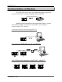
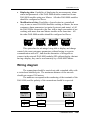
Communications architecture
The DAS-8000 can be used as an independent data acquisition
system connected to a printer, dumping data periodically:
Another typical connection is the connection of one or several
DAS-8000 modules connected to a central PC, supervising the
measurements of the process:
Connection of the DAS-8000 using RS-232:
Connection of a DAS-8000 network using RS-485:
DAS-8000 network connection, using RS-485, without PC:
Installation / 44
DAS-8000 ver. 2.5
Applications
The following are some of the applications for DAS-8000:
Measurement and data acquisition:
Research, Tests, Freezing chambers, Drying rooms, Butcher
rooms, Pharmaceutical industry, Thermal processes, Industrial Processes
in general, etc.
Supervising measurements:
Silos of grain or spoilable products, Level and tanks management,
Fermentation process in tanks, Hotels, Intelligent buildings, etc.
Control:
Intelligent buildings, Air conditioning, Ceramic tunnel ovens,
Painting, food industry, etc.
Management:
Productivity management, Time Counting, Presence control (by
means of software on a PC).
Installation / 45
DAS-8000 ver. 2.5
Installation / 46
DAS-8000 ver. 2.5
Description
Description / 47
DAS-8000 ver. 2.5
Description / 48
DAS-8000 ver. 2.5
Front panel description
The DAS-8000 has, in its complete version, a multifunction,
detachable terminal, for data monitoring and parameter configuration.
The display and keyboard are described in the following paragraphs.
Display
The data display is composed of 2 indicators of different sizes of 4
digits each, and also two 8 + 8 LED blocks:
• 1) The main indicator (upper) consists of 4 green digits, 14 mm.
high. It indicates the process value, the messages, and the
configuration variables.
• 2) The secondary indicator (lower), has 4 red digits, 7 mm. high.
It indicates the channel number that is being displayed, the module
number, and configuration messages.
• 3) 8 LED, for the indication of activation or deactivation of the
Digital Inputs (Lit = ON).
• 4) 8 LED, for the indication of activation or deactivation of the
Alarms (Lit =ON).
Description / 49
DAS-8000 ver. 2.5
Keyboard
The keyboard of the removable terminal of the DAS-8000,
consists of 4 keys situated under the LED, with the following functions:
• 5) FUNCTION / ESCAPE KEY.
It has two functions:
- allows access to read the different channels, parameters, etc. of the
display and configuration menus.
- allows you to exit in any branch of the menu tree.
• 6) INCREMENT KEY.
It has two functions:
- Increments the value of the digit that is blinking (editing of the
value), or selects menu positions.
- Allows manual printing.
• 7) SHIFT KEY.
It has two functions:
- Allows you to select the digit to be edited, moving it to the left,
enabling you to modify the value of a parameter with the Increment key.
- Activates/Deactivates the automatic scanning mode of analog inputs.
• 8) VALIDATION KEY (ENTER).
It has two functions:
- Saves the value that has been modified with the Increment and
Shift key.
- Allows you to introduce the module number to be displayed.
Description / 50
DAS-8000 ver. 2.5
Connection terminals
The DAS-8000 module has 2 rows of disconnectable terminals for
wires of 2 mm. diameter.
In the upper row, there are analog inputs connections consisting
of 8 blocks of two terminals (+ and -) for mV or mA with shunt, sharing
a third terminal, centered between every two channels, for line
compensation in Pt-100 inputs.
It also has three terminal blocks for communications and a
separate block for connection to the main power grid.
In the lower row, there are the digital input and output
connections composed of two blocks of 8 channels with two terminals
each one.
Description / 51
DAS-8000 ver. 2.5
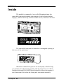
Inside
The module is composed of two well-differentiated parts: the
removable front panel terminal (that consists of the keyboard and the
display), and the main body with the module circuit, attached to the base.
The removable front panel is housed in a rectangular opening in
the cover of the main body.
When the terminal front panel is not used jointly with the body,
you need to close the housing opening with its protection cover that is
included with each DAS-8000, that nevertheless, allows the passage of
the Connection Cable when the front panel is mounted externally.
Description / 52
DAS-8000 ver. 2.5
The electrical connection of these two parts (display and keyboard
to the main circuit), is carried out with a flat 20-wire cable, integrated
into the interior in a prefolded way.
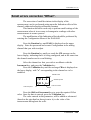
How to open it
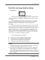
To open the instrument, you
need to press any of the four clips
placed at both sides of the base, that
secure the upper cover of the module.
To push the clip towards the
inside and free the cover, you can use
a screwdriver, or even the fingers,
removing the cover with the other
hand.
Description / 53
DAS-8000 ver. 2.5
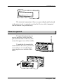
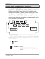
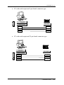
Analog input configuration “Jumpers”.
The DAS-8000 module allows you to configure from the keyboard
RTD (Pt-100) or LINEAR (10-50 mV, 4-20 mA, 0-20 mA or Nonlinearized thermocouples) signals, because they are shipped already
calibrated. The adaptation of the input terminals for each type of signal
depends on the positions of the internal jumpers of each channel.
When opening a DAS-8000 module and removing the cover, you
will notice on the printed circuit board, on the side of the components,
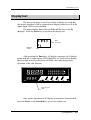
the layout of the jumpers for configuration of the analog channels, just as
you see them in the following picture:
“jumpers
Ch 1
“jumpers”
Ch 3
“jumpers”
Ch 2
“jumpers”
Ch 5
“jumpers”
Ch 4
“jumpers”
Ch 7
“jumpers”
Ch 6
“jumpers”
Ch 8
POWER
SUPPLY
Port Selection
RS-232 / RS-485
Each of the 8 channels has one disconnectable, black jumper, that
should be connected according to the type of sensor used, as indicated in
the following figure:
Pt-100 INPUT.
LINEAR INPUT. 10-50 mV.
4-20 mA, 0-20 mA, Non-linearized thermocouples.
(With SHUNT resistance of 2’5 W in parallel with input
terminals).
Description / 54
DAS-8000 ver. 2.5
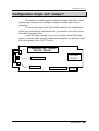
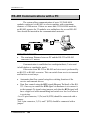
Configuration straps and “Jumper”
The straps are small printed circuit board areas that allow you to
join its edges by means of welding, in order to modify aspects of its
operation.
To locate the Strap of the DAS-8000 related to the modification
of the type and speed of communications, you need to access the circuit
from the components side.
Locate the strap visually, just as you see them in the following
picture (visually make sure the printed circuit number on the lower right
side corresponds to the C/477-4 code):
4020M
J1: Selection Port “Jumper”
RS-232 / RS-485
POWER
SUPPLY
S1: Baud Rate
S2: Don´t Use
Circuit Number
C/474-4
Description / 55
DAS-8000 ver. 2.5
Configuration of communication type
J1 Jumper: Setting pin layout for RS-232 or RS-485 output terminals.
The position of this “Jumper” allows you to select the RS-232 or
RS-485 standard of communication, between the DAS-8000 module and
the PC, determining at the same time the output terminals:
21, 22, and 23 for RS-232, or 26, 27, and 28 for RS-485.
RS-485
RS-232
Communication speed setup
S1 Strap: Communications speed: Set to 9600 baud, or selectable from
the configuration menu.
The joining of the S1 Strap will set the communications output.
already in RS-232 or RS-485, to a speed of 9600 baud. Normally, this
strap is open, thus allowing you to modify the communications speed by
means of the configuration menu, selecting 9600, 19200 or 38400 baud.
Software Configuration
9600 Bauds fixed
S2 Strap: DO NOT USE.
The strap are reserved for future implementations and factory
settings. They should not be modified.
Description / 56
DAS-8000 ver. 2.5
Instructions for use
Instructions for use / 57
DAS-8000 ver. 2.5
Instructions for use / 58
DAS-8000 ver. 2.5
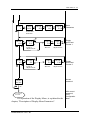
Menu tree
The operation of the DAS-8000 in its operational level, both in
standard use, as well as in configuration, is based on 2 menus that allow
you to have access to the totality of DAS-8000 functions:
• Display menu: It is the main operation menu, and the one that will
be most frequently used. With it, you can access the viewing of the
analog measurements and alarm parameter modification of the
module being used, or of any another connected to the same
communication network.
• Configuration menu: This menu allows you to access the
parametrization and configuration of all the DAS-8000's available
options. Access to the Configuration Menu is protected by means of
the access password.
The following is a description of the two menus.
Display menu
The Display Menu appears when you start the module, allowing
you to display the 8 measurements received by the analog channels,
change the parameters most frequently changed in the configuration of
alarms, setpoint, hysteresis, and status, (Password Alarm is required to
enabled the access to alarm menu) and display the 2 counters.
The last level of the menu (PASS) requests the access Password to
enter the configuration menu.
The diagram of operation of the Display Menu is shown in the
following figure:
Instructions for use / 59
DAS-8000 ver. 2.5
DISPLAY MENU
Start
XXXX
1
MO
Display
Channel 1
xx
x
XXXX
2
Change of
Module to
Display
Display
Channel 2
XXXX
3
Display
Channel 3
XXXX
4
Display
Channel 4
XXXX
5
XXXX
6
XXXX
7
XXXX
8
Instructions for Use / 60
Display
Channel 5
Display
Channel 6
Display
Channel 7
Display
Channel 8
DAS-8000 ver. 2.5
ALAr
1
XXXX
U1
PASL
0000
XXXX
SP
PassWord
Access Alarm
Parameters
Set-Point
XXXX
S1
Display
Counter 1
“Significant Part”
XXXX
U2
XXXX
S2
Display
Counter 2
“Significant Part”
XXXX
HY
X
Alarm
Parameters
XXXX
St
X
Hysteresis
X
Status
XXXX
PS
XXXX
PU
X
Preset
“Unit Part”
XXXX
PU
Preset
“Unit Part”
X
Display
and Preset
Counter 1
Preset
“Significant Part”
XXXX
PS
Preset
X “Significant
X
Part”
Display
and Preset
Counter 2
Access
password
PASS
XXXX
0
To Configuration Menu
The operation of the Display Menu, is explained in the
chapter, "Description of Display Menu Parameters”.
Instructions for Use / 61
With correct
password,
Go to
Configuration
Menu
DAS-8000 ver. 2.5
Configuration Menu
The Configuration Menu displays upon introducing in PASS the
correct access password. Through it you can modify all the parameters of
the instrument (type of input, ranges, type of alarms, communications,
counters and change of the access password), and to proceed to a
recalibration of the analog inputs.
NOTES:
• The DAS-8000 is supplied without any PassWord (0000).
• To introduce a PassWord, refer to section “Change of General
PassWord” in the “Configuration” chapter.
VERY IMPORTANT:
Access to the Configuration Menu is for exclusive use of the
instrumentation technicians and managers process, because it enables
you to modify important parameters, possibly including the decalibration
of the analog inputs if a person without sufficient knowledge enters the
calibration section.
If you access the calibration menu without first connecting a
signal generator to the inputs, do NOT press the Validation key. Exit
with the Function key.
The final positions of the configuration menu allow:
•
•
•
To Modify the General PASSWORD, PASS Menu.
To Modify alarm configuration Password, PASL Menu.
Introducing PassWord PASS enables to acced to configuration menu
again.
The operation of the Configuration Menu is explained in the
"Description of Configuration Menu Parameters" section.
The operation diagram of the Configuration Menu displays in the
following figure:
Instructions for Use / 62
DAS-8000 ver. 2.5
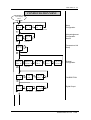
CONFIGURATION MENU
From Display
Menu
ConF
AL x
ABCD
AL x
Alarm Parameters
ConF
AC
Alarm
Configuration
ABCD
AL x
Delay of alarm Connection
Acknowledgement
Configuration
Alarms
00CD
AC
Acknowledgement
Parameters
Temperature Unit
Setup
ConF
CF x
ConF
CH x
ABCD
CHx t
Channel
Parameters
ConF
CL x
ConF
do x
x x x x
CHx_
Lo-Range
x x x x
AJ x_
x x x x
AJ x−
Adjust. Minimum
Adjust. Maximum
x x
do x t
Type of Output
Local / Remote
ABCD
do xC
x x x x
CH x−
Hi-Range
x x x x
CH xo
Channel
Configuration
Indication Offset
CALIBRATION
Digital Output
Digital Output
Parameters
Instructions for Use / 63
DAS-8000 ver. 2.5
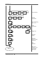
ConF
Co
00 x x
CoAd
Communications
Address
ConF
Cn 1
ConF
Cn 2
Counter 2
Configuration
Communications
000A
CoSd
TEST
Co xx
Speed
Communications
Test
ABCD
CnxC
Counters
Configuration
Counter
Parameters
ConF
Mo x
ConF
Pr
Type of Monitoring
(Master / Slave)
x x xx
Pr Cy
00 x x
Pr Fr
00 x x
Pr LA
ABCD
Pr C
Cycle Time
First Module
To Print
Last Module
To Print
Printer
Configuration
TEST
dy
00CD
Pr A
Printer
Configuration
Display Test
Alarms Printer
Configuration
x x x x
PASS
PassWord
Change
x x x x
PASS
PassWord
Change of Alarm
Parameters
PASS
x x x x
Back to
Display Menu
Instructions for use / 64
Input
PassWord
With correct
PassWord, go to
Configuration
Menu again
DAS-8000 ver. 2.5
Description of Display Menu
parameters
The following is a description of the process for the display of
measurements and data, of the module being used as well as others, in
the case that several are linked in a network, from one terminal display.
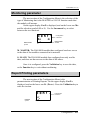
Displaying the Software version
As soon as the DAS-8000 module is started, three messages
appear on the display, the first one does a test of display unit switching
on all segments.
The second message identifies the self-test performed by the
device when it is started:
self
t e s t
After approximately one second, the display shows the software
version that is operational in the DAS-8000 module:
v02.5
t e s t
This indication remains on the display for a few seconds, then the
next message shown is the one displayed for the first analog channel
and, thus, the DAS-8000 is already operational.
23.1
1
Instructions for use / 65
DAS-8000 ver. 2.5
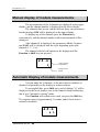
Manual display of module measurements.
The measurements of the 8 channels are displayed on the upper
display, and the channel number is displayed on the lower display.
The channels that are not enabled will not show a measurement,
but the message OFF will be displayed on the upper display.
To display any of the channels press the Function key
consecutively, and the channel number with its measurement will be
displayed.
After channel 8 is displayed, the parameters ALAr, Counters,
and PASS, will be displayed with the cycle beginning again with
channels 1, 2, 3, etc.
The channel selected will remain on the display until the
Function or Shift keys are pressed.
23.1
Analog channel
measurement
1
Analog channel
number
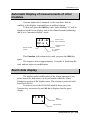
Automatic Display of module measurements.
You can make the 8 channels, or the ones that are enabled, be
displayed sequentially on the display in endless rotation.
To accomplish this, press Shift once, and a blinking "A" will be
displayed on the lower display, next to the channel number indicating
that it is in "automatic viewing" mode.
This Function will remain active until you press the Shift key.
The sequence time is approximately 2 seconds, and is fixed, since it
cannot be modified.
23.1
a 1
Instructions for use / 66
DAS-8000 ver. 2.5
Manual Display of the measurements of other
modules.
This Function allows you to read from a central module that has
a terminal display, and in addition, any another module connected to its
network is configured as Master. As in the previous case, the display
function can be Manual or Automatic.
To display any channel of another module in the network, press
the Validation key once, starting with the normal status displaying any
channel (having no effect from the messages: Alar and Pass).
On the upper display, the message Mo will be displayed, and on
the lower one the module number read the last time (if there is only one
DAS-8000, its number is displayed).
Modify with the Shift and Increment keys, and enter the module
number you wish (different from the one that you use for display). Press
the Validation key.
mo
02
NOTE:
If the module is configured as Slave, the Validation key has no
effect. It is indispensable that the DAS-8000 be configured as a Master.
If the module number selected is incorrect, this indicates that it is
not in the communications line, has a different communications speed,
or is configured as RS-232 output, will be displayed briefly on the
display the message ErrC, indicating that a communication error exits.
If the communication is correct, the reading of the remote module
will be shown on the display and on the Leds the status of its digital
channels.
On the lower display, 2 digits will be displayed to the left with the
module number that is being displayed.
Then you can read the channels of that module:
Instructions for use / 67
DAS-8000 ver. 2.5
175.1
02
Remote module
number
Channel 1 from Module
2 measurement
1
Remote channel
number
Press the Function key consecutively, and the channel number
and the value of its measurement will be displayed. After channel 8, the
ALAr and PASS parameters appear, beginning again with channel 1.
The channel selected will remain on the display as long as you do
not press the Function or Shift keys.
NOTE:
When the channels of another module are read from a local
module, upon reaching PASS, only entering the access password will
allow you to enter the configuration of your own module, and it is
impossible to gain access to the configuration of the remote module.
Instructions for use / 68
DAS-8000 ver. 2.5
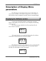
Automatic Display of measurements of other
modules.
You can display the 8 channels, or the ones those that are
enabled, in the display sequentially in an endless rotation.
To this end, press the Shift key once, and a blinking "A" will be
displayed on the lower display, next to the channel number indicating
that it is in "automatic display" mode.
-23.1
02 a 1
Channel 1 from
mod. 2 measures
Remote channel
number
Remote module
number
“A” : Indicates
sequence
This Function will remain active until you press the Shift key
again.
The sequence time is approximately 2 seconds, is fixed from the
start, and not subject to modification.
Alarm data display.
The display and/or modification of the Alarm parameters (setpoint, hysteresis, and status) can be performed within the Alarm
Parameters section of the display menu. This section is protected with
PassWord (PASL).
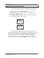
In order to access the DAS-8000 module alarm, press the
Function key consecutively until ALAr is displayed on the upper
display.
alaR
1
Alarm
mnemonic
Alarm Number
Instructions for use / 69
DAS-8000 ver. 2.5
The number of the last alarm will be displayed blinking. Select
with the Increment key the alarm number that you wish to display
and/or modify.
If the alarm password is enabled, in the upper display will appear
PASL, and in the lower one 0000 with the right side digit blinking.
Introduce using Increment and Displacement keys the password and
press the Validation key, and you will enter the Alarm Configuration
section.
pasl
0 0 0 0
Alarm PassWord
mnemonic
PassWord value
If the password introduced is not correct, the access to the alarm
sub-menu is denied. If it has been introduced correctly then will appear
the sub-menu to display and/or modify alarm parameters, explained in
the following sections.
NOTES:
• If through configuration, the alarm is disabled, the access to these
parameters is denied.
• The unit is supplied without any Password (0000).
• To introduce a password, refer to section “Change of password of
alarm parameters”.
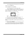
Manual alarm acknowledgment.
For certain industries, this is a unique and useful function,
featuring a characteristic behavior, which has been implemented in the
alarm functions already featured on the DAS-8000 module.
Instructions for use / 70
DAS-8000 ver. 2.5
Its main characteristics are:
• Acknowledgement alarms have special features.
• All alarms are recognized by the same actuator (digital input or
manually from the keyboard).
• All alarms acts on the same digital output (“horn” output).
• Acknowledgement is timed, such that the acknowledgement digital
output will act again after a preset time (in the DAS-8000 module a
fixed time of 15 minutes has been preset), if the alarm condition has
not yet disappeared.
• If, another acknowledgement alarm trips while an alarm
acknowledgement is being timed, the “horn” digital output is again
tripped and the alarm must be acknowledged again.
The DAS-8000 module allows any normal alarm to be set up, as
an acknowledgement alarm (please see the section on alarm and
acknowledgement alarm setup). In this setup, you can enable or disable
this function and set the acknowledgement digital inputs and output
(also called “horn” output).
The alarm acknowledgement function can be implemented
through the digital inputs mentioned above or manually through the
DAS-800 keyboard.
To perform the alarm acknowledgement function manually, press
the Shift key while it appears on the alarm option display.
alar
1
Pressing this key (or an acknowledgement by a digital input
occurs) will cause the previously tripped acknowledgement output to
return to its stand-by condition and start timing (15 minutes). If the
alarm trip condition has not disappeared after this time period has
elapsed, the acknowledgement output will trip again.
Instructions for use / 71
DAS-8000 ver. 2.5
How to see and/or modify the setpoint of an
alarm.
In the lower display, the SP (set-point) symbol is displayed, and
on the upper display the value of the set-point that it has assigned. If
you only wish to see the value, press the Function or Validation key,
and nothing is modified. If you wish to change the value of the setpoint, use the Increment and Shift keys to enter the new data. Once
completed, press the Validation key to save the new value.
0375
sp
NOTE:
SETPOINT is the value in physical units where the alarm
changes its status.
How to see and/or modify the hysteresis of
an alarm
After pressing Validation, the HY (Hysteresis) symbol will be
displayed on the lower display, and on the upper the preset current value.
If you wish to see the value only, press the Function or Validation key
to exit, without modifying the data. If you wish to change the value, use
the Increment and Shift keys to enter the new data. Then, press the
Validation key to store the new value.
0050
hy
Instructions for use / 72
DAS-8000 ver. 2.5
NOTE:
Hysteresis of commutation is the margin in engineering units
between the activation and deactivation of an Alarm. It allows you to
separate the alarm status 1 and 0, in order to avoid continuous changes
in the commutation of the Digital Output.
How to see and/or modify the status of alarm
After pressing Validation, St (Status) symbol will be displayed on
the lower display, and on the upper display, the current status ON or
OFF (enabled or not) of the alarm selected. If you only wish to see the
status, you can exit by pressing the Function or Validation key, without
modifying the data. If you wish to modify the enabling of the Alarm, use
the Increment key to select ON or OFF. Then, press the Validation key
to store the new status.
OFF
1
St
Instructions for use / 73
DAS-8000 ver. 2.5
Counter operation criteria
The criteria used for designing DAS-8000 module internal
counters are given below.
In each DAS-8000 module two counters have been implemented,
each provided with three digital inputs: counting input, reset input, and
disable input, as shown in the figure below.
RESET Digital Input
RES
COUNTER Digital Input
CLK
CNT
PRS
DO
COUNTER Display
PRESET
PRESET Output
INH
DISABLE Digital Input
The various counter blocks inputs and outputs are as follows:
• Counting Digital Input: Used to enter the pulses to be counted. The
counter will count up each time a pulse rise edge is available and the
maximum frequency does not exceed 40 Hz with pulse on-time
values of at least 15 ms.
• Reset Digital Input: Resetting the counter can be performed by
activating a digital input or by manually pressing a key on the
DAS-8000 keyboard.
• Disable Digital Input: The counter can be stopped at any moment,
when so requested by the disable digital input. This input has priority
over the counting input, i.e. while the disable input is on, the counter
will hold its last accumulated value.
Instructions for use / 74
DAS-8000 ver. 2.5
• Preset: Freely-configurable numeric value that allows a value to be
assigned to each counter, and activates the digital output when
exceeded by the counter.
• Preset digital output: Freely configurable digital output indicated
above.
Some of these digital input/outputs are fixed and others are
configurable for the two counters. The relationship is as follows:
DIGITAL INPUT No.
COUNTER DISABLE RESET
COUNTER 1
1
2
3
COUNTER 2
4
5
6
DIGITAL OUTPUT No.
0= Without Output
1/8= Output No.
0= Without Output
1/8= Output No.
Both the counter itself and its disable and reset input can be
enabled or disabled (please see item Counter setup).
NOTES:
• The default counter settings when a reset is performed or a counter is
set up is 0.
• Counters do not allow negative values.
• Counter display and/or counter preset setup are only possible if they
are enabled.
Instructions for use / 75
DAS-8000 ver. 2.5
Counter Display
Counter display is presented in two data groups, the first is called
“unit part” and consists of the first counter digit and the other group is
known as the “significant part”, consisting of the four most significant
digits. The maximum value indicated by the counter is, therefore,
99,999,999, i.e. 8 numeric digits.
Since the DAS-8000 has only a 4-digit display, counter display
will be performed by first showing the unit part and then displaying the
significant part sequentially when the Increment key is pressed.
Continuous pressing of the Increment key toggles between the “unit
part” and the “significant part”.
The image appearing on the display is as follows:
5643
Value of the “Unit Part” of the
counter number 1
u 1
Counter Number
1 or 2
“U” : “Unit Part” Symbol
Pressing the
INCREMENT key
0912
Value of the “Significant Part” of
the counter number 1
s 1
Counter Number
1 or 2
“S” : “Significant Part” Symbol
In this case, the counter number 1 value would be 09.125.643
Instructions for use / 76
DAS-8000 ver. 2.5
Displaying and/or changing the counter
preset value
From the counter display, whether you are displaying the unit part
or the significant part, pressing the Enter key allows the preset unit part
display to be accessed.
0125
pu
PRESET Value of the
“Unit Part” of the counter
“PU” : “PRESET” symbol of the “Unit Part”
If you only want to see the value, press the Validation or
Function keys, which does not cause any changes. To change the
PRESET value in the unit part, use the Increment and Shift keys to
enter the new data, then press the Enter key to accept the new values.
Press the Enter key to access the preset significant part display.
0000
ps
PRESET value of the
“Significant Part” of the counter
“PS” : “PRESET” symbol of the “Significant Part”
To edit the value or leave them as is, the same criterion will
apply.
NOTES:
• Only positive decimal system values are allowed for the unit or
significant part PRESET value.
• The minimum PRESET value will be 0 and the maximum one will be
99,999,999.
• The count can be displayed only if the counter is enabled (to enable
it, please see the section Counter Setup).
• The counter value can be displayed only if the counter preset digital
output is enabled (to enable it, please see the section Counter preset
setup).
Instructions for use / 77
DAS-8000 ver. 2.5
Performing a Counter Reset
Counter reset can be performed at any time in one of two ways:
• By activating the corresponding digital input
(digital input number 3 for counter number 1 and digital input
number 6 for counter number 2).
• By pressing the Shift key 3 times while in the counter display (both
in the significant part and in the unit part).
0123
u1
0005
s1
The first time the Shift is pressed causes the first digit of the
upper display to blink, the second time key is pressed causes the second
digit of the same display to blink, and the third time that this key is
pressed, the counter is reset, the display returns to its normal status
(blinking indicates that a reset is going to be performed). When a
counter reset is not desired, press the Shift key to prevent presetting.
Instructions for use / 78
DAS-8000 ver. 2.5
Printing measurements of
DAS-8000 modules
The DAS-8000 is able to send directly, to a serial printer (without
PC), the measurements read in its analog channels, both automatically
(with a preconfigured interval between print jobs) and manually
(optional). Also, when they are linked in a network, besides its own
channels, they can dump the channels of the other preconfigured
DAS-8000 Modules.
The listing generated by the printer uses a relative value of time
corresponding to the moment when the system of DAS-8000 modules
was created, printing in HHHH:MM:SS (hours : minutes : seconds)
format. When the time reaches its maximum, it begins again at
0000:00:00. This value is not saved in the event of electrical power
network failures.
Automatic mode
To dump the data in an automatic way, the DAS-8000 module
should have preset the printer parameters in the Configuration Menu
(cycle time, modules to print, and transmission format).
Sending printer data occurs from the moment the DAS-8000 is
configured, with the data being sent to the RS-232 channel even if the
printer is not connected.
Manual mode
To dump data to a printer manually, press the Increment key only
once, with the DAS-8000 module in a normal channel display mode.
The Manual dump is independent of the automatic one, so that if
you press the increment key during the interval between automatic printouts, a dumping of the existing data at that time will be produced as
well.
Instructions for use / 79
DAS-8000 ver. 2.5
Sample of data listing in printer with dump frequency of 60 seconds, and
with channel 8 inactive:
Relative time
at starting the
DAS-8000
Channels 1 to 7
listing measures
Module number
HHHH:MM:SS Mod. __C1__ __C2__ __C3__ __C4__ __C5__ __C6__ __C7__ __C8__
0000:01:30 1
120.5 23.6
-4.6
4.8
98.6 345
12.5
HHHH:MM:SS Mod. __C1__ __C2__ __C3__ __C4__ __C5__ __C6__ __C7__ __C8__
0000:02:30 1
118.5 23.5
-4.6
4.3
99.6 346
12.2
HHHH:MM:SS Mod. __C1__ __C2__ __C3__ __C4__ __C5__ __C6__ __C7__ __C8__
0000:03:30 1
124.3 23.4
-4.5
4.4
100.6 349
12.2
HHHH:MM:SS Mod. __C1__ __C2__ __C3__ __C4__ __C5__ __C6__ __C7__ __C8__
0000:04:30 1
122.3 23.1
-4.5
4.6
100.2 348
12.5
HHHH:MM:SS Mod. __C1__ __C2__ __C3__ __C4__ __C5__ __C6__ __C7__ __C8__
0000:05:30 1
122.2 23.3
-4.5
4.9
99.8 343
12.5
HHHH:MM:SS Mod. __C1__ __C2__ __C3__ __C4__ __C5__ __C6__ __C7__ __C8__
0000:06:30 1
121.5 23.0
-4.6
4.0
99.6 342
12.6
HHHH:MM:SS Mod. __C1__ __C2__ __C3__ __C4__ __C5__ __C6__ __C7__ __C8__
0000:07:30 1
120.5 23.1
-4.7
4.1
98.6 341
12.7
HHHH:MM:SS Mod. __C1__ __C2__ __C3__ __C4__ __C5__ __C6__ __C7__ __C8__
0000:08:30 1
124.6 23.0
-4.8
4.3
98.4 345
12.8
Dumping data to printer from other network
modules
A DAS-8000 MASTER module allows, besides sending its data to
a printer, the collection for printing purposes of the data from all the
other DAS-8000 modules connected to the network and in the order they
were enabled.
Besides, a system of DAS-8000 modules connected in a network,
allows you to generate reports on several printers at the same time, from
one or several of the modules, provided they were configured as
Instructions for use / 80
DAS-8000 ver. 2.5
MASTER, being a matter of indifference whether the rest are configured
as MASTERS or SLAVES.
Nevertheless, to avoid data collisions in the communications, you
will need to generate a data dump (with the Increment key) from a
single Master module at a time.
To dump data automatically, you must preestablish the printer
parameters for the DAS-8000 module in the Configuration Menu: cycle
time, transmission format, and also the number of the first and last
module to be printed.
This multiple method of printing, allows, as with a single module,
both the automatic as well as the manual dump by means of the
Increment key.
A sample of automatic listing with a listing frequency of 3600
seconds (1 hour), with 3 modules on the network (numbers 1, 2, and 3)
follows:
Relative time
at starting the
DAS-8000
Channels 1 to 8
listing measures
Module number
(1, 2 and 3)
HHHH:MM:SS Mod. __C1__ __C2__ __C3__ __C4__ __C5__ __C6__ __C7__ __C8__
0001:00:30 1
120.5 23.6
-4.6
4.8
98.6 345
12.5
-9.8
2
257.5
5.6
44.6
2.2
4.0 645
.5
45.6
3
24.5
-.6
-0.6 24.4
28.0
77
1.5
2.7
HHHH:MM:SS Mod. __C1__ __C2__ __C3__ __C4__ __C5__ __C6__ __C7__ __C8__
0002:00:30 1
120.4 23.6
-4.6
4.8
98.6 345
12.5
-9.8
2
257.5
5.6
44.6
2.2
4.0 645
.5
45.6
3
24.5
-.6
-0.6 24.4
28.0
77
1.5
2.7
HHHH:MM:SS Mod. __C1__ __C2__ __C3__ __C4__ __C5__ __C6__ __C7__ __C8__
0003:00:30 1
120.3 23.6
-4.6
4.8
98.6 345
12.5
-9.8
2
257.5
5.6
44.6
2.2
4.0 645
.5
45.6
3
24.5
-.6
-0.6 24.4
28.0
77
1.5
2.7
HHHH:MM:SS Mod. __C1__ __C2__ __C3__ __C4__ __C5__ __C6__ __C7__ __C8__
0004:00:30 1
120.1 23.6
-4.6
4.8
98.6 345
12.5
-9.8
2
257.5
5.6
44.6
2.2
4.0 645
.5
45.4
3
24.5
-.6
-0.6 24.4
28.0
77
1.5
2.7
HHHH:MM:SS Mod. __C1__ __C2__ __C3__ __C4__ __C5__ __C6__ __C7__ __C8__
0005:00:30 1
120.2 23.6
-4.6
4.8
98.6 345
12.5
-9.8
2
257.4
5.6
44.6
2.2
4.0 645
.5
45.6
3
24.0
-.6
-0.6 24.4
28.0
77
1.5
2.7
HHHH:MM:SS Mod. __C1__ __C2__ __C3__ __C4__ __C5__ __C6__ __C7__ __C8__
0006:00:30 1
120.5 23.6
-4.6
4.8
98.6 345
12.5
-9.8
2
257.5
5.6
44.6
2.2
4.0 645
.5
45.6
3
24.5
-.6
-0.6 24.4
28.0
77
1.5
2.7
Instructions for use / 81
DAS-8000 ver. 2.5
Printing DAS-8000 module alarms
The DAS-8000 allows the alarms generated to be sent directly to
a serial printer (without a PC computer), listing both the on and off data.
The alarm listing generated in the printer uses a relative time
value corresponding to the time the DAS-8000 module was started, with
this time printed in the format HHHH:MM:SS (hours:minutes:seconds).
When this time reaches its maximum, it starts from 0000:00:00 again.
This value is not stored when a power failure occurs.
It should be stressed that alarm dumping occurs only when the
DAS-8000 module is connected to a printer. It is not possible to dump
alarms for other DAS-8000 modules that may be connected through a
communications network.
Alarm Printing
To dump the alarms, the DAS-8000 module must have its printer
parameters preset in the setup menu (transmission format) as well as the
alarm printing parameter activated (please see “Alarm printing
parameters”).
Alarms are sent to the printer from the moment the DAS-8000 is
set up, with data sent to the RS 232 channel even if the printer is not
connected.
Instructions for use / 82
DAS-8000 ver. 2.5
Example of a printed alarm listing:
Alarm Number and
STATUS (ON /OFF)
Relative time at
starting the
DAS-8000
Set-Point Value of
the Alarm
Process Value
0000:01:30
0000:02:30
0000:03:45
0000:03:50
0000:11:30
0000:14:34
0000:25:35
0000:45:30
0000:51:36
0000:59:59
0001:00:30
0001:01:30
0001:02:33
0001:12:30
0007:45:40
0017:01:30
0017:11:50
0024:01:30
Alarm
Alarm
Alarm
Alarm
Alarm
Alarm
Alarm
Alarm
Alarm
Alarm
Alarm
Alarm
Alarm
Alarm
Alarm
Alarm
Alarm
Alarm
1:
1:
2:
2:
1:
1:
4:
4:
1:
5:
1:
1:
5:
3:
1:
3:
1:
1:
ON
OFF
ON
OFF
ON
OFF
ON
OFF
ON
ON
OFF
ON
OFF
ON
OFF
OFF
ON
OFF
SP=050.0
SP=050.0
SP=010.0
SP=010.0
SP=050.0
SP=050.0
SP=124.0
SP=124.0
SP=050.0
SP=076.0
SP=050.0
SP=050.0
SP=076.0
SP=021.0
SP=050.0
SP=021.0
SP=050.0
SP=050.0
PV=126.1
PV=045.5
PV=012.1
PV=008.2
PV=067.1
PV=049.2
PV=126.1
PV=123.1
PV=051.1
PV=077.5
PV=049.6
PV=067.1
PV=074.1
PV=022.2
PV=046.5
PV=019.3
PV=055.1
PV=045.1
Instructions for use / 83
DAS-8000 ver. 2.5
Instructions for use / 84
DAS-8000 ver. 2.5
Configuration
Configuration / 85
DAS-8000 ver. 2.5
Instructions for Use / 86
DAS-8000 ver. 2.5
Description of Configuration
Menu parameters
The Configuration Menu is protected by means of an access
password.
NOTES:
• The unit is supplied without PassWord (0000).
• To introduce a password, refer to section “Change of general
PassWord”, at the end of the “Configuration” chapter.
PassWord Input
To enter, press the Function key consecutively until the Password
symbol is displayed:
pass
0 0 0 0
Mnemonic
PassWord
PassWord value
“0000” will appear on the lower display with the right digit
blinking. Enter the access password with the Increment and Shift keys,
and press the Validation key.
If the password is not correct, you will not be able to access the
display menu. If it has been entered correctly, CONF will be displayed
on the upper display, and on the lower one the first section of the
Configuration Menu: "AL x" Alarms (with "x" as the alarm no.)
Configuration / 87
DAS-8000 ver. 2.5
Click the Function key consecutively to display, one after another,
the rest of the configuration sections:
“AC”
“CF x”
“CH x”
“CL x”
“Do x”
“Co”
“Cn x”
“Mo x”
“Pr”
“TEST dy”
“PASS”
“PASL”
Alarm acknowledgement parameters.
Temperature unit configuration
Channel Configuration.
Calibration.
Digital Output Configuration.
Communications Configuration.
Counter configuration.
Type of Monitoring.
Printer Configuration.
Display test
Modification of the Access Password.
Modification of the Alarm Password.
In the following sections, we provide a detailed explanation of all
the sections of the Configuration Menu listed above, except the
Calibration section, that has an independent chapter dedicated to it.
Alarm parameters
The first section of the Configuration Menu is the
pre-configuration of Alarms. On the upper display, ConF is displayed,
and on the lower one, AL together with the last Alarm number
configured. Use the Increment key to indicate the Alarm number that
you wish to configure, and press the Validation key.
conf
al
1
Configuration
mnemonic
Alarm number
Alarm symbol
Configuration / 88
DAS-8000 ver. 2.5
A 4-digit code is displayed on the upper display, with the current
configuration of the Alarm no:
Analog channel No.
assignment
Digital Output
assignment
Alarm type
selection
Digital Input
assignment
8113
al
1
Alarm No.
Alarm symbol
Use the Shift key to select the digit that you wish to modify. Each
digit of that code represents an Alarm configuration parameter, with the
value of the digit a number that represents one of several possibilities
that this parameter can assume.
Select each one of them based on the configuration you want and
what is explained in the following sub-sections:
Disabling the Alarm Output. Digital Input
Assignment.
Digital Input
assignment
8113
al
1
Alarm No.
This digit allows you to select the Digital Input no. that you wish
to use as alarm Disabling.
When, in situation of alarm, you send an activation signal to the
digital input selected, the digital output assigned will be deactivated, so
that, although a condition of alarm still exists, the digital output will
remain canceled.
Configuration / 89
DAS-8000 ver. 2.5
This function is used to cancel provisionally the luminous
displays, acoustic, etc. connected to the digital outputs acting as an alarm
activation, allowing the attendant to turn off the warning until the
situation that caused the alarm has been solved.
Another practical application is in freezing chambers, in which
the action of defrosting is not an alarm situation, but can lead to a rise in
temperature above the alarm value established.
The assignment values of possible Digital Input are:
0:
No Digital Input will be assigned.
1 to 8: Selection of the Digital Input number that you will assign as a
Disabling of the Alarm no. in the configuration.
NOTE:
The Digital Input number can not only be assigned to an alarm,
but can also be repeated in any alarm (using it then as a general
disabling of all the alarms).
Assignment of Digital Output.
Digital Output
assignment
81
113
al
1
Alarm number
This digit allows you to select the Digital output number that you
will use as the output of the alarm.
The possible assignment values of the Digital Output are:
0:
No Digital Output will be assigned.
1 to 8: Selection of the Digital Output no. that will be assigned to the
Alarm number being configured.
Configuration / 90
DAS-8000 ver. 2.5
NOTE:
The Digital Output No. can be assigned not only to one alarm, but
can also be repeated in any alarm (using it then as the general output of
any alarm).
Assignment of Analog Channel.
Analog Channel
assignment
8113
811
al
1
Alarm number
This digit allows you to select the Analog Channel no. that will
be linked to the Alarm Number being configured.
The possible Analog values of Channels are:
0:
No Analog Channel will be assigned.
1 to 8: Selection of the Analog Channel no. that will be assigned to the
Alarm Number in configuration.
NOTE:
The Analog Channel no. can be assigned not only to one alarm,
but can also be repeated in any alarm (thus one analog channel can have
up to 8 alarms).
Configuration / 91
DAS-8000 ver. 2.5
Selection of Alarm type.
IMPORTANT NOTES ABOUT ALARMS:
• You should not confuse the Alarm number with the Analog Channel
number, or the Digital Output number.
• In the DAS-8000 the concept of Alarm is independent and
assignable to each Channel and Output, so that through the
Configuration Menu, it is possible to have an Analog Channel of
measurement with one or more Alarms, and one or more Digital
Outputs.
• This system is capable of assigning up to 8 alarm levels to a single
analog channel, with output through one or more digital channels,
and several analog channels sharing only one digital output for each
alarm level.
8113
3
al
1
Alarm type
selection
Alarm number
This digit allows you to select the type of alarm activation that the
Alarm no. in configuration will have.
The possible types of activation are:
0:
1:
2:
3:
4:
5:
6:
7:
8:
INACTIVE. No Alarm activation.
Maximum Alarm without Acknowledgement.
Minimum Alarm without Acknowledgement.
Window Alarm without Acknowledgement.
Maximum Alarm with Acknowledgement.
Minimum Alarm with Acknowledgement.
Window Alarm with Acknowledgement.
Inverted Window Alarm with Acknowledgement.
Inverted Window Alarm without Acknowledgement.
Each one of the possible types of alarms is described below:
Configuration / 92
DAS-8000 ver. 2.5
MINIMUM ALARM
SETPOINT + HYSTERESIS
SETPOINT
In the Minimum type, the alarm is activated while the value of
the measurement is rising and it is below the limit of Set-point +
Hysteresis. When it reaches this value it becomes inactive, and is
reactivated when the measurement goes below the Set-point.
MAXIMUM ALARM
SETPOINT
SETPOINT - HYSTERESIS
In the Maximum type, the alarm is deactivated while the value of
the measurement is rising and below the Set-point. When it reaches the
Set-point, it is activated, deactivating itself when the measurement goes
below Set-point - Hysteresis.
WINDOW ALARM
SETPOINT- HYSTERESIS
SETPOINT
SETPOINT + HYSTERESIS
In the Window type, the alarm is inactive while the value of the
measurement is below Set-point- Hysteresis and above Set-point +
Hysteresis. Inside this margin, the alarm is activated.
Configuration / 93
DAS-8000 ver. 2.5
INVERTED WINDOW ALARM
SETPOINT
+ HYSTERESIS
SETPOINT
- HYSTERESIS
SETPOINT
On Inverted Window mode the alarm is activated while the
measurement value is within the margin set point ± hysteresis. Out of
this margin the alarm remains deactivated
.
After modifying or displaying the configuration parameters, press
the Function or Validation key to return to the Configuration Menu.
Press the Increment key to configure another Alarm number, or
press the Function key to continue to the next chapter.
Configuration / 94
DAS-8000 ver. 2.5
Delay of Alarm Connection
After press Enter key, it appears the parameter Time delay of
alarm. A four-digit code is displayed on the upper display showing the
last configured time delay.
Delay Time
(In seconds)
0000
al X r
Delay Symbol
Alarm Symbol
Alarm No.
Please use Shift and Increase keys to modify value. It can be
selected from 1 up to 9999 seconds.
If 0 is selected this function is deactivated.
After configuration please press Enter key to confirm or
Function key to leave it without save the new data.
REMARKS:
• When an alarm is activated the action is not immediate, it must pass
the configured time.
• If the alarm status is deactivated, this step is immediate
Configuration / 95
DAS-8000 ver. 2.5
Alarm Acknowledgment Parameters
The next setup menu item is the alarm acknowledgement
parametrization. The upper display shows the text ConF and the lower
one AC. Press the Enter key to acceded to the Alarm acknowledgement
section.
conf
Acknowledgement
Symbol
Configuration
mnemonic
AC
Alarm Acknowledgement Setup
A numeric 2-digit code will appear on the upper display with the
current alarm acknowledgement configuration (the two digits on the left
side are 0 or are not accessible):
Digital Acknowledgement
Input
Not Use
Digital Acknowledgement
Output
Not Use
00cd
ac
Acknowledgement symbol
Use the Shift key to select the digit to be changed. Each digit of
this code represents an Alarm Acknowledgement Parameter, where the
digit value is a number representing one of several choices allowed by
the parameter.
Choose one of the choices depending on the desired
configuration, as explained in the following subsections:
Configuration / 96
DAS-8000 ver. 2.5
Digital Acknowledgement Input Assignment.
Digital Input
Assignment
0 013
ac
This digit allows the Digital Input number to be used as a digital
alarm acknowledgement input.
The Digital Input setting values available are as follows:
0:
No Digital Input will be assigned.
1 to 8: Digital input number setting for the input that will be set as
Acknowledgement for the Alarm Number during the
configuration.
NOTE:
• The digital input number may not be assigned exclusively and may
rather be used repeatedly for any alarm (then it is used for alarm
acknowledgement).
Configuration / 97
DAS-8000 ver. 2.5
Digital Acknowledgement Output
Assignment.
Digital Acknowledgement
Output
00
0 13
ac
This digit allows the Digital Output number to be selected that
will be used for alarm acknowledgement output.
Digital output settings available are:
0:
No Digital Output will be assigned.
1 to 8: Digital Output number setting for Alarm Acknowledgement
NOTE:
• The Digital Output number may be assigned exclusively and can
rather be used repeatedly for any alarm (there is no priority in any case).
After changing or displaying the alarm acknowledgement setup
parameters, press the Function or Enter key to return to the Setup
menu.
Press the Function key to move to the next section, “CF”, to set
the temperature unit.
Configuration / 98
DAS-8000 ver. 2.5
Temperature Unit Setup
The next section in the setup menu is choosing the engineering
unit type to be used for temperature measurement (degrees Celsius or
Fahrenheit). Please note that the unit defined in this section will be
adopted for all DAS-8000 module temperature channels.
The upper display shows the text ConF and the lower one CF as
well as the selection symbol (C or F). Use the Shift key to choose one of
the two possible temperature units.
conf
cf
c
Configuration
mnemonic
TEMPERATURE Unit Setup
Temperature Unit Setup symbol
C: DEGREES CELSIUS.
F: DEGREES FAHRENHEIT.
Once the setting is completed, press the Enter key to save the
data or the Function key to exit without confirmation.
NOTES:
• The default setting is degrees Celsius.
• Unit change is performed instantaneously by the DAS-8000 module
by internal calculations.
• This change will affect the temperature channel specification
(minimum and maximum range). However, it will not affect the
indication offset or the alarm parameters, (Setpoint and hysteresis).
• The maximum Fahrenheit value, equivalent to 600 °C, is 1112ºF.
However, this value cannot be reached, since the maximum value
that can be displayed is 999.9. Therefore, the maximum range in
degrees Fahrenheit is 999.9, which is equivalent to 537.7 °C. For
ranges higher than 999.9 °F, a 4-20 mA converter with a
configurable input range should be inserted between the temperature
sensors and the input.
Configuration / 99
DAS-8000 ver. 2.5
Analog Channel Parameters
The next section of the Configuration Menu is the
preconfiguration of Analog Channels. On the upper display ConF is
displayed, and on the lower CH with the last channel number
configured. Use the increment key to indicate the channel number that
you wish to configure, and press the Validation key.
conf
CH
Configuration
mnemonic
1
Channel number
Channel symbol
A numeric 4-digit code will be displayed on the upper display,
with the current configuration of the current Analog Channel no:
ANALOG INPUT type
selection
Average filter
assignment
Peak filter assignment
and Overflow display
0213
CH 1 t
Channel symbol
DECIMAL NUMBERS
assignment
Type symbol
Channel number
Use the Shift key to select the digit that you wish to modify. Each
digit of that code represents a configuration parameter of the Analog
Channel, with the value of the digit representing the possibilities that
this parameter can assume.
Configuration / 100
DAS-8000 ver. 2.5
Peak filter and range Oveflow display
Peak filter assignment
And Overflow display
0 213
CH 1 t
Channel number
This digit activates or deactivates the Peak Filter signal and also
enables the display of the UNDE and OVER messages when the range
is exceeded.
The installations with parasites, electrical noises, etc. produce
signal peaks which affects the measurement, and the activation of the
Peak filter eliminates said disturbances from the reading in the
DAS-8000.
On the other hand, if the analog signal entered to the DAS-8000
module is higher or falls slightly lower than the physical range limit set
(for example, if 20.4 mA or 0 mA are the measured levels for a 4-20 mA
input) the following occurs: In order to display the extrapolated value
outside the scale range or to directly display the OVER message, if the
maximum limit is exceeded and UNDE if a minimum value underflow
occurs, there is a possibility to change this setting.
The following options are available:
0:
1:
2:
3:
No Peak Filter and no UNDE and OVER display.
Peak Filter on and no UNDE and OVER display.
No Peak Filter and UNDE and OVER display.
Peak Filter on and UNDE and OVER display.
NOTES:
• The Peak Filter operates if the measurement deviation is larger than
±500 converted points and no longer than 2 seconds.
• The UNDE and OVER display messages appear if the analog input
display range is exceeded by 1% (for example, for a 0-100 degree
scale, OVER will be displayed when the value in degrees exceeds 101
degrees and UNDE will be displayed when the value in degrees drops
below -1 degree).
Configuration / 101
DAS-8000 ver. 2.5
Average filter
Average filter
assignment
0213
CH 1 t
Channel number
This digit allows you to adjust the Average Filter. This type of
filter subdues the abrupt jumps of the measurement signal, performing
operations with continued readings to obtain a measurement of more
stable behavior than the original signal.
The possible integration values of the Average filter are:
0:
INACTIVE. There is no Average filter.
1 to 7: ACTIVE.
Average Filter Active.
The value "1" indicates minimum filtering and the "7" its
maximum.
Selection of Sensor Type
Sensor type
assignment
0 213
CH 1 t
Channel number
This digit selects the type of Sensor to be adapted to the Analog
Channel no. being configured. The possible values are:
0:
1:
2:
3:
4:
5:
6:
7:
LINEAR Input. (10-50 mV or 4-20 mA.).
Pt 100 Input. s/IEC-751 (DIN-43760).
LINEAR Input. (0-20 mA. or 0-50 mV.)
T type thermocouple. (Cu - Const.).
J type thermocouple. (Fe - Const).
K type thermocouple. (NiCr - NiAl).
E type thermocouple. (NiCr - Const.).
N type thermocouple. (NiCrSi - NiSi).
Configuration / 102
DAS-8000 ver. 2.5
8:
9:
A:
B:
F:
S type thermocouple. (PtRh 10% - Pt.).
R type thermocouple. (PtRh 13% - Pt.).
B type thermocouple. (PtRh 30% - PtRh 6%.).
User configurable linearization curve.
Inactive Input (OFF).
NOTES:
• The Type of Input selected should match the “jumper” setting of the
channel being configured.
• The “OFF input” disables the channel to display.
• The user configurable Linearization Curve can only be accessed
through communications means.
• The thermocouple inputs are 4-20 mA inputs linearized in
accordance with the respective thermocouples.
• The thermocouple curves have been linearized from the IEC-584
international tables for each one of the thermocouples.
WARNING:
The DAS-8000 modules are shipped with their LINEAR inputs
calibrated to 10-50 mV or 4-20 mA in factory. This type of signal is
more common than other signals such as: 0-1V, 0-5 V, 0-10 V or 0-20
mA.
•
Signals of 0-50 mV or 0-20 mA should be measured by changing
the input type to 2 which correspond to the type of input 0-20 mA or
0-50 mV.
NOTE:
• If the type of input is changed, the corresponding channel must not
be recalibrated.
Configuration / 103
DAS-8000 ver. 2.5
Available Input Ranges and Accuracy
The maximum ranges and accuracy associated to each of the
Pt-100 or thermocouple inputs are fixed depending on the type of sensor
to be connected.
The table below lists all these values:
SENSOR
4-20 mA.
0-20 mA.
Pt-100
Tp T
Tp J
Tp K
Tp E
Tp N
Tp S
Tp R
Tp B
User Curve
MINIMUM
-1999
-1999
-150ºC / -199ºF
-150ºC / -328ºF
-200ºC / -328ºF
-200ºC / -328 ºF
-200ºC / -328 ºF
0ºC / 32ºF
0ºC / 32ºF
0ºC / 32ºF
600ºC / 1112ºF
-1999
MAXIMUM
9999
9999
600ºC / 999ºF
400ºC / 752ºF
1200ºC / 2192ºF
1300ºC / 2372ºF
1000ºC / 1832ºF
1300ºC / 2372ºF
1700ºC / 3092ºF
1700ºC / 3092ºF
1800ºC / 3272ºF
9999
ACCURACY
0.1%
0.1%
0.2%
0.2%
0.2%
0.2%
0.2%
0.2%
0.2%
0.2%
0.2%
0.1%
NOTES:
• Changes in input type may not cause changes in the range, if its
value is within its minimum and maximum range limits. If the scale
lies outside any of the input limits, the DAS-8000 module does not
allow out-of-range data to be enabled and changes the minimum or
maximum automatically. (For example, changing from a -190 / 900
scale at one 4-20 mA input to a Pt-100 input will cause the scale to
be automatically changed to the values -150 and 600, respectively).
Configuration / 104
DAS-8000 ver. 2.5
User curve setup
The DAS-8000 module allows a curve to be linearized in
accordance with the specification of up to 15 segments consisting of 16
pair of points, which allow a non-linear scale to be adapted to a linear
scale.
Using this property is particularly useful when working in
processes with a non-proportional or non-linear response to the physical
scale. For example, an irregular tank volume can be calculated from a
measurement supplied by a level transmitter. The tank volume should be
known and broken down into segments and the value pairs should be
entered: measured volume with actual volume in the linearization table
such that the DAS-8000 module displays and works with the actual
measurement.
The X-Y point pairs are entered through the specific
communication addresses (please see communication addresses between
86 and 117 in the output area table).
To do this, you can use either a communications program that
uses the MOD-BUS protocol or the corresponding PROASIS DAS-Win
program setup section (please see the Setup section in the software
manual).
NOTES:
• The curve is set with a maximum of 16 X-Y points,
(X: Input, Y: Value).
• Up to 15 X-Y segments can be used. Nevertheless, is not necessary to
use it all.
• The curve should start with the first X1-Y1 points.
• Starting point can be different from 0 value (the curve can be offset).
• The X values should match the Y values (X1=Y1 and Xn=Yn) at the
curve start and end points.
• The segments must always be sorted in ascending order.
• Enter the X-Y data without decimal point.
• Input range and the configured curve range end may be different.
Configuration / 105
DAS-8000 ver. 2.5
Number of Decimals Points Selection
0 213
CH 1 t
Decimal Point
selection
Channel number
This digit allows you to assign the decimals of the range
associated with the Analog Channel no. being configured.
The possible values are:
0:
1:
2:
3:
Without Decimals
1 Decimal
2 Decimals
3 Decimals
0000
000.0
00.00
0.000
NOTE:
• When selecting the Pt-100 input for an Analog Channel, there is an
unmodifiable "1" assigned automatically (one decimal).
• Thermocouples inputs not allows decimals, (0).
• Linear Inputs and User’s curve allows 0, 1, 2 or 3 decimals.
The imposition of a number of decimals to an Analog Channel
affects all its associated parameters: measurement, maximum and
minimum indication, minimum and maximum setting, set-point and
hysteresis, and indication offset.
Low and High ranges
If the Analog Channel was configured as LINEAR, when you
press the Validation key, you should define the high and low values of
the scale associated with the signal range received in its input.
LOW range value
-50.0
-50
CH 1 _
Channel symbol
Configuration / 106
LOW symbol
Channel number
DAS-8000 ver. 2.5
Enter with the Increment and Shift keys the new low range
value, and press Validation.
When the request for the high range is displayed, perform the
same previous operation, and press the Validation key.
HIGH range value
1000
CH 1
−
Channel symbol
HIGH symbol
Channel number
In a signal 4-20 mA with a range of -500 a +1000 mm H2O, the
low range will be -500 and the high +1000 (does not need exterior
Reference of signal or Calibration).
The values of minimum and maximum are independent of the
range value, in other words, the scale can be incremental (low less than
high) or decremental (low greater than high).
Indication Offset
If the channel was configured as LINEAR or Pt-100, the next
sub-section to define is the Indication offset. It is a parameter by which
small settings in the indication of the measurement can be performed
without altering the calibration constants.
OFFSET value
-01.1
CH 1 o
Channel symbol
OFFSET symbol
Channel number
The value that is entered in this parameter, will be added or
subtracted (based on the sign that has been given it), to the value of the
measurement in all the range.
Configuration / 107
DAS-8000 ver. 2.5
This function will be very practical to perform small settings of
the measurement when it becomes necessary to homogenize readings
with other measurements in the same process.
To leave the Analog Channel section, press the Validation or the
Function key.
NOTES:
• Pt 100 inputs allow a maximum offset of ± 50 degrees.
• Thermocouple inputs allow a maximum offset of ± 500 degrees.
• Linear inputs and the user curve allow any offset value.
Digital Output parameters
The next section of the Configuration Menu allows you to impose
the preconfiguration of the Digital Outputs.
On the upper display, the text displayed is ConF, and on the
lower one DO (Digital Output), together with the Digital output no.
from the last time it was configured.
Press the Increment key to indicate the Digital output no. you
wish to assign, and then press the Validation key.
conf
do
Configuration
mnemonic
1
Digital Output
symbol
DIGITAL OUTPUT
number
This section allows you to configure:
•
•
•
•
•
Digital Output Type
Security Status
Active security (Communication Watch-Dog)
Initial Status at start-up
Inversion of the digital output status
That are explained next:
Configuration / 108
DAS-8000 ver. 2.5
Digital Output type
The parameter of The Digital output type will be displayed.
The possible values are:
AL:
LOCAL alarm.
The Digital Output will act as Alarm output.
RT: REMOTE activation.
The Digital Output will act as output of remote activation (switch
at a distance) opening or closing based on commands sent to the
DAS-8000 module by its communications bus.
rt
do
1 t
Configuration
mnemonic
Type symbol
Digital Output
symbol
DIGITAL OUTPUT
number
Select by means of the Increment key the type of Digital output
desired. Once selected, press the Validation key.
A 4-digit code will be displayed on the upper display, with the
current configuration of the Digital Output:
INITIAL status on startup
ACTIVE security
SECURITY
status
1010
do 1 c
Digital Output
symbol
OUTPUT
inverter
Configuration
symbol
Digital Output number
Press the Shift key to select the digit that you wish to modify.
Each digit of that code represents a configuration parameter of the
Digital Output, with the value of the digit representing the possibilities
that this parameter can have.
Select each one of them based on the configuration desired that is
explained in the following sub-sections:
Configuration / 109
DAS-8000 ver. 2.5
Security Status
SECURITY
STATUS
1010
do 1 c
Digital Output number
The Security status parameter allows you to predetermine the status that
the Alarm or the Remote Action and its Digital Output will assume in
the absence of signal of measurement or of interruption of
communications. The possible values are:
0:
1:
The Remote Activation/Alarm will pass to 0 in Security status
The Remote Activation/Alarm will pass to 1 in Security status
In Alarm: If a breakdown of the measurement line occurs, the Security
Status that the Alarm will assume (1 or 0) will be the same one that has
been entered in the parameter.
In Remote Activation: If the communication with the PC is interrupted
for more than 30 seconds (time lapse of the Communications WatchDog) and the Active Security parameter is 1, the Security Status that
the Remote Action will assume (1 or 0) will be the same one that has
been entered in said parameter.
NOTE: This parameter affects equally both parameters, Alarms and
Remote Activation as well as its LED in the front panel. Nevertheless
the Digital Output will assume one value or another based on the Direct
or Inverse status assigned to it (See “The Digital output Inversion”).
Security Status = 1
Alarm = 1
Direct: Digital Output: ON
Inverse: Digital Output: OFF
Security Status = 0
Alarm = 0
Direct: Digital Output: OFF
Inverse: Digital Output: ON
Configuration / 110
DAS-8000 ver. 2.5
Active security
ACTIVE
SECURITY
10
0 10
do 1 c
Digital Output number
This digit allows you to configure the Active Security status. It
allows you to cancel or activate the action of the communications WatchDog. The possible values are:
0: Watch-Dog cancelled. In any communication status, the Digital
Output will be the last one imposed by the Remote Action, and in
the event of power failure, it will assume the value preselected in the
Initial Status.
1: Watch-Dog activated. In a standard communication situation, the
Digital Output of the Remote Action will behave, in a power
failure, assuming the value preselected in the Initial Status. On the
contrary, in the event of a communications failure, it will assume the
value preselected in the Security Status parameter.
The Communication Watch-Dog is a protection device that forces
the Digital Output to assume a value (1 or 0) of security if no
communications take place during the 30 seconds after the last
transmission. This device allows you to protect the process being
controlled by preventing, in the event of a breakdown in communications
or disconnection from the PC, some of the digital outputs in Remote
Action from remaining activated in a continuous mode, causing a action
that is dangerous or out of control.
If a value of 0 is assigned to Active Security, whether
communication has been established or not, the Digital Output will be
kept at the last status given by the Remote Action.
If a value of 1 is assigned to Active Security, in the event of an
interruption in communications with the PC, the Digital Output of the
Remote Action will go to the status (1 or 0) previously entered in the
Security Status parameter.
NOTE: This parameter affects the Remote Action exclusively.
Configuration / 111
DAS-8000 ver. 2.5
Initial Status on startup
INITIAL STATUS
ON STARTUP
101
10
do 1 c
Digital Output number
This digit allows you to configure the Initial Status when the
device is started up (after a power failure). The possible values are:
0:
1:
Initial Status at 0.
Initial Status at 1.
Three possibilities can occur:
a) In a standard communication situation, this Initial Status parameter
allows you to predetermine the On/Off Status that digital output of the
Remote Action will assume automatically when the module is started up
after a power failure.
b) If the communication is interrupted for more than 30 sec. and the
Active Security is in 0 (Watch-Dog cancelled) the Initial Status
parameter will act the same as in the previous section a).
c) If the communication is interrupted for more than 30 sec. and the
Active Security is at 1 (Watch-Dog activated), the Initial Status
parameter will be inactive regardless of its value, passing the
responsibility to the Security Status parameter, that will be the one to
impose the Digital Output value of the Remote Action, if there is an
communications error.
NOTE: This parameter works exclusively in Remote Activation.
Configuration / 112
DAS-8000 ver. 2.5
Digital Output inversion
1010
do 1 c
OUTPUT
INVERTOR
Digital Output number
This digit allows you to configure the Direct or Inverse action of
the Digital Output regarding the status of the Alarm or of the Remote
Action. The possible values are:
0:
1:
Direct Action.
Inverse Action.
Digital Output NOT Inverted.
Digital Output Inverted.
If the action is Direct, the Digital Output will be at ON when the
Alarm or the Remote Action are set at 1
If the action is Inverse, the Digital Output will be at OFF when
the Alarm or the Remote Action are set at 1
NOTE: The output inversion does not affect the alarm LEDs on the
front panel.
When the Digital Output is configured as Direct Output, it
assumes the same value of the Alarm Status or the Remote Action, and
when it is configured as Inverse Output, it assumes the opposite value.
DIRECT output
Alarm or Remote Action = 1
Alarm or Remote Action = 0
LED front panel = 1
LED front panel = 0
Digital Output = ON
Digital Output = OFF
LED front panel = 1
LED front panel = 0
Digital Output = OFF
Digital Output = ON
INVERSE output
Alarm or Remote Action = 1
Alarm or Remote Action = 0
Configuration / 113
DAS-8000 ver. 2.5
Local Alarm diagram
ANALOG INPUT AND
SETPOINT
COMPARASING
ALARM?
NO
YES
CANCELLATION
DISPLAY LEDS
INDICATION
ACTIVATION
LINE
BREAK?
NO
NO
YES
YES
SECURITY
STATUS
0
1
Configuration / 114
OUTPUT
INVERTER
OUTPUT TYPE
(LOCAL ALARM)
DIGITAL
OUTPUT
DAS-8000 ver. 2.5
Remote Action diagram
1
0
REMOTE CONTROL
INITIAL STATUS
AT START UP
1
YE
START UP?
DISPLAY LEDS
INDICATION
NO
0
NO
COMMUNICATIONS
ERROR?
(WATCH-DOG)
NO
YES
DIGITAL
OUTPUT
YES
OUTPUT
INVERTER
ACTIVE
SECURITY
OUTPUT TYPE
(REMOTE ACTION)
NO
YES
SECURITY
STATUS
1
0
Configuration / 115
DAS-8000 ver. 2.5
Communications parameters
The next section of the Configuration Menu is the customization
of the Communications. On the upper display, the text ConF is
displayed, and on the lower one Co. Use the Validation key to enter the
Communications section.
conf
Communications
symbol
Configuration
mnemonic
co
Communications address
01
co
Communications
symbol
ad
COMMUNICATIONS
DIRECTION
DIRECTION
symbol
The Communications address no. assigned during the last
configuration will be displayed. Use the Shift and Increment keys to
enter the new address no.
Press the Validation key if you wish to display and/or configure
the communications speed, or the Function key, if you wish to exit the
Configuration Menu.
NOTES:
• The address no. in the DAS-8000 has been implemented using two
digits in Hexadecimal Code. To number them, you should use from
0 to the 9 and the letters A, B, C, D, E and F, obtaining 255
combinations (the 00 is excluded because it is used as a General
Transmission).
• To address modules, you can use the numbers 01, 02, 03, etc. up to
99; if the number of modules is over 99, you can continue with A1,
A2, A3, etc. F1, F2, F3, etc., and then with AA, AB, AC, etc. until
you reach FF (no. 255). Also, you can use the Hexadecimal
numbering system (see Appendix 1, Hexadecimal Code).
Configuration / 116
DAS-8000 ver. 2.5
Communications speed
0
co
COMMUNICATIONS
SPEED
sd
SPEED
symbol
Communications
symbol
The Communications speed parameter assigned in the last
configuration will be displayed. Use the Increment key to enter the new
value. The possible values are:
0:
1:
2:
Communication at 9.600 baud.
Communication at 19.200 baud.
Communication at 38.400 baud.
Press the Validation key if you wish to save it or the Function
key, if you wish to exit to the Configuration Menu.
NOTE:
• To access and modify this parameter, the Communications Speed
Strap should be open (see section on configuration Straps in the
Description chapter).
Communication test
test
co
Communications
symbol
COMMUNICATIONS
Test symbol
rt
Communications test
RECEIVE / TRANSMIT
The Communication Test will appear. If a communications link is
established, the symbols r (RECEIVE) and t (TRANSMIT) will be
Configuration / 117
DAS-8000 ver. 2.5
displayed. To exit the communication test, press the Enter or Function
key.
NOTES:
• Only r will be displayed if data is being received from another
DAS-8000 module.
• e will be displayed, instead of r , whenever CHECK errors occur
during communication.
Counter parameters
The next setup menu item is the parametrization of the two
counters available for the DAS-8000 module. The upper display shows
the text ConF and the lower display Cn as well as the numeric signal (1
or 2) to select the counter to be configured. Use the Increment key to
choose one of the two counters available.
conf
cn
Counter
symbol
Configuration / 118
Configuration
mnemonic
1
Counter
(1 or 2)
DAS-8000 ver. 2.5
Counter setup
After pressing the Enter key, the upper display shows 4 digits,
each one corresponding to a given parameter.
DIGITAL INPUT CONTROL
PRESET Digital Output
COUNTER ON / OFF
Memory Access
abcd
cn
x c
Configuration symbol
Counter symbol
Counter No. ( 1 or 2)
Press the Shift key to choose the parameter to be changed and the
Increment key to choose the data shown below:
A).- MEMORY ACCESS:
This digit sets the time period
between successive memory access operations to store the counter value.
Available settings are:
0: No access.
1: Access every 1 minute.
2: Access every 15 minutes
3: Access every 30 minutes
4: Access every 60 minutes
IMPORTANT NOTE:
• To prevent power failures from affecting or losing the DAS-8000
counter value, periodic storing of the counter value is enabled. The user
must consider the trade-off between memory access frequency (number
of writes at the same memory location) and writing service life
(approximately 100,000 write operations) of an E2PROM memory
location.
• For instance, if a write operation is performed every 60 minutes, the
memory location would have a writing service life for more 11 years. A
Configuration / 119
DAS-8000 ver. 2.5
frequency of every 1 minute, however, would shorten the writing service
life to approx. 70 days.
B).- PRESET DIGITAL OUTPUT:
This field allows the digital
output number to be used as a PRESET output to be chosen.
Available Digital Output settings are as follows:
0:
1 to 8:
No Digital Output will be assigned.
Choosing the number of the digital output that will be
assigned to a PRESET value counter overflow.
NOTES:
• The Digital Output No. May not be assigned exclusively to one
output but can rather be assigned repeatedly for any alarm (e.g. in the
case that this output is being used by one alarm output, by the other
PRESET output or by the acknowledgment output).
• If no digital output is designed, the counter PRESET value cannot be
displayed or changed.
C).- CONTROL DIGITAL INPUTS: This field can be used to
enable or disable the two types of digital control inputs. Available
settings are as follows:
0: Enable and reset digital inputs are off.
1: Only the Disable Digital Inputs are on.
2: Only the Reset Digital Inputs are on.
3: Disable and Reset Digital Inputs are on.
D).- TURNING THE COUNTER ON: This digit is used to turn the
counter on. Available settings are as follows:
0:
1:
OFF. Counter off.
ON. Counter on.
Once these parameters have been set, press the Enter key to
confirm or the Function key to exit without saving.
Configuration / 120
DAS-8000 ver. 2.5
Monitoring parameter
The next section of the Configuration Menu is the selection of the
type of Monitoring that is the MASTER or SLAVE function mode that
the module will assume.
On the upper display ConF is displayed, and on the lower one Mo
and the selection symbol (M or S). Use the Increment key to select
between the two functions.
conf
Mo
m
MONITORING
symbol
Configuration
mnemonic
MONITORING
variable
M: MASTER: The DAS-8000 module thus configured can have access
to the data of the modules connected in its network.
S: SLAVE: The DAS-8000 module thus configured can only read its
data, and does not have access to the data of the others.
Once it is configured, press the Validation key to save the data,
or the Function key to exit without confirming.
Report Printing parameters
The next section of the Configuration Menu is the
parametrization of Printing Reports. On the upper display ConF is
displayed, and on the lower one Pr (Printer). Press the Validation key to
enter the section.
conf
Configuration
mnemonic
pr
PRINTER
symbol
Configuration / 121
DAS-8000 ver. 2.5
Printing Periodicity
After pressing the Validation key, the Time between Dumps
parameter is displayed. On the upper display, 4 digits will be displayed,
with the last Time configured:
0060
pr
Time value
between printers
cy
Cycle Time symbol
Printer symbol
Use the Shift and Increment keys to modify the value. You can
select between 1 and 9999 seconds (if it is configured with a value of 0,
this function is deactivated).
Once configured, press the Validation key to confirm or the
Function key to leave without saving the new data.
Selection of Modules to Print
The following step is to indicate to the DAS-8000 module the
number of the first and last DAS-8000 to print. After pressing the
Function or Validation keys in the previous parameter, the number of
the first module to print will be displayed on the upper display, press the
Increment and Shift keys to modify the data, and then press Validation.
01
pr
Printer symbol
Configuration / 122
fr
FIRST MODULE TO
PRINT
FIRST Module
Symbol (FiRst)
DAS-8000 ver. 2.5
Next, the number of the last module to be PRINTED should be
entered:
LAST MODULE TO
PRINT
01
pr
LA
LAST module
symbol (LAst)
Printer symbol
Once configured, press the Validation key to confirm or the
Function key to leave without saving. This function is valid only when
configured in a module configured as a MASTER.
NOTE:
The number of the last module should be greater or the same as
the number of the first module TO PRINT.
Printer Communications parameters
The parameters that can be configured in the communication with
the printer are the following:
STOP BITS
PARITY
COMMUNICATIONS
SPEED
DATA BITS
0001
pr
Printer symbol
c
Configuration symbol
Press the Shift key to choose the parameter to be modified, and
the Increment key to select the following values:
Configuration / 123
DAS-8000 ver. 2.5
DATA BITS: This digit selects the number of data bits used in the
communication. The possible values are:
0: Word of 8 Bits.
1: Word of 7 Bits.
PARITY: This digit allows you to configure the type of parity used in
the communication. The possible values:
0 or1: Without Parity.
2: Even Parity.
3: Odd Parity.
STOP BITS: This digit allows you to configure the number of stop bits
used in the communication. The possible values are:
0: 1 Bit.
1: 2 Bits.
SPEED: This digit allows you to configure the communications speed.
The possible values are:
0: 9.600 bauds.
1: 19.200 bauds.
2: 38.400 bauds
Once configured these parameters, press the Validation key to
confirm it or the Function key to leave without saving.
NOTE:
Normally, the standard communication formats used are 8-bit
data no parity, 1 stop bit and 9600 baud.
Configuration / 124
DAS-8000 ver. 2.5
Alarm or Measurement Printing Parameters
A numeric 2-digit code will appear on the upper display with the
current alarm printing configuration (the 2 digits on the left are 0 and
are not accessible):
REMOTE PRINTING
Not Use
ALARMS
PRINTING
Not Use
00CD
pr
Printer symbol
a
ALARMS symbol
Use the Shift key to select the digit to be changed. Each digit of
this code represents a parameter for printing alarms and/or remote
printing of the measurements, where the digit value is a number
representing the several choices of this parameter.
Choose each one in accordance to the desired configuration, as
explained in the following subsection:
Assignment of Digital Input for Measurement
Remote Printing
This digit permits selection of the Digital Input Number to be
used to produce an analog measurement printing each time a rise edge is
detected.
Assignment of digital Input for
measurement Remote Printing
0 011
pr
a
Configuration / 125
DAS-8000 ver. 2.5
Digital Input settings available are:
0:
No Remote Printing, (No Digital Input will be assigned).
1 to 8: Digital Input Number that will produce the printer listing.
NOTE:
• The digital input number may not be exclusively assigned and can be
used repetitively for any alarm or alarm acknowledgement (there is no
priority in any case).
Alarm Printing Activation.
ALARMS PRINTING
ACTIVATION
00
0 10
PR
A
This digit allows to turn alarm printing to be turned On or Off.
Available settings are:
0:
1:
Printing Off.
Printing On.
After changing or displaying the alarm printing parameters, press
the Function or Enter key to return to the setup menu.
Configuration / 126
DAS-8000 ver. 2.5
Display test
The next setup menu is used to perform a display test such that
the proper operation of all its segments and display points as well as the
input/output LEDs can be checked.
The upper display shows the text Test and the lower one dy
(display). Press the Enter key to perform the display test.
test
TEST
mnemonic
dy
DISPLAY
symbol
After pressing the Enter key, all display segments, the 8 display
points and the 16 input/output LEDs should be on. In the lower display,
the first digit as well as the point will blink, thus indicating proper
operation of the edit function:
Digit and point
blink
Once proper operation of all display elements has been checked,
press the Enter or the Function key to exit the display test.
Configuration / 127
DAS-8000 ver. 2.5
Change of General Password
The next section of the Configuration Menu is the modification of
the Access Password (PASSWORD). On the upper display the last
password configured will be displayed, and on the lower one the message
PASS. Press the Increment and Shift keys to enter the new password.
0001
p a s s
Last configurated
PASSWORD
PassWord symbol
The access password allows the use of 10 digits, 0 to 9, and the
letters A, B, C, D, E and F, in any combination.
After modifying the password, press the Validation key to
confirm it or the Function key to leave without saving it.
NOTES:
•
The change of Password should be done associating it with some
number or word that is easy to remember, since you will use it to enter
the Configuration Menu very frequently.
•
If on the contrary, it is not going to be used for a long time, it is
advisable to write it in the Manual in case you need it in the future.
•
If you do forget your password, a procedure exists for returning to
the factory Password, that is not explained here, but can ask the supplier
of the DAS-8000 about the procedure.
Configuration / 128
DAS-8000 ver. 2.5
Change of Password Alarm parameters
The following section of the Configuration Menu describes how
to change the Alarm parameter’s password (PASL).
In the upper display the last password configured will be
displayed, and on the lower one the message PASL. Press the Increment
and Shift keys to enter the new password.
0001
p a s l
Last configurated
PASSWORD
PassWord symbol
The access password allows the use of 10 digits, 0 to 9, and the
letters A, B, C, D, E and F, in any combination.
After modifying the password, press the Validation key to
confirm it or the Function key to leave without saving it.
NOTES:
•
The change of Password should be done associating it with some
number or word that is easy to remember, since you will use it to enter
the alarm parameters very frequently.
•
If on the contrary, it is not going to be used for a long time, it is
advisable to write it in the Manual in case you need it in the future.
Configuration / 129
DAS-8000 ver. 2.5
Summary of Configuration Parameters
DISPLAY
ABCD
A L
X
DESCRIPTION CONFIGURATION
Configuration of A: Digital Recognition Input (0 / 8)
B: Digital Alarm Output (0 / 8)
Alarm x
C: Analog Reference Channel (0 / 8)
parameters
D: 0: Off;
1: Max.;
2: Min.;
00cd
Configuration of
time delay on
alarms
00cd
Configuration of
a l x r
a c
conf
cf
x
ABCD
c h X t
XX
d o X t
Acknowledgement
parameters of
alarms
Temperature
Unit
Configuration
Configuration of
channel x
parameters
Type of Digital
Output
ABCD
Digital Output
Configuration
00xx
Communications
Address
d o X c
c o a d
Configuration / 130
3: Window
4:Max. + ACK;
5:Min.+ ACK;
6:Win.+ ACK
xxxx: 0 No Delay
xxxx: 1 – 9999 Seconds of delay in alarms
connection
c: Acknowledgement Digital Input (0 / 8)
d: Acknowledgement Digital Output (0 / 8)
x: c; Degrees CELSIUS
x: F; Degrees FAHRENHEIT
A: 0: Without Peak Filter and without Overflow;
1: With Peak Filter and without Overflow;
2: Without Peak Filter and with Overflow
3: With Peak Filter and with Overflow;
B: 1 – 7 Average Filter; 0: Without Filter
C: 0: 4-20 mA; 1: Pt-100; 2: 0-20 mA
3: T;
4: J;
5: K;
6: E;
7: N;
8: S;
9: R;
A: B
B: User Curve;
F: Off
d: 0 - 3 Number of Decimals
XX: AL (Local Alarm)
XX: RT (Remote Action)
A: Security Status
0: Off; 1: On
B: Active Security
0: Off; 1: On
C: Initial Status at Startup
0: Off; 1: On
D: Output Inverter
0: NO; 1: YES
0 - 255 (0 for general transmission)
DAS-8000 ver. 2.5
000x
Communications
Speed
x: 0; 9.600 bauds
x: 1; 19.200 bauds
x: 2; 38.400 bauds
test
Communications
Test
r: Receive
t: Transmit
E: Check Error
abcd
cn x c
Counter x
Parameters
Configuration
conf
Type of
Monitoring
a: Memory Access
0: Without Access;
1: 1’;
2: 15’; 3: 30’; 4: 60’
B: Preset Digital Output
(0 / 8)
C: Control Digital Input
0: NO Dis+NO Reset; 1: Dis;
2: Reset;
3: Dis + Reset
d: Counter On
0: NO; 1: YES
x: M; MASTER
x: S; SLAVE
xxxx
Printer
Configuration
Cycle Time
Printer
Configuration.
First module
Printer
Configuration.
Last module
Printer
configuration;
Communications
c o s d
co r t
m o
X
p r c y
00xx
p r f r
00xx
p r l a
ABCD
p r
c
00CD
p r
a
X x x x
p a s s
X x x x
p a s l
Printer
Configuration of
alarms and
measurements
Configuration of
the general
PassWord
Configuration of
the Alarm
PassWord
xxxx: 0; Do Not Print
xxxx: 1 - 9999 Seconds between
consecutive printings.
xx: 1 – 255
xx: 1 – 255
A: Data Bits 0=8 bits ; 1=7 bits
B: Parity
0,1= NO; 2= Even; 3= Odd
C: Stop Bits 0=1 bit; 1=2 bits
d: Speed
0=9.600; 1=19.200; 2=38.400
C: Remote Printer 0=NO; 1/8=ED
d: Alarms printer 1=YES 0=NO
xxxx: 0000 – FFFF
xxxx: 0000 – FFFF
Configuration / 131
DAS-8000 ver. 2.5
Configuration / 132
DAS-8000 ver. 2.5
Calibration
Calibration / 133
DAS-8000 ver. 2.5
Calibration / 134
DAS-8000 ver. 2.5
Calibration procedure
The DAS-8000 modules are delivered from the factory, calibrated
and prepared so that a process engineer can change each input (from Pt100 to LINEAR, or viceversa) without needing to recalibrate.
Even if it comes preset from the factory, it may be necessary to
recalibrate an analog channel, for example, if you wish to change from
4-20 mA to 0-20 mA, or if a number of measurement errors relative to
the standard used in the business were observed.
PROCEDURE: Enter the Calibration section of the Configuration Menu
of the DAS-8000 module as follows:
Press the Function key twice until the message input PassWord is
displayed. Enter the Password, and press the Validation key.
CONF will be displayed on the upper display (indicating that you
have entered the Configuration menu). Press the Function key 2 times
until CL is displayed on the lower one. This indicates that you are in the
calibration section of analog channels.
At the same time, the channel number can be seen blinking. Select the
channel number that you wish to recalibrate with the Increment key.
Configuration
mnemonic
CONF
Calibration
number
CL
1
Channel number
Once selected, press the Validation key (NOTE: if the channel is
deactivated, it will not allow you to readjust it. You should activate the
channel beforehand).
Next, the procedure for the three possible cases that may occur
will be explained:
• Pt-100 Input signal.
• Input signal from 4-20 mA, 0-20mA, or thermocouples.
• Input signal from 10-50 mV (or 0-50mV)
Calibration / 135
DAS-8000 ver. 2.5
Pt-100 Input
To calibrate a Pt-100 signal, it is necessary to have a Pt-100
signal generator, with values of 0°C and 400°C. These values
correspond to 100 Ohms and 247.05 Ohms, respectively (s/IEC-751
DIN-43760).
NOTE:
• A different setting range can be used. Nevertheless, the accuracy
specified in the technical data sheet will be achieved with the
0 - 400ºC.
“ZERO” SETTING OR LOW VALUE:
When you are in the Calibration menu, 4 digits will be displayed
on the upper display, with the value 000.0, and on the lower display Ajx,
with "x" as the channel no. to recalibrate and "_" the indicator of the low
level of calibration (corresponding to "Zero").
000.0
AJ
Calibration
symbol
LOW value
x _
LOW symbol
Channel number
Enter through the terminals corresponding to the number of the
channel being calibrated, the signal of the low value: 100 Ohms (0°C of
Pt-100).
NOTES:
• If the Pt-100 Signal Generator has a calibration certificate with an
error curve, or if a fixed resistance generator is being used and its
deviation error is known, it should be entered through the
Increment and Shift keys on the upper display, so that it marks that
deviation
• For example, if the generator has a real value of -0.2° when 0.0° is
demanded, the display should indicate -000.2°.
• Note that the decimal point is fixed, since it is not possible to
eliminate it, or to change its position.
Calibration / 136
DAS-8000 ver. 2.5
Once the numerical value of the generator error is entered on the
display, press the Validation key.
“SPAN” OR HIGH VALUE SETTING:
Repeat the same process for the Span (range width).
Once the Validation key is pressed, 4 digits will be displayed on
the upper display, with the value 400.0, and on the lower display Ajx -,
with "x" as the channel no. to recalibrate and " - " the indicator of the
high level of calibration (corresponding to “Span”).
400.0
AJ
Calibration
symbol
x
_
HIGH value
HIGH symbol
Channel number
Enter via the terminals corresponding to the channel no., the
signal of the high value: 247.05 Ohms (400.0° C of Pt-100).
Enter the error of the generator, as before, via the Increment and
Shift keys on the upper display, so that the deviation of that error is
marked.
Once the numerical value of the error of the generator is entered
on the display, press the Validation.
Test the calibration performed, returning with the Function key
to the Display menu and generating from the generator mean values, so
that its precision in the scale is ensured, (from -150.0° C to 600.0° C).
Calibration / 137
DAS-8000 ver. 2.5
4-20 mA (or 0-20 mA) milliamps Input
To calibrate an mA signal, you will need a current generator of
0.00 to 25.00 mA (with a minimum of two decimals).
VERY IMPORTANT: The channel to be calibrated should have in the
input terminals a precision resistance in parallel:
Shunt of 2.5 Ohms 10 ppm. for a scale range of 50 mV.
“ZERO” OR LOW VALUE SETTING:
In the Calibration menu, LO (LOW) will be displayed io the
upper display, and on the lower one Ajx , with "x" the channel no. to
recalibrate and "_" the indicator of the low calibration level
(corresponding to “Zero”).
LO
AJ
1 _
Enter via the terminals corresponding to the channel no. being
calibrated, the signal of the low value: 4.00 mA (or 0.00 mA).
Press the Validation key.
“SPAN” OR HIGH VALUE SETTING:
Repeat the same process for the Span (range width).
Once the Validation key is pressed, HI (HIgh) will appear on the
upper display, and on the lower display Ajx _, with "x" the channel
number to be recalibrated and " - " the indicator of the high calibration
level (corresponding to "Span").
Hi
AJ
1
-
Enter via the terminals corresponding to the channel no. being
calibrated, the signal of the high value: 20.00 mA
Press the Validation key.
Calibration / 138
DAS-8000 ver. 2.5
At this point the channel is calibrated as a signal, but a scale has
not been defined, and accordingly the DAS-8000 module will ask next:
RANGE ASSOCIATED WITH “ZERO” AND “SPAN”:
(See “Instruction for Use chapter”, part “Low and High range”.)
The 0..4-20 mA measurement signals in instrumentation always
imply an associated range in engineering units (°C, bar, pH, etc.). The
procedure to enter them is explained:
Press the Function key until PASS appears on the upper display.
Enter the password and re-enter Configuration in the same analog
channel that you just finished calibrating.
Press the Validation key twice until you reach the message
CHx_on the lower display, to enter the minimum of the range.
Enter with the Increment and Shift keys the value of the
minimum of the scale (associated with 0 or 4 mA) on the upper display,
and press the Validation key.
Next it will request the maximum of the scale indicating Chx -,
on the lower display.
Enter with the Increment and Shift keys the value of the maximum of
the scale (associated with 20 mA) on the upper display, and press the
Validation key.
Test the calibration by returning to the Display menu with the
Function key and generating from the generator mean values, so that its
precision is assured throughout the scale.
Calibration / 139
DAS-8000 ver. 2.5
Millivolt (mV) Input
To perform the setting of the channel with mV signals, you must
have an mV generator, with the minimum and maximum between 0 and
50 millivolts.
The calibration process is exactly the same one as for milliamps,
with the exception that the resistance in parallel with the input is not
needed. Because of it, the same steps should be followed as in the
calibration process of an mA input, but removing any Shunt resistance
that may be present in the input terminals of the channel being reset.
To calibrate an mA signal, you need a voltage generator of 0.00 to
100.00 mV (with a minimum of two decimals), although it will be used
only in the margin 0.00 mV for “Zero” and 50.00 mV for “Span”.
NOTES VERY IMPORTANT ABOUT CALIBRATION:
• If for any reason, mistake, etc. and at any time during the previous
procedures, you wish to leave without modifying any of the
parameters, press the Function key several times (the Function key
acts like the Escape key on this occasion), and none of the
previously entered data will be validated.
•
It is important to be aware of this operation, because if you
inadvertently press the Validation key, entering as valid, erroneous
or non-existent calibration signals, the channel will be improperly
set, giving incoherent measurement values, that will force you to
readjust the channel, or to retrieve the "factory setting", a security
procedure that is explained below.
Calibration / 140
DAS-8000 ver. 2.5
Small errors correction “Offset”.
The correction of small deviations in the display of the
measurement, can be performed acting upon the Indication offset of the
channel without altering the calibration constant.
This function should be used only to perform small settings of the
measurement when it is necessary to homogenize readings with other
measurements in a same process.
The modification of the Indication offset should be performed by
entering the Configuration Menu of the DAS-8000.
Press the Function key until PASS is displayed on the upper
display. Enter the password and reenter Configuration in the analog
channel that you wish to adjust.
Press the Function key until you reach the CH message on the
lower display, indicating that it is being configured, and at the same time
the channel number can be seen blinking.
Select the channel no. that you wish to recalibrate with the
Increment key, and press the Validation key.
Press the Validation key until the message CHxo is displayed on
the lower display, with "x" corresponding to the channel no. to be
modified.
OFFSET value
-01.1
OFFSET symbol
CH 1 o
Channel number
Channel symbol
Press the Shift and Increment keys to enter the required Offset
value. Once the data is entered, press the Validation key.
The value entered in this parameter, will be added or subtracted
(based on the sign that has been given to it), to the value of the
measurement throughout the scale.
Calibration / 141
DAS-8000 ver. 2.5
How to recover the original calibration
If by any chance you entered the Calibration section and validated
the values of Zero and Span, without connecting the generator signal to
the input terminals, or, if in the process of recalibrating a channel,
signals with erroneous reference values were entered, the analog channel
would be incorrectly adjusted.
In this case, the DAS-8000 modules have the capability of
allowing you to retrieve the original "factory setting" by means of a
simple procedure, that allows you to return immediately to full
functionality.
To accomplish this, enter Configuration and with the Function
key reach the calibration section CL x,
Configuration
symbol
CONF
Calibration
symbol
CL
1
Channel No.
Select with the Increment key the maladjusted channel, and
without needing any external signal generator, press 3 times,
consecutively and quickly, the Shift key.
Press 3 times,
Consecutively and Quickly
And the DAS-8000 will return to the original "factory setting"
values from the memory locations where they are permanently stored.
Repeat the process for each analog channel that was maladjusted
and that you need to recover.
Calibration / 142
DAS-8000 ver. 2.5
Communications
Communications / 143
DAS-8000 ver. 2.5
Communications / 144
DAS-8000 ver. 2.5
Communications description
DAS-8000 modules have MOD-BUS communications in RTU
(binary) mode.
The MOD-BUS communications protocol is a MASTER-SLAVE
type network language, in which communications follow the
Question/Answer principle.
MASTER
Slave 1
Slave 2
Slave 255
The Master module generates the request messages, while the
Slave provides the answer to these requests. You must keep in mind that
only the Master can initiate the exchange of messages.
The protocol system for the communication of data controls the
structure of the language and the common message format of all the
devices of a channel. The protocol determines:
•
•
•
•
How the Master and the Slave establish and finish the contact.
How the receiver and transmitter are identified.
How messages are exchanged in an orderly way.
How communication errors are detected.
The protocol controls the queue and the answering function when
communication is established between the Master and the Slave.
Certain characteristics of the MOD-BUS protocol are fixed, such
as the message format, management of the communication errors,
exception conditions, and the functions to be performed.
Other characteristics are definable by the user. They include the
selection of the means of transmission, the communications format, and
the communications speed.
Communications / 145
DAS-8000 ver. 2.5
The communication is carried out in the following format:
Speed:
Parity:
Data Bits:
Stop Bits:
Selectable among 9600, 19200 or 38400 baud.
Without parity.
8 bits.
1 bit.
In a PC/ DAS-8000 network, the PC will always be the Master
and the DAS-8000 the Slaves, since it is not possible to have more that
one Master at the same time.
The DAS-8000 is able to communicate in RS-232 or RS-485.
The RS-485 standard allows you to connect up to 255 modules in groups
of 32, but the RS-232 standard allows you to connect only one module.
The protocols are the same for both systems.
This type of MOD-BUS protocol allows reading and writing from
the Master to any Slave. However, it is not possible to read or write from
the Slaves.
The DAS-8000 can be configured as Master or Slave:
• As SLAVE, it can read and write the addresses according to the
tables defined in the input and output areas.
• As MASTER, the DAS-8000 can display measurements on its
display and change the alarm parameters.
Communications / 146
DAS-8000 ver. 2.5
Numbering the modules
The address that will be established for each module will be a
two-digit number in Hexadecimal corresponding between 1 and 255,
assignable by means of the keyboard of the DAS-8000 module (to assign
them, see the section Communication Parameters in the Operation
Instructions chapter).
The DAS-8000 display uses only two digits to assign the
communications address, but from 100 until 255, three digits are needed;
therefore, two systems can be used to establish the order of the modules:
Use for the assignment the sequence of numbers between 01 and
99. If you need to go above this address, continue with A1, A2, A3, etc.
F1, F2, F3, etc. Later follow with AA, AB, AC, etc. until you reach FF
(number 255).
Use the Hexadecimal Code directly, which forces you to work
between 01 and FF (equivalent to 1 to 255) with a different correlation
from the previous explanation.
(To learn its positional order, see Appendix 1 that has a listing of
equivalencies with the order of the decimal code compared).
In a network of DAS-8000 modules a repeated number cannot
exist. The only exception will be made when the address number used is
0, this being a special case, that will be used exclusively as General
Transmission, in which all the DAS-8000 modules that have this address
assigned, will interpret as their own any message sent from the PC to the
network.
Communications / 147
DAS-8000 ver. 2.5
Types of communications.
The DAS-8000 has 2 communications ports, one selectable like
RS-232 or RS-485 coming out through two groups of terminals, and
another independent RS-232, specifically to connect a serial printer.
The communications that can be established with one or several
DAS-8000 are of 3 types:
• Network of DAS-8000 modules communicating among them in the
RS-485 standard.
• Communications between one or more DAS-8000 modules with a PC
or intelligent system (PLC, etc. in the RS-232 standard (only 1 DAS8000 module), or in the RS-485 standard (from 1 to 255 DAS-8000).
• Communication between one or more DAS-8000 modules with a
serial printer in the RS-232 standard.
The DAS-8000s accept communications with a PC in RS-232 or
RS-485 standard, using only one of them. It also allows you to
communicate with a PC at the same time, and to communicate
independently with a printer by means of its specific serial port.
In the following sections, each one of the possible connections is
described.
RS-485 communications with a network of
DAS-8000
The system allows the connection of a maximum of 255 units in a
network made up of DAS-8000 only. To create this type of network, you
should use RS-485 line conditioners for each line of 32 modules
connected.
For example, for a network of 64 DAS-8000, an RS-485 line
conditioner would be required for each one of the lines with 32 modules.
The capabilities that are obtained with this option are:
Communications / 148
DAS-8000 ver. 2.5
• Displaying data: Capability of displaying the measurements, alarm
status and parameters of the DAS-8000 modules centralized in one
DAS-8000 module acting as a Master. All other DAS-8000 modules
should be configured as Slaves.
• Modification of data: Possibility of preselection in a centralized
way, in one or more DAS-8000 modules working as Master, the more
customary alarm parameters (set-point, hysteresis and status), of all
the DAS-8000s connected to the line, with a single precaution of not
working with more than one Master module at the same time. All
the other DAS-8000 modules should be configured as Slaves.
This option has the advantage being able to display and change
remotely the most customary parameters without having to resort to
communication with a PC, and also the alternative of being able to
connect in the network DAS-8000 modules/ND without display, that not
having a display, they can be read remotely by a DAS-8000 Master.
Wiring diagram
The connections should be carried out with a standard cable with
a twisted and shielded pair. The maximum distance of the network
should not surpass 1200 meters.
The numbers correspond to the numbering of the terminals of the
DAS-8000, and the polarity of the connections should be respected.
DAS-8000
DAS-8000
DAS-8000
No. 1
No. 2
No. 32
27 +
+ 27 +
+ 27 +
28 -
- 28 -
- 28 -
Communications / 149
DAS-8000 ver. 2.5
RS-232 communications with a PC
This system allows the connection of a PC and only one
DAS-8000, in the RS-232C standard and at a distance not greater than
15 meters.
The PC will act as the Master, and the DAS-8000 is not necessary
configured as the Slave.
It is recommended that you use a three-wire, shielded cable, and
even if the distance is short, avoid nearby power conductors that can
cause problems.
NOTE:
• Remember that the configuration “Jumper” of communications type
must be placed in the RS-232 position. See the “Description Chapter”,
part “Configuration of Communication Type”
Wiring diagram
The connection to the PC will be performed on serial port 1 or 2
(COM1 or COM2). You may use a 9- or 25-pin female connector
(Cannon type).
In the following figures both types are shown:
Communications / 150
DAS-8000 ver. 2.5
• PC with serial output and 9-pin female connector type:
TO PC
DB-9 Female
DAS-8000
Rx
2
21
Tx
Tx
3
22
Rx
Gnd 5
23 Gnd
• PC with serial output and 25-pin female connector type:
TO PC
DAS-8000
DB-25 Female
Rx
3
21
Tx
Tx
2
22
Rx
Gnd 7
23 Gnd
Communications / 151
DAS-8000 ver. 2.5
RS-485 Communications with a PC
The system allows communication of up to 255 DAS-8000
modules connected via RS-485 to a host computer with a maximum
distance of 1200 meters. If there are more than 32 DAS-8000 modules,
an RS-485 repeater for 32 modules or a multiplexor for several RS-485
lines should be inserted in the communications network.
IMPORTANT NOTE:
• The maximum Distance between PC and the RS-232 to RS-485
converter is 15 meters.
Communication is established on a multipoint basis, 2-wire and
in half-duplex or semiduplex mode.
Conversion from RS-232 to RS-485 and viceversa is performed by
an RS-232 to RS-485 converter. This can switch from receive to transmit
and back in several ways:
• Automatic data flow control using the switching function of the
receive and transmit drivers.
• Data flow control using the RTS signal (Request To Send) of the RS232. One way to control the RTS signal via hardware is to connect it
to the transmit Tx signal using jumpers such that the RTS signal will
have a high level when transmitting and switch to a low level when it
is receiving.
- In a 25-pin connector, 2 (Tx) and 4 (RTS) should be connected with a
jumper.
-In a 9-pin connector, 3 (Tx) and 7 (RTS) should be connected with a
jumper.
Communications / 152
DAS-8000 ver. 2.5
VERY IMPORTANT NOTE:
To assure the reliability of the communications, it is completely
indispensable to use a converter that has galvanic isolation between the
RS-232 input and the RS-485 output.
The AC-1000 model converter is a device provided with a
galvanic isolation and an RS-485 line that allows connection of up to 32
DAS-8000 modules. The transmit and receive lines are turned on
automatically (data from the RS-232 line activate the transmit drivers.
When data are no longer available, the converter returns to the receive
mode.)
NOTE:
• Remember that the “jumper” which configures the type of
communications should be placed at the RS-485 position (see section
“Description”, item “Communications Type Setup”.)
The figures below show the connection diagrams for these
modules, both for a point-to-point connection and a multi-point
connection.
Communications / 153
DAS-8000 ver. 2.5
Wiring diagram in RS-485
CONNECTION WITH ONLY 1 DAS-8000 THROUGH AC-1000
CONVERTER
RS-232 / RS-485
(AC-1000)
DB-9 Female
TO COMPUTER
DAS-8000
Rx
2
11 Tx
16
+
27
+
Tx
3
10 Rx
15
-
28
-
12 Gnd
Gnd 5
CONNECTION UP 32 MODULES DAS-8000 THROUGH AC-1000
TO COMPUTER
DB-9 Female
CONVERTER
RS-232 / RS-485
(AC-1000)
DAS-8000
Nº 1
DAS-8000
Nº 2
DAS-8000
Nº 32
Rx
2
11 Tx
16 +
27
+
27
+
27
+
Tx
3
10 Rx
15
28
-
28
-
28
-
Gnd 5
-
12 Gnd
NOTE:
If the connector of the computer is a DB-25M, use a
DB9M-DB25F adapter, or replace it for a DB25F connector with
the followings equivalents:
Connector 9 pins Connector 25 pins
Rx 2
Rx 3
Tx 3
Tx 2
Gnd 5
Gnd 7
Communications / 154
DAS-8000 ver. 2.5
RS-232 Printer Communications
The connection of a DAS-8000 module with a printer with an
RS-232 serial interface, allows you to dump the data originating in the
measurements taken by the network of DAS-8000 modules, in the form
of an automatic or manual printout, as a numerical listing.
The maximum distance will be 15 meters and will use only the
direction of the sending of data from the DAS-8000 to the printer.
The DAS-8000 module should be MASTER.
NOTE:
The communications parameters between the two devices
should coincide (baud, data bits, parity and stop bits). See the
“Instructions for Use Chapter”, part “Communication Parameters”
Wiring diagram
You can use a cable that is single wire with metallic shield or
two-wire, shielded or not. The maximum distance will be 15 meters.
PRINTER
DAS-8000
24
Tx
23 Gnd
DB-25 Male
Rx
3
Gnd 7
Communications / 155
DAS-8000 ver. 2.5
Communication protocols
Communication protocols are the different characters and codes
that an intelligent device uses to communicate with another. If both
know this language they will be able to exchange information.
Estructure of the messages
The messages that will be exchanged between the PC or
intelligent system with the DAS-8000 modules connected to the
communications line, will always have the same format, being divided
into the following fields:
Address
Code Function
Length:
1 Byte
Length:
1 Byte
Data area
Error code (CRC)
Length:
2 Bytes
Variable area (n Bytes)
Minimum: 4 bytes for ask
Minimum: 3 bytes for answer
Maximum 60 bytes
The MOD-BUS RTU messages are binary, and they do not use
any character that identifies the beginning and the end of the message.
The differents fields are:
ADRESS: (1 byte). Number of the Slave with which it will
communicate. It is a value between 1 and 255 (1 to FF in Hexadecimal).
The number 0 is also valid, called General Transmission. All the Slaves
will receive the message sent by the Master but none will respond. It
would be used only to send messages to all the modules connected on the
same communications line.
Communications / 156
DAS-8000 ver. 2.5
CODE FUNCTION: (1 byte). The Function Code field indicates, to the
Slave being addressed, the function to perform and the meaning of the
data area sent in the next field.
The DAS-8000 uses 3 Function Codes exclusively:
Code
Function
3
4
16
Description
Reading of N words from the Read / Write area
Reading of N words from the Read area
Writing of N words from the Read / Write area
DATA AREA: Depending on the previous Function Code, it will have
its own area, with a maximum of 60 bytes, and a minimum of 3 bytes for
answer message, or a minimum of 4 bytes for Question message.
Data area for a Question message.
Code
Function
3
4
16
QUESTION Data Area
2 bytes: Address of the first word to be Read
2 bytes: Quantity of words to be read (maximum 29)
2 bytes: Address of the first word to be Read
2 bytes: Quantity of words to be read (maximum 29)
2 bytes: Address of the first word to Write
2 bytes: Quantity of words to Write
1 byte: Number of words for 2
n bytes: Values To write for each word
Data area for an Answer message.
Code
Function
3
4
16
ANSWER Data Area
1 byte: Length in bytes of the message
n bytes: Readings of the words (2 bytes per word)
1 byte: Length in bytes of the message
n bytes Readings of the words (2 bytes per word)
2 bytes: Address of the first word written
2 bytes: Quantity of words written
ERROR CODE (CRC16): (1 byte). The Error Code field uses the CRC16 error checking sequence. It uses the last 2 bytes of the message.
Communications / 157
DAS-8000 ver. 2.5
Calculation of CRC-16
Before the transmission of each message, an error checking
sequence is calculated and added to the message, called CRC-16 (Cyclic
Redundancy Check). The receiver recalculates the CRC-16 with the
message received, and compares it with the CRC-16 transmitted to
verify its good reception.
When a different CRC-16 is detected or a communications error
occurs, the process generates an error algorithm, and the Slave cannot
guarantee that it has understood the transmission. Thus, the CPU cannot
answer with a message. It is essential then to program the Master so
that, if there is no answer in a reasonable period of time, it will assume
that a communications error has occurred. The period of this time
depends on the baud speed, the length of the message, and the cycle time
of the Slave. Once this time is determined (TIME-OUT), the Master can
be programmed for automatic retransmission of the message.
CRC-16 calculation example
The following two examples of CRC-16 calculation are shown, in
C language and in BASIC.
Example in BASIC
FUNCTION crc16 ( txt, lon) AS INTEGER
DIM flag AS LONG
DIM crc AS LONG
DIM car AS INTEGER
DIM bit AS INTEGER
crc = &HFFFF&
FOR car = 1 TO lon
crc = crc XOR ASC(MID$( txt, car, 1))
FOR bit = 0 TO 7
flag = crc AND 1&
crc = crc \ 2&
IF flag = 1 THEN
crc = crc XOR &HA001&
END IF
NEXT bit
NEXT car
crc16 = INT ( crc AND &HFFFF&)
END FUNCTION
Communications / 158
DAS-8000 ver. 2.5
Example in C:
unsigned int sir_DoCRC (char *bufer, int len)
{
int i;
unsigned int crc, flag;
crc = 0xFFFF;
while (len > 0)
{
crc ^= *((unsigned char *)bufer);
for (i=0 ; i<8; ++i)
{
flag = (crc & 1);
crc >>=1;
if (flag == 1) crc ^= 0xA001;
}
++bufer;
--len;
}
return crc;
}
• char *buffer: pointer to the message (does not use any terminator.
• int len: length of the message
• returns the value of the CRC of the message in crc
If you wish to verify if the CRC-16 is correct, you should
calculate the CRC of the complete message, including the CRC.
If this calculation is 0, the message is correct.
List of words
As we said before, the DAS-8000 has 2 different areas in
memory, the Input area in which the data in memory can only be read,
and the Output area, in which data in memory can be read and written.
The list of memory addresses of the 2 areas is presented in the
following sections.
Communications / 159
DAS-8000 ver. 2.5
Input Area (Reading only)
(Function Code 4)
ADDR. DESCRIPTION
FORMAT
Dec. /Hex.
00 / 00
Version of memory
0xvvvv (In BCD)
01 / 01
02 / 02
03 / 03
04 / 04
05 / 05
06 / 06
07 / 07
08 / 08
Analog measurement channel 1
“
channel 2
“
channel 3
“
channel 4
“
channel 5
“
channel 6
“
channel 7
“
channel 8
-1999 / 9999
“
“
“
“
“
“
“
09 / 09
10 / 0A
Status Digital Inputs.
Status Digital Outputs.
0x00## 0= OFF, 1= ON
0x00## 0= OFF, 1= ON
11 / 0B
Status Alarms.
12 / 0C
13 / 0D
14 / 0E
15 / 0F
16 / 10
17 / 11
18 / 12
19 / 13
Analog measurement points channel 1
“
channel 2
“
channel 3
“
channel 4
“
channel 5
“
channel 6
“
channel 7
“
channel 8
0x00## 0= Standard,
1= Alarm
0 - 65535
0 - 65535
0 - 65535
0 - 65535
0 - 65535
0 - 65535
0 - 65535
0 - 65535
Communications / 160
DAS-8000 ver. 2.5
Output area (Read and/or Written)
(Function Code 3 or 16 respectively).
ADDR. DESCRIPTION
FORMAT
Dec./ Hex.
00 / 00
Status Remote Digital Outputs
01 / 01
Configuration channels:
Selection of inputs to configure
02 / 02
Special Functions
03 / 03
04 / 04
05 / 05
06 / 06
07 / 07
08 / 08
09 / 09
10 / 0A
11 / 0B
12 / 0C
13 / 0D
14 / 0E
15 / 0F
16 / 10
17 / 11
18 / 12
19 / 13
20 / 14
21 / 15
Maximum Indication Channel 1
“
Channel 2
“
Channel 3
“
Channel 4
“
Channel 5
“
Channel 6
“
Channel 7
“
Channel 8
Minimum Indication Channel 1
“
Channel 2
“
Channel 3
“
Channel 4
“
Channel 5
“
Channel 6
“
Channel 7
“
Channel 8
Not Used
Communications Address
Baud Speed
22 / 16
Digital Output Securities
23 / 17
Configuration Digital Outputs
24 / 18
Digital Outputs Type
25 / 19
Activation Alarms
26 / 1A
27 / 1B
28 / 1C
29 / 1D
30 / 1E
31 / 1F
Setpoint Alarms 1
·” Alarms 2
·” Alarms 3
·” Alarms 4
·” Alarms 5
·” Alarms 6
0x00##: 0= OFF, 1= ON
(This status is not preserved in the event of a
power failure).
0xAABB: 1 bit for each input to Adjust:
AA: Max. Adjust.; BB: Min. Adjust.
0= Do not Change,
1= Adjust.
1= Ranges and inputs type
2= Reset counter 1
3= Reset counter 2
-1999 / 9999 Physical Units without decimals
“
“
“
“
“
“
“
“
“
“
“
“
“
“
“
1-255
0= Only general Transmission
0=9600, 1=19200, 2=38400
0xXXYY: XX= Active Security,
YY= Security Status
0xXXYY: XX= Initial Status,
YY= Inverters
0x00##: 0= Local Alarm,
1= Remote Action
0x00##: 0= Alarms enabled,
1= Alarms disabled
-1999 / 9999
“
“
“
“
“
Communications / 161
DAS-8000 ver. 2.5
ADDR. DESCRIPTION
FORMAT
Dec./ Hex.
32 / 20
33 / 21
·”
·”
Alarms 7
Alarms 8
34 / 22
35 / 23
36 / 24
37 / 25
38 / 26
39 / 27
40 / 28
41 / 29
42 / 2A
Hysteresis Alarms 1
“
Alarms 2
“
Alarms 3
“
Alarms 4
“
Alarms 5
“
Alarms 6
“
Alarms 7
“
Alarms 8
Configuration Alarms 1
43 / 2B
44 / 2C
45 / 2D
46 / 2E
47 / 2F
48 / 30
49 / 31
50 / 32
“
Alarms 2
“
Alarms 3
“
Alarms 4
“
Alarms 5
“
Alarms 6
“
Alarms 7
“
Alarms 8
Configuration Channel 1
“
“
0 / 9999
“
“
“
“
“
“
“
0xABCD:
A: 0-8 Disabled Digital Input
B: 0-8 Digital Alarm Output
C: 0-8 Reference Analog Channel
D: 0= OFF; 1= Max., 2= Min., 3= Window
4= Max.+ACK; 5= Min.+ACK; 6=Win.+ACK
“
“
“
“
“
“
“
0xABCD: A= 0 - 1 Peaks Filter + Overflow
B= 0 - 7 Average Filter
C= 0: 4/20 mA; 1: Pt-100; 2: 0/20 mA.
3:T; 4:J; 5:K; 6:E; 7:N; 8:S; 9:R; A:B;
B: User Curve; F:OFF
51 / 33
52 / 34
53 / 35
54 / 36
55 / 37
56 / 38
57 / 39
58 / 3A
59 / 3B
60 / 3C
61 / 3D
62 / 3E
“
Channel 2
“
Channel 3
“
Channel 4
“
Channel 5
“
Channel 6
“
Channel 7
“
Channel 8
Indicates if can be MASTER
First Module TO PRINT
Las Module TO PRINT
Time between printouts
Printer Configuration
63 / 3F
64 / 40
65 / 41
66 / 42
67 / 43
68 / 44
Configuration PassWord
Offset Channel 1
Offset Channel 2
Offset Channel 3
Offset Channel 4
Offset Channel 5
Communications / 162
D= 0 - 3 Decimal Point
“
“
“
“
“
“
“
0 = Slave; 1= Master
1 – 255
1 – 255
0= Do Not Print; 1 - 9999 Time in Second
0xABCD:
A: 0= 8 bits; 1= 7 bits
B: Parity; 0 ó 1= NO; 2= Even; 3= Odd
C: Stop Bits; 0= 1 bit; 1= 2 bits
D: Baud; 0=9600; 1=19200; 2=38400
0 – FFFF
-1999 – 9999
“
“
“
“
DAS-8000 ver. 2.5
ADDR. DESCRIPTION
FORMAT
Dec./ Hex.
69 / 45
70 / 46
71 / 47
Offset Channel 6
Offset Channel 7
Offset Channel 8
“
“
-1999 - 9999
72 / 48
Not Use
73 / 49
Temperature Unit
74 / 4A
Printer Options
75 / 4B
Alarms Acknowledgement options
76 / 4C
Counter 1 Configuration
77 / 4D
Counter 2 Configuration
78 / 4E
Preset “Unit Part” Counter 1
79 / 4F
Preset “Significant part” Counter 1
“
80 / 50
Preset “Unit Part” Counter 2
“
81 / 51
Preset “Significant part” Counter 2
“
82 / 52
Value “Unit Part” Counter 1
“
83 / 53
Value “Significant Part” Counter 1
“
84 / 54
Value “Unit Part” Counter 2
“
85 / 55
Value “Significant Part” Counter 2
86 / 56
Linearized Table: Point X1
87 / 57
“
Point X2
“
88 / 58
“
Point X3
“
“
“
“
“
“
“
“
“
“
“
“
“
“
0= Degrees CELSIUS; 1= Degrees Fahrenheit
89 / 59
“
Point X4
90 / 5A
“
Point X5
91 / 5B
“
Point X6
92 / 5C
“
Point X7
93 / 5D
“
Point X8
94 / 5E
“
Point X9
95 / 5F
“
Point X10
96 / 60
“
Point X11
97 / 61
“
Point X12
98 / 62
“
Point X13
99 / 63
“
Point X14
100 / 64
“
Point X15
101 / 65
“
Point X16
102 / 66
Linearized Table: Point Y1
103 / 67
“
Point Y2
104 / 68
“
Point Y3
105 / 69
“
Point Y4
106 / 6A
“
Point Y5
107 / 6B
“
Point Y6
108 / 6C
“
Point Y7
109 / 6D
“
Point Y8
110 / 6E
“
Point Y9
111 / 6F
“
Point Y10
112 / 70
“
Point Y11
0x00CD:
C: 0-8 Remote Printer Digital Input
D: Alarms Printer 0= OFF; 1= ON
0x00CD:
C: 0-8 Digital Input of Acknowledgement
D: 0-8 Digital Output of Acknowledgement
0xABCD:
A: Memory Access ( 0:NO; 1=1’; 2=15’; 3=30’;4=60’)
B: Preset Digital Output ( 0:NO; 1 / 8)
C: 0=NO; 1=Dis.; 2=Res.; 3=Dis.+Res.
D: Counter ON; 0=ON; 1=OFF
“
0-9999
“
-1999 / 9999 (Without decimal point)
-1999 / 9999 (Without decimal point)
“
“
“
“
“
“
“
“
“
“
Communications / 163
DAS-8000 ver. 2.5
ADDR. DESCRIPTION
FORMAT
Dec./ Hex.
113 / 71
“
Point Y12
114 / 72
“
Point Y13
115 / 73
“
Point Y14
116 / 74
“
Point Y15
117 / 75
“
Point Y16
118 / 76
Max. Adjust. Point Pt-100 Analog Input 1
“
“
-1999 / 9999 (Without decimal point)
“
“
-1999 / 9999 (Without decimal point and only in ºC)
119 / 77
“
Analog Input 2
“
120 / 78
“
Analog Input 3
“
121 / 79
“
Analog Input 4
“
122 / 7A
“
Analog Input 5
“
123 / 7B
“
Analog Input 6
“
124 / 7C
“
Analog Input 7
“
125 / 7D
“
Analog Input 8
“
Min. Adjust. Point Pt-100 Analog Input 1
“
126 / 7E
127 / 7F
“
Analog Input 2
“
128 / 80
“
Analog Input 3
“
129 / 81
“
Analog Input 4
“
130 / 82
“
Analog Input 5
“
131 / 83
“
Analog Input 6
“
132 / 84
“
Analog Input 7
“
133 / 85
“
Analog Input 8
“
134 / 86
PassWord of Alarms parameters
0 - FFFF
135 / 87
Delay Time for activate Alarm 1
0 - 9999
136 / 88
“
Alarm 2
“
137 / 89
“
Alarm 3
“
138 / 8A
“
Alarm 4
“
139 / 8B
“
Alarm 5
“
140 / 8C
“
Alarm 6
“
141 / 8D
“
Alarm 7
“
142 / 8E
“
Alarm 8
“
Communications / 164
DAS-8000 ver. 2.5
Maintenance
Maintenance / 165
DAS-8000 ver. 2.5
Maintenance / 166
DAS-8000 ver. 2.5
Display messages codes
The following message codes that can appear in the display of the
DAS-8000 are indicated, as well as a brief description of them.
Off
Channel inactive.
Err1
Saturation of the A/D (Analog/Digital converter). Could
be due to a failure in the A/D, or that the input signal has
surpassed the lower or upper limits of the A/D.
ErrC
Communications Error. The CPU of the DAS-8000
module detects a communications failure in a
DAS-8000 network, appearing as a blinking message.
Over
Measurement signal greater than the high limit of the
scale. The value of the input signal is above the upper
range of the display.
Unde
Measurement signal less than the low limit of the scale.
The value of the input signal is below the lower range
of the display.
test
Message of initialization of the module at the
beginning. It performs the loading of the program and
the data, verifying the correct operation of all the
systems. Its duration is approximately 1 second.
v02.5
Displays the software version that is operational when
the software started.
SelF
test
Maintenance / 167
DAS-8000 ver. 2.5
Locating failures
EFFECT
Display always indicates Err1
Display indicates OVEr
Display indicates UnDE
The display does not
illuminate or lights up weakly.
In the display it indicates (-)
signal, but the signal is
positive.
The measurement is indicated
with an error.
The reading is correct up to a
point in which it is saturated
under the maximum of scale.
The reading is erroneous and
fluctuates periodically,
displaying OVEr, Err 1,
and UnDE messages.
The reading is correct but
there are sporadic leaps or
fluctuations on the display
Maintenance / 168
CAUSE
It can originate due to loss of calibration,
breakdown of the receiver, etc.
Reset by disconnecting from electrical power for
10 sec.
Recalibrate or retrieve "factory settings".
Value of signal above the maximum of the
scale.
Pt-100 Probes or mA line open.
Communication to ground or to electrical power
of network of the analog input signals.
Value of signal lower than the minimum of the
scale
Pt-100 Probes or mA line short-circuited.
Communication to ground or to electrical power
of network of the analog input signals.
Failure of electrical power: Low or fluctuating
electrical power. Electrical power of 110V. in
the input for 220 V. Excessive heat within the
unit.
Signal with connection inverted in the receiver,
transmitter, converter or input terminals.
Incorrect signal, or mA Shunt inadequate.
Receivers installed incorrectly.
If the error is constant in origin, it can be
corrected with the Indication OFFSET.
In 4-20 mA inputs, the serial loads are over the
VDC voltage of the electrical power of the
transmitter.
Weak connections. Signal lines have parasites.
Pt-100 Probes have bad contacts. Receiver
installed incorrectly.
Line of input signal or of electrical power has
many parasites. Activate peak filters.
DAS-8000 ver. 2.5
Maintenance
The DAS-8000 module does not contain components of
mechanical nature that are susceptible to depleting its intrinsical
characteristics over time. At any rate, the electronic components can
suffer an aging due to multiple factors, such as the environmental
conditions in which it operates, (temperature, humidity, pollution), the
stability of the signals and the electrical power that it receives, the
electrical noise, and the electromagnetic radiation that they withstand,
etc.
Therefore, with the passing of time, it may have fluctuations in
measurement, directly related to the above-mentioned factors.
To solve the time-related effects, there are two solutions:
• Recalibrate the inputs with a generator.
• Correct the measurement throughout the scale by modifying its
OFFSET.
NOTE:
To perform any of these options, see chapter 5, Calibration.
Maintenance / 169
DAS-8000 ver. 2.5
Spare Parts.
•
•
•
•
•
•
•
•
•
•
•
•
•
•
Main base.
DIN rail anchor.
Circuit protection cover.
Protection covers for DAS-8000 with the front panel removed.
Multifunction terminal.
Adhesive front panel of the display.
Adhesive to the back side of the display.
Adhesive template with wiring diagram.
Flat cable.
Connection block of 8 terminals.
SHUNT resistances of 25 W.
DAS-8000 Instruction Manual.
PROASIS DAS- Win Software User Manual
Diskettes containing the PROASIS DAS-Win software.
Material included in the Evaluation Kit (EK):
• Connection Cable to the electrical power supply.
• Connection Cable to a PC in RS-232 mode, with a 9-pin connector
and a 9-to-25-pin adapter.
• Pt-100 temperature probes, including connection cable.
Maintenance / 170
DAS-8000 ver. 2.5
Appendix 1.- Hexadecimal Code
The Hexadecimal Code is normally used in the data processing
field. Also, most current instruments are based on a microprocessor with
an internal program that uses this code, allowing you to handle with
greater ease all the input/output data used.
This code is composed of 16 characters: the first 10 numeric
digits and the first 6 letters of the alphabet generating the following
sequence:
0, 1, 2, 3, 4, 5, 6, 7, 8, 9, A, B, C, D, E, F.
The first 10 characters coincide with the decimal code with which
we are familiar, next the A is employed as number 10, the B is the 11,
the C is the 12, the D is the 13, the E is the 14, and the F is the 15.
After 15, we begin counting again by incrementing by 1 the preceding
digit, etc.
The formula for converting the Hexadecimal Code to Decimal for
a piece of data of 2 digits is the following one:
H2 H1 = H2*16^1 + H1*16^0
Hexadecimal number
composed by 2 digits
To a decimal number
connection
For example.: The value 1F in Hexadecimal corresponds to 1*16^1 +
15*16^0, or, 16 +15 = 31 in decimal.
Maintenance / 171
DAS-8000 ver. 2.5
Hexadecimal code listing
The table that follows contains the hexadecimal codes of the first 255
decimal digits. This table can be used for the assignment of
communication addresses, in the DAS-8000 modules, in hexadecimal
order.
DEC. HEX. DEC.
1
1
44
2
2
45
3
3
46
4
4
47
5
5
48
6
6
49
7
7
50
8
8
51
9
9
52
10
A
53
11
B
54
12
C
55
13
D
56
14
E
57
15
F
58
16
10
59
17
11
60
18
12
61
19
13
62
20
14
63
21
15
64
22
16
65
23
17
66
24
18
67
25
19
68
26
1A
69
27
1B
70
28
1C
71
29
1D
72
30
1E
73
31
1F
74
32
20
75
33
21
76
34
22
77
35
23
78
36
24
79
37
25
80
38
26
81
39
27
82
40
28
83
41
29
84
42
2A
85
43
2B
86
Maintenance / 172
HEX.
2C
2D
2E
2F
30
31
32
33
34
35
36
37
38
39
3A
3B
3C
3D
3E
3F
40
41
42
43
44
45
46
47
48
49
4A
4B
4C
4D
4E
4F
50
51
52
53
54
55
56
DEC. HEX. DEC. HEX. DEC. HEX.
87
57
130
82 173
AD
88
58
131
83 174
AE
89
59
132
84 175
AF
90
5A
133
85 176
B0
91
5B
134
86 177
B1
92
5C
135
87 178
B2
93
5D
136
88 179
B3
94
5E
137
89 180
B4
95
5F
138
8A 181
B5
96
60
139
8B 182
B6
97
61
140
8C 183
B7
98
62
141
8D 184
B8
99
63
142
8E 185
B9
100
64
143
8F 186
BA
101
65
144
90 187
BB
102
66
145
91 188
BC
103
67
146
92 189
BD
104
68
147
93 190
BE
105
69
148
94 191
BF
106
6A
149
95 192
C0
107
6B
150
96 193
C1
108
6C
151
97 194
C2
109
6D
152
98 195
C3
110
6E
153
99 196
C4
111
6F
154
9A 197
C5
112
70
155
9B 198
C6
113
71
156
9C 199
C7
114
72
157
9D 200
C8
115
73
158
9E 201
C9
116
74
159
9F 202
CA
117
75
160
A0 203
CB
118
76
161
A1 204
CC
119
77
162
A2 205
CD
120
78
163
A3 206
CE
121
79
164
A4 207
CF
122
7A
165
A5 208
D0
123
7B
166
A6 209
D1
124
7C
167
A7 210
D2
125
7D
168
A8 211
D3
126
7E
169
A9 212
D4
127
7F
170
AA 213
D5
128
80
171
AB 214
D6
129
81
172
AC 215
D7
DEC.
216
217
218
219
220
221
222
223
224
225
226
227
228
229
230
231
232
233
234
235
236
237
238
239
240
241
242
243
244
245
246
247
248
249
250
251
252
253
254
255
HEX.
D8
D9
DA
DB
DC
DD
DE
DF
E0
E1
E2
E3
E4
E5
E6
E7
E8
E9
EA
EB
EC
ED
EE
EF
F0
F1
F2
F3
F4
F5
F6
F7
F8
F9
FA
FB
FC
FD
FE
FF
DAS-8000 ver. 2.5
Appendix 2.Technical Specifications
CONFIGURABLES CHANNELS
Analog Inputs: ........................................ 8 channels in common mode.
Configurable by internal "jumpers" such as:
- RTD (Pt 100) ........ Variable range; limits -150 + 600 ºC (three-wire).
According s/IEC-751 (DIN-43760).
- LIN (Voltage) ......................................0 - 50 mV (Impedance 1 MΩ).
- LIN (Current)............................0..4-20 mA (Shunt resistor of 2,5 Ω).
- LIN (Non-Linearized Thermocouples)...... 4-20 mA (Shunt of 2,5 Ω).
Thermocouples Types (IEC-584 international standards):
T Type thermocouple. (Cu - Const.).
J Type thermocouple. (Fe - Const.).
K Type thermocouple. (NiCr - NiAl.).
E Type thermocouple. (NiCr - Const.).
N Type thermocouple. (NiCrSi - NiSi.).
S Type thermocouple. (PtRh 10% - Pt.).
R Type thermocouple. (PtRh 13% - Pt.).
B Type thermocouple. (PtRh 30% - PtRh 6%.).
- User configurable linearization curve (15 segments)
(Configurable only via communications means).
Definable ranges (LIN): ........................................ -1999 a 9999 points.
Precision:...............................................................................0,1% F.R.
Resolution of A/D converter:........................................... 40.000 points.
Sampling time: ........................................................... 120 miliseconds.
Filters: ................................ Active and passive, software configurable.
Logic Inputs:................................................. 8 optoinsulated channels.
Margin of input HI:.............................................. from 12 to 48 Vdc/ac
Margin of input LO:................................................. from 0 to 7 Vdc/ac
NOTE:........ All the inputs are electrically insulated among themselves.
Logical Outputs:........................................... 8 optoinsulated channels.
Type of output:........ NPN, Open Collector, 48 Vdc, 100 mA maximum.
Maintenance / 173
DAS-8000 ver. 2.5
NOTE:.......All the outputs are insulated electrically among themselves.
Counters: ........................................................ 2 independent counters.
Fixed counting input.
Configurable reset and disable digital inputs.
Configurable counter preset output.
Counter increase: .................................................................. Rise edge.
Maximum frequency: .................................................................. 40 Hz.
Minimum pulses: ........................................................................15 ms.
DIGITAL COMMUNICATION
Output ........................... selectable RS-485 (2 wire) ó RS-232 (3 wire).
Protocol: .................................................MOD-BUS mode RTU binary.
Transmission speed:...................................9600, 19200 or 38400 baud.
Access: ................................... Read/Write access of all the parameters.
Adressability:..................................................... from 1 to 255 stations.
Direct output to serial printer ...................... RS-232 (EPSON protocol).
GENERAL CHARACTERISTICS
Terminal of programming and monitoring .......................... Detachable.
Display front panel: .......................... 4+4 digits, 16 pilot LEDs, 4 keys.
Connection: ................................Two rows of 32 terminals unplugable.
Section of cables: ............................................ 2 millimeters maximum.
Attachment: ....................... DIN rail 46277/3 (EN 50022) or by screws.
Working Temperature:...............................................From 0° to 50° C.
Electrical power: ............................................................... 110/220 Vac.
Consumption: .............................................................................. 5 VA.
STANDARDS
Applicable Standards: ...................................... DIN 43760, NFC 60742
.........................................................................UTE 46406, UL 94-V0.
European Directive 89/336 EEC:
EN 50081-1:1992................ EN 55022 Conducted 150 Khz. to 30 Mhz.
.................................................................... Radiated 30 Mhz.to 1Ghz.
EN 50082-1:1992................... IEC 801-2:1984 Electrostatic discharges.
............................................... IEC 801-3:1984 Immunity to Radiation.
Maintenance / 174
DAS-8000 ver. 2.5
Notes:
Maintenance / 175
DAS-8000 ver. 2.5
Document number 9941 I250-3
Document published and assembled by the SOFTWARE Department.
Graphics: AUDE and SOFTWARE Department.
DESIN INSTRUMENTS S.A. Barcelona, (SPAIN) OCT-99
Maintenance / 176