Download
For more information please view Spec Sheets
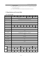
1
2
3
4
5
6
7
8
9
10
11
12
13
14
15
16
17
18
19
20
21
22
23
24
25
26
27
28
29
30
31
32
33
Transcript
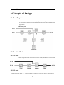
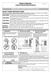
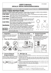
Inverter power supply user’s manual
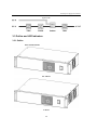
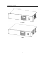
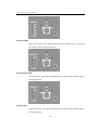
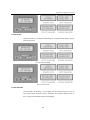
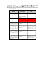
Tower model
0.5~1.5KVA
2~3KVA
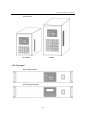
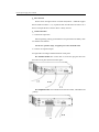
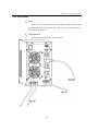
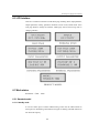
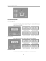
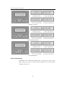
3.3.3 Rear panel
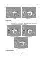
Rack standard model
Rack simplified model
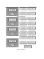
Rack simplified model 4~5KVA 48V
3-5