1
Be142
User's Manual
- August - 2014
page 2
Be142 User's Manual - Contents
1.0 Introduction ...................................................... page 3
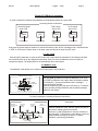
2.0 Selection of a Mode of operation ................... page 3
2.1 OFF mode ........................................................ page 3
2.2 MANUAL mode ............................................... page 3
2.3 AUTO mode .................................................... page 4
2.4 TEST mode ..................................................... page 4
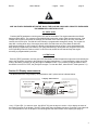
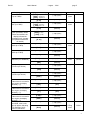
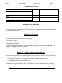
3.0 Display measurements ................................... page 4
4.0 Display messages............................................ page 6
4.10 Alarm messages ............................................ page 6
4.20 Miscellaneous messages .............................. page 7
5.0 LED indicators ................................................. page 7
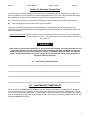
6.0 LOG Events ..................................................... page 7
7.0 Alarms, Warnings & Shutdowns .................... page 8
8.0 Automatic Periodic Test ................................. page 8
9.0 Panel & Genset builder notes ......................... page 8
10.0 Maintenance Timers Reset (Er.10) ............... page 8
Section 1.0 Introduction
The Be142 integrates a 3-Phase Automatic Mains Failure and a Generating Set controller. The Be142 provides
visual indication by means of LEDs and Display for Fuel Level, Engine & Electrical parameters, Alarms and
Status of the contactors. It features OFF-MAN-AUTO & TEST mode of operation and provides a RS485 interface
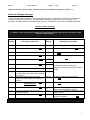
for remote control & monitoring. Figure 1 presents the panel layout. Be242 does not features serial interface.
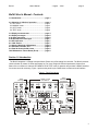
Figure 1: Front Panel layout
Alarm
acknowledge
pushbutton
Display control
& indicators
Alarm
messages
F10
A
V
Hz / R.P.M.
Engine
h / Prog.
F8
F1
F2
Manual Engine
Control
F9
F3
F4
Contactors
Control
F5
F6
F7
Operating Mode
pushbuttons & LEDs
2