1
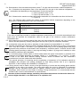
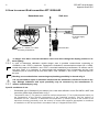
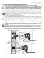
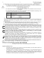
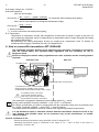
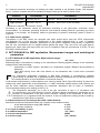
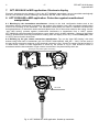
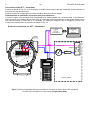
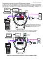
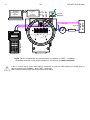
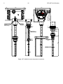
C 12 DTR.APT.ALW.03(ENG) Appendix Exi 5.5. Supply voltage min: 13.5VDC ** 5.6. Load resistance: - from 28V linear supply Ro max [Ω] = 28V – 13.5V** – (300Ω* * 0.0235A) 0.0235A - for transmitter without display back lighting from a source with trapezial or rectangular characteristic supply Ro max [Ω] = Usup. – 13.5V** 0.0235A *) barrier resistance; **) 16,5V for transmitter with display back lighting. 5.7. Temperature Temperature of transmitter’s surface with temperature of shield part as shown in figure at the point 2.3 can't surpass the admissible values of temperatures for temperature class of steam and gases according with standard EN 60079-0. Simultaneously the casing temperature should not surpass max. temperature value Ta definite for conditions power supply in Certificate Exi and p.5 of Appendix Exi. 6. How to connect Ex transmitters APT-2000ALW The transmitter and other devices in the measuring loop should be connected in accordance with the intrinsic-safety and explosion-safety regulations and the conditions for use in dangerous areas. Failure to comply the intrinsic-safety regulations can cause explosion and the resulting hazard to people. Hazardous area Safe area Ex-Milliammeter + Jumper mA _ TEST + Ro _ TEST _ +SIGNAL a Ex power supply see p.5. RD F1 F2 F3 PF RE F4 PV F4 DEF GHI @%& JKL MNO PQR +/ STU VWX YZ# . ABC 7 4 1 8 5 2 9 6 3 0 * Aplisens KAP-03Ex Communicator To measure the current in the transmitter without disconnecting the signalling circuit, connect a milliammeter to transmitter terminals TEST+, TEST-. In hazardous areas, connections to the control terminals must be made using only instruments which are permitted to be used in such areas. i The transmitter is equipped in additional communication resistor RD = 240 Ω. During normal operation terminals <SIGNAL –> and <TEST –> are shorted. RD resistor is used when you wish to communicate with the transmitter locally (from its terminals) and Ro < 240. Terminals <SIGNAL –> and <TEST –> must be opened. Transmitter electrical installation should be realised with engineering standard requirements. It is not allowed to repair or otherwise interfere with the transmitter’s electrical circuits in any way. Damage and possible repair can be assessed only by the manufacturer or another authorized party. Specific conditions of use: Allowed operating temperature range specified in point 5 Appendix Exi. Operating temperature range is restricted in the range of Ta = -20ºC to 60ºC if the device is operating in a Group I M1.