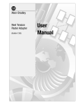
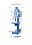
1
d&b Flying System
User Manua l
General information
d&b Flying System user manual
Version 2.0 E, July 1998
Order code D2903.E.02
Copyright by d&b audiotechnik AG 1995; all rights reserved.
The information presented in this document is, to the best of our knowledge, correct. We will however not be held responsible for the consequences of any errors
or ommissions.
Technical specifications, weights and dimensions should always be confirmed with
d&b audiotechnik AG before inclusion in any additional documentation.
In our efforts to develop and improve our products we reserve the right to
change the technical specification of our products without notice.
d&b audiotechnik tries, whenever possible, to minimise the effects of product
changes on equipment compatibility.
d&b audiotechnik AG
Eugen-Adolff- Straße 134, D-71522 Backnang, Germany
Telephone +49 / 7191 / 69 96 - 0, Fax +49 / 7191 / 95 00 00
Flying system - 2
Manual
C on tents
Introduction . . . . . . . . . . . . . . . . . . . . . .
5
1.
Flying safety
6
2.
The system design
2.1
2.2
2.2.1
2.2.2
2.2.3
2.2.4
2.3
. . . . . . . . . . . . . . . . .
. . . . . . . . . . . . .
Introduction and general description . . . . .
Components . . . . . . . . . . . . . . . . . . .
Sub bar . . . . . . . . . . . . . . . . . . . . . .
Main bar . . . . . . . . . . . . . . . . . . . . .
Spreader bar . . . . . . . . . . . . . . . . . .
Studs, cabinet fixings, chains, straps and safeties
Accessories . . . . . . . . . . . . . . . . . . . .
.
.
.
.
.
.
.
.
.
.
.
.
.
.
.
.
.
.
.
.
.
.
.
.
.
.
.
.
3. Planning and constructing the array
3.1
3.1.1
3.1.2
3.1.3
3.2
3.2.1
3.2.2
3.2.3
3.2.4
3.2.5
3.3
3.4
General . . . . . . . . . . . . . . . . . . . . . . .
Planning . . . . . . . . . . . . . . . . . . . . . . .
Load limits . . . . . . . . . . . . . . . . . . . . . .
Hanging points, loading and motor hoists . . . .
Assembling the Flying System . . . . . . . . . . .
Unpacking, safety checks and system pre-alignment
Loading and cabling the array . . . . . . . . . . .
Strapping the array . . . . . . . . . . . . . . . . .
Final alignment of the array . . . . . . . . . . . .
Raising and securing the array . . . . . . . . . . .
De-rigging and dismantling the array . . . . . . .
Safety points and procedures . . . . . . . . . . .
8
. 8
. 9
. 9
10
12
13
14
15
.
.
.
.
.
.
.
.
.
.
.
.
.
.
.
.
.
.
.
.
.
.
.
.
15
15
15
15
16
16
17
18
18
18
19
20
4. Basic array configurations . . . . . . . . . . 22
5 . C o nn e c ti ng an d wi ri n g 4 02 TO Ps a nd S U B s
5.1
5.2
Example - P1200A
with one TOP and one SUB module fitted . . . . . . 33
Example - dedicated SUB controller
with one or two modules . . . . . . . . . . . . . . . . 33
6. Care and maintenance . . . . . . . . . . . . 35
(2.0 E)
Flying system - 3
Appendices
Appendix 1
. . . . . . . . . . . . . . . . . . . . . . . . . . 40
Sub bar detent settings,
Spreader bar length and balance compensation
for 4 wide 402 systems
Appendix 2
. . . . . . . . . . . . . . . . . . . . . . . . . . 47
Setting the horizontal angle of the Sub bar
Appendix 3
. . . . . . . . . . . . . . . . . . . . . . . . . . 48
Setting the horizontal angle
between the Spreader bar and Main bars
Appendix 4
. . . . . . . . . . . . . . . . . . . . . . . . . . 49
Adjustable chains and the vertical angle
Appendix 5
. . . . . . . . . . . . . . . . . . . . . . . . . . 50
Calculating Spreader bar length for 402 arrays
Appendix 6
. . . . . . . . . . . . . . . . . . . . . . . . . . 51
Two wide flying bar, annual test & certification
Torque settings
. . . . . . . . . . . . . . . . . . . . . . . . . . 53
Specifications
. . . . . . . . . . . . . . . . . . . . . . . . . . 54
Flying system - 4
Manual
Introduction
The creation of a loudspeaker flying system which is safe, affordable
and easy to use is a far from simple task which confronts designers
with many engineering problems and conflicting demands.
The ideal flying system has yet to be built but would probably
incorporate the following key features :
–
–
–
–
–
–
–
–
–
–
Light and easy to transport
Takes up next to no truck space
Simple and quick to set-up, load and fly
Completely adjustable in every plane
Easy to adjust - even when loaded
All adjustments, angles etc. lock rigidly once set
Can be used with any type or mix of cabinets
Ultra high strength
Ultra high load carrying ability
Ultra high load safety factor
Although the ideal flying system is essentially an unattainable goal,
the practical value of the above design criteria is that they provide
a measure by which to judge the effectiveness of a given design
and so help to indicate directions for improvement.
The emergence of the 402 System as the prime d&b system for
concert applications created the need for an effective, well designed flying system - a system which would allow clusters of
loudspeakers to be swiftly, safely and accurately arrayed in the
air.
The d&b Flying system for d&b 402, 702 and F2/B1 loudspeakers
described in this manual evolved from detailed investigations and
experiments into different ways of using bars, chains and straps to
fly multiple cabinet arrays. The resulting flying system was designed and manufactured for d&b by UK specialists MAN Flying
Systems.
(2.0 E)
Flying system - 5
1. Flying safety
The dominant concern in the design and use of flying systems is
safety - the safety of the public, performers and all those who
work with flying systems.
Confusion surrounds many of the safety issues connected with the
use of flying systems in places of public entertainment. Users are
frequently left to fend for themselves trying to find practical
answers to comply with the codes and legislation covering their
working activity.
Take for example the simple question - What is an acceptable
safety factor or margin for flying components above their certified
load rating? The answer depends upon the differing views of
safety authorities. In some states in the USA a load safety ratio of
2:1 is considered acceptable whilst in Germany, a load safety ratio
of 12:1 can be required. Needless-to-say, the d&b flying system
meets the more stringent German VBG70 recommendations.
As suppliers and manufacturers of safety critical equipment d&b
and MAN take seriously their responsibility to ensure the safety of
the systems they offer users. Care has been taken in the selection
of materials, manufacturing processes and design techniques to
ensure that the flying system components are conservatively load
rated so that the structural integrity, suitability and fitness of the
flying system design for its intended use is beyond reproach. After
manufacture flying system components are carefully inspected and
assembled for despatch to an independent test station. After completion of the external tests, including a load test at twice the
certified SWL, the systems then return to the MAN factory where
all safety critical components and assemblies are stamped or engraved and the manufacturers label attached.
Note that each production version of the flying system is sold as
a complete assembly and that each major component or sub-assembly is traceable as being part of a specific, complete flying
system. Each system should always be treated as a complete system and for safety’s sake components or sub assemblies should
never be swapped between systems.
Because of the diffusion of responsibility for safety which occurs
in practical situations there is simply no way that d&b, or indeed
any supplier of flying systems, can guarantee the complete safety
of flying equipment when it is used, or more pointedly - misused.
This manual does not constitute the definitive guide to good practice
in the use of flying systems but is intended to help promote safety
awareness by providing clear information on the capabilities, adjustment and safe use of the d&b flying system. In particular the
advice and information presented here does not absolve or excuse
users from meeting the legal safety requirements and codes in
force at the time and place where the equipment is deployed.
The rigging of loudspeaker flying systems in public or working
areas should only be undertaken by specialist contractors or members of a site or touring crew with established, proven expertise
as riggers. Stage crew personnel assembling a system on site have
Flying system - 6
Manual
a duty to ensure the safe construction, adjustment and deployment
of the flying system.
The safety requirements demanded of flying system users vary
markedly from country to country and can even show great variation within a country or jurisdiction. It is thus beyond the scope
of this manual to fully inform operators of all aspects of the safe
use of the system in every conceivable situation, however, some
general points on site safety inspection procedures are worth
examining and commenting upon. At a public venue, users may
encounter a public safety officer acting on behalf of a local
licensing authority armed with the power and responsibility to
interpret the public health and safety legislation in force in that
locality. The rigour with which the statutes and codes of practice
governing public health and safety are applied or enforced depends greatly upon the interpretation of a particular situation by
individual officials. The discretion of safety officers is often enhanced by the fact that the methods of risk assessment which they
employ are generally unpublished. In general, international tour
companies using flying systems report very few problems with
safety officials since the majority of those companies, to maintain
their reputation and business, employ trained staff, use professional equipment designed to a high specification and enforce their
own stringent safety practices.
It is common practice to divide or portion out responsibility for
safety on site, for instance, a distinction is frequently made with
rigging and flying systems between what occurs above hook (the
attachment point used to raise a system) and below hook. This
artificial divide often forms a satisfactory basis for good working
practice on site. But the compartmentalisation of safety is essentially an artificial device which does not allow individuals to deny
or shirk their own responsibility. Recent examples of health and
safety legislation support the notion that responsibility for safety
is indivisible and have made it more difficult for an individual to
deny responsibility for safety in the workplace. The sobering consequence of this is that behind the legislation and codes of practice
governing health and safety the final arbiter of the right and
wrong of the decisions and course of action taken or not taken by
an individual is a court of law.
As a final emphasis in this section on safety issues, both d&b and
MAN strongly encourage the provision of proper safety training
for personnel employed by companies to use the d&b flying system. As a step towards improving knowledge of safe working
practices we recommend and urge the distribution of this document
to all users of the system. The contents of this manual must be read
and understood before using the system in any workplace or place
of public entertainment.
(2.0 E)
Flying system - 7
2. The system design
2.1
Introduction and general description
Aware of the dangers to safety and user confidence of bad design,
MAN have created a flying system which not only complies with
the stringent 12:1 load safety factor recommended under VBG70
in Germany, but a system made safer by the removal of potential
sources of user frustration. The working principles of the system
are easy to understand and the possibility of un-intentional
misassembly has been designed out as far as possible.
The flying system allows arrays of d&b 402, 702 and F2/B1
cabinets to be vertically suspended or ’flown’ from a suitable point
in the roof structure of a theatre, hall, indoor arena or other place
of public entertainment. The d&b flying system is for use only with
the 402, 702 and F2/B1 loudspeaker systems and its use with any
other loudspeaker system is not allowed.
Each cabinet is fitted with D-ring style flying studs. Columns of
cabinets are then suspended daisy chain fashion from sub bars by
pairs of steel chains with safety hooks. A webbing strap threaded
through the rear of the cabinets gives stability and control of the
vertical angle of the column. Two columns are then attached sideby-side to the underside of a Main bar suspended from the roof.
The horizontal angle of each loudspeaker column and the balance
of the Main bar are adjustable. Two or more Main bars can be
linked together at a set distance and horizontal angle by Spreader
bars.
A more detailed description of the system components follows.
Spreader bar
Main bar
calibrated barrel adjuster
Sub bar
webbing strap
11 link chain
D-ring stud
Flying system - 8
Manual
2.2
Components
The d&b flying system consists of the following components: Sub bar,
Main bar, Spreader bar, studs, chains and webbing strap.
A basic two wide set-up consists of a Main bar, two Sub bars plus
the necessary accompanying chains, studs, straps and safeties to
allow two columns of 402/702 cabinets or F2/B1 cabinets to be
flown next to each other.
The next step-up uses two of the basic set-ups described above
linked together using a the third type of bar - the Spreader bar to create a four wide system. Two Main bars linked together with
the Spreader bar allow up to 24 402/702 or 16 F2/B1 cabinets
to be flown in a single cluster.
2.2.1
S ub bar
The Sub bar allows a single column of cabinets to be flown. The
bar is a square section steel tube with a steel strip welded beneath.
At each end of the bar are holes to accept safety hook chains and
in the middle a slot for a webbing strap plus a cable anchoring
point. The outer pair of holes are used for suspending a column
of 402/702 cabinets and the inner pair are to suspend a column
of F2/B1 cabinets.
For 402/702 cabinets, MAN flying studs are fitted to the sides of
each cabinet. The top cabinet is then hung from the outer Sub bar
suspension points using short, 11 link safety hook chains. The other
cabinets are then hung underneath the top one using 23 link safety
hook chains between each cabinet’s flying studs (see p.13). The
supplied webbing ratchet strap, employed as a load restraint, is
threaded through the slot in the centre of the Sub bar and then
through the ’kelping’ bars fitted at the back of each cabinet. On
tensioning the ratchet strap, the angle between the top and second
top cabinet in each column assumes a value of 4° and the angle
between each subsequent cabinet a value of 5°. As more tension
is applied to the ratchet strap, these angles between the cabinets
remain fixed and the whole column retains a fixed curved shape
as it starts to tilt downwards.
WARN ING!
If the downward angle of the top cabinet in a column exceeds
–5°, then the webbing ratchet strap needn’t be threaded through
the upper kelping bar of the top cabinet. The maximum available
downward angle of the top cabinet when not using the top kelping
bar is approximately –15°. The strap should never be so highly
tensioned that the short chains from the Sub bar to the top cabinet
become loose and cease to be load bearing.
For columns of F2/B1 cabinets the inner Sub bar suspension points
and the 11 link safety hook chains are used for the first cabinet
(2.0 E)
Flying system - 9
with pairs of longer 47 link safety hook chains for the remaining
cabinets. The angle between each cabinet is approximately 13°.
The Sub bar described above is supplied as part of a complete
flying system and should never be used on its own, without a
Main bar, to suspend cabinets. A special version of the Sub bar
with its own hanging adapter to fly a single column of cabinets is
available to order.
2.2.2
Main bar
Fabricated from steel box section, the Main bar has a detented
track with four captively mounted sliding blocks on its underside.
Pressing a spring loaded pushbar on each sliding block frees the
block to travel along the track - releasing the pushbar locks the
block into position on the track.
Two side-by-side columns of cabinets suspended from Sub bars can
be suspended underneath a Main bar. The outer pair of blocks
provide the load bearing connection between the Main bar and
each Sub bar via a ball-jointed pin.The inner pair of blocks connect
to the top of each Sub bar via a ball-jointed link pin with a built
in screw adjuster.
Flying system - 10
Manual
WARNI NG!
Deeper columns of cabinets and more extreme vertical angles
require greater horizontal separation between each column. This
is done by moving the outer blocks further apart towards each end
of the Main bar track.
Coarse setting of the horizontal angle between two columns of
cabinets is accomplished by altering the distance between the pair
of sliding blocks for each Sub bar. The screw adjuster on the Sub bar
link pin allows fine adjustment of the horizontal angle.
Also fitted to the Main bar is a calibrated balance adjuster to
compensate for uneven load distribution if different numbers and
types of cabinets are suspended from the Sub bars. A knurled
adjuster beneath the hanging point on top of the Main bar is
shifted along a screw track in the direction of the heavier load to
shift the balance block of the bar. Main bar balance adjustment
has to be carried out with the bar unloaded.
Shackle
Suspension point hinge
Main pin
Balance block
Connector arm
Balance adjuster
Balance scale
A shackle permanently attached via a ball-joined pin to the balance block provides the Main bar suspension point. The main pin
assembly incorporates a double hinge for attaching one or two
bars.
WARN ING!
The free movement of the main pin in its socket helps protect it
against shearing forces but a badly balanced Main bar, more than
15° off balance, will force the neck of the pin against the bevelled
edge of the socket housing subjecting it to a dangerous shearing
force - never allow a Main bar to hang in a badly weighted
state. So that both balance adjustment scales in a 4 wide system
are visible from the same side there are two types of Main bar a left bar and a right bar.
(2.0 E)
Flying system - 11
2.2.3
Spre ader bar
The Spreader bar connects two Main bars at a defined distance
and horizontal angle. The exact distance apart depends on the
depth and geometry of the array and is set by adjusting the length
of the Spreader bar using the captive Tommy bar at its centre. To
aid adjustment each end of the Spreader bar has a scale calibrated in 2.5 cm increments from 140 cm to 185 cm - the distance
referred to is that between the hanging points.
Also at each end of the Spreader bar a machined slot and a
fastener bolt secured by captive pin allow it to be connected and
secured to the hinge fitted to the top of each Main bar.
The threaded section at each end of the Spreader bar has an
adjustable screw collar which connects to the balance block of
each Main bar via a floating link connector. It’s the position of the
collars on the threated section at each end of the Spreader bar
which defines the horizontal angle of each Main bars relative to
the Spreader bar.
Spreader bar link arm
A
As an aid to adjustment, calibrated scales from 0° to 60° in 5°
increments are set into each side of the threaded sections of the
Spreader bar. This mechanism for defining the horizontal angle has
the advantage that it is independent of the balance setting of the
Main bars.
Note: before fitting the Spreader bar link arm to the Main bar
connector arm, press the small spring loaded button (A) on the
connector arm. Excessive force should be avoided in order not to
break the spring load catch operated by the button.
When adding another Main bar and Spreader bar to an existing
four column wide system to create a six column wide system the
hanging point for the extra Main bar must be accurately
positioned - details are given with the later example of a six
wide system.
Flying system - 12
Manual
IMPORTANT!
2.2.4
S tuds , cabinet fixings , straps ,
chains and safeties
Built into the sides of each 402/702 cabinet and F2 & B1 cabinets
produced after 1993 are circular female stud plates which mate
with MAN D-ring flying studs - the studs are a key element of the
flying system design.
D ring flying stud and cabinet fixing
With the cabinet upright and the narrow part of the stud plate
keyhole to the top, fitting the studs is simple. The knob inside the
D-ring is pulled back to extend the locking stud which is then fitted
into the larger aperture of the keyhole, as the stud is pulled
upwards and the knob released the two components lock together.
To remove the D-ring the above fitting procedure is carried out in
reverse order.
The D-rings and stud plates provide the load bearing points for
attaching the loudspeakers to the flying system Sub bars. In the
case of the 402/702 cabinets, a pair of 11 link chains for the top
cabinet plus pairs of 23 link chains enables a column of cabinets
up to six deep to be suspended from each Sub bar.
The supplied 8 m webbing ratchet strap is used to link the cabinets
together and set the vertical angle or ’kelp’ of the column. The
strap is first of all threaded through the centre slot of the Sub bar,
through the ’kelping’ bars at the back of each cabinet before being
pulled tightly through the slot in the spindle of the ratchet mechanism and finally tensioned by cranking the ratchet handle. Above
a certain value the degree of tension applied alters the downward
tilt of the curved column. Please note that the webbing strap is
only intended to set and maintain the vertical curve and downward
angle of an array column and is not the principle load bearing
element of the design - that is the task of the chains.
Longer, adjustable chains can be supplied for use when a greater
vertical angle than the standard 5° angle between 402s/702s is
required. The length of the chains can be increased or decreased
in increments of 1.8 cm. The adjustable chains come in two types left and right. When using the chains viewed from FOH the chain
hook openings must all face to the front and the shortening device
must always be to the outside. To avoid impairing the acoustic
performance of the array, the angle between two vertically adjacent 402 TOPs should never exceed 30°.
From left to right (above): 11 link
chain, 23 link chain, left shortening
chain, right shortening chain; (below):
ratchet strap
Although the load bearing capability of the flying system is overspecified, for even greater safety an additional, secondary suspension should always be provided. Supplied with each Main bar are
a pair of steel wire safety ropes linked together at one end by a
steel O ring and terminated at their free ends with fixed shackles.
The shackles are attached to the safety lugs on top of the Main
bars whilst the O ring must be attached to a suitable, secure
overhead suspension point structurally independent of the main
rigging point(s) for the system. The wire safety ropes and their
shackles must always remain permanently attached to the Main
bars.
(2.0 E)
Flying system - 13
2.3
Accessories
A flight case is available to transport a complete four wide system
of two Main bars, four Sub bars and a Spreader bar plus safeties
and speaker cable looms.
Deployment of the flying system is eased by the ability to wheel
the flight case beneath each hook point, open the case, attach a
Main bar and lift straight from the case using a motor hoist.
Safety ropes
Correct use of the adjustable chains
Complete 2-wide system with steel wire safety ropes
E7421 Touring case flying system 4 wide
Flying system - 14
Manual
3. Planning and constructi ng the array
3.1
General
3.1.1
Planning
A site survey should be conducted before arriving on site and a
rigging plan prepared. The rigging plan should include details of
the number and type of cabinets to be flown, their position in the
array as well as the angles needed to best cover the audience
areas of the venue. The tables in the appendices and the sample
configurations in section 4 can be used to derive the system settings needed. The plan should also include the weight, intended
height and position of the load(s) to allow the venue riggers to
judge how best to attach the loaded flying system to the roof of
the building.
3.1.2
Load limits
If the full 12:1 safety margin of the flying system is required by
local safety regulations, then the roof or other structure, rigging
and the motorised chain hoists, should all be capable of supporting
loads 12 times that of a fully laden system.
The full specified load bearing capacity and safety margin of the
flying system is only available with the system and load suspended
vertically.
3.1.3
Hanging points, loading and motor hoists
The tables in section 4 allow users to determine the position of the
hanging points for different types of array set-ups. The chains or
steels suspended from the hanging points should hang vertically
with the array attached - if not, the load capability of the flying
system will be reduced by the horizontal shearing forces introduced by misalignment. Because of this factor, we urge users to
take great care in ensuring the correct positioning and correct
relationship between hanging points.
Normally a 4 wide system is flown from two separate hanging
points it is however possible for arrays 3 to 4 cabinets deep to use
a bridle chain with the Spreader bar to hang the system from just
a single point. The load ratings of the motor hoist and the roof
fixing point will of course need to be doubled for single point
suspension.
The total weight of a flying system loaded with 12 402-TOPs
including rigging and safeties is approx. 800 kg. - therefore a
chain hoist motor with a minimum load capacity of 1t is recommended. In calculating the total load for each hanging point remember to include the weight of the motor, cables and any extra
rigging - in any event it should be possible to keep the total load
on each point to under 1t.
(2.0 E)
Flying system - 15
3.2 Assembling the Flying System
Assembly and deployment of a flying array can be carried out in
five stages :
– Unpacking, safety checks and
–
–
–
–
flying system pre-alignment
Loading, strapping and cabling the array
Kelping
Checking the array alignment
Raising and securing the array
Much physical strain and effort can be avoided through careful
pre-planning, by for instance ensuring that the cabinets are set out
in the correct order on the ground ready to construct the array
one row at a time. The chain motor hoists should be used to do
the heavy lifting - the Main bars in particular can be hooked to
their hoists straight from the flight case.
3.2.1
Unpacking , safety che cks ,
and system pre-alignment
The following description assumes that the above hook rigging has
been completed and that the chain hoist motors are in position
ready and waiting for a flight cased 4 wide flying system to be
wheeled in and attached.
There should of course be sufficient clear space beneath the rigging points to unpack and set out the flying system.
Before commencing ensure that the motor hoist chains are not
twisted and that the motors hang straight and in the correct position defined on the rigging plan. The chain bucket should be
behind the Main bar and the safeties to the front.
Before lifting the Main bars from the flight case the Main bar
balance should be set. The exact setting for each bar depends
upon the mix of cabinets being deployed - details are given in an
appendix. Note that this adjustment cannot be done with cabinets
already loaded onto the bars. Each Main bar can then in turn be
securely attached to the end of each motor hook and raised a
short distance into the air so that the safety inspection described
later in the care and maintenance section can be carried out
before pre-alignment of the system.
Pre-alignment involves pre-positioning the Sub bar sliding blocks
on the Main bar track to suit the size (depth) and coverage angle
of the loudspeaker array being loaded - suitable settings are
given with the standard configurations in section 4 and in the
tables in appendix 1. The distance between each pair of Sub bar
blocks on the Main bar track defines the coarse horizontal angle
between loudspeaker columns. Typically with 402 cabinets this
setting is 11 track detents visible between the blocks. The calibrated
barrel adjuster on the Sub to Main bar link connector can then be
used for the fine adjustment of horizontal angle.
The Spreader bar length can then be set (see the table in appendix
1). Ensure that the calibration marks at each end of the bar have
the same setting and that both the sliding latch clips face the front.
Flying system - 16
Manual
The adjustable screw collars each end of the spreader bar can be
set for the desired angle between the two Main bars.
3.2.2
Loading and cabling the array
The loudspeaker array is generally constructed two rows at a time.
The first two rows of cabinets are stacked in order on the ground
beneath the suspended Sub bars of the flying system - ensure that
TOP and SUB cabinets are in the order detailed in the array plan.
The top cabinet in each column is attached to its Sub bar using a
pair of D-rings and short, 11 link chains. D-rings and standard, 23
link chains are then used to connect the second row of cabinets to
the D-rings of the first row. Ensure that the open ends of all the
chain safety hooks face forward, clips closed with the chains free
of twists.
CAUTION!
At this stage, with the first two rows of cabinets suspended just a
short distance above the ground, you should check and make any
necessary adjustments to the horizontal angles between the
speaker columns. Also at this stage, you should thread the ratchet
straps through the Sub bars and kelping bars of each speaker
column and attach the speaker multicore so that the cabinets can
be linked and connected as the array is constructed.
The system is then raised a short distance in the air to allow the
next two rows of cabinets to be wheeled beneath, tipped and
stacked. The system is then lowered with the first two rows resting
safely on top of the third and fourth rows. D-rings are then fitted
and used with standard chains to link the cabinets together. Again,
throughout the process ensure that the open ends of all the safety
hooks face forward, clips closed with the chains free of twists. As
rows of cabinets are added feed the ratchet straps through the
cabinet kelping bars and connect the speaker cables as you proceed. This process is repeated until all the rows of cabinets are
attached to the flying system.
With the final row of cabinets in place and the array raised a
short distance in the air, any errors in the pre-setting of the
horizontal balance of the flying bars should be obvious. Note that
a gross horizontal balance error can cause a Sub bar column to
flip backwards from a +15°setting to a -15° setting. Any necessary
adjustment to the horizontal balance of the bars is always carried
out with the array lowered and resting securely on the ground. For
four wide arrays as well as checking balance and angles, at this
stage any minor adjustments needed to the length of the spreader
bar due to inaccuracy in the planned positions of the rigging points
can be carried out.
A check should also be made to ensure that the chain hoist motors
operate correctly, running at the same speed so that the system
rises steadily, on the level and that the chains are not twisted and
feed unhindered into and out of the chain bucket. Ensure the chain
bucket is positioned so that it doesn’t touch the Sub bars.
(2.0 E)
Flying system - 17
3.2.3
Kelping the array
As previously indicated, whilst building the array the ratchet straps
are threaded through the Sub bars and cabinet kelping bars. Each
ratchet strap has the d&b logo printed on one side; to ensure the
correct orientation of the ratchet mechanism, the printing should
face you as the free end is fed through the Sub bar slot from
behind the array. As an array is constructed, the strap end is then
threaded through all the kelping bars on the rear of the column
starting with the top cabinet. Note though, that in some circumstances, for example when MAX cabinets are hung beneath a
column as downfills, the ratchet strap is not threaded through the
lower kelping bar of the final cabinet in the column. The standard
8 meter long ratchet strap is long enough to fit a six cabinet deep
402/702 array, although to finally thread the end of the strap into
the ratchet mechanism the bottom cabinet of the column may need
to be pulled back. Because of the limited capacity of the ratchet
mechanism, thread through as much of the strap as possible before
final tensioning. To allow later adjustment, the ratchet mechanism
is best positioned at the back of the second bottom cabinet. The
ratchet mechanism is then cranked to tension the ratchet strap, and
set the curve of each array column. Applying additional tension
sets the downward vertical angle of each column. Care should be
taken not to apply too much tension so that the top chains of the
column slacken and cease to be load bearing.
3.2.4
Final alignment of the array
Now is the time to carry out a visual check of the appearance and
alignment of the array. The proper balance of the array can be
judged by checking that the Sub bars lay parallel to the Main bar
and that both Main bars are aligned on the level.
An important point to note is that even with a properly balanced
Main bar adjacent array columns will not necessarily be perfectly
aligned in every direction. In particular, assuming that the top
cabinets of each column have the same downward angle, height
differences of some cm can be expected between columns. The
usual different mix of TOP and SUB cabinets in each column results
in different centres of gravity for the columns which cause the
differences in position. These slight differences in column position
have negligible impact on the acoustic performance of the array.
Note that this factor also means that you should not attempt to
judge how close to level the array is by looking for a neat line up
of cabinets at the bottom of the array.
Do not be tempted to try and correct these visual imperfections
by perhaps strapping adjacent columns together - this can’t be
done without affecting the Main bar balance.
3.2.5
Raising and se curing the array
When all mechanical adjustments, system checks and safety checks
are completed the array can then be raised to its operating position, locked off, and the steel safeties attached to the Main bars
secured to a separate, appropriately load rated rigging point in
the roof structure. Instruct the rigger attaching the safeties to be
Flying system - 18
Manual
careful not to disturb the balance or positioning of the array.
During the lifting operation watch out that the loudspeaker multicores do not become entangled in the array - the cables can be
taped together as the system rises. Take care that both hoist motors
operate smoothly and lift at the same rate so that the system
remains stable and level as it travels.
3.3
De-rigging and dismantling the array
De-rigging and dismantling the array is essentially a reversal of
the procedure followed to construct and fly the system and the
same cautions and safety measures apply.
The safeties to the roof structure are first of all released. No one
should be present in the area beneath the array whilst it is lowered
in an even, smooth and controlled fashion.
CAUTION!
The motors should be stopped when the array reaches a position
about half a meter from the ground and the kelping strap ratchets
released to allow the array columns to hang free vertically. Be
careful when releasing the ratchets as the sudden freeing of the
tensioned columns can be rather violent. The straps are then unthreaded from the kelping bars of the bottom two rows of cabinets
and the cable loom of multicore tails and speaker link cables
unplugged and removed. The array is then carefully lowered to
the ground with the cabinets resting in a stable manner. The studs
and chains of the two bottom rows are then removed and the
remainder of the array carefully raised a short distance into the
air, the bottom two rows are then moved out of the way and the
same process repeated for the remaining rows of the array, two
at a time.
When packing the bars into their flightcase the Sub bars should
be positioned parallel to the Main bar and the outer sliding blocks
set to the 5th or 6th detent space from the ends of the Main bar
track. These settings are the default settings for arrays three or
four cabinets deep. Do not remove the steel safeties when packing
the system - these should always be attached ready for use.
3.4
S afety points and procedures
To ensure safety, the rigging of loudspeaker flying systems in public
or working areas should only be undertaken by specialist contractors or members of a venue or touring crew with established
proven expertise as riggers.
Personnel assembling a system on site have a duty to ensure the
safe construction, adjustment and deployment of the system. Before use all the system components must be subjected to careful
and rigorous inspection and any component or assembly which has
been misused or damaged must be rejected and replaced. If there
is any doubt what-so-ever about the safety and integrity of the
system then it must not be deployed.
The safety of the system is affected by the nature of the operating
environment in which it is deployed. If for instance it is deployed
out-of-doors during heavy rain, high winds or storms then inevitably safety will be compromised.
(2.0 E)
Flying system - 19
All mechanical systems, flying systems included, eventually wear
out. The way the system is used, lack of maintenance, exposure to
water or corrosive agents, deformation or damage through improper storage or transport will all accelerate the process of deterioration and reduce the safety of the system. Owners and users
of the flying system must take all practical steps to protect the
system from deterioration.
The most important rule to follow when constructing and deploying
the system is to check, check and check again. Never assume or
take anything for granted - the most experienced and competent
system riggers can (and sometimes do) make mistakes so always
check your own work and that of the person next to you.
The chains are the load bearing supports for the suspended
cabinets; it’s important to use a short pair of chains (11 links) for
the first cabinet in each column to avoid transferring the load to
the kelping strap when the column is tilted.
For downward angles greater than the usual –5° (up to approximately –15°) the kelping strap should not be passed through the
very top kelping bar in the cabinet column. The strap however,
must be threaded through all the other kelping bars.
Always ensure that the chains are not twisted - all the safety hook
openings should face forward, clips closed. Finally, take care to
secure, dress and tidy the cable loom so that it doesn’t interfere
with the balance or free movement of the array.
It is very easy to plug in a Speakon connector so that it is not
properly locked, remember on fitting to twist the connector body
clockwise before turning the lock ring. Similarly, make sure that the
mating halves of the multipin speaker connectors are locked fully
together. It’s far easier and less hazardous to sort these things out
on the ground before the system is flown!
It helps in the case of larger arrays to have a work platform of
sufficient height available in order to avoid having someone clamber over the swaying array to carry out adjustments. Please note
that it is not possible to adjust the balance of the Main bars with
the array suspended in the air - the array must be lowered to the
ground. The horizontal setting adjusters and ratchet strap tension
for the vertical setting can however be adjusted with the system a
short distance in the air.
Before flying the system, particularly with large arrays, it can save
time and frustration later on to have a crew member temporarily
wire up the controller racks and provide a test signal to check the
speaker wiring - when the check is complete, be sure to disconnect
the loudspeakers at the racks before raising the system.
During the set-up operation and especially during all lifting operations the safety of the work crew should be paramount. Site
safety rules must be clearly understood and observed by all. One
competent, experienced person should be in charge of operating
the hoists and should issue a clear loud warning, and be satisfied
that everyone is clear of the load before operating the hoists. An
observer should be stationed with a clear view of the flying system
as it rises in order to monitor and warn if it is not rising on the
level. For their safety, all site personnel not engaged in setting up
Flying system - 20
Manual
IMPORTANT!
the array should be kept clear of the working area. As the chain
hoists operate, there is absolutely no need for anyone to be in the
area directly beneath the array or in the near vicinity of that
space.
(2.0 E)
Flying system - 21
4. Basi c array configurations
The tables on the following pages complement the information
given in TI323 and give recommended settings for the most commonly used arrays of 402 TOPS and SUBs. The flying system
settings which control Main bar balance and the horizontal and
vertical angles of the loudspeaker columns should be preset before
the cabinets are loaded. It is possible to adjust the horizontal and
vertical angles of the array with the cabinets in place but note that
the balance setting of Main bars can only be carried out with the
system unloaded. The horizontal angle between adjacent columns
of cabinets should not exceed 30° for 402 loudspeakers or 60° for
702 and F2 loudspeakers.
The tables give the appropriate settings for the Sub, Main and
Spreader bar adjusters.
The top left box of each table in the examples always shows the
left array viewed from the house. The top box second from the
right gives in metres the overall dimensions (width x height x
depth) of the array.
The next 7 rows below display in symbol form the components of
the flying system. Numbers indicating the particular settings which
have to be made for that array are also shown. The table below
details exactly what these numbers represent.
Line
Meaning
WGT kg
Weight
LEN cm
Length
ANGLE
Angle
BAL cm
Balance
DETENT
Detents
DET/SC
Detents/
Screw
ANGLE
Angle
Description
The total weight (in kg) on the hanging point
excluding the weight of the hoist motor.
The Spreader bar length (in cm) measured between
the hanging points.
The horizontal angle (in degrees) between each
Main and Spreader bar.
Main bar balance correction (in cm).
The number of free detents visible from the end of
the Main bar track to the Sub bar sliding block.
The number of free detents visible between each
outer pair of sliding blocks on the Main bar track
/ the number of turns of the screw adjuster from
its mid position (see photograph).
The horizontal angle of each column of cabinets.
Viewed from the house, a column twisted to the
left has a negative angle and one twisted to the
right a positive angle.
The lines labelled with "ROW 1-6" show the vertical angle for each
cabinet and the cabinet type. A cabinet pointing downward has a
negative angle.
Flying system - 22
Manual
0
Sub bar barrel adjuster at the "0"-position
Orientation
In the following examples the arrays are viewed from the audience
looking towards the stage, PA left array shown. A positive angle
indicates a turn to the right and a negative angle a turn to the
left.
(2.0 E)
Flying system - 23
Configuration 1
A 2-wide configuration of 4 TOPs and 4 SUBs, 65° horizontal by
40° vertical coverage.
Settings of the Sub and Main bars, weight and dimensions are
given in the following table :
Rigging plan showing the maximum dimensions (dashed box)
weight and positions of hanging points :
-1m
0m
0m
W= 485kg
1m
X
x= 0.00
y= 0.00
1m
Y
Flying system - 24
Manual
Configuration 2
A 2-wide configuration of 4 TOPs and 2 SUBs, 65° horizontal by
45° vertical coverage.
Settings of the Sub and Main bars, weight and dimensions are
given in the following table :
Rigging plan showing the maximum dimensions (dashed box)
weight and positions of hanging points :
-1m
0m
0m
W= 385kg
1m
X
x= 0.00
y= 0.00
1m
Y
(2.0 E)
Flying system - 25
Configuration 3/4
A 4-wide configuration of 6 TOPs and 6 SUBs, 95° horizontal by
40° vertical coverage.
Settings of the Sub, Main and Spreader bars, weight and dimensions are given in the following table :
Rigging plan showing the maximum dimensions (dashed box)
weight and positions of hanging points :
-1m
0m
-2m
-1m
W= 372kg
x=-1.50
y= 0.00
0m
W= 392kg
D=1.50
1m
X
x= 0.00
y= 0.00
1m
Y
Flying system - 26
Manual
Configuration 3a
A 4-wide configuration of 8 TOPs and 4 SUBs, 125° horizontal by
40° vertical coverage.
Settings of the Sub, Main and Spreader bars, weight and dimensions are given in the following table :
Rigging plan showing the maximum dimensions (dashed box)
weight and positions of hanging points :
-1m
0m
-2m
-1m
W= 392kg
x=-1.50
y= 0.00
0m
W= 392kg
D=1.50
1m
X
x= 0.00
y= 0.00
1m
Y
(2.0 E)
Flying system - 27
Configuration 6
A 4-wide configuration of 12 TOPs and 8 SUBs, 95° horizontal by
55° vertical coverage.
Settings of the Sub, Main and Spreader bars, weight and dimensions are given in the following table :
Rigging plan showing the maximum dimensions (dashed box)
weight and positions of hanging points :
-3m
-1m
0m
-2m
-1m
W= 592kg
x=-1.60
y= 0.00
0m
W= 632kg
D=1.60
1m
X
x= 0.00
y= 0.00
1m
Y
Flying system - 28
Manual
Configuration 7 ( Arena configuration)
A 6-wide configuration of 24 TOPs and 12 SUBs, 135° horizontal
by 60° vertical coverage.
Settings of the Sub, Main and Spreader bars, weight and dimensions are given in the following table :
Rigging plan showing the maximum dimensions (dashed box)
weight and positions of hanging points :
-4m
-3m
-2m
-1m
0m
1m
-2m
W= 732kg
-1m
x=-2.93
y=-1.07
D=1.66
0m
W= 739kg
x=-1.66
y= 0.00
W= 732kg
D=1.66
X
x= 0.00
y= 0.00
1m
Y
(2.0 E)
Flying system - 29
Configuration 8
A 4-wide configuration of 8 TOPs and 8 SUBs, 95° horizontal by
50° vertical coverage.
Settings of the Sub, Main and Spreader bars, weight and dimensions are given in the following table :
Rigging plan showing the maximum dimensions (dashed box)
weight and positions of hanging points :
-3m
-1m
0m
-2m
-1m
W= 482kg
x=-1.60
y= 0.00
0m
W= 502kg
D=1.60
1m
X
x= 0.00
y= 0.00
1m
Y
Flying system - 30
Manual
Configuration 9
A 6-wide configuration of 16 TOPs and 16 SUBs. 4 of the TOPs
and 4 of the SUBs provide side coverage, 155° horizontal by 60°
vertical coverage.
Settings of the Sub, Main and Spreader bars, weight and dimensions are given in the following table :
Rigging plan showing the maximum dimensions (dashed box)
weight and positions of hanging points :
-3m
-2m
-1m
0m
1m
-2m
W= 492kg
-1m
x=-2.92
y=-1.17
D=1.65
0m
W= 699kg
x=-1.75
y= 0.00
W= 732kg
D=1.75
X
x= 0.00
y= 0.00
1m
Y
(2.0 E)
Flying system - 31
Flying system - 32
Manual
5. Connecting and wiring the 402 TOPs and SUBs
A P1200A fitted with an appropriate controller module is capable
of driving two 402 TOPS or two 402 SUBS from each of its two
output channels. Each channel of the P1200L/A can drive a 4 ohm
load therefore a pair of 402 cabinets with a combined 4 ohm
impedance is a correct match. A single P1200A fitted with one 402
TOP module and one 402 SUB module can by using 4 pins of an
EP5 connector or a 4 pin Speakon drive any combination of TOP
and SUB cabinets from each output using a single speaker cable
plus a link cable between the cabinets.
5.1
Example - P12 00L/ A with one TOP
and one SU B module fitted .
Both modules are supplied with the same input signal. Output
signals for both TOP and SUB cabinets are available on each
speaker output connector of the P1200A. With the standard Speakons the TOP signal appears on 1+/1– and the SUB signal on
2+/2–. With the optional EP5s the TOP signal appears on pins 1
and 2 and the SUB signal on pins 3 and 4. Any combination of
four cabinets, TOPs and SUBs can be connected to either or both
of the P1200A speaker outputs. A stack or array of two TOPs and
two SUBs may for instance be connected to a single speaker
output and simply linked together using three short cables. Alternatively, a single TOP could be directly connected to one of the
speaker outputs and a one TOP, two SUB combination to the other
speaker output.
5.2
Example - dedicated SU B controller
with one or two modules.
In this case only the SUB pins of each of the two speaker outputs
have signal connected to them - each amplifier output is thus a
dedicated SUB amplifier. As before each speaker output is capable
of driving a two cabinet load, SUBs in this case, but if the controller
was configured as a dedicated TOP controller the connected
cabinets would of course be TOPs.
A logical approach to system wiring should take account of the
position and function of the cabinets in a complete array.
For instance in a two column wide array where the two cabinets
at the top are 402s then it makes sense to drive both cabinets from
a single P1200A output under the common control of a single 402
controller. The reasons for this approach are that the TOPs will be
placed at the top of the array in order to provide long throw
coverage - they will therefore be driven at a higher level than any
402s placed below them in the array and will probably use the
HFC feature of the controller module.
(2.0 E)
Flying system - 33
Flying system - 34
Manual
6. C are and maintenance
All mechanical systems with moving parts are subject to wear and
tear - the d&b flying system is no exception to this rule. Damage
to the system components from long term wear and tear, accident,
or the application of excessive force during set-up or adjustment
can all increase the risk of mishaps.
Since the flying system is a safety critical mechanical device it is
crucially important that the owners and users of the system adhere
to a strictly enforced and documented regime of inspection and
preventative maintenance. All personnel who set-up and use the
system must be fully informed of safety inspection procedures and
their responsibility for their implementation. The following information and advice is intended to promote the safety and well-being
of everyone, equipment owners, users, performers and of course,
the public.
The principal components of the flying system - Main bar, Sub bar
and Spreader bar are finished in a black powder coat finish. The
sliding blocks have a black chromed finish. Both types of finish
under normal usage conditions will, unless damaged, protect the
main components against rusting and corrosion. However, it should
be clearly noted that any exposure to water, including rain, or
corrosive chemicals during transport or use can weaken elements
of the system. At greatest risk are the steel rigging parts and the
fasteners used to connect or join the various elements of the system.
Frequent, thorough inspection for evidence of corrosion is strongly
recommended as is the use of a moisture displacing treatment such
as WD40 on exposed bare metal parts.
As a general rule the system should be subjected to close visual
inspection every time it is unpacked or packed. To provide a
cross-check the inspection should be carried out by more than one
person. For record purposes, and as an aid to consistency, a log
book with a printed check list of inspection steps should be packed
with the equipment so that users can check off each element of
the inspection procedure as they carry it out. The log book should
also register the details of the system such as a full parts inventory,
the serial or unique numbers stamped or engraved on the parts,
a comment section for users, details of where and when the system
has been used for shows with references to the venue rigging plan
and system details. The annual load test certificate should be
included with the log book - no system should be deployed without
a valid load test certificate.
A touring system before return to or despatch from a hire store or
warehouse should be unpacked and closely inspected. When unpacked from its flightcase as well as checking that all parts of the
system are present those examining the system should look inside
the case for indications of any liquids or corrosive materials.
During inspection between tours, the system should preferably be
set up and suspended as if it were about to be used. All moving
parts should be examined for free movement, looseness, or signs
of wear on adjacent or mating surfaces. Swivel joints should move
freely within the bounds of their intended travel. Push bars on the
(2.0 E)
Flying system - 35
sliding adjuster blocks should positively lock into place on the
detented tracks. The adjustment arms to the blocks should move
freely and the barrel adjusters should not need excessive force to
turn - if they do then the screw threads may have been damaged.
The swivel ball joint pins should move freely with 15° of rotational
movement. Look for marks or signs of wear on the bevelled surface
where the ball joint pins enter the sliding blocks and also on the
neck area of the pins themselves. The sliding blocks should move
easily along the detented track beneath the Main bar - the track
itself should be examined for signs of deformation or undue wear.
The sliding collar and screw threads on the outside of the Spreader
bar should be examined - the collar should move freely when
adjusted and positively lock into place when set.
Likewise, movement of the Spreader bar sleeve length adjuster
should not require the use of excessive force, if it does, examine
the thread for signs of wear or damage.
Note that all adjustments to the system are to be carried out by
hand - no levers, hammers, mechanical implements or other aids
should be used to apply additional force.
All fasteners including the fixings for the O link, Spreader bar to
Main bar fittings and those on the balance leadscrew and sliding
blocks should be checked for security and tightness - see the
specification for the recommended torque settings.
Other parts such as studs, shackles, chains and safety steels should
be carefully examined for signs of wear or deformation and also
checked to ensure that they haven’t been swapped for other parts
on-site, make certain that they are certified - stamped or engraved
with the appropriate SWL. The condition of the safety chains
linking the Sub bars to the Main bar should also be carefully
inspected - the fixings used to attach the chains to the bars should
pivot freely.
A close visual inspection should be made of the entire surface of
the bars - points to look out for are any signs of buckling, twisting
or other deformation.
The surface and the weld seams of the bars should also be clean
and show no signs of corrosion or erosion and the manufacturers
labels and engraved marks should not have been tampered with.
Needless-to-say if any defects are discovered during inspection
which cast doubt on the safety of the flying system it should not
be deployed.
Flying systems set up in permanent installations pose fewer safety
problems than touring or mobile systems, none-the-less, regular
safety inspections of fixed or semi-fixed systems based upon the
above guidance should also be undertaken.
Those whose approach to the use of flying systems is firmly rooted
in the distinctly pressured working environment of the concert tour,
and who view dealing with structured, documented inspection routines as a waste of precious set-up time would be well advised to
check the requirements and limitations of their public liability insurance.
Flying system - 36
Manual
(2.0 E)
Flying system - 37
Flying system - 38
Manual
Append ices
(2.0 E)
Flying system - 39
A ppen dix 1
Sub bar detent settings,
Spreader bar length
and balance compensation
for 4 wide 402 systems
The following four tables give the recommended Sub bar detent
positions and Spreader bar length for different depths of 4 column
wide 402 arrays.
The position of the outer Sub bar sliding blocks on the Main bar
track and the length of the Spreader bar adjust the horizontal
spacing of the array as the vertical tilt angle (downward or
upward) and the depth of the array is altered. The Sub bar detent
settings refered to in the tables are the number of Main bar track
detents between each end of the track and each outer sliding
block.
The first tables give the standard settings valid only for 4 wide 402
arrays 1-6 cabinets deep where the top cabinet of each column is
set to a vertical tilt angle of between 0° to –5°.
As the depth of the standard array is increased the available range
of vertical tilt diminishes - the top cabinet of a 5 deep array can
have a vertical tilt of between 0° to –10° and a 6 deep array in
between 0° to –3°.
The range of tilt vertical angles from the standard table should suit
most cases as it would be unusual for the top cabinet in an array
to require a downward angle greater than –5°. In the case of a
5/6 deep array the bottom cabinet would have a 24°/29° downward angle - close to our recommended maximum.
The remaining tables give recommended settings for vertical tilt
angles between –5° and –10°.
Note that the vertical tilt angle refered to above is not the vertical
dispersion or coverage of the array - that is a fixed value dependent on the length of the chains used between each cabinet in the
columns. The vertical tilt angle is variable within a given range and
is controlled by the degree of tension applied using the kelping
strap.
Setting the Main bar balance is normally only necessary when
different types and/or numbers of cabinets are suspended from
each Sub bar attached either side of the central balance point of
a Main bar. In the case of 402 cabinets the balance of a Main bar
will alter due to the different weights of the TOP and SUB cabinets
and their position in the array to the left or right of the Main bar
hanging point.
If for instance 3 402 TOPs were suspended from one Sub bar and
3 402 SUBs from the other Sub bar then because of the weight
difference between the two types of cabinets the Main bar will tilt
away from the level. The information in the following tables allows
these factors to be taken into account and a preset balance compensation setting to be applied before loading and lifting an array.
Flying system - 40
Manual
The following tables only apply when the same number
of cabinets are hanging from each Sub bar.
In each of the balance compensation tables the horizontal axis of
the table refers to the number of TOPs in the column on the Sub
bar to the left of the Main bar hanging point and the vertical axis
to the number of TOPs in the column on the Sub bar to the right
of the Main bar hanging point.
The numbers in the table give in cm the distance the Main bar
hanging point should be shifted to compensate for unequal loading. Balance compensation adjustment is always applied towards
the heavier side of the Main bar load.
Example:
2 Sub bars hang from a Main bar, the one on the left has 3 402TOPs and the bar on the right has 2 402- SUBs and 1 402-TOP,
the array is 3 cabinets deep with a vertical angle of –3° of the
top cabinet. Refering to table 1.3 which gives the balance compensation settings for use with arrays 3 cabinets deep:
Since there are 3 TOPs on the left refer to the horizontal axis of
the table marked left to the column headed 3. The correction
factor is the value found at the intersection with the vertical, right
side value, which in this case is 1, giving a balance compensation
factor of 2.0 cm.
(2.0 E)
Flying system - 41
Balance compensation for arrays
with an angle of 0° to –5° of the top cabinet
Table 1.0
0° to –5° vertical tilt settings
Array depth
Sub bar detent
setting
Spreader bar
length
1
8
145 cm
2
7
150 cm
3
6
155 cm
4
4
160 cm
5
3
170 cm
6
0
175 cm
Table 1.1
Balance compensation for arrays 1 cabinet deep
left
0
0
1
0
2.3
0
1
Table 1.2
Balance compensation for arrays 2 cabinets deep
left
0
0
1
2
0
1.5
2.8
0
1.4
1
2
0
Table 1.3
Balance compensation for arrays 3 cabinets deep
left
0
0
1
2
3
0
1.1
2.1
3.1
0
1.0
2.0
0
1.0
1
2
3
Flying system - 42
0
Manual
Table 1.4
Balance compensation for arrays 4 cabinets deep
left
0
0
1
2
3
4
0
1.0
1.9
2.7
3.6
0
0.9
1.8
2.6
0
0.9
1.7
0
0.8
1
2
3
4
0
Table 1.5
Balance compensation for arrays 5 cabinets deep
left
0
0
1
2
3
4
5
0
0.8
1.6
2.4
3.1
3.8
0
0.8
1.5
2.3
3.0
0
0.8
1.5
2.2
0
0.7
1.4
0
0.7
1
2
3
4
5
0
Table 1.6
Balance compensation for arrays 6 cabinets deep
left
0
1
2
3
4
5
6
(2.0 E)
0
1
2
3
4
5
6
0
0.8
1.5
2.3
3.0
3.7
4.3
0
0.8
1.5
2.2
2.9
3.6
0
0.7
1.4
2.1
2.8
0
0.7
1.4
2.1
0
0.7
1.4
0
0.7
0
Flying system - 43
Balance compensation for arrays
with an angle of greater than –5° down to
–10° of the top cabinet
Table 2.0
–5° to –10° vertical tilt settings
Array depth
Sub bar detent
setting
Spreader bar
length
1
8
145 cm
2
7
150 cm
3
5
160 cm
4
3
165 cm
5
0
180 cm
6
–
–
Table 2.1
Balance compensation for arrays 1 cabinet deep
left
0
0
1
0
2.3
1
0
Table 2.2
Balance compensation for arrays 2 cabinets deep
left
0
0
1
2
0
1.5
2.8
0
1.4
1
2
0
Table 2.3
Balance compensation for arrays 3 cabinets deep
left
0
0
1
2
3
0
1.2
2.3
3.3
0
1.1
2.1
0
1.0
1
2
3
Flying system - 44
0
Manual
Table 2.4
Balance compensation for arrays 4 cabinets deep
left
0
0
1
2
3
4
0
1.0
1.9
2.8
3.7
0
1.0
1.9
2.7
0
0.9
1.8
0
0.9
1
2
3
4
0
Table 2.5
Balance compensation for arrays 5 cabinets deep
left
0
0
1
2
3
4
5
0
0.9
1.8
2.7
3.5
4.3
0
0.9
1.7
2.6
3.4
0
0.9
1.7
2.5
0
0.8
1.6
0
0.8
1
2
3
4
5
0
Table accuracy
The accuracy of the above tables is limited by component and
material tolerances which affect the actual weight of the cabinets
so that the balance compensation setting needed in practice can
differ by up to 10% in the worst case from that predicted in the
tables.
(2.0 E)
Flying system - 45
Calculating the balance compensation
For cases not covered by the tables, for instance a different number of cabinets in both columns or 402s combined with other types
of cabinets such as F2/B1s, the required balance compensation is
easy to calculate.
(weight of left cabinets – weight of right cabinets)
Balance compensation = -------------------------------------------------- (51 cm – 2 x detents)
(total cabinet weight + 45 kg)
The weights used in the caculation should include not just the
cabinet weights but the weight of the chains, studs and other
rigging. With rigging the 402-TOP weighs 60kg and the 402- SUB
50kg the F2 weighs 82kg and the B1 67kg.
Example:
2 402-SUBs and 2 402-TOPs are hung on the left side of a Main
bar and 3 402-TOPs on the right side
The combined weight of the 2 SUBs and 5 TOPs is :
2 x 50 kg + 5 x 6 0 kg = 400 kg
Adding the 45 kg weight of the Main bar plus straps gives a total
weight of 445 kg.
The weight of the left cabinets =
2 x 50 kg + 2 x 6 0 kg = 220 kg
The weight of the right cabinets =
3 x 6 0 kg = 18 0 kg.
For a 3 deep array the table 1.0 for Sub bar settings recommends
a setting of 6 detents.
The balance compensation is calculated as:
220 kg – 18 0 kg
40 kg
(51cm - 6x2cm) x -----------------= 39 cm x --------- = 3.505... cm
445 kg
445 kg
Giving a balance compensation setting of 3.5 cm.
Flying system - 46
Manual
Appendix 2
Setting the horizontal angle of the Sub bar
Two factors determine the horizontal angle between Sub bar and
Main bar, the distance (number of detent spaces) between the pair
of sliding blocks for each Sub bar and the length (number of turns)
set on the barrel adjuster. The basic setting, with the Sub bar
parallel to the Main bar is 12 detent spaces between the blocks
and the barrel adjuster set to its 0 reference position. Fully turning
the barrel adjuster away from its 0 reference position to its MAX
position sets the Sub bar to a 15° angle.
With 402 cabinets the horizontal angle between columns in normal
use will not exceed 30° the appropriate angle can be achieved by
reducing block spacing from 12 to 11 detent spaces so that the
barrel adjuster now gives an adjustment range of 16°- 30°. Note
that the angle between Main and Sub bar will remain constant as
long as the size of the gap between the blocks remains fixed.
Barrel adjuster at 0 position (reference)
When an angle greater than 15° is required, for instance with F2s,
the number of detent spaces between the Sub bar blocks is decreased and the length of the barrel adjuster set if an intermediate
angle is desired.
We recommend that the horizontal angle of the columns is always
verified visually during assembly. Factors which can disturb the
horizontal angle of a column include a badly balanced Main bar
or a trapped cable. With 402s if the rear angled panels on the
side of the cabinet are parallel then the columns are correctly
spaced at a 30° angle.
(2.0 E)
Flying system - 47
A ppen dix 3
Setting the horizontal angle between
the Spreader bar and Main bars
The mechanics for setting the horizontal angle of Main bars
relative to the Spreader bar used to link them together are quite
straight forward.
The coarse setting of the horizontal angle is set by positioning an
adjustable collar which connects to the top of the Main bar below.
The collar for the link to each of the two Main bars can be
accurately positioned using a scale set into the threaded section
at the end of each Spreader bar. Each scale is calibrated in 5°
increments between 0° and 60°.
Recommended angles for 4 wide and 6 wide systems are given in
chapter 4. Since the bar link pins connect to the balance block on
top of each Main bar changing the horizontal angle of a Main bar
doesn’t affect its balance. If the Main bar is badly balanced to
begin with it can happen that when altering the horizontal angle
the bar can suddenly flip to a backwards facing position - easily
corrected by pulling and twisting the bar towards the front.
Flying system - 48
Manual
Appendix 4
Adjustable chains and the vertical angle
The 23 link standard chains for the 402s produce a 5° vertical
angle between the cabinets. Using 47 link adjustable chains (shorteners) allows a greater vertical angle between cabinets. Set to 19
links (the 19th link counted from the bottom placed on the shortener hook) this gives a chain length which is equivalent to a
standard chain.
By placing the 18th link of the chain on the shortener you then get
an angle of 1° to 2° between a pair of 402s. To do this first attach
the bottom hook to its stud then release the top stud, place the
18th link on the shortener hook then hook on the chain and
re-attach the top stud.
Each link from the 20th to the 24th placed on the shortener hook
gives a 5° increase in the angle between cabinets. The 24th link
results in the maximum permissable vertical angle of 30° any angle
greater than this makes no sense acoustically.
When using adjustable chains the shortening hook should face out,
this means that different shorteners (left & right) have to be used
for each side of the cabinet.
The standard chains for F2/B1 cabinets have 47 links giving an
approx. 13° vertical angle between two F2s - adjustable (longer)
chains should not be used.
E6525
Shortening chain
47 links, right
(2.0 E)
E6526
Shortening chain
47 links, left
Flying system - 49
A ppen dix 5
Calculating Spreader bar length
for 402 arrays
In the case of 4 column wide arrays of less than 100° horizontal
dispersion adjusting the length of the Spreader bar makes it
possible to hang the cabinet columns closer to each other.
For an array it’s possible to calculate a setting for the length of
the Spreader bar (this method also works for narrower coverage
arrays).
The Sub bars are positioned a little closer by selecting a slightly
larger detent spacing than that suggested in the tables of appendix
1 for the depth of array being used. The gap between the flying
studs of the cabinets in the 2 centre columns is measured . The
value for the gap (D in cm.) is used in the following formula to
arrive at the length of the Spreader bar.
Spreader bar length = 172 cm + D – (4 cm x detent spaces)
Example:
For an array 3 cabinets deep table 1.0 in appendix 1 recommends
6 detent spaces. For a narrower setting the Sub bars blocks are
moved one detent space towards the centre of the Main bar tracks
i.e. detent position 7. A 5 cm gap is measured between the centre
columns of the array - this is the value for D. Using the formula
for Spreader bar length:
Spreader bar length = 172 cm + 5 cm – (4 cm x 7) = 139 cm
Flying system - 50
Manual
Appendix 6
Two wide flying bar
Annual test & certification
Every d&b flying system is supplied with a proof load test certificate valid for a period of one year from the date of issue. Since
no flying system should ever be deployed unless covered by a valid
proof load test certificate, the supplied certificate will need to be
renewed annually.
In addition to the regular care and maintainance regime detailed
above, every d&b flying system should ideally be returned once a
year to MAN Flying Systems for inspection, proof load test and
re-certification. Where this is not possible, the flying system can
instead be submitted to an independent test organisation for inspection, proof load test and re-certification.
The proof load test procedure outlined below should only be
carried out by an experienced test engineer, qualified and accredited to inspect, test and issue safety certificates for mechanical
lifting equipment. The test applies only to the two wide flying bar,
integral Sub bars and load bearing elements of the ‘transformer
style’ loudspeaker flying system assembly manufactured by MAN
Flying Systems. Flying bars manufactured by MAN Flying Systems
all have an attached manufacturers identity plate. The serial number, date of manufacture and safe working load of the bar are all
detailed on the identity plate. No proof load test should be carried
out on any flying bar presented as part of a d&b flying system
which does not carry the manufacturers identity plate. No proof
load test should be carried out on any flying bar presented as part
of a d&b flying system where the details on the attached manufacturers identity plate have been defaced or altered.
Proof load test
The proof load test verifies the structural integrity of the two wide
flying bar, integral Sub bars and load bearing elements of the
‘transformer style’ loudspeaker flying system assembly manufactured by MAN Flying Systems . One of the following test methods
is selected and used:
– proof load applied as four individual live loads.
– proof load applied as two paired loads.
– proof load applied as a single tensile load
For all test methods:
On each two wide bar, move the Sub bar load bearing blocks to
the ends of the detented track. Position the Sub bar angle adjuster
blocks to align the Sub bars with the two wide bar. Set the balance
correction adjuster to its "0" position.
(2.0 E)
Flying system - 51
Four load method
– Suspend the two wide bar of a flying assembly by its lifting point
–
–
–
–
–
–
from an overhead lifting source.
Attach four 625.0 kg weights, one to each outer hole on the
Sub bars (the flying system has a 1.25 Tonne SWL - twice 1.25
Tonne divided by four equals 625.0 kg).
Apply a small amount of tension and check that the assembly
is correctly arranged.
When satisfied that everything is in order increase the tension
until all four weights are airborne.
Inspect the whole flying assembly for any visible signs of stress
or distortion.
The proof load should be applied for a minimum of one minute.
When complete, slowly lower the assembly, remove all the
weights and then remove the flying system from the lifting
source.
Two load method
This follows the same steps as the above ‘Four load method’ except
that at step 2 in the procedure, instead of using four individual
loads, a single equally bridled 1.25 Tonne load is attached to each
of the two Sub bars (this produces an additional load on the Sub
bars but one which is within their design specification).
Single live load or tensile method
Two flying system assemblies are linked together and tested using
this method. Suspend one flying system by its lifting point from an
overhead lifting source. Using shackles and/or hooks attach and
suspend another flying system upside down beneath the first one.
– Attach a single 2.5 Tonne load to the free suspension point
(Unilock shackle) of the lower flying system and proceed from
step 3 of the above four load method. The single live load
method may also be applied using a vertical or horizontal test
machine.
On completion of the inspection and proof load test a test certificate listing the serial numbers of the flying system assemblies
successfully tested may be issued. Note that no additional marks
or stamps should be applied to the flying system itself.
Test Engineers carrying out the proof load test procedure outlined
above are advised to contact MAN Flying Systems for clarification
of any of the test details which they do not fully understand.
Flying system - 52
Manual
(2.0 E)
Flying system - 53
Spe cifications
Dimensions and weights
The length of a Sub bar at 69 cm matches the width of a 402
cabinet fitted with flying studs. The length of the Main bar on its
own is 125 cm. The maximum overall length of a Main bar fitted
with two Sub bars is 140 cm. The height of the combined bars is
40 cm to the screw adjustable balance block, 53 cm to the centres
for the bar fastener and 59 cm to the 10t shackle. Total height
with the shackle is 67 cm. The weight of the Main bar plus Sub
bars (without safety steel ropes) is 41 kg. The Spreader bar weighs
14 kg and has an overall length adjustable from 141 to 181 cm.
The safety steel ropes weigh 4 kg. The cabinet weights including
studs and chains are: 402-TOP - 60kgs, 402-SUB - 50kgs, 702-LS
- 57kgs. The 3kg weight difference between the 402-TOP and the
702-LS has only a marginal effect on the balance settings.
Flying system - 54
Manual
Bescheinigung der Baumusterprüfung nach VBG70
Die Bescheinigung gilt für das in diesem Handbuch beschriebene
d&b Flugsystem, bestehend aus den Komponenten
Z5070 1-wide
Z5073 2-wide
Z5077 3-wide
Z5072 Spreader Bar
Z5079 Telescopic Spreader Bar
sofern diese mit den d&b Lautsprechersystemen 402-TOP, 402SUB, 702- LS, F2-LS, B1 und MAX benutzt werden, die über entsprechende Aufnahmevorrichtungen (Stud Plate) für MAN Flying
Studs (Z5040) verfügen.
Auch die Ketten E6520, E6521 und E6522, sowie der E6510 Zurrgurt und der Z5040 MAN Flying Stud erfüllen als integraler Bestandteil des Flugsystems die Vorschriften der VBG70 (GUV6.15),
sofern sie innerhalb des d&b Flugsystems eingesetzt werden.
Hiermit wird bestätigt, daß die oben genannten Produkte der Firma d&b audiotechnik AG den Vorschriften der UVV "Veranstaltungs- und Produktionsstätten
für szenische Darstellungen" (VBG70 [GUV6.15] in der
Fassung vom 1.4.1998) entsprechen.
Die Erklärung wird verantwortet durch die Firma d&b
audiotechnik AG, Backnang.
Translation:
This declaration applies to the following d&b flying system components described in this manual
Z5070 1 wide Z5073 2 wide Z5077 3 wide Z5072 Spreader bar
Z5079 Telescopic bar
provided that these are used with d&b 402-TOP,402-SUB,702LS,F2-LS,B1 and MAX loudspeakers fitted with stud plates specified
for use with MAN Flying Studs (Z5040).
Chains E6520, E6521, and E6522 together with ratchet strap E6510
and Z5040 flying studs are integral load connector components
covered by the requirements of VBG70 (GUV 6.15) provided they
are used as part of a d&b flying system.
We hereby declare that the above listed products supplied by d&b
audiotechnik comply with the relevant requirements of UVV "Veranstaltungs- und Produktionsstätten für szenische Darstellungen"
(VBG70 [GUV6.15] as of 1.4.1998)
d&b audiotechnik AG of Backnang accepts responsibility for this
declaration.
(2.0 E)
Flying system - 55
d&b audiotechnik AG, P.O. Box 1325, D-71503 Backnang, Germany, Tel. +49/7191/9669-0, Fax +49/7191/9500-00