1
7: DEVICE ADDRESSES
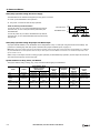
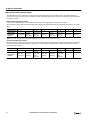
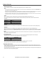
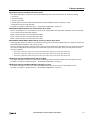
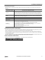
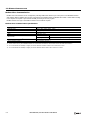
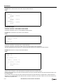
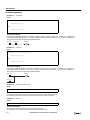
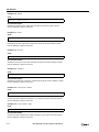
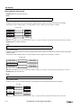
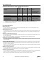
D8092-D8095 Default Gateway (Current Data) Read only
Default gateway of the SmartAXIS is stored in the special data registers as shown below.
Example) Default gateway: aaa.bbb.ccc.ddd
D8092=aaa, D8093=bbb, D8094=ccc, D8095=ddd
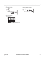
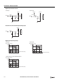
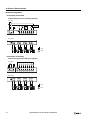
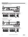
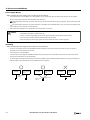
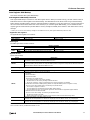
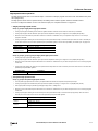
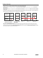
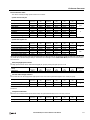
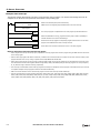
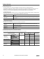
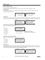
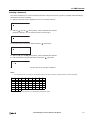
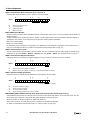
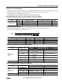
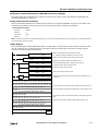
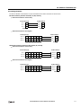
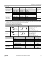
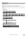
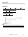
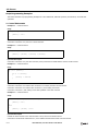
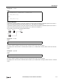
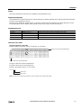
D8104 RS232C Control Signal Status (Port 2 and Port 3) [Ladder program only]
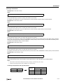
RS232C control signal status of port 2 and port 3 is stored in D8104.
This function cannot be used when FBD program is selected as the programming language.
Bit
15
Bit
8
Bit
7
D8104
3
Bit
2
1
Bit
0
0
0
0
0
Port 3
Port 2
00:
01:
10:
11:
Both DSR and DTR are off
DSR is off, DTR is on
DSR is on, DTR is off
Both DSR and DTR are on
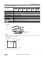
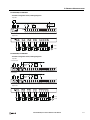
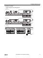
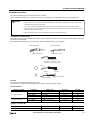
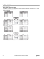
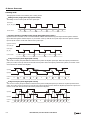
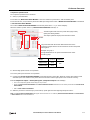
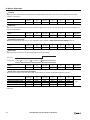
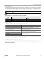
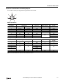
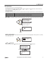
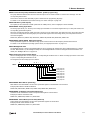
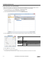
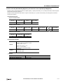
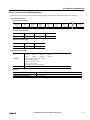
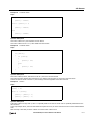
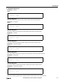
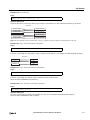
D8105 RS232C DSR Input Control Signal Option (Port 2 and Port 3) [Ladder program only]
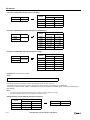
Special data register D8105 is used to control data flow between the SmartAXIS RS232C port 2 and port 3 and the remote terminal
depending on the DSR (data set ready) signal sent from the remote terminal.
Bit
15
Bit
8
Bit
7
D8105
5
4
Bit
3
2
1
Bit
0
0
0
0
0
0
0
Port 3
Port 2
000:
001:
010:
011:
100:
Others:
DSR is not used for data flow control
When DSR is on, SmartAXIS can transmit and receive data
When DSR is off, SmartAXIS can transmit and receive data
When DSR is on, SmartAXIS can transmit data (busy control)
When DSR is off, SmartAXIS can transmit data
Same as 000
This function cannot be used when FBD program is selected as the programming language.
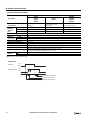
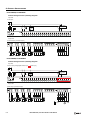
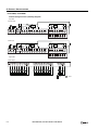
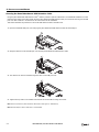
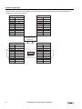
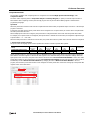
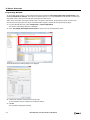
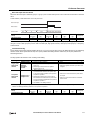
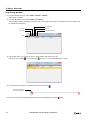
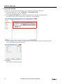
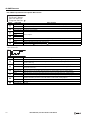
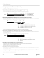
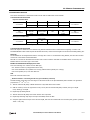
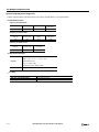
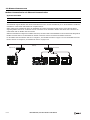
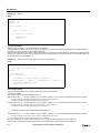
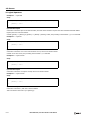
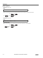
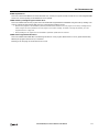
D8106 RS232C DTR Output Control Signal Option (Port 2 and Port 3) [Ladder program only]
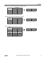
Special data register D8106 is used to control the DTR (data terminal ready) signal to indicate the SmartAXIS operating status or
transmitting/receiving status.
This function cannot be used when FBD program is selected as the programming language.
Bit
15
Bit
8
Bit
7
D8106
3
Bit
2
1
Bit
0
0
0
0
0
Port 3
00:
01:
10:
11:
Port 2
DTR is on (off while SmartAXIS is stopped)
DTR is off
DTR is on while SmartAXIS can receive data (auto switching)
Same as 00
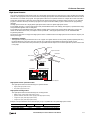
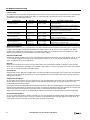
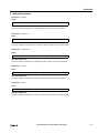
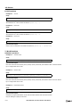
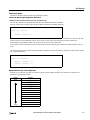
D8110-D8121 Connection (1 through 3) Connected IP Address
The IP address of the remote host accessing connection 1 through 3 is stored in special data registers.
Example) Connection 1 Connected IP Address: aaa.bbb.ccc.ddd
D8110=aaa, D8111=bbb, D8112=ccc, D8113=ddd
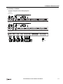
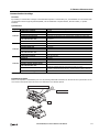
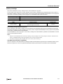
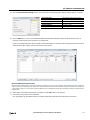
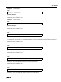
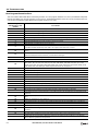
D8130-D8132 Connection Connected Port Number
When connections are established with other network devices, the port numbers of the connected network devices are stored in
these special data registers.
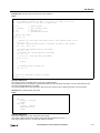
For FBD, a linear transformation can be configured for the analog input (AI). Even when a linear transformation is configured for
AI, the special data registers store the analog values (0 to 1000) before the linear transformation.
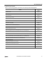
D8130 : Connection 1 Connected Port Number
D8131 : Connection 2 Connected Port Number
D8132 : Connection 3 Connected Port Number
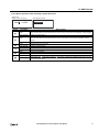
7-14
SMARTAXIS PRO/LITE USER'S MANUAL FT9Y-B1378