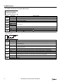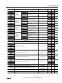
1
FT9Y-B1378(4)
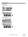
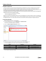
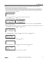
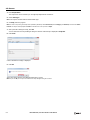
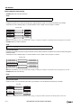
SAFETY PRECAUTIONS
Read the SmartAXIS Pro/Lite User’s Manual to ensure correct operation before starting installation, wiring, operation, maintenance, and
inspection of the SmartAXIS.
All SmartAXIS modules are manufactured under IDEC’s rigorous quality control system, but users must add a backup or failsafe provision to the
control system when using the SmartAXIS in applications where heavy damage or personal injury may be caused, in case the SmartAXIS should
fail.
In this user’s manual, safety precautions are categorized in order of importance:
Warning
Warning notices are used to emphasize that improper operation may cause severe personal injury or death.
The SmartAXIS is not designed for use in medical equipment, nuclear power, railways, aviation, passenger vehicle equipment, or similar
applications requiring a high degree of reliability and safety. The SmartAXIS should not be used for such applications.
When using the SmartAXIS in applications (not described above) that require a high degree of reliability in terms of functionality and precision,
appropriate measures such as failsafe mechanisms and redundant mechanisms must be taken for the system containing the SmartAXIS.
Emergency stop and interlocking circuits must be configured outside the SmartAXIS.
If relays or transistors in the SmartAXIS output circuits should fail, outputs may remain at on or off state. For output signals which may cause
serious accidents, configure monitor circuits outside the SmartAXIS.
The SmartAXIS self-diagnostic function may detect internal circuit or program errors, stop programs, and turn outputs off. Configure circuits
so that the system containing the SmartAXIS is not jeopardized when outputs turn off.
Turn off power to the SmartAXIS before installation, removal, wiring, maintenance, and inspection of the SmartAXIS. Failure to turn power off
may cause electrical shocks or fire hazard.
Special expertise is required to install, wire, program, and operate the SmartAXIS. People without such expertise must not use the SmartAXIS.
Install the SmartAXIS according to the instructions described in SmartAXIS Pro/Lite user's manual. Improper installation will result in falling,
failure, or malfunction of the SmartAXIS.
Caution
Caution notices are used where inattention might cause personal injury or damage to equipment.
The SmartAXIS is designed for installation in a cabinet. Do not install the SmartAXIS outside a cabinet.
Install the SmartAXIS in environments described in the SmartAXIS Pro/Lite user's manual. If the SmartAXIS is used in places where the
SmartAXIS is subjected to high-temperature, high-humidity, condensation, corrosive gases, excessive vibrations, or excessive shocks, then
electrical shocks, fire hazard, or malfunction will result.
The environment for using the SmartAXIS is “Pollution degree 2.” Use the SmartAXIS in environments of pollution degree 2 (according to IEC
60664-1).
Prevent the SmartAXIS from falling while moving or transporting the SmartAXIS, otherwise damage or malfunction of the SmartAXIS will result.
Wiring must use lead sizes that are appropriate for the applied voltage and current. Terminal screws must be tightened with the prescribed
tightening torque.
Prevent metal fragments and pieces of wire from dropping inside the SmartAXIS housing. Put a cover on the SmartAXIS modules during
installation and wiring. Ingress of such fragments and chips may cause fire hazard, damage, or malfunction.
Use a power supply of the rated value. Use of a wrong power supply may cause fire hazard.
Use an IEC 60127-approved fuse on the power line outside the SmartAXIS. This is required when equipment containing the SmartAXIS is
destined for Europe.
Use an IEC 60127-approved fuse on the output circuit. This is required when equipment containing the SmartAXIS is destined for Europe.
Use an EU-approved circuit breaker. This is required when equipment containing the SmartAXIS is destined for Europe.
Make sure of safety before starting and stopping the SmartAXIS or when operating the SmartAXIS to force outputs on or off. Incorrect operation
of the SmartAXIS may cause machine damage or accidents.
Do not connect the ground wire directly to the SmartAXIS. Connect a protective ground to the cabinet containing the SmartAXIS using an M4 or
larger screw. This is required when equipment containing the SmartAXIS is destined for Europe.
Do not disassemble, repair, or modify the SmartAXIS modules.
The SmartAXIS contains electronic parts and batteries. When disposing of the SmartAXIS, do so in accordance
with national and local regulations.
SMARTAXIS PRO/LITE USER'S MANUAL FT9Y-B1378
Preface-1
ABOUT THIS MANUAL
This user’s manual describes functions, specifications, installation, and operation basics of the SmartAXIS. Also included is
information on the powerful communications tools of the SmartAXIS, as well as troubleshooting procedures.
Chapter 1: General Information
General information about the SmartAXIS, features, brief description on special functions, and various system setup configurations
for communication.
Chapter 2: Product Specifications
Specifications of SmartAXIS, optional adapters, and cartridges.
Chapter 3: Installation and Wiring
Methods and precautions for installing and wiring the SmartAXIS.
Chapter 4: Operation Basics
General information about setting up the basic SmartAXIS system for programming, starting and stopping SmartAXIS operation, and simple
operating procedures. Everything from creating a user program using WindLDR on a computer to monitoring the SmartAXIS operation.
Chapter 5: Special Functions
Stop/reset inputs, run/stop selection at memory backup error, and keep designation. Also included are high-speed counter,
frequency measurement, catch input, interrupt input, timer interrupt, input filter, user program protection, daylight savings time,
network settings, and many more special functions.
Chapter 6: HMI Function
HMI function on the SmartAXIS Pro by using the LCD and operation buttons on the SmartAXIS.
Chapter 7: Device Addresses
Device addresses available for the SmartAXIS to program basic and advanced instructions. Special internal relays and special data
registers are also described.
Chapter 8: Instructions Reference
List of basic and advanced instructions to program the SmartAXIS.
Chapter 9 through Chapter 11: Maintenance Communication, User Communication Instructions, Modbus
Communication
Various communication functions such as user communication and Modbus communication.
Chapter 12: Remote I/O
Remote I/O communication to increase the number of inputs and outputs by connecting other SmartAXIS as remote I/O slaves over Ethernet.
Chapter 13: Script
Programming complicated processing with script language using conditional branching, logical operations, arithmetic operations, and functions.
Chapter 14: Troubleshooting
Procedures to determine the cause of trouble and actions to be taken when any trouble occurs while operating the SmartAXIS.
Appendix
Additional information about type numbers, system software upgrade, and USB driver installation.
Index
Alphabetical listing of key words.
Publication history
March 2013
August 2013
October 2013
December 2013
August 2014
First Edition
Second Edition
Third Edition
Fourth Edition
Fifth Edition
Trademarks
SmartAXIS is a trademark of IDEC Corporation.
Regarding laws and compatible standards
This product adheres to the laws and compatible standards of all countries involved, as shown below.
European laws and standards
This product complies with the following EU directives.
Low Voltage Directive (Directive 2006/95/EC)
EMC Directive (Directive 2004/108/EC)
IEC/EN 61131-2: 2007 (excluding the Lite digital I/O status indicators)
To comply with these directives, this product has been designed and evaluated on the basis of the following international and
European standard.
For details on the compatible standards and EU Directives, contact the distributor from which you purchased this product or visit our web site.
North America laws and standards
This product complies with the following standards.
UL508
CSA C22.2 No.14
Marine standards
This product is certified by the following classification societies. (FT1A Version V130 or later, system software version V2.10 or
later)
- ABS (American Bureau of Shipping)
- DNV (Det Norske Veritas, Norwegian classification society)
- LR (Lloyd's Register)
- NK (Nippon Kaiji Kyokai)
To use this product as a marine certified product, wrap the power supply cable (excluding the earth wire) and the Ethernet communication cable
connected to the SmartAXIS around a ferrite core (TDK ZCAT3035-1330) twice.
Wrap cables connected to the communication cartridge around a ferrite core (TDK ZCAT1730-0730) twice.
This product is not certified for use on the bridge and deck.
Preface-2
SMARTAXIS PRO/LITE USER'S MANUAL FT9Y-B1378
IMPORTANT INFORMATION
Under no circumstances shall IDEC Corporation be held liable or responsible for indirect or consequential damages resulting from
the use of or the application of IDEC PLC components, individually or in combination with other equipment.
All persons using these components must be willing to accept responsibility for choosing the correct component to suit their
application and for choosing an application appropriate for the component, individually or in combination with other equipment.
All diagrams and examples in this manual are for illustrative purposes only. In no way does including these diagrams and
examples in this manual constitute a guarantee as to their suitability for any specific application. To test and approve all
programs, prior to installation, is the responsibility of the end user.
SMARTAXIS PRO/LITE USER'S MANUAL FT9Y-B1378
Preface-3
RELATED MANUALS
The following manuals related to the SmartAXIS are available. Refer to them in conjunction with this manual.
Type No.
Manual Name
Description
FT9Y-B1378
SmartAXIS Pro/Lite
User’s Manual (this manual)
Describes product specifications, installation and wiring instructions, instructions for
basic programming operations and special functions, device and instruction lists,
communication functions, and troubleshooting procedures for the SmartAXIS Pro/
Lite series.
FT9Y-B1382
SmartAXIS
Ladder Programming Manual
Describes basic operations for ladder programming, instructions for monitoring
ladders on the SmartAXIS, available devices and instruction lists, and details of each
instruction.
FT9Y-B1386
SmartAXIS
FBD Programming Manual
Describes basic operations for function block programming, available devices and
function block lists, and details of each function block.
FT9Y-B1390
SmartAXIS Touch
User’s Manual
Describes product specifications, installation and wiring instructions, instructions for
setting basic programming actions and special functions, device and instruction lists,
communication functions, and troubleshooting procedures for the Touch series.
WindLDR Help
Describes usage instructions for WindLDR, programming software for the SmartAXIS
Pro/Lite series.
WindO/I-NV3 Help
Describes programming for the SmartAXIS Touch series, and usage instructions for
the WindO/I-NV3 configuration software.
Preface-4
SMARTAXIS PRO/LITE USER'S MANUAL FT9Y-B1378
NAMES AND ABBREVIATIONS USED IN THIS MANUAL
Model Names
Name Used in this Manual
Description (Detailed Type No.)
SmartAXIS
Name for the FT1A programmable logic controllers.
SmartAXIS Lite
Modules without LCD.
(FT1A-B12RA, FT1A-B12RC, FT1A-B24RA, FT1A-B24RC, FT1A-B40RKA, FT1A-B40RSA, FT1A-B40RC,
FT1A-B48KA, FT1A-B48SA, FT1A-B48KC, FT1A-B48SC)
SmartAXIS Pro
Modules with LCD.
(FT1A-H12RA, FT1A-H12RC, FT1A-H24RA, FT1A-H24RC, FT1A-H40RKA, FT1A-H40RSA, FT1A-H40RC,
FT1A-H48KA, FT1A-H48SA, FT1A-H48KC, FT1A-H48SC)
SmartAXIS Touch
Modules that extend the functionality of display.
(FT1A-M12RA-W, FT1A-M12RA-B, FT1A-M12RA-S, FT1A-C12RA-W, FT1A-C12RA-B, FT1A-C12RA-S,
FT1A-M14KA-W, FT1A-M14KA-B, FT1A-M14KA-S, FT1A-M14SA-W, FT1A-M14SA-B, FT1A-M14SA-S,
FT1A-C14KA-W, FT1A-C14KA-B, FT1A-C14KA-S, FT1A-C14SA-W, FT1A-C14SA-B, FT1A-C14SA-S)
12-I/O type
SmartAXIS Pro and Lite models with 12 I/O points.
(FT1A-B12RA, FT1A-B12RC, FT1A-H12RA, FT1A-H12RC)
24-I/O type
SmartAXIS Pro and Lite models with 24 I/O points.
(FT1A-B24RA, FT1A-B24RC, FT1A-H24RA, FT1A-H24RC)
40-I/O type
SmartAXIS Pro and Lite models with 40 I/O points.
(FT1A-B40RKA, FT1A-B40RSA, FT1A-B40RC, FT1A-H40RKA, FT1A-H40RSA, FT1A-H40RC)
48-I/O type
SmartAXIS Pro and Lite models with 48 I/O points.
(FT1A-B48KA, FT1A-B48SA, FT1A-B48KC, FT1A-B48SC, FT1A-H48KA, FT1A-H48SA, FT1A-H48KC,
FT1A-H48SC)
AC power type
SmartAXIS Pro and Lite models with an AC power supply.
(FT1A-B12RC, FT1A-H12RC, FT1A-B24RC, FT1A-H24RC, FT1A-B40RC, FT1A-H40RC, FT1A-B48KC,
FT1A-B48SC, FT1A-H48KC, FT1A-H48SC)
DC power type
SmartAXIS Pro and Lite models with a DC power supply.
(FT1A-B12RA, FT1A-H12RA, FT1A-B24RA, FT1A-H24RA, FT1A-B40RKA, FT1A-H40RKA,
FT1A-B40RSA, FT1A-H40RSA, FT1A-B48KA, FT1A-B48SA, FT1A-H48KA, FT1A-H48SA)
Abbreviations
Abbreviation
Meaning
FBD
Function block diagram
FB
Function block
For example, the AND (logical AND) function block is written as AND FB.
SMARTAXIS PRO/LITE USER'S MANUAL FT9Y-B1378
Preface-5
TABLE OF CONTENTS
Safety Precautions ............................................................................................................................
About This Manual ............................................................................................................................
Related Manuals ...............................................................................................................................
Names and Abbreviations Used in this Manual.....................................................................................
CHAPTER 1:
General Information
CHAPTER 2:
Product Specifications
CHAPTER 3:
Installation and Wiring
CHAPTER 4:
CHAPTER 5:
I
Preface-1
Preface-2
Preface-4
Preface-5
About the SmartAXIS .................................................................................................................................. 1-1
Features..................................................................................................................................................... 1-3
Special Functions ........................................................................................................................................ 1-4
Communication Functions............................................................................................................................ 1-6
Maintenance Communication ....................................................................................................................... 1-7
User Communication ................................................................................................................................... 1-8
Modbus Communication .............................................................................................................................. 1-8
Remote I/O ................................................................................................................................................ 1-9
Ethernet Communication ............................................................................................................................. 1-9
Operator Interface Connectivity ..................................................................................................................1-10
Parts Description......................................................................................................................................... 2-1
Communication Cartridge ...........................................................................................................................2-23
Memory Cartridge ......................................................................................................................................2-25
Ethernet Port .............................................................................................................................................2-27
SD Memory Card........................................................................................................................................2-28
Dimensions................................................................................................................................................2-30
Installation Location .................................................................................................................................... 3-1
Mounting Space .......................................................................................................................................... 3-2
Mounting on DIN Rail .................................................................................................................................. 3-3
Removing from DIN Rail .............................................................................................................................. 3-3
Direct Mounting on Panel Surface................................................................................................................. 3-4
Input/Output Wiring.................................................................................................................................... 3-7
Power Supply ............................................................................................................................................3-11
Terminal Connection ..................................................................................................................................3-13
Securing the Panel Attachment USB Extension Cable ....................................................................................3-14
Operation Basics
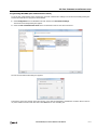
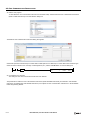
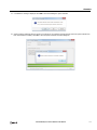
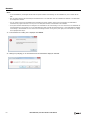
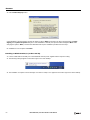
Start WindLDR ............................................................................................................................................ 4-1
PLC Selection.............................................................................................................................................. 4-2
Create Program .......................................................................................................................................... 4-3
Convert Program........................................................................................................................................4-11
Save Project ..............................................................................................................................................4-11
Simulate Operation ....................................................................................................................................4-12
Download Program ....................................................................................................................................4-14
Monitor Operation......................................................................................................................................4-15
Exit WindLDR ............................................................................................................................................4-16
Start/Stop Operation ..................................................................................................................................4-17
Special Functions
Function Area Settings ................................................................................................................................ 5-2
Stop Input and Reset Input ......................................................................................................................... 5-4
Run/Stop Selection at Memory Backup Error ................................................................................................. 5-5
Run/Stop Selection at Power Up................................................................................................................... 5-6
Keep Designation for Internal Relays, Shift Registers, Counters, and Data Registers ........................................ 5-7
Data Register ROM Backup .......................................................................................................................... 5-9
High-Speed Counter ...................................................................................................................................5-13
Catch Input ...............................................................................................................................................5-32
Interrupt Input ..........................................................................................................................................5-34
Frequency Measurement ............................................................................................................................5-36
Input Filter ................................................................................................................................................5-38
FT1A SmartAXIS Pro/Lite User’s Manual FT9Y-B1378
TABLE OF CONTENTS
Analog Input ............................................................................................................................................. 5-39
Timer Interrupt ......................................................................................................................................... 5-41
Forced I/O function ................................................................................................................................... 5-43
Communication Ports................................................................................................................................. 5-46
Memory Cartridge...................................................................................................................................... 5-49
SD Memory Card ....................................................................................................................................... 5-52
Backlight ON Time..................................................................................................................................... 5-57
Monitoring Ladder Program ........................................................................................................................ 5-58
Message Settings ...................................................................................................................................... 5-60
32-bit Data Storage Setting ........................................................................................................................ 5-62
User Program Protection ............................................................................................................................ 5-64
Watchdog Timer Setting ............................................................................................................................ 5-66
Constant Scan Time................................................................................................................................... 5-67
Daylight Savings Time ............................................................................................................................... 5-68
Clock Function........................................................................................................................................... 5-69
Network Settings ....................................................................................................................................... 5-72
Connection Settings................................................................................................................................... 5-73
Remote Host List ....................................................................................................................................... 5-75
CHAPTER 6:
HMI Function
CHAPTER 7:
Device Addresses
CHAPTER 8:
Instructions/Function Blocks Reference
CHAPTER 9:
CHAPTER 10:
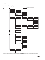
About the Menu Screen................................................................................................................................ 6-2
Basic Operations ......................................................................................................................................... 6-3
Switching to the System Menu ..................................................................................................................... 6-6
Switching run/stop ...................................................................................................................................... 6-7
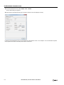
SmartAXIS Environment Settings .................................................................................................................. 6-8
Monitoring the SmartAXIS .......................................................................................................................... 6-15
Checking/Clearing Error Information ........................................................................................................... 6-20
Uploading/Downloading the User Program .................................................................................................. 6-22
Displaying Arbitrary Messages .................................................................................................................... 6-24
Maintaining the SD Memory Card................................................................................................................ 6-25
Entering a Password .................................................................................................................................. 6-27
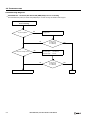
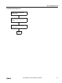
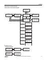
System Menu Hierarchy Diagram ................................................................................................................ 6-28
Device Addresses ........................................................................................................................................ 7-1
Special Internal Relays................................................................................................................................. 7-2
Special Data Registers ................................................................................................................................. 7-8
Ladder Program Instructions List .................................................................................................................. 8-1
Advanced Instruction List ............................................................................................................................. 8-3
Advanced Instruction Applicable SmartAXIS .................................................................................................. 8-6
FB List ........................................................................................................................................................ 8-9
Maintenance Communication
Maintenance Communication via USB Port..................................................................................................... 9-2
Maintenance Communication via Expansion Communication Port .................................................................... 9-3
Maintenance Communication via Ethernet Port .............................................................................................. 9-5
User Communication Instructions
User Communication via Serial Communication............................................................................................ 10-1
User Communication Overview ................................................................................................................... 10-1
User Communication Mode Specifications .................................................................................................... 10-1
RS232C User Communication System Setup ................................................................................................ 10-2
RS485 User Communication System Setup .................................................................................................. 10-3
Programming WindLDR.............................................................................................................................. 10-4
RS232C Line Control Signals..................................................................................................................... 10-11
User Communication via Ethernet Communication ..................................................................................... 10-14
Ethernet User Communication Overview.................................................................................................... 10-14
User Communication Client ...................................................................................................................... 10-16
SMARTAXIS PRO/LITE USER'S MANUAL FT9Y-B1378
II
TABLE OF CONTENTS
User Communication Server......................................................................................................................10-19
Programming WindLDR (User Communication Server) ................................................................................10-20
User Communication Error ........................................................................................................................10-22
ASCII Character Code Table .....................................................................................................................10-23
Sample Program – User Communication TXD .............................................................................................10-24
Sample Program – User Communication RXD .............................................................................................10-26
CHAPTER 11:
CHAPTER 12:
CHAPTER 13:
CHAPTER 14:
APPENDIX
Modbus Communication
Modbus Communication via RS-232C/RS-485 ...............................................................................................11-1
Modbus Master Communication...................................................................................................................11-2
Modbus Slave Communication.....................................................................................................................11-8
Communication Format ............................................................................................................................11-12
Modbus Communication via Ethernet Communication .................................................................................11-18
Modbus TCP Client ...................................................................................................................................11-19
Modbus TCP Server..................................................................................................................................11-24
Remote I/O
Remote I/O Master ....................................................................................................................................12-2
Remote I/O Slave ......................................................................................................................................12-8
Scripts
Script Programming and Management .........................................................................................................13-3
Programming Scripts ................................................................................................................................13-10
Script Programming Examples...................................................................................................................13-16
Important Notes ......................................................................................................................................13-35
About the Priority of the Operator .............................................................................................................13-35
Troubleshooting
Reading Error Data ....................................................................................................................................14-1
Special Data Registers for Error Information ................................................................................................14-3
General Error Codes ...................................................................................................................................14-3
SmartAXIS Operating Status, Output, and ERR LED during Errors..................................................................14-4
Error Causes and Actions............................................................................................................................14-4
User Program Execution Error .....................................................................................................................14-6
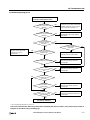
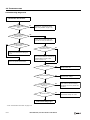
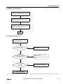
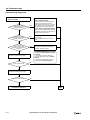
Troubleshooting Diagrams ..........................................................................................................................14-7
System Software......................................................................................................................................... A-1
USB Driver Installation Procedure................................................................................................................. A-5
Cables........................................................................................................................................................ A-8
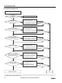
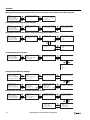
HMI Screen Transition Diagram.................................................................................................................. A-11
Type List .................................................................................................................................................. A-15
Fonts ....................................................................................................................................................... A-17
INDEX
III
SMARTAXIS PRO/LITE USER'S MANUAL FT9Y-B1378
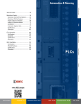
1: GENERAL INFORMATION
Introduction
This chapter describes SmartAXIS functions and system configuration examples. The SmartAXIS is available in three types: the
SmartAXIS Lite, the SmartAXIS Pro, and the SmartAXIS Touch. The SmartAXIS Lite is equipped with the same various control and
communication functions as a PLC. In addition to the functions of the SmartAXIS Lite, the SmartAXIS Pro is equipped with an LCD
and operation buttons on the front of the module. The SmartAXIS Touch is equipped with the HMI functions of an operator
interface and PLC control functions.
This document describes the SmartAXIS Lite and Pro. Unless otherwise specified, SmartAXIS refers to the SmartAXIS Lite and Pro.
For the SmartAXIS Touch, refer to the SmartAXIS Touch User's Manual.
About the SmartAXIS
The SmartAXIS is a small-size programmable controller that is fully equipped with powerful functions and various communication
functions.
You can select the type of SmartAXIS best-suited for your applications, in such ways as the inclusion of the display function, the
type of power supply, and the number of inputs and outputs.
The SmartAXIS Lite is equipped with basic functions. The SmartAXIS Pro adds to the functionality of the SmartAXIS Lite and is
equipped with an LCD and operation buttons on the module, enabling independent monitor and operation functions.
The SmartAXIS supports 100 to 240V AC and 24V DC power supplies. SmartAXIS with Ethernet port (24-, 40-, 48-I/O types) can
expand the number of inputs and outputs for a maximum of 90 inputs and a maximum of 54 outputs using the remote I/O
function.
User programs can be created using WindLDR, the PLC programming software.
The SmartAXIS supports ladder programs and function block programs. Ladder programs for FT1A are compatible with other IDEC
PLCs including MicroSmart and MicroSmart Pentra, so you can make use of existing software assets.
Type Numbers
The notation for SmartAXIS part numbers is as follows.
FT1A - H 12 R A
Power supply type
A: DC power type (24V DC)
C: AC power type (100 to 240V AC)
Output type
R: Relay output
RK: Relay output/transistor sink output
RS: Relay output/transistor source output
K: Transistor sink output
S: Transistor source output
Inputs/outputs
12: 12 I/O points
24: 24 I/O points
40: 40 I/O points
48: 48 I/O points
H: With LCD and operation buttons
B: Without LCD and operation buttons
FT1A: Type number
Note: For the input specifications, see "Input Specifications (AC Power Type)" on page 2-8 to "Input Specifications (DC Power Type)" on page 2-10.
SMARTAXIS PRO/LITE USER'S MANUAL FT9Y-B1378
1-1
1: GENERAL INFORMATION
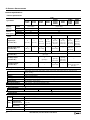
Type List
Type Number
Power Supply
FT1A-H12RA
24V DC
FT1A-H12RC
100 to 240V AC
FT1A-B12RA
24V DC
FT1A-B12RC
100 to 240V AC
FT1A-H24RA
24V DC
FT1A-H24RC
100 to 240V AC
FT1A-B24RA
24V DC
FT1A-B24RC
100 to 240V AC
FT1A-H40RKA
FT1A-H40RSA
FT1A-H40RC
FT1A-B40RKA
FT1A-B40RSA
FT1A-B40RC
FT1A-H48KA
FT1A-H48SA
FT1A-H48KC
FT1A-H48SC
FT1A-B48KA
FT1A-B48SA
FT1A-B48KC
FT1A-B48SC
Inputs and
Outputs
(In/Out)
LCD,
Operation
Buttons
Expansion
Communication
Port
Ethernet
Port
—
—
SD Memory
Card slot
Yes
12 (8/4)
—
—
Yes
Yes
1 port
24 (16/8)
—
24V DC
100 to 240V AC
USB Port
Yes
40 (24/16)
24V DC
Yes
—
Yes
100 to 240V AC
24V DC
Yes
Yes
2 ports
100 to 240V AC
48 (30/18)
24V DC
—
100 to 240V AC
Options
1-2
RS232C Communication Cartridge
RS485 Communication Cartridge
RS485 Communication Cartridge
FT1A-PC1 (Mini-DIN type)
FT1A-PC2 (Mini-DIN type)
FT1A-PC3 (Terminal block type)
Memory Cartridge
SD Memory Card (2GB)
FT1A-PM1
HG9Z-XMS2
USB Maintenance Cable
Panel Mount USB Extension Cable
HG9Z-XCM42
HG9Z-XCE21
SMARTAXIS PRO/LITE USER'S MANUAL FT9Y-B1378
Yes
1: GENERAL INFORMATION
Features
This section describes the features of the SmartAXIS.
The SmartAXIS is high-performance programmable controller in a compact package and is equipped with high speed counters that
can be used for positioning control. The SmartAXIS enables you to build optimum systems to automate factories or control
production lines.
Powerful HMI Functions
The SmartAXIS Pro is equipped with an LCD on the front of the module, enabling you to monitor the device values and the ladder
program. Customized messages can be programmed to display current time, bar charts, scrolling messages, or simple text on the
LCD. The operation buttons on the module are used for operations with LCD such as checking and modifying device values.
Powerful Communication Functions
The SmartAXIS supports various communications such as maintenance communication, user communication, Modbus
communication, and remote I/O.
The SmartAXIS is equipped with RS232C (optional), RS485 (optional), an Ethernet port, and a USB port, and can be connected to
various devices such as computers, operator interfaces, and printers.
RS232C Communication Cartridge
RS485 Communication Cartridge
RS485 Communication Cartridge
FT1A-PC1 (Mini-DIN type)
FT1A-PC2 (Mini-DIN type)
FT1A-PC3 (Terminal block type)
Memory Cartridge
A user program of SmartAXIS can be stored in a memory cartridge (FT1A-PM1). When a memory cartridge is inserted into a
SmartAXIS, the user program in the memory cartridge is executed instead of the user program in the SmartAXIS. You can also
download the user program in a memory cartridge to the SmartAXIS.
Memory Cartridge
FT1A-PM1
SD Memory Card
The 40- and 48-I/O types are equipped with an SD memory card slot. The log data of device values can be saved to an optional SD
memory card (HG9Z-XMS2) or a commercially available SD memory card (32 GB maximum).
32-bit and Floating Point Data Types
Some advanced instructions can select 32-bit data types from D (double word), L (long), and F (float) in addition to W (word) and
I (integer).
Safety and High-Quality Compliant with International Standards
The SmartAXIS is compliant with international standards and can be used all over the world while maintaining safety and high
quality.
Supports 9 Languages
The SmartAXIS LCD supports the display of the following nine languages:
Setting Name
European
Character Set
Supported Languages
ISO 8859-1 (Latin-1)
English, German, Italian, Spanish, Dutch (Note), French (Note)
Japanese
Shift-JIS
Japanese (level 1)
Chinese
GB2312
Chinese (simplified)
ANSI 1251
Russian
Cyrillic
Note: Some of the characters cannot be input.
SMARTAXIS PRO/LITE USER'S MANUAL FT9Y-B1378
1-3
1: GENERAL INFORMATION
Special Functions
This section describes the functions of the SmartAXIS.
I/O Related Functions
Catch Input
The catch input receives short input pulses from sensors without regard to the scan time. A maximum of 6 catch inputs can be
used.
Input Filter
The input filter can be adjusted, according to the width of input signals, to reject input noises. Selectable input filter values to pass
input signals are 0ms, and 3 through 15ms in 1ms increments. The input filter rejects inputs shorter than the selected input filter
value minus 2ms. This function is useful for eliminating input noises and chatter in limit switches.
Interrupt Input
The interrupt input can be used to call an interrupt program to respond to an external input that requires a response faster than
the scan time. A maximum of six interrupt inputs can be used. This can only be used when ladder program is selected as the
programming language.
Stop and Reset Inputs
Stop input is a function to stop SmartAXIS operation. Reset input is a function to stop SmartAXIS operation and clear device
values. Any input terminal on the SmartAXIS can be designated as a stop or reset input to control the SmartAXIS operation.
Remote I/O
When the number of SmartAXIS inputs and outputs is insufficient, the number of inputs and outputs can be expanded to a
maximum of 192 points by connecting additional SmartAXIS as remote I/O slaves over Ethernet. With the remote I/O function, the
analog inputs on the SmartAXIS that are connected as remote I/O slaves can also be used.
Analog Input
Analog input of 0 to 10V DC can be converted to a digital value of 0 to 1000. A maximum of eight inputs can be used as analog
inputs (not including remote I/O slaves analog inputs).
Forced I/O
The inputs and outputs of the SmartAXIS can be forced on or off. This function can be used to check the I/O wiring or the user
program operation.
Pulse I/O Functions
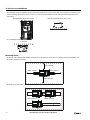
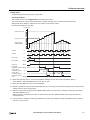
High-speed Counter
This function counts high-speed pulse inputs that cannot be measured in normal user program processing.
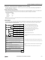
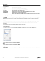
Use this function for applications such as positioning control with a rotary encoder or motor control. The SmartAXIS can use singlephase high-speed counters and two-phase high-speed counters. A maximum of six single-phase high-speed counters and a
maximum of two two-phase high-speed counters can be used simultaneously.
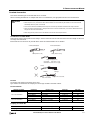
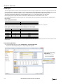
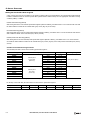
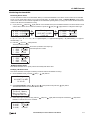
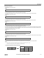
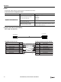
Example: Controlling a motor by counting two-phase pulse input with a high-speed counter
Pulse motor
Rotary
encoder
High-speed pulse input
Two-phase pulses
SmartAXIS
1-4
SMARTAXIS PRO/LITE USER'S MANUAL FT9Y-B1378
1: GENERAL INFORMATION
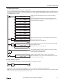
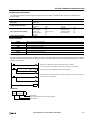
Positioning Control
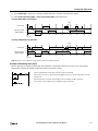
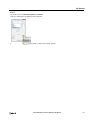
The SmartAXIS can perform positioning control with pulse outputs. The SmartAXIS features the PULS instructions that can
generate pulse outputs with configured frequency at the fixed pulse width ratio, pulse-width modulation (PWM) instructions that
can generate pulse outputs with configured pulse width ratio at a fixed frequency, RAMP instructions for trapezoidal control, ZRN
instructions for zero return operation, and ARAMP instructions that can generate pulse outputs according to a table in which the
changes of the frequency are configured.
Example: Pulse output by the RAMP instruction
Steady pulse frequency
Initial pulse frequency
Frequency Measurement
This function measures the frequency of pulses input to an input terminal. The frequencies of a maximum of six inputs can be
measured.
Convenient Functions
Calendar/Clock
The SmartAXIS features a real-time clock on-board. Using the calendar and clock function, the SmartAXIS can operate according
to the current date and time. These functions can be used to control a time schedule for lighting or air conditioning equipments.
User Program Read/Write Protection
The user program in the SmartAXIS can be protected against reading and/or writing by including a password in the user program.
This function is effective for security of user programs.
“Keep” or “Clear” Designation of SmartAXIS Data
Internal relays, shift register bits, counter current values, and data register values can be designated to be kept or cleared when
the SmartAXIS is powered down. All or a specified range of these devices can be designated as keep or clear types.
RUN/STOP Selection at Startup when “Keep” Data is Lost
When the backup battery is dead, all data to be kept are lost. The user can select whether the SmartAXIS starts to run or not to
prevent undesirable operation at the startup.
Log Data
Device values of the SmartAXIS can be saved as CSV files on the SD memory card. The DLOG instruction saves device values to
the SD memory card. The TRACE instruction accumulates device values at each scan and saves them to the SD memory card at
the desired timing.
Constant Scan Time
The variations in scan time that occur when the user program is running can be made constant.
Timer Interrupt
The timer interrupt can be used to call an interrupt program at a predetermined interval of time without being affected by the scan
time. This can only be used when ladder program is selected as the programming language.
SMARTAXIS PRO/LITE USER'S MANUAL FT9Y-B1378
1-5
1: GENERAL INFORMATION
Communication Functions
The SmartAXIS features a variety of communication functions.
RS232C and RS485 communication of SmartAXIS is possible by installing the RS232C or RS485 communication cartridges into the
expansion communication ports on the SmartAXIS module. The 24-, 40-, and 48-I/O types also feature an Ethernet port as
standard, enabling communication over Ethernet.
Communication Functions
Maintenance Communication
(Chapter 9)
Maintenance communication enables you to check the operating status and I/O status of the SmartAXIS,
monitor and change device values, and download and upload user programs using a computer or
operator interface.
User Communication
(Chapter 10)
The SmartAXIS can communicate with external devices equipped with RS232C, RS485, or Ethernet ports
using user communication. This can only be used when ladder program is selected as the programming
language.
Modbus Communication
(Chapter 11)
The SmartAXIS can send and receive data with Modbus compliant devices on RS232C, RS485, or the
Ethernet port.
For details on the communications functions, refer to the chapter for each function.
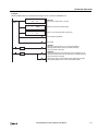
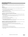
Communication Ports
USB Port
Maintenance communication can be performed by connecting the SmartAXIS and a computer with USB.
Ethernet Port
The SmartAXIS can communicate with Ethernet devices such as computers and operator interfaces.
Maintenance communication, user communication, Modbus communication, and remote I/O are possible.
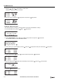
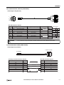
Expansion Communication
Ports
Maintenance communication, user communication, and Modbus RTU communication are possible.
Expansion Communication Ports
The SmartAXIS can perform RS232C/RS485 communication by installing RS232C or RS485 communication cartridges to the
expansion communication ports on the SmartAXIS. The expansion communication ports are available on 24-, 40-, and 48-I/O
types.
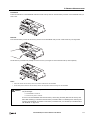
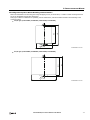
Example: 40-I/O type
Expansion communication ports
1-6
SMARTAXIS PRO/LITE USER'S MANUAL FT9Y-B1378
1: GENERAL INFORMATION
Maintenance Communication
The maintenance communication of the SmartAXIS enables you to check the operating status and I/O status of the SmartAXIS,
monitor and change device values, and download and upload user programs with the PLC programming software WindLDR
installed on a computer. For details on maintenance communication, see "Maintenance Communication" on page 9-1.
Supported ports: USB port, Ethernet port, and expansion communication ports
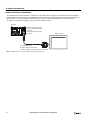
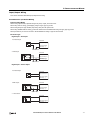
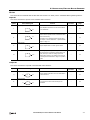
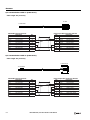
1:1 Maintenance Communication System
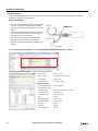
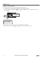
This example shows a 1:1 maintenance communication system in which a SmartAXIS and a computer are connected with USB.
The USB maintenance cable (HG9Z-XCM42) is used.
SmartAXIS
Windows computer
USB maintenance cable
USB port
Mini-B plug
Type A plug
USB port
(USB 2.0 Mini-B connector)
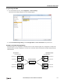
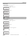
1:N Maintenance Communication System
This example shows a 1:N maintenance communication system in which three SmartAXIS and a computer are connected over
Ethernet. The Ethernet cables are connected to the Ethernet ports of three SmartAXIS, and those SmartAXIS are connected to the
computer via an Ethernet hub.
Windows computer
Ethernet hub
Ethernet port
SmartAXIS
Ethernet port
Ethernet port
SmartAXIS
SmartAXIS
SMARTAXIS PRO/LITE USER'S MANUAL FT9Y-B1378
1-7
1: GENERAL INFORMATION
User Communication
The user communication of the SmartAXIS enables you to control external devices such as computers, printers, and barcode
readers. For details on user communication, see "User Communication Instructions" on page 10-1.
Supported ports: Ethernet port and expansion communication ports
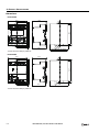
User Communication on RS232C
This example shows a system in which a SmartAXIS receives the data read by a barcode reader. The RS232C communication
cartridge (FT1A-PC1) is installed in a SmartAXIS expansion communication port, and then the barcode reader is connected to the
RS232C port.
SmartAXIS
Expansion communication
port
RS232C communication
cartridge (FT1A-PC1)
Barcode reader
Modbus Communication
The SmartAXIS is compliant with Modbus protocol and can be used as either a Modbus communication master or slave. When
used as a Modbus master, the SmartAXIS can monitor and modify the data of Modbus compliant devices, such as inverters and
temperature controllers, using Modbus communication.
For details on Modbus communication, see "Modbus Communication" on page 11-1.
Supported ports: Ethernet port and expansion communication ports
Modbus Communication on RS485
This example shows a system in which a SmartAXIS is communicating with a temperature controller and an inverter that support
Modbus RTU. The RS485 communication cartridge (FT1A-PC3) is installed in an expansion communication port on the SmartAXIS.
SmartAXIS
Temperature controller
Expansion
communication
port
RS485 communication
cartridge
(FT1A-PC3)
INVERTER
Inverter
RUN
RVS
ALM
COM
Shielded twisted-pair cable
1-8
SMARTAXIS PRO/LITE USER'S MANUAL FT9Y-B1378
1: GENERAL INFORMATION
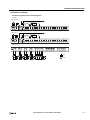
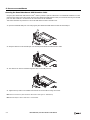
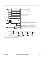
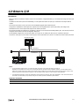
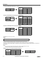
Remote I/O
The remote I/O of the SmartAXIS enables you to expand the number of inputs and outputs by connecting separate SmartAXIS
modules over Ethernet as remote I/O slaves when you run out of inputs and outputs. The SmartAXIS remote I/O master can use
the digital inputs and outputs and analog inputs on the remote I/O slaves.
This function can be used on the Ethernet port only. Remote I/O cannot be used with the expansion communication ports (RS232C
and RS485).
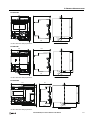
Remote I/O System Example
A SmartAXIS is connected to an Ethernet network as a remote I/O master. Two other SmartAXIS are used as remote I/O slaves.
Up to a maximum of 3 SmartAXIS can be connected to a remote I/O master as remote I/O slaves.
Ethernet hub
Master
Slave
Slave
48-I/O type
48-I/O type
48-I/O type
48-I/O type (master) + 48-I/O type (slave)
+ 48-I/O type (slave)
(30 inputs, 18 outputs)+ (30 inputs, 18 outputs) + (30 inputs, 18 outputs)
= 90 inputs, 54 outputs
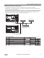
Ethernet Communication
The SmartAXIS can be connected to the Ethernet network via Ethernet port and communicate with network devices over Ethernet.
The SmartAXIS has three TCP/IP connections that can be used for Ethernet communication functions. Each of these connections
can simultaneously be used for a different communication protocol. Each connection can be configured for maintenance
communication, user communication, Modbus TCP, or remote I/O master.
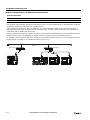
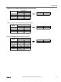
Ethernet Communication Example
This example shows a system in which a SmartAXIS communicates with another SmartAXIS, an operator interface, and a
computer simultaneously over Ethernet. Among the three connections the SmartAXIS has, Connection 1 is configured as
maintenance communication for the computer to communicate with the SmartAXIS. Connection 2 is configured as Modbus TCP
server for the operator interface to communicate with the SmartAXIS. Connection 3 is configured as the remote I/O master to
communicate with another SmartAXIS.
Ethernet
Ethernet Hub
SmartAXIS
Ethernet port
Ethernet Hub
SmartAXIS
Operator interface
Windows computer
Notes:
When accessing the SmartAXIS over the Internet, adequate safety measures are required. Be sure to consult your network administrator or
Internet service provider. IDEC bears no responsibility for damages or problems caused due to security in Ethernet communication.
Restrict the access to SmartAXIS with IP addresses and ports by using appropriate measures such as the firewall.
SMARTAXIS PRO/LITE USER'S MANUAL FT9Y-B1378
1-9
1: GENERAL INFORMATION
Operator Interface Connectivity
The SmartAXIS can perform maintenance communication with IDEC operator interfaces using the Ethernet port and expansion
communication ports. Device values of the SmartAXIS can be monitored and modified with the connected operator interface. An
Ethernet cable or an O/I communication cable (see Note) is used to connect the SmartAXIS and the operator interface.
For details on communication settings, refer to the operator interface manuals.
SmartAXIS
Expansion communication ports
RS232C communication cartridge
(FT1A-PC1)
RS485 communication cartridge
(FT1A-PC3)
Operator interface
O/I communication cable
For RS232C: FC4A-KC1C/FC4A-KC2C
For RS485: FC2A-KP1C (open end at operator interface side)
Note: For details on O/I communication cables, see "Cables" on page A-8.
1-10
SMARTAXIS PRO/LITE USER'S MANUAL FT9Y-B1378
2: PRODUCT SPECIFICATIONS
Introduction
This chapter describes part names and specifications of the SmartAXIS.
SmartAXIS is available in 12-, 24-, 40-, and 48-I/O types. The 12-I/O type has 8 input and 4 output terminals, the 24-I/O type has
16 input and 8 output terminals, the 40-I/O type has 24 input and 16 output terminals, and the 48-I/O type has 30 input and 18
output terminals. The 24-, 40-, and 48-I/O types have 1 or 2 port connectors to install an optional RS232C or RS485
communication cartridge for maintenance communication, user communication, or Modbus RTU communication. The 24-, 40-, and
48-I/O types have built-in Ethernet port for maintenance communication, user communication, Modbus TCP, or Remote I/O. The
40- and 48-I/O types have SD memory card slot to install an SD memory card for logging the device data. Every type of SmartAXIS
has a cartridge connector to install an optional memory cartridge.
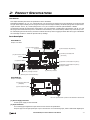
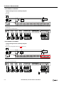
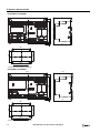
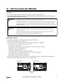
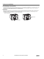
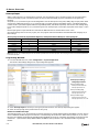
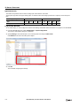
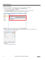
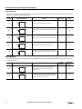
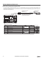
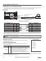
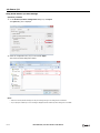
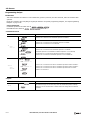
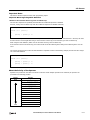
Parts Description
SmartAXIS Pro
Example: FT1A-H48KA
(1) Power Supply Terminals
(2) Input Terminals
(3) Ethernet Port
(4) Ethernet Status LED [Ethernet]
(5) SD Memory Card Status LED
[SD Access]
(17) Sensor Power Terminals
(14) LCD
(13) Operation Buttons
(7) Expansion Communication Port (Port 3)
(6) Expansion Communication Port (Port 2)
(8) Output Terminals
(10) USB Port Cover
(9) SD Memory Card Slot
(11) Memory Cartridge Connector
(12) USB Port (USB 2.0 Mini-B Connector)
SmartAXIS Lite
Example: FT1A-B48KA
(15) Power/Run Status LED
[PWR/RUN]
(16) Error Status LED [ERR]
The text in square brackets is printed on the SmartAXIS to describe LED.
(1) Power Supply Terminals
Connect power supply to these terminals.
(2) Input Terminals
For connecting input signals from input devices such as sensors and pushbuttons.
DC power type can use high-speed input of up to 100 kHz and 0 to 10V DC analog input, which is shared with digital input.
SMARTAXIS PRO/LITE USER'S MANUAL FT9Y-B1378
2-1
2: PRODUCT SPECIFICATIONS
(3) Ethernet Port
This port is used for Ethernet connection. An Ethernet cable can be connected to enable the SmartAXIS to communicate with
network devices, such as computers or PLCs. Not available on the 12-I/O type.
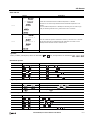
(4) Ethernet Status LED [Ethernet]
Turns on or blinks when an Ethernet cable is connected to the SmartAXIS and the SmartAXIS communicates with network
devices. Not available on the 12-I/O type.
Ethernet Status LED
Status
OFF
Ethernet cable is not connected.
ON
Ethernet cable is connected and communication is possible.
Flashing
Ethernet cable is connected and data is being sent or received.
(5) SD Memory Card Status LED [SD Access]
Turns on or blinks when the SD memory card is being accessed. Not available on the 12- or 24-I/O type.
SD Memory Card Status LED
Status
When the SD memory card is not inserted
OFF
When an unsupported or unformatted SD memory card was inserted
When access to the SD memory card was stopped by SD memory card access stop flag (M8076)
When the SmartAXIS power is off
ON
The standby state where the SD memory card can be written or read
When the SmartAXIS is recognizing the SD memory card
Slow Flash (1-sec interval)
When the SmartAXIS is stopping access due to SD memory card access stop flag (M8076)
Quick Flash (100ms interval)
Reading or writing to the SD memory card
turning on (slow flashing, then off)
(6) Expansion Communication Port (Port2)
(7) Expansion Communication Port (Port3)
This port is used to install a communication cartridge for communication with external devices. The 24-I/O type has one
expansion communication port while the 40- and 48-I/O types have two. Not available on the 12-I/O type.
(8) Output Terminals
For connecting output signals to output devices such as electromechanical relays and solenoid valves. Relay output (10A and
2A types) and transistor output (sink/source) are available.
(9) SD Memory Card Slot
Insert SD memory card to this slot. Not available on the 12- or 24-I/O type.
(10) USB Port Cover
Protects the USB port and the memory cartridge. If the panel mount USB extension cable is to be connected permanently, it
can be secured to the USB port cover using a cable tie.
(11) Memory Cartridge Connector
For connecting an optional memory cartridge.
(12) USB Port
A Mini-B type USB 2.0 connector. A USB maintenance cable or panel mount USB extension cable can be attached and
connected to a PC to download and upload user programs using WindLDR.
(13) Operation Buttons
For operating the menus displayed on the LCD to access functions. There are six operation buttons: [
[
], [OK], and [ESC].
Not available on the SmartAXIS Lite.
(14) LCD
Displays operation menus, status, and setting of the SmartAXIS. Not available on the SmartAXIS Lite.
2-2
SMARTAXIS PRO/LITE USER'S MANUAL FT9Y-B1378
], [
], [
],
2: PRODUCT SPECIFICATIONS
(15) Power/Run Status LED [PWR/RUN]
A green LED that turns on or flashes to indicate the power supply and operation status.
Power/Run Status LED
Status
OFF
Power is not supplied.
ON
Power is supplied and the user program is being executed.
Slow Flash (1-sec interval)
Power is supplied and the user program is stopped.
Not available on the SmartAXIS Pro.
(16) Error Status LED [ERR]
A red LED that turns on if an error occurs.
Error Status LED
OFF
Status
Normal operation
ON
An error has occurred.
Slow Flash (1-sec interval)
The SmartAXIS is running and the forced I/O function is enabled.
Quick Flash (100 ms interval)
The user program is stopped and the forced I/O function is enabled.
Not available on the SmartAXIS Pro.
(17) Sensor Power Terminals
For supplying power to sensors (24V DC). Not available on the DC power type.
SMARTAXIS PRO/LITE USER'S MANUAL FT9Y-B1378
2-3
2: PRODUCT SPECIFICATIONS
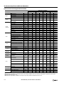
General Specifications
AC Power Type
FT1AType Number
H12RC, B12RC
H24RC, B24RC
H40RC, B40RC
H48KC, H48SC
B48KC, B48SC
Normal Operating Conditions
Operating Temperature
0 to +55°C (operating ambient temperature) (Note 2)
Storage Temperature
–25 to +70°C (no freezing)
Relative Humidity
10 to 95% (non-condensing, operating and storage humidity)
Pollution Degree
2 (IEC60664-1)
Degree of Protection
IP20 (IEC60529)
Corrosion Immunity
Atmosphere free from corrosive gases
Operation: 0 to 2,000m (0 to 6,565 feet)
Altitude
Transport: 0 to 3,000m (0 to 9,840 feet)
Installation Location
Inside cabinet (Note 1)
Device Class
Open equipment
Overvoltage Category
II
Vibration Resistance
When mounted on a DIN rail or panel surface:
5 to 8.4Hz amplitude 3.5mm, 8.4 to 150Hz acceleration 9.8m/s2 (1G)
2 hours per axis on each of three mutually perpendicular axes
Shock Resistance
147 m/s2 (15G), 11ms duration, 3 shocks per axis on three mutually perpendicular axes
Power Supply (Note 3)
Rated Power Voltage
100 to 240V AC
Allowable Voltage Range
85 to 264V AC
Rated Power Frequency
50/60Hz (47 to 63Hz)
Maximum Power Consumption
18VA
Allowable Momentary Power Interruption
10ms maximum (at the rated power voltage)
41VA
48VA
43VA
Between power and PE terminals: 1,500V AC, 1 minute
Between input and PE terminals: 1,500V AC, 1 minute
Between transistor output and PE terminals: 1,500V AC, 1 minute
Between relay output and PE terminals: 2,300V AC, 1 minute
Dielectric Strength Voltage
Between power and input terminals: 1,500V AC, 1 minute
Between power and transistor output terminals: 1,500V AC, 1 minute
Between power and relay output terminals: 2,300V AC, 1 minute
Between input and transistor output terminals: 1,500V AC, 1 minute
Between input and relay output terminals: 2,300V AC, 1 minute
EMC Immunity
IEC/EN 61131-2:2007 compliant
Inrush Current
35A maximum (Cold start with Ta = 25°C, 200V AC)
Ground
D-type ground (Class 3 ground)
Grounding Wire
UL1007 AWG16
Power Supply Wire
UL1015 AWG22, UL1007 AWG18
Effect of Improper Power Supply
Connection
Weight
Reverse polarity: Normal operation
Improper voltage or frequency: Permanent damage may be caused
Improper lead connection: Permanent damage may be caused
Approx. 230g
Approx. 400g
Approx. 580g
Approx. 540g
Note 1: Use in environments that satisfy product specifications.
Note 2: UL, c-UL Listed at 0 to +50°C (FT1A Version V110).
Note 3: Supports input/output overvoltage protection. When overvoltage protection occurred, the power supply output is shut off. In this situation,
shut off the AC input, wait for one minute or longer, and then turn on the AC input again.
2-4
SMARTAXIS PRO/LITE USER'S MANUAL FT9Y-B1378
2: PRODUCT SPECIFICATIONS
DC Power Type
FT1AType Number
H12RA, B12RA
H24RA, B24RA
H40RKA, H40RSA
B40RKA, B40RSA
H48KA, H48SA
B48KA, B48SA
Normal Operating Conditions
Operating Temperature
0 to +55°C (operating ambient temperature) (Note 2)
Storage Temperature
–25 to +70°C (no freezing)
Relative Humidity
10 to 95% (non-condensing, operating and storage humidity)
Pollution Degree
2 (IEC60664-1)
Degree of Protection
IP20 (IEC60529)
Corrosion Immunity
Atmosphere free from corrosive gases
Operation: 0 to 2,000m (0 to 6,565 feet)
Altitude
Transport: 0 to 3,000m (0 to 9,840 feet)
Installation Location
Inside cabinet (Note 1)
Device Class
Open equipment
Overvoltage Category
II
Vibration Resistance
When mounted on a DIN rail or panel surface:
5 to 8.4Hz amplitude 3.5 mm, 8.4 to 150Hz acceleration 9.8m/s2 (1G)
2 hours per axis on each of three mutually perpendicular axes
Shock Resistance
147m/s2 (15G), 11 ms duration, 3 shocks per axis on three mutually perpendicular axes
Power Supply
Rated Power Voltage
24V DC
Allowable Voltage Range
20.4 to 28.8V DC (Including ripple voltage)
Maximum Power Consumption
4.3W
Allowable Momentary Power Interruption
10ms maximum (Rated voltage, PS2)
4.8W
7.9W
6.0W
Between power/input and FE terminals: 500V AC, 1 minute
Between transistor output and FE terminals: 500V AC, 1 minute
Dielectric Strength Voltage
Between relay output and FE terminals: 2,300V AC, 1 minute
Between power/input and transistor output terminals: 500V AC, 1 minute
Between power/input and relay output terminals: 2,300V AC, 1 minute
EMC Immunity
IEC/EN 61131-2:2007 compliant
Inrush Current
30A maximum
Ground
D-type ground (Class 3 ground)
Grounding Wire
UL1007 AWG16
Power Supply Wire
UL1015 AWG22, UL1007 AWG18
Effect of Improper Power Supply
Connection
Weight
Reverse polarity: No operation, no damage
Improper voltage or frequency: Permanent damage may be caused
Improper lead connection: Permanent damage may be caused
Approx. 190g
Approx. 310g
Approx. 420g
Approx. 380g
Note 1: Use in environments that satisfy product specifications.
Note 2: UL, c-UL Listed at 0 to +50°C (FT1A Version V110).
SMARTAXIS PRO/LITE USER'S MANUAL FT9Y-B1378
2-5
2: PRODUCT SPECIFICATIONS
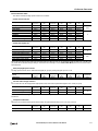
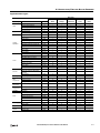
Function Specifications
Function Specifications
FT1AType Number
H12RA
B12RA
H12RC
B12RC
H24RA
B24RA
H40RKA
H40RSA
B40RKA
B40RSA
H24RC
B24RC
H40RC
B40RC
Program
Capacity
(Note 1)
Ladder
12,000 bytes
(3,000 steps)
47,400 bytes
(11,850 steps)
FBD
10,000 bytes
38,000 bytes
Number of
Function
Blocks (Note 2)
Block (B)
200
1,000
Timer (T)
100
200
Counter (C)
100
200
Input
Points
8
Digital Input
(Terminal No.)
Shared Analog Input
(Terminal No.)
16
6
(I0 to I5)
8
(I0 to I7)
12
(I0 to I7,
I10 to I13)
2
(I6, I7)
—
4
(I14 to I17)
Output Points
4
2A Relay Output
(Terminal No.)
Transistor Output
(Terminal No.)
User Program Storage
24
H48KC
H48SC
B48KC
B48SC
30
16
(I0 to I7,
I10 to I17)
18
(I0 to I7,
I10 to I17,
I20, I21)
24
(I0 to I7,
I10 to I17,
I20 to I27)
22
(I0 to I7,
I10 to I17,
I20 to I25)
30
(I0 to I7,
I10 to I17,
I20 to I27,
I30 to I35)
—
6
(I22 to I27)
—
8
(I26, I27,
I30 to I35)
—
8
16
18
4
(Q0 to Q3)
10A Relay Output
(Terminal No.)
H48KA
H48SA
B48KA
B48SA
—
—
4
(Q4 to Q7)
8
(Q4 to Q7,
Q10 to Q13)
12
(Q4 to Q7,
Q10 to Q13,
Q14 to Q17)
—
—
—
4
(Q14 to Q17)
—
18
(Q0 to Q7, Q10 to Q17,
Q20, Q21)
Flash ROM (10,000 rewriting life)
Backup Function
RAM
Backup data: Internal relay, shift register, counter current value, data register (Note 3), clock data (year,
month, and day)
Backup Duration
Approx. 30 days (typical) at 25°C after backup battery fully charged
Battery
Lithium secondary battery
Charging Time
Approx. 15 hours for charging from 0% to 90% of full charge
Battery Life
5 years in cycles of 9-hour charging and 15-hour discharging
Replaceability
Not possible to replace battery
Clock Function (Note 4)
Clock accuracy: ±30 sec/month (typical) at 25°C
Control System
Stored program system
Instruction Words (Ladder)
Basic Instructions
42
Advanced Instructions
99
107
DC type: 125, AC type: 111
Function Block (FBD)
Function Blocks
45
Processing Time
Ladder
FBD
Basic Instruction
0.95 ms (1000 steps)
END Processing
640 μs
Logical
Operation FB
Execution Time
1.3 ms
(100 FBs)
Scan End
Processing
1 ms
Internal Relay
1024
Shift Register
128
2-6
SMARTAXIS PRO/LITE USER'S MANUAL FT9Y-B1378
2: PRODUCT SPECIFICATIONS
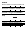
FT1AType Number
H12RA
B12RA
H12RC
B12RC
H24RA
B24RA
H24RC
B24RC
H40RKA
H40RSA
B40RKA
B40RSA
Data Register
12-I/O type: 400
24-I/O type, 40-I/O type, 48-I/O type: 2,000
Counter (adding, reversible)
100
200
Timer (1-sec, 100ms,
10ms, 1ms)
100
200
Input Filter
Without filter, 3 to 15ms (selectable in increments of 1ms)
H40RC
B40RC
H48KA
H48SA
B48KA
B48SA
H48KC
H48SC
B48KC
B48SC
—
Total
6 points
—
Catch Input/Interrupt Input
Input Points
Self-diagnostic Function
4
6
Keep data
Power failure
Clock error
Watchdog timer
Timer/counter preset value change error
User program syntax
User program execution
System error
Memory cartridge transfer error
High-speed Counter
Points
Total
4 points
Total
6 points
—
Total
6 points
—
Maximum Counter
Frequency
Single/two-phase
selectable: 100kHz
(2 points)
Single-phase: 100kHz
(2 points)
Counting Range
0 to 4,294,967,295 (32 bits)
Operation Mode
Rotary encoder mode and adding counter mode
Single/two-phase selectable: 100kHz (2 points)
Single-phase: 100kHz (4 points)
Pulse Output (Maximum frequency: 100kHz)
Points
—
2
(Q14, Q15)
—
2
(Q14, Q15)
—
2
(Q16, Q17)
—
2
(Q16, Q17)
6
(I22 to I27)
—
Pulse Output (Maximum frequency: 5kHz)
Points
Analog Voltage Input
Points (Terminal No.)
2 (I6, I7)
Input voltage Range
0 to 10V DC
Digital Resolution
0 to 1000
—
4
(I14 to I17)
—
8 (I26, I27,
I30 to I35)
—
USB
Port
Points
1
USB Standard
USB 2.0
Connector
Mini-B type
Expansion Communication Ports
Points
—
1
—
1
2
Ethernet Port
Points
Memory Cartridge Connectors
Points
1
SD Memory Card Slots
Points
—
1
Note1: 1 step is equivalent to 4 bytes.
Note2: When FBD program is selected as the programming language.
Note3: Among data registers D0 to D1999, only D0 to D999 are backed up.
Note4: Set the calendar/clock using WindLDR to use the clock function.
SMARTAXIS PRO/LITE USER'S MANUAL FT9Y-B1378
2-7
2: PRODUCT SPECIFICATIONS
LCD Specifications (SmartAXIS Pro only)
Description/Specifications
Type
STN monochrome LCD
Resolution
64 x 192 pixels
Number of Characters
24 digits x 8 lines (8 x 8 pixel font)
12 digits x 8 lines (16 x 8 pixel font)
12 digits x 4 lines (16 x 16 pixel font)
Display Content
System menus, messages, operation status monitor
Contrast Adjustment
Not possible
Backlight
Yes (backlight can be turned on and off)
Input Specifications (AC Power Type)
FT1AType Number
H12RC
B12RC
H24RC
B24RC
Input Points
8
Rated Input Voltage
24V DC
16
Input Voltage Range
0 to 28.8V DC
Terminal Arrangement
See "Terminal Arrangement" on page 2-16.
Input External Power
Supply
Voltage Fluctuation
Range/Capacity (Note 1)
—
DC20.4 to 26.4V
250mA
Contacts
Sink/Source
Input Points
(Terminal No./
Common Line Name)
8 points in 1 common line
(I0 to I7/COM)
16 points in 1 common
line
(I0 to I7, I10 to I17/COM)
Rated Input Current
5.3mA
Input Impedance
4.3kΩ
Turn ON Time
40 μs + filter value
Turn OFF Time
150 μs + filter value
H48KC
H48SC
B48KC
B48SC
H40RC
B40RC
24
30
DC20.4 to 26.4V
300mA
DC20.4 to 26.4V
300mA
24 points in 1 common
line
(I0 to I7, I10 to I17, I20
to I27/COM)
30 points in 2 common
lines
(I0 to I7, I10 to I17, I20
to I25/COMA, I26, I27,
I30 to I35/COMB)
Digital Input
Input Type
Between input terminals: Not isolated
Isolation
Internal circuit: Photocoupler isolated
Input Type
Type 1 (IEC61131-2)
Shared Digital/Analog
Inputs
Status
Display
No
Pro
LCD display
Lite
—
External Load for I/O
Interconnection
Not needed
Signal Determination
Method
Static
Cable Length
100m in compliance with electromagnetic immunity
Effect of Improper
Input Connection
No damage. If any input exceeding the rated value is applied, permanent damage may be caused.
Note 1: When an overload state occurs such as a short circuit in the input external power supply, the power supplied to the internal circuit of the
SmartAXIS is stopped. When the overload state is cleared, the output automatically recovers.
2-8
SMARTAXIS PRO/LITE USER'S MANUAL FT9Y-B1378
2: PRODUCT SPECIFICATIONS
Input Internal Circuit
• Sink/Source Input (FT1A-*24/40/48RC)
24V DC
COM
Internal Circuit
Input
4.3KΩ
Input
4.3kΩ
COM
Internal Circuit
• Contact Input (FT1A-*12RC)
0V
Input Operating Range
Input Voltage (V DC)
28.6
ON Area
24
15
Transition Area
5
OFF Area
1.1
3.0
5.3
5.5
Input Current (mA)
SMARTAXIS PRO/LITE USER'S MANUAL FT9Y-B1378
2-9
2: PRODUCT SPECIFICATIONS
Input Specifications (DC Power Type)
FT1AType Number
H12RA
B12RA
H24RA
B24RA
16
H40RKA
B40RKA
Input Points
12
Rated Input Voltage
24V DC
Input Voltage Range
0 to 28.8V DC
Terminal Arrangement
See "Terminal Arrangement" on page 2-16.
H40RSA
B40RSA
24
H48KA
B48KA
H48SA
B48SA
30
Digital Input
Input Type
Sink
Source
Sink
Source
Sink
Input Points
(Terminal No. /Common Line
Name)
6 points in 1
common line
(I0 to I5/
Internal "-"
terminal)
18 points in 1
common line
(I0 to I7, I10
to I17, I20,
I21/
Internal "+"
terminal)
18 points in 1
common line
(I0 to I7, I10
to I17, I20,
I21/
Internal "-"
terminal)
22 points in 1
common line
(I0 to I7, I10
to I17, I20 to
I25/
Internal "+"
terminal)
22 points in 1
common line
(I0 to I7, I10
to I17, I20 to
I25/
Internal "-"
terminal)
Rated Input Current
4.4mA
5.2mA
4.4mA
5.2mA
4.4mA
Input Impedance
5.5kΩ
4.7kΩ
5.5kΩ
4.7kΩ
5.5kΩ
Turn ON Time
2.5 μs + filter
value
I0 to I7: 2.5μs + filter value
Others: 40μs + filter value
Turn OFF Time
5 μs + filter
value
I0 to I7: 5μs + filter value
Others: 150μs + filter value
Function
Input
High-Speed
Counter
(Two-phase)
2 systems
[System 1]
1-A phase: I0, 1-B phase: I1, 1-Z phase: I2 (for clear input)
[System 2]
2-A phase: I3, 2-B phase: I4, 2-Z phase: I5 (for clear input)
High-Speed
Counter
(Single-phase)
4 points
(I0, I2, I3, I5)
6 points (I0, I2, I3, I5, I6, I7)
Interrupt
4 points
(I0, I2, I3, I5)
6 points (I0, I2, I3, I5, I6, I7)
Catch
4 points
(I0, I2, I3, I5)
6 points (I0, I2, I3, I5, I6, I7)
Frequency
Measurement
4 points
(I0, I2, I3, I5)
6 points (I0, I2, I3, I5, I6, I7)
Isolation
2-10
12 points in 1
common line
(I0 to I7, I10
to I13/
Internal "-"
terminal)
Between input terminals: Not isolated
Internal circuit: Not isolated
Input Type
Type 1 (IEC61131-2)
External Load for I/O
Interconnection
Not needed
Signal Determination Method
Static
Cable Length
(in compliance with
electromagnetic immunity)
3m (9.84 ft.)
I0 to I7: 3m (9.84 ft.)
Others: 100m (328.1 ft.)
SMARTAXIS PRO/LITE USER'S MANUAL FT9Y-B1378
2: PRODUCT SPECIFICATIONS
FT1AType Number
H12RA
B12RA
H24RA
B24RA
H40RKA
B40RKA
H40RSA
B40RSA
H48KA
B48KA
H48SA
B48SA
Analog Input
Input Signal Type
Voltage Input
Input Points
(Terminal No. /Common Line
Name)
2 points in 1
common line
(I6, I7/
Internal "-"
terminal)
Input Range
0 to 10.0V DC
Rated Input Current
0.3mA
Input Impedance
78.0kΩ
Digital Resolution
0 to 1000 (10 bits)
Data Type
Binary data: 0 to 1000
Input Value of LSB
10mV
Type of Input
Single-ended input
AD
Conversion
Input Error
General
Characteristics
Status
Display
4 points in 1
common line
(I14 to I17
Internal "-"
terminal)
Sample
Duration Time
2ms maximum
Sample
Repetition
Time
2ms maximum
Total Input
System
Transfer Time
2ms + filtering time + scan time
Maximum
Error at 25°C
±1.5% of full scale
Temperature
Coefficient
±0.25% of full scale/°C
Maximum
Error
±5.0% of full scale
Operating
Mode
Self-scan
Conversion
Method
Successive Approximation
Pro
"Device Monitor" screen (LCD)
Lite
—
6 points in 1 common line
(I22 to I27/Internal "-"
terminal)
Maximum Temporary Deviation
during Electrical Noise Tests
±5.0% of full scale
Recommended Cable for Noise
Immunity
Twisted pair shielded cable
Calibration or Verification to
Maintain Rated Accuracy
Not possible
Maximum Permanent Allowed
Overload (No Damage)
28.8V DC
Overload Status (Outside Input
Range) Detection
Detectable (Stored in special data register D8077)
Between input terminals: Not isolated
Isolation
Used as
Digital Input
8 points in 1 common line
(I26, I27, I30 to I35/Internal "-"
terminal)
Between input and internal circuit: Not isolated
Digital Input
Type
Input
Threshold
Effect of Improper Input
Connection
— (IEC 61131-2 digital input type is not supported)
ON voltage: 15V minimum (ON current: 0.20mA minimum)
OFF voltage: 5V maximum (OFF current: 0.06mA maximum)
No damage. If any input exceeding the rated value is applied, permanent damage may be caused.
SMARTAXIS PRO/LITE USER'S MANUAL FT9Y-B1378
2-11
2: PRODUCT SPECIFICATIONS
Digital Input Internal Circuits
• Source Input
24V DC
Internal Circuit
24V DC
4.3kΩ
Input
1.0kΩ
24V DC
Internal Circuit
• Sink Input
4.7kΩ
47kΩ
Input
10kΩ
0V
0V
Internal Circuit with Shared Digital/Analog Input
Internal Circuit
24V DC
56kΩ
Input
22kΩ
0V
Digital Input Operating Range
• Sink Input
• Source Input
Input Voltage (V DC)
Input Voltage (V DC)
28.8
28.8
ON Area
ON Area
24
24
15
15
Transition Area
Transition Area
5
5
OFF Area
0.9
2.7
5.3
4.4
OFF Area
Input Current (mA)
-1.0
-3.0
• Operating Range of Shared Digital/Analog Input
Input Voltage (V DC)
28.8
ON Area
24
15
Transition Area
5
OFF Area
0.06
2-12
0.2
0.3
0.37
Input Current (mA)
SMARTAXIS PRO/LITE USER'S MANUAL FT9Y-B1378
-5.2
-6.2
Input Current (mA)
2: PRODUCT SPECIFICATIONS
Output Specifications (10A Relay)
FT1AType Number
H12RC
B12RC
H12RA
B12RA
H24RC
B24RC
H24RA
B24RA
No. of Outputs (Terminal No.)
4 (Q0 to Q3)
Terminal Arrangement
See "Terminal Arrangement" on page 2-16.
Output Type
1a contact
Maximum Load Current
(Note)
10A
Minimum Switching Load
10mA/5V DC (reference value)
Initial Contact Resistance
100mΩ maximum (1A, 6V DC)
Electrical Life
100,000 operations minimum (rated load 1,800 operations/hour)
Mechanical Life
20,000,000 operations minimum (no load 18,000 operations/hour)
Rated Load (Note)
250V AC/10A, 30V DC/10A
Dielectric Strength
Between output terminal and internal circuit: 2,300V AC, 1 minute
Between output terminals (COMs): 2,300V AC, 1 minute
Status
Display
Pro
LCD display
Lite
—
H40RC
B40RC
H40RKA
H40RSA
B40RKA
B40RSA
Note: Values for resistive/inductive load.
Output Delay
ON
Command
OFF
ON
Output Relay Status
OFF
OFF delay: 10ms maximum
Chatter: 6ms maximum
ON delay: 6ms maximum
Derating
When using the SmartAXIS at an operating temperature of 45°C or higher, reduce the output current of the 10A relay and power
supply voltage as shown in the figure below.
Normal Installation
Output Current
10A
Operating Temperature
4 5 °C
Operating Temperature
5 5 °C
8A
0
Power Supply Voltage
24V
28.8V
Note: UL, c-UL Listed at 0 to +50°C (FT1A Version V110).
SMARTAXIS PRO/LITE USER'S MANUAL FT9Y-B1378
2-13
2: PRODUCT SPECIFICATIONS
Output Specifications (2A Relay)
FT1AH24RC
B24RC
H24RA
B24RA
Type Number
4
(Q4 to Q7)
No. of Outputs
(Terminal No.)
Output
Points per
Common
Line
12
(Q4 to Q7, Q10 to Q13,
Q14 to Q17)
8
(Q4 to Q7, Q10 to Q13)
4 (Q4 to Q7)
COM4
4 (Q4 to Q7)
4 (Q4 to Q7)
COM5
—
4 (Q10 to Q13)
4 (Q10 to Q13)
COM6
—
4 (Q14 to Q17)
—
Terminal Arrangement
See "Terminal Arrangement" on page 2-16.
Output Type
1a contact
Maximum
Load Current
1 point
2A
1 common line
8A maximum
Minimum Switching Load
0.1 mA/0.1V DC (reference value)
Initial Contact Resistance
1A, 6V DC
Electrical Life
100,000 operations minimum (rated load 1,800 operations/hour)
Mechanical Life
20,000,000 operations minimum (no load 18,000 operations/hour)
Rated Load (Note)
250V AC/2A, 30V DC/2A
Dielectric Strength
Between output terminal and internal circuit: 2,300V AC, 1 minute
Between output terminals (COMs): 2,300V AC, 1 minute
Status
Display
Pro
LCD display
Lite
—
Note: Values for resistive/inductive load.
Output Delay
ON
Command
OFF
ON
Output Relay Status
OFF
OFF delay: 10ms maximum
Chatter: 6ms maximum
ON delay: 6ms maximum
2-14
H40RKA
H40RSA
B40RKA
B40RSA
H40RC
B40RC
SMARTAXIS PRO/LITE USER'S MANUAL FT9Y-B1378
2: PRODUCT SPECIFICATIONS
Output Specifications (Transistor)
FT1AType Number
Output
Model/
No. of
Point
Output Points per
Common Line
H40RKA
B40RKA
H40RSA
B40RSA
H48KC
B48KC
H48KA
B48KA
4 (Q14 to
Q17)
—
18 (Q0 to Q7,
Q10 to Q17,
Q20, Q21)
—
18 (Q0 to Q7,
Q10 to Q17,
Q20, Q21)
—
Source output
—
4 (Q14 to
Q17)
—
18 (Q0 to Q7,
Q10 to Q17,
Q20, Q21)
—
18 (Q0 to Q7,
Q10 to Q17,
Q20, Q21)
COM0
—
8 (Q0 to Q7)
COM1
—
8 (Q10 to Q17)
COM2
—
2 (Q20, Q21)
COM6
4 (Q14 to Q17)
—
24V DC
Operating Load Voltage Range
20.4 to 28.8V DC
Terminal Arrangement
See "Terminal Arrangement" on page 2-16.
1 point
0.3A maximum
1 common line
1A maximum
Voltage Drop (ON Voltage)
1V maximum (voltage between COM and output terminals when output is on)
Inrush Current
1A maximum
Leakage Current
0.1 mA maximum
Clamping Voltage
39V±1V
Maximum Lamp Load
8W
Inductive Load
L/R = 10ms (28.8V DC, 1 Hz)
External Current Draw
Sink output: 100mA maximum, 24V DC (power voltage at the +V terminal)
Source output: 100mA maximum, 24V DC (power voltage at the +COM terminal)
Function Input
Isolation
100kHz output
2 points (Q14, Q15)
5kHz output
2 points (Q16, Q17)
Between output
terminal and
internal circuit
Photocoupler isolated
Between output
terminals
Same common line: Not isolated
Separate common line: Isolated
Turn ON Time
High-speed output terminal (100 kHz pulse output terminal): 5 μs maximum
Normal output terminal (including 5 kHz pulse output terminal): 100 μs maximum
Turn OFF Time
High-speed output terminal (100 kHz pulse output terminal): 5 μs maximum
Normal output terminal (including 5 kHz pulse output terminal): 100 μs maximum
Pro
LCD display
Lite
—
Output Delay
Status Display
H48SA
B48SA
Sink output
Rated Load Voltage
Maximum Load
Current
H48SC
B48SC
Output Internal Circuit
Sink Output
Source Output
V (+)
Internal
Circuit
COM (+)
Internal
Circuit
Output
COM (-)
SMARTAXIS PRO/LITE USER'S MANUAL FT9Y-B1378
Output
V (-)
2-15
2: PRODUCT SPECIFICATIONS
Terminal Arrangement
FT1A-H12RA, FT1A-B12RA
Terminal Arrangement and I/O Wiring Diagrams
Input Side
+
-
Analog voltage
output device
+
2-wire
Sensor
+
-
Output Side
: Fuse
L
L
L
L
L
: Load
FT1A-H12RC, FT1A-B12RC
Terminal Arrangement and Wiring I/O Diagrams
Input Side
Output Side
: Fuse
L
L
L
L
L : Load
2-16
SMARTAXIS PRO/LITE USER'S MANUAL FT9Y-B1378
2: PRODUCT SPECIFICATIONS
FT1A-H24RA, FT1A-B24RA
Terminal Arrangement and I/O Wiring Diagrams
Input Side
+
-
Analog voltage
output device
+
2-wire
Sensor
+
-
Output Side
L
L
L
L
L
L
L
: Fuse
L
L
: Load
FT1A-H24RC, FT1A-B24RC
Terminal Arrangement and I/O Wiring Diagrams
Input Side
● Source Input
-
-
2-wire
Sensor
+ External
Power
+
● Sink Input
+
+
2-wire
Sensor
- External
-
Power
Output Side
L
L
L
L
L
L
L
L
: Fuse
L : Load
SMARTAXIS PRO/LITE USER'S MANUAL FT9Y-B1378
2-17
2: PRODUCT SPECIFICATIONS
FT1A-H40RSA, FT1A-B40RSA
Terminal Arrangement and I/O Wiring Diagrams
Input Side
● Sink Input
Analog voltage
output device
2-wire
Sensor
Output Side
● Source Output (Transistor Output)
FT1A-H40RKA, FT1A-B40RKA
Terminal Arrangement and I/O Wiring Diagrams
Input Side
● Source Input (Analog/Digital Shared Input
is Sink Input)
Analog voltage
output device
2-wire
Sensor
Output Side
● Sink Output (Transistor Output)
: Fuse
2-18
SMARTAXIS PRO/LITE USER'S MANUAL FT9Y-B1378
: Load
2: PRODUCT SPECIFICATIONS
FT1A-H40RC, FT1A-B40RC
Terminal Arrangement and I/O Wiring Diagrams
Input Side
● Source Input
-
-
2-wire
Sensor
+ External
Power
+
● Sink Input
+
+
-
2-wire
Sensor
External
Power
-
Output Side
L
L
L
L
L
L
L
L
: Fuse
L : Load
SMARTAXIS PRO/LITE USER'S MANUAL FT9Y-B1378
2-19
2: PRODUCT SPECIFICATIONS
FT1A-H48SA, FT1A-B48SA
Terminal Arrangement and I/O Wiring Diagrams
Input Side
● Sink Input
+
-
Analog voltage
output device
+
2-wire
Sensor
+
-
Output Side
● Source Output
L
L
L
L
L
L
L
L
L
L
L
L
L
L
L
L
L
L
L : Load
: Fuse
FT1A-H48KA, FT1A-B48KA
Terminal Arrangement and I/O Wiring Diagrams
Input Side
● Source Input (Analog/Digital Shared Input
is Sink Input)
+
-
Analog voltage
output device
2-wire
Sensor
+
+
Output Side
● Sink Output
L
L
L
L
L
L
L
L
L
L
L
L
L
L
L
L
L
L
: Fuse
2-20
SMARTAXIS PRO/LITE USER'S MANUAL FT9Y-B1378
L : Load
2: PRODUCT SPECIFICATIONS
FT1A-B48SC, FT1A-H48SC
Terminal Arrangement and I/O Wiring Diagrams
Input Side
● Source Input
+ External
Power
2-wire
Sensor
+
2-wire
Sensor
+
+
2-wire
Sensor
-
+
2-wire
Sensor
-
+
External
Power
● Sink Input
+
- External
Power
+
-
External
Power
Output Side
● Source Output
L
L
L
L
L
L
L
L
L
L
L
L
L
L
L
L
L
L
: Fuse
SMARTAXIS PRO/LITE USER'S MANUAL FT9Y-B1378
L : Load
2-21
2: PRODUCT SPECIFICATIONS
FT1A-H48KC, FT1A-B48KC
Terminal Arrangement and I/O Wiring Diagrams
Input Side
● Source Input
+ External
Power
2-wire
Sensor
+
2-wire
Sensor
+
+
2-wire
Sensor
-
+
2-wire
Sensor
-
+
External
Power
● Sink Input
+
- External
Power
+
-
External
Power
Output Side
● Sink Output
L
L
L
L
L
L
L
L
L
L
L
L
L
L
L
L
L
L
: Fuse
2-22
SMARTAXIS PRO/LITE USER'S MANUAL FT9Y-B1378
L : Load
2: PRODUCT SPECIFICATIONS
Communication Cartridge
Functions
By installing a communication cartridge on the SmartAXIS expansion communication port, the SmartAXIS can communicate with
communication devices supporting RS232C/RS485, such as Modbus RTU compliant devices, barcode readers, or operator
interfaces.
Specifications
Type No.
FT1A-PC1
FT1A-PC2
FT1A-PC3
Item
Specifications
Termination Connector
Mini DIN
Standards
EIA RS232C
Maximum Baud Rate
115,200 bps
Communication Functions
Maintenance communication, User communication, Modbus RTU master/slave
Isolation between Internal Circuit
and Communication Port
Not isolated
Recommended Communication Cable
Special cable
Termination Connector
Mini DIN
Standards
EIA RS485
Maximum Baud Rate
115,200bps
Communication Functions
Maintenance communication, User communication, Modbus RTU master/slave
Isolation between Internal Circuit
and Communication Port
Not isolated
Recommended Communication Cable
Special cable
Termination Connector
Screw Terminal block
Standards
EIA RS485
Maximum Baud Rate
115,200 bps
Communication Functions
Maintenance communication, User communication, Modbus RTU master/slave
Isolation between Internal Circuit
and Communication Port
Not isolated
Recommended Communication Cable
Twisted-pair shielded cable with a minimum core wire of 0.3 mm2
(Conductor resistance 85 Ω/km maximum, shield resistance 20 Ω/km maximum)
Maximum Cable Length
200m
Note: For details on recommended communication cables, see "Cables" on page A-8.
Installation Procedure
Remove the expansion communication port cover by inserting a flat head screwdriver into the slots at the top and bottom of the
cover. Press in the tabs at either end of the cover and lift the cover directly upward.
Expansion Communication Port Cover
Flat Head Screwdriver
Slot
SMARTAXIS PRO/LITE USER'S MANUAL FT9Y-B1378
2-23
2: PRODUCT SPECIFICATIONS
After removing the expansion communication port cover, carefully install a communication cartridge on the SmartAXIS expansion
communication port. Ensure that the cartridge is installed with the correct orientation.
Communication Cartridge
With communication
cartridges installed.
Removal Procedure
As in the procedure to remove the expansion communication port cover, insert a flat head screwdriver into the slots, press in the
tabs at either end of the communication cartridge, and lift it directly upward. If the cartridge is removed in a crooked state, the
housing of the cartridge or the internal connector may be damaged.
Caution
Turn off the power to the SmartAXIS before removing or installing a communication cartridge.
If a communication cartridge is installed while the SmartAXIS is powered, the SmartAXIS or the communication
cartridge may be damaged.
2-24
SMARTAXIS PRO/LITE USER'S MANUAL FT9Y-B1378
2: PRODUCT SPECIFICATIONS
Memory Cartridge
Functions
By installing a memory cartridge on which a user program is stored to the SmartAXIS, it is possible to change the user program
executed by the SmartAXIS without using WindLDR. It is also possible to download a user program from a memory cartridge to the
SmartAXIS. The user program stored in the SmartAXIS ROM can also be uploaded to a memory cartridge.
Memory Cartridge
User Program Execution Priority
When a memory cartridge is installed on the SmartAXIS, the user program stored in the
memory cartridge is executed.
User programs can be downloaded from memory cartridges to the SmartAXIS using the
Installed on the SmartAXIS
memory cartridge download function or LCD operation (SmartAXIS Pro only).
User programs can be uploaded to memory cartridges from the SmartAXIS ROM using the
memory cartridge upload function or LCD operation (SmartAXIS Pro only).
For details, see "Memory Cartridge" on page 5-49.
Not installed on the SmartAXIS
The user program stored in the SmartAXIS ROM is executed.
Note: Program capacity when using a memory cartridge is the same as the program capacity of the applicable SmartAXIS model. See "Function
Specifications" on page 2-6.
Specifications
Item
Specifications
Type Number
FT1A-PM1
Memory Type
Flash ROM
Hardware for Storing Data
SmartAXIS
Quantity of Stored Programs
One user program per memory cartridge
User Program Compatibility
The SmartAXIS can execute only user programs created for the same PLC type. When installing a memory cartridge, make sure
that the user program stored on the memory cartridge matches the PLC type. If the user program is not for the same PLC type, a
user program syntax error occurs and the PLC cannot run the user program.
Caution
Compatibility of User Program with PLC System Software
When a memory cartridge contains a user program for higher functionality, do not install the memory cartridge into
PLCs with lower functionality, otherwise the user program syntax error occurs. Upgrade the system software of the
PLCs so the PLCs can run the user program in the memory cartridge.
Installation Procedure
Insert a flat head screwdriver under the memory cartridge cover and pull the cover directly upward to remove it.
Memory Cartridge Cover
Flat Head Screwdriver
SMARTAXIS PRO/LITE USER'S MANUAL FT9Y-B1378
2-25
2: PRODUCT SPECIFICATIONS
After removing the memory cartridge cover, install a memory cartridge. Confirm that the triangular marks on the memory cartridge
and on the SmartAXIS point at each other to ensure that the memory cartridge is installed with the correct orientation.
Memory Cartridge
Ensure that the cartridge is installed with the correct orientation.
Removal Procedure
As in the procedure to remove the memory cartridge cover, insert a flat head screwdriver under the memory cartridge cover and
pull the cover directly upward to remove it. If the cartridge is removed in a crooked state, the housing of the cartridge or the
internal connector may be damaged.
Caution
Turn off the power to the SmartAXIS before removing or installing a memory cartridge.
If a memory cartridge is installed while the SmartAXIS is powered, the SmartAXIS or the memory cartridge may be
damaged.
Do not damage the SmartAXIS with the screwdriver.
2-26
SMARTAXIS PRO/LITE USER'S MANUAL FT9Y-B1378
2: PRODUCT SPECIFICATIONS
Ethernet Port
Functions
SmartAXIS with Ethernet port can communicate with other network devices that support Ethernet communications, such as
maintenance communication, Modbus TCP (client and server) communication, and user-defined communication (ETXD and ERXD
commands).
Applicable Models
An Ethernet port is available on the 24-, 40-, and 48-I/O types.
12-I/O type
24-I/O type
40-I/O type
48-I/O type
No
Yes
Yes
Yes
Specifications
Item
Specifications
Transmission Speed
10BASE-T/100BASE-TX
Electrical Characteristics
IEEE 802.3-compliant
Recommended Cable
CAT.5 STP (Category 5 shielded twisted-pair cable)
Connector
RJ45
AutoMDI/MDI-X Function
Yes (when only two SmartAXIS are connected, they can be directly connected with a straight cable)
Installation Procedure
Remove the protective seal covering the Ethernet port and insert the connector of an Ethernet cable securely.
(2) Insert the connector
(1) Remove protective seal
Caution
Turn off the power to the SmartAXIS before connecting an Ethernet cable to the Ethernet port.
If an Ethernet cable is connected while the SmartAXIS is powered, electrical shock to the operator or damage to the
SmartAXIS may be caused.
SMARTAXIS PRO/LITE USER'S MANUAL FT9Y-B1378
2-27
2: PRODUCT SPECIFICATIONS
SD Memory Card
Applicable Models
SD memory cards can be used only with the 40- and 48-I/O types.
12-I/O type
24-I/O type
40-I/O type
48-I/O type
No
No
Yes
Yes
SD Memory Card Usage
Specified device values can be saved in CSV files on an SD memory card using the DLOG and TRACE instructions/FB. This makes it
possible to save log data or analyze the data when an error occurs.
CSV files saved on an SD memory card can be read out to a computer using WindLDR.
For details on the DLOG and TRACE instructions, see Chapter 25 "Data History Commands" in the "SmartAXIS Ladder
Programming Manual". For details on the DLOG and TRACE FB, see Chapter 16 "The data logging FB" in the "SmartAXIS FBD
Programming Manual".
Specifications
Item
Specifications
Supported SD Memory Cards
SD memory cards (2GB maximum), SDHC memory cards (32GB maximum)
File System
FAT16/FAT32
SD memory cards of 2GB or less are only supported in FAT16 format. SD memory cards of 2GB
formatted in FAT32 are not recognized.
File
Specifications
Format
CSV
Size
5MB maximum
Supported
Characters
Single-byte alphanumeric characters
The following characters cannot be used in drive names:
\"&()*+,./:;<>[]=|^
The following characters cannot be used in file and folder names:
\/:*?"<>
Maximum Number of Files
Dependant on file system:
• FAT16
65,534 maximum per sub-directory
• FAT32
65,534 maximum per sub-directory
Recommended SD Memory Card
Recommended SD Memory Card
SDHC memory cards (32GB maximum)
Notes:
It is recommended that SDHC memory cards are formatted on the SmartAXIS before it is used.
It is recommended that important data is regularly backed up on separate media such as CDs or DVDs.
2-28
SMARTAXIS PRO/LITE USER'S MANUAL FT9Y-B1378
2: PRODUCT SPECIFICATIONS
Installation
Follow the indications on the SmartAXIS and insert an SD memory card into the SD memory card slot on the SmartAXIS until you
hear a click.
Removal
Press the SD memory card in the SD memory card slot on the SmartAXIS until you hear a click and move your finger back.
The SD memory card will come partially out of the slot. Use your fingers to remove the SD memory card completely.
Notes:
Insert and remove the SD memory card in the direction indicated on the SmartAXIS.
Set the write-protect switch of the SD memory card to the OFF position before inserting into the SmartAXIS.
Caution
If any of the actions below are performed while the SD memory card is being accessed, data on the card
may be damaged:
The SmartAXIS is turned off.
The SD memory card is removed.
Do not turn off the SmartAXIS while the SD memory card is being accessed (while the SD memory card
status LED is flashing). Confirm that the SD memory card status LED is not flashing before removing the
card from the SmartAXIS. For details on SD memory card status LED, see "SD Memory Card Maintenance
with WindLDR" on page 5-53.
SMARTAXIS PRO/LITE USER'S MANUAL FT9Y-B1378
2-29
2: PRODUCT SPECIFICATIONS
Dimensions
FT1A-H12RA
76.0
56.0
2Ø
4.
5
5.0*
90.0
110.3
90.0
100.0
11.0
60.0
76.0
Direct Mounting Hole Layout
*9.3mm when the clamp is pulled out.
FT1A-B12RA
76.0
56.0
2Ø
5.0*
4.
5
90.0
110.3
90.0
100.0
11.0
60.0
76.0
Direct Mounting Hole Layout
*9.3mm when the clamp is pulled out.
2-30
SMARTAXIS PRO/LITE USER'S MANUAL FT9Y-B1378
2: PRODUCT SPECIFICATIONS
FT1A-H12RC
78.0
2Ø
4.
5
5.0*
90.0
110.3
90.0
100.0
11.0
76.0
74.0
76.0
Direct Mounting Hole Layout
*9.3mm when the clamp is pulled out.
FT1A-B12RC
78.0
2Ø
5.0*
4.
5
90.0
110.3
90.0
100.0
11.0
76.0
74.0
76.0
Direct Mounting Hole Layout
*9.3mm when the clamp is pulled out.
FT1A-H24RA
119.0
56.0
2Ø
5.0*
4.
5
110.3
90.0
100.0
11.0
60.0
119.0
Direct Mounting Hole Layout
*9.3mm when the clamp is pulled out.
SMARTAXIS PRO/LITE USER'S MANUAL FT9Y-B1378
2-31
2: PRODUCT SPECIFICATIONS
FT1A-B24RA
119.0
2Ø
5.0*
4.
5
90.0
110.3
90.0
100.0
11.0
60.0
56.0
119.0
Direct Mounting Hole Layout
*9.3mm when the clamp is pulled out.
FT1A-H24RC
119.0
2Ø
5.0*
4.
5
90.0
110.3
90.0
100.0
11.0
78.0
74.0
119.0
Direct Mounting Hole Layout
*9.3mm when the clamp is pulled out.
FT1A-B24RC
119.0
2Ø
5.0*
4.
5
90.0
110.3
90.0
100.0
11.0
78.0
74.0
*9.3mm when the clamp is pulled out.
2-32
119.0
Direct Mounting Hole Layout
SMARTAXIS PRO/LITE USER'S MANUAL FT9Y-B1378
2: PRODUCT SPECIFICATIONS
FT1A-H40RSA, FT1A-H40RKA
160.0
5.0*
90.0
110.0
60.0
56.0
90.0
100.0
144.0
160.0
Direct Mounting Hole Layout
*9.3mm when the clamp is pulled out.
FT1A-B40RSA, FT1A-B40RKA
160.0
5.0*
90.0
110.0
60.0
56.0
90.0
100.0
144.0
160.0
Direct Mounting Hole Layout
*9.3mm when the clamp is pulled out.
SMARTAXIS PRO/LITE USER'S MANUAL FT9Y-B1378
2-33
2: PRODUCT SPECIFICATIONS
FT1A-H40RC
78.0
5.0*
90.0
110.0
160.0
74.0
90.0
100.0
144.0
160.0
Direct Mounting Hole Layout
*9.3mm when the clamp is pulled out.
FT1A-B40RC
78.0
5.0*
90.0
110.0
160.0
74.0
90.0
100.0
144.0
160.0
Direct Mounting Hole Layout
*9.3mm when the clamp is pulled out.
2-34
SMARTAXIS PRO/LITE USER'S MANUAL FT9Y-B1378
2: PRODUCT SPECIFICATIONS
FT1A-H48SA, FT1A-H48KA
78.0
5.0*
90.0
110.0
160.0
74.0
90.0
100.0
144.0
160.0
Direct Mounting Hole Layout
*9.3mm when the clamp is pulled out.
FT1A-B48SA, FT1A-B48KA
5.0*
90.0
78.0
110.0
160.0
74.0
90.0
100.0
144.0
160.0
Direct Mounting Hole Layout
*9.3mm when the clamp is pulled out.
SMARTAXIS PRO/LITE USER'S MANUAL FT9Y-B1378
2-35
2: PRODUCT SPECIFICATIONS
FT1A-H48SC, FT1A-H48KC
160.0
5.0*
90.0
110.0
78.0
74.0
90.0
100.0
144.0
160.0
Direct Mounting Hole Layout
*9.3mm when the clamp is pulled out.
FT1A-B48SC, FT1A-B48KC
78.0
5.0*
90.0
110.0
160.0
90.0
100.0
144.0
74.0
160.0
Direct Mounting Hole Layout
*9.3mm when the clamp is pulled out.
2-36
SMARTAXIS PRO/LITE USER'S MANUAL FT9Y-B1378
3: INSTALLATION AND WIRING
Introduction
This chapter describes the methods and precautions for installing and wiring SmartAXIS modules.
Before starting installation and wiring, be sure to read “Safety Precautions” in the beginning of this manual and understand
precautions described under Warning and Caution.
Warning
Turn off the power to the SmartAXIS before starting installation, removal, wiring, maintenance, and inspection of the
SmartAXIS. Failure to turn power off may cause electrical shocks or fire hazard.
Emergency stop and interlocking circuits must be configured outside the SmartAXIS. If such a circuit is configured
inside the SmartAXIS, failure of the SmartAXIS may cause disorder of the control system, damage, or accidents.
Special expertise is required to install, wire, program, and operate the SmartAXIS. People without such expertise must
not use the SmartAXIS.
Caution
Prevent metal fragments and pieces of wire from dropping inside the SmartAXIS housing. Put a cover on the
SmartAXIS modules during installation and wiring. Ingress of such fragments and chips may cause fire hazard,
damage, or malfunction.
Do not touch the connector pins with your hand. Electrostatic discharge may damage the internal elements.
When handling the SmartAXIS, take measures to discharge static electricity.
Keep the SmartAXIS wiring away from motor lines.
Installation Location
The SmartAXIS is designed to be installed in control panels and similar locations.
Install the SmartAXIS within product specifications.
Avoid use in the environments below, as doing so may cause electric shock, fire, or malfunction:
Places where there is a lot of dust, salt, iron powder, or soot.
Places exposed to direct sunlight.
Places where the SmartAXIS may be exposed to vibration or shock, either directly or indirectly.
Atmospheres of corrosive or flammable gases.
Places where condensation may form.
Places where the SmartAXIS may be directly exposed to water.
Around high-voltage lines, high-voltage equipment, motor lines, or motor equipment.
Places near where a large switching surge may occur.
Places subject to a strong magnetic or electrical field.
Always mount the SmartAXIS vertically as shown below. To provide ample ventilation, ensure that there is sufficient space
between the SmartAXIS and other devices, heat sources, and panel surfaces.
SmartAXIS Pro
SmartAXIS Lite
SMARTAXIS PRO/LITE USER'S MANUAL FT9Y-B1378
3-1
3: INSTALLATION AND WIRING
The SmartAXIS can be mounted face up when the ambient temperature is 35°C or lower, and can be mounted on its side when the
ambient operating temperature is 40°C or lower. Do not mount the SmartAXIS on its side when the ambient temperature will
exceed 40°C.
Side Orientation (Use if 40°C or less)
Face Up Orientation (Use if 35°C or less)
Do not install the SmartAXIS face down.
Face Down
Mounting Space
To allow for heat dissipation and facilitate replacement, ensure that there are at least 20 to 40mm between the SmartAXIS and
surrounding equipment and ducts.
20mm minimum
40mm minimum
40mm minimum
DIN Rail
20mm minimum
Mounting Two or More Units
40mm minimum
20mm minimum
DIN Rail
3-2
SMARTAXIS PRO/LITE USER'S MANUAL FT9Y-B1378
3: INSTALLATION AND WIRING
Mounting on DIN Rail
Caution
Install the SmartAXIS modules according to instructions described in this user’s manual. Improper installation will
result in falling, failure, or malfunction of the SmartAXIS.
Do not install the SmartAXIS when it is powered up. Doing so may result in electric shock and may damage the
product.
This section describes how to mount the SmartAXIS.
The SmartAXIS can be mounted directly on a DIN rail or in a control panel.
1. Firmly fasten the DIN rail to a panel using screws.
2. Using a flat head screwdriver, lower the DIN rail clamp and hang the SmartAXIS on the DIN rail.
(2) Clamp SmartAXIS over DIN rail.
DIN Rail
(1) Lower DIN rail clamp.
3. Align the SmartAXIS with the DIN rail and raise the DIN rail clamp.
DIN Rail
(1) Align with DIN rail.
(2) Raise DIN rail clamp.
4. Secure both ends of the SmartAXIS using the DIN rail brackets.
DIN Rail Bracket (BNL6)
DIN Rail
Removing from DIN Rail
1. Using a flat head screwdriver, lower the DIN rail clamp on the SmartAXIS.
2. Pull the SmartAXIS outward and upward at the same time.
(2) Pull outward and upward.
DIN Rail
(1) Lower DIN rail clamp.
Note: The SmartAXIS supports 35mm wide DIN rails. Supported rails: IDEC BAA1000 (Length: 1000mm)
SMARTAXIS PRO/LITE USER'S MANUAL FT9Y-B1378
3-3
3: INSTALLATION AND WIRING
Direct Mounting on Panel Surface
This section describes how to mount the SmartAXIS directly onto a mounting plate for installation in a control panel. The 12- and
24-I/O types are mounted differently from the 40- and 48-I/O types. To mount the SmartAXIS directly, it may be necessary to
make holes in the mounting plate depending on the SmartAXIS model.
Preparations
When directly mounting the 12- and 24-I/O types, pull out the direct-mounting plate and the DIN rail clamp on the back of the
SmartAXIS, and attach the SmartAXIS to the mounting plate using the screw holes. Attach the 40- and 48-I/O types to the
mounting plate using the screw holes on the back of the SmartAXIS.
Direct-mounting Plate
Screw Hole
DIN Rail Clamp
3-4
SMARTAXIS PRO/LITE USER'S MANUAL FT9Y-B1378
3: INSTALLATION AND WIRING
Mounting Hole Layout for Direct Mounting on Panel Surface
Attach the SmartAXIS to the mounting plate using M4 tapping screws, as shown below, or make 5 to 6mm mounting holes and
secure the SmartAXIS using M4 pan head screws.
Always give sufficient consideration to operability, ease-of-maintenance, and environmental resistance when deciding on the
mounting position.
2Ø
4.
5
100
(90)
12-I/O type (FT1A-H12RA, FT1A-B12RA, FT1A-H12RC, FT1A-B12RC)
(76)
All dimensions in mm.
2Ø
4.
5
100
(90)
24-I/O type (FT1A-H24RA, FT1A-B24RA, FT1A-H24RC, FT1A-B24RC)
(119)
All dimensions in mm.
SMARTAXIS PRO/LITE USER'S MANUAL FT9Y-B1378
3-5
3: INSTALLATION AND WIRING
40-I/O type (FT1A-H40RKA, FT1A-H40RSA, FT1A-B40RKA, FT1A-B40RSA, FT1A-H40RC, FT1A-B40RC)
(90)
100
144
(160)
All dimensions in mm.
48-I/O type
(FT1A-H48KA, FT1A-H48SA, FT1A-B48KA, FT1A-B48SA, FT1A-H48KC, FT1A-H48SC, FT1A-B48KC, FT1A-B48SC)
(90)
100
144
(160)
Caution
3-6
All dimensions in mm.
When directly mounting the SmartAXIS, tighten mounting screws with torque of 1N·m (10kgf·cm).
SMARTAXIS PRO/LITE USER'S MANUAL FT9Y-B1378
3: INSTALLATION AND WIRING
Input/Output Wiring
This section describes SmartAXIS input/output device wiring.
Precautions for I/O Device Wiring
Input Terminal Wiring
When wiring input devices, separate wiring from power, output, and motor lines.
When using duct for wiring, ground piping using a D-type (type 3) ground.
When wiring DC power type models, keep wiring away from AC power lines.
When using shielded cable for wiring, ground the shield on the SmartAXIS side using a D-type (type 3) ground.
Wire input devices you want to connect to the SmartAXIS according to type as shown below.
DC Power Type
Digital Input – Sink Input
• Contact Output
SmartAXIS
Input Terminal (I*)
0V Power Supply
Terminal (-)
+
External Power
• PNP Output
Internal
Circuit
SmartAXIS
Output
Sensor Output
Input Terminal (I*)
0V Power Supply
Terminal (-)
+
External Power
Digital Input – Source Input
• Contact Output
SmartAXIS
Input Terminal (I*)
24V Power Supply
Terminal (-)
• NPN Output
SmartAXIS
Internal
Circuit
+
Input Terminal (I*)
Output
-
0V Power Supply
Terminal (-)
+
External Power
• 2-wire Sensor
Internal
Circuit
SmartAXIS
Input Terminal (I*)
24V Power Supply
Terminal (-)
SMARTAXIS PRO/LITE USER'S MANUAL FT9Y-B1378
3-7
3: INSTALLATION AND WIRING
Shared Analog Input
• Contact Output
SmartAXIS
Input Terminal (I*)
0V Power Supply
Terminal (-)
+
-
External Power
• PNP Output
Internal
Circuit
SmartAXIS
Output
Sensor Output
Input Terminal (I*)
0V Power Supply
Terminal (-)
+
External Power
• Analog Output
SmartAXIS
Analog Output
Terminal
COM
Input Terminal (I*)
0V Power Supply
Terminal (-)
AC Power Type
Contact Input
• Contact Output
SmartAXIS
Input Terminal (I*)
COM
Sink/Source Input
• Contact Output
SmartAXIS
Input Terminal (I*)
COM
+
Sensor Power Supply
/ External Power
• NPN Output
Sensor
Internal
Circuit
SmartAXIS
Vcc +
Output
0V -
Input Terminal (I*)
COM
+
Sensor Power Supply
/ External Power
3-8
SMARTAXIS PRO/LITE USER'S MANUAL FT9Y-B1378
3: INSTALLATION AND WIRING
• PNP Output
Internal
Circuit
SmartAXIS
Output
Input Terminal (I*)
COM
Sensor Output
+
Sensor Power Supply
/ External Power
• 2-wire Sensor
SmartAXIS
Internal
Circuit
Input Terminal (I*)
COM
-
+
Sensor Power Supply
/ External Power
Output Terminal Wiring
Caution
If output relays or transistors in the SmartAXIS or output modules should fail, outputs may remain on or off. For
output signals which may cause heavy accidents, provide a monitor circuit outside the SmartAXIS.
Connect a fuse to the output module, selecting a fuse appropriate for the load.
Use proper wires for output wiring.
UL1015 AWG22 or UL1007 AWG18
When equipment containing the SmartAXIS is intended for use in European countries, insert an IEC 60127-approved
fuse to each output of every module for protection against overload or short-circuit. This is required when equipment
containing the SmartAXIS is destined for Europe.
When driving an inductive load that emits noise like a magnet or a valve, to reduce noise and protect circuits, use a
diode for the output on DC power type models and a surge absorber for the output on AC power type models.
Turn off the power to the SmartAXIS when wiring input/output terminals.
Emergency stop and interlocking circuits must be configured outside the SmartAXIS.
Use the input/output terminals within the SmartAXIS ratings and specifications.
Tighten mounting screws with torque of 0.5N·m (5 gf·cm).
SMARTAXIS PRO/LITE USER'S MANUAL FT9Y-B1378
3-9
3: INSTALLATION AND WIRING
Output Protection Circuit
When a motor, solenoid, or similar inductive load is connected, the life of the contact is shortened due to the inrush current and
counter-electromotive force acting on the load. Set up a protection circuit to prevent this from happening. Choose a protection
circuit from A through D shown below, according to the power supply, and connect the protection circuit to the outside of the
SmartAXIS.
For protection of the transistor output of the SmartAXIS modules, connect protection circuit C shown below to the transistor output
circuit.
Protection Circuit A
Inductive Load
Output Q
C
This protection circuit can be used when the load impedance is smaller
than the RC impedance in an AC load power circuit.
R: Resistor of approximately the same resistance value as the load
C: 0.1 to 1 µF
R
COM
Protection Circuit B
Surge Killer
Output Q
Inductive Load
R
COM
or
–
C
This protection circuit can be used for both AC and DC load power
circuits.
R: Resistor of approximately the same resistance value as the load
C: 0.1 to 1 µF
+
Protection Circuit C
This protection circuit can be used for DC load power circuits.
Output Q
Inductive Load
Use a diode with the following ratings.
Reverse withstand voltage:
Diode
Power voltage of the load circuit 10
Forward current:More than the load current
– +
COM
Protection Circuit D
Output Q
Inductive Load
This protection circuit can be used for both AC and DC load power
circuits.
Varistor
COM
3-10
– +
or
SMARTAXIS PRO/LITE USER'S MANUAL FT9Y-B1378
3: INSTALLATION AND WIRING
Power Supply
This section describes how to connect a power supply to the SmartAXIS. The SmartAXIS is available in both AC and DC power
types.
Caution
Use a power supply of the rated value. Use of the wrong power supply may cause fire or malfunction.
Ensure that the power voltage to the SmartAXIS does not exceed the allowable power voltage range described in the
power supply specifications. The SmartAXIS may run and stop repeatedly within this voltage range, particularly if the
power voltage turns on or off very slowly.
Use an IEC 60127-approved fuse on the power line outside the SmartAXIS. This is required when equipment
containing the SmartAXIS is destined for Europe.
AC Power Type
Connect the power supply to the AC power types, as shown below.
Example: FT1A-*12**C
85 to 264V AC
Fuse
When Power Is Turned Off
The AC power types detect a power failure when the power voltage drops below 85V AC.
A momentary power interruption of 10ms or less is not recognized as a power failure when the power voltage is at the rated
voltage.
Inrush Current at Powerup
When the SmartAXIS is powered up, there is an inrush current of a maximum of 35A flows. Use a power supply with sufficient
capacity.
DC Power Type
Connect the power supply to the DC power types as shown below.
Example: FT1A-*12**A
20.4 to 28.8V DC
Fuse
When Power Is Turned Off
The DC power types detect a power failure when the power voltage drops below 20.4V DC.
A momentary power interruption of 10ms or less is not recognized as a power failure when the power voltage is at the rated
voltage.
Inrush Current at Powerup
When the SmartAXIS is powered up, there is an inrush current of a maximum of 30A flows. Use a power supply with sufficient
capacity.
SMARTAXIS PRO/LITE USER'S MANUAL FT9Y-B1378
3-11
3: INSTALLATION AND WIRING
Power Supply Wiring
When connecting the power supply, be sure to take care of the following:
Use a stranded wire of UL1015 AWG22 or UL1007 AWG18 for power supply wiring. Make the power supply wiring as short as possible.
Run the power supply wiring as far away as possible from motor lines.
is the protective ground terminal. To prevent electric shocks, ground the terminal with D-type ground (type 3: ground resistance of 100Ω
maximum).
is the functional ground terminal. To prevent malfunction or breakdown of the SmartAXIS due to noise, ground the terminal with D-type
ground (class 3: ground resistance of 100Ω maximum).
When connecting a stranded wire or multiple wires to a terminal block, use a ferrule.
Use the SmartAXIS within the specifications of ratings and environmental conditions. Failure to do so may cause the
Caution
SmartAXIS to break down or reduce product life.
Be sure to connect the grounding wire to a proper ground, otherwise electrical shocks may be caused.
Do not touch live terminals, otherwise electrical shocks may be caused.
When connecting the power supply, tighten the terminal screws with torque of 0.5N·m (5kgf·cm).
Grounding
When grounding the power supply, be sure to take care of the following:
Do not use the common ground for the SmartAXIS and motor equipment. The common ground can be used only when the length of
grounding wires for those devices are the same.
Use a ground wire of UL1007 AWG16.
Use a thick wire for grounding the SmartAXIS and make the grounding wire as short as possible to make sure that noises from external
devices can be conducted to the ground effectively.
As shown below, external devices generating noise must be separated from the SmartAXIS and grounded with the D-type ground (class 3).
Make the length of the grounding wire for the SmartAXIS as short as possible.
SmartAXIS
Inverter or
similar external
device
D-type ground
(class 3)
SmartAXIS
A
Inverter or
similar external
device
B
Length A = B
D-type ground
(class 3)
3-12
SMARTAXIS PRO/LITE USER'S MANUAL FT9Y-B1378
SmartAXIS
Inverter or
similar external
device
3: INSTALLATION AND WIRING
Terminal Connection
This section describes types of terminals and how to use them.
When connecting stranded wire or multiple solid wires to a terminal block, use appropriate ferrule for the terminal block.
Caution
Do not touch live terminals, otherwise electrical shocks may be caused.
When the power is on, terminals to which external devices are connected may be heated. Do not touch terminals
immediately after the power is turned off.
Do not touch terminals immediately after the power is turned off, otherwise electrical shocks may be caused.
When connecting a stranded wire or multiple solid wires to a screw terminal block, use a ferrule. Otherwise the wire
may slip off the screw terminal block.
When using ferrules, insert a wire to the bottom of the ferrule and crimp the ferrule.
Terminals for Terminal Blocks
Crimp ferrules using an appropriate tool according to the size of ferrules. Cut the end of the wire to the same length or about 0.5
mm longer than the ferrule.
Ensure that the core wire does not protrude at the end of the shield and there are no whiskers.
2-wire connection
1-wire connection
Cable (AWG 24 to 18)
Cable (AWG 22 to 18)
10 to 11 mm
Length of stripped wire
Single Wire:
AWG 16 to 12 (UL)
Stranded Wire: AWG 12 to 14 (JIS)
Correct
0 to 0.5 mm
Damage
Whisker
Core wire is visible
Stripped wire is too short
Ferrules
The ferrules and crimping tools below can be used.
Type numbers of the ferrules and crimping tool are the type numbers of Phoenix Contact.
Ferrule Order No.
Quantity of Cables
For 1-wire connection
For 2-wire connection
Order No.
Pcs./Pkt.
UL1007 AWG16
Cable Size
AI 1,5-8 BK
Phoenix Type
32 00 04 3
100
UL1007 AWG18
AI 1-8 RD
32 00 03 0
100
UL1015 AWG22
AI 0,5-8 WH
32 00 01 4
100
UL2464 AWG24
AI 0,25-8 YE
32 03 03 7
100
UL1007 AWG18
AI-TWIN 2 x 0,75-8 GY
32 00 80 7
100
UL1015 AWG22
AI-TWIN 2 x 0,5-8 WH
32 00 93 3
100
Order No.
Pcs./Pkt.
12 01 88 2
1
Crimping Tool Order No.
Tool Name
Crimping Tool
Phoenix Type
CRIMPFOX ZA 3
SMARTAXIS PRO/LITE USER'S MANUAL FT9Y-B1378
3-13
3: INSTALLATION AND WIRING
Securing the Panel Attachment USB Extension Cable
Using the panel attachment USB extension cable*1 makes it possible to perform maintenance on a SmartAXIS installed in a control
panel from the surface of the panel. When using the panel attachment USB extension cable, we recommend securing it to the USB
port cover with a cable tie*2 so that it does not come loose from the SmartAXIS.
This section describes the procedure to secure the USB extension cable to the USB cover.
1. Open the SmartAXIS USB port cover and plug the panel attachment USB extension cable into the USB port.
2. Wrap the cable tie around the USB port cover and the panel attachment USB extension cable.
3. The cable tie can also be inserted through the holes on the USB port cover.
4. Tighten the loop until it is the suitable size and trim the excess cable tie using wire cutters.
Note 1: We recommend the panel attachment USB extension cable (part no.: HG9Z-XCE21).
Note 2: HellermanTyton cable tie T18R-1000 is recommended.
3-14
SMARTAXIS PRO/LITE USER'S MANUAL FT9Y-B1378
4: OPERATION BASICS
Introduction
This chapter describes basic procedures for operating WindLDR, programming and maintenance software for the SmartAXIS Pro/
Lite series.
Note: SmartAXIS Touch series use WindO/I-NV3 software for programming. See the “SmartAXIS Touch User’s Manual” for instructions for
programming and basic operation of WindO/I-NV3 with the Touch series.
Start WindLDR
From the Start menu of Windows, select Programs > Automation Organizer V2 > WindLDR > WindLDR.
WindLDR starts and a blank ladder editing screen appears with menus and tool bars shown on top of the screen.
SMARTAXIS PRO/LITE USER'S MANUAL FT9Y-B1378
4-1
4: OPERATION BASICS
PLC Selection
Before programming a user program on WindLDR, select a PLC type.
1. Select Configuration from the WindLDR menu bar, then select PLC Type.
The PLC Selection dialog box appears.
Press this button, then the same PLC will be selected
as default when WindLDR is started next time.
PLC Selection Option
SmartAXIS
Type No.
FT1A-12
FT1A-H12RA
FT1A-B12RA
FT1A-H12RC
FT1A-B12RC
FT1A-24
FT1A-H24RA
FT1A-B24RA
FT1A-H24RC
FT1A-B24RC
FT1A-40
FT1A-H40RKA
FT1A-H40RSA
FT1A-B40RKA
FT1A-B40RSA
FT1A-H40RC
FT1A-B40RC
FT1A-48
FT1A-H48KA
FT1A-H48SA
FT1A-B48KA
FT1A-B48SA
FT1A-H48KC
FT1A-H48SC
FT1A-B48KC
FT1A-B48SC
2. Select a PLC type in the selection box and the programming language to use.
3. Click OK.
PLC selection is now complete. For the procedure to create the ladder program, see "Create Ladder Program" on page 4-3. For
the procedure to create the ladder program, see "Create FBD Program" on page 4-7.
4-2
SMARTAXIS PRO/LITE USER'S MANUAL FT9Y-B1378
4: OPERATION BASICS
Create Program
Create Ladder Program
This section describes the procedure for creating a simple ladder program in WindLDR.
Note: See SmartAXIS Ladder Programming Manual for details on basic and advanced instructions.
Sample User Program
Create a simple program using WindLDR. The sample program performs the following operation:
When only input I0 is turned on, output Q0 is turned on.
When only input I1 is turned on, output Q1 is turned on.
When both inputs I0 and I1 are turned on, output Q2 flashes in 1-sec increments.
Rung No.
Input I0
Input I1
1
ON
OFF
Output Q0 is turned ON.
Output Operation
2
OFF
ON
Output Q1 is turned ON.
3
ON
ON
Output Q2 flashes in 1-sec increments.
Note: One collection of a group of instructions that control output or advanced instructions is called a rung. WindLDR manages programs in rung
units. Function descriptions can be configured as rung comments for individual rungs.
Start WindLDR
From the Start menu of Windows, select Programs > Automation Organizer V2 > WindLDR > WindLDR.
WindLDR starts and a blank ladder editing screen appears with menus and tool bars shown on top of the screen.
SMARTAXIS PRO/LITE USER'S MANUAL FT9Y-B1378
4-3
4: OPERATION BASICS
Edit User Program Rung by Rung
Start the user program with the LOD instruction by inserting a NO contact of input I0.
1. From the WindLDR menu bar, select Home > Basic > A (Normally Open).
2. Move the mouse pointer to the first column of the first line where you want to insert a NO contact, and click the left mouse
button.
Note: Another method to insert a NO (or NC) contact is to move the mouse pointer where you want to insert the contact, and type A (or B).
The Normally Open dialog box appears.
4-4
SMARTAXIS PRO/LITE USER'S MANUAL FT9Y-B1378
4: OPERATION BASICS
3. Enter I0 in the Tag Name field, and click OK.
A NO contact of input I0 is programmed in the first column of the first ladder line.
Next, program the ANDN instruction by inserting a NC contact of input I1.
4. From the WindLDR menu bar, select Home > Basic > B (Normally Closed).
5. Move the mouse pointer to the second column of the first ladder line where you want to insert a NC contact, and click the left
mouse button.
The Normally Closed dialog box appears.
6. Enter I1 in the Tag Name field, and click OK.
An NC contact of input I1 is programmed in the second column of the first ladder line.
At the end of the first ladder line, program the OUT instruction by inserting a NO coil of output Q0.
7. From the WindLDR menu bar, select Home > Basic > OUT (Output).
8. Move the mouse pointer to the third column of the first ladder line where you want to insert an output coil, and click the left
mouse button.
Note: Another method to insert an instruction (either basic or advanced) is to type the instruction symbol, OUT, where you want to insert the
instruction.
The Output dialog box appears.
9. Enter Q0 in the Tag Name field, and click OK.
A NO output coil of output Q0 is programmed in the right-most column of the first ladder line. This completes programming for
rung 1.
Continue programming for rungs 2 and 3 by repeating similar procedures.
A new rung is inserted by pressing the Enter key while the cursor is on the preceding rung. A new rung can also be inserted
by selecting Home > Append > Append a Rung.
SMARTAXIS PRO/LITE USER'S MANUAL FT9Y-B1378
4-5
4: OPERATION BASICS
When completed, the ladder program looks like below.
To insert a new ladder line without
creating a new rung, press the down arrow
key when the cursor is on the last line or
press the right arrow key when the cursor
is at the right-most column of the last line.
4-6
SMARTAXIS PRO/LITE USER'S MANUAL FT9Y-B1378
4: OPERATION BASICS
Create FBD Program
This section describes the procedure for creating a sample FBD program in WindLDR.
Note: For details on each FB, see the "SmartAXIS FBD Programming Manual".
Create a program that operates in the following manner.
When both input I0 and input I1 are on, output Q0 turns on.
When either input I1 or input I2 is on, output Q1 continues to turn on and off in a one second cycle.
Circuit block
I0
I1
I2
Q0
ON
ON
―
Turn output Q0 on
―
OFF
ON
―
ON
OFF
Turn on and off the output Q1 continuously in a one
second cycle
Q1
Action
Note: The output FB and all the FBs connected on the left side of the input connector of the output FB are called the circuit block. The output state
of the output FB is the execution result of a single circuit block.
Insert input I0
1. From the WindLDR menu bar, click Home > Function Block > Terminal > I (Digital Input).
2. Move the mouse pointer to the FBD editor and click the left mouse button.
Input I0 is inserted at the position of the mouse pointer.
SMARTAXIS PRO/LITE USER'S MANUAL FT9Y-B1378
4-7
4: OPERATION BASICS
Insert the AND (logical AND) FB
1. From the WindLDR menu bar, click Home > Function Block > Basic > AND (Logical AND).
2. Move the mouse pointer to the FBD editor and click the left mouse button.
AND B0 is inserted at the position of the mouse pointer.
4-8
SMARTAXIS PRO/LITE USER'S MANUAL FT9Y-B1378
4: OPERATION BASICS
Connect input I0 and AND B0 with a connection line
1. From the WindLDR menu bar, click Home > Line > Draw Line.
2. Move the mouse pointer to the input I0 output connector.
3. Click the left mouse button and drag the line to the AND B0 input 1 connector.
4. Release the mouse button.
The output connector of the input I0 and the input 1 connector of the AND B0 are connected.
SMARTAXIS PRO/LITE USER'S MANUAL FT9Y-B1378
4-9
4: OPERATION BASICS
Insert output Q0 and connect it to the output connector of AND B0
1. From the WindLDR menu bar, click Home > Function Block > Terminal > Q (Digital Output).
2. Move the mouse pointer to the FBD editor and click.
Output Q0 is inserted at the position of the mouse pointer.
3. Connect the output connector of AND B0 and input connector of the output Q0 with a connection line.
Connect them in the same manner as "Connect input I0 and AND B0 with a connection line" on page 4-9.
Insert input I1 and connect it to the input 2 of AND B0
Insert input I1 in the same manner as "Insert input I0" on page 4-7 and connect it to the input 2 of AND B0 with a connection line
in the same manner as "Connect input I0 and AND B0 with a connection line" on page 4-9.
4-10
SMARTAXIS PRO/LITE USER'S MANUAL FT9Y-B1378
4: OPERATION BASICS
Insert input I2 and XOR B1. Connect input I1 and I2 to the inputs 1 and 2 of XOR B1.
The output connector of the FB can be connected to multiple FB input connectors. Multiple output connectors of FBs cannot be
connected to a single input connector of an FB.
Insert special internal relay M8121, AND B2, and output Q1 and connect them.
Note: M8121 is a special internal relay that continuously turns on and off in a one second cycle. For details on the special internal relay, see "Special
Internal Relay Device Addresses" on page 7-2.
Creating the sample FBD program is now complete.
Convert Program
The program can be checked whether it contains any user program syntax error.
From the menu bar, select Home > Convert (Program group).
When the instruction/FB symbols are connected correctly, the program conversion is completed successfully. If any error is found,
the errors are listed on the Info Window. Then, make corrections as necessary.
Save Project
1. Select the WindLDR application button at the upper-left corner of the WindLDR screen, followed by Save, and type TEST01 in
the File Name field. Change the Folder or Drive as necessary.
SMARTAXIS PRO/LITE USER'S MANUAL FT9Y-B1378
4-11
4: OPERATION BASICS
Simulate Operation
Before downloading the user program, you can simulate the operation on the WindLDR screen without connecting the SmartAXIS.
Ladder Program
From the WindLDR menu bar, select Online > Simulation. The Simulation screen appears.
To change an input status, place the mouse pointer on the input and right-click the mouse. In the pop-up menu, select Set or
Reset to set or reset the input.
To quit simulation, from the WindLDR menu bar, select Online > Simulation.
4-12
SMARTAXIS PRO/LITE USER'S MANUAL FT9Y-B1378
4: OPERATION BASICS
For FBD Program
1. From the WindLDR menu bar, select Online > Simulation > Simulation.
2. Double-click the input FB to change the state.
WindLDR
When you turn on both input I0 and input I1, output Q0 turns on.
When you turn on either input I1 or input I2, output Q1 continues to turn on and off in a one second cycle.
Notes:
To quit the simulation, select Online > Simulation > Simulation again.
You can check the state of the input connectors and output connectors of each FB. When input connectors, output connectors, and
connection lines are in red, they are on. Blue indicates off.
For details on the state of unconnected input connectors of the FBs, see the " SmartAXIS FBD Programming Manual".
SMARTAXIS PRO/LITE USER'S MANUAL FT9Y-B1378
4-13
4: OPERATION BASICS
Download Program
While WindLDR is running on a PLC, you can download the user program to the SmartAXIS.
User programs can be downloaded to the SmartAXIS from WindLDR using USB or Ethernet. This section describes the all the
procedures from configuring communication settings to downloading a user program to the SmartAXIS via USB.
To use a USB, the SmartAXIS USB port must be connected to a computer using a USB cable.
SmartAXIS Pro
Windows computer
USB port
USB cable
HG9Z-XCM42 USB maintenance cable
Type A plug
Mini-B plug
USB port
(USB 2.0 Mini-B connector)
Note: In order for WindLDR to communicate with the SmartAXIS via USB, a dedicated USB driver must be installed on the computer. See "USB
Driver Installation Procedure" on page A-5.
1. From the WindLDR menu bar, select Online > Set Up.
2. The Communication Settings dialog box appears. Click the USB tab and then click OK.
The communication method is now set to USB. Next, download a user program.
3. From the WindLDR menu bar, select Online > Download. The Download dialog box appears, then click OK. The user
program is downloaded to the SmartAXIS.
Note: The Download dialog box can also be opened by
selecting Home > Download.
Note: When downloading a user program, all values and
selections in the Function Area Settings are also
downloaded to the SmartAXIS. For details on function
settings, see "Special Functions" on page 5-1.
4-14
SMARTAXIS PRO/LITE USER'S MANUAL FT9Y-B1378
4: OPERATION BASICS
Monitor Operation
Another powerful function of WindLDR is to monitor the PLC operation on the computer. The input and output statuses of the
sample program can be monitored in the ladder diagram.
Ladder Program
From the WindLDR menu bar, select Online > Monitor > Monitor.
When both inputs I0 and I1 are on, the ladder diagram on the monitor screen looks as follows:
Rung 1:
When both inputs I0 and I1 are on,
output Q0 is turned off.
Rung 2:
When both inputs I0 and I1 are on,
output Q1 is turned off.
Rung 3:
When both input I0 and I1 are on,
internal relay M10 is turned on.
M8121 is the 1-sec clock special
internal relay.
While M10 is on, output Q2 flashes
in 1-sec increments.
SMARTAXIS PRO/LITE USER'S MANUAL FT9Y-B1378
4-15
4: OPERATION BASICS
FBD Program
1. After the program is successfully downloaded, from the WindLDR menu bar, select Online > Monitor > Monitor.
The SmartAXIS state is displayed on the WindLDR screen.
WindLDR
2. Check the following operations.
When you turn on both input I0 and input I1, output Q0 turns on.
When you turn on either input I1 or input I2, output Q1 continues to turn on and off in a one second cycle.
Checking the operation is now complete.
Notes:
You can check the state of the input connectors and output connectors of each FB. When input connectors, output connectors, and
connection lines are in red, they are on. Blue indicates off.
For details on the state of unconnected input connectors of the FBs, see the " SmartAXIS FBD Programming Manual".
Exit WindLDR
When you have completed monitoring, you can exit WindLDR either directly from the monitor screen or from the editing screen. In
both cases, from the WindLDR application button, click Exit WindLDR.
4-16
SMARTAXIS PRO/LITE USER'S MANUAL FT9Y-B1378
4: OPERATION BASICS
Start/Stop Operation
This section describes operations to start and stop the SmartAXIS and to use the stop and reset inputs.
Caution
Make sure of safety before starting and stopping the SmartAXIS. Incorrect operation of the SmartAXIS may cause
machine damage or accidents.
Start/Stop Schematic
The start/stop circuit of the SmartAXIS consists of three
blocks; power supply, M8000 (start control special
internal relay), and stop/reset inputs. Each block can be
used to start and stop the SmartAXIS while the other
two blocks are set to run the SmartAXIS.
Power
Supply
M8000
Start Control
WindLDR
Stop
Input
Reset
Input
Start
PLC
Start/Stop Operation Using WindLDR
The SmartAXIS can be started and stopped using WindLDR run on a Windows computer connected to the SmartAXIS. When the
Start button is pressed in the menu bar shown below, start control special internal relay M8000 is turned on to start the
SmartAXIS. When the Stop button is pressed, M8000 is turned off to stop the SmartAXIS.
1. Connect the computer to the SmartAXIS, start WindLDR, and power up the SmartAXIS.
2. Check that a stop input is not designated using Configuration > Run/Stop Control > Stop and Reset Inputs. See "Stop
Input and Reset Input" on page 5-4.
Note: When a stop input is designated, the SmartAXIS cannot be started or stopped by turning start control special internal relay M8000 on or off.
3. Select Online from the WindLDR menu bar.
The Online tab appears.
4. Click the Start button to start operation, then the start control special internal relay M8000 is turned on.
5. Click the Stop button to stop operation, then the start control special internal relay M8000 is turned off.
The PLC operation can also be started and stopped while WindLDR is in the monitor mode. Select Online > Monitor >
Monitor and click the Start or Stop button.
Note: Special internal relay M8000 is a keep type internal relay and stores the status when power is turned off. M8000 retains its previous status
when power is turned on again. However, when the backup battery is dead, M8000 loses the stored status, and can be turned on or off as
programmed when the SmartAXIS is powered up. The selection is made in Configuration > Run/Stop Control > Run/Stop Selection at
Memory Backup Error. See "Run/Stop Selection at Memory Backup Error" on page 5-5.
The backup duration is approximately 30 days (typical) at 25°C after the backup battery is fully charged.
SMARTAXIS PRO/LITE USER'S MANUAL FT9Y-B1378
4-17
4: OPERATION BASICS
Start/Stop Operation Using the Power Supply
The SmartAXIS can be started and stopped by turning power on and off.
1. Power up the SmartAXIS to start operation.
2. Turn power on and off to start and stop operation.
Order of Powerup and Powerdown
To turn the power on, turn on the SmartAXIS and I/O sides at
the same time, or turn on the I/O side first, followed by the
SmartAXIS side.
I/O Side Power
SmartAXIS Power
ON
OFF
ON
OFF
To turn the power off, turn off the SmartAXIS and I/O sides at
the same time, or turn off the SmartAXIS side first, followed by
the I/O side.
0 sec or more
0 sec or more
Start/Stop Operation Using Stop Input and Reset Input
Any input terminal available on the SmartAXIS can be designated as a stop or reset input using the Function Area Settings. The
procedure for selecting stop and reset inputs is described "Stop Input and Reset Input" on page 5-4.
Note: When using a stop and/or reset input to start and stop operation, make sure that start control special internal relay M8000 is on. If M8000 is
off, the SmartAXIS does not start operation when the stop or reset input is turned off. M8000 is not turned on or off when the stop and/or reset
input is turned on or off.
When a stop or reset input is turned on during program operation, the SmartAXIS stops operation, and all outputs are turned off.
The reset input has priority over the stop input.
System Statuses at Stop, Reset, and Restart
The system statuses during running, stop, reset, and restart after stopping are listed below:
Mode
Output
Internal Relay, Shift
Register, Counter,
Data Register
Keep Type
Clear Type
Special
Internal
Relay
Special Data
Register
NonMaintained
Data
Register
Timer
Current
Value
Run
Operating
Operating
Operating
Operating
Operating
Operating
Operating
Stop
OFF
Unchanged
Unchanged
See Chapter 7
Unchanged
Unchanged
Unchanged
Unchanged
Unchanged
OFF/
Reset to zero
Unchanged
Unchanged
Unchanged
Reset to preset
Reset
(Reset input ON)
OFF
OFF/
Reset to zero
OFF/
Reset to zero
Unchanged
Unchanged
OFF/
Reset to zero
Reset to zero
Power OFF
OFF
Unchanged
Unchanged
See Chapter 7
Unchanged
OFF/
Reset to zero
Reset to zero
Restart
4-18
SMARTAXIS PRO/LITE USER'S MANUAL FT9Y-B1378
5: SPECIAL FUNCTIONS
Introduction
The SmartAXIS supports many features in addition to instructions/FB.
For functions that require advanced setup including the functions to upload, download, and protect user programs and the network
settings, first configure those settings on the Function Area Settings dialog, and then download the user program to the
SmartAXIS. Constant scan time and forced I/O can be used without advanced setup.
This chapter describes the SmartAXIS special functions, how to configure them, and examples of their use.
Function List
Function name
Stop input
Reset input
Run/stop selection at
memory backup error
Run/stop selection at
power up
Keep and clear devices
Data register ROM backup
High-speed counter
Catch input
Interrupt input
Frequency measurement
Input filter
Analog input
Timer interrupt
Forced I/O function
Communication ports
Memory cartridge
SD memory card
Backlight ON Time
Monitoring Ladder Program
Message Settings
32-bit data storage setting
User program protection
Watchdog timer settings
Constant scan time
Daylight savings time
Clock function
Network settings
Connection settings
Remote host list
Overview
The SmartAXIS can be started/stopped with a specified input.
The device values of the SmartAXIS can be cleared with a specified input.
Whether to start or stop the SmartAXIS when the SmartAXIS is powered up
after the "keep" data in the RAM has been lost can be specified.
Whether to start or stop the SmartAXIS regardless of the M8000 status when
the SmartAXIS is powered up can be specified.
Whether to clear or keep the device values, such as counter current values,
when the SmartAXIS starts running can be specified.
Initializes data registers with values backed up in ROM.
The high-speed counters can be used to count input pulses from rotary
encoders or proximity switches regardless of the scan time.
The catch input can be used to receive short pulses from sensors regardless
of the scan time.
When a quick response to an external input is required, such as in positioning
control, the interrupt input can call a subroutine to execute an interrupt program.
The pulse frequency of input signals to input terminals can be counted
regardless of the scan time.
The input filter rejects short input pulses when the SmartAXIS is used with
input signals containing noises.
Analog voltage inputs, such as inputs from pressure sensors, can be read and
stored in special data registers as digital values.
When executing the same program repeatedly regardless of the scan time is
required, the timer interrupt can call a subroutine at specified time interval.
The inputs or outputs of the SmartAXIS can forcibly be turned on or off
regardless of the actual inputs and outputs status.
Communication mode and parameters for each communication port can be
configured for the SmartAXIS to communicate with external devices.
The user program in a memory cartridge can be downloaded to the ROM in
the SmartAXIS when the SmartAXIS is powered on.
DLOG and TRACE instructions/FBs can save the device values in CSV files and
store those files in an SD memory card inserted to the SmartAXIS.
SmartAXIS Pro LCD backlight on time setting
Settings for running the ladder program monitor on the SmartAXIS Pro LCD
Common settings for messages displayed on the SmartAXIS Pro LCD with the
MSG instruction/FB
The order of upper and lower words for 32-bit data can be specified.
The user program in the SmartAXIS can be protected with a password against
the user program upload or download.
The watchdog timer monitors the SmartAXIS operation and the watchdog
time preset value can be changed.
The scan time of the SmartAXIS can be made constant by specifying the
constant scan time.
The internal clock of the SmartAXIS can automatically be adjusted according
to the configured daylight saving time period.
The SmartAXIS can operate according to the current date and time and be
used in applications, such as lighting or air conditioning.
Configuring the network settings of the SmartAXIS is required to connect the
SmartAXIS to the network.
Communication mode and parameters for the Ethernet communication can be
configured for each connection so that the SmartAXIS can communicate with
other network devices over the Ethernet.
The remote host devices on the network that the SmartAXIS communicates
with can be registered and managed in the Remote Host List.
SMARTAXIS PRO/LITE USER'S MANUAL FT9Y-B1378
Reference
5-4
5-4
5-5
5-6
Setup location
Function area
settings
5-7
5-9
Special internal relays,
Special data registers
5-13
5-32
5-34
5-36
Function area
settings
5-38
5-39
5-41
5-43
5-46
5-49
5-52
Monitor
Function area
settings
Instructions/FB
5-57
5-58
5-60
5-62
Function area
settings
5-64
5-66
5-67
5-68
5-69
Special data
registers
Function area
settings
Instructions/FB
5-72
5-73
5-75
Function area
settings
Remote host list
5-1
5: SPECIAL FUNCTIONS
Function Area Settings
Various special functions of the SmartAXIS are configured in the Function Area Settings of WindLDR PLC programming software.
From the WindLDR menu bar, select Configuration > Run/Stop Control.
The Function Area Settings dialog box is displayed.
Function Description
Run/Stop Control
Configure the following run/stop control settings.
Stop input
Reset input
Run/stop selection at memory backup error
Run/stop selection at power up
Memory Backup
When the SmartAXIS starts running, device values in the RAM are kept or cleared. Configure the keep/
clear settings for the following devices.
Internal relays
Shift registers
Counters
Data registers
Input Configuration
Configure the inputs to use special functions, such as the input filters or high-speed counters.
High-speed counter
Catch input
Interrupt input
Frequency measurement
Input filter
Analog input
Timer interrupt
5-2
SMARTAXIS PRO/LITE USER'S MANUAL FT9Y-B1378
5: SPECIAL FUNCTIONS
Communication Ports
Configure the communication ports for the SmartAXIS to communicate with external devices equipped
with RS232C or RS485 ports.
Maintenance communication
User communication
Modbus RTU master/slave
Cartridges
LCD Settings
Downloads the user program in a memory cartridge to the SmartAXIS module's ROM.
Configure the LCD settings for the SmartAXIS.
Backlight ON Time
Monitoring Ladder Program
Message Settings
Device Settings
Configure the order to store the upper and lower words for 32-bit data.
Program Protection
Applies the protection to the user program by configuring a password so unauthorized users cannot
inadvertently upload or download it.
Self Diagnostic
Configure the watchdog timer monitoring the operating status of the SmartAXIS.
Calendar & Clock
The SmartAXIS is equipped with an internal clock and its calendar data (year, month, day, day of the
week) and clock data (hour, minute, second) can be used in user programs. Daylight savings time can
also be configured for the internal clock.
Network Settings
Configure the network settings to connect the SmartAXIS to the network using the Ethernet port.
Connection Settings
Configure server/client communication used by the SmartAXIS Ethernet port.
Maintenance communication server
User communication server/client
Modbus TCP communication server/client
Remote I/O master
SMARTAXIS PRO/LITE USER'S MANUAL FT9Y-B1378
5-3
5: SPECIAL FUNCTIONS
Stop Input and Reset Input
As described on "Start/Stop Operation" on page 4-17, the SmartAXIS can be started and stopped using a stop input or reset input,
which can be designated from the Function Area Settings menu. When the designated stop or reset input is turned on, the
SmartAXIS stops operation. For the system statuses in the stop and reset modes, see "Start/Stop Operation Using the Power
Supply" on page 4-18.
Since these settings relate to the user program, the user program must be downloaded to the SmartAXIS after changing any of
these settings.
Programming WindLDR
1. From the WindLDR menu bar, select Configuration > Run/Stop Control.
The Function Area Settings dialog box for Run/Stop Control appears.
2. Click the check box under the Stop and Reset Inputs.
Stop Input:
Click the check box on the left of Use Stop Input and type a desired input number available on the SmartAXIS in the Stop
Input field.
Reset Input:
Click the check box on the left of Use Reset Input and type a desired reset number available on the SmartAXIS in the
Reset Input field.
This example designates
input I0 as a stop input
and input I1 as a reset
input.
Resets all Function Area Settings
values to defaults.
Default:
No stop and reset inputs are designated.
3. Click the OK button.
5-4
SMARTAXIS PRO/LITE USER'S MANUAL FT9Y-B1378
5: SPECIAL FUNCTIONS
Run/Stop Selection at Memory Backup Error
Start control special internal relay M8000 maintains its status when the SmartAXIS is powered down. After the SmartAXIS has
been off for a period longer than the battery backup duration, the data designated to be maintained during power failure is lost.
The Run/Stop Selection at Memory Backup Error dialog box is used to select whether to start or stop the SmartAXIS when
attempting to restart operation after the “keep” data in the SmartAXIS RAM has been lost.
When memory backup error occurs, Run/Stop Selection at Memory Backup Error is more preferred than Run/Stop Selection at
Power Up.
When a built-in lithium battery is fully charged, data of internal relays, shift registers, counters, and data registers stored in the
RAM are maintained for approximately 30 days.
Since this setting relates to the user program, the user program must be downloaded to the SmartAXIS after changing this setting.
Programming WindLDR
1. From the WindLDR menu bar, select Configuration > Run/Stop Control.
The Function Area Settings dialog box for Run/Stop Control appears.
2. Click the Run or Stop button.
Run (Default):
Click the button on the left to start the SmartAXIS at memory backup error.
Stop:
Click the button on the right to stop the SmartAXIS when attempting to start at memory backup error.
When the SmartAXIS does not start because of the Stop selection, the SmartAXIS cannot be started alone, then the
SmartAXIS can still be started by sending a start command from WindLDR to turn on start control special internal relay
M8000. For start/stop operation, see "Start/Stop Operation" on page 4-17.
Resets all Function Area Settings
values to defaults.
3. Click the OK button.
SMARTAXIS PRO/LITE USER'S MANUAL FT9Y-B1378
5-5
5: SPECIAL FUNCTIONS
Run/Stop Selection at Power Up
Start control special internal relay M8000 maintains its status when the SmartAXIS is powered down. When powered up, the
SmartAXIS is started or stopped according to the M8000 status. The Run/Stop Selection at Power Up is used to select whether to
start or stop the SmartAXIS regardless of the M8000 status when the SmartAXIS is powered up.
When a memory cartridge is installed on a SmartAXIS, the SmartAXIS is started or stopped according to the M8000 status of the
SmartAXIS. The SmartAXIS can always be started regardless of the M8000 status by using Run/Stop Selection at Power Up.
WindLDR software is not needed to start the SmartAXIS.
Stop and Reset inputs have priority over start control special internal relay M8000. When the memory backup error occurs, the
SmartAXIS is started or stopped according to Run/Stop Selection at Memory Backup Error regardless of Run/Stop Selection at
Power Up. For start/stop operation, see "Start/Stop Operation" on page 4-17.
Since this settings relate to the user program, the user program must be downloaded to the SmartAXIS after changing this
settings.
Programming WindLDR
1. From the WindLDR menu bar, select Configuration > Run/Stop Control.
The Function Area Settings dialog box for Run/Stop Control appears.
2. Click the button under Run/Stop Selection at Power Up.
Keep Run/Stop State at Power Down (Default):
Click this button to keep the run/stop status at power down when the SmartAXIS is powered up.
Run (M8000 is turned on):
Click this button to always start the SmartAXIS when the SmartAXIS is powered up.
Stop (M8000 is turned off):
Click this button to always stop the SmartAXIS when the SmartAXIS is powered up.
This example designates
Keep Run/Stop Status at
Power Down.
Resets all Function Area Settings
values to defaults.
3. Click the OK button.
5-6
SMARTAXIS PRO/LITE USER'S MANUAL FT9Y-B1378
5: SPECIAL FUNCTIONS
Keep Designation for Internal Relays, Shift Registers, Counters, and Data Registers
The statuses of internal relays and shift register bits are usually cleared at startup. It is also possible to designate all or a block of
consecutive internal relays or shift register bits as “keep” types. Counter current values and data register values are usually
maintained at powerup. It is also possible to designate all or a block of consecutive counters and data registers as “clear” types.
When the SmartAXIS is stopped, these statuses and values are maintained. When the SmartAXIS is reset by turning on a
designated reset input, these statues and values are cleared despite the settings in the Configure Keep/Clear Settings dialog box
shown below. The keep/clear settings in this dialog box are not maintained when restarting the SmartAXIS.
Since these settings relate to the user program, the user program must be downloaded to the SmartAXIS after changing any of
these settings.
Programming WindLDR
1. From the WindLDR menu bar, select Configuration > Memory Backup.
The Function Area Settings dialog box for Configure Keep/Clear Settings appears.
2. Click the buttons under Internal Relay, Shift Register, Counter, and Data Register to clear all, keep all, or keep/clear specified
range as required.
Resets all Function Area Settings
values to defaults.
SMARTAXIS PRO/LITE USER'S MANUAL FT9Y-B1378
5-7
5: SPECIAL FUNCTIONS
Internal Relay ‘Keep’ Designation
Clear All:
All internal relay statuses are cleared at startup (default).
Keep All:
All internal relay statuses are maintained at startup.
Keep Specified Range:
A specified range of internal relays are maintained at startup. Enter the start “keep” number in the left field and
the end “keep” number in the right field. The start “keep” number must be smaller than or equal to the end
“keep” number.
Valid internal relay numbers are M0 through M1277. Special internal relays cannot be designated.
Start Keep Number
End Keep Number ( Start Keep Number)
When a range of M50 through M100 is designated as shown in the example above, M50 through M100 are keep
types, M0 through M47 and M101 through M1277 are clear types.
Shift Register ‘Keep’ Designation
Clear All:
All shift register bit statuses are cleared at startup (default).
Keep All:
All shift register bit statuses are maintained at startup.
Keep Specified Range:
A specified range of shift register bits are maintained at startup. Enter the start “keep” number in the left field
and the end “keep” number in the right field. The start “keep” number must be smaller than or equal to the end
“keep” number.
Valid shift register bit numbers are R0 through R127.
When a range of R17 through R32 is designated, R17 through R32 are keep types, R0 through R16 and R33
through R127 are clear types.
Counter ‘Clear’ Designation
Keep All:
All counter current values are maintained at startup (default).
Clear All:
All counter current values are cleared at startup.
Clear Specified Range:
A specified range of counter current values are cleared at startup. Enter the start “clear” number in the left field
and the end “clear” number in the right field. The start “clear” number must be smaller than or equal to the end
“clear” number.
Valid counter numbers are C0 through C199.
When a range of C0 through C10 is designated, C0 through C10 are clear types, and C11 through C199 are keep
types.
Data Register ‘Clear’ Designation
Keep All:
All data register values are maintained at startup (default).
Clear All:
All data register values are cleared at startup.
Clear Specified Range:
A specified range of data register values are cleared at startup. Enter the start “clear” number in the left field and
the end “clear” number in the right field. The start “clear” number must be smaller than or equal to the end
“clear” number.
Valid data register numbers are D0 through D1999. Special data registers cannot be designated.
When a range of D100 through D1999 is designated, D0 through D99 are keep types, and D100 through D1999
are clear types.
For the range of data registers that support the keep designation, see Chapter 7 "Device Addresses" - "Device Addresses" on page
7-1.
Notes:
Relays and registers specified as Clear All or Clear Specified Range are cleared when the SmartAXIS starts operation. The values while
the power is off are retained until the power is turned on and operation is started.
Keep/clear settings cannot be configured for special data registers. They operate the same as Clear All.
Keep/clear settings cannot be configured for special internal relays. For operation when the power is shut off and when stopped, see Chapter
7 "Device Addresses" - "Special Internal Relays" on page 7-2.
5-8
SMARTAXIS PRO/LITE USER'S MANUAL FT9Y-B1378
5: SPECIAL FUNCTIONS
Data Register ROM Backup
This section describes data register ROM backup.
Data Register ROM Backup Overview
Data register ROM backup is a function to write data register values to ROM (non-volatile memory), and then read the values in
ROM and store them in data registers at the desired timing. The SmartAXIS stores the device values using an internal backup
battery (lithium secondary battery). However, if the backup battery is dead due to a long term power loss, a memory backup error
will occur and the device values will be lost. In this situation, if you use data register ROM backup, you can initialize the data
registers with the values backed up in ROM. When a memory cartridge is installed, data is written to and read from the memory
cartridge.*1
*1 When you use the Lite and a memory cartridge is not installed on the Lite, data register ROM backup cannot be used.
■Applicable data registers
The applicable data registers are as follows.
Model number
12-I/O type
24-, 40-, 48-I/O types
Data registers
D0000 to D0399
D0000 to D1999
■ROM region
The ROM region that is used is as follows.
Memory cartridge
Not installed
Pro
Lite
Model
name
Pro
None (The data register ROM backup cannot be used.)
Installed
Memory cartridge
Memory cartridge
■Special devices
Special internal relays
Device
M8154
M8155
Description
When M8154 is on at the end of scan, the values of all data registers are written to ROM. After all values are written,
the execution status is stored in D8133 and M8154 turns off.
When M8155 is on at the end of scan, the values in the corresponding ROM are read and stored to the data registers
specified by D8184 (starting address to read) and D8185 (number of registers to read). After all values are read, the
execution status is stored in D8133 and M8155 turns off.
Special data registers
Device
D8133
D8184
D8185
Description
Stores the execution status for writing and reading.
1: Processing
2: Normal termination
3: Cannot access ROM
The following are possible causes:
The memory cartridge is not properly installed.
The ROM of Pro or the memory cartridge installed has failure.
On the Lite, reading or writing is executed when the memory cartridge is not installed.
4: Invalid values are stored in D8184 (starting address to read) and D8185 (number of registers to read)
This error occurs when reading values. The following are possible causes:
The number of registers to read is 0.
The start address to read exceeds the largest data register address.
The start address to read + the number of registers to read exceeds the largest data register address.
5: Valid data could not be read from ROM
This error occurs when reading. The following are possible causes:
No values are stored in the ROM.
Writing values did not finish for a reason such as the power was turned off while writing values.
Stores the start address of the data registers to read.
The value that can be specified is 0 to 399 for the 12-I/O type and 0 to 1999 for the 24-, 40-, 48-I/O types.
Stores the number of data registers to read.
The value that can be specified is 1 to 400 for the 12-I/O type and 1 to 2000 for the 24-, 40-, 48-I/O types.
Note: When M8154 and M8155 are on in the scan end, writing and reading are executed in that order. After executing the read, the execution
status is stored in D8133, and M8154 and M8155 turn off.
SMARTAXIS PRO/LITE USER'S MANUAL FT9Y-B1378
5-9
5: SPECIAL FUNCTIONS
Function Description
Writing the data register values to ROM
When M8154 is on at the end of scan, the values of all of the data registers are written to ROM. After writing values, the execution
status is stored in D8133 and M8154 turns off.
Example: 12-I/O model
Data registers
ROM
D0000
1234
D0000
111
D0001
2345
D0001
222
:
:
:
:
D0398
6789
D0398
888
D0399
7890
D0399
999
M8154 is ON
ROM
Data registers
D0000
1234
D0001
2345
:
:
:
:
D0398
6789
D0398
6789
D0399
7890
D0399
7890
400 words
D0000
1234
D0001
2345
Example: 24-, 40-, 48-I/O model
Data registers
ROM
D0000
1234
D0000
111
D0001
2345
D0001
222
:
:
:
:
D1998
6789
D1998
888
D1999
7890
D1999
999
M8154 is ON
ROM
Data registers
5-10
D0000
1234
D0001
2345
2000 words
D0000
1234
D0001
2345
:
:
:
D1998
6789
D1998
6789
D1999
7890
D1999
7890
SMARTAXIS PRO/LITE USER'S MANUAL FT9Y-B1378
5: SPECIAL FUNCTIONS
Reading the data register values from ROM
When M8155 turns on at the end of scan, the values in the corresponding ROM are read and stored in the data registers specified
by D8184 (start address to read) and D8185 (number of registers to read). After reading values, the execution status is stored in
D8133 and M8155 turns off.
Example 1: When reading the values of D0100 to D0179 (80 words) with a 12-I/O model, specify D8184=(100) and D8185=(80),
and then turn on M8155.
Data registers
ROM
D0000
1234
D0000
111
D0001
2345
D0001
222
:
:
:
:
D0100
440
D0100
10
D0101
441
D0101
20
:
:
:
:
D0178
518
D0178
700
D0179
519
D0179
710
:
:
:
:
D0398
6789
D0398
888
D0399
7890
D0399
999
When D8184=(100)
and D8185=(80),
M8155 is on
Data registers
ROM
D0000
1234
D0000
111
D0001
2345
D0001
222
:
:
:
:
D0100
10
D0100
10
D0101
20
D0101
20
80 words
:
:
:
:
D0178
700
D0178
700
D0179
710
D0179
710
:
:
:
:
D0398
6789
D0398
888
D0399
7890
D0399
999
SMARTAXIS PRO/LITE USER'S MANUAL FT9Y-B1378
5-11
5: SPECIAL FUNCTIONS
Example 2: When reading the values of D0800 to D1499 (700 words) with a 24-/40-/48-I/O model, specify D8184=(800) and
D8185=(700), and then turn on M8155.
Data registers
ROM
D0000
1234
D0000
111
D0001
2345
D0001
222
:
:
:
:
D0800
440
D0800
10
D0801
441
D0801
20
:
:
:
:
D1498
518
D1498
700
D1499
519
D1499
710
:
:
:
:
D1998
6789
D1998
888
D1999
7890
D1999
999
When D8184=(800)
and D8185=(700),
M8155 is on
Data registers
5-12
ROM
D0000
1234
D0000
111
D0001
2345
D0001
222
:
:
:
:
D0800
10
D0800
10
D0801
20
D0801
20
:
:
D1498
700 words
:
:
700
D1498
700
D1499
710
D1499
710
:
:
:
:
D1998
6789
D1998
888
D1999
7890
D1999
999
SMARTAXIS PRO/LITE USER'S MANUAL FT9Y-B1378
5: SPECIAL FUNCTIONS
High-Speed Counter
This section describes the high-speed counter for counting high-speed pulses from devices such as rotary encoders and proximity
switches. The high-speed counter is a function that counts high-speed pulses with the SmartAXIS hardware that cannot be read in
the execution of a normal user program. The high-speed counter has a comparator function to compare the current value and a
preset value (target value). When the current value and the preset value match, an external output is turned on or an interrupt
program is executed. However, the interrupt program can only be used when ladder program is selected as the programming
language.
The high-speed counter has a single-phase high-speed counter and a two-phase high-speed counter.
For the ladder program, to use the high-speed counter, the WindLDR function area settings, data registers, special internal relays,
and special data registers must be configured.
For the FBD program, WindLDR function area settings and high-speed counter (HSC) function block settings are required. For
details on the HSC function block, see Chapter 18 "The special FB" - "HSC (High-speed Counter)" in the "SmartAXIS FBD
Programming Manual".
The AC power type does not support the high-speed counter. In situations where the high-speed counter function is required, use
the DC power type.
Application example
This application example punches holes into a roll of paper at a regular interval. The two pulses (A-phase, B-phase) that carry
the phase difference output from the rotary encoder are counted by the SmartAXIS two-phase high-speed counter.
When the current value reaches the preset value, the specified external output turns on and the perforator punches a hole in the
roll of paper.
Paper roll
Paper feed roller
Perforator
Pulse motor
Rotary
encoder
Two-phase pulses
High-speed pulse input
SmartAXIS
Output when count matches
High-speed counter operation modes
The high-speed counter has the following two operation modes:
Single-phase high-speed counter
Two-phase high-speed counter
High-speed counting modes
The high-speed counter has the following four counting modes:
Adding counter (single-phase high-speed counter)
Up/down selection reversible counter (single-phase high-speed counter)
2-edge count (two-phase high-speed counter)
4-edge count (two-phase high-speed counter)
Example: The input allocation when external input group 1 is specified as a two-phase high-speed counter
External input
High-speed counter
I0
I1
I2
A-phase
B-phase
External clear input (Z-phase)
SMARTAXIS PRO/LITE USER'S MANUAL FT9Y-B1378
5-13
5: SPECIAL FUNCTIONS
High-speed Counter External Inputs
The SmartAXIS can use a maximum of six single-phase high-speed counters and a maximum of two two-phase high-speed
counters. The 12-I/O type can only use a maximum of four single-phase high-speed counters and a maximum of two dual-phase
high-speed counters.
Single-phase high-speed counter
The 24-, 40-, and 48-I/O types can use external inputs I6 and I7 as single-phase the high-speed counters.
The 12-I/O type cannot use external inputs I6 and I7 as single-phase high-speed counters. External inputs I6 and I7 are normal
inputs.
Group
External input
Single-phase
high-speed
counter
4
5
6
I0
1
I1
I2
2
I3
3
I4
I5
I6
I7
Pulse input
Up/down
selection
input (Note)
Pulse input/
external
clear input
Pulse input
Up/down
selection
input (Note)
Pulse input/
external
clear input
Pulse input
Pulse input
Note: Can only be used when the counting mode is specified as the up/down selection reversible counter.
Two-phase high-speed counter
External inputs I0/I1 (group 1) and I3/I4 (group 3) can be used as two-phase high-speed counters. External inputs I2 and I5 can
be used as external clear inputs for group 1 and group 3. In this situation, external inputs I2 and I5 cannot be used as singlephase high-speed counters.
Group
External input
Two-phase
high-speed
counter
1
2
I0
I1
Pulse input
(A-phase)
Pulse input
(B-phase)
I2
External
clear input
(Note)
(Z-phase)
3
I3
I4
Pulse input
(A-phase)
Pulse input
(B-phase)
4
5
6
I5
I6
I7
—
—
External
clear input
(Note)
(Z-phase)
Note: If not used as the external clear input (Z-phase), group 2 and group 4 can be used as single-phase high-speed counters.
5-14
SMARTAXIS PRO/LITE USER'S MANUAL FT9Y-B1378
5: SPECIAL FUNCTIONS
High-Speed Counter Operation
The high-speed counter turns on an external output or executes an interrupt program when the current value matches the preset
value (target value).
The high-speed counter has two operation modes, the adding counter and the up/down selection reversible counter.
For how to configure the function to turn on an external output, see "Comparison Actions" on page 5-17.
Single-phase high-speed counter
Group 1, group 3 single-phase high-speed counter
These groups support the adding counter and the up/down selection reversible counter that can count both up and down.
These groups support 100 kHz maximum pulse input and are capable of counting in a range from 0 to 4,294,967,295 (32 bits).
When the current value and the preset value match or an overflow or underflow occurs, a comparison output turns on or an interrupt
program is executed.
These groups support resetting the current value by the reset special internal relay or external clear input. When the reset is executed, the
current value returns to the reset value specified by the special data registers. For the reset input details, see "Reset input" on page 5-24.
Counting mode
Frequency
Adding counter
Group 1, 3: 100 kHz
Up/down selection
reversible counter
Group 1: 100 kHz
Group 3: 50 kHz
Group 2, group 4, group 5, group 6 single-phase high-speed counter
These groups only support the adding counter.
These groups support 100 kHz maximum pulse input and are capable of counting in a range from 0 to 4,294,967,295 (32 bits).
When the current value and the preset value match or an overflow or underflow occurs, an external output turns on or an interrupt program
is executed.
These groups only support the reset input via a special internal relay. When the reset is executed, the current value returns to the reset value
specified by the special data registers.
Counting mode
Adding counter
Frequency
Group 2, 4, 5, 6: 100 kHz
Two-phase high-speed counter
Group 1, group 3 two-phase high-speed counter
The two-phase high-speed counter counts by the phase difference between the A-phase and B-phase pulse input.
These groups support 50 kHz maximum pulse input and are capable of counting in a range from 0 to 4,294,967,295 (32 bits).
Even higher speed counting is possible by specifying 2-edge count or 4-edge count.
When the current value and the preset value match or an overflow or underflow occurs, an external output turns on or an interrupt program
is executed.
These groups support resetting the current value by the reset special internal relay or external clear input (Z-phase). When the reset is
executed, the current value returns to the reset value specified by the special data registers.
Group
Group 1
Group 3
Frequency
2-edge count: 50 kHz
4-edge count: 25 kHz
2-edge count: 25 kHz
4-edge count: 12.5 kHz
SMARTAXIS PRO/LITE USER'S MANUAL FT9Y-B1378
5-15
5: SPECIAL FUNCTIONS
Counting mode
The high-speed counter as the following four counting modes.
Adding counter (single-phase high-speed counter)
The adding counter counts up with the rise in pulse input.
Pulse input
(I0, I2, I3, I5, I6, I7)
10
Current value
11
12
13
14
Up/down selection reversible counter (single-phase high-speed counter)
Up/down selection reversible counter can switch between addition and subtraction by pulse input with the up/down selection
input. When the up/down selection input is on, the counter counts up with the rise in pulse input. When the up/down selection
input is off, the counter counts down with the rise in pulse input.
Up/down selection
input (I1, I4)
Pulse input
(I0, I3)
Current value
10
11
12
11
10
2-edge count (two-phase high-speed counter)
This counter counts by the phase difference between the A-phase and B-phase pulse input. When the A-phase precedes the Bphase, the counter counts up with the rise and fall of the B-phase. When the B-phase precedes the A-phase, the counter counts
down with the rise and fall of the B-phase.
A-phase
B-phase
Current
value
0
1
2
3
4
3
2
1
0
4-edge count (two-phase high-speed counter)
This counter counts by the phase difference between the A-phase and B-phase pulse input. When the A-phase precedes the Bphase, the counter counts up with the rise and fall of the A-phase and the B-phase. When the B-phase precedes the A-phase, the
counter counts down with the rise and fall of the A-phase and the B-phase.
A-phase
B-phase
Current
value
5-16
0
1
2
3
4
5
6
7
8
7
6
5
4
SMARTAXIS PRO/LITE USER'S MANUAL FT9Y-B1378
3
2
1
0
5: SPECIAL FUNCTIONS
Comparison Actions
The operating condition when comparing values is configured in the WindLDR High-speed Counter Settings, under
Comparison Action.
The action when comparing values is Comparison Output or Interrupt Program, so specify an external output number or
label number when comparing. However, the interrupt program can only be used when ladder program is selected as the
programming language.
Operation
When the preset value and the current value are compared and the values match, the specified output is turned on or the interrupt
program is executed.
A maximum of six high-speed counter preset values can be configured. For one preset value, the current value is compared with
the same preset value each time.
When multiple preset values are configured, the preset value is changed each time the current value and preset value match.
For example, if four preset values are configured, when preset value 1 matches the current value, the comparison subject changes
to preset value 2 3 4 in order.
When the final preset value 4 matches the current value, the preset value returns to preset value 1 and the values are compared.
Preset value storage locations
The preset values during high-speed counter operation are stored as 2 words in special data registers.
1
(I0 to I1)
2
(I2)
3
(I3 to I4)
4
(I5)
5
(I6)
6
(I7)
Preset Value (Upper word)
D8052
D8058
D8064
D8070
D8136
D8142
Preset Value (Lower word)
D8053
D8059
D8065
D8071
D8137
D8143
Group
Read/Write
R
Specify the data registers to store the preset values in WindLDR and store those preset values in the user program. Specify the
start address of the data registers to allocate the data registers to the individual settings in the comparison settings. When the
high-speed counter is executed, the preset value with the number stored in Current Preset Value Number is active. The active
preset value number for each comparison is stored in Current Preset Value Number and the next active preset value number is
automatically stored in Next Preset Value Number. By changing the value of Next Preset Value Number in the user
program, the next active preset value number can be changed. The active preset value is stored for each group in the special data
registers shown in the table above.
SMARTAXIS PRO/LITE USER'S MANUAL FT9Y-B1378
5-17
5: SPECIAL FUNCTIONS
Example: Group 1, number of preset values is 3, set to device address D0
When the current value matches preset value 1, Current Preset Value Number becomes 2 and 3 is stored in Next Preset
Value Number.
When the device address is configured as D0, Current Preset Value Number is stored in D1 and Next Preset Value Number
is stored in D2.
For the group 1 preset value, the value of the data registers (D4, D5) allocated to preset value number 1 is stored in D8052 and
D8053 as shown in the table above and it is compared to the current value.
Current value
and preset
value 1
matched
Current value
and preset
value 3
matched
Counting state
Current Preset
Value Number
(D1)
0
1
2
3
1
Next Preset
Value Number
(D2)
1
2
3
1
2
Before the count action, set the
Next Preset Value Number and
preset value 1 to 3 to the count
values with the initialize pulse.
Count
Action start
Current value
and preset
value 2
matched
Count
Before action
Preset value 1
is set to Current Preset
Value Number
Preset value 2
is set.
Preset value 3
is set.
Repeat
Once again, preset
value 1 is set.
Note: When the Next Preset Value Number preset value becomes active, the high-speed counter preset value during execution does not
change, even when the preset value for that preset value number is changed. When the current value and the current preset value match, the
preset value with the number stored in Next Preset Value Number becomes active. Changes to the Next Preset Value Number data register
must be performed before the preset value becomes active.
5-18
SMARTAXIS PRO/LITE USER'S MANUAL FT9Y-B1378
5: SPECIAL FUNCTIONS
Comparison operation flow
The comparison operation flow is as follows.
1. Start (run) the SmartAXIS.
For the first scan, Next Preset Value Number is set to the number for preset value 1 with the initialize pulse.
For the second scan, an I/O refresh is performed in END processing and the value of Next Preset Value Number is transferred
to Current Preset Value Number.
The content of Next Preset Value Number becomes the preset value n + 1 ("2" in this example).
When the number of preset values is 1, Next Preset Value Number is always "1".
The data register that stores the preset value (target value).
Specify the starting address.
The outputs (external outputs) when the values match.
Transfer
The preset value with the number that became active is the
comparison subject with the current value and is stored in the special
data registers.
Example: For group 1
Storage destination for the preset value that became active.
Stored by group.
Group
Group 1
(I0 to I1)
Preset Value
(Upper word)
D8052
Preset Value
(Lower word)
D8053
Read/Write
R/W
2. Start the high-speed counter count operation.
Turn on the gate input to start the count operation.
3. Compare the Current Preset Value Number preset value and the current value. When the current value and the preset
value match, the next number for the preset value becomes active and the high-speed counter continues counting.
Execute Comparison Output or Interrupt Program. (Comparison Output in this example)
Turn on the comparison (special internal relay) for only one scan.
Overwrite Current Preset Value Number with Next Preset Value Number and start the count with the preset value for Current Preset
Value Number.
Add 1 to Next Preset Value Number.
4. When the procedure is executed up to preset value 6, repeat again from the beginning with preset value 1.
Note: The Current Preset Value Number data register cannot be written to. It is read-only. Next Preset Value Number and Preset Value 1
to Preset Value 6 can be read and written to.
SMARTAXIS PRO/LITE USER'S MANUAL FT9Y-B1378
5-19
5: SPECIAL FUNCTIONS
Programming WindLDR
To use the high-speed counter, a normal external input must be specified as Two/Single-phase High-speed Counter in the
WindLDR Function Area Settings. The function for external inputs I0 to I7 on the SmartAXIS can be selected as normal input,
high-speed counter, catch input, interrupt input, and frequency measurement.
When using normal input, catch input, interrupt input, or frequency measurement, the high-speed counter cannot be used.
However, the interrupt program can only be used when ladder program is selected as the programming language.
1. From the WindLDR menu bar, select Configuration > Input Configuration.
The Function Area Settings dialog box is displayed.
2. Select Two/Single-phase High-speed Counter for the group to use the high-speed counter.
The High-speed Counter Settings dialog box is displayed.
3. Configure the operation mode and the counting mode.
To use comparison actions, configure the comparison settings.
4. Click OK.
This concludes configuring the settings.
5-20
SMARTAXIS PRO/LITE USER'S MANUAL FT9Y-B1378
5: SPECIAL FUNCTIONS
Settings
Operation mode
For group 1 and group 3, you can select Single-phase High-speed Counter or Two-phase High-speed Counter.
When group 1 is selected as the high-speed counter, group 2 (I2) can be used as the external clear input.
When group 3 is selected as the high-speed counter, group 4 (I5) can be used as the external clear input.
The external inputs for group 2, group 4, group 5, and group 6 can only be used as single-phase high-speed counters.
Counting mode (single-phase high-speed counter)
When the single-phase high-speed counter is specified for Operation mode for group 1 or group 3, the counting mode can be
selected as Adding counter or Up/down selection reversible counter. The adding counter can only be used for the group
2, group 4, group 5, and group 6 high-speed counters.
Adding counter
The adding counter counts up with the rise in pulse input.
Up/down selection reversible counter
Up/down selection reversible counter can switch between addition and subtraction with the up/down selection input. When the
up/down selection input is on, the counter counts up with the rise in pulse input. When the up/down selection input is off, the
counter counts down with the rise in pulse input.
Counting mode (two-phase high-speed counter)
When the two-phase high-speed counter is specified for Operation mode for group 1 or group 3, the counting mode can be
selected as 2-edge count or 4-edge count. The two-phase counter cannot be used for the group 2, group 4, group 5, and
group 6 high-speed counters.
2-edge count
This counter counts at double the frequency of the input pulse.
This counter counts by the phase difference between the A-phase and B-phase pulse input. When the A-phase precedes the Bphase, the counter counts up with the rise and fall of the B-phase. When the B-phase precedes the A-phase, the counter counts
down with the rise and fall of the B-phase.
4-edge count
This counter counts at quadruple the frequency of the input pulse.
This counter counts by the phase difference between the A-phase and B-phase pulse input. When the A-phase precedes the Bphase, the counter counts up with the rise and fall of the A-phase and the B-phase. When the B-phase precedes the A-phase,
the counter counts down with the rise and fall of the A-phase and the B-phase.
Comparison action
The comparison action is a function that compares the high-speed counter's current value with a preset value (target value).
It can use either the comparison output or an interrupt program. However, the interrupt program can only be used when ladder
program is selected as the programming language.
When Comparison Output is selected, the specified external output is turned on when the current value and the preset value match.
When Interrupt Program is selected, the subroutine program with the specified label number is executed as the interrupt program when
the current value and the preset value match.
Overflow and underflow can also be used for the comparison conditions.
For details on the comparison actions, see "Comparison Actions" on page 5-17.
Comparison settings
When using the comparison output or the interrupt program as the comparison action for the high-speed counter, configure the
external output number or the label number when there is a match. A maximum of six preset values can be specified for
Number of preset values (preset value number 1 to 6).
Tag name
This setting specifies the starting address of the data register region to store the preset values.
Device address
This item shows the address of the data register specified by the tag name.
SMARTAXIS PRO/LITE USER'S MANUAL FT9Y-B1378
5-21
5: SPECIAL FUNCTIONS
Number of preset values
You can configure a maximum of six preset values (target values) for the comparison action.
Notes :
The preset value becomes active by the END processing in the second scan after the SmartAXIS starts operation. Store Preset Value in the
data registers with initialize pulse M8120 input.
When the preset value (special data register) is changed before the comparison, the preset value currently being used for the comparison is
discarded in the program's END processing, and the comparison is performed with the newly configured preset value.
Configure the settings so that an interval of 1 ms or more is present between instances of the preset value and the current value matching.If
this interval is less than 1 ms in length, the next Comparison ON status may be missed.
Output
When a comparison action is selected, these are the external outputs specified for preset value 1 to 6.
The external outputs that can be used as comparison outputs are listed by model as follows. Remote outputs cannot be
configured.
Model number
12-I/O type
Comparison output
Q0 to Q3
24-I/O type
Q0 to Q7
40-I/O type
Q0 to Q7, Q10 to Q17
48-I/O type
Q0 to Q7, Q10 to Q17, Q20 to Q21
Overflow
Select this check box to use overflow in the comparison action conditions (when the current value exceeds 4,294,967,295).
Underflow
Select this check box to use underflow in the comparison action conditions (when the current value falls below 0).
Note: When the comparison action is Comparison Output and either a preset value, overflow, or underflow has been enabled as a comparison
condition, the text box to enter the comparison output is enabled. The comparison output can be specified for each of these match conditions.
Keep
After the current value matches the preset value, select to reset the current value to a reset value or to keep the value. Select
this check box to keep the current value.
Use HSC Reset Input
Select this check box to reset the current value to a reset value with external input (high-speed counter reset input).
High-speed counter reset input can only be specified for group 1 and group 3.
Group
External input
Group 1
I2
Group 3
I5
When the high-speed counter reset input is turned on, the current value is reset to a reset value.
If the high-speed counter reset input is not used, I2 and I5 are normal inputs.
High-speed counter devices
The high-speed counter operates according to special internal relay and special data register settings. While the high-speed
counter is operating, the current value, control output, and operating status value are reflected in the special internal relays and
special data registers with each scan.
The high-speed counter start and stop control signals and the current value, preset values, and reset values are allocated to the
special internal relays and special data registers.
5-22
SMARTAXIS PRO/LITE USER'S MANUAL FT9Y-B1378
5: SPECIAL FUNCTIONS
Device allocation table
The devices used by the high-speed counter are as follows.
Special internal relay list
Group
1
(I0 to I1)
2
(I2)
3
(I3 to I4)
4
(I5)
5
(I6)
6
(I7)
Comparison Output Reset
M8030
M8040
M8045
M8055
M8166
M8173
Gate Input
M8031
M8041
M8046
M8056
M8167
M8174
Reset Input
M8032
M8042
M8047
M8057
M8170
M8175
Reset Status
M8033
—
M8050
—
—
—
Comparison ON Status
M8034
M8043
M8051
M8060
M8171
M8176
Overflow
M8035
M8044
M8052
M8061
M8172
M8177
Underflow
M8036
—
M8053
—
—
—
Count Direction flag
M8037
—
M8054
—
—
—
1
(I0 to I1)
2
(I2)
3
(I3 to I4)
4
(I5)
5
(I6)
6
(I7)
Current Value (Upper word)
D8050
D8056
D8062
D8068
D8134
D8140
Current Value (Lower word)
D8051
D8057
D8063
D8069
D8135
D8141
Read/Write
R/W
R
Special data register list
Group
Preset Value (Upper word)
D8052
D8058
D8064
D8070
D8136
D8142
Preset Value (Lower word)
D8053
D8059
D8065
D8071
D8137
D8143
Reset Value (Upper word)
D8054
D8060
D8066
D8072
D8138
D8144
Reset Value (Lower word)
D8055
D8061
D8067
D8073
D8139
D8145
Read/Write
R
R/W
When using the devices above with instructions/FB where the data type unit can be specified, specify the data type as double word
(D). When the 32-bit data storage setting in the function area settings is set to From Lower Word, the lower word is stored in
the first device.
Start/stop high-speed counter
The high-speed counter can be started and stopped per group by turning the gate input on or off.
Group
Gate Input
1
(I0 to I1)
2
(I2)
3
(I3 to I4)
4
(I5)
5
(I6)
6
(I7)
Read/Write
M8031
M8041
M8046
M8056
M8167
M8174
R/W
Current value storage locations
The current value for the single-phase high-speed counter is stored in special data registers as 2 words per group.
1
(I0 to I1)
2
(I2)
3
(I3 to I4)
4
(I5)
5
(I6)
6
(I7)
Current Value (Upper word)
D8050
D8056
D8062
D8068
D8134
D8140
Current Value (Lower word)
D8051
D8057
D8063
D8069
D8135
D8141
Group
Read/Write
R
When the 32-bit data storage setting in the function area settings is set to From Lower Word, the lower word is stored in the
first device.
Comparison ON status
When the current value and the preset value match, the special internal relay turns on for only one scan.
Group
Comparison ON Status
1
(I0 to I1)
2
(I2)
3
(I3 to I4)
4
(I5)
5
(I6)
6
(I7)
Read/Write
M8034
M8043
M8051
M8060
M8171
M8176
R
SMARTAXIS PRO/LITE USER'S MANUAL FT9Y-B1378
5-23
5: SPECIAL FUNCTIONS
Overflow
When the current value exceeds 4,294,967,295, the special internal relay turns on for only one scan. When the current value
overflows, it becomes 0.
Group
Overflow
1
(I0 to I1)
2
(I2)
3
(I3 to I4)
4
(I5)
5
(I6)
6
(I7)
Read/Write
M8035
M8044
M8052
M8061
M8172
M8177
R
Underflow
When the current value falls below 0, the special internal relay turns on for only one scan. When the current value underflows, it
becomes 4,294,967,295.
Group
Underflow
1
(I0 to I1)
2
(I2)
3
(I3 to I4)
4
(I5)
5
(I6)
6
(I7)
Read/Write
M8036
—
M8053
—
—
—
R
Comparison output reset
When the special internal relay turns on, the comparison output selected on High-speed Counter Settings turns off.
Group
Comparison Output Reset
1
(I0 to I1)
2
(I2)
3
(I3 to I4)
4
(I5)
5
(I6)
6
(I7)
Read/Write
M8030
M8040
M8045
M8055
M8166
M8173
R/W
Reset input
When reset input is turned on, the current value returns to the reset value.
Reset input
Current value
N-1
Group
Reset Input
N
N+1
Reset value (initial value)
1
(I0 to I1)
2
(I2)
3
(I3 to I4)
4
(I5)
5
(I6)
6
(I7)
Read/Write
M8032
M8042
M8047
M8057
M8170
M8175
R/W
Preset value, reset value storage locations
The preset value and the reset value for the high-speed counter are stored in special data registers as 2 words.
1
(I0 to I1)
2
(I2)
3
(I3 to I4)
4
(I5)
5
(I6)
6
(I7)
Preset Value (Upper word)
D8052
D8058
D8064
D8070
D8136
D8142
Preset Value (Lower word)
D8053
D8059
D8065
D8071
D8137
D8143
Reset Value (Upper word)
D8054
D8060
D8066
D8072
D8138
D8144
Reset Value (Lower word)
D8055
D8061
D8067
D8073
D8139
D8145
Group
Read/Write
R/W
When the 32-bit data storage setting in the function area settings is set to From Lower Word, the lower word is stored in the
first device.
5-24
SMARTAXIS PRO/LITE USER'S MANUAL FT9Y-B1378
5: SPECIAL FUNCTIONS
HSC reset input and reset status
When the HSC reset input is enabled in group 1 or group 3, turn on HSC reset input I2 or I5 to return the current value to the reset
value.
In this situation, reset status turns on for only one scan.
HSC reset input
Reset status
Current value
One scan
N-1
Group
HSC Reset Input
Reset Status
N
N+1
1
(I0 to I1)
2
(I2)
I2
M8033
Reset value (initial value)
3
(I3 to I4)
4
(I5)
5
(I6)
6
(I7)
Read/Write
—
I5
—
—
—
—
—
M8050
—
—
—
R
To use the reset input with the group 1 or group 3 single-phase high-speed counter, use I2 (group 2) or I5 (group 4). When not
using I2 or I5 as a reset input, they can be used as normal input, high-speed counters, catch input, interrupt input, or frequency
measurements.
Count direction flag
These special internal relays maintain whether the group 1 or group 3 current value count is the adding direction or the subtracting
direction. When these special internal relays are on, they indicate the adding direction. When they are off, they indicate the
subtracting direction.
The flag operates as follows for each counting mode setting.
Count direction flag status
When the count direction flag changes
Adding counter
Always the adding direction
None
Up/down
selection
reversible
counter
Counting mode
Single-phase
high-speed
counter
Adding direction when the up/down selection
input is on.
Subtracting direction when the up/down
selection input is off.
Adding direction if the current value is
incremented and reached to the preset value
or the current value overflows in the previous
comparison operation.
Subtracting direction if the current value is
decremented and reached to the preset value
or the current value underflows in the previous
comparison operation.*1
The default is the adding direction.
When the up/down selection input status has
changed.
Two-phase
high-speed
counter
2-edge count /
4-edge count
When the current value and the preset value
are equal.
When a current value overflow or underflow
has occurred.
*1 When operating as a two-phase high-speed counter, the count direction flag does not reflect the current adding/subtracting direction and
indicates the adding/subtracting direction for the previous comparison.
Group
Count Direction flag
1
(I0 to I1)
2
(I2)
3
(I3 to I4)
4
(I5)
5
(I6)
6
(I7)
Read/Write
M8037
—
M8054
—
—
—
R
SMARTAXIS PRO/LITE USER'S MANUAL FT9Y-B1378
5-25
5: SPECIAL FUNCTIONS
Timing chart 1
Single-phase high-speed counter (group 1) timing chart
Operating conditions
The counting mode is set to Up/down selection reversible counter and reset input (I2) is used.
One preset value is used, and when the values match, output Q1 turns on and the current value is kept.
Overflow and underflow are not used.
Current value
Reset value=2
(D8554, D8555)
14
13
12
11
10
9
8
7
6
5
4
3
2
1
0
Pulse input
I0
Up/down selection
input
I1
Reset input
I2
Reset status
M8033
Gate input
M8031
Preset value 1=6
One scan
Preset value
Comparison ON status M8034
Preset value 1
Comparison output
Q1
Comparison output
reset
M8030
Down count
Up count
One scan
Reset
1. When reset input (I2) turns on, the reset value (D8054, D8055) is stored in the current value (D8050, D8051).
In this situation, reset status (M8033) turns on for only one scan.
2. When gate input (M8031) turns on, the counting begins.
3. The counting direction (count up/count down) is determined by the on/off state of the up/down selection input (I1), and the
pulse input (I0) is counted. The current value is updated with each scan.
4. When the current value and preset value 1 (D8052, D8053) match, the preset value 1 comparison output (Q1) and Comparison
ON status (M8034) turn on. When the Keep check box is selected in the settings in the WindLDR High-speed Counter
Settings, the current value is kept.
5. Q1 maintains the on state until comparison output reset (M8030) turns on. M8034 turns on for only one scan.
6. When the gate output turns off, counting stops.
Note: High-speed counter usage precautions
The high-speed counter starts the count operation with the following two conditions:
The SmartAXIS starts operation
The gate input is turned on
To start the count operation, turn the gate input on from off while the SmartAXIS is running. When the gate input is already on and the SmartAXIS
is stopped, the count operation starts when the SmartAXIS is switched from stop to run.
When a user program is downloaded during the count operation, the count operation stops. The count operation will restart by setting the
SmartAXIS to run.
5-26
SMARTAXIS PRO/LITE USER'S MANUAL FT9Y-B1378
5: SPECIAL FUNCTIONS
Timing chart 2
Two-phase high-speed counter (group 1) timing chart
Operating conditions
The counting mode is set to 2-edge count and reset input (I2) is used.
Two preset values are used, and when preset value 1 matches, output Q1 turns on and the current value is kept.
When preset value 2 matches, output Q2 turns on and the current value is cleared.
Overflow and underflow are not used.
Current value
Preset value 2=14
Preset value 1=8
Reset value=4
(D8554, D8555)
14
13
12
11
10
9
8
7
6
5
4
3
2
1
0
A-phase
I0
B-phase
I1
Reset input
I2
Reset status
M8033
Gate input
M8031
1
1
0
1
UP
DOWN
One scan
Preset value
Comparison ON status M8034
Preset value 1
Comparison output
Q1
Preset value 2
Comparison output
Q2
Comparison output
reset
M8030
One scan
One scan
Reset
Reset
1. When reset input (I2) turns on, the reset value (D8054, D8055) is stored in the current value (D8050, D8051).
In this situation, reset status (M8033) turns on for only one scan.
2. When gate input (M8031) turns on, the counting begins.
3. When the A-phase pulse (I0) precedes the B-phase pulse (I1), the count goes up. When the B-phase pulse (I1) precedes the
A-phase pulse (I0), the count goes down.
4. When the current value and preset value 1 (D8052, D8053) match, the preset value 1 comparison output (Q1) and setting
value match (M8034) turn on.
When preset value 1 matches, preset value 2 is stored in the preset value (D8052, D8053) as the new preset value and
counting continues.
5. The preset value 1 comparison output (Q1) maintains the on state until comparison output reset (M8030) turns on. M8034
turns on for only one scan.
SMARTAXIS PRO/LITE USER'S MANUAL FT9Y-B1378
5-27
5: SPECIAL FUNCTIONS
Example program 1
Using the single-phase high-speed counter on the ladder program, this example program turns on external output Q2 when
1000 pulses are counted.
Application description
When pulses are input to external input I0 and the count reaches 1000, external output Q2 is turned on.
In the WindLDR Function Area Settings, select Two/Single-phase High-speed Counter for Group 1.
In High-speed Counter Settings, configure the settings as follows.
External input
: Group 1 (I0 to I1)
Operation mode
: Single-phase High-speed Counter
Counting Mode
: Adding Counter
Comparison Action
: Comparison Output
Comparison settings
Tag name/device address : D0 (data register)
Number of preset values
5-28
:1
Comparison output
: Q2 (external output when matched)
Preset value 1 (D4)
: 0 (upper word)
Preset value 1 (D5)
: 1,000 (lower word)
Keep
: Cleared
Reset value (D8054)
: 0 (upper word)
Reset value (D8055)
: 0 (lower word)
Overflow
: Cleared
Underflow
: Cleared
Use HSC Reset Input
: Cleared
SMARTAXIS PRO/LITE USER'S MANUAL FT9Y-B1378
5: SPECIAL FUNCTIONS
Program
M8120 (initialize pulse) is a special internal relay that turns on when the SmartAXIS runs.
MOV(D)
M8120
MOV(D)
S11000
D1D4
REP
S10
D1D8054
REP
D1D2
REP
MOV(W) S11
1st scan
Store 1,000 in preset value 1 (D4, D5)
Store the reset value in D8054, D8055
Store 1 in the next preset value number (D2)
Turn off gate input (M8031)
M8031
Turn off M0
M0
M0
M8031
3rd scan
Detect the rising edge of M0, turn on gate input (M8031)
Start high-speed counter counting in the END processing
after the 3rd scan is executed
2nd scan
M8120
M0
M8032
Detect the falling edge of the initialize pulse, M0 and M8032 turn on
Initialize the current value with the reset value in the END processing
after the 2nd scan is executed
M8032 (reset input) is a special internal relay that stores the preset
value (D8054, D8055) in the current value (D8050, D8051).
SMARTAXIS PRO/LITE USER'S MANUAL FT9Y-B1378
5-29
5: SPECIAL FUNCTIONS
Example program 2
Using the two-phase high-speed counter, the pulses from a rotary encoder are input to the SmartAXIS and a continuous
workpiece is marked at a regular interval.
Application description
• The rotary encoder pulses are input to external inputs
I0 and I1. A continuous sheet of paper is marked
(holes are punched) at a regular interval (every 2,700
pulses).
Paper roll
Paper feed roller
• The rotary encoder is directly connected to the paper
feed roller, and output pulses are counted by the
high-speed counter and controlled.
• The cycle time is the time to count 2,700 pulses.
When the hole punch time is 0.5 seconds, the
operation condition is 2,700 pulse count time > 0.5
seconds.
Perforator
Rotary encoder
SmartAXIS
In WindLDR Function Area Settings, select Two/Single-phase High-speed Counter for Group 1.
In High-speed Counter Settings, configure the settings as follows.
External input
: Group 1 (I0 to I1)
Operation mode
: Two-phase High-speed Counter
Counting Mode
: 4-edge Count
Comparison Action
: Comparison Output
Comparison settings
Tag name/device address : D0 (data register)
5-30
Number of preset values
:1
Comparison output
: Q2 (external output when matched)
Preset value 1 (D4)
: 0 (upper word)
Preset value 1 (D5)
: 2,700 (lower word)
Keep
: Cleared
Reset value (D8054)
: 0 (upper word)
Reset value (D8055)
: 0 (lower word)
Overflow
: Cleared
Underflow
: Cleared
Use HSC Reset Input
: Cleared
SMARTAXIS PRO/LITE USER'S MANUAL FT9Y-B1378
5: SPECIAL FUNCTIONS
Program
M8120 (initialize pulse) is a special internal relay that turns on when the SmartAXIS runs.
MOV(D)
M8120
MOV(D)
S12700
D1D4
REP
S10
D1D8054
REP
D1D2
REP
MOV(W) S11
1st scan
Store 2,700 in preset value 1 (D4, D5)
Store 0 in the reset value (D8054, D8055)
Store 1 in the next preset value number (D2)
Turn off gate input (M8031)
M8031
Turn off M0
M0
3rd scan
SOTU
M0
M8031
Detect the rising edge of M0, turn on gate input (M8031)
2nd scan
SOTD
M8120
M0
M8032
TIM T0
5
M8030
Q2
Detect the falling edge of the initialize pulse, M0 and M8032 turn on
Initialize the current value with the reset value in the END processing
after the 2nd scan is executed
M8032 (reset input) is a special internal relay that stores the reset
value (D8054, D8055) in the current value (D8050, D8051).
When the current value becomes 2,700 pulses, comparison
output Q2 turns on
The timer starts and comparison output reset (M8030) turns on after
5 seconds
Current value
Preset value 1=2,700
2,700 pulses
Reset value 0
Comparison output Q2
Perforation time: 0.5 seconds
Note: In this example, Z-phase reset input is not used.
SMARTAXIS PRO/LITE USER'S MANUAL FT9Y-B1378
5-31
5: SPECIAL FUNCTIONS
Catch Input
The catch input function is used to receive short pulses from sensor outputs regardless of the scan time. Input pulses shorter than
one scan time can be received. Six inputs I0, I2, I3, and I5 through I7 can be designated to catch a rising or falling edge of short
input pulses, and the catch input statuses are stored to special internal relays M8090 through M8095, respectively.
The Function Area Settings dialog box is used to designate inputs I0, I2, I3, and I5 through I7 as a catch input.
Normal input signals to input terminals are read when the END instruction is executed at the end of a scan.
Since these settings relate to the user program, the user program must be downloaded to the SmartAXIS after changing any of
these settings.
Catch Input Specifications
Minimum Turn ON Pulse Width
5 µs
Minimum Turn OFF Pulse Width
5 µs
Note: Input filter settings have no effect on the catch inputs. For the input filter function, see "Input Filter" on page 5-38.
Catch Input Terminals and Special Internal Relays for Catch Inputs
Group
Catch Input No.
Special Internal Relay for Catch Input
Group 1
I0
M8090
Group 2
I2
M8091
Group 3
I3
M8092
Group 4
I5
M8093
Group 5
I6
M8094
Group 6
I7
M8095
Note: Only the 24-, 40-, and 48-I/O types can use external inputs I6 and I7 as catch inputs. The 12-I/O type cannot use external inputs I6 and I7
as catch inputs.
Programming WindLDR
1. From the WindLDR menu bar, select Configuration > Input Configuration.
The Function Area Settings dialog box for Input Configuration appears.
Catch Input Rising/Falling
Edge Selection
Catch Input Rising Edge
Catch Input Falling Edge
5-32
SMARTAXIS PRO/LITE USER'S MANUAL FT9Y-B1378
5: SPECIAL FUNCTIONS
2. Select Catch Input in the Groups 1 through 4 pull-down list boxes. The Catch Input dialog box appears.
3. Select Catch Input Rising Edge or Catch Input Falling Edge in the pull-down list.
Catching Rising Edge of Input Pulse
Note
Actual Input
ON
OFF
Catch Input Relay
(M8090-M8095)
ON
OFF
1 scan time
END
Processed
Catching Falling Edge of Input Pulse
Note
Actual Input
ON
OFF
Catch Input Relay
(M8090-M8095)
ON
OFF
1 scan time
END
Processed
Note: When two or more pulses enter within one scan, subsequent pulses are ignored.
Example: Maintaining Catch Input
When a catch input is received, the catch input relay assigned to a catch input is turned on for only one scan. This example
demonstrates a program to maintain a catch input status for more than one scan.
Input I2 is designated as a catch input using the Function Area Settings.
M8091
M0
M1
M0
When input I2 is turned on, special internal relay M8091 is turned on, and M0 is maintained in the selfholding circuit.
When NC input M1 is turned off, the self-holding circuit is unlatched, and M0 is turned off.
M0 is used as an input condition for the subsequent program instructions.
M0
SMARTAXIS PRO/LITE USER'S MANUAL FT9Y-B1378
5-33
5: SPECIAL FUNCTIONS
Interrupt Input
When a quick response to an external input is required, such as positioning control, the interrupt input can call a subroutine to
execute an interrupt program. The interrupt input can only be used when ladder program is selected as the programming
language.
Six inputs I0, I2, I3, and I5 through I7 can be designated to execute interrupt at a rising and/or falling edge of input pulses. When
an interrupt is initiated by inputs I0, I2, I3, and I5 through I7, program execution immediately jumps to a predetermined label
number stored in special data registers D8032 through D8035, D8037, and D8038 respectively. The Function Area Settings dialog
box is used to designate inputs I0, I2, I3, and I5 through I7 as an interrupt input, normal input, high-speed counter input, or catch
input.
Normal input signals to input terminals are read when the END instruction is executed at the end of a scan.
Since these settings relate to the user program, the user program must be downloaded to the SmartAXIS after changing any of
these settings.
Interrupt Input Terminals, Special Data Registers, and Special Internal Relays for Interrupt Inputs
Group
Interrupt Input No.
Interrupt Input Jump Destination Label No.
Interrupt Input Status
Group 1
I0
D8032
M8070
Group 2
I2
D8033
M8071
Group 3
I3
D8034
M8072
Group 4
I5
D8035
M8073
Group 5
I6
D8037
M8074
Group 6
I7
D8038
M8075
Note: Only the 24-, 40-, and 48-I/O types can use external inputs I6 and I7 as interrupt inputs. The 12-I/O type cannot use external inputs I6 and
I7 as interrupt inputs.
Programming WindLDR
1. From the WindLDR menu bar, select Configuration > Input Configuration.
The Function Area Settings dialog box for Input Configuration appears.
Interrupt Input Rising/
Falling Edge Selection
Interrupt at Rising Edge
Interrupt occurs when the
interrupt input turns on.
Interrupt at Falling Edge
Interrupt occurs when the
interrupt input turns off.
Interrupt at Both Edges
Interrupt occurs when the
interrupt input turns on or off.
2. Select Interrupt Input in the Groups 1 through 6 pull-down list boxes. the Interrupt Input dialog box appears.
3. Select an interrupt edge in the pull-down list for each group.
Disable and Enable Interrupts
The interrupt inputs I0, I2, I3, and I5 through I7 and timer interrupt are normally enabled while the SmartAXIS is running, and can
also be individually disabled using the DI instruction or enabled using the EI instruction. When interrupt inputs I0, I2, I3, and I5
through I7 are enabled, special internal relay M8070 through M8075 are turned on, respectively. See Chapter 16 "Interrupt Control
Instructions" - "Special Internal Relays M8070-M8075 and M8144: Interrupt Status" in the "SmartAXIS Ladder Programming
Manual".
5-34
SMARTAXIS PRO/LITE USER'S MANUAL FT9Y-B1378
5: SPECIAL FUNCTIONS
Example: Interrupt Input
The following example demonstrates a program using the interrupt input function, with input I2 designated as an interrupt input.
When the interrupt input is turned on, the input I0 status is immediately transferred to output Q0 using the IOREF (I/O refresh)
instruction before the END instruction is executed. For the IOREF instruction, See Chapter 21 "Trigonometric Function Instructions"
in the "SmartAXIS Ladder Programming Manual".
MOV(W)
M8120
S1 –
0
D1 –
D8033
REP
M8120 is the initialize pulse special internal relay.
D8033 stores 0 to designate jump destination label 0 for interrupt input I2.
Main Program
END
The interrupt program is separated from the main program by the END instruction.
When input I2 is on, program execution jumps to label 0.
LABEL
0
IOREF
M8125
S1
I0
M8125 is the in-operation output special internal relay.
IOREF immediately reads input I0 status to internal relay M300.
M300 turns on or off the output Q0 internal memory.
M300
Q0
IOREF
M8125
S1
Q0
LRET
Another IOREF immediately writes the output Q0 internal memory status to actual
output Q0.
Program execution returns to the main program.
Insert LRET at the end of the subroutine to return to the main program.
Notes for Using Interrupt Inputs and Timer Interrupt:
When using an interrupt input or timer interrupt, separate the interrupt program from the main program using the END instruction at the end
of the main program.
When an interrupt program calls another subroutine, a maximum of 3 subroutine calls can be nested. If more than 3 calls are nested, a user
program execution error occurs, turning on special internal relay M8004 and the ERR LED.
When using an interrupt input or timer interrupt, include the label number of the interrupt program to be executed when an interrupt occurs.
The label numbers stored in data registers D8032 through D8035, D8037, and D8038 specify the interrupt programs for interrupt inputs I0,
I2, I3, and I5 through I7 and timer interrupt, respectively.
When more than one interrupt input is turned on at the same time, interrupt program execution is given priority to inputs I0, I2, I3, I5, I6,
and I7, in that order. If an interrupt is initiated while another interrupt program is executed, the subsequent interrupt program is executed
after the prior interrupt is completed. Multiple interrupt programs cannot be executed simultaneously.
Make sure that the execution time of the interrupt program is shorter than interrupt intervals sufficiently.
Interrupt programs cannot use the following instructions: SOTU, SOTD, TML, TIM, TMH, TMS, TMLO, TIMO, TMHO, TMSO, CNT, CDP, CUD,
CNTD, CDPD, CUDD, SFR, SFRN, WEEK, YEAR, MSG, DI, EI, XYFS, CVXTY, CVYTX, AVRG, PULS, PWM, RAMP, ZRN, ARAMP, DTML, DTIM,
DTMH, DTMS, TTIM, FIFOF, NDSRC, HOUR, TXD, RXD, ETXD, ERXD, DLOG, and TRACE.
SMARTAXIS PRO/LITE USER'S MANUAL FT9Y-B1378
5-35
5: SPECIAL FUNCTIONS
Frequency Measurement
This section describes frequency measurement, which measures the frequency of pulses input to an external input. Frequency
measurement is a function that measures the frequency of pulses input to an external input.
These input pulses are processed with dedicated hardware device in SmartAXIS, so frequencies can be measured with no relation
to the scan time. Groups that do not use frequency measurement can be used as normal inputs, high-speed counters, catch input,
and interrupt input. The measurement results are stored in special data registers and they are updated with each scan.
Function Specification
The SmartAXIS external inputs are used by switching between normal input, high-speed counters, catch input, interrupt input, and
frequency measurement. To use frequency measurement, specify the relevant group as Frequency Measurement in the
WindLDR Function Area Settings.
The frequency measurement results are stored in the following special data registers (Read-only):
Group
1
2
3
4
5
6
External input
I0
I2
I3
I5
I6
I7
Upper word
D8050
D8056
D8062
D8068
D8134
D8140
Lower word
D8051
D8057
D8063
D8069
D8135
D8141
Frequency measurement
value (32 bits)
Frequency measurement range
1 Hz to 100 kHz
200 Hz to 100 kHz
Less than ±1%
(Truncated after the decimal point)
Measurement error
Calculation cycle
Each scan time
Notes:
If the input pulse cycle is longer than the scan time, the measurement results are updated at pulse cycle + 1 scan time.
The data registers for the upper word and the lower word of the measurement value change according to the 32-bit data storage method
specified. For details, see "32-bit Data Storage Setting" on page 5-62.
Applicable Models
The AC power type does not support frequency measurement. In situations where the frequency measurement function is required, use the
DC power type.
Of the DC power types, only the the 24-, 40-, and 48-I/O types can use external inputs I6 and I7 for frequency measurement. The 12-I/O
type cannot use external inputs I6 and I7 as the frequency measurement function.
5-36
SMARTAXIS PRO/LITE USER'S MANUAL FT9Y-B1378
5: SPECIAL FUNCTIONS
Programming WindLDR
To use frequency measurement, you must configure the Function Area Settings in WindLDR and download the user program to
the SmartAXIS. Frequency measurements will start when you download the user program and set the SmartAXIS to run.
1. From the WindLDR menu bar, select Configuration > Input Configuration.
The Function Area Settings dialog box is displayed.
2. Specify Frequency Measurement for the group to use frequency measurement.
3. Click OK.
This concludes configuring the settings.
SMARTAXIS PRO/LITE USER'S MANUAL FT9Y-B1378
5-37
5: SPECIAL FUNCTIONS
Input Filter
The input filter function is used to reject input noises. The catch input function described in the preceding section is used to read
short input pulses to special internal relays. To the contrary, the input filter rejects short input pulses when the SmartAXIS is used
with input signals containing noises.
Different input filter values can be selected for inputs I0 through I7 in four groups using the Function Area Settings. Selectable
input filter values to pass input signals are 0ms, and 3 through 15ms in 1ms increments. Default value is 3ms for all inputs I0
through I7. Inputs I10 and above on SmartAXIS are provided with a fixed filter of 3ms. The input filter rejects inputs shorter than
the selected input filter value minus 2ms.
Normal inputs require a pulse width of the filter value plus one scan time to receive input signals. When using the input filter
function, select Normal Input under Special Inputs on the Input Configuration dialog box in the Function Area Settings.
Since these settings relate to the user program, the user program must be downloaded to the SmartAXIS after changing any of
these settings.
Programming WindLDR
1. From the WindLDR menu bar, select Configuration > Input Configuration.
The Function Area Settings dialog box for Input Configuration appears.
The columns displayed next to I0
indicate I0 to I7.
2. Select an input filter value for each group of inputs.
Input Filter Values and Input Operation
Depending on the selected values, the input filter has three response areas to reject or pass input signals.
Reject area:
Input signals do not pass the filter (selected filter value minus 2 ms).
Indefinite area:
Input signals may be rejected or passed.
Pass area:
Input signals pass the filter (selected filter value).
Example: Input Filter 8ms
To reject input pulses of 6ms or less, select input filter value of
8ms. Then input pulses of 8ms plus one scan time are accepted
correctly at the END processing.
5-38
6ms
Input
Rejected
SMARTAXIS PRO/LITE USER'S MANUAL FT9Y-B1378
8ms + 1 scan
Indefinite
Accepted
5: SPECIAL FUNCTIONS
Analog Input
This section describes input analog signals such as those from pressure sensors.
The SmartAXIS is equipped with embedded analog inputs. This function acquires 0 to 10V DC voltage analog input by converting it
into 0 to 1000 digital values. The converted analog signals are stored in special data registers. External inputs that are not
specified as analog inputs are digital inputs.
For the on/off threshold value when digital input is specified, see "Product Specifications" on page 2-1.
Note: When analog input is configured as digital input, the input filter is active.
Analog input value storage locations
A maximum of eight analog inputs can be used. The converted analog signals are stored in special data registers (D8040 to
D8047: read-only) as values between 0 and 1000. These values are updated with each scan.
Analog input (I)
Special data register that stores the analog input
value
0
1
2
3
4
5
6
7
D8040
D8041
D8042
D8043
D8044
D8045
D8046
D8047
Analog Input Filter
The analog input data is averaged by the specified filter count. This can reduce rapid fluctuations in analog input.
The larger this value is set, the slower the tracking of the change in analog input becomes.
Count
0
1 to 255
Description
No filtering
The input value is set as the average value of n samples of analog input data. (n: Count)
When filtering, the input value is calculated with the equation below.
Total analog input values for filter count (n) worth of scans
Analog input value after filtering =
Filter count n
Analog Input Allocation
The analog inputs are shared with the digital inputs. The allocation of analog inputs varies based on to the model.
12-I/O type
Input (I)
0
...
5
6
7
Analog input (AI)
—
—
—
0
1
Special data register that
stores the analog input
value
—
—
—
D8040
D8041
Input (I)
0
...
13
14
15
16
17
Analog input (AI)
—
—
—
0
1
2
3
Special data register that
stores the analog input
value
—
—
—
D8040
D8041
D8042
D8043
Input (I)
0
...
21
22
23
24
25
26
27
Analog input (AI)
—
—
—
0
1
2
3
4
5
Special data register that
stores the analog input
value
—
—
—
D8040
D8041
D8042
D8043
D8044
D8045
Input (I)
0
...
25
26
27
30
31
32
33
34
35
Analog input (AI)
—
—
—
0
1
2
3
4
5
6
7
Special data register that
stores the analog input
value
—
—
—
D8040
D8041
D8042
D8043
D8044
D8045
D8046
D8047
24-I/O type
40-I/O type
48-I/O type
SMARTAXIS PRO/LITE USER'S MANUAL FT9Y-B1378
5-39
5: SPECIAL FUNCTIONS
Applicable Models
The number of inputs that can be used for analog input varies based on the model.
The AC power type does not support analog input. In situations where the analog input function is required, use the DC power
type.
Power supply voltage
Type
100 to 240V AC
12-I/O
type
Analog inputs
24-I/O
type
40-I/O
type
0
24V DC
48-I/O
type
12-I/O
type
24-I/O
type
40-I/O
type
48-I/O
type
2
4
6
8
Programming WindLDR
To use analog input, you must configure the Function Area Settings in WindLDR and download the user program to the SmartAXIS.
1. From the WindLDR menu bar, select Configuration > Input Configuration.
The Function Area Settings dialog box is displayed.
2. Specify Analog for the external input to use as analog input and configure Filter Count.
Click Default to set all the external inputs to digital.
3. Click OK.
This concludes configuring the settings.
5-40
SMARTAXIS PRO/LITE USER'S MANUAL FT9Y-B1378
5: SPECIAL FUNCTIONS
Timer Interrupt
In addition to the interrupt input as described in the preceding section, all SmartAXIS have a timer interrupt function. When a
repetitive operation is required, the timer interrupt can be used to call a subroutine repeatedly at predetermined intervals of 10
through 140ms.The timer interrupt can only be used when ladder program is selected as the programming language.
The Function Area Settings dialog box is used to enable the timer interrupt and to specify the interval, from 10 to 140ms, to
execute the timer interrupt. When the timer interrupt is enabled, the program execution repeatedly jumps to the jump destination
label number stored in special data register D8036, while the SmartAXIS is running. When the interrupt program is completed, the
program execution returns to the main program at the address where the interrupt occurred.
Since these settings relate to the user program, the user program must be downloaded to the SmartAXIS after changing any of
these settings.
Special Data Register and Special Internal Relay for Timer Interrupt
Interrupt
Special Data Register for Timer Interrupt Jump
Destination Label No.
Special Internal Relay for
Timer Interrupt Status
Timer Interrupt
D8036
M8144
Note: A label is the starting address of the program branch to jump to, and it is specified by the LABEL instruction.
Programming WindLDR
1. From the WindLDR menu bar, select Configuration > Input Configuration.
The Function Area Settings dialog box for Input Configuration appears.
2. Under the Timer Interrupt, click the check box to use the timer interrupt function.
3. Select an interval to execute the timer interrupt, from 10 to 140ms.
Disable and Enable Interrupts
The timer interrupt and interrupt inputs I0, I2, I3, and I5 through I7 are normally enabled while the SmartAXIS is running, and can
also be individually disabled using the DI instruction or enabled using the EI instruction. When timer interrupt is enabled, M8144 is
turned on. When disabled, M8144 is turned off. See Chapter 14 "Program Branching Instructions" in the "SmartAXIS Ladder
Programming Manual".
SMARTAXIS PRO/LITE USER'S MANUAL FT9Y-B1378
5-41
5: SPECIAL FUNCTIONS
Example: Timer Interrupt
The following example demonstrates a program of using the timer interrupt function. The Function Area Settings must also be
completed to use the timer interrupt function as described on the preceding page.
MOV(W)
M8120
S1 –
0
D1 –
D8036
REP
M8120 is the initialize pulse special internal relay.
D8036 stores 0 to designate jump destination label 0 for timer interrupt.
Main Program
END
LABEL
0
The interrupt program is separated from the main program by the END instruction.
While the SmartAXIS is running, program execution jumps to label 0 repeatedly at
intervals selected in the Function Area Settings.
Each time the interrupt program is completed, program execution returns to the main
program at the address where timer interrupt occurred.
Interrupt Program
LRET
Insert LRET at the end of the subroutine to return to the main program.
Notes for Using Timer Interrupt and Interrupt Inputs:
When using a timer interrupt or interrupt input, separate the interrupt program from the main program using the END instruction at the end
of the main program.
When an interrupt program calls another subroutine, a maximum of 3 subroutine calls can be nested. If more than 3 calls are nested, a user
program execution error occurs, turning on special internal relay M8004 and the ERR LED.
When using a timer interrupt or interrupt input, include the label number of the interrupt program to be executed when an interrupt occurs.
The label numbers stored in data registers D8032 through D8035, D8037, and D8038 specify the interrupt programs for interrupt inputs I0,
I2, I3, and I5 through I7 and timer interrupt, respectively.
If an interrupt is initiated while another interrupt program is executed, the subsequent interrupt program is executed after the prior interrupt
is completed. Multiple interrupt programs cannot be executed simultaneously.
Make sure that the execution time of the interrupt program is shorter than interrupt intervals sufficiently.
Interrupt programs cannot use the following instructions: SOTU, SOTD, TML, TIM, TMH, TMS, TMLO, TIMO, TMHO, TMSO, CNT, CDP, CUD,
CNTD, CDPD, CUDD, SFR, SFRN, WEEK, YEAR, MSG, DI, EI, XYFS, CVXTY, CVYTX, AVRG, PULS, PWM, RAMP, ZRN, ARAMP, DTML, DTIM,
DTMH, DTMS, TTIM, FIFOF, NDSRC, HOUR, TXD, RXD, ETXD, ERXD, DLOG, TRACE, and SCRPT.
5-42
SMARTAXIS PRO/LITE USER'S MANUAL FT9Y-B1378
5: SPECIAL FUNCTIONS
Forced I/O function
Inputs can be forced on/off regardless of the status of physical inputs, and outputs can be forced on/off regardless of the ladder
logic using the forced I/O function in WindLDR. The force input function can be used to monitor or online edit mode to test the
ladder logic without the need of wiring the input terminals or turning on the actual inputs. The force output function can be used
to turn on/off the outputs to the external devices.
Caution
The forced I/O may cause unexpected operation of the SmartAXIS. Make sure of safety before forcing inputs or
outputs.
Devices
All the inputs and outputs of the SmartAXIS can be forced on/off individually.
Device Range
Type
12-I/O type
Inputs
Outputs
I0 to I7
Q0 to Q3
24-I/O type
I0 to I17, I40 to I75, I80 to I115, I120 to I155
Q0 to Q7, Q40 to Q61, Q80 to Q101, Q120 to Q141
40-I/O type
I0 to I27, I40 to I75, I80 to I115, I120 to I155
Q0 to Q17, Q40 to Q61, Q80 to Q101, Q120 to Q141
48-I/O type
I0 to I35, I40 to I75, I80 to I115, I120 to I155
Q0 to Q21, Q40 to Q61, Q80 to Q101, Q120 to Q141
Forced I/O Status
Events of the SmartAXIS and effects on the forced I/O settings are shown below.
Events
Forced I/O Status
The force settings are retained. The forced inputs and outputs are kept on/off
even after the SmartAXIS is stopped, regardless of the status of M8025
(maintain outputs while SmartAXIS is stopped).
When the SmartAXIS starts running
When the SmartAXIS is stopped.
When the SmartAXIS is powered up
The force settings are retained, but the force is suspended. If the battery is
dead, the force settings are cleared.
When user program download is executed
The force settings are retained, and whether the force will be suspended or
not can be selected in the Download Program dialog box.
When Reset Input is turned on
When Clear All Devices is executed in the PLC Status dialog
box of WindLDR
The force settings are cleared.
When the system software download is executed
Note: Force function has no effect on high-speed counters, catch inputs, or interrupt inputs. The stop or reset input can be initiated using the force
function, but the force settings will be cleared as soon as the reset input is turned on.
Checking the Forced I/O Function Execution State
The state of the forced I/O function (running or stopped) can be checked with WindLDR, with the SmartAXIS module error status
LED (SmartAXIS Lite only), or with the RUN or STOP screen on the module's LCD (SmartAXIS Pro only). The forced I/O function
execution state while stopped cannot be checked with the module's power/run status LED. For the power/run status LED, see
"Product Specifications" on page 2-1.
SMARTAXIS PRO/LITE USER'S MANUAL FT9Y-B1378
5-43
5: SPECIAL FUNCTIONS
Programming WindLDR
1. From the WindLDR menu bar, select Online > Monitor > Monitor.
Online mode is activated.
2. From the WindLDR menu bar, select Online > Forced I/O.
The Forced I/O List dialog box appears and shows a list of forced inputs and outputs. I/O numbers and force I/O statuses can
be specified in this dialog box.
Force Release
Force OFF
Refresh
Force ON
Start/Suspend Force
New
3. Click the New button
Click the Force On button
and type an input or output number under Device in the list.
or Force Off button
to force on or off the designated input or output.
4. To start the forced I/O function, click the Start/Suspend Force button
.
A sign
is displayed to
show input I0 is forced.
The forced I/O can be suspended temporarily by clicking the Start/Suspend Force button
5-44
SMARTAXIS PRO/LITE USER'S MANUAL FT9Y-B1378
again.
5: SPECIAL FUNCTIONS
5. To suspend the forced I/O, click the Start/Suspend Force button
.
Even though I0 is designated,
forced I/O is suspended and
actual input status is read to the
SmartAXIS.
The forced inputs or outputs remain designated until the forced I/O designation is released.
6. To release the forced I/O designation, click the Force Release button
.
Input I0 is released from the
forced I/O designation. Even
when forced I/O is enabled, actual
input status is read to the
SmartAXIS.
Now input I0 works as a normal input.
Note: Make sure that all the forced inputs and outputs are released when the test using the forced I/O function is finished. Select Delete All from
the right click menu in the Forced I/O List dialog box to release all the forced inputs and outputs at once.
SMARTAXIS PRO/LITE USER'S MANUAL FT9Y-B1378
5-45
5: SPECIAL FUNCTIONS
Communication Ports
This section describes how to connect the SmartAXIS to other devices and how to communicate with them.
The SmartAXIS is equipped with a USB port, expansion communication ports (RS232C and RS485), and an Ethernet port. The
SmartAXIS can communicate with connected devices via maintenance communication, user communication, Modbus
communication, and remote I/O by configuring the port and communication method for connected devices.
Communication ports
All models are equipped with a USB port. The 24-, 40-, and 48-I/O types are equipped with optional RS232C or RS485 expansion
communication ports. The 24-, 40-, and 48-I/O types are equipped with an Ethernet port.
USB port
Maintenance communication can be performed by connecting the SmartAXIS and a computer with a
USB cable.
Ethernet port
The SmartAXIS can communicate with Ethernet-compatible devices such as computers and operator
interfaces. Maintenance communication, user communication, Modbus communication, and remote I/O
are all possible.
Expansion communication ports
Maintenance communication, user communication, and Modbus RTU communication are all possible.
Communication functions
For details on the communications functions, see the chapter for each function.
Maintenance communication
(Chapter 9)
Maintenance communication enables you to check the operating status and I/O status of the
SmartAXIS, monitor and change device values, and download and upload user programs using a
computer or operator interface.
User communication
(Chapter 10)
The SmartAXIS can communicate with external devices equipped with RS232C, RS485, or Ethernet
ports using user communication.
Modbus communication
(Chapter 11)
The SmartAXIS can send and receive data with Modbus compliant devices on RS232C, RS485, or
Ethernet port.
Communication Ports and Communication Methods
The communication methods supported by each communication port are as follows.
Communication Methods
USB Port
User program
downloads/uploads
RS485
No
No
No
No
No
Yes
Yes
Yes
Yes
No
Yes
Yes
Yes
No
Yes
Yes
No
No
No
No
Yes
No
No
No
Yes
Yes
Monitoring/changing
devices
User communication
Modbus RTU
Modbus TCP
Remote I/O
5-46
Master
Slave
Client
Server
Master
Slave
Ethernet Port
RS232C
System firmware
downloads
Maintenance
communication
Expansion Communication Port
(port 2, 3)
SMARTAXIS PRO/LITE USER'S MANUAL FT9Y-B1378
5: SPECIAL FUNCTIONS
Expansion Communication Port Wiring Diagram
The mini-DIN connector pin assignments and signal names are as follows.
RS232C (FT1A-PC1)
Pin Number
Signal Name
Cable Color
Signal Direction
Peripheral Device
(D-SUB)
RS232C
Cover
Port 2
Port 3
Shield
—
1
RS (RTS)
RS (RTS)
Black
(DR)
2
ER (DTR)
ER (DTR)
Yellow
(CTS)
3
SD (TXD)
SD (TXD)
Blue
RD
4
RD (RXD)
RD (RXD)
Green
SD
5
DR (DSR)
DR (DSR)
Brown
6
SG
SG
Gray
7
SG
SG
Red
8
NC
NC
White
RS
SG
None
SG
NC
RS485 (FT1A-PC2)
Pin Number
Signal Name
Cable Color
Signal Direction
Peripheral Device
(D-SUB)
Cover
Port 2
Port 3
Shield
—
RS485
1
A
A
Black
A
2
B
B
Yellow
B
3
4
Blue
Green
NC
NC
7
SG
SG
Red
—
SG
8
NC
NC
White
None
NC
5
6
NC
Brown
Gray
Note: Do not connect cables to NC. There is a risk of malfunction or failure.
SMARTAXIS PRO/LITE USER'S MANUAL FT9Y-B1378
5-47
5: SPECIAL FUNCTIONS
Programming WindLDR
Configure the communication format according to the communication specifications of the device.
1. From the WindLDR menu bar, select Configuration > Communication Ports.
The Function Area Settings dialog box is displayed.
2. In the Communication Mode pull-down list for the appropriate port, select the communication mode.
The configuration dialog that corresponds to the communication mode is displayed.
3. Change the settings on the configuration dialog according to the communication format for the destination device.
A user communication example is shown below.
4. Click OK.
This concludes configuring the settings.
5-48
SMARTAXIS PRO/LITE USER'S MANUAL FT9Y-B1378
5: SPECIAL FUNCTIONS
Memory Cartridge
This section describes the memory cartridge used to save SmartAXIS user programs.
A user program can be saved on the memory cartridge. Insert a memory cartridge into the SmartAXIS and the user program on
that memory cartridge is subject to priority execution over the user program in the SmartAXIS module's ROM. If a user program is
not present in the memory cartridge, the user program in the SmartAXIS module's ROM is executed.
Memory Cartridge
Equipped
Not equipped
User Program to Execute
The user program on the memory cartridge is executed.
The user program in the SmartAXIS module's ROM is executed.
Specifications
Name
Function/Purpose
Model Number
Memory cartridge
User program save memory
(One user program can be saved)
FT1A-PM1
Downloading and uploading user programs
The user program on the memory cartridge can be downloaded to the SmartAXIS module when the SmartAXIS is powered with
the function area settings. Or when uploading to the memory card is configured with WindLDR, the user program can be uploaded
to the memory cartridge inserted in the SmartAXIS.
For the SmartAXIS Pro, the user program on the memory cartridge can be downloaded or uploaded to the SmartAXIS Pro module
with the LCD and operation buttons.
Notes:
Always turn the SmartAXIS off before removing or installing a memory cartridge. If the memory cartridge is inserted or removed with the
power on, SmartAXIS operation cannot be guaranteed. There is a risk of the product failing.
The memory cartridge may break if dropped. Take care not to drop it when removing it.
SmartAXIS system firmware compatibility
If the user program on the inserted memory cartridge includes instructions/FB not supported by the SmartAXIS module's system
firmware, a program error will occur. Update the SmartAXIS module's system firmware to the latest version with WindLDR.
SMARTAXIS PRO/LITE USER'S MANUAL FT9Y-B1378
5-49
5: SPECIAL FUNCTIONS
Download Settings
The user program on the memory cartridge can be downloaded to the SmartAXIS module. If a user program already exists on the
SmartAXIS module, that user program will be overwritten.
First configure the user program to automatically download to the SmartAXIS module in the WindLDR function area settings, then
download the user program to the memory cartridge. When a memory cartridge configured with download settings is inserted into
the SmartAXIS and the power is turned on, the user program on the memory cartridge is automatically downloaded to the
SmartAXIS. For the SmartAXIS Pro, the user program can also be downloaded using the LCD and operation buttons.
Programming WindLDR
Insert the memory cartridge into the SmartAXIS, turn the power on, and then connect the SmartAXIS to the computer
(WindLDR).
1. From the WindLDR menu bar, select Configuration > Cartridge.
The Function Area Settings dialog box is displayed.
2. Select the Enable Memory Cartridge Download check box.
3. Click OK.
This concludes configuring the settings for the memory cartridge to download the user program to the SmartAXIS.
4. Download the user program from the memory cartridge that is inserted in the SmartAXIS.
5. Turn off the SmartAXIS power and remove the memory cartridge.
6. Insert the memory cartridge into the SmartAXIS you want to download the user program to, and turn the power on.
The user program on the memory cartridge is automatically downloaded to the SmartAXIS module.
5-50
SMARTAXIS PRO/LITE USER'S MANUAL FT9Y-B1378
5: SPECIAL FUNCTIONS
Upload Settings
The SmartAXIS module user program can be uploaded to the memory cartridge. First configure the settings for the memory
cartridge to automatically upload the user program from the SmartAXIS module in WindLDR. If a user program already exists on
the memory cartridge, the user program on the memory cartridge is deleted and the upload settings are configured. When a
memory cartridge configured with upload settings is inserted in the SmartAXIS and the power is turned on, the user program on
the SmartAXIS module is automatically uploaded to the memory cartridge. The upload to the memory cartridge configured with
upload settings is valid only one time. To upload the user program again, configure the settings for the memory cartridge to
automatically upload the user program. For the SmartAXIS Pro, the user program on the SmartAXIS module can be uploaded to
the memory cartridge with the LCD and operation buttons. If a user program already exists on the memory cartridge, the user
program on the memory cartridge is deleted and the user program is uploaded.
Programming WindLDR
1. Insert the memory cartridge into the SmartAXIS, turn the power on, and then connect the SmartAXIS to the computer
(WindLDR).
2. From the WindLDR menu bar, select Online > Upload > Memory Cartridge Upload.
The Memory Cartridge Upload dialog box is displayed.
Note: If the user program on the SmartAXIS to upload is password protected, click Password and enter the password.
3. Click OK.
The user program on the memory cartridge is deleted at this time.
4. Turn off the SmartAXIS power and remove the memory cartridge.
This concludes configuring the settings for the memory cartridge to upload the user program from the SmartAXIS.
5. Insert the memory cartridge with the completed upload settings into the SmartAXIS and turn the power on.
The user program is automatically uploaded from the SmartAXIS module to the memory cartridge.
Notes:
In the following situations, a memory cartridge transfer error will occur. If the error occurs, the user program is not uploaded to the memory
cartridge, and SmartAXIS operation stops.
When the SmartAXIS user program upload protection is set to Prohibited
When the SmartAXIS user program password protection is set and the memory cartridge password does not match
For user program protection, see "User Program Protection" on page 5-64.
User Program Passwords
When password protection is configured for the SmartAXIS module user program, uploads and downloads only happen when the
password configured for the memory cartridge and the SmartAXIS module user program password match.
For user program protection, see "User Program Protection" on page 5-64.
Type
Password match
Password does not match
SmartAXIS Pro
Enter the password with the module's LCD and
operation buttons.
Enter the password with the module's LCD and
operation buttons.
SmartAXIS Lite
Automatic upload/download
Automatic upload/download not possible
SMARTAXIS PRO/LITE USER'S MANUAL FT9Y-B1378
5-51
5: SPECIAL FUNCTIONS
SD Memory Card
This section describes how to save log data to the SD memory card and maintain the SD memory card.
The 40- and 48-I/O types SmartAXIS are equipped with an SD memory card slot, and SD memory cards with 32GB maximum
capacity can be used. Device values (log data) can be output to the SD memory card as CSV files using the DLOG (data log) and
the TRACE (data trace) instructions/FB. This enables log saved and analyzed when problems occur. The contents of the files saved
to the SD memory card can be checked on a computer. The files saved to the SD memory card can be uploaded using WindLDR.
Function
Description
Reference
Save log data
Specified device values can be saved to the SD memory card as CSV files using the DLOG
and TRACE instructions/FB.
5-52
SD memory card maintenance
with WindLDR
The SD memory card data can be read to a computer or deleted by using WindLDR. SD
memory card data can be managed and checked.
5-53
For the SD memory card hardware specifications, see "Product Specifications" on page 2-1.
Notes:
Set the write-protect switch on the SD memory card to the off position before inserting it.
Insert and remove the SD memory card in the direction indicated on the SmartAXIS module.
Do not remove the SD memory card while it is being accessed. There is a risk of damage to the SD memory card and the data stored on it.
Save Log Data
Using the DLOG (data log) and the TRACE (data trace) instructions/FB, specified device values are saved to the SD memory card
as the log data (CSV files). The DLOG instruction/FB outputs the date and time and the device values of the specified devices to
the CSV file in the specified folder. The TRACE instruction/FB outputs the date and time and the device values of the previous
number of scans for the specified devices to the CSV file in the specified folder. For details on the DLOG and TRACE instructions,
see Chapter 26 "Data Log Instructions" in the SmartAXIS Ladder Programming Manual. For details on the DLOG and TRACE FB,
see Chapter 16 "The data logging FB" in the SmartAXIS FBD Programming Manual.
The SmartAXIS cannot write data to the SD memory card when its write-protect switch is on. Always set the write-protect switch
of the SD memory card to off position before inserting it to the SmartAXIS.
CSV file output sample with the DLOG instruction/FB
Time
D0010
D0011
2011/09/07 15:40:00
12345
1
2011/09/07 15:41:00
1212
3
2011/09/07 15:42:00
345
4
CSV file output sample with the TRACE instruction/FB
Triggered at:
2011/09/07 15:40
Scan
D0010
D0011
Old
1
9
17
2
10
18
3
11
19
New
5-52
SMARTAXIS PRO/LITE USER'S MANUAL FT9Y-B1378
D0012
5: SPECIAL FUNCTIONS
SD Memory Card Maintenance with WindLDR
You can browse and manipulate files on the SD memory card inserted in the SmartAXIS using Data File Manager of WindLDR.
Browse folders and files on the SD memory card.
Upload files on the SD memory card.
Delete folders and files on the SD memory card.
Format the SD memory card.
To browse and manipulate the files on the SD memory card inserted in the SmartAXIS using the Data File Manager, connect the
computer and the SmartAXIS with either of these methods.
Connect the USB port on the computer and the USB port on the SmartAXIS with a USB maintenance cable.
Connect the Ethernet port on the computer and the Ethernet port on the SmartAXIS with an Ethernet cable.
Computer
To USB port
A plug
To USB port
SmartAXIS
Mini-B plug
USB maintenance cable
To Ethernet port
SD memory card
To Ethernet port
Ethernet cable
Notes:
The Data File Manager cannot be used when an SD memory card is not inserted into the SmartAXIS.
The Data File Manager cannot be used while the SmartAXIS is running.
The Data File Manager uses the maintenance communication protocol of SmartAXIS, so it can be used only when the maintenance
communication is possible. For example, the communication over Ethernet is not possible if the port number is different.
The operating speed varies according the state of communications with the SmartAXIS and the capacity of the SD memory card.
The Data File Manager cannot perform certain operations such as downloading files, creating folders, and changing file names.
The basic restrictions of SD memory cards and the file system are the same as the restrictions for the DLOG and the TRACE instructions/FB.
Starting the Data File Manager
Operation procedure
1. Select Online > PLC > Maintenance > Data File Manager.
The Data File Manager dialog box opens.
Folder
details view
Tree view
Execution log view
The execution log view shows the results of accessing and manipulating
files and folders on the tree view and the folder details view.
SMARTAXIS PRO/LITE USER'S MANUAL FT9Y-B1378
5-53
5: SPECIAL FUNCTIONS
Exiting the Data File Manager
Operation procedure
1. Click X at the upper-right corner of the Data File Manager.
The Data File Manager exits.
Browsing folders
Operation procedure
1. In the address field, enter the folder path to the data.
The contents of the folder are displayed.
Toolbar
Address field
Folder details
view
Tree view
File name
Last modified
date and time
File size
Extension
Click on the tabs at the top to sort
files/folders by type.
Click Refresh button on the toolbar to refresh the view with the latest status.
If you double click on a folder on the tree view or the folder details view in the Data File Manager, the contents of the folder are
displayed.
Deleting files and folders
Operation procedure
1. On the details view, right click on a file or folder and select Delete.
2. On the delete confirmation dialog, click Yes.
The file or folder is deleted.
Uploading files
Operation procedure
1. Click Upload button on the toolbar.
A dialog box is displayed for you to enter the location to save the selected files.
2. Enter the location and click OK.
The files uploaded from the SD card is saved to the specified location.
5-54
SMARTAXIS PRO/LITE USER'S MANUAL FT9Y-B1378
5: SPECIAL FUNCTIONS
Formatting the SD memory card
Operation procedure
1. Click Tools button on the toolbar.
Toolbar
2. Select Format SD Memory Card.
A warning message is displayed. To execute the format, click Yes, and then the format will be executed.
Notes:
The volume label given to the SD memory card when formatted is fixed as "IDEC_FT1A."
Formatting the SD memory card on the SmartAXIS is equivalent to formatting it with the quick format option in Windows.
File Structure
The save destination for log data varies depending on the instruction/FB. For the DLOG (data log) instruction/FB, the files are
saved under the DATALOG folder. For the TRACE (data trace) instruction/FB, the files are saved under the TRACE folder. The name
of folder storing files is specified in the DLOG and the TRACE instructions/FB.
SD memory card
DATA0001 (fixed)
DATALOG (fixed)
RESULT
20111201.csv
20111202.csv
Folder name
The folder name is specified by S1 of the DLOG instruction/FB. Any name with
a maximum of eight single-byte alphanumeric characters can be specified.
File name
When the DLOG instruction/FB is executed, a CSV file is created with the date
(YYYYMMDD) as the file name.
(Example: 20111202.csv)
TRACE (fixed)
RESULT
20111210.csv
20111212.csv
Folder name
The folder name is specified by S1 of the TRACE instruction/FB. Any name with
a maximum of eight single-byte alphanumeric characters can be specified.
File name
When the TRACE instruction/FB is executed, a CSV file is created with the date
(YYYYMMDD) as the file name.
(Example: 20111212.csv)
SMARTAXIS PRO/LITE USER'S MANUAL FT9Y-B1378
5-55
5: SPECIAL FUNCTIONS
SD Memory Card Status LED and SD Memory Card Status
The status LED turns on or flashes when the SD memory card is being formatted or during reading and writing.
SD memory card
status LED
On
SD memory card state
Operation
The SD memory card
can be removed.
The standby state where the SD memory card can be written or read
While the SmartAXIS is recognizing the SD memory card
Slow flashing
(1 second interval)
While the SmartAXIS is stopping the access due to SD memory card access stop
flag (M8076) turning on (slow flashing, then off)
Quick flashing
(100 millisecond interval)
Do not remove the SD
memory card.
Reading from or writing to the SD memory card
When an SD memory card is not inserted
When an unsupported or unformatted SD memory card is inserted
Off
When access to the SD memory card is stopped by SD memory card access stop
flag (M8076)
The SD memory card
can be removed.
When the SmartAXIS is turned off
Special Internal Relays for the SD Memory Card
The special internal relays (M8026 and M8027) turn on and off according to the installation status and the access state of the SD
memory card. Access to the SD memory card can be stopped by special internal relay M8076.
Address
M8026
M8027
M8076
Function
Description
Read/Write
This special internal relay turns on when the SD memory card has
been inserted into the SmartAXIS, the card has been recognized,
and the card is in a usable state. This special internal relay turns
off when the SD memory card is not inserted or when the SD
memory card is not recognized.
SD Memory Card Status
SD Memory Card Writing Flag
This special internal relay turns on when the SD memory card is
being accessed.
This special internal relay turns off when the access has finished.
SD Memory Card Access Stop Flag
When this special internal relay changes from off to on, access to
the SD memory card is stopped. Once the access to the SD
memory card is stopped, insert the card into the SmartAXIS again
to make it accessible.
R
R/W
Note: R/W is the abbreviation for read/write. R/W indicates that the relay can be read and written. R indicates that the relay can only be read. W
indicates that the relay can only be written.
Timing Chart
The special internal relays turn on and off according to the installation status and the access state of the SD memory card as
shown below.
Not
inserted Inserted
SD memory card inserted
Standby state
Stop access
Standby state
SD memory card access state
Card being
recognized
SD memory card
access stop flag
M8076
SD memory card
status
M8026
SD memory card
writing flag
M8027
SD memory card
status LED
5-56
Reading /
Writing
Access
stopping
ON
OFF
ON
OFF
ON
OFF
ON
OFF
Slow
flashing
On
Quick
flashing
SMARTAXIS PRO/LITE USER'S MANUAL FT9Y-B1378
On
Slow
flashing
5: SPECIAL FUNCTIONS
Backlight ON Time
This section describes the function to change the backlight ON time for the SmartAXIS Pro.
Function Specification
When you press operation buttons on the SmartAXIS Pro, the LCD backlight is turned on. The backlight is turned off automatically
when there are no user operations. The backlight ON time can be configured with D8074 between 1 to 65,535 seconds. When the
backlight ON time is 0, the backlight is always ON. The default value is 10 seconds and can be configured in the Function Area
Settings dialog box of WindLDR.
Address
D8074
Description
Backlight ON Time
Read/Write
R/W
Notes
The default value configured in the Function Area Settings is stored in D8074 once the user program downloaded is completed.
If the backup battery is dead, the default value is stored in D8074.
The backlight ON time can be configured with HMI function of SmartAXIS Pro. For details, see "Setting the LCD Backlight ON Time" on page
6-10.
Programming WindLDR
1. From the WindLDR menu bar, select Configuration > LCD Settings.
The Function Area Settings dialog box is displayed.
2. Select Always On or Turn off in in the backlight settings.
When you select Turn off in, enter the time period from the backlight is turned on until it is turned off. The time can be
configured between 1 and 65,535 seconds in increments of 1 second.
3. Click the OK button.
This concludes configuring the settings.
SMARTAXIS PRO/LITE USER'S MANUAL FT9Y-B1378
5-57
5: SPECIAL FUNCTIONS
Monitoring Ladder Program
This section describes the function to monitor the ladder program on the LCD of the SmartAXIS.
The program monitor on the SmartAXIS Pro is only enabled when ladder program is selected as the programming language.
Function Specification
Two lines of the ladder program stored in the ROM can be displayed on the LCD. You can show the ladder program at the specified
line number by specifying it using the operation buttons. The SmartAXIS saves the monitored ladder line when ladder program
monitoring is finished, and you can resume to monitor the ladder program from the same ladder line.
You can display the details of instruction parameters or switch the on/off state of contacts using the operation buttons.
The ladder program can be monitored regardless of the Run/Stop status of the SmartAXIS.
Notes:
The default value of the previously monitored ladder line number is one.
The previously monitored ladder line number is lost at the following conditions:
SmartAXIS Pro is powered up.
A user program is downloaded to the SmartAXIS Pro.
In order to monitor the ladder program on the LCD of the SmartAXIS Pro, you need to configure settings using WindLDR.
There are two restrictions in creating the ladder programs that can be displayed on the LCD. Create ladder programs considering
those restrictions.
A maximum of four ladder lines can be programmed in each ladder circuit.
A maximum of eleven instructions can be programmed in each ladder line.
Programming WindLDR
■Configuration at the start up of WindLDR
1. Launch WindLDR.
The Ladder Program Monitoring on FT1A dialog box is displayed.
2. Select Enabled (Default) and click the OK button.
5-58
SMARTAXIS PRO/LITE USER'S MANUAL FT9Y-B1378
5: SPECIAL FUNCTIONS
■Configuration in the Function Area Settings
1. From the WindLDR menu bar, select Configuration > LCD Settings.
The Function Area Settings dialog box is displayed.
2. Select the Enable ladder program monitoring on FT1A check box.
3. Click the OK button.
This concludes configuring the settings.
Note: The setting you select in the Ladder Program Monitoring on FT1A dialog box at the start up of WindLDR can be changed in the Function Area
Settings dialog box later.
SMARTAXIS PRO/LITE USER'S MANUAL FT9Y-B1378
5-59
5: SPECIAL FUNCTIONS
Message Settings
The customized messages can be displayed on the LCD of the SmartAXIS Pro. This section describes the common settings,
character set, scroll, and blinking settings, for all messages to display.
Function Specification
Any messages can be displayed on the LCD of the SmartAXIS Pro using MSG (Message) instructions/FB.
The character set, scroll unit, scroll speed, and blinking speed are the common settings between all MSG instructions/FBs
programmed. Those common settings can be configured in the Message Settings of the Function Area Settings dialog box.
For details on the MSG instruction, see Chapter 13 "Display Instructions" in the SmartAXIS Ladder Programming Manual. For
details on the MSG FB, see Chapter 14 "The display FB" - "MSG FB Common Settings" in the SmartAXIS FBD Programming Manual.
■Character Set
The character set used for the messages can be configured.
Selection
Character Set
Languages usable in the MSG instruction/FB
European
ISO-8859-1 (Latin 1)
Italian, English, Dutch, Spanish, German, French
Japanese
Shift-JIS
Japanese
Chinese
GB2312
Chinese (simplified)
Cyrillic
ANSI 1251
Russian
■Scroll Unit
The unit to scroll the texts can be configured.
1 character
Scrolls the text in 1 character units.
1 dot
Scrolls the text in 1 dot units.
■Scroll Speed
The speed to scroll the texts can be configured. The setting range is 500 to 1000 ms.
■Blinking Speed
The speed to blink the texts can be configured. The setting range is 500 to 1000 ms.
5-60
SMARTAXIS PRO/LITE USER'S MANUAL FT9Y-B1378
5: SPECIAL FUNCTIONS
Programming WindLDR
1. From the WindLDR menu bar, select Configuration > LCD Settings.
The Function Area Settings dialog box is displayed.
2. Configure the character set, scroll unit, scroll speed, and blinking speed in the message settings.
3. Click the OK button.
This concludes configuring the settings.
SMARTAXIS PRO/LITE USER'S MANUAL FT9Y-B1378
5-61
5: SPECIAL FUNCTIONS
32-bit Data Storage Setting
When the double-word, long, or float data type is selected for the source or destination device, the data is loaded from or stored
to two consecutive data registers. The order of the two devices can be selected from the following two settings in the Function
Area Settings.
Setting
Description
From Upper Word (Default)
When a data register, timer, or counter is used as a double-word device, the high-word data is loaded from
or stored to the first device selected. The low-word data is loaded from or stored to the subsequent
device.
This is identical with the 32-bit data storage of OpenNet Controller and FC4A/FC5A MicroSmart.
From Lower Word
When a data register, timer, or counter is used as a double-word device, the low-word data is loaded from
or stored to the first device selected. The high-word data is loaded from or stored to the subsequent
device.
Devices
When the devices listed below are used as a double-word device, two consecutive devices are processed according to the 32-bit
data storage settings.
Device
Device Address
Data Register
D0 - D1999
Special Data Register
D8000 - D8199
Timer
T0 - T199
Counter
C0 - C199
Data
: The following data composed of 32 bits is subject to this setting.
Device values of advanced instructions/FB with the data processing units D (double word), L (long), F (float)
Pulse output preset values and current values
High-speed counter function current values, preset values, and reset values
Frequency measurement values in frequency measurement
Double word counter instruction/FB preset values
5-62
SMARTAXIS PRO/LITE USER'S MANUAL FT9Y-B1378
5: SPECIAL FUNCTIONS
Programming WindLDR
1. From the WindLDR menu bar, select Configuration > Device Settings.
The Function Area Settings dialog box for Device Settings appears.
2. Under 32-bit Data Storage Setting, select From Upper Word or From Lower Word in the pull-down list.
Example: 32-bit Data Storage Setting
When data register D10 is designated as a double-word source device and data register D20 is designated as a double word
destination device, the data is loaded from or stored to two consecutive devices according the 32-bit data storage setting as
illustrated below.
Source Device
Destination Device
From Upper Word
High Word D10
4660
(1234h)
Low Word D11
22136
(5678h)
From Lower Word
From Upper Word
Double-word Data
305419896
(12345678h)
4660
(1234h)
High Word D20
22136
(5678h)
Low Word D21
From Lower Word
Low Word D10
22136
(5678h)
22136
(5678h)
Low Word D20
High Word D11
4660
(1234h)
4660
(1234h)
High Word D21
SMARTAXIS PRO/LITE USER'S MANUAL FT9Y-B1378
5-63
5: SPECIAL FUNCTIONS
User Program Protection
With user program protection, you can apply protection against user program editing by using the LCD and operation buttons on
the SmartAXIS module (SmartAXIS Pro only) and against uploading and downloading user programs with WindLDR. This enables
you to prevent third parties from altering, deleting, or stealing your SmartAXIS user programs.
User program protection can be individually configured for user program uploads and downloads and for editing user programs
with the LCD and operation buttons on the module. There are three types of protection modes, which are detailed as follows:
Mode
Description
Unprotected
The user program is unprotected.
Password protected
A password must be entered when downloading or uploading the user program.
The password is single-byte alphanumeric characters (8 characters max), and one password can be
configured for one user program. When applying password protection to both user program uploads and
downloads, the same password is used.
Prohibited
The user program cannot be uploaded. Prohibited protection can only be configured for user program
uploads. User program downloads cannot be prohibited.
If the user program is protected, you will be prompted to enter your password when executing a download or an upload. The
download or upload can be executed by entering the correct password.
Note: Protection is also enabled when transferring user programs between the memory cartridge and the SmartAXIS.
For the SmartAXIS Lite, the password for the user program on the memory cartridge and the password for the user program on the SmartAXIS must
match. For the SmartAXIS Pro, the password must be entered with the LCD and operation buttons on the module.
Note:
Before proceeding with the following steps, make sure to note the protect code, which is needed to disable the user program protection. If
the user program in the SmartAXIS is write- or read/write-protected, the user program cannot be changed without the protect code.
If the user program is read-protected without using a password, the read protection cannot be temporarily disabled using the password, thus
the user program cannot be read out by any means. To disable the read protection, download another user program without user program
protection.
Programming WindLDR
1. From the WindLDR menu bar, select Configuration > Program Protection.
The Function Area Settings dialog box for Program Protection appears.
5-64
SMARTAXIS PRO/LITE USER'S MANUAL FT9Y-B1378
5: SPECIAL FUNCTIONS
2. Under User Program Protection, select required protect modes for Read Program and Write Program in the pull-down list.
Unprotected:
The user program in the SmartAXIS can be read and written without a password.
Password Protected:
Prevents unauthorized copying or inadvertent replacement of the user program.
This protection can be temporarily disabled using a predetermined password.
Prohibited:
Prevents copying of the user program completely.
This option is available for read protection only and can not be temporarily disabled using a password.
3. After selecting a required protect mode, enter a password of 1 through 8 ASCII characters from the key board in the New
Password field, and enter the same password in the Confirm Password field.
4. Click the OK button and download the user program to the SmartAXIS after changing any of these settings.
Disabling Protection
When the user program is password-protected against read and/or write, the protection can be temporarily disabled using
WindLDR.
If the user program is read-prohibited, the read protection cannot be disabled, thus the user program cannot be read by any
means. To disable the read protection, download another user program without user program protection.
1. From the WindLDR menu bar, select Online > Download or Upload.
When the user program in the SmartAXIS is read and/or write protected, the Protect Error dialog box appears. When program
verification or online edit is attempted, the Protect Error dialog box appears.
2. Enter the password and click the OK button.
The user program protection is disabled only temporarily. When the SmartAXIS is powered up again, the protection designated
in the user program takes effect again.
To disable or change the protection permanently, change the protection settings and download the user program.
SMARTAXIS PRO/LITE USER'S MANUAL FT9Y-B1378
5-65
5: SPECIAL FUNCTIONS
Watchdog Timer Setting
This section describes watchdog timer setting.
A watchdog error occurs when the processing time for one scan exceeds the allowed time while the user program is running.
If a watchdog error occurs, the system is reset with the purpose of returning the system to normal operation.
If the watchdog error occurs frequently, you can assume that there is a hardware problem and that the SmartAXIS requires
replacement.
Some of the reasons why a watchdog timer will occur are problems with the SmartAXIS hardware and length of the processing
time in the program. If the processing time for one scan of the ladder program exceeds the time configured for the watchdog timer
on the ladder program, place an NOP (no operation) instruction in the ladder program. The watchdog timer is reset when the NOP
instruction is executed.
For FBD, the watchdog timer cannot be reset in the program.
Watchdog timer setting time
The watchdog timer setting time can be changed in the function area settings. Decide on the watchdog timer setting time in either
of the following two ways.
Decide by user system specification
Determine the maximum on time (milliseconds) so the output signals do not stay on if the SmartAXIS loses control and set that
value as the watchdog timer setting time. However, if the ladder program processing time takes longer than the design
specification, use an NOP (no operation) instruction in the ladder program. For example, when the watchdog timer is set to
100ms and the maximum value for one scan is 120ms on the ladder program, insert an NOP instruction in the ladder program to
ensure that the error does not occur.
Match the program processing time
Check the maximum value for one scan (D8024) and set the watchdog timer value as a value with a safety margin added to the
maximum value.
Note: When changing the watchdog timer setting value, select an appropriate value that fully takes into consideration the safety of the system.
The maximum value of one scan while the SmartAXIS is running can be checked with special data register D8024.
Programming WindLDR
1. Select Configuration from the WindLDR menu bar, and then click Self Diagnostic.
The Function Area settings dialog box appears.
Watchdog Timer Settings
Select the watch dog timer setting between 100ms and 4000ms. The default time is 400ms.
5-66
SMARTAXIS PRO/LITE USER'S MANUAL FT9Y-B1378
5: SPECIAL FUNCTIONS
Constant Scan Time
The scan time may vary whether basic and advanced instructions/FB are executed or not depending on input conditions to these
instructions/FBs. The scan time can be made constant by entering a required scan time preset value into special data register
D8022 reserved for constant scan time. When performing accurate repetitive control, make the scan time constant using this
function. The constant scan time preset value can be between 1 to 1,000ms.
The scan time error is ±1 ms of the preset value normally. When the data link or other communication functions are used, the scan
time error may be increased to several milliseconds.
When the actual scan time is longer than the scan time preset value, the scan time cannot be reduced to the constant value.
Special Data Registers for Scan Time
In addition to D8022, three more special data registers are reserved to indicate current, maximum, and minimum scan time
values.
Note: R/W is the abbreviation for read/write. When R/W, it can be read and written. When R, it can only be read. When W, it can only be written.
D8022
Constant Scan Time Preset Value (1 to 1,000ms)
D8023
Scan Time Current Value (ms)
D8024
Scan Time Maximum Value (ms)
D8025
Scan Time Minimum Value (ms)
Example: Constant Scan Time
This example sets the scan time to a constant value of 500 ms.
MOV(W)
M8120
S1 –
500
D1 –
D8022
REP
M8120 is the initialize pulse special internal relay.
When the SmartAXIS starts operation, the MOV (move) instruction stores 500 to special
data register D8022.
The scan time is set to a constant value of 500ms.
SMARTAXIS PRO/LITE USER'S MANUAL FT9Y-B1378
5-67
5: SPECIAL FUNCTIONS
Daylight Savings Time
This section describes the function that automatically adjusts the SmartAXIS time according to daylight savings time settings.
For regions where the SmartAXIS is used that implement daylight savings time, this function can automatically adjust the
SmartAXIS clock using the daylight savings time settings. When the time reaches the daylight savings start time, the clock is set an
hour forward. When the time reaches the the daylight savings time end, the clock is set an hour back.
The SmartAXIS adjusts the clock for daylight savings time on the start day and the end day. However, the clock is also adjusted for
daylight savings time under the following conditions.
When a user program was downloaded to the SmartAXIS.
When the SmartAXIS power was turned on.
When the current time of the SmartAXIS' internal clock is set using WindLDR or the operator interface, the time is not adjusted for
daylight savings time, even if the time after it was set is within the daylight savings time period. Set the time to the time adjusted
for daylight savings time. The set date and time becomes the date and time after being adjusted for daylight savings time.
Programming WindLDR
Configure daylight savings time on the SmartAXIS.
1. From the WindLDR menu bar, select Configuration > Calendar & Clock.
The Function Area Settings dialog box is displayed.
2. Select the Enable daylight savings time check box.
3. Configure the start time and the end time. Specify the region using the Region list box.
If you select Custom, you are able to select any desired start time and end time.
Region
Start time
End time
Custom
User specified
User specified
USA or Canada
March, 2nd Sunday, 2:00 AM
November, 1st Sunday, 2:00 AM
Europe
March, last Sunday, 1:00 AM
October, last Sunday, 1:00 AM
Australia
October, 1st Sunday, 2:00 AM
April, 1st Sunday, 3:00 AM
4. Click OK.
This concludes configuring the settings.
5-68
SMARTAXIS PRO/LITE USER'S MANUAL FT9Y-B1378
5: SPECIAL FUNCTIONS
Clock Function
This section describes the internal clock function on the SmartAXIS.
This function enables you to control the time schedule for lighting or air conditioning equipment using the current time data stored
in special data registers. The internal clock data is backed up by a secondary lithium battery. The current time is reset when the
backup data is lost, so the current time will need to be set again.
Function
Description
Read clock
The current time (calendar, clock) is updated every 500 ms and automatically stored in the special data
registers.
Set clock
Sets the current time (calendar, clock). Set the current time with WindLDR or a user program that uses the
special data registers.
Adjust function
When clock data adjust flag M8021 is turned on from off, the seconds for the current time are rounded up or
rounded down based on 30 seconds to correct the seconds data for the internal clock.
If the current seconds are between 0 and 29 seconds, the seconds are set to 0 when M8021 is turned on from
off.
If the current seconds are between 30 and 59 seconds, the minutes are set to + 1 and the seconds are set to
0 when M8021 is turned on from off.
Calendar/clock error
M8013: This relay turns on if clock write processing or a clock adjust processing could not be executed
normally.
M8014: This relay turns on if an error occurs while calendar/clock data is read from the internal clock to the
special data registers (D8008 to D8014).
Setting the Clock with WindLDR
Set the current time on the SmartAXIS with WindLDR.
1. From the WindLDR menu bar, select Online > Monitor > Monitor.
WindLDR enters monitor mode.
2. Select Online > PLC > Status.
The PLC Status dialog box is displayed.
3. Click Change for Calendar.
The Calendar Settings dialog box is displayed. The current time on the computer is displayed in the dialog box as the initial
value. The settings can also be changed as necessary.
4. Click OK.
The date and time configured in the dialog box is written to the SmartAXIS.
SMARTAXIS PRO/LITE USER'S MANUAL FT9Y-B1378
5-69
5: SPECIAL FUNCTIONS
Setting the Clock with a User Program
A user program can write the clock data from an operator interface without using WindLDR by using special data registers D8015
to D8021. Undefined values are stored in special data registers D8015 to D8021. Always store an appropriate value before turning
on M8016, M8017, or M8020.
Calendar Data Write Flag (M8016)
After writing data to the write calendar special data registers (D8015 to D8018), turn M8016 off to on to set the internal clock with
the data in D8015 to D8018 as the calendar data (year, month, day, day of the week).
Clock Data Write Flag (M8017)
After writing data to the write clock special data registers (D8019 to D8021), turn M8017 off to on to set the internal clock with the
data in D8019 to D8021 as the clock data (hour, minute, second).
Calendar/Clock Data Write Flag (M8020)
After writing data to the write calendar/clock special data registers (D8015 to D8021), turn M8020 off to on to set the internal
clock with the data in D8015 to D8021 as the calendar data (year, month, day, day of the week) and the clock data (hour, minute,
second).
Calendar and clock data storage locations
The calendar/clock data is stored in the following special data registers.
Special data register
Description
Range
D8008
D8009
D8010
Calendar/Clock
Current Data
(Read only)
D8011
Year
0 to 99
Month
1 to 12
Day
1 to 31
Day of the week
0 to 6
Hour
0 to 23
D8013
Minute
0 to 59
D8014
Second
0 to 59
D8015
Year
0 to 99
Month
1 to 12
Day
1 to 31
D8012
D8016
D8017
Calendar/Clock
New Data
(Write only)
D8018
Day of the week
0 to 6
Hour
0 to 23
D8020
Minute
0 to 59
D8021
Second
0 to 59
D8019
Setting timing
Every 500 ms (Note)
—
Note: If the scan time is 500 ms or longer, D8008 to D8014 are updated with each scan.
For the day of the week data, the values below are stored in the special data registers.
5-70
Day of the week
Sunday
Monday
Tuesday
Wednesday
Thursday
Friday
Saturday
Value
0
1
2
3
4
5
6
SMARTAXIS PRO/LITE USER'S MANUAL FT9Y-B1378
5: SPECIAL FUNCTIONS
Example ladder program 1
This example sets the calendar and clock in a user program.
If you turn on M8020 with the new calendar/clock data set in the write-only data registers D8015 to D8021, the internal clock on
the SmartAXIS is updated with the current time (calendar, clock). In this example, the SmartAXIS internal clock is set to 9:35:00
on Tuesday February 21, 2012.
M8120
SOTU
I0000
MOV(W) S1 R
D1 R
D8008 D8015
REP
7
MOV(W) S1 12
D1 D0000
REP
MOV(W) S1 2
D1 D0001
REP
MOV(W) S1 21
D1 D0002
REP
MOV(W) S1 2
D1 D0003
REP
MOV(W) S1 9
D1 D0004
REP
MOV(W) S1 35
D1 D0005
REP
MOV(W) S1 0
D1 D0006
REP
MOV(W) S1 R
D1 R
D0000 D8015
REP
4
M8120 is the initial pulse that turns on for only one scan at the start of
operation.
When the SmartAXIS starts operating, the current calendar/clock data is
stored in D8015 to D8021 and the new calendar/clock data is stored in D0 to
D6 with the MOV (move) instruction.
When external input I0 turns on, the new calendar data is stored in special
data registers D8015 to D8018.
Internal relay M0 turns on for one scan only.
M0000
SOTU
I0001
MOV(W) S1 R
D1 R
D0004 D8019
REP
3
When external input I1 turns on, the new clock data is stored in special data
registers D8019 to D8021.
Internal relay M1 turns on for one scan only.
M0001
M0000
M8020
M0001
MOV(W) S1 R
D1 R
D8008 D0010
M8125
REP
7
When external input M0 or M1 turns on, M8020 turns on and the calendar/
clock data is written to the internal clock.
(M8020: Calendar/Clock Data Write Flag)
M8125 is a special internal relay that is always on during operation.
While the SmartAXIS is running, the current time (calendar, clock) is stored in
D10 to D16 with the MOV instruction.
Example ladder program 2
When I1 turns off to on, the seconds on the internal clock are corrected to 0 seconds.
SOTU
I0001
M8021
When input I1 turns on, clock data adjust flag M8021 turns on to correct the seconds on the internal clock.
Note: The internal clock backup time is approximately 30 days (25°C TYP). If the power loss time exceeds the backup time, the retained clock data
is lost and the current time is initialized as 00:00:00 on January 1, 2000.
SMARTAXIS PRO/LITE USER'S MANUAL FT9Y-B1378
5-71
5: SPECIAL FUNCTIONS
Network Settings
This section describes the network settings of the SmartAXIS.
These settings are used to configure the network to use the SmartAXIS Ethernet port. All SmartAXIS models are equipped with an
Ethernet port except for the 12-I/O type. Configure the SmartAXIS network settings in the same manner as the network settings
for a computer.
The network settings can be configured with either of the methods below.
Automatically acquire an IP address (DHCP)
A DHCP server must be present on the network where the SmartAXIS is located. The SmartAXIS automatically acquires its network settings
from the DHCP server. The network settings are acquired from the DHCP server when the user program is finished downloading and when
the SmartAXIS is turned on.
Use the following IP address
Enter the SmartAXIS network settings as a fixed IP address, subnet mask, and default gateway. The network settings are applied when the
user program is finished downloading. Consult the network administrator regarding the IP address to configure.
Note 1: The SmartAXIS default settings are: IP address 192.168.1.5, subnet mask 255.255.255.0, default gateway 0.0.0.0.
Note 2: When automatically acquiring an IP address using DHCP, the same IP address may not be assigned each time depending on the DHCP
server settings and the system configuration on the network where the SmartAXIS is operating. (Example: When using DHCP with two SmartAXIS
and automatically acquiring the IP addresses, the IP addresses for two SmartAXIS may be replaced.) When the SmartAXIS is incorporated in a
system configuration where it is a communication target, we recommend setting a fixed IP address, subnet mask, and default gateway.
Programming WindLDR
1. Select Configuration from the WindLDR menu bar, and then click Network Settings.
The Function Area settings dialog box appears.
2. Select Obtain an IP address automatically (DHCP) or Use the following IP address.
When Use the following IP address is selected, enter the IP address, subnet mask, and default gateway.
3. Click OK.
This concludes configuring the settings.
5-72
SMARTAXIS PRO/LITE USER'S MANUAL FT9Y-B1378
5: SPECIAL FUNCTIONS
Connection Settings
This section describes the configurations of the SmartAXIS module for client/server connections..
Applications
The SmartAXIS supports Ethernet communication functions with a maximum of three connections. Using those connections,
maintenance communication, Modbus TCP communication, user communication, and remote I/O communication can be used.
Those communications can be configured in the Function Area Settings dialog box.
Description of functions
The SmartAXIS has a maximum of three connections for the maintenance communication server, user communication server,
Modbus TCP communication server, user communication client, Modbus TCP communication client and remote I/O master.
To limit the access to the SmartAXIS, IP address flittering can be used. By specifying the IP address that can access the
SmartAXIS, anonymous access can be prevented.
Connection Status and Connected IP Address
The connection status of connections with remote hosts can be confirmed with special internal relays M8110 to M8112. When a
connection with a remote host is established, the corresponding special internal relay is turned on. When the connection is
disconnected, the corresponding special internal relay is turned off. The IP addresses of the remote hosts can be confirmed with
special data registers D8110 to D8121.
Note: R/W is the abbreviation for read/write. When R/W, it can be read and written. When R, it can only be read. When W, it can only be written.
Special Internal Relays
Device Address
Description
M8110
Connection 1 Status
M8111
Connection 2 Status
M8112
Connection 3 Status
Details
While a connection is established with a remote host,
the special internal relay will be on. When no
connection is established, it will be off.
Special Data Registers
Device Address
Description
D8110-D8113
Connection 1
Connected IP Address
D8114-D8117
Connection 2
Connected IP Address
D8118-D8121
Connection 3
Connected IP Address
Details
IP address is stored in the corresponding special data
registers. For example, when the IP address is
aaa.bbb.ccc.ddd, each value is stored as follows:
D8110=aaa, D8111=bbb, D8112=ccc, and
D8113=ddd.
SMARTAXIS PRO/LITE USER'S MANUAL FT9Y-B1378
5-73
5: SPECIAL FUNCTIONS
Programming WindLDR
1. From the WindLDR menu bar, select Configuration > Connection Settings.
The Function Area Settings dialog box is displayed.
2. Select Communication Mode for the connection to use.
Configure the communication mode allocated to a maximum of three connections that can be used as client or server. Each
connection can be set to a different port number. Set connections that are not used to Unused.
3. Select Maintenance Communication Server.
The Maintenance Communication Server dialog box is displayed.
4. Specify the parameters.
Click OK.
This concludes configuring the settings.
5-74
SMARTAXIS PRO/LITE USER'S MANUAL FT9Y-B1378
5: SPECIAL FUNCTIONS
Remote Host List
This chapter describes how to configure a list of network devices (remote hosts) in the network to which the SmartAXIS
communicates.
Applications
When the SmartAXIS accesses and communicates with other network devices in the network, the remote host device should be
specified. The remote host list is required to use the following functions:
ETXD/ERXD Instructions (User communication over Ethernet)
Modbus TCP Client
Remote I/O Master
Description of Functions
The remote host consists of an IP Address or a Host Name and a Port Number.
When a remote host is specified with an IP address, and the SmartAXIS establishes connection with the remote host that has the
specified IP address and the corresponding port number, then communication is started.
When a remote host is specified with a host name, the SmartAXIS tries to obtain the IP address from the specified host name
using the DNS server. If the IP address is successfully obtained, the SmartAXIS establishes connection with the remote host that
has the specified IP address and the corresponding port number, then communication is started.
For details about DNS server settings, see Network Settings in the Function Area Settings.
Programming WindLDR
1. Double-click on the Remote Host List in the Project Window.
The Remote Host List dialog box appears.
SMARTAXIS PRO/LITE USER'S MANUAL FT9Y-B1378
5-75
5: SPECIAL FUNCTIONS
2. Click New button or select an existing remote host and click Edit button.
The Remote Host dialog box appears.
IP Address:
Specify the remote host with an IP address.
Port Number:
Specify the port number of the remote host. This port number is the TCP communication port number. It
differs from the SmartAXIS USB port number (port 1) and the expansion communication port numbers (port
2, 3).
Comment:
The comment for the remote host can be assigned. The contents or the length of the comment has no effect
on the SmartAXIS operation.
3. Configure the parameters in the Remote Host dialog box and then click on Add button.
A new remote host will be added in the Remote Host List dialog box. If you want to add additional remote hosts, repeat the
same procedure. After adding remote hosts has been completed, click on Close button.
4. If you want to delete an unused remote host, select that remote host in the Remote Host List dialog box and click on Delete
button.
Once a remote host is deleted, the remote host numbers of the following remote hosts are changed. As a result, the functions
referring to those remote hosts, such as Modbus TCP client, or User communication client, will be affected,
5-76
SMARTAXIS PRO/LITE USER'S MANUAL FT9Y-B1378
6: HMI FUNCTION
Introduction
You can run and stop the user program, monitor device values, and modify settings on the SmartAXIS Pro by using the LCD and
operation buttons on the SmartAXIS. This chapter describes how to modify the user program and device values with the operation
buttons.
Function Description
The following functions can be used with SmartAXIS button operations.
Type
Function
Description
Run/stop
operation
Switching run/stop
The program running state (run/stop) can be changed with the
operation buttons on the SmartAXIS.
Edit Program
Confirming/Clearing changed timer/
counter preset values
Change timer/counter preset values or writes them to the user
program in the ROM.
Configurations
Slave Number/
Message Scroll/Blink
Menu Language/
LCD backlight ON time
Environment
settings
Calendar/Clock
Configures the calendar/clock of the SmartAXIS internal clock.
Device Monitor
Displays/modifies the specified device values.
Program Monitor
Displays the ladder program.
The on/off state of bit devices can be changed. This is only enabled
when ladder program is selected as the programming language.
Status Monitor
Displays the system software version, operating status, scan time, and
protection status.
Monitors
Message display
Error Monitor
Enables you to check errors that have occurred on the SmartAXIS.
Message display
Displays messages with pre-configured formats on the SmartAXIS LCD
using the MSG instruction/FB.
Uploading user program
The user program in the SmartAXIS can be transferred to the memory
cartridge.
Downloading user program
The user program on the memory cartridge can be transferred to the
SmartAXIS.
Stop Access
Stops the access to the SD memory card in order to remove the SD
memory card from the SmartAXIS.
Format
Formats the SD memory card.
Memory Cartridge
SD memory card
Some of the function area settings (slave number, message scroll
speed, scroll unit, blinking speed, and LCD backlight ON time) can be
modified.
The system menu language can also be changed.
Initial Screen
The screen below is displayed when the SmartAXIS is purchased and first turned on.
Power turned on
SmartAXIS
Standard screen
Stopped
2000/JAN/01/SAT
00:00:00
Stopped
2000/JAN/01/SAT
00:00:00
The default menu language is English. To switch the menu language to Japanese, see "Changing the Menu Language" on page 68.
SMARTAXIS PRO/LITE USER'S MANUAL FT9Y-B1378
6-1
6: HMI FUNCTION
About the Menu Screen
This section describes SmartAXIS menu screen.
When switching from the standard screen to the system menu screen, the menu items are displayed on the LCD.
Standard Screen
The standard screen is the screen that is displayed after the SmartAXIS is turned on. It shows the current date, time, and
operating status (stopped/running).
Stopped
Running
2012/OCT/10/WED
13:30:40
2012/OCT/10/WED
13:30:40
System Menu
You can execute operations, such as running and stopping the SmartAXIS, monitoring devices, and modifying the settings, on the
system menu. The menu items displayed on the LCD differ according to the operating status (running/stopped) of the SmartAXIS.
Stopped
Running
Run
Edit Program
External Memory
Configurations
Stop
External Memory
Device Monitor
Program Monitor
System Menu when SmartAXIS is stopped
The menu items displayed while the SmartAXIS is stopped are as follows.
Run
Run
Edit Program
External Memory
Configurations
Device Monitor
The symbol is displayed
Program Monitor when menu items continue below.
Status Monitor
Error Status
Edit Program
External Memory
Configurations
Device Monitor
Program Monitor
Status Monitor
Error Status
System Menu while SmartAXIS is running
The menu items displayed while the SmartAXIS is running are as follows.
Stop
External Memory
Device Monitor
Program Monitor
Status Monitor
Error Status
Stop
External Memory
Device Monitor
Program Monitor
Status Monitor
Error Status
Message Screen
The SmartAXIS can display messages on the LCD using the MSG (message) instruction/FB. While the SmartAXIS is running, the
message is displayed when the input conditions of MSG (message) instructions/FB are ON. Multiple message screens with different
priorities can be switched and displayed with the
(up) and
(down) buttons.
Message screen
Priority: 0
㸨Insufficient parts㸨
Manu. Line Process 1
2012/JUL/10
6-2
Priority: 1
Supply parts
Production count
Type A: 100 pcs.
Type B: 300 pcs.
SMARTAXIS PRO/LITE USER'S MANUAL FT9Y-B1378
6: HMI FUNCTION
Basic Operations
This section describes how to use the SmartAXIS buttons.
The SmartAXIS Pro has the
(up),
(down),
used to operate the screens displayed on the LCD.
(left),
(right),
(ESC), and
(OK) buttons, and these buttons are
Pushing the Switches
The operation of the buttons differs by how they are pressed. There are two ways to push the buttons, which are detailed below.
Press/Hold
Press (short press)
Press and hold (long press)
Operation
The switch is pressed for 0.1 seconds or more and less than three seconds and then released.
The switch is pressed for three seconds or more and then released.
(up),
(down) buttons
Moves the cursor up and down to select menu items. These buttons are also used to modify numeric values and enter passwords.
Run
Edit Program
External Memory
Configurations
Device Monitor
Program Monitor
Status Monitor
Error Status
Password:
****1
0
1
2
3
.
.
(left),
(right) buttons
Moves the cursor left and right. These buttons are used to move the cursor while changing digits, entering password, or operating
on the ladder display screen.
Line Number:
00001 / 65535
(ESC),
(OK) buttons
Confirm menu items with the
(OK) button. Return to the previous screen with the
(ESC) button.
Stop
External Memory
Device Monitor
Program Monitor
Return to the
previous screen.
Confirm
menu items.
Do you want to
stop PLC?
No
Yes
SMARTAXIS PRO/LITE USER'S MANUAL FT9Y-B1378
6-3
6: HMI FUNCTION
List of Button Operations on the System Menu Screen
Stop
External Memory
Device Monitor
Program Monitor
Switch
Press/Hold
Press
Basic operation
Moves the cursor up one line. If the cursor is at the start of the item list, nothing happens.
Press and hold
Repeats the press operation.
Press
Moves the cursor down one item. If the cursor is at the end of the item list, nothing happens.
Press and hold
Repeats the press operation.
Press
Press and hold
Press
Nothing happens.
Press and hold
Press
Executes the function selected with the cursor (depending on the function, displays additional menus).
Press and hold
Nothing happens.
Press
Returns to the previous screen (the calling screen).
Press and hold
While pressing the
(ESC) button, press the
(OK) button to return to the top screen of the system menu.
List of Button Operations on the Ladder Monitor Screen
Ladder monitor screen
00001
I0000
SOTU
00002
M0000
Switch
6-4
M0001
M0002
Press/Hold
Basic operation
Press
Moves the cursor up one line. When the cursor is on the top line of the rung, nothing happens.
Press and hold
Moves the cursor to the top line of one rung above. If the cursor is on the top rung, it moves the cursor to the
top line of that rung.
Press
Moves the cursor down one line. When the cursor is on the last line of the ladder, nothing happens.
Press and hold
Moves the cursor to the top line of one rung below. If the cursor is on the bottom rung, it moves the cursor to
the top line of that rung.
Press
Moves the cursor once to the left. When the cursor is at the left edge of the line, nothing happens.
Press and hold
Moves the cursor to the left edge. When the cursor is at the left edge of the line, nothing happens.
Press
Moves the cursor once to the right. When the cursor is at the right edge of the line, nothing happens.
Press and hold
Moves the cursor to the right edge. When the cursor is at the right edge of the line, nothing happens.
Press
If the instruction selected by the cursor is a NO contact or a NC contact, toggles the on/off state. If the
instruction selected by the cursor is not a NO contact or a NC contact, nothing happens.
Press and hold
Displays the parameter details for the instruction selected with the cursor.
Press
Ends ladder monitor mode.
Press and hold
Not valid.
SMARTAXIS PRO/LITE USER'S MANUAL FT9Y-B1378
6: HMI FUNCTION
List of Button Operations after Executing a System Menu Item
System menu
(Ladder monitor line setting)
Line Number:
00001 / 65535
Switch
Menu language selection
Menu Languages:
Japanese
Press/Hold
Press
Basic operation
Adds 1 to the number selected with the cursor.
Shows the item above the item selected with the cursor. If the top of the item list is displayed, nothing happens.
Press and hold
Repeats the press operation.
Press
Subtracts 1 from the number selected with the cursor.
Shows the item below the item selected with the cursor. If the bottom of the item list is displayed, nothing
happens.
Press and hold
Repeats the press operation.
Press
Moves the cursor once to the left.
Press and hold
Repeats the press operation.
Press
Moves the cursor once to the right.
Press and hold
Repeats the press operation.
Press
Confirms the modification.
Press and hold
Not valid.
Press
Discards the modification.
Press and hold
While pressing the
(ESC) button, press the
screen of the system menu.
(OK) button to discard the modification and return to the top
SMARTAXIS PRO/LITE USER'S MANUAL FT9Y-B1378
6-5
6: HMI FUNCTION
Switching to the System Menu
This section describes how to switch to the system menu from the standard screen.
1. On the standard screen, while pressing the
In further descriptions, this is explained as "
push the switches.
(ESC) button, press the
(OK) button.
(ESC) +
(OK) buttons". (1) and (2) in the diagram indicate the order to
SmartAXIS
Stopped
Stopped
(1)
2012/OCT/10/WED
13:30:40
2012/OCT/10/WED
13:30:40
(2)
The system menu is displayed.
Run
Edit Program
External Memory
Configurations
While the SmartAXIS is running, the top screen for the running system menu is displayed.
On the system menu screen, press the
6-6
(ESC) +
(OK) buttons to return to the standard screen.
SMARTAXIS PRO/LITE USER'S MANUAL FT9Y-B1378
6: HMI FUNCTION
Switching run/stop
You can run and stop the SmartAXIS with the button operations.
Running the SmartAXIS
This section describes the steps to run the SmartAXIS.
1. On the standard screen, press the
(ESC) +
(OK) buttons.
Stopped
2012/OCT/10/WED
13:30:40
The system menu is displayed.
2. Select Run and press the
(OK) button.
Run
Edit Program
External Memory
Configurations
↓
The SmartAXIS is set to run.
Running
2012/OCT/10/WED
13:30:40
Caution
When setting the SmartAXIS to run by using the buttons on the SmartAXIS module, fully ensure the safety
before doing so.
Stopping the SmartAXIS
This section describes the steps to stop the SmartAXIS.
1. On the standard screen, press the
(ESC) +
(OK) buttons.
Running
2012/OCT/10/WED
13:30:40
The system menu is displayed.
2. Select Stop and press the
(OK) button.
Stop
External Memory
Device Monitor
Program Monitor
3. Select Yes with the
(down) button and press the
(OK) button.
Do you want to
stop PLC?
No
Yes
↓
The SmartAXIS is set to stop.
Stopped
2012/OCT/10/WED
13:30:40
SMARTAXIS PRO/LITE USER'S MANUAL FT9Y-B1378
6-7
6: HMI FUNCTION
SmartAXIS Environment Settings
When the SmartAXIS is stopped, you can configure the menu language, internal clock, slave number, and the scroll unit/speed and
blinking speed for messages displayed with the message (MSG) instruction/FB. These cannot be configured while the SmartAXIS is
running.
Changing the Menu Language
When the SmartAXIS is stopped, you can change the menu language between Japanese, English, and Chinese. This cannot be
changed while the SmartAXIS is running. The menu language is set to English when the SmartAXIS is shipped from the factory, so
this section describes how to switch the language to Japanese.
1. On the standard screen, press the
(ESC) +
(OK) buttons.
6WRSSHG
-$16$7
The system menu is displayed.
2. Select Configurations with the
(up) and
(down) buttons and press the
(OK) button.
Run
Edit Program
External Memory
Configurations
3. Select Menu Languages and press the
(OK) button.
Function
Clock
Menu Languages
Backlight
4. Select Japanese with the
(down) button, and then press the
(OK) button to confirm.
Menu Languages:
Japanese
Selectable menu languages
The menu languages that can be selected are as follows.
English/Japanese/Chinese
Retaining the menu language setting
For system software version V2.20 and later, the menu language setting is retained in the ROM of the SmartAXIS. Even if the
backup battery is dead, it is not required to change the menu language again.
6-8
SMARTAXIS PRO/LITE USER'S MANUAL FT9Y-B1378
6: HMI FUNCTION
Setting the Calender/Clock
This section describes how to adjust the internal clock in the SmartAXIS. This cannot be adjusted while the SmartAXIS is running.
1. On the standard screen, press the
(ESC) +
(OK) buttons.
Stopped
2012/OCT/10/WED
13:30:40
The system menu is displayed.
2. Select Configurations with the
(up) and
(down) buttons and press the
(OK) button.
Run
Edit Program
External Memory
Configurations
3. Select Clock with the
(up) and
(down) buttons and press the
(OK) button.
Function
Clock
Menu Languages
Backlight
4. Select the year, month, or day to modify with the
For example, modify Day.
(left) and
(right) buttons.
2012/10/10
13: 30: 40
5. Modify Day with the
(up) and
(down) buttons.
2012/10/11
13: 30: 40
6. From Day position, press the
For example, modify Minute.
(right) button to select the clock.
2012/10/11
13: 30: 40
7. Modify Minute with the
(up) and
(down) buttons.
2012/10/11
13: 35: 40
8. Press the
(OK) button to confirm the modifications to the calendar/clock.
Calendar/clock configuration range
The calendar/clock configuration range is as follows.
Year
Month
Day
Hour
Minute
Second
2000 to 2099
01 to 12
00 to 31
00 to 23
00 to 59
00 to 59
Notes:
When the date is modified, the day of the week automatically changes. The day of the week is not displayed on the configuration screen.
If an invalid date is set, an error message is displayed. When the error message is displayed, press the
(ESC) button or the
(OK)
button to return to the configuration screen, and then set a valid date.
SMARTAXIS PRO/LITE USER'S MANUAL FT9Y-B1378
6-9
6: HMI FUNCTION
Setting the LCD Backlight ON Time
When the SmartAXIS operation buttons are pressed, the backlight turns on.
After an operation button is pressed and the backlight turns on, the backlight automatically turns off if the operation buttons are
not pressed. On the system menu, you can adjust the time from when the backlight turns on until it turns off.
1. On the standard screen, press the
(ESC) +
(OK) buttons.
Stopped
2012/OCT/10/WED
13:30:40
The system menu is displayed.
2. Select Configurations with the
(up) and
(down) buttons and press the
(OK) button.
Run
Edit Program
External Memory
Configurations
3. Select Backlight with the
(up) and
(down) buttons and press the
(OK) button.
Function
Clock
Menu Languages
Backlight
4. Move the cursor with the
(left) and
(right) buttons.
Backlight ON time:
00010 s
5. Select the value with the
(up) and
(down) buttons, and then press the
(OK) button to set the backlight ON time.
Backlight ON time:
00020 s
Backlight ON time configuration range
The backlight ON time configuration range is as follows.
0 to 65,535 seconds
Notes:
The default backlight ON time is 10 seconds. The default value can be modified in WindLDR Function Area Settings dialog box. For details,
see "Backlight ON Time" on page 5-57.
The backlight ON time can be changed by modifying the value of D8074.
When the backlight ON time is set from the system menu, the value of D8074 is modified.
The value of D8074 returns to the default value when the battery backup dies.
If the backlight ON time is 0, the backlight is always on.
6-10
SMARTAXIS PRO/LITE USER'S MANUAL FT9Y-B1378
6: HMI FUNCTION
Configuring the Slave Number
When the SmartAXIS is stopped, you can configure the slave number used in maintenance communication or Modbus RTU
communication. This cannot be configured while the SmartAXIS is running.
1. On the standard screen, press the
(ESC) +
(OK) buttons.
Stopped
2012/OCT/10/WED
13:30:40
The system menu is displayed.
2. Select Configurations with the
(up) and
(down) buttons and press the
(OK) button.
Run
Edit Program
External Memory
Configurations
3. Select Function with the
(up) and
(down) buttons and press the
(OK) button.
Function
Clock
Menu Languages
Backlight
4. Select Communications with the
(up) and
(down) buttons and press the
(OK) button.
Communications
Message Settings
5. Select Slave Number with the
(up) and
(down) buttons and press the
(OK) button.
Slave Number
The port selection screen is displayed.
6. Select Port 2 with the
(up) and
(down) buttons and press the
(OK) button.
For example, change the slave number of the port 2 to 1.
Port 2:
0
Port 3:
0
7. Specify 1 with the
(up) and
(down) buttons and press the
(OK) button.
Port 2:
1
Port 3:
0
Selectable slave numbers
The slave numbers that can be selected are as follows.
Port 2
Port 3
0 to 255
0 to 255
SMARTAXIS PRO/LITE USER'S MANUAL FT9Y-B1378
6-11
6: HMI FUNCTION
Notes:
When the slave number is modified from the system menu, the value in the slave number type (constant/special data register) configured
with WindLDR is modified. The slave number type cannot be changed from the system menu.
If the slave number type configured with WindLDR is Constant, when the slave number is modified from the system menu and the
button is pressed, the modified slave number is reflected in the function area settings for the user program. If Special Data Register, the
values of D8027 and D8028 are modified. (The modification is not reflected in the function area settings for the user program.)
The values of D8027 and D8028 return to the default values when the battery backup dies.
The slave number configuration range differs according to the communication mode (maintenance communication/Modbus RTU slave).
If a value outside the configuration range is set, the following message is displayed. Press the
to the configuration screen, and then set the correct slave number again.
(ESC) button or the
button to return
Port 2:
Out of valid range
ࠉ 0
For maintenance communication, see "Maintenance Communication via Expansion Communication Port" on page 9-3, and for Modbus RTU
slaves, see "Modbus Communication via RS-232C/RS-485" on page 11-1.
Configuring the Network Settings
When the SmartAXIS (24/ 40/ 48-I/O type) is stopped, you can configure the netwrok settings.
These cannot be configured while the SmartAXIS is running.
1. On the standard screen, press the
(ESC) +
(OK) buttons.
Stopped
2012/OCT/10/WED
13:30:40
The system menu is displayed.
2. Select Configurations with the
(up) and
(down) buttons and press the
(OK) button.
Run
Edit Program
External Memory
Configurations
3. Select Function with the
(up) and
(down) buttons and press the
(OK) button.
Function
Clock
Menu Languages
Backlight
4. Select Communications with the
(up) and
(down) buttons and press the
(OK) button.
Communications
Message Settings
5. Select Network Settings with the
(up) and
(down) buttons and press the
Slave Number
Network Settings
The network settings screen is displayed.
For example, change the IP address to 192. 168. 1. 6.
6-12
SMARTAXIS PRO/LITE USER'S MANUAL FT9Y-B1378
(OK) button.
6: HMI FUNCTION
6. Select IP Address with the
(up) and
(down) buttons and press the
(OK) button.
Network Settings
DHCP: OFF
IP Address:
192.168. 1. 5
7. Specify 6 with the
IP Address:
192.168. 1.
8. Press
(up) and
(down) buttons and press the
(OK) button.
6
(ESC) button to set the network settings, and then select Yes with the
(down) button and press the
(OK)
button.
Do you want to
configure network?
No
Yes
The IP address is set to 192.168.1.6.
Network settings configuration range
The network settings configuration range is as follows.
DHCP
IP Address
Subnet Mask
Default Gateway
ON/OFF
000.000.000.000 to
255.255.255.255
000.000.000.000 to
255.255.255.255
000.000.000.000 to
255.255.255.255
Notes:
When DHCP is enabled, the network settings are automatically obtained and cannot be manually configured.
You can monitor the current network settings from Status Monitor.
Modifying the Function Settings
Modifying the Scroll Speed
While the SmartAXIS is stopped, you can configure the scroll speed for messages displayed with the message (MSG) instruction/FB.
This cannot be configured while the SmartAXIS is running.
1. In step 4 of Configuring the Slave Number, select Message Settings and press the
(OK) button.
Communications
Message Settings
2.
Select Scroll Settings with the
(up) and
(down) buttons and press the
(OK) button.
Scroll Settings
Blink Settings
3. Select Scroll Speed with the
(up) and
(down) buttons and press the
(OK) button.
Scroll Speed:
500 ms
Scroll Unit:
1-character
SMARTAXIS PRO/LITE USER'S MANUAL FT9Y-B1378
6-13
6: HMI FUNCTION
4. Modify the value with the
(up) and
(down) buttons and press the
(OK) button.
For example, change the value to 700 ms.
Scroll Speed:
700 ms
Scroll Unit:
1-character
Selectable scroll speeds
The scroll speeds that can be selected are as follows.
500/600/700/800/900/1000 ms
Configuring the Scroll Unit
When the SmartAXIS is stopped, you can configure the scroll unit for messages displayed with the message (MSG) instruction/FB.
This cannot be configured while the SmartAXIS is running.
1. In step 3 of Modifying the Scroll Speed, select Scroll Unit and press the
(OK) button.
Scroll Speed:
500 ms
Scroll Unit:
1-character
2. Modify the scroll unit with the
(up) and
(down) buttons and press the
(OK) button.
Scroll Speed:
500 ms
Scroll Unit:
1-dot
Selectable scroll units
The scroll units that can be selected are as follows.
1 character/1 pixel
Configuring the Blinking Speed
When the SmartAXIS is stopped, you can configure the blinking speed for messages displayed with the message (MSG)
instruction/FB. This cannot be configured while the SmartAXIS is running.
1. In step 2 of Configuring the Scroll Speed, select Blink Settings and press the
(OK) button.
Scroll Settings
Blink Settings
2. Select Blinking Speed with the
(up) and
(down) buttons and press the
(OK) button.
Blinking Speed:
500 ms
3. Modify the value with the
(up) and
(down) buttons and press the
(OK) button. For example, change the value to 700 ms.
Blinking Speed:
700 ms
Selectable blinking speeds
The blinking speeds that can be selected are as follows.
500/600/700/800/900/1000 ms
6-14
SMARTAXIS PRO/LITE USER'S MANUAL FT9Y-B1378
6: HMI FUNCTION
Monitoring the SmartAXIS
Monitoring Device Values
You can check device values on the SmartAXIS. When you switch the SmartAXIS to the device monitor mode from the standard
screen, you can check device values, but you cannot modify them. To modify device values, run Device Monitor on the system
menu. Device values can be monitored regardless of the SmartAXIS operating status (run/stop). This section describes the device
monitor mode when the SmartAXIS is running.
1. If you press the
(left) and
(right) buttons on the standard screen, the SmartAXIS switches to the device monitor mode
and the device values can be monitored. Continue to press the
(left) and
(right) buttons to change the device type.
R
R
R
R
000,
010,
020,
030,
Running
0123456789
0123456789
0123456789
0123456789
2012/OCT/10/WED
13:30:40
I
I
I
I
0000,
0010,
0020,
0030,
01234567
01234567
01234567
01234567
The device type changes in the order below.
I Q T TC TP C CC CP D (Data Register) D (Special Data Register) M (Internal Relay) M (Special
Internal Relay) R
2. Press the
(up) and
(down) buttons.
The device numbers change.
,
, , , ,
,
,
,
Shows the on/off state of the inputs (I).
Inverted inputs are on state.
Modifying Device Values
This section describes how to specify a device and modify that device value.
Modifying a Bit Device Value
This section describes an example of switching on M0012 while the SmartAXIS is running.
1. On the standard screen, press the
(ESC) +
(OK) buttons.
Running
2012/OCT/10/WED
13:30:40
The system menu is displayed.
2. Select Device Monitor with the
(up) and
(down) buttons and press the
The SmartAXIS switches to the Device Monitor mode.
(OK) button.
Stop
External Memory
Device Monitor
Program Monitor
3. Select device type: M (internal relay) with the
(left) and
(right) buttons and press and hold the
(OK) button.
0 flashes to indicate the focus is on M0000.
M
M
M
M
0000,
0010,
0020,
0030,
01234567
01234567
01234567
012345
SMARTAXIS PRO/LITE USER'S MANUAL FT9Y-B1378
6-15
6: HMI FUNCTION
4. With the
(up) and
(down) buttons, select M0010.
0 flashes to indicate the focus is on M0010.
M
M
M
M
0000,
0010,
0020,
0030,
01234567
01234567
01234567
012345
5. Move the cursor to 2 with the
M
M
M
M
0000,
0010,
0020,
0030,
(right) button and press the
(OK) button.
01234567
01234567
01234567
012345
M0012 turns on.
Modifying a Word Device Value
This section describes an example of changing D0002 to 500 while the SmartAXIS is running.
1. On the standard screen, press the
(ESC) +
(OK) buttons.
Running
2012/OCT/10/WED
13:30:40
The system menu is displayed.
2. Select Device Monitor with the
(up) and
(down) buttons and press the
The SmartAXIS switches to the Device Monitor mode.
(OK) button.
Stop
External Memory
Device Monitor
Program Monitor
3. Select device type: D (Data Register) with the
D
D
D
D
0000:
0001:
0002:
0003:
0000:
0001:
0002:
0003:
(right) buttons and press and hold the
00100
00200
00300
00400
4. Select D0002 with the
D
D
D
D
(left) and
(up) and
(down) buttons and press the
(OK) button.
00100
00200
00300
00400
5. Move the digit with the
(right) button and modify the value with the
(up) and
Change Device Val.:
D 0000:00500
DEC (W)
6. Press the
'
'
'
'
6-16
(OK) button to confirm.
SMARTAXIS PRO/LITE USER'S MANUAL FT9Y-B1378
(down) buttons.
(OK) button.
6: HMI FUNCTION
Writing/Clearing TP (Timer Preset Values) and CP (Counter Preset Values) in the User Program
Writing TP (Timer Preset Values) and CP (Counter Preset Values)
Even if you modify TP (Timer Preset Values) and CP (Counter Preset Values) with Device Monitor mode, those changes are not
written to the user program in the ROM. To write the changed preset values to the ROM, you must stop the SmartAXIS and
confirm the changes. When you modify TP (Timer Preset Values) and CP (Counter Preset Values) and attempt to leave Device
Monitor mode, the message below is displayed.
Timer/counter preset
values are changed.
1. Press the
(ESC) button or the
When the SmartAXIS is running
(OK) button to display the standard screen.
When the SmartAXIS is stopped
Running
T/C is changed
2012/OCT/10/WED
13:30:40
Stopped
T/C is changed
2012/OCT/10/WED
13:30:40
When TP (timer preset values) and CP (counter preset values) differ from the device values in the ROM, T/C is changed is
displayed on the standard screen.
When the SmartAXIS is running, put it to Stop mode. For the steps to stop the SmartAXIS, see "Switching run/stop" on page 6-7.
2. On the standard screen, press the
(ESC) +
(OK) buttons.
Stopped
T/C is changed
2012/OCT/10/WED
13:30:40
The system menu is displayed.
3. Select Edit Program with the
(up) and
(down) buttons and press the
(OK) button.
Run
Edit Program
External Memory
Configurations
4. Select T/C Preset Values and press the
(OK) button.
T/C Preset Values
5. Select Confirm with the
(up) and
(down) buttons and press the
(OK) button.
T/C Change Status:
T/C is changed
Clear
Confirm
The changed preset values are written to the user program in the ROM.
SMARTAXIS PRO/LITE USER'S MANUAL FT9Y-B1378
6-17
6: HMI FUNCTION
Clearing TP (Timer Preset Values) and CP (Counter Preset Values)
1. In step 5 of Writing TP (Timer Preset Values) and CP (Counter Preset Values), select Clear with the
buttons, and press the
(up) and
(down)
(OK) button.
T/C Change Status:
T/C is changed
Clear
Confirm
The changes made to the timer and counter preset values are deleted. The preset values of the user program in the ROM remain
as they are before those values are modified. The device values return to the values before they are modified.
Note: Using WindLDR, you can also write the preset values to the user program in the ROM. Select Online > Monitor > Start Monitor. Select
Online > PLC > Status to display the PLC Status dialog box, and click the Confirm button under Timer/counter preset value modification
state. Once preset values are confirmed, they cannot be restored to their previous values, even if they are cleared.
Monitoring the User Program
You can monitor the ladder program while the SmartAXIS is running or stopped when ladder program is selected as the
programming language.
The on/off state of bit devices can also be modified.
1. On the standard screen, press the
(ESC) +
(OK) buttons.
When the SmartAXIS is running
When the SmartAXIS is stopped
Running
Stopped
2012/OCT/10/WED
13:30:40
2012/OCT/10/WED
13:30:40
The system menu is displayed.
2. Select Program Monitor with the
(up) and
(down) buttons and press the
When the SmartAXIS is running
When the SmartAXIS is stopped
Stop
External Memory
Device Monitor
Program Monitor
External Memory
Configurations
Device Monitor
Program Monitor
(OK) button.
The SmartAXIS switches to the Program Monitor mode.
3. Select Last Monitored Line with the
(up) and
(down) buttons and press the
(OK) button.
Last Monitored Line
Go To...
4. The cursor can be moved with the
(up),
(down),
(left), and
(right) buttons.
00009
I0000
SOTU
M0000
M0001
00010
M0002
M0003
M0004
For details on the ladder program monitor, see Chapter 2 "Ladder Program Monitor on SmartAXIS" in the SmartAXIS Ladder
Programming Manual.
Note: When FBD program is selected as the programming language, Program Monitor and the System Menu items under it are not displayed on
the screen in step 2.
6-18
SMARTAXIS PRO/LITE USER'S MANUAL FT9Y-B1378
6: HMI FUNCTION
Monitoring the SmartAXIS Status
You can check the SmartAXIS system software version, operating status, scan time, and protection status.
1. On the standard screen, press the
(ESC) +
(OK) buttons.
When the SmartAXIS is running
When the SmartAXIS is stopped
Running
Stopped
2012/OCT/10/WED
13:30:40
2012/OCT/10/WED
13:30:40
The system menu is displayed.
2. Select Status Monitor with the
(up) and
(down) buttons and press the
When the SmartAXIS is running
When the SmartAXIS is stopped
External Memory
Device Monitor
Program Monitor
Status Monitor
Configurations
Device Monitor
Program Monitor
Status Monitor
3. The system version is displayed. Press the
When the SmartAXIS is running
System Version:
1.00
Run/Stop Status:
Running
(down) button.
When the SmartAXIS is stopped
System Version:
1.00
Run/Stop Status:
Stopped
4. The scan time is displayed. Press the
Scan Time:
Current㸸ࠉ
Maximum㸸ࠉ
Minimum㸸ࠉ
(OK) button.
(down) button.
2 ms
4 ms
2 ms
5. The upload protection status is displayed. Press the
(down) button.
Protection Status:
Read Program:
Prohibited
6. The download protection status is displayed.
Protection Status:
Write Program:
Password
SMARTAXIS PRO/LITE USER'S MANUAL FT9Y-B1378
6-19
6: HMI FUNCTION
Checking/Clearing Error Information
When an error occurs while the SmartAXIS is running, an error message is displayed on the LCD. This section describes the steps
for checking the details and clearing the error.
1. When an error occurs, the following message is displayed.
When an error occurs while SmartAXIS
is running and the SmartAXIS stops
Error!
PLC is stopped.
Press OK button for
more details.
2. Press and hold the
When an error occurs while SmartAXIS is
running and the SmartAXIS continues running
Error!
PLC is running.
Press OK button for
more details.
(OK) button. The error code is displayed.
General Error㸸 3
Execution Error㸸0
Clear Error
Error details can also be checked from Error Status on the system menu.
3. Select the error type with the
(up) and
Only errors that have occurred are displayed.
(down) buttons and press the
(OK) button.
General Error㸸 3
Power failure
Watchdog Timer
4. Press the
(ESC) button.
5. Select Clear Error with the
(down) button and press the
(OK) button.
General Error㸸 3
Execution Error㸸0
Clear Error
6. Select Yes with the
(down) button and press the
(OK) button.
Do you want to
clear error code?
No
Yes
General errors and user program execution error are cleared.
Note: For details on error information, see "Troubleshooting" on page 14-1.
6-20
SMARTAXIS PRO/LITE USER'S MANUAL FT9Y-B1378
6: HMI FUNCTION
Checking Error Information from the System Menu
You can check error information from the system menu.
1. On the standard screen, press the
(ESC) +
(OK) buttons.
The system menu is displayed.
2. Select Error Status with the
(up) and
(down) buttons and press the
(OK) button.
(down) buttons and press the
(OK) button.
Device Monitor
Program Monitor
Status Monitor
Error Status
3. The error code is displayed.
General Error㸸 3
Execution Error㸸0
Clear Error
4. Select the error type with the
(up) and
Only errors that have occurred are displayed.
General Error㸸 3
Power failure
Watchdog Timer
SMARTAXIS PRO/LITE USER'S MANUAL FT9Y-B1378
6-21
6: HMI FUNCTION
Uploading/Downloading the User Program
While the SmartAXIS is stopped, you can upload the user program in the SmartAXIS to the memory cartridge. You can also
download the user program in the memory cartridge to the SmartAXIS.
Uploading the User Program (SmartAXIS to Memory Cartridge)
You can upload the user program in the SmartAXIS to the memory cartridge. This function cannot be used while the SmartAXIS is running.
1. On the standard screen, press the
(ESC) +
(OK) buttons.
Stopped
2012/OCT/10/WED
13:30:40
The system menu is displayed.
2. Select External Memory with the
(up) and
(down) buttons and press the
(OK) button.
Run
Edit Program
External Memory
Configurations
3. Select Memory Cartridge with the
(up) and
(down) buttons and press the
(OK) button.
Memory Cartridge
SD Card
4. Select PLC -> Cartridge with the
(up) and
(down) buttons and press the
(OK) button.
PLC -> Cartridge
Cartridge -> PLC
5. If the password is configured, you are prompted to enter the password.
Enter the password with the
(up),
(down),
(left), and
(right) buttons and press the
Password:
***A
Entering the password is required for the following cases:
(OK) button.
- The user program in the SmartAXIS is password-protected against the user program upload.
- The user program in the memory cartridge is password-protected against the user program download.
The confirmation screen is displayed.
6. Select Yes with the
(down) button and press the
(OK) button.
Do you want to clear
program in cartridge?
No
Yes
7. The screen below is displayed while the user program is uploaded. When the upload is finished, the screen in step 4 is displayed.
Notes:
In either of the situations below, the password must be entered.
The user program on the SmartAXIS has been password protected for program uploads.
The user program on the memory cartridge has been password protected for program downloads.
If an invalid password is entered in step 5, the screen below is displayed.
Password is incorrect.
Press the
6-22
(ESC) button or the
(OK) button to return to step 4, and then enter the correct password in step 5.
SMARTAXIS PRO/LITE USER'S MANUAL FT9Y-B1378
6: HMI FUNCTION
Downloading the User Program (Memory Cartridge to SmartAXIS)
You can download the user program in the memory cartridge to the SmartAXIS. This function cannot be used while the SmartAXIS
is running.
1. On the standard screen, press the
(ESC) +
(OK) buttons.
Stopped
2012/OCT/10/WED
13:30:40
The system menu is displayed.
2. Select External Memory with the
(up) and
(down) buttons and press the
(OK) button.
Run
Edit Program
External Memory
Configurations
3. Select Memory Cartridge with the
(up) and
(down) buttons and press the
(OK) button.
Memory Cartridge
SD Card
4. Select Cartridge -> PLC with the
(up) and
(down) buttons and press the
(OK) button.
PLC -> Cartridge
Cartridge -> PLC
5. If the password is configured, you are prompted to enter the password.
Enter the password with the
Password:
***A
(up),
(down),
(left), and
(right) buttons and press the
(OK) button.
Entering the password is required for the following cases:
- The user program in the SmartAXIS is password-protected against the user program download.
- The user program in the memory cartridge is password-protected against the user program upload.
The confirmation screen is displayed.
6. Select Yes with the
(down) button and press the
(OK) button.
Do you want to clear
program in PLC?
No
Yes
7. The screen below is displayed while the user program is downloaded. When the download is finished, the screen in step 4 is
displayed.
Notes:
In either of the situations below, the password must be entered.
The user program on the SmartAXIS has been password protected for program uploads.
The user program on the memory cartridge has been password protected for program downloads.
If an invalid password is entered in step 5, the screen below is displayed.
Password is incorrect.
Press the
(ESC) button or the
(OK) button to return to step 4, and then enter the correct password in step 5.
SMARTAXIS PRO/LITE USER'S MANUAL FT9Y-B1378
6-23
6: HMI FUNCTION
Displaying Arbitrary Messages
The SmartAXIS can display messages on the LCD by executing the MSG (message) instruction/FB.
When the display conditions for multiple MSG instructions/FB are satisfied, the messages are displayed according to the priorities
set for the MSG instructions/FB. The message with the highest priority is displayed, out of all the MSG instructions/FB with the
inputs on, by pressing the
(up) button on the standard screen. By further pressing the
(up) button, the message with the
next highest priority is displayed.
Switching between Multiple Message Screens
1. On the standard screen, press the
(up) button.
Running
2012/OCT/10/WED
13:30:40
The message with the highest priority is displayed out of all the MSG instructions/FB with the inputs on.
Today's production count
Type A: 10000 pcs.
Type B: 30000 pcs.
2. Press the
(up) button.
The message with the next highest priority is displayed.
*Insufficient parts*
Manu. Line Process 1
2012/07/10
3. Press the
(down) button.
Today's production count
Type A: 10000 pcs.
Type B: 30000 pcs.
4. Press the
(ESC) button to return to the standard screen.
For details on the MSG instruction, see Chapter 13 "Display Instructions" in the "SmartAXIS Ladder Programming Manual".
For details on the MSG FB, see Chapter 14 "The display FB" in the "SmartAXIS FBD Programming Manual".
6-24
SMARTAXIS PRO/LITE USER'S MANUAL FT9Y-B1378
6: HMI FUNCTION
Maintaining the SD Memory Card
Access to the memory card inserted into the SmartAXIS can be stopped while the SmartAXIS is running or stopped. The memory
card inserted into the SmartAXIS can also be formatted while the SmartAXIS is stopped. The memory card cannot be formatted
while the SmartAXIS is running.
Stopping Access to the SD Memory Card
This section describes how to stop the access to the SD memory card with the button operations on the SmartAXIS.
1. On the standard screen, press the
(ESC) +
(OK) buttons.
Running
2012/OCT/10/WED
13:30:40
The system menu is displayed.
2. Select External Memory with the
(up) and
(down) buttons and press the
When the SmartAXIS is running
When the SmartAXIS is stopped
Stop
External Memory
Device Monitor
Program Monitor
Run
Edit Program
External Memory
Configurations
3. Select SD Card with the
(up) and
(down) buttons and press the
(OK) button.
(OK) button.
Memory Cartridge
SD Card
4. Select Stop Access with the
(up) and
(down) buttons and press the
(OK) button.
Stop Access
Format
5. Select Yes with the
(down) button and press the
(OK) button.
Do you want to stop
SD card access?
No
Yes
6. While the access to the SD memory card is being stopped, the screen below is displayed. When stopping the access is finished,
the screen in step 4 is displayed.
Notes:
Set the write-protect switch on the SD memory card to insert into the SmartAXIS module to the off position.
Insert and remove the SD memory card in the direction indicated on the SmartAXIS.
Do not remove the SD memory card while the access to it is being stopped. There is a risk of damage to the SD memory card and the data
stored on it. Check that the SD memory card access LED is off before removing the SD memory card from the SmartAXIS.
SMARTAXIS PRO/LITE USER'S MANUAL FT9Y-B1378
6-25
6: HMI FUNCTION
Format SD memory card with the SmartAXIS
This section describes how to format the SD memory card in the SmartAXIS. In order to save the log data, format the SD memory
card in the SmartAXIS.
1. On the standard screen, press the
(ESC) +
(OK) buttons.
Stopped
2012/OCT/10/WED
13:30:40
The system menu is displayed.
2. Select External Memory with the
(up) and
(down) buttons and press the
(OK) button.
Run
Edit Program
External Memory
Configurations
3. Select SD Card with the
(up) and
(down) buttons and press the
(OK) button.
Memory Cartridge
SD Card
4. Select Format with the
(up) and
(down) buttons and press the
(OK) button.
Stop Access
Format
5. Select Yes with the
(down) button and press the
(OK) button.
Do you want to
format SD card?
No
Yes
6. While the SD memory card is being formatted, the screen below is displayed. When the format is finished, the screen in step 4
is displayed.
6-26
SMARTAXIS PRO/LITE USER'S MANUAL FT9Y-B1378
6: HMI FUNCTION
Entering a Password
This section describes how to unlock the password protection configured in the user program for uploading and downloading by
WindLDR and the memory cartridge.
1. When the password screen is displayed, the cursor is on the first character.
Password:
0
2. With the
(up) and
(down) buttons, select an alphanumeric character.
Following 0 through 9, you can select A through Z and a through z.
Password:
11
3. Move the cursor to the second character with the
(right) button.
Password:
*0
4. With the
(up) and
(down) buttons, select an alphanumeric character.
5. Enter the password using the same steps and press the
(OK) button.
Password:
***A
When the correct password is entered, the menu for the next step is displayed.
Notes:
The characters that can be entered on the password screen are as follows. However, the space cannot be used as a password.
0
1
2
3
4
5
6
7
8
9
A
B
C
D
E
F
G
H
I
J
K
L
M
N
O
P
Q
R
S
T
U
V
W
X
Y
Z
a
b
c
d
e
f
g
h
i
j
k
l
m
n
o
p
q
r
s
t
u
v
w
x
y
z
If you enter a wrong character, it can be deleted by selecting the space.
SMARTAXIS PRO/LITE USER'S MANUAL FT9Y-B1378
6-27
6: HMI FUNCTION
System Menu Hierarchy Diagram
System menu
Menus that require a password
Stop
Run
Edit Program
T/C Preset Values
External Memory
Memory Cartridge
PLC -> Cartridge
Cartridge -> PLC
SD Card
Stop Access
Format
Configurations
Function
Communications
Slave Number
Port 2
Port 3
Network Settings
DHCP
IP Address
Subnet Mask
Default Gateway
Clock
Message Settings
Scroll Settings
Scroll Unit
Menu Languages
Blink Settings
Backlight
Device Monitor
Blinking Speed
Specify Device
Program Monitor
*1
Status Monitor
Scroll Speed
Last Monitored Line
Go To...
System Version
Run/Stop Status
Scan Time
Current
Maximum
Minimum
Protection Status
Read Program
Write Program
Network Settings
DHCP
IP Address
Subnet Mask
Default Gateway
MAC Address
Error Status
General Error
Execution Error
Clear Error
*1 When FBD program is selected as the programming language, Program Monitor and the System Menu items under it are not displayed.
6-28
SMARTAXIS PRO/LITE USER'S MANUAL FT9Y-B1378
7: DEVICE ADDRESSES
Introduction
This chapter describes device addresses available for the SmartAXIS. Special internal relays and special data registers are also
described.
The SmartAXIS is programmed using devices such as inputs, outputs, remote inputs, remote outputs, internal relays, timers,
counters, shift registers, and data registers.
Inputs (I) are relays to receive input signals through the input terminals.
Remote inputs (I) are relays to receive input signals from external devices connected to the remote I/O slaves.
Outputs (Q) are relays to send the processed results of the user program to the output terminals.
Remote outputs (O) are relays to send output signals to external devices connected to the remote I/O slaves.
Internal relays (M) are relays used in the CPU and cannot be outputted to the output terminals.
Special internal relays (M) are internal relays dedicated to specific functions.
Timers (T) are relays used in the user program, available in 1-sec, 100-ms, 10-ms, and 1-ms timers.
Counters (C) are relays used in the user program, available in adding counters and reversible counters.
Shift registers (R) are registers to shift the data bits according to pulse inputs.
Data registers (D) are registers used to store numerical data.
Special data registers (D) are dedicated to special functions.
Device Addresses
Available I/O numbers depend on the type of the SmartAXIS.
FT1A-12
Device
Device
Address
FT1A-24
Points
Device
Address
FT1A-40
Points
Device
Address
16
I0 - I7
I10 - I17
I20 - I27
FT1A-48
Device
Address
Points
FT1A Touch
Points
Device
Address
Points
24
I0 - I7
I10 - I17
I20 - I27
I30 - I35
30
I0 - I7
8
Input (I)*
I0 - I7
8
I0 - I7
I10 - I17
Remote Input
(I)*
—
—
I40 - I75
I80 - I115
I120 - I155
90
I40 - I75
I80 - I115
I120 - I155
90
I40 - I75
I80 - I115
I120 - I155
90
I40 - I75
I80 - I115
I120 - I155
90
Output (Q)*
Q0 - Q3
4
Q0 - Q7
8
Q0 - Q7
Q10 - Q17
16
Q0 - Q7
Q10 - Q17
Q20, Q21
18
Q0 - Q3
4
Remote Output
(Q)*
—
—
Q40 - Q61
Q80 - Q101
Q120 - Q141
54
Q40 - Q61
Q80 - Q101
Q120 - Q141
54
Q40 - Q61
Q80 - Q101
Q120 - Q141
54
Q40 - Q61
Q80 - Q101
Q120 - Q141
54
Internal Relay
(M)*
M0 - M317
256
M0 -M1277
1024
M0 -M1277
1024
M0 - M1277
1024
M0 - M1277
1024
Special Internal
Relay (M)*
M8000 M8177
144
M8000 M8177
144
M8000 M8177
144
M8000 M8177
144
M8000 - M8177 144
Shift Register (R) R0 - R127
128
R0 - R127
128
R0 - R127
128
R0 - R127
128
R0 - R127
128
Timer (T)
T0 - T99
100
T0 - T199
200
T0 - T199
200
T0 - T199
200
T0 - T199
200
Counter (C)
C0 - C99
100
C0 - C199
200
C0 - C199
200
C0 - C199
200
C0 - C199
200
Data Register
(D)*3
D0 - D399
400
D0 - D1999
Special Data
Register (D)
D8000 D8199
200
D8000 D8199
*2
2000
D0 - D1999
200
D8000 D8199
*2
*2
2000
D0 - D1999
2000
D0 - D1999
2000
200
D8000 D8199
200
D8000 - D8199
200
Notes:
*1 The least significant digit of input, output, internal relay, and special internal relay device address is an octal number (0 through 7). Upper digits
are decimal numbers.
*2 Out of data registers D0 through D1999, D1000 through D1999 cannot be designated as "keep" types. Retained in STOPRUN, but zeroed out
when the power is turned on.
*3 When you use data register ROM backup, you can initialize the data registers with the values backed up in ROM. For details, see Chapter 5
"Special Functions" – “Data Register ROM Backup” on page 5-9.
SMARTAXIS PRO/LITE USER'S MANUAL FT9Y-B1378
7-1
7: DEVICE ADDRESSES
Special Internal Relays
Special internal relays M8000 through M8177 are used for controlling the CPU operation and communication, and for indicating the
CPU statuses. All special internal relays cannot be used as destinations of advanced instructions.
Internal relays M300 through M335 are used to read input device statuses of the IOREF (I/O refresh) instruction.
Note: Do not change the status of reserved special internal relays, otherwise the SmartAXIS may not operate correctly.
Special Internal Relay Device Addresses
Device
Address
Description
Power
OFF
Read/
Write
Maintained
Maintained
Write
X
X
Cleared
Cleared
Write
X
X
Ladder
FBD
M8000
Start Control
M8001
1-sec Clock Reset
M8002
All Outputs OFF
Cleared
Cleared
Write
X
X
M8003
Carry (Cy) or Borrow (Bw)
Cleared
Cleared
Read
X
―
M8004
User Program Execution Error
Cleared
Cleared
Read
X
X
M8005
Remote I/O Slave 1 Communication Error
Operating
Cleared
Read
X
X
M8006
Remote I/O Slave 2 Communication Error
Operating
Cleared
Read
X
X
M8007
Remote I/O Slave 3 Communication Error
Operating
Cleared
Read
X
X
M8010
In daylight saving time period (system version 1.10 or later)
Operating
Cleared
Read
X
X
―
―
―
―
―
M8011M8012
— Reserved —
M8013
Calendar/Clock Data Write/Adjust Error Flag
Operating
Cleared
Read
X
X
M8014
Calendar/Clock Data Read Error Flag
Operating
Cleared
Read
X
X
M8015
―
―
―
―
―
M8016
Calendar Data Write Flag
Operating
Cleared
Write
X
X
M8017
Clock Data Write Flag
Operating
Cleared
Write
X
X
M8020
Calendar/Clock Data Write Flag
Operating
Cleared
Write
X
X
M8021
Clock Data Adjust Flag
Operating
Cleared
Write
X
X
— Reserved —
―
M8022
User Communication Receive Instruction Cancel Flag (Port 2)
Cleared
Cleared
Write
X
M8023
User Communication Receive Instruction Cancel Flag (Port 3)
Cleared
Cleared
Write
X
―
M8024
BMOV/WSFT Executing Flag
Maintained
Maintained
Read
X
―
M8025
Maintain Outputs While CPU Stopped
Maintained
Cleared
Read/Write
X
X
M8026
SD Memory Card Status
Maintained
Cleared
Read
X
X
M8027
SD Memory Card Writing Flag
Maintained
Cleared
Read
X
X
Cleared
Cleared
Read/Write
X
X*
M8030
Comparison Output Reset
M8031
Gate Input
Maintained
Cleared
Read/Write
X
X*
M8032
Reset Input
Maintained
Cleared
Read/Write
X
X*
Reset Status
Maintained
Cleared
Read
X
X
Comparison ON Status
Maintained
Cleared
Read
X
X
M8035
Overflow
Maintained
Cleared
Read
X
X
M8036
Underflow
Maintained
Cleared
Read
X
X
M8037
Count Direction
Maintained
Cleared
Read
X
X
M8040
Comparison Output Reset
Cleared
Cleared
Read/Write
X
X*
M8041
Gate Input
Maintained
Cleared
Read/Write
X
X*
Reset Input
Maintained
Cleared
Read/Write
X
X*
X
M8033
M8034
M8042
High-speed Counter (Group 1/I0)
High-speed Counter (Group 2/I2)
M8043
Comparison ON Status
Maintained
Cleared
Read
X
M8044
Overflow
Maintained
Cleared
Read
X
X
M8045
Comparison Output Reset
Cleared
Cleared
Read/Write
X
X*
M8046
Gate Input
Maintained
Cleared
Read/Write
X
X*
M8047
Reset Input
Maintained
Cleared
Read/Write
X
X*
Reset Status
Maintained
Cleared
Read
X
X
Comparison ON Status
Maintained
Cleared
Read
X
X
M8052
Overflow
Maintained
Cleared
Read
X
X
M8053
Underflow
Maintained
Cleared
Read
X
X
M8054
Count Direction
Maintained
Cleared
Read
X
X
M8050
M8051
7-2
CPU
Stopped
High-speed Counter (Group 3/I3)
SMARTAXIS PRO/LITE USER'S MANUAL FT9Y-B1378
7: DEVICE ADDRESSES
Device
Address
Description
CPU
Stopped
Power
OFF
Read/
Write
Ladder
FBD
Cleared
Cleared
Read/Write
X
X*
M8055
Comparison Output Reset
M8056
Gate Input
Maintained
Cleared
Read/Write
X
X*
Reset Input
Maintained
Cleared
Read/Write
X
X*
M8057
High-speed Counter (Group 4/I5)
M8060
Comparison ON Status
Maintained
Cleared
Read
X
X
M8061
Overflow
Maintained
Cleared
Read
X
X
―
―
―
―
―
M8062M8067
— Reserved —
M8070
Interrupt Input I0 Status
Cleared
Cleared
Read
X
―
M8071
Interrupt Input I2 Status
Cleared
Cleared
Read
X
―
―
M8072
Interrupt Input I3 Status
M8073
Interrupt Input I5 Status
M8074
Interrupt Input I6 Status
(ON: Allowed, OFF:
Prohibited)
M8075
Interrupt Input I7 Status
M8076
SD Memory Card Access Stop Flag
M8077
— Reserved —
Cleared
Cleared
Read
X
Cleared
Cleared
Read
X
―
Cleared
Cleared
Read
X
―
―
Cleared
Cleared
Read
X
Operating
Cleared
Write
X
X
―
―
―
―
―
M8080
Interrupt Input I0 Edge
Cleared
Cleared
Read
X
―
M8081
Interrupt Input I2 Edge
Cleared
Cleared
Read
X
―
M8082
Interrupt Input I3 Edge
M8083
Interrupt Input I5 Edge
(ON: Rising, OFF: Falling)
Cleared
Cleared
Read
X
―
Cleared
Cleared
Read
X
―
M8084
Interrupt Input I6 Edge
Cleared
Cleared
Read
X
―
M8085
Interrupt Input I7 Edge
Cleared
Cleared
Read
X
―
―
―
―
―
―
M8086
M8087
— Reserved —
M8090
Group 1/I0
Maintained
Cleared
Read
X
X
M8091
Group 2/I2
Maintained
Cleared
Read
X
X
M8092
Group 3/I3
Maintained
Cleared
Read
X
X
Group 4/I5
Maintained
Cleared
Read
X
X
M8094
Group 5/I6
Maintained
Cleared
Read
X
X
M8095
Group 6/I7
Maintained
Cleared
Read
X
X
―
―
―
―
―
Connection 1
Cleared
Cleared
Write
X
―
Connection 2
Cleared
Cleared
Write
X
―
Connection 3
Cleared
Cleared
Write
X
―
―
―
―
―
―
Connection 1
(ON: Connected, OFF: Not
Connected)
Operating
Cleared
Read
X
X
Connection 2
(ON: Connected, OFF: Not
Connected)
Operating
Cleared
Read
X
X
Connection 3
(ON: Connected, OFF: Not
Connected)
Operating
Cleared
Read
X
X
―
―
―
―
―
Cleared
Cleared
Read
X
X
Operating
Cleared
Read
X
X
M8093
Catch Input ON/OFF Status
M8096
M8097
M8100
M8101
M8102
— Reserved —
User Communication
Receive Instruction Cancel
Flag
M8103M8107
— Reserved —
M8110
M8111
Connection Status
M8112
M8113M8117
— Reserved —
M8120
Initialize Pulse
M8121
1-sec Clock
M8122
100-ms Clock
Operating
Cleared
Read
X
X
M8123
10-ms Clock
Operating
Cleared
Read
X
X
M8124
Timer/Counter Preset Value Changed
Maintained
Cleared
Read
X
X
M8125
In-operation Output
Cleared
Cleared
Read
X
X
―
―
―
―
―
M8126
M8127
— Reserved —
SMARTAXIS PRO/LITE USER'S MANUAL FT9Y-B1378
7-3
7: DEVICE ADDRESSES
Device
Address
M8130
M8131
M8132
Description
Disconnect User
Communication Connection
M8133M8143
M8144
Power
OFF
Read/
Write
Ladder
FBD
Connection 1
Maintained
Cleared
Read/Write
X
―
Connection 2
Maintained
Cleared
Read/Write
X
―
Connection 3
Maintained
Cleared
Read/Write
X
―
―
―
―
―
―
Cleared
Cleared
Read
X
―
―
―
―
―
―
— Reserved —
Timer Interrupt Status (ON: Allowed, OFF: Prohibited)
M8145M8147
CPU
Stopped
— Reserved —
M8150
Comparison Result 1
Maintained
Cleared
Read
X
―
M8151
Comparison Result 2
Maintained
Cleared
Read
X
―
M8152
Comparison Result 3
Maintained
Cleared
Read
X
―
―
―
―
―
Write
Operating
Cleared
Read/Write
X
X
Read
Operating
Cleared
Read/Write
X
X
―
―
―
―
―
M8153
M8154
M8155
— Reserved —
Data Register ROM Backup
M8156M8157
— Reserved —
M8160
ESC Key + Up Key
Cleared
Cleared
Read
X
X
M8161
ESC Key + Down Key
Cleared
Cleared
Read
X
X
ESC Key + Left Key
Cleared
Cleared
Read
X
X
ESC Key +Right Key
Cleared
Cleared
Read
X
X
―
―
―
―
―
Cleared
Cleared
Read/Write
X
X*
M8162
Key Input Status
M8163
M8164
M8165
— Reserved —
M8166
Comparison Output Reset
M8167
Gate Input
Maintained
Cleared
Read/Write
X
X*
Reset Input
Maintained
Cleared
Read/Write
X
X*
X
M8170
High-speed Counter (Group5/I6)
M8171
Comparison ON Status
Maintained
Cleared
Read
X
M8172
Overflow
Maintained
Cleared
Read
X
X
M8173
Comparison Output Reset
Cleared
Cleared
Read/Write
X
X*
M8174
Gate Input
Maintained
Cleared
Read/Write
X
X*
Reset Input
Maintained
Cleared
Read/Write
X
X*
M8175
High-speed Counter (Group 6/I7)
M8176
Comparison ON Status
Maintained
Cleared
Read
X
X
M8177
Overflow
Maintained
Cleared
Read
X
X
*1 Read only when FBD program is selected as the programming method.
M8000 Start Control
M8000 is used to control the operation of the CPU. The CPU stops operation when M8000 is turned off while the CPU is running.
M8000 can be turned on or off using the WindLDR Online menu. When a stop or reset input is designated, M8000 must remain on
to control the CPU operation using the stop or reset input.
M8000 maintains its status when the CPU is powered down. When the data to be maintained during power failure is broken after
the CPU has been off for a period longer than the battery backup duration, the CPU restarts operation or not as selected in
Configuration > Run/Stop Control > Run/Stop Selection at Memory Backup Error. For details on SmartAXIS Pro/Lite
start control, see "Run/Stop Selection at Memory Backup Error" on page 5-5.
M8001 1-sec Clock Reset
While M8001 is on, M8121 (1-sec clock) is turned off.
M8002 All Outputs OFF
When M8002 is turned on, all outputs and remote outputs go off until M8002 is turned off. Self-maintained circuits using outputs
also go off and are not restored when M8002 is turned off.
M8003 Carry (Cy) and Borrow (Bw) [Ladder program only]
When a carry or borrow results from executing an addition or subtraction instruction, M8003 turns on. M8003 is also used for the
bit shift and rotate instructions. For the causes of carry (CY) and borrow (BW), when ladder program is selected as the
programming language, see Chapter 4 "Instructions Reference" – "Carry and Borrow" in the "SmartAXIS Ladder Programming
Manual".
7-4
SMARTAXIS PRO/LITE USER'S MANUAL FT9Y-B1378
7: DEVICE ADDRESSES
M8004 User Program Execution Error
When an error occurs while executing a user program, M8004 turns on. The cause of the user program execution error can be
checked using Online > Monitor > Monitor, then Online > Status > Error Status > Details.
For a list of Pro/Lite user program execution errors, see "User Program Execution Error" on page 14-6.
M8005 Remote I/O Slave 1 Communication Error
When an error occurs during communication with remote I/O slave 1, M8005 turns on. When the error is cleared, M8005 turns off.
M8006 Remote I/O Slave 2 Communication Error
When an error occurs during communication with remote I/O slave 2, M8006 turns on. When the error is cleared, M8006 turns off.
M8007 Remote I/O Slave 3 Communication Error
When an error occurs during communication with remote I/O slave 3, M8007 turns on. When the error is cleared, M8007 turns off.
M8010 In Daylight Saving Time Period
When the daylight saving time is enabled, M8010 is turned on while in the daylight saving time period. When the daylight saving
tiem is disabled, M8010 is always off.
M8013 Calendar/Clock Data Write/Adjust Error Flag
When an error occurs while calendar/clock data is written or clock data is adjusted, M8013 turns on. If calendar/clock data is
written or clock data is adjusted successfully, M8013 turns off.
M8014 Calendar/Clock Data Read Error Flag
When an error occurs while calendar/clock data is read from the internal clock to the special data registers (D8008 to D8014),
M8014 turns on. If calendar/clock data is read successfully, M8014 turns off.
M8016 Calendar Data Write Flag
When M8016 is turned on, data in data registers D8015 through D8018 (calendar new data) are set to the internal clock.
M8017 Clock Data Write Flag
When M8017 is turned on, data in data registers D8019 through D8021 (clock new data) are set to the internal clock.
M8020 Calendar/Clock Data Write Flag
When M8020 is turned on, data in data registers D8015 through D8021 (calendar/clock new data) are set to the internal clock.
M8021 Clock Data Adjust Flag
When M8021 is turned on, the clock is adjusted with respect to seconds. If seconds are between 0 and 29 for current time,
adjustment for seconds will be set to 0 and minutes remain the same. If seconds are between 30 and 59 for current time,
adjustment for seconds will be set to 0 and minutes are incremented by one.
M8022 User Communication Receive Instruction Cancel Flag (Port 2) [Ladder program only]
When M8022 is turned on, all RXD2 instructions ready for receiving user communication through port 2 are disabled.
This function cannot be used when FBD program is selected as the programming language.
M8023 User Communication Receive Instruction Cancel Flag (Port 3) [Ladder program only]
When M8023 is turned on, all RXD3 instructions ready for receiving user communication through port 3 are disabled.
This function cannot be used when FBD program is selected as the programming language.
M8024 BMOV/WSFT Executing Flag [Ladder program only]
While the BMOV or WSFT is executed, M8024 turns on. When completed, M8024 turns off. If the CPU is powered down while
executing BMOV or WSFT, M8024 remains on when the CPU is powered up again.
This function cannot be used when FBD program is selected as the programming language.
M8025 Maintain Outputs While CPU Stopped
Outputs are normally turned off when the CPU is stopped. M8025 is used to maintain the output statuses when the CPU is
stopped. When the CPU is stopped with M8025 turned on, the output ON/OFF statuses are maintained. When the CPU restarts,
M8025 is turned off automatically.
M8026 SD Memory Card Status
When an SD memory card is inserted into the SmartAXIS, M8026 turns on. When an SD memory card is not inserted, M8026 turns
off.
M8027 SD Memory Card Writing Flag
While logging data is written to the SD memory card, M8027 turns on. When writing logging data is finished, M8027 turns off.
SMARTAXIS PRO/LITE USER'S MANUAL FT9Y-B1378
7-5
7: DEVICE ADDRESSES
M8030-M8061 Special Internal Relays for High-speed Counter
Special internal relays used for the high-speed counter.
For details on the Pro/Lite high-speed counter, see "High-Speed Counter" on page 5-13.
M8070-M8075 Interrupt Input Status [Ladder program only]
Turns on when the corresponding user interrupt is allowed. When interrupt inputs are disabled, these internal relays are turned off.
M8070=Interrupt input I0 status, M8071=Interrupt input I2 status, M8072=Interrupt input I3 status
M8073=Interrupt input I5 status, M8074=Interrupt input I6 status, M8075=Interrupt input I7 status
This function cannot be used when FBD program is selected as the programming language.
M8076 SD Memory Card Access Stop Flag
Access to the SD memory card is stopped when M8076 is turned off to on.
M8080-M8085 Interrupt Input Edge (ON: Rising, OFF: Falling) [Ladder program only]
This flag indicates whether the interrupt input is triggered with a rising edge or falling edge.
This function cannot be used when FBD program is selected as the programming language.
M8090-M8095 Catch Input ON/OFF Status
When a rising or falling input edge is detected during a scan, the input statuses of catch inputs Group 1/I0 through Group 6/I7 at
the moment are set to M8090 through M8095, respectively, without regard to the scan status. Only one edge is detected in one
scan. For the catch input function, see "Catch Input" on page 5-32.
M8100-M8102 User Communication Receive Instruction Cancel Flag [Ladder program only]
When M8100, M8101, or M8102 is turned on, all ERXD instructions ready for receiving user communication through connection 1,
connection 2, or connection 3 are disabled, respectively.
This function cannot be used when FBD program is selected as the programming language.
M8110-M8112 Connection Status
When SmartAXIS and a network device are connected via the maintenance communication server, user communication server/
client, or Modbus TCP server/client, the connection status turns on. When no network devices are connected, the connection
status turns off.
These relays are always off for the 12-I/O type (SmartAXIS without Ethernet port).
M8120 Initialize Pulse
When the CPU starts operation, M8120 turns on for a period of one scan.
1 scan time
M8120
Start
M8121 1-sec Clock
While M8001 (1-sec clock reset) is off, M8121 generates clock
pulses in 1-sec increments, with a duty ratio of 1:1 (500ms on and
500ms off).
M8122 100-ms Clock
M8122 always generates clock pulses in 100ms increments,
whether M8001 is on or off, with a duty ratio of 1:1 (50ms on and
50ms off).
M8123 10-ms Clock
M8123 always generates clock pulses in 10ms increments,
whether M8001 is on or off, with a duty ratio of 1:1 (5ms on and
5ms off).
500 ms
500 ms
M8121
1 sec
50 ms
50 ms
M8122
100 ms
50 ms
50 ms
M8123
100 ms
M8124 Timer/Counter Preset Value Changed
When timer or counter preset values are changed in the CPU module RAM, M8124 turns on. When a user program is
downloaded to the CPU from WindLDR or when the changed timer/counter preset value is cleared, M8124 turns off.
When a timer or counter is designated as a destination of an advanced instruction, the timer/counter preset value is also changed.
M8125 In-operation Output
M8125 remains on while the CPU is running.
7-6
SMARTAXIS PRO/LITE USER'S MANUAL FT9Y-B1378
7: DEVICE ADDRESSES
M8130-M8132 Disconnect User Communication Connection [Ladder program only]
When SmartAXIS is connected to a remote host with the user communication client and a special internal relay corresponding to
the connection is turned off to on, the connection is disconnected. This function cannot be used when FBD program is selected as
the programming language. Special internal relays M8130 through M8132 are allocated to connections 1 through 3, respectively.
These relays are enabled only when user communication client is used. These relays have no effect for the user communication
server. Nothing happens for the 12-I/O type (SmartAXIS without Ethernet port) when these relays are turned on.
M8144 Timer Interrupt Status [Ladder program only]
When timer interrupt is enabled, M8144 is turned on. When disabled, M8144 is turned off.
This function cannot be used when FBD program is selected as the programming language.
M8150 Comparison Result 1 [Ladder program only]
When the CMP= instruction is used, M8150 is turned on when the value of device designated by S1 is greater than that of device
designated by S2 (S1 > S2). See Chapter 7 "Data Comparison Instructions" - "Special Internal Relays M8150, M8151, and M8152
in CMP=" in the "SmartAXIS Ladder Programming Manual".
When the ICMP>= instruction is used, M8150 is turned on when the value of device designated by S2 is greater than that of
device designated by S1 (S2 > S1). See Chapter 7 "Data Comparison Instructions" - "Special Internal Relays M8150, M8151, and
M8152 in ICMP>=" in the "SmartAXIS Ladder Programming Manual".
This function cannot be used when FBD program is selected as the programming language.
M8151 Comparison Result 2 [Ladder program only]
When the CMP= instruction is used, M8151 is turned on when the value of device designated by S1 is equal to that of device
designated by S2 (S1 = S2). See Chapter 7 "Data Comparison Instructions" - "Special Internal Relays M8150, M8151, and M8152
in CMP=" in the "SmartAXIS Ladder Programming Manual".
When the ICMP>= instruction is used, M8151 is turned on when the value of device designated by S3 is greater than that of
device designated by S2 (S3 > S2). See Chapter 7 "Data Comparison Instructions" - "Special Internal Relays M8150, M8151, and
M8152 in ICMP>=" in the "SmartAXIS Ladder Programming Manual".
This function cannot be used when FBD program is selected as the programming language.
M8152 Comparison Result 3 [Ladder program only]
When the CMP= instruction is used, M8152 is turned on when the value of device designated by S1 is less than that of device
designated by S2 (S1 < S2). See Chapter 7 "Data Comparison Instructions" - "Special Internal Relays M8150, M8151, and M8152
in CMP=" in the "SmartAXIS Ladder Programming Manual".
When the ICMP>= instruction is used, M8152 is turned on when the value of device designated by S2 is less than that of device
designated by S1 and greater than that of device designated by S3 (S1 > S2 > S3). See Chapter 7 "Data Comparison Instructions"
- "Special Internal Relays M8150, M8151, and M8152 in ICMP>=" in the "SmartAXIS Ladder Programming Manual".
This function cannot be used when FBD program is selected as the programming language.
M8154: Write Data Register values to ROM
This special internal relay is used for the data register ROM backup. When M8154 is on at the end of scan, the values of all data
registers are written to ROM. After writing values, the execution status is stored in D8133 and M8154 turns off. For details, see
Chapter 5 "Special Functions" – “Data Register ROM Backup” on page 5-9.
M8155: Read Data Register values from ROM
This special internal relay is used for the data register ROM backup. When M8155 turns on at the end of scan, the values in the
corresponding ROM are read and stored in the data registers specified by D8184 (start address to read) and D8185 (number of
registers to read). After reading values, the execution status is stored in D8133 and M8155 turns off. For details, see Chapter 5
"Special Functions" – “Data Register ROM Backup” on page 5-9.
M8160-M8163 Button Input Status
While the ESC button and direction buttons on the SmartAXIS Pro are simultaneously pressed, the corresponding special internal
relays M8160 through M8163 turn on. When no buttons are pressed, M8160 through M8163 turn off.
M8166-M8177 Special Internal Relays for High-speed Counter
Special internal relays used for the high-speed counter.
For details on the Pro/Lite high-speed counter, see "High-Speed Counter" on page 5-13.
SMARTAXIS PRO/LITE USER'S MANUAL FT9Y-B1378
7-7
7: DEVICE ADDRESSES
Special Data Registers
Note: Do not change the data of reserved special data registers, otherwise the SmartAXIS may not operate correctly.
Special Data Register Device Addresses
Device Address
Description
Ladder
FBD
See
Page
7-11
D8000
Quantity of Inputs
When I/O initialized
X
X
D8001
Quantity of Outputs
When I/O initialized
X
X
7-11
D8002
SmartAXIS Type Information
Power-up
X
X
7-11
D8003
Memory Cartridge Information
Power-up
X
X
7-11
—
―
―
—
When error occurred
X
X
7-11
7-11
D8004
— Reserved —
D8005
General Error Code
D8006
User Program Execution Error Code
D8007
When error occurred
X
X
—
―
―
—
— Reserved —
D8008
Year
Every 500 ms
X
X
7-11
D8009
Month
Every 500 ms
X
X
7-11
D8010
Day
Every 500 ms
X
X
7-11
Day of Week
Every 500 ms
X
X
7-11
Hour
Every 500 ms
X
X
7-11
D8011
D8012
Calendar/Clock
Current Data
(Read only)
D8013
Minute
Every 500 ms
X
X
7-11
D8014
Second
Every 500 ms
X
X
7-11
D8015
Year
—
X
X
7-11
D8016
Month
—
X
X
7-11
D8017
Day
—
X
X
7-11
Day of Week
—
X
X
7-11
Hour
—
X
X
7-11
D8020
Minute
—
X
X
7-11
D8021
Second
—
X
X
7-11
D8022
Constant Scan Time Preset Value
(1 to 1,000 ms)
—
X
X
7-11
D8018
D8019
D8023
D8024
D8025
Calendar/Clock
New Data
(Write only)
Scan Time
Data
Every scan
X
X
7-11
Scan Time Maximum Value (ms)
Scan Time Current Value (ms)
At occurrence
X
X
7-11
Scan Time Minimum Value (ms)
At occurrence
X
X
7-11
D8026
Communication Mode Information (Port 2 and Port 3)
Every scan
X
X
7-12
D8027
Port 2 Slave Number
Every scan
X
X
7-12
D8028
Port 3 Slave Number
Every scan
X
X
7-12
D8029
System Software Version
Power-up
X
X
7-12
D8030
Communication Adapter Information
Power-up
X
X
7-12
D8031
Optional Cartridge Information
Power-up
X
X
7-12
D8032
Interrupt Input Jump Destination Label No. (I0)
—
X
―
7-12
D8033
Interrupt Input Jump Destination Label No. (I2)
—
X
―
7-12
D8034
Interrupt Input Jump Destination Label No. (I3)
—
X
―
7-12
D8035
Interrupt Input Jump Destination Label No. (I5)
—
X
―
7-12
D8036
Timer Interrupt Jump Destination Label No.
—
X
―
7-13
D8037
Interrupt Input Jump Destination Label No. (I6)
—
X
―
7-12
D8038
Interrupt Input Jump Destination Label No. (I7)
—
X
―
7-12
D8039
SD Memory Card Capacity (Megabytes)
Every 1 sec
X
X
7-13
D8040
Analog Input Value (AI0)
Every scan
X
X
7-13
D8041
Analog Input Value (AI1)
Every scan
X
X
7-13
D8042
Analog Input Value (AI2)
Every scan
X
X
7-13
D8043
Analog Input Value (AI3)
Every scan
X
X
7-13
D8044
Analog Input Value (AI4)
Every scan
X
X
7-13
D8045
Analog Input Value (AI5)
Every scan
X
X
7-13
D8046
Analog Input Value (AI6)
Every scan
X
X
7-13
D8047
Analog Input Value (AI7)
Every scan
X
X
7-13
—
―
―
—
D8048-D8049
7-8
Updated
— Reserved —
SMARTAXIS PRO/LITE USER'S MANUAL FT9Y-B1378
7: DEVICE ADDRESSES
Device Address
Description
D8050
High Word
D8051
Low Word
D8052
D8053
D8054
High-speed
Counter
(Group 1/I0)
High Word
Low Word
High Word
D8055
Low Word
D8056
High Word
D8057
Low Word
D8058
D8059
D8060
High-speed
Counter
(Group 2/I2)
High Word
Low Word
High Word
D8061
Low Word
D8062
High Word
D8063
Low Word
D8064
D8065
D8066
High-speed
Counter
(Group 3/I3)
High Word
Low Word
High Word
D8067
Low Word
D8068
High Word
D8069
Low Word
D8070
D8071
D8072
High-speed
Counter
(Group 4/I5)
D8073
D8074
D8075-D8076
D8077
High Word
Low Word
High Word
Low Word
Current Value / Frequency
Measurement Value (I0)
Updated
Every scan
Preset Value
—
Reset Value
—
Current Value / Frequency
Measurement Value (I2)
Every scan
Preset Value
—
Reset Value
—
Current Value / Frequency
Measurement Value (I3)
Every scan
Preset Value
—
Reset Value
—
Current Value / Frequency
Measurement Value (I5)
Every scan
Preset Value
—
Reset Value
—
Backlight ON Time
Ladder
FBD
X
X
X
X
X
X
X
X
X
X
X
X
X
X
X
X
X
X
X
X
X
X
X
X
X
X
X
X
X
X
X
X
X
X
X
X
X
X
X
X
X
X
X
X
X
X
X
X
7-13
7-13
7-13
7-13
—
X
7-13
X
X
X
X
D8082
X
X
D8083
X
X
D8084
X
X
D8085
X
X
X
X
D8087
X
X
D8088
X
X
D8089
X
X
X
X
D8091
X
X
D8092
X
X
D8093
X
X
X
X
Every 1 sec
Every 1 sec
Every 1 sec
Every 1 sec
D8095
D8096-D8103
7-13
X
X
Default Gateway (Current Data) Read only
7-13
—
D8080
D8094
7-13
X
X
Subnet Mask (Current Data) Read only
7-13
―
X
D8090
7-13
X
X
IP Address (Current Data) Read only
7-13
―
D8078
D8086
7-13
—
Out of Analog Input Range Status
MAC Address (Read only)
7-13
Every scan
— Reserved —
D8079
D8081
See
Page
7-13
7-13
7-13
7-13
7-14
X
X
—
―
―
—
Every scan
X
―
7-14
— Reserved —
D8104
RS232C Control Signal Status (Ports 2 and 3)
D8105
RS232C DSR Input Control Signal Option (Ports 2 and 3)
When sending/
receiving data
X
―
7-14
D8106
RS232C DTR Output Control Signal Option (Ports 2 and 3)
When sending/
receiving data
X
―
7-14
—
―
―
—
D8107-D8109
— Reserved —
SMARTAXIS PRO/LITE USER'S MANUAL FT9Y-B1378
7-9
7: DEVICE ADDRESSES
Device Address
Ladder
FBD
D8110
X
X
D8111
X
X
X
X
D8113
X
X
D8114
X
X
D8115
X
X
X
X
D8117
X
X
D8118
X
X
D8119
X
X
X
X
D8112
D8116
D8120
Description
Connection 1 Connected IP Address
Connection 2 Connected IP Address
Connection 3 Connected IP Address
Updated
Every 1 sec
Every 1 sec
Every 1 sec
D8121
D8122-D8129
— Reserved —
7-14
7-14
7-14
X
X
—
―
―
—
D8130
Connection 1 Connected Port Number
Every 1 sec
X
X
7-14
D8131
Connection 2 Connected Port Number
Every 1 sec
X
X
7-14
D8132
Connection 3 Connected Port Number
Every 1 sec
X
X
7-14
When executing data
register ROM backup
read and write
X
X
7-15
X
X
X
X
X
X
X
X
X
X
X
X
X
X
X
X
X
X
X
X
X
X
X
X
—
―
―
—
D8133
Data Register ROM Backup
D8134
High Word
D8135
Low Word
D8136
D8137
D8138
High-speed
Counter
(Group 5/I6)
High Word
Low Word
High Word
D8139
Low Word
D8140
High Word
D8141
Low Word
D8142
D8143
D8144
High-speed
Counter
(Group 6/I7)
D8145
High Word
Low Word
High Word
Low Word
D8146
Execution Status
Current Value / Frequency
Measurement Value (I6)
Every scan
Preset Value
—
Reset Value
—
Current Value / Frequency
Measurement Value (I7)
Every scan
Preset Value
—
Reset Value
—
— Reserved —
D8147
7-13
7-13
7-13
7-13
7-13
7-13
D8148
Communication Error Status
When error occurred
X
X
7-15
D8149
Analog Input (AI10)
Every scan
X
X
7-15
D8150
Analog Input (AI11)
Every scan
X
X
7-15
D8151
Analog Input (AI12)
Every scan
X
X
7-15
Analog Input (AI13)
Every scan
X
X
7-15
Analog Input (AI14)
Every scan
X
X
7-15
D8154
Analog Input (AI15)
Every scan
X
X
7-15
D8155
Analog Input (AI16)
Every scan
X
X
7-15
D8156
Analog Input (AI17)
Every scan
X
X
7-15
D8157
Communication Error Status
When error occurred
X
X
7-15
D8158
Analog Input (AI20)
Every scan
X
X
7-15
D8159
Analog Input (AI21)
Every scan
X
X
7-15
D8160
Analog Input (AI22)
Every scan
X
X
7-15
Analog Input (AI23)
Every scan
X
X
7-15
Analog Input (AI24)
Every scan
X
X
7-15
D8163
Analog Input (AI25)
Every scan
X
X
7-15
D8164
Analog Input (AI26)
Every scan
X
X
7-15
D8165
Analog Input (AI27)
Every scan
X
X
7-15
D8152
D8153
D8161
D8162
7-10
See
Page
Remote I/O
Slave 1
Remote I/O
Slave 2
SMARTAXIS PRO/LITE USER'S MANUAL FT9Y-B1378
7: DEVICE ADDRESSES
Device Address
Description
Updated
Ladder
FBD
See
Page
D8166
Communication Error Status
When error occurred
X
X
7-15
D8167
Analog Input (AI30)
Every scan
X
X
7-15
D8168
Analog Input (AI31)
Every scan
X
X
7-15
D8169
Analog Input (AI32)
Every scan
X
X
7-15
Analog Input (AI33)
Every scan
X
X
7-15
Analog Input (AI34)
Every scan
X
X
7-15
D8172
Analog Input (AI35)
Every scan
X
X
7-15
D8173
Analog Input (AI36)
Every scan
X
X
7-15
D8174
Analog Input (AI37)
Every scan
X
X
7-15
—
—
—
—
—
X
X
7-15
D8170
D8171
Remote I/O
Slave 3
D8175-D8183
D8184
D8185
— Reserved —
Data Register
ROM Backup
Start Address to Read
Number of Registers to Read
D8186-D8199
— Reserved —
—
X
X
7-15
—
—
—
—
D8000 Quantity of Inputs
The total of input points provided on the SmartAXIS is stored to D8000.
D8001 Quantity of Outputs
The total of output points provided on the SmartAXIS is stored to D8001.
D8002 SmartAXIS Type Information
Information about the SmartAXIS type is stored to D8002.
0:
1:
2:
3:
4:
SmartAXIS
SmartAXIS
SmartAXIS
SmartAXIS
SmartAXIS
Pro/Lite
Pro/Lite
Pro/Lite
Pro/Lite
Touch
12-I/O
24-I/O
40-I/O
48-I/O
type
type
type
type
D8003 Memory Cartridge Information
When an optional memory cartridge is installed on the SmartAXIS cartridge connector, information about the user program stored
on the memory cartridge is stored to D8003.
0:
1:
2:
3:
255:
SmartAXIS Pro/Lite 12-I/O type
SmartAXIS Pro/Lite 24-I/O type
SmartAXIS Pro/Lite 40-I/O type
SmartAXIS Pro/Lite 48-I/O type
The memory cartridge does not store any user program.
D8005 General Error Code
SmartAXIS general error information is stored to D8005. When a general error occurs, the bit corresponding to the error occurred
turns on.
The general error and user program execution error can be cleared by writing “1” to the most significant bit of D8005.
For details on Touch general error codes, see "Troubleshooting" on page 14-1.
D8006 User Program Execution Error Code
SmartAXIS user program execution error information is stored to D8006. When a user program execution error occurs, the error
code corresponding to the error occurred is stored to D8006.
For details on Pro/Lite user program execution error codes, see "User Program Execution Error" on page 14-6.
D8008-D8021 Calendar/Clock Data
D8008 through D8021 are used for reading calendar/clock data from the internal clock and for writing calendar/clock data to the
internal clock.
D8022-D8025 Scan Time Data
D8022 through D8025 are special data registers for checking the scan time and configuring the constant scan time.
For details on the SmartAXIS Pro/Lite scan time, see "Constant Scan Time" on page 5-67.
SMARTAXIS PRO/LITE USER'S MANUAL FT9Y-B1378
7-11
7: DEVICE ADDRESSES
D8026 Communication Mode Information (Port 2 and Port 3)
Communication mode information of port 2 and port 3 is stored in D8026.
Bit
15
Bit
8
D8026
Bit
7
0
0
0
0
Port 3
0:
1:
2:
3:
Bit
0
Bit
4
0
0
0
0
Port 2
Maintenance Communication
User Communication
Modbus RTU Master
Modbus RTU Slave
D8027-D8028 Slave Number
The slave number is stored in D8027 and D8028 when the communication mode of port 2 and 3 is maintenance communication or
Modbus RTU slave.
The slave number can be specified with either a constant or a data register in the function area settings. When data register is
specified, the slave number can be changed by storing the slave number in D8027 and D8028.
D8027: Port 2 Slave Number
D8028: Port 3 Slave Number
For SmartAXIS Pro/Lite maintenance communication, see "Maintenance Communication via Expansion Communication Port" on
page 9-3. For Modbus RTU slaves, see "Modbus Communication via RS-232C/RS-485" on page 11-1.
D8029 System Software Version
The PLC system software version number is stored to D8029. This value is indicated in the PLC status dialog box called from the
WindLDR menu bar. Select Online > Monitor > Monitor, then select Online > Status. See "Troubleshooting" on page 14-1.
D8030 Communication Adapter Information
Information about the communication adapters installed on the port 2 and port 3 connectors is stored to D8030.
Bit
15
Bit
8
Bit
7
D8030
1
Bit
0
0
0
Port 3 Port 2
0:
1:
RS232C communication adapter is installed
RS485 communication adapter is installed or no communication adapter is installed
D8031 Optional Cartridge Information
Information about the optional cartridge installed on the SmartAXIS is stored to D8031.
Bit
15
Bit
8
Bit
7
D8031
1
Bit
0
0
0
SD memory card
0:
1:
2:
3:
Memory cartridge
No optional cartridge is installed
Memory cartridge is installed
SD memory card is installed
Memory cartridge and SD memory card are installed
D8032-D8035, D8037, D8038 Interrupt Input Jump Destination Label No. [Ladder program only]
Jump destination label numbers for interrupt inputs are stored in these special data registers. To use interrupt inputs, store the
label number that corresponds to the special data register allocated to the interrupt input.
D8032=I0, D8033=I2, D8034=I3, D8035=I5, D8037=I6, D8038=I7
This function cannot be used when FBD program is selected as the programming language.
For details on SmartAXIS Pro/Lite interrupt inputs, see "Interrupt Input" on page 5-34.
7-12
SMARTAXIS PRO/LITE USER'S MANUAL FT9Y-B1378
7: DEVICE ADDRESSES
D8036 Timer Interrupt Jump Destination Label No. [Ladder program only]
The jump destination label number when the timer interrupt occurs is stored in D8036. To use the timer interrupt, store the
corresponding label number.
This function cannot be used when FBD program is selected as the programming language.
For details on the SmartAXIS Pro/Lite timer interrupt, see "Timer Interrupt" on page 5-41.
D8039 SD Memory Card Capacity
The capacity of the inserted SD or SDHC (maximum size 32GB) memory card in megabytes is stored in D8039.
D8040-D8047 Analog Input Value
The analog input values (0 to 10V DC) to the analog input terminals are converted to digital values (0 to 1000) and stored in the
corresponding special data registers.
When the programming language is FBD, the linear conversion can be configured for each analog input (AI). Even when the linear
conversion is configured for the analog inputs, the special data registers store the analog values (0 to 1000) before the linear
conversion is applied.
D8040=AI0, D8041=AI1, D8042=AI2, D8043=AI3, D8044=AI4, D8045=AI5, D8046=AI6, D8047=AI7
D8050-D8073, D8134-D8145 High-speed Counter
These special data registers are used with the high-speed counter function and the frequency measurement function.
For details on the SmartAXIS Pro/Lite high-speed counter, see "High-Speed Counter" on page 5-13.
D8074 Backlight ON Time
The backlight ON time is stored. The backlight ON time can be configured by changing the value in D8074 between 1 to 65535
seconds. When D8074 is 0, the backlight is always ON. The backlight ON time can also be changed with the HMI function. For
details, see "Backlight ON Time" on page 5-57.
D8077 Analog Input Out of Range Status
When an analog input value is 11V or higher, the corresponding bit of D8077 turns on. When an analog input value is lower than
11V, the corresponding bit of D8077 turns off.
The assignment of each analog input is as follows.
Bit
15
Bit
8
D8077
Bit
7
6
5
4
3
2
1
Bit
0
0
0
0
0
0
0
0
0
Analog Input AI0
Analog Input AI1
Analog Input AI2
Analog Input AI3
Analog Input AI4
Analog Input AI5
Analog Input AI6
Analog Input AI7
D8078-D8083 MAC Address (Read only)
MAC address of the SmartAXIS is stored in the special data registers in hexadecimal as shown below.
Example) MAC address: AA-BB-CC-DD-EE-FF
D8078=AAh, D8079=BBh, D8080=CCh, D8081=DDh, D8082=EEh, D8083=FFh
D8084-D8087 IP Address (Current Data) Read only
IP address of the SmartAXIS is stored in the special data registers as shown below.
Example) IP address: aaa.bbb.ccc.ddd
D8084=aaa, D8085=bbb, D8086=ccc, D8087=ddd
D8088-D8091 Subnet Mask (Current Data) Read only
Subnet mask of the SmartAXIS is stored in the special data registers as shown below.
Example) Subnet mask: aaa.bbb.ccc.ddd
D8088=aaa, D8089=bbb, D8090=ccc, D8091=ddd
SMARTAXIS PRO/LITE USER'S MANUAL FT9Y-B1378
7-13
7: DEVICE ADDRESSES
D8092-D8095 Default Gateway (Current Data) Read only
Default gateway of the SmartAXIS is stored in the special data registers as shown below.
Example) Default gateway: aaa.bbb.ccc.ddd
D8092=aaa, D8093=bbb, D8094=ccc, D8095=ddd
D8104 RS232C Control Signal Status (Port 2 and Port 3) [Ladder program only]
RS232C control signal status of port 2 and port 3 is stored in D8104.
This function cannot be used when FBD program is selected as the programming language.
Bit
15
Bit
8
Bit
7
D8104
3
Bit
2
1
Bit
0
0
0
0
0
Port 3
Port 2
00:
01:
10:
11:
Both DSR and DTR are off
DSR is off, DTR is on
DSR is on, DTR is off
Both DSR and DTR are on
D8105 RS232C DSR Input Control Signal Option (Port 2 and Port 3) [Ladder program only]
Special data register D8105 is used to control data flow between the SmartAXIS RS232C port 2 and port 3 and the remote terminal
depending on the DSR (data set ready) signal sent from the remote terminal.
Bit
15
Bit
8
Bit
7
D8105
5
4
Bit
3
2
1
Bit
0
0
0
0
0
0
0
Port 3
Port 2
000:
001:
010:
011:
100:
Others:
DSR is not used for data flow control
When DSR is on, SmartAXIS can transmit and receive data
When DSR is off, SmartAXIS can transmit and receive data
When DSR is on, SmartAXIS can transmit data (busy control)
When DSR is off, SmartAXIS can transmit data
Same as 000
This function cannot be used when FBD program is selected as the programming language.
D8106 RS232C DTR Output Control Signal Option (Port 2 and Port 3) [Ladder program only]
Special data register D8106 is used to control the DTR (data terminal ready) signal to indicate the SmartAXIS operating status or
transmitting/receiving status.
This function cannot be used when FBD program is selected as the programming language.
Bit
15
Bit
8
Bit
7
D8106
3
Bit
2
1
Bit
0
0
0
0
0
Port 3
00:
01:
10:
11:
Port 2
DTR is on (off while SmartAXIS is stopped)
DTR is off
DTR is on while SmartAXIS can receive data (auto switching)
Same as 00
D8110-D8121 Connection (1 through 3) Connected IP Address
The IP address of the remote host accessing connection 1 through 3 is stored in special data registers.
Example) Connection 1 Connected IP Address: aaa.bbb.ccc.ddd
D8110=aaa, D8111=bbb, D8112=ccc, D8113=ddd
D8130-D8132 Connection Connected Port Number
When connections are established with other network devices, the port numbers of the connected network devices are stored in
these special data registers.
For FBD, a linear transformation can be configured for the analog input (AI). Even when a linear transformation is configured for
AI, the special data registers store the analog values (0 to 1000) before the linear transformation.
D8130 : Connection 1 Connected Port Number
D8131 : Connection 2 Connected Port Number
D8132 : Connection 3 Connected Port Number
7-14
SMARTAXIS PRO/LITE USER'S MANUAL FT9Y-B1378
7: DEVICE ADDRESSES
D8133 Data Register ROM Backup Execution Status
This special data register is used for the data register ROM backup. Stores the execution status for writing and reading.
1: Processing
2: Normal termination
3: Cannot access ROM
4: Invalid values are stored in D8184 (starting address to read) and D8185 (number of registers to read)
5: Valid data could not be read from ROM
For details, see Chapter 5 "Special Functions" – “Data Register ROM Backup” on page 5-9.
D8148, D8157, D8166 Remote I/O Communication Error Status
When a communication error occurs between the remote I/O communication slave and master, the details of the communication
error are stored in these special data registers.
D8148 : Remote I/O Slave 1 Communication Error Status
D8157 : Remote I/O Slave 2 Communication Error Status
D8166 : Remote I/O Slave 3 Communication Error Status
D8149-D8156, D8158-D8165, D8167-D8174 Remote I/O Analog Input Values
The analog input values (0 to 10 VDC) to the remote I/O analog inputs are converted to digital values (0 to 1000) and stored in the
special data registers allocated to each remote I/O slave.
When the programming language is FBD, the linear conversion can be configured for each analog input (AI). Even when the linear
conversion is configured for the analog inputs, the special data registers store the analog values (0 to 1000) before the linear
conversion is applied.
D8149=AI10, D8150=AI11, D8151=AI12, D8152=AI13, D8153=AI14, D8154=AI15, D8155=AI16, D8156=AI17
D8158=AI20, D8159=AI21, D8160=AI22, D8161=AI23, D8162=AI24, D8163=AI25, D8164=AI26, D8165=AI27
D8167=AI30, D8168=AI31, D8169=AI32, D8170=AI33, D8171=AI34, D8172=AI35, D8173=AI36, D8174=AI37
D8184 Data Register ROM Backup Start Address to Read
This special data register is used for the data register ROM backup and stores the start address of the data registers to read.
For details, see Chapter 5 "Special Functions" – “Data Register ROM Backup” on page 5-9.
D8185 Data Register ROM Backup Number of Registers to Read
This special data register is used for the data register ROM backup and stores the number of data registers to read.
For details, see Chapter 5 "Special Functions" – “Data Register ROM Backup” on page 5-9.
SMARTAXIS PRO/LITE USER'S MANUAL FT9Y-B1378
7-15
7: DEVICE ADDRESSES
7-16
SMARTAXIS PRO/LITE USER'S MANUAL FT9Y-B1378
8: INSTRUCTIONS/FUNCTION BLOCKS REFERENCE
Introduction
The SmartAXIS provides dedicated instruction set for each programming language.
The instructions for ladder programs are divided into basic instructions, which perform sequencing, and advanced instructions,
which perform moves, comparisons, Boolean computations, binary arithmetic operations, bit shifts, and other operations. For
details, see the SmartAXIS Ladder Programming Manual.
A series of function blocks are provided for FBD programming such as logical operation function blocks that perform logical
operations, timer/counter function blocks to perform processing using timers and counter devices, and pulse output function
blocks that perform pulse output.
Ladder Program Instructions List
This section lists the ladder program instructions and describes their functions divided into basic instructions and advanced
instructions.
Basic Instruction List
Symbol
Name
Function
AND
And
Series connection of NO contact
AND LOD
And Load
Series connection of circuit blocks
ANDN
And Not
Series connection of NC contact
BPP
Bit Pop
Restores the result of bit logical operation which was saved temporarily
BPS
Bit Push
Saves the result of bit logical operation temporarily
BRD
Bit Read
Reads the result of bit logical operation which was saved temporarily
CC=
Counter Comparison (=)
Equal to comparison of counter current value
CC>=
Counter Comparison (>=)
Greater than or equal to comparison of counter current value
CDP
Dual Pulse Reversible Counter
Dual pulse reversible counter (0 to 65,535)
CDPD
Double-word Dual Pulse
Reversible Counter
Double-word dual pulse reversible counter (0 to 4,294,967,295)
CNT
Adding Counter
Adding counter (0 to 65,535)
CNTD
Double-word Adding Counter
Double-word adding counter (0 to 4,294,967,295)
CUD
Up/Down Selection
Reversible Counter
Up/down selection reversible counter (0 to 65,535)
CUDD
Double-word Up/Down
Selection Reversible Counter
Double-word up/down selection reversible counter
(0 to 4,294,967,295)
DC=
Data Register Comparison (=)
Equal to comparison of data register value
DC>=
Data Register Comparison (>=)
Greater than or equal to comparison of data register value
END
End
Ends a program
JEND
Jump End
Ends a jump instruction
JMP
Jump
Jumps a designated program area
LOD
Load
Stores intermediate results and reads contact status
LODN
Load Not
Stores intermediate results and reads inverted contact status
MCR
Master Control Reset
Ends a master control
MCS
Master Control Set
Starts a master control
OR
Or
Parallel connection of NO contact
OR LOD
Or Load
Parallel connection of circuit blocks
ORN
Or Not
Parallel connection of NC contact
OUT
Output
Outputs the result of bit logical operation
OUTN
Output Not
Outputs the inverted result of bit logical operation
RST
Reset
Resets output, internal relay, or shift register bit
SET
Set
Sets output, internal relay, or shift register bit
SFR
Shift Register
Forward shift register
SMARTAXIS PRO/LITE USER'S MANUAL FT9Y-B1378
8-1
8: INSTRUCTIONS/FUNCTION BLOCKS REFERENCE
Symbol
8-2
Name
Function
SFRN
Shift Register Not
Reverse shift register
SOTD
Single Output Down
Falling-edge differentiation output
SOTU
Single Output Up
Rising-edge differentiation output
TIM
100-ms Timer
Subtracting 100-ms timer (0 to 6553.5 sec)
TIMO
100-ms Off-delay Timer
Subtracting 100-ms off-delay timer (0 to 6553.5 sec)
TMH
10-ms Timer
Subtracting 10-ms timer (0 to 655.35 sec)
TMHO
10-ms Off-delay Timer
Subtracting 10-ms off-delay timer (0 to 655.35 sec)
TML
1-sec Timer
Subtracting 1-sec timer (0 to 65535 sec)
TMLO
1-sec Off-delay Timer
Subtracting 1-sec off-delay timer (0 to 65535 sec)
TMS
1-ms Timer
Subtracting 1-ms timer (0 to 65.535 sec)
TMSO
1-ms Off-delay Timer
Subtracting 1-ms off-delay timer (0 to 65.535 sec)
SMARTAXIS PRO/LITE USER'S MANUAL FT9Y-B1378
8: INSTRUCTIONS/FUNCTION BLOCKS REFERENCE
Advanced Instruction List
Group
NOP
Move
Data Comparison
Binary Arithmetic
Symbol
NOP
I
D
L
F
X
MOV
Move
X
X
X
X
MOVN
Move Not
X
X
X
X
IMOV
Indirect Move
X
X
IMOVN
Indirect Move Not
X
X
X
BMOV
Block Move
X
IBMV
Indirect Bit Move
X
IBMVN
Indirect Bit Move Not
X
NSET
N Data Set
X
X
X
X
X
NRS
N Data Repeat Set
X
X
X
X
X
XCHG
Exchange
X
TCCST
Timer/Counter Current Value Store
X
CMP=
Compare Equal To
X
X
X
X
X
CMP<>
Compare Unequal To
X
X
X
X
X
CMP<
Compare Less Than
X
X
X
X
X
CMP>
Compare Greater Than
X
X
X
X
X
CMP<=
Compare Less Than or Equal To
X
X
X
X
X
CMP>=
Compare Greater Than or Equal To
X
X
X
X
X
X
X
ICMP>=
Interval Compare Greater Than or Equal To
X
X
X
X
X
LC=
Load Compare Equal To
X
X
X
X
X
LC<>
Load Compare Unequal To
X
X
X
X
X
LC<
Load Compare Less Than
X
X
X
X
X
LC>
Load Compare Greater Than
X
X
X
X
X
LC<=
Load Compare Less Than or Equal To
X
X
X
X
X
LC>=
Load Compare Greater Than or Equal To
X
X
X
X
X
ADD
Addition
X
X
X
X
X
SUB
Subtraction
X
X
X
X
X
MUL
Multiplication
X
X
X
X
X
DIV
Division
X
X
X
X
X
INC
Increment
X
X
X
X
DEC
Decrement
X
X
X
X
X
X
SUM
Shift and Rotate
Valid Data Type
W
No Operation
ROOT
Boolean Computation
Name
Root
X
Sum (ADD)
X
X
Sum (XOR)
X
ANDW
AND Word
X
X
ORW
OR Word
X
X
XORW
Exclusive OR Word
X
X
SFTL
Shift Left
SFTR
Shift Right
BCDLS
BCD Left Shift
WSFT
Word Shift
X
ROTL
Rotate Left
X
X
ROTR
Rotate Right
X
X
X
X
X
X
“X” indicates that the instruction is supported.
SMARTAXIS PRO/LITE USER'S MANUAL FT9Y-B1378
8-3
8: INSTRUCTIONS/FUNCTION BLOCKS REFERENCE
Group
Data Conversion
Week Programmer
Interface
User Communication
Program Branching
Coordinate Conversion
Pulse
Dual / Teaching Timer
Symbol
Name
I
D
HTOB
Hex to BCD
X
X
BTOH
BCD to Hex
X
X
HTOA
Hex to ASCII
X
ATOH
ASCII to Hex
X
BTOA
BCD to ASCII
X
X
ATOB
ASCII to BCD
X
X
ENCO
Encode
DECO
Decode
BCNT
Bit Count
ALT
Alternate Output
CVDT
Convert Data Type
X
DTDV
Data Divide
X
DTCB
Data Combine
X
SWAP
Data Swap
X
WEEK
Weekly Timer
YEAR
Yearly Timer
MSG
Message
TXD2
Transmit 2
TXD3
Transmit 3
RXD2
Receive 2
RXD3
Receive 3
LABEL
Label
LJMP
Label Jump
LCAL
Label Call
LRET
Label Return
DJNZ
Decrement Jump Non-zero
DI
Disable Interrupt
EI
Enable Interrupt
IOREF
I/O Refresh
X
High-speed Counter Refresh
XYFS
XY Format Set
X
CVXTY
Convert X to Y
X
X
CVYTX
Convert Y to X
X
X
AVRG
Average
X
X
PULS1
Pulse Output 1
PULS2
Pulse Output 2
PULS3
Pulse Output 3
PULS4
Pulse Output 4
PWM1
Pulse Width Modulation 1
PWM2
Pulse Width Modulation 2
PWM3
Pulse Width Modulation 3
PWM4
Pulse Width Modulation 4
RAMP1
Ramp Pulse Output 1
RAMP2
Ramp Pulse Output 2
ZRN1
Zero Return 1
ZRN2
Zero Return 2
ARAMP1
Advanced Ramp 1
ARAMP2
Advanced Ramp 2
DTML
1-sec Dual Timer
DTIM
100-ms Dual Timer
DTMH
10-ms Dual Timer
DTMS
1-ms Dual Timer
TTIM
Teaching Timer
SMARTAXIS PRO/LITE USER'S MANUAL FT9Y-B1378
X
L
F
X
X
X
X
X
HSCRF
“X” indicates that the instruction is supported.
8-4
Valid Data Type
W
X
X
8: INSTRUCTIONS/FUNCTION BLOCKS REFERENCE
Group
Trigonometric Function
Logarithm / Power
File Data Processing
Clock
Ethernet Instructions
Data Logging
Script Instructions
Symbol
Name
Valid Data Type
W
I
D
L
F
RAD
Degree to Radian
DEG
Radian to Degree
X
SIN
Sine
X
COS
Cosine
X
TAN
Tangent
X
ASIN
Arc Sine
X
ACOS
Arc Cosine
X
ATAN
Arc Tangent
X
LOGE
Natural Logarithm
X
LOG10
Common Logarithm
X
EXP
Exponent
X
POW
Power
FIFOF
FIFO Format
X
FIEX
First-In Execute
X
FOEX
First-Out Execute
X
NDSRC
N Data Search
X
TADD
Time Addition
TSUB
Time Subtraction
HTOS
HMS to Sec
STOH
Sec to HMS
HOUR
Hour Meter
ETXD
Transmit over Ethernet
ERXD
Receive over Ethernet
DLOG
Data Log
TRACE
Data Trace
SCRPT
Script
X
X
X
X
X
X
“X” indicates that the instruction is supported.
SMARTAXIS PRO/LITE USER'S MANUAL FT9Y-B1378
8-5
8: INSTRUCTIONS/FUNCTION BLOCKS REFERENCE
Advanced Instruction Applicable SmartAXIS
Applicable advanced instructions depend on the type of SmartAXIS as listed in the table below.
Group
NOP
Move
Data Comparison
Binary Arithmetic
Boolean Computation
Shift and Rotate
FT1A-12
Symbol
FT1A-24
FT1A-40
DC
AC
DC
AC
DC
AC
DC
NOP
X
X
X
X
X
X
X
X
MOV
X
X
X
X
X
X
X
X
MOVN
X
X
X
X
X
X
X
X
IMOV
X
X
X
X
X
X
X
X
IMOVN
X
X
X
X
X
X
X
X
BMOV
X
X
X
X
X
X
X
X
IBMV
X
X
X
X
X
X
X
X
IBMVN
X
X
X
X
X
X
X
X
NSET
X
X
X
X
X
X
X
X
NRS
X
X
X
X
X
X
X
X
XCHG
X
X
X
X
X
X
X
X
TCCST
X
X
X
X
X
X
X
X
CMP=
X
X
X
X
X
X
X
X
CMP<>
X
X
X
X
X
X
X
X
CMP<
X
X
X
X
X
X
X
X
CMP>
X
X
X
X
X
X
X
X
CMP<=
X
X
X
X
X
X
X
X
CMP>=
X
X
X
X
X
X
X
X
ICMP>=
X
X
X
X
X
X
X
X
LC=
X
X
X
X
X
X
X
X
LC<>
X
X
X
X
X
X
X
X
LC<
X
X
X
X
X
X
X
X
LC>
X
X
X
X
X
X
X
X
LC<=
X
X
X
X
X
X
X
X
LC>=
X
X
X
X
X
X
X
X
ADD
X
X
X
X
X
X
X
X
SUB
X
X
X
X
X
X
X
X
MUL
X
X
X
X
X
X
X
X
DIV
X
X
X
X
X
X
X
X
INC
X
X
X
X
X
X
X
X
DEC
X
X
X
X
X
X
X
X
ROOT
X
X
X
X
X
X
X
X
SUM
X
X
X
X
X
X
X
X
ANDW
X
X
X
X
X
X
X
X
ORW
X
X
X
X
X
X
X
X
XORW
X
X
X
X
X
X
X
X
SFTL
X
X
X
X
X
X
X
X
SFTR
X
X
X
X
X
X
X
X
BCDLS
X
X
X
X
X
X
X
X
WSFT
X
X
X
X
X
X
X
X
ROTL
X
X
X
X
X
X
X
X
ROTR
X
X
X
X
X
X
X
X
“X” indicates that the instruction is supported.
8-6
FT1A-48
AC
SMARTAXIS PRO/LITE USER'S MANUAL FT9Y-B1378
8: INSTRUCTIONS/FUNCTION BLOCKS REFERENCE
Data Conversion
Week Programmer
Interface
FT1A-12
DC
AC
DC
AC
DC
FT1ATouch
HTOB
X
X
X
X
X
X
X
X
X
BTOH
X
X
X
X
X
X
X
X
X
HTOA
X
X
X
X
X
X
X
X
X
ATOH
X
X
X
X
X
X
X
X
X
BTOA
X
X
X
X
X
X
X
X
X
ATOB
X
X
X
X
X
X
X
X
X
ENCO
X
X
X
X
X
X
X
X
X
DECO
X
X
X
X
X
X
X
X
X
BCNT
X
X
X
X
X
X
X
X
X
ALT
X
X
X
X
X
X
X
X
X
CVDT
X
X
X
X
X
X
X
X
X
DTDV
X
X
X
X
X
X
X
X
X
DTCB
X
X
X
X
X
X
X
X
X
SWAP
X
X
X
X
X
X
X
X
X
WEEK
X
X
X
X
X
X
X
X
X
YEAR
X
X
X
X
X
X
X
X
X
MSG
X (Note)
X (Note)
X (Note)
X (Note)
X (Note)
X (Note)
X (Note)
X (Note)
X
X
X
X
X
X
X
X
X
X
TXD3
RXD2
X
X
X
X
X
X
X
X
X
X
LABEL
X
X
X
X
X
X
X
X
X
LJMP
X
X
X
X
X
X
X
X
X
X
LCAL
X
X
X
X
X
X
X
X
LRET
X
X
X
X
X
X
X
X
X
DJNZ
X
X
X
X
X
X
X
X
X
DI
X
X
X
X
X
X
X
X
X
EI
X
X
X
X
X
X
X
X
X
IOREF
X
X
X
X
X
X
X
X
X
X
X
HSCRF
Coordinate
Conversion
FT1A-48
AC
RXD3
Program Branching
FT1A-40
DC
Symbol
TXD2
User Communication
FT1A-24
AC
Group
X
X
X
XYFS
X
X
X
X
X
X
X
X
X
CVXTY
X
X
X
X
X
X
X
X
X
CVYTX
X
X
X
X
X
X
X
X
X
AVRG
X
X
X
X
X
X
X
X
X
Note: MSG instructions can be used with Pro series only.
“X” indicates that the instruction is supported.
SMARTAXIS PRO/LITE USER'S MANUAL FT9Y-B1378
8-7
8: INSTRUCTIONS/FUNCTION BLOCKS REFERENCE
Group
Symbol
FT1A-12
AC
DC
FT1A-24
AC
DC
FT1A-40
AC
AC
DC
PULS1
X
X
X
PULS2
X
X
X
PULS3
X
(Note1)
X
X
PULS4
X
(Note1)
X
X
PWM1
X
X
X
PWM2
X
X
X
PWM3
X
(Note1)
X
X
PWM4
X
(Note1)
X
X
Pulse
Dual / Teaching
Timer
Trigonometric
Function
Logarithm / Power
File Data
Processing
Clock
Ethernet
Instructions
Data Logging
Script Instructions
FT1A-48
DC
RAMP1
X
X
X
RAMP2
X
(Note2)
X
(Note2)
X
(Note2)
ZRN1
X
X
X
ZRN2
X
X
X
ARAMP1
X
X
X
ARAMP2
X
(Note2)
X
(Note2)
X
(Note2)
FT1ATouch
DTML
X
X
X
X
X
X
X
X
DTIM
X
X
X
X
X
X
X
X
X
X
DTMH
X
X
X
X
X
X
X
X
X
DTMS
X
X
X
X
X
X
X
X
X
TTIM
X
X
X
X
X
X
X
X
X
RAD
X
X
X
X
X
X
X
X
X
DEG
X
X
X
X
X
X
X
X
X
SIN
X
X
X
X
X
X
X
X
X
COS
X
X
X
X
X
X
X
X
X
TAN
X
X
X
X
X
X
X
X
X
ASIN
X
X
X
X
X
X
X
X
X
ACOS
X
X
X
X
X
X
X
X
X
ATAN
X
X
X
X
X
X
X
X
X
LOGE
X
X
X
X
X
X
X
X
X
LOG10
X
X
X
X
X
X
X
X
X
EXP
X
X
X
X
X
X
X
X
X
POW
X
X
X
X
X
X
X
X
X
FIFOF
X
X
X
X
X
X
X
X
X
FIEX
X
X
X
X
X
X
X
X
X
FOEX
X
X
X
X
X
X
X
X
X
NDSRC
X
X
X
X
X
X
X
X
X
TADD
X
X
X
X
X
X
X
X
X
TSUB
X
X
X
X
X
X
X
X
X
HTOS
X
X
X
X
X
X
X
X
X
STOH
X
X
X
X
X
X
X
X
X
HOUR
X
X
X
X
X
X
X
X
X
ETXD
X
X
X
X
X
X
ERXD
X
X
X
X
X
X
DLOG
X
X
X
X
TRACE
X
X
X
X
X
X
X
X
SCRPT
X
X
X
X
X
Note 1: When using RAMP1 in single-pulse output mode, PULS3 and PWM3 cannot be used. When using RAMP2 in single-pulse output mode,
PULS4 and PWM4 cannot be used.
Note 2: When using RAMP1 or ARAMP1 in dual-pulse output mode, RAMP2 or ARAMP2 cannot be used.
“X” indicates that the instruction is supported.
8-8
SMARTAXIS PRO/LITE USER'S MANUAL FT9Y-B1378
8: INSTRUCTIONS/FUNCTION BLOCKS REFERENCE
FB List
This section lists the SmartAXIS FBs and describes their functions. For details, see the "SmartAXIS FBD Programming Manual".
Input FB
This section describes the input FB of the SmartAXIS and its functions.
Symbol
Output
inversion
FBD manual
page
Inputs ON/OFF information from an external device
to the SmartAXIS.
–
5-1
Special internal relays can be used as bit inputs for
function blocks. Special function is allocated to each
special internal relay.
For details on the individual special internal relays,
see Chapter 7 "Device Addresses" - "Special Internal
Relays" on page 7-2.
–
5-2
Outputs ON/OFF state of a shift register device.
–
5-3
The analog input values (0 to 10V DC) for the analog
input terminals are converted to digital values (0 to
1,000) and output. With the analog input linear
transformation function, the analog input value can
be linearly transformed within a range of -32,768 to
32,767.
–
5-4
Function
Output
inversion
FBD manual
page
OUT
Outputs ON/OFF information from the SmartAXIS to
an external device.
–
6-1
OUT
A bit unit function block used internally by the
SmartAXIS.
–
6-2
Name and Diagram
Function
Digital Input
I
I
OUT
Special Internal Relay
SM
M
OUT
Shift Register
R
R
OUT
Analog Input
AI
AI
AOUT
Output FB
This section describes the output FB of the SmartAXIS and its functions.
Symbol
Name and Diagram
Digital Output
Q
IN
Q
Internal Relay
M
IN
M
SMARTAXIS PRO/LITE USER'S MANUAL FT9Y-B1378
8-9
8: INSTRUCTIONS/FUNCTION BLOCKS REFERENCE
Logical Operation FB
This section describes the logical operation FB of the SmartAXIS and its functions. The logical operation FB performs logical
operations on input signals and output the result.
Symbol
Name and Diagram
Function
Output
inversion
FBD manual
page
Logical AND
IN1
IN2
IN3
IN4
AND
OUT
Finds logical AND for a maximum of four input
signals (ON/OFF) and outputs the result.
–
7-1
&
OUT
Finds negative logical AND for a maximum of four
input signals (ON/OFF) and outputs the result.
–
7-2
≥1
OUT
Finds logical OR for a maximum of four input signals
(ON/OFF) and outputs the result.
–
7-3
OUT
Finds negative logical OR for a maximum of four
input signals (ON/OFF) and outputs the result.
–
7-4
OUT
Finds negative logical OR for a maximum of four
input signals (ON/OFF) and outputs the result.
–
7-5
&
Negative Logical AND
IN1
IN2
IN3
IN4
NAND
Logical OR
IN1
IN2
IN3
IN4
OR
Negative Logical OR
IN1
IN2
IN3
IN4
NOR
≥1
Exclusive Logical OR
IN1
IN2
XOR
=1
Negative Exclusive Logical OR
=1
OUT
Finds negative exclusive logical OR for a maximum of
two input signals (ON/OFF) and outputs the result.
–
7-6
IN
1
OUT
Outputs the result of negating the input signal (ON/
OFF).
–
7-7
IN
SOTU
OUT
Turns on the output for one scan when the input
signal changes from off to on.
–
7-8
SOTD
OUT
Turns on the output for one scan when the input
signal changes from on to off.
–
7-9
TRUTH
OUT
The output against 16 bit patterns of the four input
signals can be configured as a truth table, and the
output turns on or off according to those settings.
X
7-10
IN1
IN2
XNOR
Negation
NOT
Shot up
SOTU
Shot down
SOTD
IN
Truth Table
TRUTH
8-10
IN1
IN2
IN3
IN4
SMARTAXIS PRO/LITE USER'S MANUAL FT9Y-B1378
8: INSTRUCTIONS/FUNCTION BLOCKS REFERENCE
Timer FB
This section describes the timer FB of the SmartAXIS and its functions. The timer FB uses the timer to compare the current value
and the preset value and output the result.
Symbol
Name and Diagram
Output
inversion
FBD manual
page
After the execution input turns on, the output turns
on when the on-delay time elapses. The current
value is incremented from zero to the preset value.
–
8-1
After the execution input turns on, the output turns
on when the on-delay time elapses. The current
value is decremented from the preset value to zero.
–
8-5
When the execution input is on, the output turns on.
After the execution input turns off, the output turns
off when the off-delay time elapses. The current
value is incremented from zero to the preset value.
–
8-7
When the execution input is on, the output turns on.
After the execution input turns off, the output turns
off when the off-delay time elapses. The current
value is decremented from the preset values to zero.
–
8-9
After the execution input turns on, the output turns
on when the on-delay time elapses. When the
execution input turns on, the output turns off when
the off-delay time elapses.
–
8-11
Function
On-delay Count Up Timer
TIMU
TRG
TIMU
100 ms
OUT
On-delay Count Down Timer
TIMD
TRG
TIMD
100 ms
OUT
Off-delay Count Up Timer
TIMOU
TRG
RST
TIMOU
100 ms
OUT
Off-delay Count Down Timer
TIMOD
TRG
RST
TIMOD
100 ms
OUT
On/off-delay Timer
TIMCU
TRG
RST
TIMCU
100 ms
OUT
Single Shot Pulse
SPULS
TRG
RST
SPULS
100 ms
OUT
After the execution input turns on, the output turns
on for the configured time.
–
8-14
DTIM
100 ms
OUT
The output is turned on and off according to the
configured ON and OFF time.
–
8-16
OUT
The output is randomly turned on for the configured
range of time.
–
8-19
Dual Timer
DTIM
EN
Random Pulse Output
RPULS
EN
RPULS
100 ms
SMARTAXIS PRO/LITE USER'S MANUAL FT9Y-B1378
8-11
8: INSTRUCTIONS/FUNCTION BLOCKS REFERENCE
Counter FB
This section describes the counter FB of the SmartAXIS and its functions. The counter FB uses the counter to compare the count
value and the preset value and output the result.
Symbol
Name and Diagram
Adding Counter
CNT
RST
UP
CNT
OUT
Up/Down Selection Reversible Counter
CUD
CUD
OUT
HOUR
OUT
PRST
CLK
U/D
Hour Meter
EN
RST
HOUR
Function
Output
inversion
FBD manual
page
When the clock input is turned on, the current value
is incremented by one. The output turns on when the
current value reaches the preset value.
–
9-1
When the clock input is turned on, the current value
is incremented or decremented by one according to
the up/down selection input. The current value is
compared with ON/OFF thresholds. The output turns
on or off according to the comparison result.
–
9-3
Accumulates the ON duration of the input in hours,
minutes, and seconds.
The output turns on when the accumulated time
reaches the configured time.
–
9-7
Output
inversion
FBD manual
page
X
10-1
Shift Register FB
This section describes the shift register FB of the SmartAXIS and its functions.
Symbol
Name and Diagram
Function
Shift Register
SFR
SFR
TRG
RST
DI
DIR
OUT
With the rise of the execution input, the shift
registers are shifted to the specified shift direction.
Data Comparison FB
This section describes the data comparison FB of the SmartAXIS and its functions. The data comparison FB compares device
values, analog values, or constants and output the result.
Symbol
Name and Diagram
Function
Output
inversion
FBD manual
page
Two values are compared and the output turns on or
off according to the comparison result.
X
11-1
The comparison value and the ON/OFF thresholds
are compared and the output turns on or off
according to the comparison result.
X
11-2
The comparison value and the upper/lower limits are
compared and the output turns on or off according to
the comparison result.
X
11-4
Data Comparison
CMP
EN
DAT1
DAT2
CMP
OUT
Schmitt Trigger
STTG
EN
DATA
ON
OFF
STTG
OUT
Range Comparison
RCMP
8-12
EN
DATA
UL
LL
RCMP
OUT
SMARTAXIS PRO/LITE USER'S MANUAL FT9Y-B1378
8: INSTRUCTIONS/FUNCTION BLOCKS REFERENCE
Data Conversion FB
This section describes the data conversion FB of the SmartAXIS and its functions.
Symbol
Name and Diagram
Function
Output
inversion
FBD manual
page
X
12-1
Alternate Output
TRG
SET
RST
ALT
ALT
OUT
Sets/resets the output.
Week Programmer FB
This section describes the week programmer FB of the SmartAXIS and its functions. The week programmer FB uses the internal
clock of the SmartAXIS to control the output according to the specified date and time.
Symbol
Name and Diagram
Function
Output
inversion
FBD manual
page
Compares the specified day of the week, ON time,
and OFF time with the current time and outputs the
result.
–
13-1
Compares the specified date and the current date
and outputs the result.
–
13-12
Output
inversion
FBD manual
page
X
14-1
Weekly Timer
EN
INI
WEEK
WEEK
OUT
YEAR
OUT
Yearly Timer
EN
INI
YEAR
Interface FB
This section describes the interface FB of the SmartAXIS and its functions.
Symbol
Name and Diagram
Function
Message
MSG
EN
MSG
OUT
Displays data such as text and device values on the
LCD on the SmartAXIS Pro.
SMARTAXIS PRO/LITE USER'S MANUAL FT9Y-B1378
8-13
8: INSTRUCTIONS/FUNCTION BLOCKS REFERENCE
Pulse Output FB
This section describes the pulse output FB of the SmartAXIS and its functions. The pulse output FB outputs pulses from the pulse
output port according to the specified settings.
Symbol
Name and Diagram
Output
inversion
FBD manual
page
Outputs pulses at the specified frequency.
X
15-1
Outputs pulses at the specified frequency and duty
cycle.
X
15-6
Outputs pulses with the frequency change function.
X
15-11
Outputs pulses while the proximity signal is off.
X
15-21
Output pulses with the frequency change function
according to the settings configured in the frequency
table.
X
15-26
Function
Pulse Output
PULS
EN
INI
PULS
OUT
Pulse Width Modulation
PWM
EN
INI
PWM
OUT
Ramp Pulse Output
RAMP
OUT
ZRN
OUT
ARAMP
OUT
EN
INI
DIR
RAMP
Zero Return
EN
INI
DE
ZRN
Advanced Ramp
EN
INI
INT
ARMP
Data Logging FB
This section describes the data Logging FB of the SmartAXIS and its functions. The data Logging FB saves log data for devices to
the SD memory card.
Symbol
Name and Diagram
Output
inversion
FBD manual
page
Saves the values of the specified devices in the
specified data format as a CSV file on the SD
memory card.
–
16-1
Saves the values of the previous number of scans for
the specified device in the specified data format as a
CSV file on the SD memory card.
–
16-8
Function
Data Log
DLOG
EN
DLOG
OUT
TRACE
OUT
Data Trace
TRACE
8-14
EN
SMARTAXIS PRO/LITE USER'S MANUAL FT9Y-B1378
8: INSTRUCTIONS/FUNCTION BLOCKS REFERENCE
Script FB
This section describes the script FB of the SmartAXIS and its functions.
Symbol
Name and Diagram
Script
SCRPT
EN
SCRPT
OUT
Function
Output
inversion
FBD manual
page
Enables you to program complicated processing with
the script language that supports conditional
branching, logical operations, arithmetic operations,
and functions.
–
17-1
Output
inversion
FBD manual
page
Operates the high-speed counter configured in the
function area settings. Turns on/off the high-speed
counter gate input/reset input.
X
18-1
With the rise of the set input, the output turns on
and is maintained. When the reset input turns on,
the output is reset.
X
18-3
Special FB
This section describes the special FB of the SmartAXIS and its functions.
Symbol
Name and Diagram
Function
High-speed Counter
HSC
GT
RST
CLR
HSC
OUT
RSFF
OUT
RS Flip-flop
RSFF
SET
RST
SMARTAXIS PRO/LITE USER'S MANUAL FT9Y-B1378
8-15
8: INSTRUCTIONS/FUNCTION BLOCKS REFERENCE
Advanced Instruction Applicable SmartAXIS
Function blocks
Group
Input
Output
Logical
Operation
Timer
Counter
Shift Register
Data
Comparison
Data
Conversion
Week
Programmer
Interface
Pulse
Name
Digital Input
Special Internal Relay
Shift Register
Analog Input
Digital Output
Script
Special
Q
Internal Relay
Logical AND
Negative Logical AND
Logical OR
Negative Logical OR
Exclusive Logical OR
Negative Exclusive Logical OR
Negation
Shot up
Shot down
Truth Table
On-delay Count Up Timer
On-delay Count Down Timer
Off-delay Count Up Timer
Off-delay Count Down Timer
On/off-delay Timer
Single Shot Pulse
Dual Timer
Random Pulse Output
Adding Counter
Up/Down Selection Reversible
Counter
Hour Meter
Shift Register
Data Comparison
Schmitt Trigger
Range Comparison
Alternate Output
Weekly Timer
Yearly Timer
X
X
Applicable SmartAXIS
FT1A-24
FT1A-40
AC
DC
AC
DC
X
X
X
X
X
X
X
X
X
X
X
X
X
X
X
X
X
X
X
X
FT1A-48
AC
DC
X
X
X
X
X
X
X
X
X
X
M
X
X
X
X
X
X
X
X
AND
NAND
OR
NOR
XOR
XNOR
NOT
SOTU
SOTD
TRUTH
TIMU
TIMD
TIMOU
TIMOD
TIMCU
SPULS
DTIM
RPULS
CNT
X
X
X
X
X
X
X
X
X
X
X
X
X
X
X
X
X
X
X
X
X
X
X
X
X
X
X
X
X
X
X
X
X
X
X
X
X
X
X
X
X
X
X
X
X
X
X
X
X
X
X
X
X
X
X
X
X
X
X
X
X
X
X
X
X
X
X
X
X
X
X
X
X
X
X
X
X
X
X
X
X
X
X
X
X
X
X
X
X
X
X
X
X
X
X
X
X
X
X
X
X
X
X
X
X
X
X
X
X
X
X
X
X
X
X
X
X
X
X
X
X
X
X
X
X
X
X
X
X
X
X
X
X
X
X
X
X
X
X
X
X
X
X
X
X
X
X
X
X
X
X
X
CUD
X
X
X
X
X
X
X
X
HOUR
SFR
CMP
STTG
RCMP
X
X
X
X
X
X
X
X
X
X
X
X
X
X
X
X
X
X
X
X
X
X
X
X
X
X
X
X
X
X
X
X
X
X
X
X
X
X
X
X
ALT
X
X
X
X
X
X
X
X
WEEK
YEAR
X
X
X
X
X
X
X
X
X
X
X
X
X
X
Message
MSG
Pulse Output
PULS
Pulse Width Modulation
PWM
Ramp Pulse Output
RAMP
Zero Return
Data Logging
Symbol
I
M
R
AI
FT1A-12
AC
DC
X
X
X
X
X
X
X
X
ZRN
Advanced Ramp
ARMP
Data Log
Data Trace
Script
High-speed Counter
RS Flip-flop
DLOG
TRACE
SCRPT
HSC
RSFF
X
X
X
X
X
X
X
X
X
X
(Note 1) (Note 1) (Note 1) (Note 1) (Note 1) (Note 1) (Note 1) (Note 1)
X
―
―
―
―
―
X
X
(Note 2)
X
―
―
―
―
―
X
X
(Note 2)
X
X
X
―
―
―
―
―
(Note 3) (Note 3) (Note 3)
―
―
―
―
―
X
X
X
X
X
X
―
―
―
―
―
(Note 3) (Note 3) (Note 3)
―
―
―
―
X
X
X
X
―
―
―
―
X
X
X
X
X
X
X
X
X
X
X
X
―
X
―
X
―
X
―
X
X
X
X
X
X
X
X
X
Note 1: The MSG FB can be used only with SmartAXIS Pro.
Note 2: When using RAMP1 in single-pulse output mode, PULS3 and PWM3 cannot be used. When using RAMP2 in single-pulse output mode,
PULS4 and PWM4 cannot be used.
Note 3: When using RAMP1 or ARAMP1 in dual-pulse output mode, RAMP2 or ARAMP2 cannot be used.
8-16
SMARTAXIS PRO/LITE USER'S MANUAL FT9Y-B1378
8: INSTRUCTIONS/FUNCTION BLOCKS REFERENCE
Applicable Data Types
Data type
Function blocks
W
I
D
L
F
Symbol
Word
Integer
Double word
Long
Float
Digital Input
I
―
―
―
―
―
Special Internal Relay
M
―
―
―
―
―
Shift Register
R
―
―
―
―
―
Analog Input
AI
―
X
―
―
―
Digital Output
Q
―
―
―
―
―
Group
Input
Output
Name
Internal Relay
M
―
―
―
―
―
AND
―
―
―
―
―
NAND
―
―
―
―
―
OR
―
―
―
―
―
Negative Logical OR
NOR
―
―
―
―
―
Exclusive Logical OR
XOR
―
―
―
―
―
XNOR
―
―
―
―
―
Negation
NOT
―
―
―
―
―
Shot up
SOTU
―
―
―
―
―
Shot down
SOTD
―
―
―
―
―
Truth Table
TRUTH
―
―
―
―
―
On-delay Count Up Timer
TIMU
X
―
―
―
―
On-delay Count Down Timer
TIMD
X
―
―
―
―
Off-delay Count Up Timer
TIMOU
X
―
―
―
―
Off-delay Count Down Timer
TIMOD
X
―
―
―
―
On/off-delay Timer
TIMCU
X
―
―
―
―
Single Shot Pulse
SPULS
X
―
―
―
―
Dual Timer
DTIM
X
―
―
―
―
Random Pulse Output
RPULS
X
―
―
―
―
Adding Counter
CNT
X
―
X
―
―
Up/Down Selection Reversible
Counter
CUD
X
―
X
―
―
Logical AND
Negative Logical AND
Logical OR
Logical
Operation
Timer
Counter
Negative Exclusive Logical OR
Hour Meter
Shift Register
Data
Comparison
Data
Conversion
Shift Register
HOUR
X
―
―
―
―
SFR
―
―
―
―
―
Data Comparison
CMP
X
X
X
X
―
Schmitt Trigger
STTG
X
X
X
X
―
Range Comparison
RCMP
X
X
X
X
―
ALT
―
―
―
―
―
Alternate Output
Week
Programmer
Weekly Timer
WEEK
―
―
―
―
―
Yearly Timer
YEAR
―
―
―
―
―
Interface
Message
MSG
X
X
X
X
X
Pulse Output
PULS
―
―
―
―
―
Pulse Width Modulation
PWM
―
―
―
―
―
Ramp Pulse Output
RAMP
―
―
―
―
―
ZRN
―
―
―
―
―
Advanced Ramp
ARMP
―
―
―
―
―
Data Log
DLOG
X
X
X
X
X
Data Trace
TRACE
X
X
X
X
X
Script
Pulse
Zero Return
Data Logging
Script
Special
SCRPT
X
X
X
X
X
High-speed Counter
HSC
X
―
X
―
―
RS Flip-flop
RSFF
―
―
―
―
―
SMARTAXIS PRO/LITE USER'S MANUAL FT9Y-B1378
8-17
8: INSTRUCTIONS/FUNCTION BLOCKS REFERENCE
8-18
SMARTAXIS PRO/LITE USER'S MANUAL FT9Y-B1378
9: MAINTENANCE COMMUNICATION
Introduction
This chapter describes the SmartAXIS maintenance communication function.
Maintenance communication is a communication protocol dedicated for IDEC programmable controllers. It is used when WindLDR
or an IDEC operator interface communicates with the SmartAXIS.
Maintenance communication of SmartAXIS is available on USB port (WindLDR only), expansion communication ports, and Ethernet
port, allowing the optimum communication method to be selected for a variety of system configurations.
Maintenance Communication Functions
When performing maintenance communication with the SmartAXIS, the following functions can be used:
Function
Description
User programs created in WindLDR can be downloaded to the SmartAXIS.
See "Download Program" on page 4-14.
Download user programs
Upload user programs
User programs stored in the SmartAXIS can be uploaded to WindLDR.
Monitor/change device values
The user program and the device values of the SmartAXIS can be monitored and the device values can be
changed using WindLDR.
See "Monitor Operation" on page 4-15.
Download system software
System software can be downloaded to the SmartAXIS.
See "Upgrade SmartAXIS System Software" on page A-2.
Note: To use maintenance communication, see "Start WindLDR" on page 4-1 and perform setup.
Communication Ports Used For Maintenance Communication
SmartAXIS supports the following communication ports:
Expansion Communication Ports (Note)
USB Port
(Port 1)
Type
Port 2
Ethernet Port
Port 3
12-I/O type
Yes
No
No
No
24-I/O type
Yes
Yes
No
Yes
40-I/O type
Yes
Yes
Yes
Yes
48-I/O type
Yes
Yes
Yes
Yes
Note: Communication cartridges are required in order to use expansion communication ports.
Maintenance communication supports the following functions on each communication port:
Communication
Port
Standard/Option
No. of Ports
USB port
Standard
1
Expansion
communication
ports
Options
FT1A-PC1: EIA RS232C (Mini DIN)
FT1A-PC2: EIA RS485 (Mini DIN)
FT1A-PC3: EIA RS485
(Terminal block)
12-I/O
24-I/O
40-I/O
48-I/O
Ethernet Port
12-I/O
24-I/O
40-I/O
48-I/O
1
Communication
Port
type:
type:
type:
type:
Standard
Standard
Standard
Communication Settings
None
type:
type:
type:
type:
0
1
2
2
Function area settings
See "Maintenance Communication via
Expansion Communication Port" on
page 9-3.
Function area settings
See "Maintenance Communication via
Ethernet Port" on page 9-5.
Maintenance Communication Functions
Monitor/Change Device Values
Download/Upload
User Programs
Download System Software
USB port
Yes
Yes
Yes
Expansion
communication
ports
Yes
No
No
Ethernet port
Yes
Yes
No
SMARTAXIS PRO/LITE USER'S MANUAL FT9Y-B1378
9-1
9: MAINTENANCE COMMUNICATION
Maintenance Communication via USB Port
Applicable SmartAXIS
FT1A-12
FT1A-24
FT1A-40
FT1A-48
X
X
X
X
Using the USB port, it is possible to connect SmartAXIS to a computer on which WindLDR is installed, and monitor and change
device values, download and upload user programs, and download system software. Connect the computer and the SmartAXIS
using a USB cable (recommended cable: HG9Z-XCM42).
Computer
SmartAXIS
USB cable
HG9Z-XCM42 USB maintenance cable
USB port
Type A plug
Mini-B plug
USB port
(USB 2.0 Mini-B connector)
Maintenance Communication Specifications for the USB Port
Item
Specifications/Functions
Cable
Recommended cable: HG9Z-XCM42
Maintenance communication
functions
Monitor/change device values
Download/upload user programs
Download system software
See the following pages for details on each maintenance communication function:
Monitor/change device values: "Monitor Operation" on page 4-15
Download/upload user programs: "Download Program" on page 4-14
Download system software: "Upgrade SmartAXIS System Software" on page A-2
9-2
SMARTAXIS PRO/LITE USER'S MANUAL FT9Y-B1378
9: MAINTENANCE COMMUNICATION
Maintenance Communication via Expansion Communication Port
Applicable SmartAXIS
FT1A-12
FT1A-24
FT1A-40
FT1A-48
—
X (Port 2)
X (Port 2 and 3)
X (Port 2 and 3)
By installing an RS232C or RS485 communication cartridge to a expansion communication port on the SmartAXIS, it is possible to
connect SmartAXIS to a computer or an operator interface with an RS232C or RS485 port, and monitor and change device values
of SmartAXIS.
For details on communication cables, see "Cables" on page A-8.
SmartAXIS
Computer
Expansion
Communication Port
Serial Communication Port
(RS232C/RS485)
Connection Cable
Maintenance Communication Specifications for Expansion Communication Ports
Item
Specifications/Functions
Communication cartridge
FT1A-PC1: RS232C communication cartridge (Mini DIN type)
FT1A-PC2: RS485 communication cartridge (Mini DIN type)
FT1A-PC3: RS485 communication cartridge (Terminal block type) (Note)
Cable
FC2A-KC4C: RS232C communication cable (Mini DIN type)
FC2A-KP1C: RS485 communication cable (Mini DIN type)
Maintenance communication
functions
Monitoring/changing device values
Note: Use shielded twisted-pair cables.
See the following pages for details on the maintenance communication function:
Monitor/change device values: "Monitor Operation" on page 4-15
Programming WindLDR
Configure the settings for maintenance communication.
Setting Procedure
1. From the WindLDR menu bar, select Configuration > Comm. Ports.
The Function Area Settings dialog box appears.
SMARTAXIS PRO/LITE USER'S MANUAL FT9Y-B1378
9-3
9: MAINTENANCE COMMUNICATION
2. In the Communication Mode pull-down list for Port 2, select Maintenance Protocol.
The Maintenance Communication (Port 2) dialog box appears.
3. Configure the parameters to match the communication settings of the computer or operator interface.
Baud Rate (bps):
115200bps (1200, 2400, 4800, 9600, 19200, 38400, 57600, 115200)
Data Bits:
7 (7 or 8)
Parity:
Even (None, Even, Odd)
Stop Bits:
1 (1 or 2)
Receive Timeout (ms):
500 (10 to 2550)
Slave Number
0 (0 to 31)
Slave number can be specified by either a constant or a data register.
Type
Details
Constant
Set within the range of 0 to 31
Data register
Store the slave numbers 0 to 31 in the following special data registers
Port 2: D8027
Port 3: D8028
Notes:
Values not in parentheses are the default settings.
The following configuration cannot be selected: Data Bits: 7, Parity: None
4. Click OK.
Configuring the maintenance communication for the expansion communication port is now complete.
9-4
SMARTAXIS PRO/LITE USER'S MANUAL FT9Y-B1378
9: MAINTENANCE COMMUNICATION
Maintenance Communication via Ethernet Port
Applicable SmartAXIS
FT1A-12
FT1A-24
FT1A-40
FT1A-48
—
X
X
X
Network devices such as computers or IDEC operator interfaces can communicate with SmartAXIS via Ethernet. External devices
on the network can monitor or change the device values and download or upload user programs.
It is possible to use the maintenance communication server and other communications simultaneously by assigning a separate
communication function such as a maintenance communication server or Modbus TCP communication to each of the three
connections on the SmartAXIS.
Computer
Computer
WindLDR
WindLDR
Operator interface
Connection 2
Ethernet
Connection 1
Connection 3
Maintenance Communication Server
SmartAXIS
Maintenance Communication Specifications for the Ethernet Port
Item
Specifications/Functions
Cable
LAN cable
Maintenance communication
functions
Monitor/change device values
Download/upload user programs
See the following pages for details on each maintenance communication function:
Monitor/change device values: "Monitor Operation" on page 4-15
Download/upload user programs: "Download Program" on page 4-14
SMARTAXIS PRO/LITE USER'S MANUAL FT9Y-B1378
9-5
9: MAINTENANCE COMMUNICATION
Programming WindLDR
This section describes the procedures to configure the maintenance communication server for the Ethernet port and communicate
with the SmartAXIS via Ethernet.
Configure Maintenance Communication Server
1. From the WindLDR menu bar, select Configuration > Network Settings.
The Function Area Settings dialog box appears.
2. Enter the IP address, subnet mask, and default gateway.
3. Click Connection Settings.
4. In the Communication Mode pull-down list for the connection to configure, select Maintenance Communication Server.
The Maintenance Communication Server dialog box appears.
9-6
SMARTAXIS PRO/LITE USER'S MANUAL FT9Y-B1378
9: MAINTENANCE COMMUNICATION
5. Set the parameters to match the communication settings of the PC or operator interface.
Local Host Port No.:
2101 (The port number that the SmartAXIS uses for the maintenance communication server)
Receive Timeout (ms):
2000 (100 to 25500ms)
Allow Access by IP Address:
Disabled (Enabling this option makes it possible to prevent access from devices having any IP addresses
other than the one entered.)
Notes:
Settings not in parentheses are the default values.
The number of clients that can be connected to the SmartAXIS simultaneously is one client per connection. If connections 1 to 3 are all set to
the maintenance communication server, three clients can connect to the SmartAXIS at the same time.
6. Click OK.
This completes maintenance communications settings.
Download User Program and Confirm IP Addresses via USB Port
Before starting Ethernet communication, configure the function area settings and download the user program to the SmartAXIS via
USB.
7. Connect the PC and the SmartAXIS using a USB cable.
8. From the WindLDR menu bar, select Online > Transfer > Download.
The Download dialog box appears.
SMARTAXIS PRO/LITE USER'S MANUAL FT9Y-B1378
9-7
9: MAINTENANCE COMMUNICATION
9. Click OK.
The user program is downloaded to the SmartAXIS.
10. After the user program has been successfully downloaded, go to Monitor Mode to check the status of the SmartAXIS. Select
Online > Monitor > Monitor from the WindLDR menu bar.
11. From the WindLDR menu bar, select Online > Monitor > Batch.
The Batch Monitor dialog box appears.
12. Confirm that the IP address entered in step 2 is correctly shown in D8084 to D8087.
Monitor SmartAXIS via the Ethernet
Monitor the SmartAXIS via Ethernet using WindLDR.
13. From the WindLDR menu bar, select Online > Communication > Set Up.
The Communication Settings dialog box appears.
9-8
SMARTAXIS PRO/LITE USER'S MANUAL FT9Y-B1378
9: MAINTENANCE COMMUNICATION
14. Select the Ethernet tab and click Browse.
The IP Address Settings dialog box appears.
15. Click New.
The Input IP Address dialog box appears.
16. Enter the IP address entered in step 2 and click OK.
17. From the WindLDR menu bar, select Online > Monitor > Monitor.
The IP Address Settings dialog box appears.
18. Select the IP address you entered and click OK.
SMARTAXIS PRO/LITE USER'S MANUAL FT9Y-B1378
9-9
9: MAINTENANCE COMMUNICATION
19. From the WindLDR menu bar, select Online > PLC > Status.
The PLC Status dialog box appears.
20. Check that the SmartAXIS module type and system software version are displayed correctly.
Configuring the initial Ethernet setup for the maintenance communication server is now complete. You can download and upload
user programs and monitor and change device values via Ethernet.
9-10
SMARTAXIS PRO/LITE USER'S MANUAL FT9Y-B1378
10: USER COMMUNICATION INSTRUCTIONS
Introduction
This chapter describes user communication that converts the specified data to the data type for the external devices connected to
the SmartAXIS and sends and receives that data.
User communication allows the following two types of communication methods:
Serial communication with an external device connected to the RS232C port or the RS485 port
Ethernet communication with an external device connected by the Ethernet port
User Communication via Serial Communication
This section describes the user communication function for communication between the SmartAXIS and external devices with an
RS232C or RS485 port, such as a computer, modem, printer, or barcode reader. The SmartAXIS uses user communication
instructions for transmitting and receiving communication to and from external devices.
User Communication Overview
By installing a communication cartridge on the SmartAXIS expansion communication port, the SmartAXIS can communicate with
two external devices simultaneously.
When using an RS485 communication cartridge, SmartAXIS modules can communicate with a maximum of 31 RS485 devices
using the user communication.
User communication transmit and receive instructions can be programmed to match the communication protocol of the equipment
to communicate with. Possibility of communication using the user communication mode can be determined referring to the user
communication mode specifications described below.
User Communication Mode Specifications
Type
RS232C User Communication
RS485 User Communication
Communication Port
Port 2 and Port 3
Port 2 and Port 3
Maximum Nodes
1 per port
31 maximum
Standards
EIA RS232C
EIA RS485
Baud Rate
1200, 2400, 4800, 9600, 19200, 38400, 57600, 115200 bps (Default: 115200)
Data Bits
7 or 8 bits (Default: 7) (Note)
Parity
Odd, Even, None (Default: Even) (Note)
Stop Bits
1 or 2 bits (Default: 1)
Receive Timeout
10 to 2540ms (10ms increments) or none
(Receive timeout is disabled when 2550 ms is selected.)
The receive timeout has an effect when using RXD instructions.
Communication Method
Start-stop synchronization system
Maximum Cable Length
3m
Maximum Transmit Data
200 bytes
Maximum Receive Data
200 bytes
BCC Calculation
XOR, ADD, ADD-2comp *, Modbus ASCII *, Modbus RTU *
(* For calculation examples, see "BCC Calculation Examples" on page 10-28.)
200m
Note: The following configuration cannot be selected: Data Bits: 7, Parity: None
SMARTAXIS PRO/LITE USER'S MANUAL FT9Y-B1378
10-1
10: USER COMMUNICATION INSTRUCTIONS
RS232C User Communication System Setup
To connect an RS232C communication device to port 2 or 3 on the SmartAXIS, use the user communication cable FC2A-KP1C. One
end of the user communication cable is not provided with a connector, and can be terminated with a proper connector to plug in to
communicate with the RS232C port.
User Communication Cable
FC2A-KP1C
2.4m (7.87 ft.) long
RS232C Equipment
To RS232C Port
To Port 2
RS232C Communication Cartridge
FT1A-PC1
To Port 3
Attach a proper connector to the open
end of the cable referring to the cable
connector pinouts shown below.
Cable Connector Pinouts
Pin
AWG#
RTS (request to send)
28
2
DTR (data terminal ready)
28
3
TXD (transmit data)
28
Twisted
Color
Black
Yellow
Blue
4
RXD (receive data)
28
Green
5
DSR (data set ready)
28
Brown
6
SG (signal ground)
28
Gray
7
SG (signal ground)
26
Red
8
NC (no connection)
26
Cover
10-2
Port 2, Port 3
1
—
Twisted
—
SMARTAXIS PRO/LITE USER'S MANUAL FT9Y-B1378
White
Shield
Signal Direction
10: USER COMMUNICATION INSTRUCTIONS
RS485 User Communication System Setup
Using the RS485 user communication, a maximum of 31 RS485 devices can be connected to the SmartAXIS.
When using port 2 or 3 for RS485 communication on the SmartAXIS, install the RS485 communication cartridge (FT1A-PC2 or
FT1A-PC3) to the expansion communication port.
Connect RS485 device to the RS485 terminals A, B, and SG of port 2 or 3 on the SmartAXIS using a shielded twisted pair cable as
shown below. When using the RS485 communication cartridge (FT1A-PC2) to the expansion communication port, use the user
communication cable FC2A-KP1C. One end of the user communication cable is not provided with a connector, and can be
terminated with a proper connector to plug in to communicate with the RS232C port.
31 devices maximum
RS485 Device
To Port 2
RS485 Communication Cartridge
FT1A-PC3
RS485 Device
To Port 3
RS485 Device
Shielded twisted pair cable
200 meters (656 feet) maximum
Core wire 0.3 mm 2
To Port 2
RS485 Communication Cartridge
FT1A-PC2
To Port 3
Cable Connector Pinouts
Pin
Port 2, Port 3
AWG#
Color
1
B
28
2
A
28
3
NC (no connection)
28
Blue
4
NC (no connection)
28
Green
Twisted
Black
Yellow
5
NC (no connection)
28
Brown
6
NC (no connection)
28
Gray
7
SG (signal ground)
26
8
NC (no connection)
26
Cover
—
Twisted
—
SMARTAXIS PRO/LITE USER'S MANUAL FT9Y-B1378
Signal Direction
Red
White
Shield
10-3
10: USER COMMUNICATION INSTRUCTIONS
Programming WindLDR
When using the user communication function to communicate with an external RS232C or RS485 device, set the communication
parameters for the SmartAXIS to match those of the external device.
Note: Since communication parameters in the Function Area Settings relate to the user program, the user program must be downloaded to the
SmartAXIS after changing any of these settings.
1. From the WindLDR menu bar, select Configuration > Communication Ports.
The Function Area Settings dialog box for Communication Ports appears.
2. In the Communication Mode pull-down list for Port 2 and Port 3, select User Protocol. (Click the Configure button when
changing previous settings.)
The User Protocol dialog box appears.
When 2550ms is selected in the Receive Timeout box, the receive timeout function is disabled.
3. Select communication parameters to the same values for the device to communicate with.
4. Click the OK button.
10-4
SMARTAXIS PRO/LITE USER'S MANUAL FT9Y-B1378
10: USER COMMUNICATION INSTRUCTIONS
Programming TXD Instruction Using WindLDR
The following example demonstrates how to program a TXD instruction including a start delimiter, BCC, and end delimiter using
WindLDR.
TXD sample program:
SOTU
I0
TXD
2
S1
12
D1
M10
D2
D100
Communication port:
Port 2
Transmit completion output:
M10
Transmit status register:
D100
Transmit data byte count:
D101
Data register contents:
D10
04D2h
= 1234
D11
162Eh
= 5678
Transmit data example:
BCC calculation range
BCC ETX
STX “1”
“2”
“3”
“4”
“5”
“6”
“7”
“8” BCC
(H)
(L)
(02h) (31h) (32h) (33h) (34h) (35h) (36h) (37h) (38h) (41h) (36h) (03h)
Constant
(hex)
D10
D11
BCC
Constant
(hex)
1. Start to program a TXD instruction. Move the cursor where you want to insert the TXD instruction, and type TXD. You can also
insert the TXD instruction by clicking the User Communication icon in the menu bar and clicking where you want to insert the
TXD instruction in the program edit area.
The Transmit instruction dialog box appears.
SMARTAXIS PRO/LITE USER'S MANUAL FT9Y-B1378
10-5
10: USER COMMUNICATION INSTRUCTIONS
2. Check that TXD is selected in the Type box and select Port 2 in the Port box. Then, click Insert.
The Data Type Selection dialog box appears. You will program source device S1 using this dialog box.
3. Click Constant (Hexadecimal) in the Type box and click OK. Next, in the Constant (Hexadecimal) dialog box, type 02 to
program the start delimiter STX (02h). When finished, click OK.
4. Since the Transmit instruction dialog box reappears, repeat the above procedure. In the Data Type Selection dialog box, click
Variable (DR) and click OK. Next, in the Variable (Data Register) dialog box, type D10 in the DR No. box and click BCD to
ASCII to select the BCD to ASCII conversion. Enter 4 in the Digits box (4 digits) and 2 in the REP box
(2 repeat cycles). When finished, click OK.
5. Again in the Data Type Selection dialog box, click BCC and click OK. Next, in the BCC dialog box, enter 1 in the Calculation
Start Position box, select ADD for the Calculate Type, click Binary to ASCII for the Conversion Type, and click 2 for the
Digits. When finished, click OK.
10-6
SMARTAXIS PRO/LITE USER'S MANUAL FT9Y-B1378
10: USER COMMUNICATION INSTRUCTIONS
6. Once again in the Data Type Selection dialog box, click Constant (Hexadecimal) and click OK. Next, in the Constant
(Hexadecimal) dialog box, type 03 to program the end delimiter ETX (03h). When finished, click OK.
7. In the Transmit instruction dialog box, type M10 in the destination D1 box and type D100 in the destination D2 box. When
finished, click OK.
Programming of the TXD2 instruction is complete and the transmit data is specified as follows:
BCC calculation range
BCC ETX
STX “1”
“2”
“3”
“4”
“5”
“6”
“7”
“8” BCC
(H)
(L)
(02h) (31h) (32h) (33h) (34h) (35h) (36h) (37h) (38h) (41h) (36h) (03h)
Constant
(hex)
D10
D11
BCC
Constant
(hex)
SMARTAXIS PRO/LITE USER'S MANUAL FT9Y-B1378
10-7
10: USER COMMUNICATION INSTRUCTIONS
Programming RXD Instruction Using WindLDR
The following example demonstrates how to program an RXD instruction including a start delimiter, skip, constant for verification,
BCC, and end delimiter using WindLDR. Converted data is stored to data registers D10 and D11. Internal relay M100 is used as
destination D1 for the receive completion output. Data register D1000 is used as destination D2 for the receive status, and data
register D1001 is used to store the receive data byte count.
Receive data example:
BCC calculation range
# St. # “0”
BCC ETX
STX St.
“0”
“,”
“1”
“2”
“3”
“4”
“5” “CR” BCC
(H)
(L)
(H)
(L)
(02h) (00h) (10h) (30h) (30h) (2Ch) (31h) (32h) (33h) (34h) (35h) (0Dh) (41h) (41h) (03h)
Start Delimiter
Skip
Constant
for
Verification
Stored to D10 and D11
BCC
End
Delimiter
RXD sample program:
SOTU
I0
RXD
2
S1
18
D1
M100
D2
D1000
Communication port:
Port 2
Receive completion output:
M100
Receive status register:
D1000
Receive data byte count:
D1001
1. Start to program an RXD instruction. Move the cursor where you want to insert the RXD instruction, and type RXD. You can
also insert the RXD instruction by clicking the User Communication icon in the menu bar and clicking where you want to insert
the RXD instruction in the program edit area, then the Transmit dialog box appears. Click RXD to change the dialog box to the
Receive dialog box.
The Receive instruction dialog box appears.
2. Check that RXD is selected in the Type box and select Port 2 in the Port box. Then, click Insert.
The Data Type Selection dialog box appears. You will program source device S1 using this dialog box.
3. Click Constant (Hexadecimal) in the Type box and click OK. Next, in the Constant (Hexadecimal) dialog box, type 020010
to program the start delimiter STX (02h), Station No. H (00h), and Station No. L (10h). When finished, click OK.
10-8
SMARTAXIS PRO/LITE USER'S MANUAL FT9Y-B1378
10: USER COMMUNICATION INSTRUCTIONS
4. Since the Receive instruction dialog box reappears, repeat the above procedure. In the Data Type Selection dialog box, click
Skip and click OK. Next, in the Skip dialog box, type 02 in the Digits box and click OK.
5. Again in the Data Type Selection dialog box, click Constant (Character) and click OK. Next, in the Constant (Character)
dialog box, type , (2Ch) in the Character box to program a comma as a constant to verify. When finished, click OK.
6. Again in the Data Type Selection dialog box, click Variable (DR) and click OK. Next, in the Variable (Data Register) dialog
box, type D10 in the DR No. box and click ASCII to Binary to select ASCII to binary conversion. Enter 4 in the Digits box (4
digits) and 2 in the REP box (2 repeat cycles). Click Variable, select HEX, and type 0D to designate a delimiter. When
finished, click OK.
Delimiter
7. Again in the Data Type Selection dialog box, click BCC and click OK. Next, in the BCC dialog box, enter 1 in the Calculation
Start Position box, select ADD for the Calculation Type, click Binary to ASCII for the Conversion Type, and click 2 for the
Digits. When finished, click OK.
SMARTAXIS PRO/LITE USER'S MANUAL FT9Y-B1378
10-9
10: USER COMMUNICATION INSTRUCTIONS
8. Once again in the Data Type Selection dialog box, click Constant (Hexadecimal) and click OK. Next, in the Constant
(Hexadecimal) dialog box, type 03 to program the end delimiter ETX (03h). When finished, click OK.
9. In the Receive instruction dialog box, type M100 in the destination D1 box and type D1000 in the destination D2 box. When
finished, click OK.
Programming of the RXD instruction is complete and the receive data will be stored as follows:
10-10
D10
1234h
= 4660
D11
0005h
=5
SMARTAXIS PRO/LITE USER'S MANUAL FT9Y-B1378
10: USER COMMUNICATION INSTRUCTIONS
RS232C Line Control Signals
While the SmartAXIS is in user communication mode, special data registers can be used to enable or disable DSR and DTR control
signal options for port 2 through port 3. The DSR and DTR control signal options cannot be used for port 1.
The RTS signal line of port 2 through port 3 remains on.
In the maintenance communication mode, DSR has no effect and DTR remains on.
Special Data Registers for Port 2 to Port 3 RS232C Line Control Signals
Special data registers D8104 through D8106 are allocated for RS232C line control signals.
Communication
Port
DR No.
Port 2 to Port 3
Data Register Function
Data Register Value Updated
R/W
D8104
Control signal status
Every scan
D8105
DSR input control signal option
When sending/receiving data
R/W
R
D8106
DTR output control signal option
When sending/receiving data
R/W
Control Signal Status D8104
Special data register D8104 stores a value to show that DSR and DTR are on or off at port 2 through port 3.
The data of D8104 is updated at every END processing.
Bit 15
D8104
3
2
1
0
0
0
0
0
Port 3
Port 2
D8104 2-bit Binary Value
DTR
DSR
Description
00
OFF
OFF
Both DSR and DTR are off
01
OFF
ON
DSR is on
10
ON
OFF
DTR is on
11
ON
ON
Both DSR and DTR are on
DSR Control Signal Status in RUN and STOP Modes
Communication
Mode
000 (default)
User
Communication
Mode
Maintenance Mode
DSR (Input) Status
D8105
3-bit Binary Value
RUN Mode
STOP Mode
No effect
No effect (TXD/RXD disabled)
001
ON:
OFF:
Enable TXD/RXD
Disable TXD/RXD
No effect (TXD/RXD disabled)
010
ON:
OFF:
Disable TXD/RXD
Enable TXD/RXD
No effect (TXD/RXD disabled)
011
ON:
OFF:
Enable TXD
Disable TXD
No effect (TXD/RXD disabled)
100
ON:
OFF:
Disable TXD
Enable TXD
No effect (TXD/RXD disabled)
101
No effect
No effect (TXD/RXD disabled)
—
No effect
No effect
DTR Control Signal Status in RUN and STOP Modes
Communication
Mode
User
Communication
Mode
Maintenance Mode
DTR (Output) Status
D8106
2-bit Binary Value
RUN Mode
00 (default)
ON
01
OFF
10
RXD enabled:
RXD disabled:
STOP Mode
OFF
OFF
ON
OFF
OFF
11
ON
OFF
—
ON
ON
SMARTAXIS PRO/LITE USER'S MANUAL FT9Y-B1378
10-11
10: USER COMMUNICATION INSTRUCTIONS
DSR Input Control Signal Option D8105
Special data register D8105 is used to control data flow between the SmartAXIS RS232C port 2 through port 3 and the remote
terminal depending on the DSR (data set ready) signal sent from the remote terminal. The DSR signal is an input to the SmartAXIS
to determine the status of the remote terminal. The remote terminal informs the SmartAXIS using DSR whether the remote
terminal is ready for receiving data or is sending valid data.
The DSR control signal option can be used only for the user communication through the RS232C port 2 to port 3.
The control status of each port is allocated as shown below:
Bit 15
D8105
5
4
3
2
1
0
0
0
0
0
0
0
Port 3
D8105
3-bit Binary Value
000
Port 2
Description
DSR is not used for data flow control. When DSR control is not needed, set 0 to D8105.
When DSR is on, the SmartAXIS can transmit and receive data.
001
DSR signal
ON
OFF
Transmit/receive
Impossible
Possible
Impossible
Possible
Impossible
When DSR is off, the SmartAXIS can transmit and receive data.
010
DSR signal
ON
OFF
Transmit/receive
Impossible
When DSR is on, the SmartAXIS can transmit data. This function is usually called “Busy Control” and is used for
controlling transmission to a remote terminal with a slow processing speed, such as a printer. When the remote
terminal is busy, data input to the remote terminal is restricted.
011
DSR signal
ON
OFF
Transmit
Impossible
Possible
Impossible
Possible
Impossible
When DSR is off, the SmartAXIS can transmit data.
100
DSR signal
ON
OFF
Transmit
101
10-12
Impossible
Same as D8105 = 000. DSR is not used for data flow control.
SMARTAXIS PRO/LITE USER'S MANUAL FT9Y-B1378
10: USER COMMUNICATION INSTRUCTIONS
DTR Output Control Signal Option D8106
Special data register D8106 is used to control the DTR (data terminal ready) signal to indicate the SmartAXIS operating status or
transmitting/receiving status.
The DTR control signal option can be used only for the user communication through the RS232C port 2 to port 3.
The control status of each port is allocated as shown below:
Bit 15
D8106
3
2
1
0
0
0
0
0
Port 3
D8106
2-bit Binary Value
Port 2
Description
While the SmartAXIS is running, DTR is on whether the SmartAXIS is transmitting or receiving data. While the
SmartAXIS is stopped, DTR remains off. Use this option to indicate the SmartAXIS operating status.
00
SmartAXIS
DTR signal
Stopped
Running
Stopped
Running
Stopped
ON
OFF
Whether the SmartAXIS is running or stopped, DTR remains off.
01
SmartAXIS
DTR signal
Stopped
ON
OFF
While the SmartAXIS can receive data, DTR is turned on. While the SmartAXIS can not receive data, DTR remains off.
Use this option when flow control of receive data is required.
10
Receive
DTR signal
11
Impossible
Possible
Impossible
ON
OFF
Same as D8106 = 00.
SMARTAXIS PRO/LITE USER'S MANUAL FT9Y-B1378
10-13
10: USER COMMUNICATION INSTRUCTIONS
User Communication via Ethernet Communication
This section describes the Ethernet user communication. Ethernet user communication works on TCP/IP protocol. The SmartAXIS
can be used as a user communication client/server. With Ethernet user communication instructions (ETXD and ERXD instructions),
the SmartAXIS can exchange the data with devices on the network.
Except for the port number and the allocation of the user communication receive instruction cancel flags, Ethernet user
communication instructions (ETXD and ERXD instructions) are identical to TXD and RXD instructions. For details about TXD and
RXD instructions, see Chapter 25 "User Communication Instructions" in the SmartAXIS Ladder Programming Manual.
Ethernet User Communication Overview
The SmartAXIS can be used as an Ethernet user communication client/server. It can be used simultaneously with the maintenance
communication server, Modbus TCP server, and Modbus TCP client.
When using the SmartAXIS user communication client, the SmartAXIS can access and communicate with the server devices using
the protocol of the server device. A maximum of three client connections of the SmartAXIS can be allocated to user
communication.
User communication client functions and configuration are described in “To use the SmartAXIS as a user communication client” on
page 10-15. User communication server functions and configuration are described in “User Communication Server” on page 10-19.
The SmartAXIS supports the TCP/IP protocol.
The SmartAXIS can send data to and receive data from devices on a network by using the ETXD (Ethernet user communication
transmit) instruction and the ERXD (Ethernet user communication receive) instruction.
The SmartAXIS can be used as both an Ethernet user communication client and server.
Each of the three connections possessed by the SmartAXIS can be allocated to different types of communication. Ethernet user
communication can simultaneously use the maintenance communication server, Modbus TCP server, and Modbus TCP client.
[Ethernet communication example using three connections]
Port number 2101 is
the maintenance communication
server port
Modbus TCP client for
remote host 1 using
connection 1
User communication
client for remote host 2
using connection 2
Maintenance communication
server using connection 3
Ethernet user communication
Port number 502 is
the Modbus
communication
server port
PV
OUT
A1
AT
SV
A2
HB
MODE
OUT
Perform host
communication on
SmartAXIS
maintenance
communication port
number 2101
Port number 6789 is
the data communication
server port
OFF
XXX - X00
SmartAXIS function area settings connection settings
Connection
10-14
Communication protocol
Remote host table
Other settings
Remote host
number
IP address
Port
number
1
Modbus TCP client
Destination: Remote host 1
1
192.168.0.12
502
2
User communication client
Destination: Remote host 2
2
192.168.0.13
6789
3
Maintenance communication server
Port number: 2101
SMARTAXIS PRO/LITE USER'S MANUAL FT9Y-B1378
10: USER COMMUNICATION INSTRUCTIONS
To use the SmartAXIS as a user communication client
Connect the SmartAXIS to the server device via the network and communicate with the server device using the Ethernet user
communication instructions.
A maximum of three connections can be allocated to user communication clients. The SmartAXIS can simultaneously connect to
and communicate with three different server devices.
[When three connections are allocated to user communication client]
Server device 1
Client device
Server device 3
Server device 2
Client device
Client device
Client device
Connection 2
Connection 1
Client device
Client device
Client device
Connection 3
SmartAXIS
User communication client
To use the SmartAXIS as a user communication server
The client devices connect to the SmartAXIS and the SmartAXIS communicates with the client devices using Ethernet user
communication instructions.
A maximum of three connections can be allocated to user communication servers. A maximum of three client devices can
simultaneously connect to and communicate with the SmartAXIS.
[When three connections are allocated to user communication server]
User communication server
SmartAXIS
Connection 1
Connection 3
Connection 2
Client device
Client device
Client device
SMARTAXIS PRO/LITE USER'S MANUAL FT9Y-B1378
10-15
10: USER COMMUNICATION INSTRUCTIONS
User Communication Client
When a client connection is configured as the user communication client, the SmartAXIS communicates with the specified server
device according to the settings configured in the ETXD and ERXD instructions that are programmed for the client connection. The
remote host number and other communication settings can be configured in the Connection Settings tab in the Function Area
Settings dialog box.
Specifications (User Communication Client)
Item
User Communication Client
Remote host number
1 to 255
When ETXD/ERXD Instructions are executed
Establish connection
When the SmartAXIS starts to run (Note 1)
When the SmartAXIS is stopped
Disconnect connection
When special internal relays (M8130 to M8132) are turned on
Number of remote hosts that the SmartAXIS
can communicate simultaneously
Receive timeout
One remote host per a user communication client (Note 2)
100 to 25400 ms (100 ms increments); Default: 1000 ms (Note 3)
Note 1: Can be enabled or disabled in Function Area Settings, Connection Settings.
Note 2: The settings can be configured in the Connection Settings tab in the Function Area Settings dialog box.
Note 3: The receive timeout is enabled when using the ERXD instruction. To disable the receive timeout, set it to 25500 ms.
Establishing/Disconnecting User Communication Client Connections
When user communication clients are configured, connections are established on TCP/IP protocol. The connections are established
when ETXD/ERXD instructions are executed or when the SmartAXIS has started to run (See Note 1 above). After a connection has
been established, the connection will be kept open until either the SmartAXIS is stopped or a special internal relay allocated to the
connection is turned on.
Device Address
Description
M8130
Connection 1 Disconnect
M8131
Connection 2 Disconnect
M8132
Connection 3 Disconnect
Operation
When the reply is turned on, the corresponding
connection is disconnected.
User Communication Client Receive Instruction (ERXD) Cancel Flag
The allocation of the user communication receive instruction cancel flags for each client connection is shown in the table below.
For details about the user communication receive instruction cancel flag, see Chapter 25 "User Communication Instructions" in the
SmartAXIS Ladder Programming Manual.
Device Address
10-16
Description
M8100
User Communication Receive Instruction Cancel Flag (Connection 1)
M8101
User Communication Receive Instruction Cancel Flag (Connection 2)
M8102
User Communication Receive Instruction Cancel Flag (Connection 3)
SMARTAXIS PRO/LITE USER'S MANUAL FT9Y-B1378
10: USER COMMUNICATION INSTRUCTIONS
Programming WindLDR (User Communication Client)
To use the user communication client, configure the user client communication settings in the Function Area Settings dialog box
and then download the user program to the SmartAXIS.
1. Select Configuration from the WindLDR menu bar, and then click Connection Settings.
The Function Area settings dialog box appears.
2. Select the User Communication Client as the communication mode for the client connection 1.
The User Communication Client dialog box appears.
Configure the remote host number and receive timeout. If you want the SmartAXIS to establish the connection when it starts to
run, select “Make Connection when PLC starts.” Click OK button to close the dialog box.
SMARTAXIS PRO/LITE USER'S MANUAL FT9Y-B1378
10-17
10: USER COMMUNICATION INSTRUCTIONS
3. Edit the user program.
To insert Ethernet user communication instructions to the ladder editor, select the Ethernet user communication instructions
(ETXD or ERXD instructions) in the Coil Selection dialog box.
The Ethernet User Communication Instruction dialog box appears.
Select ETXD (Transmit over Ethernet) to transmit data or ERXD (Receive over Ethernet) to receive data as the instruction type.
Select the client connection from 1 through 3 and designate S1, D1, and D2. Click OK button to close the dialog box.
ETXD
C1
SOTU
M0
S1
1
D1
M100
D2
D100
4. Download the user program.
The settings for the user communication client have been finished.
The specifications of Ethernet user communication instructions (ETXD and ERXD instructions) are identical to TXD and RXD
instructions. For details about TXD and RXD instructions, see Chapter 25 "User Communication Instructions" in the SmartAXIS
Ladder Programming Manual.
10-18
SMARTAXIS PRO/LITE USER'S MANUAL FT9Y-B1378
10: USER COMMUNICATION INSTRUCTIONS
User Communication Server
When a server connection is configured as the user communication server, a client device can access and communicate with the
SmartAXIS. The SmartAXIS communicates with the client device according to the settings configured in the ETXD and ERXD
instructions that are programmed for the server connection. The local host number and other communication settings can be
configured in the Connection Settings tab in the Function Area Settings dialog box.
Specifications (User Communication Server)
Item
User Communication Server
Local host port number
2102 to 2104 (Can be changed between 0 and 65535)
Number of clients that can simultaneously
communicate with the SmartAXIS
Receive timeout
One client per a user communication server (Note 1)
100 to 25400 ms (100 ms increments) (Note 2)
Note 1: A maximum of three connections can be allocated to user communication servers, and a maximum of three client devices can
simultaneously connect to and communicate with the SmartAXIS.
Note 2: The receive timeout is enabled when using the ERXD instruction. To disable the receive timeout, set it to 25500 ms.
User Communication Server Receive Instruction (ERXD) Cancel Flag
The allocation of the user communication receive instruction cancel flags for each server connection is shown in the table below.
For details about the user communication receive instruction cancel flag, see Chapter 25 "User Communication Instructions" in the
SmartAXIS Ladder Programming Manual.
Device Address
Description
M8100
User Communication Receive Instruction Cancel Flag (Connection 1)
M8101
User Communication Receive Instruction Cancel Flag (Connection 2)
M8102
User Communication Receive Instruction Cancel Flag (Connection 3)
SMARTAXIS PRO/LITE USER'S MANUAL FT9Y-B1378
10-19
10: USER COMMUNICATION INSTRUCTIONS
Programming WindLDR (User Communication Server)
To use the user communication server, configure the user communication server settings in the Function Area Settings dialog box
and then download the user program to the SmartAXIS.
1. Select Configuration from the WindLDR menu bar, and then click Connection Settings.
The Function Area settings dialog box appears.
2. Select the User Communication Server as the communication mode for the server connection 1.
The User Communication Server dialog box appears.
Configure the local host port number and receive timeout. If you want to restrict the access using IP address, configure the
allowed IP address.
10-20
SMARTAXIS PRO/LITE USER'S MANUAL FT9Y-B1378
10: USER COMMUNICATION INSTRUCTIONS
3. Edit the user program.
To insert Ethernet user communication instructions to the ladder editor, select the Ethernet user communication instructions
(ETXD or ERXD instructions) in the Coil Selection dialog box.
The Ethernet User Communication Instruction dialog box appears.
Select ETXD (Transmit over Ethernet) to transmit data and ERXD (Receive over Ethernet) to receive data as the instruction type.
Select the server connection from 1 through 8 and designate S1, D1, and D2. Click OK button to close the dialog box.
ERXD
S1
SOTU
M0
S1
1
D1
M100
D2
D100
4. Download the user program.
The settings for the user communication server have been finished.
The specifications of Ethernet user communication instructions (ETXD and ERXD instructions) are identical to TXD and RXD
instructions. For details about TXD and RXD instructions, see Chapter 25 "User Communication Instructions" in the SmartAXIS
Ladder Programming Manual.
SMARTAXIS PRO/LITE USER'S MANUAL FT9Y-B1378
10-21
10: USER COMMUNICATION INSTRUCTIONS
User Communication Error
When a user communication error occurs, an error code is stored in the data register designated as a transmit status in the TXD
instruction or as a receive status in the RXD instruction. When multiple errors occur, the final error code overwrites all preceding
errors and is stored in the status data register.
The status data register also contains transmit/receive status code. To extract a user communication error code from the status
data register, divide the value by 16. The remainder is the user communication error code. See Chapter 25 "User Communication
Instructions" in the SmartAXIS Ladder Programming Manual.
To correct the error, correct the user program by referring to the error causes described below:
User Communication Error Code
User
Communication
Error Code
10-22
Error Cause
Transmit/Receive Completion Output
1
Start inputs to more than 5 TXD instructions are on
simultaneously.
Transmit completion outputs of the first 5 TXD instructions
from the top of the ladder diagram are turned on.
2
Transmission destination busy timeout
The transmit completion output goes on.
3
Start inputs to more than 5 RXD instructions with a start
delimiter are on simultaneously.
Among the first 5 RXD instructions from the top of the
ladder diagram, receive completion outputs of RXD
instructions go on if the start delimiter matches the first
byte of the received data.
4
While a RXD instruction without a start delimiter is
executed, another RXD instruction with or without a start
delimiter is executed.
The receive completion output of the RXD instruction at a
smaller address goes on.
5
While a RXD instruction with a start delimiter is executed,
another RXD instruction with the same start delimiter is
executed.
No effect on the receive completion output.
7
The first bytes of received data do not match the specified
start delimiter.
No effect on the receive completion output.
If incoming data with a matching start delimiter is received
subsequently, the receive completion output goes on.
8
When ASCII to binary or ASCII to BCD conversion is
specified in the receive format, any code other than 0 to 9
and A to F is received. (These codes are regarded as 0
during conversion.)
The receive completion output goes on.
9
BCC calculated from the RXD instruction does not match
the BCC appended to the received data.
The receive completion output goes on.
10
Constants including the end delimiter code specified in the
RXD instruction do not match the received constants.
The receive completion output goes on.
11
Receive timeout between characters
(After receiving one byte of data, the next byte is not
received in the period specified for the receive timeout
value.)
The receive completion output goes on.
12
Overrun error
(Before the receive processing is completed, the next data
is received.)
The receive completion output goes off.
13
Framing error
(Detection error of start bit or stop bit)
No effect on the completion output.
14
Parity check error
(Error is found in the parity check.)
No effect on the completion output.
15
A user communication instruction was used even though
the port settings or the connection settings were not set to
user communication mode.
No effect on the completion output.
SMARTAXIS PRO/LITE USER'S MANUAL FT9Y-B1378
10: USER COMMUNICATION INSTRUCTIONS
ASCII Character Code Table
Upper
Bit
Lower
Bit
0
Decimal
1
Decimal
2
Decimal
3
Decimal
4
Decimal
5
Decimal
6
Decimal
7
Decimal
8
Decimal
9
Decimal
0
1
2
3
4
5
6
7
L
DL
E
SP
0
@
P
`
p
0
16
32
48
64
80
96
112
SO
H
DC
!
1
A
Q
a
q
1
17
33
49
65
81
97
113
ST
X
DC
”
2
B
R
b
r
NU
1
2
2
18
34
50
66
82
98
114
ET
DC
#
3
C
S
c
s
19
35
51
67
83
99
115
$
4
D
T
d
t
36
52
68
84
100
116
%
5
E
U
e
u
37
53
69
85
101
117
&
6
F
V
f
v
38
54
70
86
102
118
’
7
G
W
g
w
39
55
71
87
103
119
(
8
H
X
h
x
X
3
3
EO D C
T
4
4
20
EN NA
Q
K
5
21
AC
S
K YN
6
BE
22
E
L TB
7
23
BS CAN
8
24
40
56
72
88
104
120
HT
EM
)
9
I
Y
i
y
25
41
57
73
89
105
121
SU
*
:
J
Z
j
z
9
8
9
A
B
C
D
E
F
128
144
160
176
192
208
224
240
129
145
161
177
193
209
225
241
130
146
162
178
194
210
226
242
131
147
163
179
195
211
227
243
132
148
164
180
196
212
228
244
133
149
165
181
197
213
229
245
134
150
166
182
198
214
230
246
135
151
167
183
199
215
231
247
136
152
168
184
200
216
232
248
137
153
169
185
201
217
233
249
138
154
170
186
202
218
234
250
139
155
171
187
203
219
235
251
140
156
172
188
204
220
236
252
141
157
173
189
205
221
237
253
A
LF
Decimal
10
26
42
58
74
90
106
122
VT
ES
C
+
;
K
[
k
{
Decimal
11
27
43
59
75
91
107
123
C
FF
FS
,
<
L
?
l
|
Decimal
12
28
44
60
76
92
108
124
CR
GS
-
=
M
]
m
}
13
29
45
61
77
93
109
125
SO
RS
.
>
N
^
n
~
Decimal
14
30
46
62
78
94
110
126
142
158
174
190
206
222
238
254
F
SI
US
/
?
O
_
o
Decimal
15
31
47
63
79
95
111
127
143
159
175
191
207
223
239
255
B
D
Decimal
E
B
SMARTAXIS PRO/LITE USER'S MANUAL FT9Y-B1378
10-23
10: USER COMMUNICATION INSTRUCTIONS
Sample Program – User Communication TXD
This example demonstrates a program to send data to a printer using the user communication TXD2 (transmit) instruction, with the
optional RS232C communication cartridge installed on the port 2 connector of the 24-I/O type SmartAXIS.
System Setup
Printer
RS232C Communication
Cartridge
FT1A-KP1C
To Port 2 (RS232C)
User Communication Cable 1C
FC2A-KP1C
2.4m (7.87 ft.) long
To RS232C Port
Attach a proper connector to the open
end of the cable referring to the cable
connector pinouts shown below.
Cable Connection and Pinouts
Mini DIN Connector Pinouts
Description
D-sub 9-pin Connector Pinouts
Color
Shield
—
Pin
Pin
Cover
1
NC
Description
No Connection
NC
No Connection
Black
1
2
NC
No Connection
NC
No Connection
Yellow
2
3
DATA
Receive Data
TXD
Transmit Data
Blue
3
4
NC
No Connection
NC
No Connection
Green
4
5
GND
Ground
DSR
Data Set Ready
Brown
5
6
NC
No Connection
NC
No Connection
Gray
6
7
NC
No Connection
SG
Signal Ground
Red
7
8
BUSY
Busy Signal
NC
No Connection
White
8
9
NC
No Connection
The name of BUSY terminal differs depending on printers, such as DTR. The function of this terminal is to send a signal to remote
equipment whether the printer is ready to print data or not. Since the operation of this signal may differ depending on printers,
confirm the operation before connecting the cable.
Caution
Do not connect any wiring to the NC (no connection) pins; otherwise, the SmartAXIS and the printer may not work
correctly and may be damaged.
Description of Operation
Printout Example
The data of counter C2 and data register D30 are printed every minute. A printout
example is shown on the right.
Programming Special Data Register
Special data register D8105 is used to monitor the BUSY signal and to control the
transmission of print data.
Special DR
D8105
Value
Description
3
(011)
While DSR is on (not busy), the SmartAXIS sends data.
While DSR is off (busy), the SmartAXIS stops data transmission.
If the off duration exceeds a limit (approx. 5 sec), a transmission busy
timeout error will occur, and the remaining data is not sent. The
transmit status data register stores an error code. See "User
Communication Error" on page 10-22 and Chapter 25 "User
Communication Instructions" in the SmartAXIS Ladder Programming
Manual.
--- PRINT TEST --11H 00M
CNT2...0050
D030...3854
--- PRINT TEST --11H 01M
CNT2...0110
D030...2124
The SmartAXIS monitors the DSR signal to prevent the receive buffer of the printer from overflowing. For the DSR signal, see "DSR
Input Control Signal Option D8105" on page 10-12.
10-24
SMARTAXIS PRO/LITE USER'S MANUAL FT9Y-B1378
10: USER COMMUNICATION INSTRUCTIONS
Setting User Communication Mode in WindLDR Function Area Settings
Since this example uses the RS232C port 2, select User Protocol for Port 2 in the Function Area Settings using WindLDR. See
"Programming WindLDR" on page 10-4.
Setting Communication Parameters
Set the communication parameters to match those of the printer. See "Programming WindLDR" on page 10-4. For details of the
communication parameters of the printer, see the user’s manual for the printer. An example is shown below:
Communication Parameters:
Baud rate:
9600 bps
Data bits:
8
Parity check:
None
Stop bits:
1
Note: The receive timeout value is used for the RXD instruction in the user communication mode. Since this example uses only the TXD instruction,
the receive timeout value has no effect.
Ladder Diagram
The second data stored in special data register D8014 is compared with 0 using the CMP= (compare equal to) instruction. Each
time the condition is met, the TXD2 instruction is executed to send the C2 and D30 data to the printer. A counting circuit for
counter C2 is omitted from this sample program.
MOV(W)
D1 –
D8105
REP
S1 –
D8014
S2 –
0
D1 –
M0
REP
MOV(W)
S1 –
C2
D1 –
D31
REP
MOV(W)
S1 –
D8012
D1 –
D20
REP
D8012 hour data is moved to D20.
MOV(W)
S1 –
D8013
D1 –
D21
REP
D8013 minute data is moved to D21.
S1
73
D1
M1
D2
D0
TXD2 is executed to send 73-byte data through the RS232C port 2 to
the printer.
M8120
CMP=(W)
M8125
M0
SOTU
M0
M8120 is the initialize pulse special internal relay.
S1 –
3
TXD
2
3 D8105 to enable the DSR option for busy control.
M8125 is the in-operation output special internal relay.
CMP=(W) compares the D8014 second data with 0.
When the D8014 data equals 0 second, M0 is turned on.
Counter C2 current value is moved to D31.
SP SP SP
–
–
–
SP
P
R
I
N
T
SP
T
20h 20h 20h 2Dh 2Dh 2Dh 20h 50h 52h 49h 4Eh 54h 20h 54h
E
S
T
SP
–
–
–
CR LF CR LF SP SP SP
45h 53h 54h 20h 2Dh 2Dh 2Dh 0Dh 0Ah 0Dh 0Ah 20h 20h 20h
D20 hour data is converted from BCD to ASCII, and 2 digits are sent.
D20 Conversion: BCDASCII Digits: 2 REP: 01
H
SP
48h 20h
D21 minute data is converted from BCD to ASCII, and 2 digits are sent
D21 Conversion: BCDASCII Digits: 2 REP: 01
M CR LF CR LF
4Dh 0Dh 0Ah 0Dh 0Ah
D31 counter C2 data is converted from BCD to ASCII, and 4 digits are
sent.
SP SP SP
C
N
T
2
.
.
.
20h 20h 20h 43h 4Eh 54h 32h 2Eh 2Eh 2Eh
D31 Conversion: BCDASCII Digits: 4 REP: 01
D30 data is converted from BCD to ASCII, and 4 digits are sent.
0
.
.
.
CR LF SP SP SP
D
0
3
0Dh 0Ah 20h 20h 20h 44h 30h 33h 30h 2Eh 2Eh 2Eh
D30 Conversion: BCDASCII Digits: 4 REP: 01
CR LF CR LF
0Dh 0Ah 0Dh 0Ah
END
SMARTAXIS PRO/LITE USER'S MANUAL FT9Y-B1378
10-25
10: USER COMMUNICATION INSTRUCTIONS
Sample Program – User Communication RXD
This example demonstrates a program to receive data from a barcode reader with an RS232C port using the user communication
RXD2 (receive) instruction.
System Setup
RS232C Communication
Cartridge
FT1A-KP1C
To Port 2 (RS232C)
User Communication Cable
FC2A-KP1C
2.4m (7.87 ft.) long
To RS232C Port
Attach a proper connector to the open
end of the cable referring to the cable
connector pinouts shown below.
Mini DIN Connector Pinouts
Description
IDEC DATALOGIC
DS4600A
D-sub 25-pin Connector Pinouts
Color
Shield
Barcode Reader
—
Pin
Pin
Cover
1
FG
Description
Frame Ground
NC
No Connection
Black
1
2
TXD1
Transmit Data
NC
No Connection
Yellow
2
3
RXD1
Receive Data
TXD
Transmit Data
Blue
3
7
GND
Ground
RXD
Receive Data
Green
4
NC
No Connection
Brown
5
NC
No Connection
Gray
6
SG
Signal Ground
Red
7
NC
No Connection
White
8
Caution
Do not connect any wiring to the NC (no connection) pins; otherwise, the SmartAXIS and the barcode reader may not
work correctly and may be damaged.
Description of Operation
A barcode reader is used to scan barcodes of 8 numerical digits. The scanned data is sent to the SmartAXIS through the RS232C
port 2 and stored to data registers. The upper 8 digits of the data are stored to data register D20 and the lower 8 digits are stored
to data register D21.
Setting User Communication Mode in WindLDR Function Area Settings
Since this example uses the RS232C port 2, select User Protocol for Port 2 in the Function Area Settings using WindLDR. See
"Programming WindLDR" on page 10-4.
Setting Communication Parameters
Set the communication parameters to match those of the barcode reader. See "Programming WindLDR" on page 10-4. For details
of the communication parameters of the barcode reader, see the user’s manual for the barcode reader. An example is shown
below:
Communication Parameters:
10-26
Baud rate:
9600bps
Data bits:
7
Parity check:
Even
Stop bits:
1
SMARTAXIS PRO/LITE USER'S MANUAL FT9Y-B1378
10: USER COMMUNICATION INSTRUCTIONS
Configuring Barcode Reader
The values shown below are an example of configuring a barcode reader. For actual settings, see the user’s manual for the
barcode reader.
Synchronization mode
Auto
Read mode
Single read or
multiple read
Communication parameter
Baud rate:
Parity check:
9600bps
Even
Data bits:
Stop bit:
7
1
Other communication settings
Header:
Data echo back:
Output timing:
Data output filter:
Sub serial:
02h
No
Output priority 1
No
No
Terminator:
BCR data output:
Character suppress:
Main serial input:
03h
Yes
No
No
Comparison preset mode
Not used
Device Addresses
M100
Input to start receiving barcode data
M101
Receive completion output for barcode data
M8120
Initialize pulse special internal relay
D20
Store barcode data (upper 4 digits)
D21
Store barcode data (lower 4 digits)
D100
Receive status data register for barcode data
D101
Receive data byte count data register
Ladder Diagram
When the SmartAXIS starts operation, the RXD2 instruction is executed to wait for incoming data. When data receive is complete,
the data is stored to data registers D20 and D21. The receive completion signal is used to execute the RXD2 instruction to wait for
another incoming data.
S
M100
M8120
M100
RXD
2
S1
10
D1
M101
D2
D100
R
M100
M101
S
M100
M8120 is the initialize pulse special internal relay used to set M100.
At the rising edge of M100, RXD2 is executed to be ready for receiving data.
Even after M100 is reset, RXD2 still waits for incoming data.
When data receive is complete, M101 is turned on, then M100 is set to execute RXD2 to
receive the next incoming data.
R
M101
END
RXD2 Data
STX D20 B4 2 ETX
(02h) Data Register (03h)
End Delimiter
D20, ASCII to BCD Conversion (4 digits), Repeat: 2
Start Delimiter
SMARTAXIS PRO/LITE USER'S MANUAL FT9Y-B1378
10-27
10: USER COMMUNICATION INSTRUCTIONS
BCC Calculation Examples
The SmartAXIS can use three new BCC calculation formulas of ADD-2comp, Modbus ASCII, and Modbus RTU for transmit
instructions TXD2 and TXD3 and receive instructions RXD2 and RXD3. These block check characters are calculated as described
below.
ADD-2comp
Add the characters in the range from the BCC calculation start position to the byte immediately before the BCC, then invert the
result bit by bit, and add 1.
1. Add the characters in the range from the BCC calculation start position to the byte immediately before the BCC.
2. Invert the result bit by bit, and add 1 (2’s complement).
3. Store the result to the BCC position according to the designated conversion type (Binary to ASCII conversion or No conversion)
and the designated quantity of BCC digits.
Example: Binary to ASCII conversion, 2 BCC digits
When the result of step 2 is 175h, the BCC will consist of 37h, 35h.
Modbus ASCII — Calculating the LRC (longitudinal redundancy check)
Calculate the BCC using LRC (longitudinal redundancy check) for the range from the BCC calculation start position to the byte
immediately before the BCC.
1. Convert the ASCII characters in the range from the BCC calculation start position to the byte immediately before the BCC, in
units of two characters, to make 1-byte hexadecimal data. (Example: 37h, 35h 75h)
2. Add up the results of step 1.
3. Invert the result bit by bit, and add 1 (2’s complement).
4. Convert the lowest 1-byte data to ASCII characters. (Example: 75h 37h, 35h)
5. Store the two digits to the BCC (LRC) position.
If the BCC calculation range consists of an odd number of bytes, the BCC calculation results in an indefinite value. Modbus
protocol defines that the BCC calculation range is an even number of bytes.
Modbus RTU — Calculating the CRC-16 (cyclic redundancy checksum)
Calculate the BCC using CRC-16 (cyclic redundancy checksum) for the range from the BCC calculation start position to the byte
immediately before the BCC. The generation polynomial is: X16 + X15 + X2 + 1.
1. Take the exclusive OR (XOR) of FFFFh and the first 1-byte data at the BCC calculation start position.
2. Shift the result by 1 bit to the right. When a carry occurs, take the exclusive OR (XOR) of A001h, then go to step 3.
If not, directly go to step 3.
3. Repeat step 2, shifting 8 times.
4. Take the exclusive OR (XOR) of the result and the next 1-byte data.
5. Repeat step 2 through step 4 up to the byte immediately before the BCC.
6. Swap the higher and lower bytes of the result of step 5, and store the resultant CRC-16 to the BCC (CRC) position. (Example:
1234h 34h, 12h)
10-28
SMARTAXIS PRO/LITE USER'S MANUAL FT9Y-B1378
11: MODBUS COMMUNICATION
Introduction
The SmartAXIS supports the Modbus communications protocols.
When a communication cartridge is installed on the expansion communication port, Modbus RTU protocol can be used. The
SmartAXIS can communicate with hardware devices supporting Modbus RTU protocol via RS-232C/RS-485.
Modbus TCP protocol can also be used on the built-in Ethernet port. The SmartAXIS can communicate with hardware devices
supporting Modbus TCP protocol via Ethernet.
Modbus Communication via RS-232C/RS-485
Applicable SmartAXIS
FT1A-12
FT1A-24
FT1A-40
FT1A-48
—
X
X
X
The SmartAXIS supports the Modbus RTU protocol and can be used as the Modbus RTU master and the Modbus RTU slave. When
configured as a Modbus RTU master, the SmartAXIS can monitor and change the data of Modbus RTU slave devices. When the
SmartAXIS is configured as a Modbus RTU slave, the device data of the SmartAXIS can be monitored and changed from the
Modbus RTU master device.
For the Modbus RTU master function and how to configure it, see "Modbus Master Communication" on page 11-2. For the Modbus
RTU slave function and how to configure it, see "Modbus Slave Communication Specifications" on page 11-8.
Modbus RTU Master
Modbus RTU Slave 1
Modbus RTU Slave 31
Shielded 2-core twisted pair cable, total length 200 m
Notes:
Modbus communication of the SmartAXIS does not support ASCII mode. Configure all the Modbus devices to communicate with as in RTU
mode.
The 24-I/O type has one expansion communication port. The 40- and 48-I/O types have two expansion communication ports. The 12-I/O
type has no expansion communication port.
SMARTAXIS PRO/LITE USER'S MANUAL FT9Y-B1378
11-1
11: MODBUS COMMUNICATION
Modbus Master Communication
When configured as a Modbus master, the SmartAXIS sends communication requests to Modbus slaves to read/write data. Each
communication request is sent to a Modbus slave according to the configured request table.
Modbus master communication settings and request tables for Modbus slave stations can be programmed using the WindLDR
Function Area Settings. Communication with slave stations are performed in synchronism with user program execution, and the
communication data are processed at the END processing in the order of request numbers specified in the request table. When
request execution devices are designated, requests are executed only when the corresponding request execution device is turned
on. When request execution devices are not designated, all requests are executed continuously.
Modbus Master Communication Specifications
Item
Description
Baud Rate (bps)
9600, 19200, 38400, 57600, 115200
Data Bits
8 bits (fixed)
Stop bits
1, 2 bits
Parity
Even, Odd, None
Slave Number
1 to 247 (0: broadcast slave number) *1
Maximum Number of Slaves
31
Receive Timeout *2
10 to 2550 ms (in increments of 10 ms)
Timeout between Characters
10 ms
Transmission Wait Time
1 to 5000 ms (in increments of 1 ms)
Retry Cycles
1 to 10
*1: A communication request becomes the broadcast when slave number 0 is specified. The broadcast communication request is received by all
Modbus RTU slaves. Modbus RTU slave does not reply to the broadcast communication. Broadcast can be used to write the same data to all
Modbus RTU slaves.
*2: Specifies the period of time before receiving a response frame from a slave.
Modbus Master Communication Start and Stop
When request execution devices are designated in the Modbus master request table, internal relays or data register bits as many
as the request quantity are allocated to execute Modbus master communication. The internal relays or data register bits are
allocated in the order of requests. For example, when internal relay M0 is designated as the request execution device, M0 is
allocated to request No. 1, M1 to request No. 2, and so on. To execute a request, turn on the corresponding request execution
device.
When communication is completed, the request execution device turns off automatically. When it is required to send requests
continuously, keep the corresponding request execution device on using a SET or OUT instruction.
When request execution devices are not designated, all requests programmed in the request table are executed continuously.
Communication Completion and Communication Error
Modbus communication finishes when a read or write process is completed successfully or when a communication error occurs.
Communication error occurs when communication failure has repeated more than the designated retry cycles or when the master
station does not receive response within the designated receive timeout period. When a communication error occurs, the request
is canceled and the next request is processed. When the error status data register is designated, the communication status of each
request can be confirmed.
Note: Modbus master processes a maximum of one Modbus request per scan.
11-2
SMARTAXIS PRO/LITE USER'S MANUAL FT9Y-B1378
11: MODBUS COMMUNICATION
Communication Error Data
When Error Status is configured in the Request Table from the Function Area Settings, the error data of each request can be
confirmed.
Use a single DR for all
communication requests
Error data of each communication request
Unchecked
Error data, the remote host number (high-order byte) and error code (low-order byte), of each request in the
entire request table can be confirmed. Data registers as many as the quantity of requests are reserved for
storing error data. When an error occurs for a request, error data is stored to the corresponding data register.
Checked
A single data register is shared by all requests. When an error occurs for a request, error data is stored to the
data register and the old error data is overwritten.
Bit Allocation
Remote Host Number
(high-order byte)
1 to 255
Error Code
(low-order byte)
00h: Normal completion
01h: Function code error (unsupported function code)
02h: Access destination error (address out of range, address+device quantity out of range)
03h: Device quantity error, 1-bit write data error (specified device quantity of 1-bit write is unsupported)
12h: Frame length error (frame length of transmitted request exceeds range)
13h: BCC error (BCC does not match)
14h: Slave number error (received slave number is invalid)
16h: Timeout error (timeout occurs)
Communication Error Data of Each Request
Error data of each request in the entire request table can be confirmed. To confirm error data of each request, select to use Error
Status in the Request Table from the Function Area Settings and enter the data register number.
When Use a single DR for all communication requests is not selected, starting with the data register number, data registers as
many as the quantity of requests are reserved for storing error data. When an error occurs for a request, an error code is stored to
a corresponding data register.
When Use a single DR for all communication requests is selected, the same data register is shared by all requests. When an error
occurs for a request, an error code is stored to the data register and the old value is overwritten.
Number of Requests in Modbus Master
The number of requests that can be programmed in a request table is shown in the table below:
Port
No. of requests
Port 2 and Port 3
255
Note: 8 bytes of the user program area are needed per each request.
SMARTAXIS PRO/LITE USER'S MANUAL FT9Y-B1378
11-3
11: MODBUS COMMUNICATION
Programming Modbus Master Using WindLDR
Modbus master communication is programmed for Modbus RTU mode using WindLDR. Since these settings relate to the user
program, the user program must be downloaded to the SmartAXIS after changing any of these settings.
1. From the WindLDR menu bar, select Configuration > Communication Ports.
The Function Area Settings dialog box for Communication Ports appears.
2. In the Communication Mode pull-
down list for Port 2, select Modbus
RTU Master.
3. Click the Configure button for Port 2. The Modbus RTU Master Request Table appears.
11-4
SMARTAXIS PRO/LITE USER'S MANUAL FT9Y-B1378
11: MODBUS COMMUNICATION
4. Click the Communication Settings button. The Communication Settings dialog box appears. Change settings, if required.
Baud Rate (bps)
9600, 19200, 38400, 57600, 115200
Parity
Even, Odd, None
Stop Bits
1 or 2
Retry Cycle
1 to 10
Receive Timeout
1 to 255 (10ms)
Transmission Wait Time
0 to 5000 (ms)
5. Click the OK button to return to the Modbus RTU Master Request Table. Designate requests under the Function Code. A
maximum of 255 requests can be entered in one request table.
Choose to use Request Execution Devices and Error Status data registers if necessary. When using Request Execution Devices
and Error Status data registers, enter the first number of the devices.
Notes for Editing the Request Table
Request execution devices and error status data registers are allocated in the order of request numbers. When deleting a request or changing the
order of requests, the relationship of the request to the request execution devices and error status data register is changed. If the internal relay
or data register is used in the user program, the device addresses must be changed accordingly. After completing the changes, download the user
program again.
6. When editing of the Master Request Table is complete, click the OK button to save changes.
7. Download the user program to the SmartAXIS.
Now, programming for the Modbus master is complete. Details about parameters and valid values are as follows.
SMARTAXIS PRO/LITE USER'S MANUAL FT9Y-B1378
11-5
11: MODBUS COMMUNICATION
Function Code
The Modbus RTU of the SmartAXIS supports eight function codes as listed in the table below. Supported function codes and valid
slave addresses vary with each Modbus slave device to communicate with. Configure the function codes according to the
specifications of the Modbus slave devices.
Function Code
Data Size
Slave Address
SmartAXIS as Modbus Slave
01 Read Coil Status
1 to 128 bits
000001 - 065535
Reads bit device statuses of Q (output), R (shift register),
or M (internal relay).
02 Read Input Status
1 to 128 bits
100001 - 165535
Reads bit device statuses of I (input), T (timer contact), or
C (counter contact).
03 Read Holding Registers
1 to 64 words
400001 - 465535
Reads word device data of D (data register), T (timer
preset value), or C (counter preset value).
04 Read Input Registers
1 to 64 words
300001 - 365535
Reads word device data of T (timer current value) or C
(counter current value).
05 Force Single Coil
1 bit
000001 - 065535
Changes a bit device status of Q (output), R (shift
register), or M (internal relay).
06 Preset Single Register
1 word
400001 - 465535
Changes word device data of D (data register).
15 Force Multiple Coils
1 to 128 bits
000001 - 065535
Changes multiple bit device statuses of Q (output), R
(shift register), or M (internal relay).
16 Preset Multiple Registers
1 to 64 words
400001 - 465535
Changes multiple word device data of D (data register).
Master Device Address
When function code 01, 02, 03, or 04 is selected to read data from Modbus slaves, designate the first data register or internal relay
number to store the data received from the Modbus slave. When function code 05, 06, 15, or 16 is selected to write data to
Modbus slaves, designate the first data register or internal relay number to store the data to write to the Modbus slave. Data
registers and internal relays can be designated as the master device address.
Data Size and Word/Bit
Designate the quantity of data to read or write. The valid data size depends on the function code. When function code 01, 02, 05,
or 15 is selected, designate the data size in bits. When function code 03, 04, 06, or 16 is selected, designate the data size in
words. For valid data sizes, see the table above.
Slave No.
Designate slave numbers 0 through 247. The same slave number can be designated repeatedly for different request numbers
which can be 1 through 255. In the Modbus communication, slave number 0 is used for a broadcast slave number. The broadcast
can be used to write the same data to all Modbus slaves.
Slave Address
Designate data memory addresses of Modbus slaves. The valid slave address range depends on the function code. For valid slave
addresses, see the table above. The allocations of memory addresses vary with each Modbus slave device. Refer to manuals for
each Modbus slave device.
Request Execution Device
To use request execution devices, click the radio button for “Use” and designate the first internal relay in the Modbus RTU Master
Request Table. Devices used for executing requests are automatically listed in the table. To execute a request, turn on the
corresponding request execution device.
Data registers can also be designated as the Request Execution Device. When the first data register is designated as the Request
Execution Device, data register bits as many as the number of requests are allocated from the least significant bit of the first data
register. Data register bits assigned as the execution relays are automatically listed in the Request Table.
When request execution devices are not designated, all requests programmed in the Request Table are executed continuously.
Error Status Data Register
To use error status data registers, click the radio button for “Use” and designate the first data register in the Modbus RTU Master
Request Table. Data registers used for storing error statuses are automatically listed in the table. When Use a single DR for all
communication requests is selected, the first data register is shared by all requests.
11-6
SMARTAXIS PRO/LITE USER'S MANUAL FT9Y-B1378
11: MODBUS COMMUNICATION
Processing Requests
The data for Modbus communication are processed between the master and slaves as shown below.
Bit Data at Slaves (Function Codes 01, 02, 05, and 15)
Master Device Address: Internal Relay
Internal Relay (M)
Modbus Address
Bit +0
Bit +0
Bit +1
Bit +1
Bit +2
Bit +2
Master
Slave
Master Device Address: Data Register
Data Register (D)
Modbus Address
Word +0 b15
b14
...
b2
b1
b0
Bit +0
Word +1 b15
b14
...
b2
b1
b0
Bit +1
b14
...
b2
b1
b0
Bit +2
Word +2 b15
Slave
Master
Word Data at Slaves (Function Codes 03, 04, 06, and 16)
Master Device Address: Internal Relay
Internal Relay (M)
Modbus Address
Bit +0 +15 +14
...
+2
+1
+0
Word +0
Bit +16 +31 +30
...
+18
+17
+16
Word +1
Bit +32 +47 +46
...
+34
+33
+32
Word +2
Master
Slave
Master Device Address: Data Register
r
Data Register (D)
Modbus Address
Word +0 b15
b14
...
b2
b1
b0
Word +0
Word +1 b15
b14
...
b2
b1
b0
Word +1
b14
...
b2
b1
b0
Word +2
Word +2 b15
Master
Slave
SMARTAXIS PRO/LITE USER'S MANUAL FT9Y-B1378
11-7
11: MODBUS COMMUNICATION
Modbus Slave Communication
Modbus slave communication can be configured by selecting Modbus RTU Slave for port 2 and port 3 in the WindLDR Function
Area Settings. When a Modbus slave receives a request from the Modbus master, the Modbus slave reads or writes data according
to the request. The request is processed at the END processing of the user program.
Modbus slaves do not reply to the Modbus master for the broadcast requests.
Modbus Slave Communication Specifications
Item
Description
Baud Rate (bps)
9600, 19200, 38400, 57600, 115200
Data Bits
8 bits (fixed)
Stop bits
1, 2 bits
Parity
Odd, even, none
Slave Number
Constant
1 to 247
Data register
The value in D8027 (port 2) or D8028 (port 3) is used
Timeout between Characters *1
1.5 characters minimum *2
Timeout between Frames *1
3.5 characters minimum *3
*1: When timeout occurs, the SmartAXIS discards the received data and waits for the first frame of the next valid communication.
*2: For communication at 19200bps or higher, the timeout between characters needs to be a minimum of 0.75ms.
*3: For communication at 19200bps or higher, the timeout between frames needs to be a minimum of 1.75ms.
11-8
SMARTAXIS PRO/LITE USER'S MANUAL FT9Y-B1378
11: MODBUS COMMUNICATION
Address Map
Modbus Device Name
Coil
(000000 and above)
Input Relay
(100000 and above)
Input Register
(300000 and above)
Holding Register
(400000 and above)
Modbus Address
Map (Decimal) *1
Communication
Frame Address *2
SmartAXIS Device *3
000001 - 000112
0000 - 006F
Q0 - Q141
000701 - 000828
02BC - 033B
R0 - R127
001001 - 002024
03E8 - 07E7
M0 - M1277
009001 - 009144
2328 - 23B7
M8000 - M8177
100001 - 100126
0000 - 007D
I0 - I155
101001 - 101200
03E8 - 04AF
T0 - T199 (timer contact)
101501 - 101700
05DC - 06A3
C0 - C199 (counter contact)
Applicable
Function Code
1, 5, 15
2
300001 - 300200
0000 - 00C7
T0 - T199 (timer current value)
300501 - 300700
01F4 - 02BB
C0 - C199 (counter current value)
400001 - 400200
0000 - 07CF
D0 - D1999
408001 - 408200
1F40 - 2007
D8000 - D8199
409001 - 409200
2328 - 23EF
T0 - T199 (timer preset value)
409501 - 409700
251C - 25E3
C0 - C199 (counter preset value)
4
3, 6, 16
3
*1: Addresses generally used for Modbus communication. Calculation method of Modbus addresses for SmartAXIS devices are described below.
*2: These 4-digit addresses are used in the communication frame. To calculate the address used in communication frame, extract lower 5 digits of
the Modbus address, subtract 1 from the value, and convert the result into hexadecimal.
*3: Access within the device range for the SmartAXIS type used.
Calculating Modbus Addresses for SmartAXIS Devices
SmartAXIS Device
Calculating Modbus Address
((1) – (4)) 8 + (2) + (5)
M XXX X
(2): Octal
I, Q, M
(1): Decimal
D XXXXX
R, T, C, D
(3): Decimal
Minimum
address
SmartAXIS Device
Input Register
Holding Register
Offset
Example: M325
(32 – 0) 8 + 5 + 1001 = 1262
Modbus address: 1262
1262 – 1 = 1261 = 04ED
Communication frame address: 04ED
Example: D756
(756 – 0) + 400001 = 400757
Modbus address: 400757
Extract lower 5 digits 757
757 – 1 = 756 = 02F4
Communication frame address: 02F4
Minimum Address (4)
Offset (5)
Q0 - Q141
0
1
R0 - R127
0
701
0
1001
M0 - M1277
M8000 - M8177
Input Relay
Offset
((3) – (4)) + (5)
Modbus Device Name
Coil
Minimum
address
Calculation Example
8000
9001
I0 - I155
0
100001
T0 - T199 (timer contact)
0
101001
C0 - C199 (counter contact)
0
101501
T0 - T199 (timer current value)
0
300001
C0 - C199 (counter current value)
0
300501
D0 - D1999
0
400001
D8000 - D8199
8000
408001
T0 - T199 (timer preset value)
0
409001
C0 - C199 (counter preset value)
0
409501
SMARTAXIS PRO/LITE USER'S MANUAL FT9Y-B1378
11-9
11: MODBUS COMMUNICATION
Programming Modbus Slave Using WindLDR
Modbus slave communication is programmed for Modbus RTU mode using WindLDR. Since these settings relate to the user
program, the user program must be downloaded to the SmartAXIS after changing any of these settings.
1. From the WindLDR menu bar, select Configuration > Communication Ports.
The Function Area Settings dialog box for Communication Ports appears.
2. In the Communication Mode pull-down list for Port 2, select Modbus RTU Slave.
3. Click the Configure button. The Communication Parameters dialog box appears. Change settings, if required.
Modbus RTU Slave
Baud Rate
(bps)
9600
19200
38400
57600
115200
Data Bits
8
Parity
Even, Odd, None
Stop Bits
1 or 2
Slave Number
Constant
1 to 247
Data register
The value in D8027 (port 2) or D8028 (port 3) is
used
4. Click the OK button to save changes.
5. Download the user program to the SmartAXIS.
Now, programming for the Modbus slave is complete. Details about parameters and valid values are as follows.
11-10
SMARTAXIS PRO/LITE USER'S MANUAL FT9Y-B1378
11: MODBUS COMMUNICATION
Communication Protocol
This section describes the communication frame format used for Modbus RTU communication.
Communication Frame Format
Request from Modbus Master
Idle
3.5 characters
Slave No.
Function Code
Data
CRC
1 byte
1 byte
Slave No.
Function Code
1 byte
1 byte
Slave No.
Function Code +
80H
Error Code
CRC
1 byte
1 byte
1 byte
2 bytes
2 bytes
Idle
3.5 characters
ACK Reply from Modbus Slave
Idle
3.5 characters
Data
CRC
2 bytes
Idle
3.5 characters
NAK Reply from Modbus Slave
Idle
3.5 characters
Idle
3.5 characters
Note: Note: Idle means no data flowing on the communication line.
Communication Frame Format
RTU mode requires a minimum of 3.5-character-long idle time between frames to determine the beginning of a frame. The
SmartAXIS Modbus master sends requests at idle intervals of 5ms, which can be changed in the Function Area Settings dialog box.
Slave No.
The SmartAXIS can be assigned slave numbers 1 through 247. In the 1:1 communication using RS232C, the same slave number
must be set in the master and the SmartAXIS.
Slave No. 0 is reserved for broadcast slave number and is used to write the same data to all Modbus slaves. In this case, the
Modbus slaves do not send a reply to the master.
Modbus Communication NG Reply Error Code
One of the following error codes is stored in NAK reply.
01h: Function code error (unsupported function code)
02h: Access destination error (address out of range, address+device quantity out of range)
03h: Device quantity error, 1-bit write data error
CRC
RTU mode uses CRC check codes.
Modbus RTU Mode — Calculating the CRC-16 (cyclic redundancy checksum)
Calculate the BCC using CRC-16 for the range from the slave number to the byte immediately before the BCC. The generation
polynomial is: X16 + X15 + X2 + 1.
1. Take the exclusive OR (XOR) of FFFFh and the first 1-byte data at the slave number.
2. Shift the result by 1 bit to the right. When a carry occurs, take the exclusive OR (XOR) of A001h, then go to step 3.
If not, directly go to step 3.
3. Repeat step 2, shifting 8 times.
4. Take the exclusive OR (XOR) of the result and the next 1-byte data.
5. Repeat step 2 through step 4 up to the byte immediately before the BCC.
6. Swap the higher and lower bytes of the result of step 5, and store the resultant CRC-16 to the BCC (CRC) position. (Example:
1234h 34h, 12h)
SMARTAXIS PRO/LITE USER'S MANUAL FT9Y-B1378
11-11
11: MODBUS COMMUNICATION
Communication Format
This section describes the communication format for each function code from the slave number up to immediately before the
check code.
Function Code 01 (Read Coil Status) and Function Code 02 (Read Input Status)
Function code 01 reads bit device statuses of Q (output), R (shift register), or M (internal relay). One through 128 consecutive bits
can be read out.
Function code 02 reads bit device statuses of I (input), T (timer contact), or C (counter contact). One through 128 consecutive bits
can be read out.
Communication Frame
Request from Modbus Master
Slave No.
Function Code
Address
No. of Bits
xxh
01h / 02h
xxxxh
xxxxh
ACK Reply from Modbus Slave
Slave No.
Function Code
Quantity of Data
First 8 Bits
Second 8 Bits
Last 8 Bits
xxh
01h / 02h
xxh
xxh
xxh
xxh
NAK Reply from Modbus Slave
Slave No.
Function Code
Error Code
xxh
81h / 82h
xxh
Communication Example
Read 15 bits starting at output Q10.
Purpose
Q10 (1 – 0) 8 + 0 + 1 = 9
Modbus address: 9
9 – 1 = 8 = 8h
Communication frame address: 0008h
Condition
Slave No. 8
Q10 through Q27 binary data: 1234h
RTU Mode
11-12
Request from Modbus Master
08 01 0008 0010 (CRC)
ACK Reply from Modbus Slave
08 01 02 34 12 (CRC)
NAK Reply from Modbus Slave
08 81 xx (CRC)
SMARTAXIS PRO/LITE USER'S MANUAL FT9Y-B1378
11: MODBUS COMMUNICATION
Function Code 03 (Read Holding Registers) and Function Code 04 (Read Input Registers)
Function code 03 reads word device data of D (data register), T (timer preset value), or C (counter preset value). One through 64
consecutive words can be read out.
Function code 04 reads word device data of T (timer current value) or C (counter current value). One through 64 consecutive
words can be read out.
Communication Frame
Request from Modbus Master
Slave No.
Function Code
Address
No. of Words
xxh
03h / 04h
xxxxh
xxxxh
ACK Reply from Modbus Slave
Slave No.
Function Code
Quantity of Data
First High Byte
First Low Byte
Last Low Byte
xxh
03h / 04h
xxh
xxh
xxh
xxh
NAK Reply from Modbus Slave
Slave No.
Function Code
Error Code
xxh
83h / 84h
xxh
Communication Example
Read 2 words starting at data register D1710.
Purpose
D1710 (1710 – 0) + 400001 = 401711
Modbus address: 401711
Extract lower 5 digits 1711
1711 – 1 = 1710 = 6AEh
Communication frame address: 06AEh
Condition
Slave No. 8
D1710 data: 1234h
D1711 data: 5678h
RTU Mode
Request from Modbus Master
08 03 06AE 0002 (CRC)
ACK Reply from Modbus Slave
08 03 04 12 34 56 78 (CRC)
NAK Reply from Modbus Slave
08 83 xx (CRC)
SMARTAXIS PRO/LITE USER'S MANUAL FT9Y-B1378
11-13
11: MODBUS COMMUNICATION
Function Code 05 (Force Single Coil)
Function code 05 changes a bit device status of Q (output), R (shift register), or M (internal relay).
Communication Frame
Request from Modbus Master
Slave No.
Function Code
Address
OFF: 0000h
ON: FF00h
xxh
05h
xxxxh
xxxxh
ACK Reply from Modbus Slave
Slave No.
Function Code
Address
OFF: 0000h
ON: FF00h
xxh
05h
xxxxh
xxxxh
NAK Reply from Modbus Slave
Slave No.
Function Code
Error Code
xxh
85h
xxh
Communication Example
Force internal relay M1320 on.
Purpose
M1320 (132 – 0) 8 + 0 + 1001 = 2057
Modbus address: 2057
2057 – 1 = 2056 = 808h
Communication frame address: 0808h
Condition
Slave No. 8
RTU Mode
11-14
Request from Modbus Master
08 05 0808 FF00 (CRC)
ACK Reply from Modbus Slave
08 05 0808 FF00 (CRC)
NAK Reply from Modbus Slave
08 85 xx (CRC)
SMARTAXIS PRO/LITE USER'S MANUAL FT9Y-B1378
11: MODBUS COMMUNICATION
Function Code 06 (Preset Single Register)
Function code 06 changes word device data of D (data register).
Communication Frame
Request from Modbus Master
Slave No.
Function Code
Address
New Data
xxh
06h
xxxxh
xxxxh
ACK Reply from Modbus Slave
Slave No.
Function Code
Address
Acknowledge
Data
xxh
06h
xxxxh
xxxxh
NAK Reply from Modbus Slave
Slave No.
Function Code
Error Code
xxh
86h
xxh
Communication Example
Write 8000 to data register D1708.
Purpose
D1708 (1708 – 0) + 400001 = 401709
Modbus address: 401709
Extract lower 5 digits 1709
1709 – 1 = 1708 = 6ACh
Communication frame address: 06ACh
Condition
Slave No. 8
RTU Mode
Request from Modbus Master
08 06 06AC 1F40 (CRC)
ACK Reply from Modbus Slave
08 06 06AC 1F40 (CRC)
NAK Reply from Modbus Slave
08 86 xx (CRC)
SMARTAXIS PRO/LITE USER'S MANUAL FT9Y-B1378
11-15
11: MODBUS COMMUNICATION
Function Code 15 (Force Multiple Coils)
Function code 15 changes bit device statuses of Q (output), R (shift register), or M (internal relay). One through 128 consecutive
bits can be changed.
Communication Frame
Request from Modbus Master
Slave No.
Function
Code
Address
No. of Bits
Quantity of
Data
First
8 Bits
Second
8 Bits
Last
8 Bits
xxh
0Fh
xxxxh
xxxxh
xxh
xxh
xxh
xxh
ACK Reply from Modbus Slave
Slave No.
Function Code
Address
No. of Bits
xxh
0Fh
xxxxh
xxxxh
NAK Reply from Modbus Slave
Slave No.
Function Code
Error Code
xxh
8Fh
xxh
Communication Example
Write the following bit statuses to internal relays M605 through M624.
Purpose
M610
(ON)
M611
(OFF)
M612
(ON)
M613
(ON)
M614
(OFF)
M620
(OFF)
M621
(OFF)
M622
(OFF)
M623
(OFF)
M624
(OFF)
M605
(ON)
M606
(0N)
M607
M615
(OFF)
M616
(0N)
M617
M605 (LSB) through M614 (MSB) binary data: 6B
M615 (LSB) through M624 (MSB) binary data: 02
M605 (60 – 0) 8 + 5 + 1001 = 1486
Modbus address: 1486
1486 – 1 = 1485 = 5CDh
Communication frame address: 05CDh
Condition
Slave No. 8
RTU Mode
11-16
Request from Modbus Master
08 0F 05CD 0010 02 6B 02 (CRC)
ACK Reply from Modbus Slave
08 0F 05CD 0010 (CRC)
NAK Reply from Modbus Slave
08 8F xx (CRC)
SMARTAXIS PRO/LITE USER'S MANUAL FT9Y-B1378
(OFF)
(OFF)
11: MODBUS COMMUNICATION
Function Code 16 (Preset Multiple Registers)
Function code 16 changes word device data of D (data register). One through 64 consecutive words can be changed.
Communication Frame
Request from Modbus Master
Slave No.
Function
Code
Address
No. of
Words
Quantity of
Data
First High
Byte
First Low
Byte
Last Low
Byte
xxh
10h
xxxxh
xxxxh
xxh
xxh
xxh
xxh
ACK Reply from Modbus Slave
Slave No.
Function Code
Address
No. of Words
xxh
10h
xxxxh
xxxxh
NAK Reply from Modbus Slave
Slave No.
Function Code
Error Code
xxh
90h
xxh
Communication Example
Write the following data to four data registers D1708 through D1711.
D1708
(1234h)
Purpose
D1709
(5678h)
D1710
(ABCDh)
D1711
(EF01h)
D1708 (1708 – 0) + 400001 = 401709
Modbus address: 401709
Extract lower 5 digits 1709
1709 – 1 = 1708 = 6ACh
Communication frame address: 06ACh
Condition
Slave No. 8
RTU Mode
Request from Modbus Master
08 10 06AC 0004 08 12 34 56 78 AB CD EF 01 (CRC)
ACK Reply from Modbus Slave
08 10 06AC 0004 (CRC)
NAK Reply from Modbus Slave
08 90 xx (CRC)
SMARTAXIS PRO/LITE USER'S MANUAL FT9Y-B1378
11-17
11: MODBUS COMMUNICATION
Modbus Communication via Ethernet Communication
Applicable SmartAXIS
FT1A-12
FT1A-24
FT1A-40
FT1A-48
—
X
X
X
The SmartAXIS supports Modbus TCP clients and Modbus TCP servers. Connect the Ethernet port on the SmartAXIS to enable the
SmartAXIS to communicate with Modbus TCP compliant devices.
When configured as a Modbus TCP client, the SmartAXIS can monitor and change the data memory of the network devices
supporting Modbus TCP server. A maximum of three connections can be allocated to Modbus TCP clients. Each connection can
communicate with one Modbus TCP server device.
When the SmartAXIS is configured as a Modbus TCP server, the device data of the SmartAXIS can be monitored and changed from
Modbus TCP client devices. The SmartAXIS can allocate a maximum of three connections for Modbus TCP servers.
For the Modbus TCP client function and how to configure it, see "Modbus TCP Client" on page 11-19. For the Modbus TCP server
function and how to configure it, see "Modbus TCP Server" on page 11-24.
Ethernet
Ethernet hub
Modbus TCP Client
11-18
Ethernet hub
Modbus TCP Server 1
Modbus TCP Server 2
SMARTAXIS PRO/LITE USER'S MANUAL FT9Y-B1378
Modbus TCP Server 3
11: MODBUS COMMUNICATION
Modbus TCP Client
When configured as a Modbus TCP client, the SmartAXIS sends communication requests to a Modbus TCP server to read/write
data. Each communication request is sent to a Modbus Server according to the configured request table.
Modbus TCP client communication settings and request tables for Modbus TCP servers can be configured using the WindLDR
Function Area Settings. The SmartAXIS communicate with the Modbus TCP servers according to those settings.
Communication with Modbus TCP servers are performed in sync with the user program execution, and the communication data is
processed at the END, in the order of request numbers specified in the request table.
Modbus TCP Client Specifications
Parameter
Slave Number
Maximum Number of Servers
Receive Timeout
Modbus TCP Client
1 to 247
3 (one server per one connection)
*1
100 to 25,500ms (in increments of 100ms)
*1: Specifies the period of time before receiving a response frame from a server.
Modbus TCP Client Start and Stop
When request execution devices are designated in the Modbus TCP Client request table, internal relays or data register bits (as
many as the request quantity) are allocated to execute Modbus TCP Client communication. The internal relays or data register bits
are allocated in the order of requests. For example, when internal relay M0 is designated as the request execution device, M0 is
allocated to request No. 1, M1 to request No. 2, and so on. To execute a request, turn on the corresponding request execution
device.
When communication is completed, the request execution device turns off automatically. When it is required to send requests
continuously, keep the corresponding request execution device on using a SET or OUT instruction.
When request execution devices are not designated, all requests programmed in the request table are executed continuously.
Communication Completion and Communication Error
Modbus communication finishes when a read or write process is completed successfully or when a communication error occurs.
A communication error occurs when communication failure has repeated three times. When a communication error occurs, the
request is canceled and the next request is processed. When the error status data register is designated, the communication status
of each request can be confirmed.
Communication Error Data
When Error Status is configured in the Request Table from the Function Area Settings, the error data of each request can be
confirmed.
Use a single DR for all
communication requests
Error data of each communication request
Unchecked
Error data, the remote host number (high-order byte) and error code (low-order byte), of each request in the
entire request table can be confirmed. Data registers as many as the quantity of requests are reserved for
storing error data. When an error occurs for a request, error data is stored to the corresponding data register.
Checked
A single data register is shared by all requests. When an error occurs for a request, error data is stored to the
data register and the old error data is overwritten.
Bit Allocation
Remote Host Number
(high-order byte)
1 to 255
Error Code
(low-order byte)
00h: Normal completion
01h: Function code error (unsupported function code)
02h: Access destination error (address out of range, address+device quantity out of range)
03h: Device quantity error, 1-bit write data error (specified device quantity of 1-bit write is unsupported)
12h: Frame length error (frame length of transmitted request exceeds range)
13h: BCC error (BCC does not match)
14h: Slave number error (received slave number is invalid)
16h: Timeout error (timeout occurs)
SMARTAXIS PRO/LITE USER'S MANUAL FT9Y-B1378
11-19
11: MODBUS COMMUNICATION
Modbus TCP Communication Request Table
A maximum of 255 requests can be configured in the Modbus TCP Client Request Table.
Notes:
10 bytes of the user program area are needed per each request.
Request execution devices and error status data registers are allocated in the order of request numbers. When deleting a request or changing
the order of requests, the relationship of the request to the request execution devices and error status data register is changed. If the
allocated internal relays or data registers are used in the user program, those device addresses must be updated accordingly.
11-20
SMARTAXIS PRO/LITE USER'S MANUAL FT9Y-B1378
11: MODBUS COMMUNICATION
Programming WindLDR (Modbus TCP Client)
In order to use the Modbus TCP client, configure the Modbus TCP client in the Function Area Settings dialog box and then
download the user program to the SmartAXIS.
1. From the WindLDR menu bar, select Configuration > Connection Settings.
The Function Area Settings dialog box appears.
2. Select Modbus TCP Client as the communication mode for the connection 1.
The Modbus TCP Client Request Table dialog box appears.
3. Click on the Communication Settings button.
The Communication Settings dialog box appears. Configure the timeout and click OK button to close the Communication
Settings dialog box.
SMARTAXIS PRO/LITE USER'S MANUAL FT9Y-B1378
11-21
11: MODBUS COMMUNICATION
4. Configure the requests of the Modbus TCP Client.
A maximum of 255 requests can be entered in one request table. Specify the Modbus TCP servers with the remote host numbers.
After all requests are configured, click OK button to close the dialog box.
Choose to use Request Execution Devices and Error Status data registers if necessary. When using Request Execution Devices and
Error Status data registers, enter the first number of the devices.
5. Download the user program to the SmartAXIS.
Programming for the Modbus TCP client is complete. Details about parameters and valid values are as follows.
Function Code
The Modbus TCP of the SmartAXIS supports eight function codes as listed in the table below. Supported function codes and valid
slave addresses vary with each Modbus server device to communicate with. Configure the function codes according to the
specifications of the Modbus server devices.
Function Code
Data Size
Slave Address
SmartAXIS as Modbus Slave
01 Read Coil Status
1 to 128 bits
000001 - 065535
Reads bit device statuses of Q (output), R (shift register), or
M (internal relay).
02 Read Input Status
1 to 128 bits
100001 - 165535
Reads bit device statuses of I (input), T (timer contact), or C
(counter contact).
03 Read Holding Registers
1 to 64 words
400001 - 465535
Reads word device data of D (data register), T (timer preset
value), or C (counter preset value).
04 Read Input Registers
1 to 64 words
300001 - 365535
Reads word device data of T (timer current value) or C
(counter current value).
05 Force Single Coil
1 bit
000001 - 065535
Changes a bit device status of Q (output), R (shift register),
or M (internal relay).
06 Preset Single Register
1 word
400001 - 465535
Changes word device data of D (data register).
15 Force Multiple Coils
1 to 128 bits
000001 - 065535
Changes multiple bit device statuses of Q (output), R (shift
register), or M (internal relay).
16 Preset Multiple
Registers
1 to 64 words
400001 - 465535
Changes multiple word device data of D (data register).
11-22
SMARTAXIS PRO/LITE USER'S MANUAL FT9Y-B1378
11: MODBUS COMMUNICATION
Master Device Address
When function code 01, 02, 03, or 04 is selected to read data from Modbus servers, designate the first data register or internal
relay number to store the data received from the Modbus server. When function code 05, 06, 15, or 16 is selected to write data to
Modbus servers, designate the first data register or internal relay number to store the data to write to the Modbus server. Data
registers and internal relays can be designated as the master device address.
Data Size and Word/Bit
Designate the quantity of data to read or write. The valid data size depends on the function code. When function code 01, 02, 05,
or 15 is selected, designate the data size in bits. When function code 03, 04, 06, or 16 is selected, designate the data size in
words. For valid data sizes, see “Function Code” on page 11-22.
Remote Host No.
Designate the remote host number configured in the Remote Host List dialog box. In the Remote Host List dialog box, IP address
and port number are configured for each remote host. The default port number of Modbus TCP communication is 502. If the
Modbus TCP server uses a different port number, configure that port number in the Remote Host List dialog box.
Slave No.
Designate slave numbers 1 through 247. The same slave number can be designated repeatedly for different request numbers
which can be 1 through 255. The slave number is usually not referred by Modbus TCP server. Configure the slave number if
Modbus TCP server requires.
Slave Address
Designate data memory addresses of Modbus servers. The valid slave address range depends on the function code. For valid slave
addresses, see the table above. The allocations of memory addresses vary with each Modbus server device. Refer to manuals for
each Modbus server device.
Request Execution Device
To use request execution devices, click the radio button for “Use” and designate the first internal relay or data register in the
Modbus TCP Client Request Table. Internal relays or data register bits used for executing requests are automatically listed in the
table. To execute a request, turn on the corresponding request execution device.
When request execution devices are not designated, all requests programmed in the Request Table are executed continuously.
Error Status Data Register
To use error status data registers, click the radio button for “Use” and designate the first data register in the Modbus TCP Client
Request Table. Data registers used for storing error statuses are automatically listed in the table. When Use a single DR for all
communication requests is selected, the first data register is shared by all requests.
SMARTAXIS PRO/LITE USER'S MANUAL FT9Y-B1378
11-23
11: MODBUS COMMUNICATION
Modbus TCP Server
When the SmartAXIS is configured as the Modbus TCP server, Modbus TCP client devices can read/write data to the SmartAXIS.
When the SmartAXIS receives a valid request from a Modbus TCP client device, the data is read or written according to the request
received. The communication data received from Modbus TCP clients is processed at the END processing of the user program.
Modbus TCP Server Specifications
Parameter
Modbus TCP Server
Slave Number
Ignored
Response Time
1.5 ms
Number of Clients that can Access Simultaneously
3 (1 client per 1 connection)
Port Number
502 (can be changed between 0 and 65535)
Supported Function Code
01
02
03
04
05
06
15
16
Read Coil Status
Read Input Status
Read Holding Registers
Read Input Registers
Force Single Coil
Preset Single Register
Force Multiple oils
Preset Multiple Registers
Address Map
Modbus TCP client can access the Modbus devices (Coil, Input Relay, Input Register, and Holding Register) of Modbus server to
read or write the device data (I, Q, M, R, T, C, and D) of SmartAXIS. Refer to the following table to configure the Modbus TCP
clients.
Modbus Device Name
Coil
(000000 and above)
Input Relay
(100000 and above)
Input Register
(300000 and above)
Holding Register
(400000 and above)
Modbus Address
Map (Decimal)
Communication
Frame Address *1
SmartAXIS Device *2
000001 - 000112
0000 - 006F
Q0 - Q141
000701 - 000828
02BC - 033B
R0 - R127
001001 - 002024
03E8 - 07E7
M0 - M1277
009001 - 009144
2328 - 23B7
M8000 - M8177
100001 - 100126
0000 - 007D
I0 - I155
101001 - 101200
03E8 - 04AF
T0 - T199 (timer contact)
101501 - 101700
05DC - 06A3
C0 - C199 (counter contact)
300001 - 300200
0000 - 00C7
T0 - T199 (timer current value)
300501 - 300700
01F4 - 02BB
C0 - C199 (counter current value)
400001 - 400200
0000 - 07CF
D0 - D1999
408001 - 408200
1F40 - 2007
D8000 - D8199
409001 - 409200
2328 - 23EF
T0 - T199 (timer preset value)
409501 - 409700
251C - 25E3
C0 - C199 (counter preset value)
Applicable
Function Code
1, 5, 15
2
4
3, 6, 16
3
*1: These 4-digit addresses are used in the communication frame. To calculate the address used in communication frame, extract lower 5 digits of
the Modbus address, subtract 1 from the value, and convert the result into hexadecimal. For details, see “Modbus Slave Communication” on
page 11-8.
*2: Access within the device range for the SmartAXIS type used.
11-24
SMARTAXIS PRO/LITE USER'S MANUAL FT9Y-B1378
11: MODBUS COMMUNICATION
Programming WindLDR (Modbus TCP Server)
In order to use Modbus TCP server, configure the Modbus TCP server in the Function Area Settings dialog box and then download
the user program to the SmartAXIS.
1. From the WindLDR menu bar, select Configuration > Connection Settings.
The Function Area Settings dialog box appears.
2. Select Modbus TCP Server as the communication mode for connection 1.
The Modbus TCP Server dialog box appears.
3. Configure the parameters and click on OK button.
Note: For details about each parameter, see the following page.
4. Download the user program to the SmartAXIS.
Programming for the Modbus TCP server is complete.
SMARTAXIS PRO/LITE USER'S MANUAL FT9Y-B1378
11-25
11: MODBUS COMMUNICATION
Modbus TCP Server Communication Settings
Local Host Port No.
Configure the local host port number between 0 and 65,535. The same local host port number can be used with multiple
connection numbers.
If the same port number is used with multiple connections, Modbus TCP clients (as many as the number of the connections) can
communicate with SmartAXIS through the same port number.
Allow Access by IP Address
You can set the IP address for a device to permit access. By setting the allowed IP address, only the device with the specified IP
address can establish a connection with the SmartAXIS and communicate with the Modbus TCP server. When the same local host
port number is configured in multiple connections, all the allowed IP address settings are effective. If a connection in which the
allowed IP address it not configured uses the same local host port number, arbitrary access is allowed through the port.
Example 1: If two connections use the same local port number and an allowed IP address is not configured for both connections,
access from a total of two clients with any IP addresses is accepted.
Example 2: If two connections use the same local port number and 192.168.1.101 and 192.168.1.102 are configured as the
allowed IP addresses, access from a total of two clients whose IP addresses are 192.168.1.101 and 192.168.1.102 is accepted.
Example 3: If connection 1 and 2 use the same local port number, an allowed IP address 192.168.1.101 is configured for
connection 1, and the allowed IP address is not configured for connections, access from a total of two clients with any IP
addresses is accepted.
Modbus TCP Communication Format
This section describes the communication format used for Modbus TCP client and server communication. Modbus TCP
communication format starts with the Modbus TCP header followed by the RTU mode communication format without the idle 3.5
characters at both ends and CRC as shown below.
Modbus TCP Communication Format
Transaction ID
2 bytes
Protocol ID
Message Length
(bytes)
Unit ID
Function
Code
Data
2 bytes
2 bytes
1 byte
1 byte
N bytes
Idle
3.5 characters
Slave No.
Function
Code
Data
CRC
1 byte
1 byte
N bytes
2 bytes
Modbus TCP Header
RTU Mode
Communication Format
Idle
3.5 characters
Transaction ID
The Modbus TCP server (slave) returns the request ID sent from the client (master) without any change. When receiving the
returned request ID, the client can confirm to which request the response was returned. When confirmation is not required,
designate 0 as a transaction ID.
Protocol ID
Designate 0 to identify Modbus TCP protocol.
Message Length
Designate the length of the following message in bytes.
Unit ID
The ID for identifying the device. Store the slave number of the Modbus TCP server. The SmartAXIS Modbus TCP server accepts
and processes requests when the unit ID of the received request is not 0. When the unit ID is 0, the received request is processed
as broadcast communication and no response is returned to the Modbus TCP client.
Function Code
Designate a function code, such as 01 (read coil status) and 02 (read input status).
Data
Designate required data for each function.
11-26
SMARTAXIS PRO/LITE USER'S MANUAL FT9Y-B1378
12: REMOTE I/O
Introduction
When you want to increase the number of I/Os to be connected to a single SmartAXIS, you can achieve this using the remote I/O
function.
In addition to the built-in I/Os of the SmartAXIS, you can expand the number of I/Os up to a maximum of 90 inputs and 54
outputs.
The remote I/O function can only be used on the SmartAXIS equipped with an Ethernet port.
Configure the SmartAXIS to which inputs and outputs need to be expanded as the remote I/O master, and configure the
SmartAXIS to be the remote inputs and outputs as the remote I/O slaves.
The remote I/O master is configured on connections 1 through 3 in the Function Area Settings dialog box. The remote I/O slave is
configured in the Remote I/O Slave Configuration dialog box.
The SmartAXIS configured as a remote I/O master can connect to one remote I/O slave per one connection. When the
connections 1 through 3 are all used for remote I/O, the remote I/O master can connect to a maximum of three remote I/O slaves.
Remote I/O master
Connection 1
Connection 3
Ethernet
Connection 2
Remote I/O slave
Remote I/O slave
Remote I/O slave
Notes:
If a communication timeout occurs at a remote I/O slave, all outputs of the remote I/O slave are turned off.
Depending on the details of the control on the remote I/O slave side, this may lead to a hazardous situation, so set the master receive
timeout to an ample length. If the master receive timeout setting is made long, the time that the remote I/O slave outputs remain on also
becomes long when communication is actually lost. Set the master receive timeout to a value suited to each application.
The SmartAXIS configured as remote I/O master/slave communicates over Ethernet. When other SmartAXIS or other network devices are
connected on the same LAN, the I/O refresh timing for the remote I/O slaves is affected by those devices.
Applicable SmartAXIS
FT1A-12
FT1A-24
FT1A-40
FT1A-48
—
X
X
X
SMARTAXIS PRO/LITE USER'S MANUAL FT9Y-B1378
12-1
12: REMOTE I/O
Remote I/O Master
The SmartAXIS can be used as a remote I/O master by configuring the SmartAXIS as a remote I/O master in WindLDR. The
settings can be configured in the Function Area Settings dialog box of WindLDR.
The digital input information from the remote I/O slaves connected with connection 1 through 3 is input to I40 to I75, I80 to I115,
and I120 to I155. The analog input information from the remote I/O slaves is stored to D8149 to D8156, D8158 to D8165, and
D8167 to D8174.
The output information for Q40 to Q61, Q80 to Q101, and Q120 to Q141 on the remote I/O master is output from the remote I/O
slaves connected with connection 1 through 3. For details on data communication between the remote I/O master and the remote
I/O slaves, see "Remote I/O Communication Memory Refresh Image" on page 12-3.
Specifications
Item
Connection 1
Description
Digital inputs
I40 to I75
Digital outputs
Q40 to Q61
Analog inputs
D8149 (=AI10) to D8156 (=AI17)
Remote I/O slave 1 communication error status
D8148
Remote I/O slave 1 communication error
M8005
Remote host
IP address
000.000.000.000 to 255.255.255.255
Port number
0 to 65535
Timeout
Connection 2
I80 to I115
Digital outputs
Q80 to Q101
Analog inputs
D8158 (=AI20) to D8165 (=AI27)
Remote I/O slave 2 communication error status
D8157
Remote I/O slave 2 communication error
M8006
Remote host
Connection 3
12-2
IP address
000.000.000.000 to 255.255.255.255
Port number
0 to 65535
Timeout
100 ms to 25,500 ms (100 ms increments)
Digital inputs
I120 to I155
Digital outputs
Q120 to Q141
Analog inputs
D8167 (=AI30) to D8174 (=AI37)
Remote I/O slave 3 communication error status
D8166
Remote I/O slave 3 communication error
M8007
Remote host
Refresh period
100 ms to 25,500 ms (100 ms increments)
Digital inputs
IP address
000.000.000.000 to 255.255.255.255
Port number
0 to 65535
Timeout
100 ms to 25,500 ms (100 ms increments)
Communication processing
Scan asynchronous
Data update
Each scan end
SMARTAXIS PRO/LITE USER'S MANUAL FT9Y-B1378
12: REMOTE I/O
Remote I/O Communication Memory Refresh Image
Data communication between the remote I/O master and the remote I/O slaves is conducted as shown in the diagram below.
Remote I/O
master
I0 to I35
Q0 to Q21
Analog inputs
D8040 to D8047
Connection 1
Remote I/O
slave 1
I40 to I75
I0 to I35
Q40 to Q61
Q0 to Q21
Analog inputs
Analog inputs
D8149 to D8156
D8040 to D8047
Remote I/O
Connection 2
Slave 2
I80 to I115
Q80 to Q101
Analog inputs
I0 to I35
Q0 to Q21
Analog inputs
D8158 to D8165
D8040 to D8047
Remote I/O
Connection 3
Slave 3
I120 to I155
I0 to I35
Q120 to Q141
Q0 to Q21
Analog inputs
Analog inputs
D8167 to D8174
D8040 to D8047
Connection Status with Remote I/O Slaves
The connections status of each remote I/O slave can be confirmed by referring to the special internal relays and special data
registers of the SmartAXIS configured as the remote I/O master.
Item
Connection status
IP address of the connected
slave
Port number of the connected
slave
Connection port
Device
Connection 1
M8110
Connection 2
M8111
Connection 3
M8112
Connection 1
D8110 to D8113
Connection 2
D8114 to D8117
Connection 3
D8118 to D8121
Connection 1
D8130
Connection 2
D8131
Connection 3
D8132
Description
Indicates the connection status with the
corresponding slave.
OFF: Not connected, ON: Connected
Stores the IP address of the slave.
Stores the connected port number of the slave.
SMARTAXIS PRO/LITE USER'S MANUAL FT9Y-B1378
12-3
12: REMOTE I/O
Communication Error Information with the Remote I/O Slaves
Communication errors with the remote I/O slaves can be confirmed by referring to M8005 to M8007 (remote I/O slave
communication error). The details of the communication error can be confirmed by referring to D8148, D8157, and D8166 (remote
I/O slave communication error status).
Item
Device
Remote I/O slave 1 communication error
M8005
Remote I/O slave 2 communication error
M8006
Remote I/O slave 3 communication error
M8007
Remote I/O slave 1 communication error status
D8148
Remote I/O slave 2 communication error status
D8157
Remote I/O slave 3 communication error status
D8166
Description
ON: Communication error occurs (ON while the error is occurring)
OFF: Communicating normally
0: Normal
1: Communication timeout error
2: Connection disconnected
10: Slave output error*1
*1 The remote I/O master can communicate with the remote I/O slave, but this state indicates a system error has occurred on the remote I/O slave.
Check the status of the remote I/O slave.
Remote I/O Communication Timing Chart
Establish connection
Establish connection wait time
(fixed by system: 1.5 s)
1.
END processing
2.
3.
4.
Remote I/O master
One scan
Remote I/O slave 1
communication error
(M8005)
ON
D8148 = 2
D8148 = 0
OFF
Remote I/O slave 1
The remote I/O master issues a communication request to the remote I/O slave in the END processing.
1. The remote I/O master's initial state is that the remote slave communication error (M8005 to M8007) is on and the remote
slave communication error status (D8148, D8157, D8166) is "2" (connection disconnected).
2. The remote I/O master attempts to establish a connection with remote I/O slave 1, but the connection cannot be established.
At the event above, the remote I/O slave 1 communication error (M8005) is kept on, and the remote I/O slave 1 communication
status (D8148) is kept as "2" (connection disconnected).
3. When the connection is successfully established afterward, the remote I/O slave 1 communication error (M8005) turns off, and
the remote I/O slave 1 communication error status (D8148) also becomes "0" (normal).
4. Communication with remote I/O slave 1 is continued.
Communication timeout
Communication
timeout time
One scan
1.
END processing
2.
3.
Remote I/O master
Remote I/O slave 2
communication error
(M8006)
D8157 = 1
ON
OFF
D8157 = 0
D8157 = 0
Remote I/O slave 2
1. While communicating with the remote I/O slave, the remote slave communication error (M8005 to M8007) is off and the remote
slave communication error status (D8148, D8157, D8166) is "0" (normal).
2. If the response for a request issued to remote I/O slave 2 takes longer than the communication timeout, the remote I/O slave
2 communication error (M8006) turns on and the remote I/O slave 2 communication error status (D8157) becomes "1"
(communication timeout error).
3. When a response from remote I/O slave 2 is returned, the remote I/O slave 2 communication error (M8006) turns off, and the
remote I/O slave 2 communication error status (D8157) becomes "0" (normal).
12-4
SMARTAXIS PRO/LITE USER'S MANUAL FT9Y-B1378
12: REMOTE I/O
Communication with Multiple Remote I/O Slaves
One scan
1.
END processing
2.
3.
Remote I/O
master
Remote I/O
slave 1
Remote I/O
slave 2
Remote I/O
slave 3
The above timing chart is an example where the communication with remote I/O slave 1 is the fastest and the communication with
remote I/O slave 3 is the slowest.
1. The remote I/O master is able to perform remote I/O communication in END processing and it simultaneously issues requests
to all remote I/O slaves.
2. The time until the response is returned is affected by the state of the network connecting the remote I/O slaves. Therefore,
new requests are only issued for remote I/O slaves that have returned a response.
3. When multiple responses are received in one scan, new requests are issued for all of those simultaneously in END processing.
Note: Remote Communication Speed
The communication speed in remote I/O communication is affected by such factors as the state of the network line and the communication cable.
As a reference for communication speed, when performing remote I/O communication using a 100BASE-T compatible cable and switching hub, it
takes a minimum of approximately 5 ms after the remote I/O master issues a request until the response from the remote I/O slave is reflected as
inputs.
SMARTAXIS PRO/LITE USER'S MANUAL FT9Y-B1378
12-5
12: REMOTE I/O
Programming WindLDR
To use a SmartAXIS as a remote I/O master, in the WindLDR Function Area Settings, configure the Remote I/O Master settings,
and then download the user program to the SmartAXIS.
Configuration Procedure
1. From the WindLDR menu bar, select Configuration > Function Area Settings > Connection Settings.
The Function Area Settings dialog box is displayed.
2. Click Communication Mode for the connection to configure, and then select Remote I/O Master.
The Remote I/O Master dialog box is displayed.
3. Click Remote Host No. and select New Remote Host....
The Remote Host dialog box is displayed.
12-6
SMARTAXIS PRO/LITE USER'S MANUAL FT9Y-B1378
12: REMOTE I/O
4. Configure the IP address and port number of the remote I/O slave to connect.
Note: The default port number of the remote I/O slave is 2110.
5. Click OK.
When the settings are correctly completed, the details configured in the Remote Host dialog box are displayed in the Remote
Host No. drop-down list.
6. Configure the receive timeout.
7. Click OK.
Configuring the remote I/O master is completed.
SMARTAXIS PRO/LITE USER'S MANUAL FT9Y-B1378
12-7
12: REMOTE I/O
Remote I/O Slave
The SmartAXIS can be used as a remote I/O slave by configuring the SmartAXIS as a remote I/O slave in WindLDR. The settings
can be configured in the Remote I/O Slave Configuration dialog box of WindLDR.
Specifications
Item
Description
Mode
Network settings
Automatically acquire an IP address/fixed IP address
IP address
000.000.000.000 to 255.255.255.255
Subnet mask
000.000.000.000 to 255.255.255.255
Default gateway
000.000.000.000 to 255.255.255.255
Local Host Port No.
0 to 65535 (default is 2110)
Master communication timeout (Note)
100 ms to 25,500 ms (100 ms increments)
Input settings
Analog input settings
FT1A-24: 4 points
FT1A-40: 6 points
FT1A-48: 8 points
Output settings
None
Number of simultaneously connectable masters
1
Note: When communication is lost with the remote I/O master for the configured timeout or longer, all outputs of the remote I/O slave are turned
off.
Remote I/O Slave Communication State
The operating status (running/stopped) of the remote I/O slaves cannot be switched. Remote I/O slaves always perform I/O
refresh. While remote I/O slaves have no communication with the remote I/O master, they are in "Disconnected" state and all their
outputs are off. Once the communication is established with the remote I/O master, they are in "Connected" state and the I/O
states start to be exchanged between the master and the slaves.
Status
Description
Connected
The communication between the remote I/O master and slave is established.
The digital inputs and analog inputs of the slave are reflected on the master.
The outputs of the master are reflected to the slave's outputs.
Disconnected
The remote I/O slave is waiting for the communication from the remote I/O master.
The digital inputs and analog inputs of the slave are not reflected on the master.
All outputs of the slave are off.
The communication state with the remote I/O master can be checked with the LED on the SmartAXIS Lite and with the LCD on the
SmartAXIS Pro.
■Lite
The communication state is reflected in the power/run status LED.
Status
Description
Connected
The power/run status LED is on.
Disconnected
The power/run status LED is flashing.
■Pro
The communication state is displayed on the standard screen and the status monitor screen. For how to check the communication
state on the status screen, see “Monitoring the Remote I/O Slave Status” on page 12-9.
Standard screen
Connected
Remote I/O Slave
Connected
12-8
Disconnected
Remote I/O Slave
Disconnected
SMARTAXIS PRO/LITE USER'S MANUAL FT9Y-B1378
12: REMOTE I/O
Remote I/O Slave HMI Function
This section describes the menu screen when the SmartAXIS Pro is configured as a remote I/O slave.
For the button operations on the menu screen, see Chapter 6 "HMI Function".
Standard Screen
This screen displays content according to the communication state with the remote I/O master.
Connected
Disconnected
Remote I/O Slave
Connected
Remote I/O Slave
Disconnected
System menu
The menu items displayed when the SmartAXIS is configured as a remote I/O slave.
Configurations
Configurations
Device Monitor
Status Monitor
Error Status
Device Monitor*1
Status Monitor
Error Status
*1 The remote I/O slave device monitor is read-only. The device values cannot be modified.
Monitoring the Remote I/O Slave Status
You can check the system software version and the communication cycle of the remote I/O slave.
1. On the standard screen, press the
(ESC) +
Connected
(OK) buttons.
Disconnected
Remote I/O Slave
Connected
Remote I/O Slave
Disconnected
The system menu is displayed.
2. Select Status Monitor with the
(up) and
(down) buttons and press the
(OK) button.
Configurations
Device Monitor
Status Monitor
Error Status
3. The system version is displayed. Press the
Connected
(down) button.
Disconnected
System Version:
ࠉ2.00
Communication state:
ࠉConnected
System Version:
ࠉ2.00
Communication state:
ࠉDisconnected
The communication cycle is displayed.
Connected
Disconnected
Communication cycle㸸
Current:
PV
Maximum:
PV
Minimum:
PV
Current:
Maximum:
Minimum:
Communication
Current:
Maximum:
Minimum:
cycle㸸
PV
PV
PV
The current communication cycle with the remote I/O master.
The maximum communication cycle from when the connection with the remote I/O master was
established until the present.
The minimum communication cycle from when the connection with the remote I/O master was
established until the present.
SMARTAXIS PRO/LITE USER'S MANUAL FT9Y-B1378
12-9
12: REMOTE I/O
Remote I/O Slave Operation and Restrictions
The remote I/O slave outputs conform to the remote I/O master outputs. Therefore, the following restrictions are applied when
the SmartAXIS operates as a remote I/O slave.
Special internal relays
Communication settings
Maintenance
Communication
12-10
All Outputs OFF (M8002)
Cannot be used.
Maintain Outputs While CPU Stopped
(M8025)
Cannot be used.
Serial communication port
The communication mode is always "Maintenance Communication". The
communication settings are fixed as the following settings.
Baud rate: 115,200 bps
Data length: 7 bits
Parity: Even
Stop bits: 1 bit
Ethernet Communication
Cannot be used except for remote I/O communication.
Access to devices
Output relay (Q) on/off state cannot be changed.
Other devices can be read and written to normally.
Forced I/O function
Cannot be used.
Data File Manager
Cannot be used.
SMARTAXIS PRO/LITE USER'S MANUAL FT9Y-B1378
12: REMOTE I/O
Programming WindLDR
To use a SmartAXIS as a remote I/O slave, connect the SmartAXIS to the computer and configure it as a remote I/O slave with
WindLDR.
Notes:
The following restrictions apply when the SmartAXIS is configured as a remote I/O slave.
The SmartAXIS only operates as remote I/O, functions other than the inputs and outputs are disabled.
The user program originally entered into the SmartAXIS is deleted.
No other settings except the remote I/O slave settings can be configured.
Configuration Procedure
1. Select Configuration > Remote I/O > Configure Slave.
The Remote I/O Slave Configuration dialog box is displayed.
2. Click PLC Type and select the PLC type of the connected SmartAXIS to configure.
3. Click the Network Settings tab and configure the IP address, subnet mask, default gateway, local host port number, and
master communication timeout for the remote I/O slave.
SMARTAXIS PRO/LITE USER'S MANUAL FT9Y-B1378
12-11
12: REMOTE I/O
Note: When automatically acquiring an IP address using DHCP, the same IP address may not be assigned each time depending on the DHCP server
settings and the system configuration on the network where the SmartAXIS is operating. (Example: When using DHCP with two SmartAXIS units
and automatically acquiring the IP addresses, the IP addresses for the two units may be swapped.) When the SmartAXIS is incorporated in a system
configuration where it is a communication target, we recommend setting a fixed IP address, subnet mask, and default gateway.
4. In Master IP Address, enter the IP address of the remote I/O master to connect.
5. Click the Inputs Settings tab, and then configure the settings for the analog and digital inputs.
For details on the settings, see "Analog Input" on page 5-39.
Note: For the remote I/O slave, the input filter's set time is fixed to 3 ms. For details on the input filter function, see Chapter 5 "Special Functions"
- "Input Filter" on page 5-38.
6. Click Download to download the remote I/O slave settings to the connected SmartAXIS.
Configuring the remote I/O slave is completed.
Notes:
The remote I/O slave settings downloaded to the SmartAXIS can be uploaded to the Remote I/O Slave Configuration dialog box. However, the
following points should be taken into consideration:
If the connected SmartAXIS is not configured as a remote I/O slave, the remote I/O slave settings cannot be uploaded.
The existing settings on the dialog box are overwritten.
12-12
SMARTAXIS PRO/LITE USER'S MANUAL FT9Y-B1378
12: REMOTE I/O
Saving and Reusing Remote I/O Slave Settings
Remote I/O slave settings configured in the dialog box are lost when the dialog box is closed. Remote I/O slave settings configured
in the Remote I/O Slave Configuration dialog box can be reused by saving them as a configuration file (*.frs).
Note: No other information except the remote I/O slave settings are stored in the configuration file (*.frs) saved using the Remote I/O Slave
Configuration dialog box.
Saving Remote I/O Slave Settings
Operation Procedure
1. In the Remote I/O Slave Configuration dialog box, click Save.
The Save As dialog box is displayed.
2. Specify the location to save to and enter the file name.
3. Click Save.
A configuration file (*.frs) containing the remote I/O slave settings is created in the specified location.
SMARTAXIS PRO/LITE USER'S MANUAL FT9Y-B1378
12-13
12: REMOTE I/O
Using Saved Remote I/O Slave Settings
Operation procedure
1. In the Remote I/O Slave Configuration dialog box, click Open.
The Open dialog box is displayed.
2. Select the configuration file (*.frs) to use and click Open.
The remote I/O slave settings are loaded.
Notes:
When the remote I/O slave settings are read, the existing settings in the dialog box are overwritten.
If you specify an invalid file, an error message is displayed and the remote I/O slave settings are not loaded.
12-14
SMARTAXIS PRO/LITE USER'S MANUAL FT9Y-B1378
13: SCRIPTS
Introduction
A script is a function for programming complicated processing with conditional branch, logical operations, arithmetic operations,
and functions as text.
The programmed scripts can be executed in a ladder program or an FBD program. When the programming language is ladder,
scripts are executed with the SCRPT instruction. For details, see "SmartAXIS Ladder Programming Manual" - Chapter 27 "Scripts".
When the programming language is FBD, scripts are executed with the SCRPT FB. For details, see "SmartAXIS FBD Programming
Manual" - Chapter 17 "The script FB".
For example, the logical AND operation is written as follows.
Ladder diagram
M0100
M0101
Script
[M0100] && [M0101]
← The script is programmed as text.
■Script Programming and Management
Scripts are programmed using the Script Editor dialog box in WindLDR and managed with the Script Manager dialog box.
Notes:
In Script Editor, you can program scripts by selecting conditional expressions, operators, and functions from a list, and you can also check
them for errors. The scripts can also be exported as text files, so they can be edited using a text editor such as Notepad. If you save an
edited script as a text file, it can be imported into Script Editor.
For details, see "Script Editor" on page 13-6.
In Script Manager, you can manage the scripts as a group by adding scripts created in Script Editor or deleting them. For details, see "Script
Manager" on page 13-5.
Script Data Type
The data type for the range of data that will be handled in the script must be configured by taking into consideration the details of
the processing in the script including the maximum and minimum values of data that will be handled and whether negative
numbers and real numbers are required.
Note: The data type is configured in Script Editor. For how to configure it, see "Script Editor" on page 13-6.
Data Types
The following five data types can be processed in a script. For details about data types in ladder, see "SmartAXIS Ladder
Programming Manual" - Chapter 4 "Instructions Reference" - "Data Types". For details about data types in FBD, see "SmartAXIS
FBD Programming Manual" - Chapter 4 "FB Reference" - "Data Types".
Data type
Abbreviation
Name
Used
data registers
Processable unit
Data range
W
Word
1
Unsigned 16 bits
0 to 65,535
I
Integer
1
Signed 15 bits
-32,768 to 32,767
D
Double word
2
Unsigned 32 bits
0 to 4,294,967,295
L
Long
2
Signed 31 bits
-2,147,483,648 to 2,147,483,647
F
Float
2
Signed 32 bits
-3.402823E+38 to -1.175495E-38
0
1.175495E-38 to 3.402823E+38
Note: Some functions cannot be used if the data type is different. Check the function in the notation list.
See "Programming Scripts" on page 13-10.
SMARTAXIS PRO/LITE USER'S MANUAL FT9Y-B1378
13-1
13: SCRIPTS
Device List
This section shows the devices that can be used in Script Editor and the device notation.
This section describes available devices and its notation that can be used in the Script Editor dialog box.
Note: The device ranges differ depending on each SmartAXIS. Specify the devices within the device range of the selected SmartAXIS. For device
ranges, see "Device Addresses" on page 7-1.
Device
Notation in Script Editor
I (Inputs)
Bit device
Word device
I000 to I155
Q (Outputs)
Q000 to Q141
R (Shift registers)
R000 to R127
M (Internal relays)
M0000 to M1277,
M8000 to M8177
C (Counter contacts)
C000 to C199
T (Timer contacts)
T000 to T199
D (Data register bits)
D0000.0 ... D0000.15 to D1999.0 ... D1999.15,
D8000.0 ... D8000.15 to D8199.0 ... D8199.15
D (Data registers)
D0000 to D1999,
D8000 to D8199
TC (Timer current values)
TC000 to TC199
TP (Timer preset values)
TP000 to TP199
CC (Counter current values)
CC000 to CC199
CP (Counter preset values)
CP000 to CP199
Calculations in which both bit and word devices are used are not allowed.
Bit devices are always processed as bits, and values of those devices are 0 (OFF) or 1 (ON).
Applicable SmartAXIS
13-2
FT1A-12
FT1A-24
FT1A-40
FT1A-48
X
X
X
X
SMARTAXIS PRO/LITE USER'S MANUAL FT9Y-B1378
13: SCRIPTS
Script Programming and Management
Script Registration Procedure
This section describes the procedure to create and register a script. The registered script can be executed by specifying the script
ID in the SCRPT instruction/FB.
1. On the Project Window, double-click Script Manager.
Script Manager dialog box opens.
2. Click Add.
Script Editor dialog box opens.
3. Specify Script ID.
When creating a new script, enter the script ID (1 to 255).
SMARTAXIS PRO/LITE USER'S MANUAL FT9Y-B1378
13-3
13: SCRIPTS
4. Enter Script Name.
The script name can be entered up to 40 single-byte alphanumeric characters.
5. Select Data Type.
Note: The script is executed with the selected data type.
6. In Script, write the program.
Note: To create a script using the sample codes provided by WindLDR, under Function list, select Category and Function, and then click Insert
Format. The sample code displayed in Format is inserted at the cursor position in Script.
7. After you finish creating the script, click OK.
You are returned to the Script Manager dialog box and the created script is displayed in Script list.
8. Click Close.
A save confirmation message is displayed.
9. Click OK.
The script is saved and the Script Manager dialog box is closed.
Note: If you click No, the script is not saved and the Script Manager dialog box is closed.
13-4
SMARTAXIS PRO/LITE USER'S MANUAL FT9Y-B1378
13: SCRIPTS
Script Manager
In the Script Manager dialog box, you can add scripts created in the Script Editor dialog box or delete registered scripts.
1.
3.
4.
5.
2.
6.
7.
1. List of scripts
Shows the list of registered scripts.
Script ID:
Error:
Script name:
Used:
Shows
Shows
Shows
Shows
the script ID of the registered scripts (1 to 255).
OK if the registered script has no errors. Shows NG if there are any errors.
the name of the registered scripts.
whether or not the registered scripts are used in this project.
2. Script
Shows the contents of the script selected in the Script list.
3. Add
Click this button to display the Script Editor dialog box in order to create and add a script.
For details, see "Script Editor" on page 13-6.
4. Edit
Click this button to open the Script Editor dialog box in order to edit the script selected in the Script List.
For details, see "Script Editor" on page 13-6.
5. Delete
Click this button to delete the script selected in the Script List.
6. Select
Click this button to close the Script Manager dialog box and set the script ID of the script selected in the Script List to the editing
dialog box.
7. Close
Click this button to close Script Manager.
Note: If you click Close when the script list was modified, a save confirmation message is displayed. Click Yes on the confirmation message to save
the changes. Click No to discard the changes and close Script Manager.
SMARTAXIS PRO/LITE USER'S MANUAL FT9Y-B1378
13-5
13: SCRIPTS
Script Editor
Script Editor is where you create new scripts and edit the scripts selected in Script Manager.
1.
2.
4.
3.
5.
6.
7.
8.
9.
10.
11.
12.
13.
(Description)
15.
16.
1. Script ID
When creating a new script, enter the script ID (1 to 255). When editing an existing script, this shows the script ID that was set.
2. Script Name
Enter the script name. The script name can be entered up to 40 characters.
3. Data Type
Select the data type to process in the script. For details about the data types, see "Script Data Type" on page 13-1.
4. Script
Enter the script.
The restrictions for one script are a maximum of 240 characters per line and a maximum of 1024 lines per script.
5. Error Check
Click this button to check errors in the current script.
6. Import
Click this button to display the Open dialog box so you can import a script program.
If you select a script that was saved (exported) as a text file (*.txt) and click Open, the selected script is inserted at the current
cursor position in the current script.
13-6
SMARTAXIS PRO/LITE USER'S MANUAL FT9Y-B1378
13: SCRIPTS
7. Export
Click this button to display the Save As dialog box so you can export the script program.
If you select the location to save the script, enter a file name, and click Save, the current script is saved as a text file (*.txt). The
saved script can be inserted with Import.
8. Options
Click this button to display the Options dialog box.
In the Options dialog box, you can configure the font for the text used in the Script text box, the colors, the tab indents, and other
settings. For details, see "Options Dialog Box" on page 13-8.
9. Find
Click this button to display the Find dialog box.
You can search the entered text in the script.
Note: If you first select an area in the script and then click Find, you can search only in the selected area.
10. Replace
Click this button to display the Replace dialog box.
Enter the text to search in the script in Find what and enter the text to replace it with in Replace with.
Notes:
This is an effective tool when replacing device addresses.
If you first select an area in the script and then click Replace, you can search and replace text only in the selected area.
11. Show/Hide Function List
This button shows and hides Function List and Output.
Note: Click and drag the bottom right corner of Script Editor and you can change the size of the box for editing scripts. By hiding Function List and
Output, you can increase the size of the script editing area (text box) and make it easier to edit the script.
12. Cursor
Shows the current cursor position in the Script text box as the line number and the column number.
SMARTAXIS PRO/LITE USER'S MANUAL FT9Y-B1378
13-7
13: SCRIPTS
13. Function List
Category:
Function:
Format:
Description:
Insert Format:
Insert Device:
Shows the function category list.
Shows the list of functions in the selected category.
Shows a programming example of the selected function.
Shows a description of the selected function.
Click this button to insert the content displayed in Format at the cursor position.
Click this button to open the Tag Editor dialog box.
Specify a device address and click OK to insert the specified device address at the cursor position.
14. Script Compilation Output
Shows the details of errors when there are errors in the script in the error check.
If you double-click a comment displayed in Script Compilation Output, the section that corresponds to the error is highlighted
in the Script.
Note: Depending on the error, the error may exist on a line that differs from the line displayed in the output, or it may show multiple errors.
15. OK
Click this button to perform the error check on the current script, and then return to Script Manager after the script is saved.
Note: If there are any errors in the current script the save confirmation message is displayed. Scripts that contain errors can be saved.
16. Cancel
Click this button to return to Script Manager without saving the current script.
Options Dialog Box
This dialog box allows you to specify Font, Size, Tab indent, and Colors used in the Script Editor Script text box.
■Font
Enter or select the font name for text displayed in Script.
■Size
Enter or select the size (pixels) of text displayed in Script.
■Sample
Shows a sample of text that will be displayed in the Script text box with the character font and the character size specified by
Font and Size.
13-8
SMARTAXIS PRO/LITE USER'S MANUAL FT9Y-B1378
13: SCRIPTS
■Colors
Shows the colors for Comment, Keyword, and Device.
Click the colored buttons to display the Color dialog box.
Characters that are not comments, keywords, or devices are all shown in black.
SMARTAXIS PRO/LITE USER'S MANUAL FT9Y-B1378
13-9
13: SCRIPTS
Programming Scripts
Format List
This section describes the notation for control statements, operators, functions, and other elements, and it also describes their
operation.
Except for comments, enter everything as single-byte characters. For specific programming examples, see "Script Programming
Examples" on page 13-16.
Control Statements
Conditional expressions are written here as
Executable lines are written as
,
,
,
,
and so on.
.
■Conditional branch
Format
Description
if (
{
if
else
else if
)
Execution line is executed if the conditional expression is satisfied.
; }
if (
)
{
else
; }
{
; }
if (
Execution line 1 is executed if the conditional expression is satisfied.
Execution line 2 is executed if it is not satisfied.
)
{
; }
else if (
)
{
else
; }
{
; }
Execution line 1 is executed if the conditional expression 1 is satisfied.
Conditional expression 2 is evaluated if conditional expression 1 is not satisfied,
and execution line 2 is executed if conditional expression 2 is satisfied.
Execution line 3 is executed if conditional expression 2 is not satisfied too.
switch (
)
{
case constant 1:
;
break;
case constant 2:
switch
case
default
;
break;
default:
Execution line 1 is executed if the value of conditional expression matches constant 1.
Execution line 2 is executed if the value of conditional expression matches constant 2.
Execution line 3 is executed if the value of conditional expression does not match
constant 1 nor constant 2.
:
break;
}
■Repeat
Format
while
while (
{
)
;
}
13-10
Description
Execution line is repeatedly executed while the conditional expression is satisfied.
The execution will go into an infinite loop when the conditional expression is always
satisfied, so do not use fixed values or devices that do not change as the conditional
expression.
SMARTAXIS PRO/LITE USER'S MANUAL FT9Y-B1378
13: SCRIPTS
■Halt and exit
Format
Description
while (
{
)
if (
{
)
Process will be as follows while the conditional expression 1 is satisfied.
Execution line 2 is continuously executed while the conditional expression 2 is not
satisfied.
Once the conditional expression 2 is satisfied, the execution goes out of the loop by
break (not executing execution line 2), and execution line 3 is executed.
;
break
break;
}
;
}
;
switch (
)
{
case constant 1:
;
break;
case constant 2:
break
;
When the conditional expression matches the constant 1, execution line 1 is executed
and the switch execution is terminated by break. Evaluation for constant 2 is not
executed, and the execution moves to execution line 3.
break;
}
;
return
Script will exit and the next instruction/FB in the user program is executed.
return;
Operator
Device, constant, and temporary device are described as
,
here, and expressions are described as
,
,
.
■Relational operator
Operator
Format
Description
==
==
Compares if
is equal to
.
!=
!=
Compares if
is not equal to
<
<
Compares if
is less than
<=
<=
Compares if
is less than or equal to
>
>
Compares if
is greater than
>=
>=
Compares if
is greater than or equal to
.
.
.
.
.
■Logical operator
Operator
Format
Description
&&
(
) && (
)
Calculates the logical product (AND) of
||
(
) || (
)
Calculates the logical sum (OR) of
!
!(
)
Inverse the logic of
and
and
.
.
.
■Arithmetic operator
Operator
Format
Description
+
+
Adds
and
.
-
-
Subtracts
from
*
*
Multiplies
and
/
/
Divides
%
%
Calculates remainder after dividing
by
.
.
.
by
SMARTAXIS PRO/LITE USER'S MANUAL FT9Y-B1378
.
13-11
13: SCRIPTS
■Bit operator
Operator
Format
Description
&
&
Calculates the logical product (AND) of each bit of
|
|
Calculates the logical sum (OR) of each bit of
^
^
Calculates the exclusive logical sum (XOR) of each bit of
~
and
and
.
.
and
.
Inverse the logic of each bits of
.
For word devices and fixed values, 0 will be 65,535, and 65,535 will be 0.
For bit device, 0 will be 1, and 1 will be 0.
~
<<
<<
Shifts each bit of
to the left for
>>
>>
Shifts each bit of
to the right for
Function
Device, constant, and temporary device are described as
,
,
,
bit(s).
bit(s).
... here.
■Bit function
Function
Bit set
Bit reset
Bit reverse
Format
SET(
RST(
REV(
Description
);
Turns bit device
to 1.
This is the same result as
= 1;.
);
Turns bit device
to 0.
This is the same result as
= 0;.
);
Reverses the 1 and 0 of bit device
This is the same result as
=~
.
;.
■Word function
Arithmetic operation
Function
Format
Description
MAX(
,
,
)
Maximum value out of
,
,
This can be used for all data types.
Up to 15 arguments can be defined.
is returned.
Maximum value
Minimum value out of
is returned.
Mininum value
MIN(
,
,
)
This can be used for all data types.
,
,
Up to 15 arguments can be defined.
Exponential
function
EXP(
Natural logarithm
(base: e)
LOGE(
Common logarithm
(Base: 10)
LOG10(
13-12
Exponential function of
is returned.
This can only be used for data type F (float).
)
Natural logarithm (base is e) for
is returned.
This can only be used for data type F (float).
)
Set a value larger than 0 for argument.
Common logarithm (base is 10) for
is returned.
This can only be used for data type F (float).
)
Set a value larger than 0 for argument.
to the
power is returned.
Exponentiation
POW(
Square root
ROOT(
Sine
SIN(
)
Sine of
(-1 to +1) is returned.
Specify arbitrary formula to represent angle (units in radian) for argument
This can only be used for data type F (float).
.
Cosine
COS(
)
Cosine of
(-1 to +1) is returned.
Specify arbitrary formula to represent angle (units in radian) for argument
This can only be used for data type F (float).
.
Tangent
TAN(
)
Tangent of
(-1 to +1) is returned.
Specify arbitrary formula to represent angle (units in radian) for argument
This can only be used for data type F (float).
.
,
)
)
This can only be used for data type F (float).
Square root of
is returned.
This can only be used for data type F (float).
SMARTAXIS PRO/LITE USER'S MANUAL FT9Y-B1378
13: SCRIPTS
Function
Format
Description
Arcsine
ASIN(
)
Arcsine of
(-1 to +1) in radian value (-/2 to +/2) is returned.
Specify arbitrary formula for argument
.
This can only be used for data type F (float).
Arccosine
ACOS(
)
Arccosine of
(-1 to +1) in radian value (0 to ) is returned.
Specify arbitrary formula for argument
.
This can only be used for data type F (float).
Arctangent
ATAN(
);
Arctangent of
(-1 to +1) in radian value (-/2 to +/2) is returned.
Specify arbitrary formula for argument
.
This can only be used for data type F (float).
Conversion from
Angle to Radian
RAD(
);
Value of
is converted from degree (°) to radian, and the value is returned.
This can only be used for data type F (float).
Conversion from
Radian to Angle
DEG(
);
Value of
is converted from radian to degree (°), and the value is returned.
This can only be used for data type F (float).
Data type conversion
Function
Format
Description
Conversion from
BCD to Binary
BCD2BIN(
)
BCD value of
is returned in binary value.
This can be used with data types W (word), I (integer), D (double word), and L
(long).
Conversion from
Binary to BCD
BIN2BCD(
)
Binary value of
is returned in BCD value.
This can be used with data types W (word), I (integer), D (double word), and L
(long).
Conversion from
float to Binary
FLOAT2BIN(
)
Float value of
is returned in binary value.
Values after the decimal point is truncated.
This can be used with data types W (word), I (integer), D (double word), and L
(long).
Conversion from
Binary to float
BIN2FLOAT(
)
Binary value of
is returned in float value.
This can be used with data types D (double word) and L (long).
Decimal number value
is converted to a character string, and store in order with
as a starting device.
This can be used with data types W (word), I (integer), D (double word), and L
(long).
Conversion from
Decimal to String
character
DEC2ASCII(
,
Conversion from
String character to
Decimal
ASCII2DEC(
)
)
Character string
is returned as decimal number value.
This can be used with data types W (word), I (integer), D (double word), and L
(long).
Data comparison and copy
Function
Data
comparison
Format
MEMCMP(
,
Description
,
)
: Starting device of comparison target 1
: Starting device of comparison target 2
: Range of comparison (in words)
Values of device
for
words and values of device
for words
are
compared.
1 is returned if all the values of devices match, and 0 is returned if any of the value does
not match.
Specified range is compared in word unit, and result is returned.
Up to 64 words can be compared.
SMARTAXIS PRO/LITE USER'S MANUAL FT9Y-B1378
13-13
13: SCRIPTS
Function
Data copy
Format
MEMCPY(
Description
,
,
)
: Starting device of copy source
: Starting device of copy target
: Range of copy (in words)
Values from
for
words are copied to
for
words respectively.
Specified range is compared in word unit, and result is returned.
Up to 64 words can be copied.
Bit device
(1 word length)
to
Bit device
(1 word length)
Bit device
(1 word length)
to
Word device
Word device
to
Bit device
(1 word length)
BITS2BITS(
,
BITS2WORD(
,
WORD2BITS(
,
);
: Starting device of copy target (bit device)
: Starting device of copy source (bit device)
Copies one word worth of data from
to
.
16 bits are processed from the starting bit device as one word.
);
: Starting device of copy target (word device)
: Starting device of copy source (bit device)
Copies one word worth of data from
to
.
16 bits are processed from the starting bit device as one word.
);
: Starting device of copy target (bit device)
: Starting device of copy source (word device)
Copies one word worth of data from
to
.
16 bits are processed from the starting bit device as one word.
Offset
Function
Format
Description
: Reference device
: Device to store the offset value (0 to 32767)
Specifies the device at
words from
.
Indirect read
Specify OFFSET function to the right of the assignment statement.
Indirect
specification
OFFSET(
,
)
Format example:
C = OFFSET(
Operation:
Stores the value of device at
.
,
)=
words from
into
Indirect write
Specify OFFSET function to the left of the assignment statement.
Format example:
OFFSET(
Operation:
Stores the value of
.
,
) =
into the device at
words from
Store the value appropriate for the data type as the offset value.
For example, when the data type is I (integer), store the offset value of I (integer)
into the device.
13-14
SMARTAXIS PRO/LITE USER'S MANUAL FT9Y-B1378
13: SCRIPTS
Other
This section describes definitions for constant, device, temporary device, and comment.
■Constant
Constant can be defined as decimal or hexadecimal number.
Sample definition of decimal numbers
1234
Define the numeric value directly.
-1234
Define the negative number with a "-" (minus) symbol at the beginning.
12.34
Decimal number can be defined for real numbers (float).
Define a "." (period) between the whole numbers and decimal numbers.
There are 2 ways to define hexadecimal numbers.
Sample definition of hexadecimal numbers
0x12AB
Define "0" (zero) and "x" (lower case x) at the beginning of the value.
12ABh
Append "h" at the tail of the value.
■Device Address
Device Address is defined with the device symbol and address within "[" and "]".
Definition of the device
[Device symbol and address]
(Space between the device symbol and address is not required.)
Sample definition
[D0100]
■Temporary Device
Temporary device is a device that can be used only inside the script. It can store a value and can be used as a variable.
It is defined with a device symbol "@" followed by address (1 – 32).
Definition of the temporary device
@address
(Space between the device symbol "@" and address is not required.)
Sample definition
Temporary device number 2
@2
Note: All the values for temporary devices are set to "0" when the execution of the script is started.
■Comment
A note defined in the script is called a comment. The line with "//" defined at the beginning of a line will become a comment.
"//" is defined with a single-byte. Double-byte characters can be written after "//".
Definition of comment
// Arbitrary note
Sample definition
// Store the initial value to calculation data [D0100] for process A
[D0100] = 1234;
:
:
← This line is not executed.
Notes:
Describing comments to explain the contents of the script is useful especially when another person works on the scripts or when some time
has passed after editing the scripts.
Comments are ignored (not executed) when the script is executed, so they can be defined freely without interfering the execution time.
SMARTAXIS PRO/LITE USER'S MANUAL FT9Y-B1378
13-15
13: SCRIPTS
Script Programming Examples
This section describes script programming examples for control statements, arithmetic operators, and functions, as well as their
operations.
1. Control Statements
Example 1.1
Conditional branch
Script
if ([D0100])
{
[D0102] = 100;
}
Operation Description
If the value of D0100 is not 0, then 100 is stored in D0102.
Example 1.2
Conditional branch
Script
if ([D0100])
{
[D0102] = [D0103] + [D0104] + [D0105];
}
Operation Description
If the value of D0100 is not 0, the value of D0103, D0104, and D0105 are added and the result is stored in D0102.
Example 1.3
Conditional branch
Script
if (0 != [D0100])
{
if (0 != [D0102])
{
[D0103] = 0x1234;
}
}
Operation Description
If the value of D0100 is not 0 and the value of D0102 is not 0 either, 0x1234 is stored in D0103.
If the value of D0100 is not 0 and the value of D0102 is 0, then nothing is executed.
If the value of D0100 is 0, then nothing is executed regardless of the value of D0102.
Example 1.4
Conditional branch
Script
if ((0 != [D0100]) || (0 != [D0102]))
{
[D0103] = 100;
}
else
{
[D0104] = [D0105] + 100;
}
Operation Description
If either the value of D0100 or the value of D0102 is not 0, then 100 is stored in D0103.
If the values of both D0100 and D0102 are 0, 100 is added to D0105 and the result is stored in D0104.
13-16
SMARTAXIS PRO/LITE USER'S MANUAL FT9Y-B1378
13: SCRIPTS
Example 1.5
Conditional branch
Script
if ([D0100] == 0)
{
[D0102] = 0x1234;
}
else if ([D0100] == 1)
{
[D0102] = 0x5678;
}
else
{
[D0102] = 0x9999;
}
Operation Description
If the value of D0100 is 0, then 0x1234 is stored in D0102.
If the value of D0100 is 1, then 0x5678 is stored in D0102.
If the value of D0100 is not 0 nor 1, then 0x9999 is stored in D0102.
Example 1.6
Conditional branch
Script
if ([D0100])
{
if ([D0102])
{
if ([D0103])
{
[D0104] = 100;
}
else
{
[D0104] = 200;
}
}
}
Operation Description
If the value of D0100, D0102, and D0103 are all not 0, then 100 is stored in D0104.
If the values of D0100 and the value of D0102 are not 0 and the value of D0103 is 0, then 200 is stored in D0104.
If either the value of D0100 or D0102 is 0, then nothing is executed regardless of the value of D0103.
Example 1.7
Iteration
Script
[D0100] = 10;
[D0102] = 10;
while (0 < [D0100])
{
[D0102] = [D0102] + 1;
[D0100] = [D0100] - 1;
}
Operation Description
If the value of D0100 is larger than 0, then 1 is repeatedly added to the value of D0102 and 1 is repeatedly subtracted from the
value of D0100.
In the script example above, when the while statement repeats ten times, the value of D0100 becomes 0 and the while statement
ends.
After this script is executed, the value of D0100 is 0 and the value of D0102 is 20.
SMARTAXIS PRO/LITE USER'S MANUAL FT9Y-B1378
13-17
13: SCRIPTS
Example 1.8
Iteration
Script
[D0100] = 0;
[D0102] = 3;
[D0103] = 5;
while ([D0100] == 0)
{
[D0102] = [D0102] + 1;
if ([D0103] == [D0102])
{
SET([M0000]);
break;
}
}
Operation Description
While the value of D0100 is 0, the while statement is repeated.
Inside the while statement, if the values of D0102 and D0103 are equal, the while statement will terminate, and after [M0000]
changes to 1, execution breaks out of the while statement.
In the example script above, the values of D0102 and D0103 are equal when the while statement repeats twice, and after M0000
changes to 1, execution breaks out of the while statement loop. After execution, the value of D0100 is 0, the value of D0102 is 5,
the value of D0103 is 5, and M0000 is 1.
Example 1.9
Indirect write and indirect read using iteration (while statement)
Script
//Transfer D0010 through D0019 to D0100 through D0109
// Initialize the offset value
[D0000] = 0;
// Loop ten times
while ([D0000] < 10)
{
// Transfer 1 word by indirect assignment
OFFSET([D0100] , [D0000]) = OFFSET([D0010] , [D0000]);
// Increment indirect value
[D0000] = [D0000] + 1
}
Operation Description
This script stores the values of D0010 through D0019 in D0100 through D0109.
It operates as follows.
First, the offset value D0000 is initialized and set to 0.
First iteration (loop)
: The value of D0000 is 0, so the condition "[D0000] < 10" is true and the statements inside while are executed.
The value of D0010, 0 words from D0010, is stored in D0100, 0 words from D0100.
1 is added to the value of offset value D0000, so that it becomes 1.
Second iteration (loop) : The value of D0000 is 1, so the condition "[D0000] < 10" is true and the statements inside while are executed.
The value of D0011, 1 word from D0010, is stored in D0101, 1 word from D0100.
1 is added to the value of offset value D0000, so that it becomes 2.
:
(Repeats in the same manner for the third to ninth iterations)
:
Tenth iteration (loop)
: The value of D0000 is 9, so the condition "[D0000] < 10" is true and the statements inside while are executed.
The value of D0019, 9 words from D0010, is stored in D0109, 9 words from D0100.
1 is added to the value of offset value D0000, so that it becomes 10.
The value of D0000 is 10, so the condition "[D0000] < 10" is false and execution breaks out of the while loop.
After execution, the values of D0100 through D0109 are the same with the values of D0010 through D0019.
13-18
SMARTAXIS PRO/LITE USER'S MANUAL FT9Y-B1378
13: SCRIPTS
Example 1.10 Decimal to octal conversion using a while statement
Script
// Convert a decimal value to octal
// - For example, convert 10 (dec) to 12 (oct), 16 (dec) to 20 (oct)
// - Convert a value to octal up to 4 digits max
@1
@2
@3
@4
=
=
=
=
0;
[D0100];
1;
0;
//
//
//
//
while counter
gets original data
decimal base
calculation results
// repeat four times
while (@1 < 4)
{
// Extract 1st octal digit from original data. Store working result in @10.
@10 = @2 % 8;
//Convert the extracted results to decimal and add to the results
@4 = @4 + (@10 * @3);
//Increase the decimal base by one digit
@3 = @3 * 10;
// Decrease the original data by one digit
@2 = @2 / 8;
// If @2 is 0, exit the white statement
if (0 == @2)
{
break;
}
// Increment while counter by 1
@1 = @1 + 1;
}
// Store the calculation result in D0200
[D0200] = @4;
Operation Description
This example converts a decimal value to octal using a while statement.
By repeating the process to divide the original decimal data by 8 and converting each digit to octal in a while statement, the
conversion is implemented up to four digits.
The original decimal value is stored in D0100. After the script is executed, the converted octal value is stored in D0200.
Example 1.11 Conditional branch with switch
Script
switch ([D0100])
{
case 10:
[D0200] = 0x1234;
break;
case 999:
[D0200] = 0x5678;
SET([D0000.01]);
break;
}
Operation Description
If the value of D0100 is 10, then 0x1234 is stored in D0200.
If the value of D0100 is 999, then 0x5678 is stored in D0200 and D0000.01 is set to 1.
If the value of D0100 is not 10 nor 999, then nothing is executed.
SMARTAXIS PRO/LITE USER'S MANUAL FT9Y-B1378
13-19
13: SCRIPTS
Example 1.12 Conditional branch with switch using the default statement
Script
switch ([D0100])
{
case 0:
[D0102] = 0x1234;
break;
case 1:
[D0102] = 0x5678;
break;
default:
[D0102] = 0x9999;
break;
}
Operation Description
If the value of D0100 is 0, then 0x1234 is stored in D0102.
If the value of D0100 is 1, then 0x5678 is stored in D0102.
If the value of D0100 is not 0 nor 1, then 0x9999 is stored in D0102.
Example 1.13 Terminate the script with the return statement
Script
if (0x1234 == [D0100])
{
[D0102] = 0x5678;
return;
}
[D0103] = 0;
Operation Description
If the value of D0100 is not 0x1234, then 0 is stored in D0103.
If the value of D0100 is 0x1234, then 0x5678 is stored in D0102 and the script is terminated.
The return statement does not break out of a loop like the break statement, it terminates the script execution.
Example 1.14 Break out of a loop with the break statement
Script
[D0100] = 0;
[D0102] = 3;
[D0103] = 5;
while ([D0100] == 0)
{
[D0102] = [D0102] + 1;
if ([D0102] == [D0103)
{
SET([D0000.01]);
break;
}
}
Operation Description
While the value of D0100 is 0, the while statement is repeated until D0102 and D0103 match.
Inside the while statement, if the values of D0102 and D0103 are equal, the while statement will end and execution breaks out of
the while statement.
In the example above, the values of D0102 and D0103 match when the while statement is repeated twice, and after D0000.01
changes to 1, the while statement ends. After execution, the value of D0100 is 0, the value of D0102 is 5, the value of D0103 is 5,
and the value of D0000.01 is 1.
13-20
SMARTAXIS PRO/LITE USER'S MANUAL FT9Y-B1378
13: SCRIPTS
2. Relational Operators
Example 2.1
Equal to
Script
if ([D0100] == [D0102])
{
[D0103] = 0x100;
}
Operation Description
If the value of D0100 is equal to the value of D0102, then 0x100 is stored in D0103.
Example 2.2
Not equal to
Script
if ([D0100] != [D0102])
{
[D0103] = 0x100;
}
Operation Description
If the value of D0100 is not equal to the value of D0102, then 0x100 is stored in D0103.
Example 2.3
Less than
Script
if ([D0100] < [D0102])
{
[D0103] = 0xl00;
}
Operation Description
If the value of D0100 is less than the value of D0102, then 0x100 is stored in D0103.
Example 2.4
Less than or equal to
Script
if ([D0100] <= [D0102])
{
[D0103] = 0xl00;
}
Operation Description
If the value of D0100 is less than or equal to the value of D0102, then 0x100 is stored in D0103.
Example 2.5
Greater than
Script
if ([D0100] > [D0102])
{
[D0103] = 0xl00;
}
Operation Description
If the value of D0100 is greater than the value of D0102, then 0x100 is stored in D0103.
Example 2.6
Greater than or equal to
Script
if ([D0100] >= [D0102])
{
[D0103] = 0xl00;
}
Operation Description
If the value of D0100 is greater than or equal to the value of D0102, then 0x100 is stored in D0103.
SMARTAXIS PRO/LITE USER'S MANUAL FT9Y-B1378
13-21
13: SCRIPTS
3. Logical Operators
Example 3.1
Logical AND
Script
if (([D0100] == [D0200]) && ([D0300] == [D0400] + [D0500]))
{
[D0600] = 100;
}
Operation Description
If the value of D0100 is equal to the value of D0200, and if the value of D0300 is equal to the value of D0400 and D0500 added
together, then 100 is stored in D0600.
If either ([D0100] == [D0200]) or ([D0300] == [D0400] + [D0500]) is false, the processing in the brackets “{ }” is not executed.
Example 3.2
Logical OR
Script
if ((0 != [D0100]) || (0 != [D0200]))
{
[D0300] = 100;
}
Operation Description
If the value of D0100 is not 0 or the value of D0102 is not 0, then 100 is stored in D0300.
If either one of them is true, the processing in the brackets “{ }” is executed.
Example 3.3
Logical inversion
Script
if (!([D0100] == 0x1234))
{
[D0300] = 100;
}
Operation Description
If the value of D0100 is not equal to 0x1234, then 100 is stored in D0300.
Example 3.4
Logical inversion
Script
if (!(0 !=[D0100]))
{
[D0300] = 100 ;
}
Operation Description
If the value of D0100 is 0, then 100 is stored in D0300.
This is the same as the code "if (0==[D0100]))".
13-22
SMARTAXIS PRO/LITE USER'S MANUAL FT9Y-B1378
13: SCRIPTS
4. Arithmetic Operators
Example 4.1
Addition
Script
[D0300] = [D0100] + [D0200];
Operation Description
The values of D0100 and D0200 are added together and the result is stored in D0300.
Example 4.2
Subtraction
Script
[D0300] = [D0100] - [D0200];
Operation Description
The value of D0200 is subtracted from the value of D0100 and the result is stored in D0300.
Example 4.3
Multiplication
Script
[D0300] = [D0100] * [D0200];
Operation Description
The values of D0100 and D0200 are multiplied together and the result is stored in D0300.
Example 4.4
Division
Script
[D0300] = [D0100] / [D0200];
Operation Description
The value of D0100 is divided by the value of D0200 and the result is stored in D0300.
Example 4.5
Modulo
Script
[D0300] = [D0100] % [D0200];
Operation Description
The value of D0100 is divided by the value of D0200 and the remainder is stored in D0300.
SMARTAXIS PRO/LITE USER'S MANUAL FT9Y-B1378
13-23
13: SCRIPTS
5. Bitwise Operators
Example 5.1
Logical AND
Script
if ([D0000.01] & [D0001.01])
{
SET([D0002.01)]);
}
else
{
RST([D0002.01]);
}
Operation Description
If the bitwise logical AND operation on the value of D0000.01 and the value of D0001.01 is 1, D0002.01 is changed to 1.
If the bitwise logical AND operation on the value of D0000.01 and the value of D0001.01 is 0, D0002.01 is changed to 0.
The operation is the same as the following ladder diagram.
D0000.01
D0001.01
Example 5.2
D0002.01
Logical OR
Script
if ([D0000.01] | [D0001.01])
{
SET([D0002.01]);
}
else
{
RST([D0002.01]);
}
Operation Description
If the bitwise logical OR operation on the value of D0000.01 and the value of D0001.01 is 1, D0002.01 is changed to 1.
If the bitwise logical OR operation on the value of D0000.01 and the value of D0001.01 is 0, D0002.01 is changed to 0.
The operation is the same as the following ladder diagram.
D0002.01
D0000.01
D0001.01
Example 5.3
Logical XOR (exclusive OR)
Script
[D0200] = [D0100] ^ 0xFF;
Operation Description
The logical XOR operation on the value of D0100 and each bit in 0xFF is stored in D0200.
For example, if the value of D0100 is 15 (0x0F), then 240 (0xF0) is stored in D0200.
Example 5.4
Inversion
Script
[D0200] = ~[D0100];
Operation Description
The bits in the value of D0100 are inverted and stored in D0200.
For example, if the value of D0100 is 0, then 65,535 is stored in D0200.
13-24
SMARTAXIS PRO/LITE USER'S MANUAL FT9Y-B1378
13: SCRIPTS
Example 5.5
Inversion
Script
if (([D0000.01] & ~[D0001.01]) | [D0002.01])
{
SET([D0003.01]);
}
else
{
RST([D0003.01]);
}
Operation Description
If the bitwise logical OR operation on the value of D0002.01 and the result of the bitwise logical AND operation on the value of
D0000.01 and the inverted result of the value of D0001.01 is 1, then D0003.01 is changed to 1.
If the bitwise logical OR operation on the value of D0002.01 and the result of the bitwise logical AND operation on the value of
D0000.01 and the inverted result of the value of D0001.01 is 0, D0003.01 is changed to 0.
The operation is the same as the following ladder diagram.
D0000.01
D0001.01
D0003.01
D0002.01
Example 5.6
Left shift
Script
[D0300] = [D0100] << [D0200];
Operation Description
The value of D0100 is shifted to the left by the value of D0200 and the result is stored in D0300.
For example, if the value of D0100 is 1 and the value of D0200 is 3, 1 is shifted 3 bits to the left, and the result of 8 is stored in
D0300.
Example 5.7
Right shift
Script
[D0300] = [D0100] >> [D0200];
Operation Description
The value of D0100 is shifted to the right by the value of D0200 and the result is stored in D0300.
For example, if the value of D0100 is 8 and the value of D0200 is 3, 8 is shifted 3 bits to the right, and the result of 1 is stored in
D0300.
SMARTAXIS PRO/LITE USER'S MANUAL FT9Y-B1378
13-25
13: SCRIPTS
6. Bit Functions
Example 6.1
Set a bit
Script
SET([D0000.01]);
Operation Description
Turns D0000.01 to 1. The result is the same as [D0000.01] = 1.
Example 6.2
Reset a bit
Script
RST([D0000.01]);
Operation Description
Turns D0000.01 to 0. The result is the same as [D0000.01] = 0.
Example 6.3
Invert a bit
Script
REV([D0000.01]);
Operation Description
Inverts 1 and 0 in D0000.01. The result is the same as [D0000.01] = ~[D0000.01].
7. Word Functions
Arithmetic operations
Example 7.1
Maximum value
Script
[D0200] = MAX([D0100], [D0110], [D0120], [D0130], [D0140]);
Operation Description
Out of the values stored in D0100, D0110, D0120, D0130, and D0140, the maximum value is stored in D0200.
Up to 15 arguments can be used.
Example 7.2
Mininum value
Script
[D0200] = MIN([D0100], [D0110], [D0120], [D0130], [D0140]);
Operation Description
Out of the values stored in D0100, D0110, D0120, D0130, and D0140, the minimum value is stored in D0200.
Up to 15 arguments can be used.
Example 7.3
Exponential function
Script
[D0010] = EXP([D0020]);
Operation Description
Calculates the exponential function of the value of D0020 and the result is stored in D0010.
Only the data type F (float) can be used.
13-26
SMARTAXIS PRO/LITE USER'S MANUAL FT9Y-B1378
13: SCRIPTS
Example 7.4
Natural logarithm
Script
[D0010] = LOGE([D0020]);
Operation Description
Calculates the natural logarithm of the value of D0020 and the result is stored in D0010.
Only the data type F (float) can be used.
Example 7.5
Common logarithm
Script
[D0010] = LOG10([D0020]);
Operation Description
Calculates the logarithm of the value of D0020 with 10 as the base and the result is stored in D0010.
Only the data type F (float) can be used.
Example 7.6
Power
Script
[D0010] = POW([D0020],[D0030]);
Operation Description
Calculates the power of the values.
For example, if the value of D0020 is 10 and the value of D0030 is 5, the function calculates 10 to the power of 5 and stores the
result in D0010.
Only the data type F (float) can be used.
Example 7.7
Square root
Script
[D0010] = ROOT([D0020]);
Operation Description
Calculates the square root of the value of [D0020] and the result is stored in [D0010].
Only the data type F (float) can be used.
Example 7.8
Sine
Script
[D0010] = SIN([D0020]);
Operation Description
Calculates the sine of the radian value of D0020 and stores the result in D0010.
Only the data type F (float) can be used.
Example 7.9
Cosine
Script
[D0010] = COS([D0020]);
Operation Description
Calculates the cosine of the radian value of D0020 and stores the result in D0010.
Only the data type F (float) can be used.
SMARTAXIS PRO/LITE USER'S MANUAL FT9Y-B1378
13-27
13: SCRIPTS
Example 7.10 Tangent
Script
[D0010] = TAN([D0020]);
Operation Description
Calculates the tangent of the radian value of D0020 and stores the result in D0010.
Only the data type F (float) can be used.
Example 7.11 Arcsine
Script
[D0010] = ASIN([D0020]);
Operation Description
Calculates the arcsine of the value of D0020 and stores the result as radians in D0010.
Only the data type F (float) can be used.
Example 7.12 Arccosine
Script
[D0010] = ACOS([D0020]);
Operation Description
Calculates the arccosine of the value of D0020 and stores the result as radians in D0010.
Only the data type F (float) can be used.
Example 7.13 Arctangent
Script
[D0010] = ATAN([D0020]);
Operation Description
Calculates the arctangent of the value of D0020 and stores the result as radians in D0010.
Only the data type F (float) can be used.
Example 7.14 Convert angle to radians
Script
[D0010] = RAD([D0020]);
Operation Description
Converts the value of D0020 from degrees (°) to radians and stores the result in D0010.
Only the data type F (float) can be used.
Example 7.15 Convert radians to angle
Script
[D0010] = DEG([D0020]);
Operation Description
Converts the value of D0020 from radians to degrees (°) and stores the result in D0010.
Only the data type F (float) can be used.
13-28
SMARTAXIS PRO/LITE USER'S MANUAL FT9Y-B1378
13: SCRIPTS
Data type conversions
Example 7.16 Convert BCD to binary
Script
[D0200] = BCD2BIN([D0100]);
Operation Description
Converts the BCD value in D0100 to a binary value and stores it in D0200.
For example, if the BCD value 10 (16 as a binary value) is stored in D0100, 10 (binary value) is stored in D0200.
Example 7.17 Convert binary to BCD
Script
[D0200] = BIN2BCD([D0100]);
Operation Description
Converts the binary value in D0100 to a BCD value and stores it in D0200.
For example, if the binary value 16 (10 as a BCD value) is stored in D0100, 16 (BCD value) is stored in D0200.
Example 7.18 Convert float to binary
Script
[D0200] = FLOAT2BIN([D0100]);
Operation Description
Converts the float value in D0100 to a binary value and stores it in D0200.
For example, if the data type F (float) 1234.0 (0x449A4000 as a binary value) is stored in D0100, 1234 (binary value) is stored in
D0200. If the data type F (float) 1234.56 (0x449A51EC as a binary value) is stored in D0100, the value after the decimal point is
truncated and 1234 (binary value) is stored in D0200.
Example 7.19 Convert binary to float
Script
[D0200] = BIN2FLOAT([D0100]);
Operation Description
Converts the binary value in D0100 to a float value and stores it in D0200.
For example, if the binary value 1234 is stored in D0100, the float value 1234.0 (0x449A4000 as a binary value) is stored in D0200.
Example 7.20 Convert decimal to string
Script
DEC2ASCII([D0100], [D0200]);
Operation Description
Converts the decimal numeric value in D0200 to a string and stores it in order with D0100 as the starting address.
Notes:
This function can be used with data types W (word), I (integer), D (double word), and L (long).
The NULL terminating character (0x00) is added to the end of the string.
Converting 1234 (when the data type is W (word))
Device
Stored value
D0200
1234
Device
Stored value
Upper byte
Lower byte
D0100
'1' = 0x31
'2' = 0x32
D0101
'3' = 0x33
'4' = 0x34
D0102
0x00
0x00
Terminating character
SMARTAXIS PRO/LITE USER'S MANUAL FT9Y-B1378
13-29
13: SCRIPTS
Converting -12345 (when the data type is I (integer))
Device
Stored value
D0200
-12345
Stored value
Device
Upper byte
Lower byte
D0100
'-' = 0x2D
'1' = 0x31
D0101
'2' = 0x32
'3' = 0x33
D0102
'4' = 0x34
'5' = 0x35
0x00
0x00
D0103
Terminating character
Converting 1234567890 (when the data type is D (double word))
Device
D0200
D0201
Device
Stored value
1234567890
Stored value
Upper byte
Lower byte
D0100
'1' = 0x31
'2' = 0x32
D0101
'3' = 0x33
'4' = 0x34
D0102
'5' = 0x35
'6' = 0x36
D0103
'7' = 0x37
'8' = 0x38
D0104
'9' = 0x39
'0' = 0x30
0x00
0x00
D0105
Terminating character
Converting -1234567890 (when the data type is L (long))
Device
D0200
D0201
Device
Stored value
-1234567890
Stored value
Upper byte
Lower byte
D0100
'-' = 0x2D
'1' = 0x31
D0101
'2' = 0x32
'3' = 0x33
D0102
'4' = 0x34
'5' = 0x35
D0103
'6' = 0x36
'7' = 0x37
D0104
'8' = 0x38
'9' = 0x39
D0105
'0' = 0x30
0x00
Terminating character
Example 7.21 Convert string to decimal
Script
[D0100] = ASCII2DEC([D0200]);
Operation Description
Converts the stored string starting at D0200 to a decimal and stores the result in D0100.
The number of digits that can be converted is the maximum number of digits for each data type with added sign.
If the string to convert contains a NULL or characters that cannot be converted to numeric values, the string is converted up to
that character.
Notes:
This function can be used with data types W (word), I (integer), D (double word), and L (long).
The NULL terminating character (0x00) is added to the end of the string.
Setting the string "1234" (when the data type is W (word))
Device
Stored value
Upper byte
Lower byte
Device
Stored value
D0200
'1' = 0x31
'2' = 0x32
D0100
1234
D0201
'3' = 0x33
'4' = 0x34
D0202
0x00
0x00
Terminating character
13-30
SMARTAXIS PRO/LITE USER'S MANUAL FT9Y-B1378
13: SCRIPTS
Setting the string "1234567" (when the data type is D (double word))
Device
Stored value
Upper byte
Lower byte
Device
Stored value
D0200
'1' = 0x31
'2' = 0x32
D0100
12345
D0201
'3' = 0x33
'4' = 0x34
D0202
'5' = 0x35
'6' = 0x36
D0203
'7' = 0x37
0x00
Terminating character
Setting the string "-12345" (when the data type is I (integer))
Device
Stored value
Upper byte
Lower byte
Device
Stored value
D0200
'-' = 0x2D
'1' = 0x31
D0100
-12345
D0201
'2' = 0x32
'3' = 0x33
D0202
'4' = 0x34
'5' = 0x35
0x00
0x00
Lower byte
Device
Stored value
D0100
1234567890
D0203
Terminating character
String "1234567890" (when the data type is L (long))
Device
Stored value
Upper byte
D0200
'1' = 0x31
'2' = 0x32
D0201
'3' = 0x33
'4' = 0x34
D0202
'5' = 0x35
'6' = 0x36
D0203
'7' = 0x37
'8' = 0x38
D0204
'9' = 0x39
'0' = 0x30
0x00
0x00
D0205
Terminating character
SMARTAXIS PRO/LITE USER'S MANUAL FT9Y-B1378
13-31
13: SCRIPTS
Data comparison and copying
Example 7.22 Word-unit data comparison
Script
[D0000] = MEMCMP([D0100], [D0200], 10);
Operation Description
Compares the values of 10 words from D0100 (up to D0109) with the values of 10 words from D0200 (up to D0209).
If the value for each is entirely equal, 1 is stored in D0000. If even a single one is not equal, 0 is stored.
Compare each
D0100
D0101
D0102
D0200
D0201
D0202
・・・
・・・
・・・
D0107
D0108
D0109
D0207
D0208
D0209
Note: Even if the data type is set to D (double word), L (long), or F (float), the comparison is performed from the starting device in word units.
Example 7.23 Bit-unit data comparison
Script
[D0000] = MEMCMP([D0100.02], [D0200.00], 10);
Operation Description
Compares the third bit of D0100 through the third bit of D0109 with the state of the bits from the first bit of D0200 through the
first bit of D0209.
If the value for each is entirely equal, 1 is stored in D0000. If even a single one is not equal, 0 is stored.
Compare each
1st bit of D0200
1st bit of D0201
1st bit of D0202
3rd bit of D0100
3rd bit of D0101
3rd bit of D0102
・・・
・・・
・・・
1st bit of D0207
1st bit of D0208
1st bit of D0209
3rd bit of D0107
3rd bit of D0108
3rd bit of D0109
Note: Even if the data type is set to D (double word), L (long), or F (float), the comparison is performed from the starting device in bit units.
Example 7.24 Word-unit data copy
Script
MEMCPY([D0100], [D0200], 10);
Operation Description
Copies the value of 10 word devices from D0200 (up to D0209) to 10 word devices from D0100 (up to D0109).
Copy each
D0200
D0201
D0202
・・・
・・・
D0107
D0108
D0109
・・・
D0100
D0101
D0102
D0207
D0208
D0209
Note: Even if the data type is set to D (double word), L (long), or F (float), the data is copied from the starting device in word units.
13-32
SMARTAXIS PRO/LITE USER'S MANUAL FT9Y-B1378
13: SCRIPTS
Example 7.25 Bit-unit data copy
Script
MEMCPY([D0200.00], [D0100.02], 10);
Operation Description
Copies the third bit of 10 words from D0100 (up to D0109) to the bit state for 10 bits of devices from D0200 (up to D0209).
Copy each
1st bit of D0200
1st bit of D0201
1st bit of D0202
3rd bit of D0100
3rd bit of D0101
3rd bit of D0102
・・・
・・・
・・・
1st bit of D0207
1st bit of D0208
1st bit of D0209
3rd bit of D0107
3rd bit of D0108
3rd bit of D0109
Note: Even if the data type is set to D (double word), L (long), or F (float), the bits are copied from the starting device in bit units.
Example 7.26 Copy 1 word from bit devices to bit devices
Script
BITS2BITS(I004, M0000);
Operation Description
A value of 1 word length from I004 (I004 to I023) is copied to the bit states of a 1 word region from M0000 (M0000 to M0017).
Copy each
I004
I005
M0017
・・・
・・・
・・・
M0000
M0001
I023
Example 7.27 Copy 1 word from bit devices to a word device
Script
BITS2WORD(I004, D0000);
Operation Description
A value of 1 word length from I004 (to I023) is copied to the value of device D0000.
This is the same as BITS2BITS (I004, D0000.0);.
Example 7.28 Copy 1 word from a word device to bit devices
Script
WORD2BITS(D0100, M0000);
Operation Description
The value of device D0100 is copied to the bit states of a value of 1 word length from M0000 (M0000 to M0017).
This is the same as BITS2BITS (D1000.0, M0000);.
SMARTAXIS PRO/LITE USER'S MANUAL FT9Y-B1378
13-33
13: SCRIPTS
Indirect assignment
Example 7.29 Indirect read
Script
[D0200] = OFFSET([D0010],[D0020]);
Operation Description
When the value of D0020 is 8, the value of D0018, the device 8 words from D0010, is read and stored in D0200.
D0010
0000
D0018
1234
D0020 0008
+8
D0200
1234
Read
Example 7.30 Indirect write
Script
OFFSET([D0010],[D0020]) = 1234;
Operation Description
When the value of D0020 is 3, the constant 1234 is stored in D0013, the device 3 words from D0010.
D0010
0000
D0013
1234
D0020 0003
+3
1234
13-34
Write
SMARTAXIS PRO/LITE USER'S MANUAL FT9Y-B1378
13: SCRIPTS
Important Notes
This section describes important notes when programming scripts.
Important Notes Regarding While Definition
■Define so the execution does not go into an infinite loop.
The execution expression is repeatedly executed while the conditional expression is satisfied.
However, it will go into an infinite loop when the conditional expression is satisfied continually.
[D0100] = 10;
while (0 != [D0100])
{
[D0200] = [D0200] + 1;
}
In the conditional expression of the while definition, it states to exit the loop when the value of D0100 turns 0. However, the value
stored in D0100 is not changed after string 10 in the first line of the script, so the execution goes into an infinite loop.
When using the while definition, define it so the execution will not go into an infinite loop.
If the execution becomes an infinite loop, the scan time will exceed the watchdog timer setting and a watchdog timer error will
occur.
The value of D0100 becomes 0 when the while definition is repeated 10 times in the following example, and the execution will get
out of the while definition.
[D0100] = 10;
while (0 != [D0100])
{
[D0200] = [D0200] + 1;
[D0100] = [D0100] - 1;
}
About the Priority of the Operator
Operators are processed in the order from the left in each line. When multiple operations are combined, the operators are
processed in the following priorities.
Priority
Operator
High
()
! ~ - (Negative number)
* / %
+ - (Subtraction)
<< >>
&
^
|
< <= > >=
== !=
&&
||
Low
=
SMARTAXIS PRO/LITE USER'S MANUAL FT9Y-B1378
13-35
13: SCRIPTS
13-36
SMARTAXIS PRO/LITE USER'S MANUAL FT9Y-B1378
14: TROUBLESHOOTING
Introduction
This chapter describes the procedures to determine the cause of problem and actions to be taken when any problem occurs while
operating the SmartAXIS.
The SmartAXIS has self-diagnostic functions to prevent the spread of problems if any should occur. In case of any problem, follow
the troubleshooting procedures to determine the cause and to correct the error.
Errors are checked in various stages. While editing a user program on WindLDR, incorrect devices and other data are rejected.
User program syntax errors are found during compilation on WindLDR. When an incorrect program is downloaded to the
SmartAXIS, user program syntax errors are still checked. Errors are also checked at starting and during operation of the
SmartAXIS. When an error occurs, the error is reported by turning on the ERR LED on the SmartAXIS Lite and an error message
can be viewed on WindLDR. For the procedure to confirm the error status and clear the error on the SmartAXIS Pro, see
"Checking/Clearing Error Information" on page 6-20.
Reading Error Data
When any error occurs during the SmartAXIS operation, “Error” is indicated and error details can be read using WindLDR.
Monitoring WindLDR
1. From the WindLDR menu bar, select Online > Monitor > Monitor. The monitor mode is enabled.
2. From the WindLDR menu bar, select Online > Status. The PLC Status dialog box appears.
When any error exists, “Error” is displayed in the error status box.
System Software Version
D8029
Details Button
Error Status Box
D8005 (general error code)
SMARTAXIS PRO/LITE USER'S MANUAL FT9Y-B1378
14-1
14: TROUBLESHOOTING
3. On the right of the Error Status in the PLC Status dialog box, click the Details button.
The PLC Error Status screen appears.
Clearing Error Codes from WindLDR
After removing the cause of the error, clear the error code using the following procedure:
1. From the WindLDR menu bar, select Online > Monitor > Monitor. The monitor mode is enabled.
2. From the WindLDR menu bar, select Online > Status. The PLC Status dialog box appears.
3. On the right of the Error Status in the PLC Status dialog box, click the Clear button.
This procedure clears the error code from special data register D8005 (general error code), and the error is cleared from the PLC
Status dialog box.
Clear Button
Error Cleared
14-2
SMARTAXIS PRO/LITE USER'S MANUAL FT9Y-B1378
14: TROUBLESHOOTING
Special Data Registers for Error Information
Two data registers are assigned to store information on errors.
D8005
General Error Code
D8006
User Program Execution Error Code
Example: This ladder program clears the error information using the error clear bit of special data register D8005.
Turn on M0 and turn on the upper bit of D8005.
The error information is cleared at the end of the ladder scan.
General Error Codes
The error code is stored in special data register D8005.
If '1' is stored in each bit of D8005, the corresponding error is occurring.
Bit 15 14 13 12 11 10
9
8
7
6
5
4
3
2
1
0
D8005
Power failure
Watchdog timer error
Reserved
User program ROM sum check error
Timer/counter preset value sum check error
Reserved
Keep data sum check error
User program syntax error
User program writing error
System error
Reserved
Reserved
Memory cartridge program transfer error
User program execution error
SD memory card access error
Error clear bit
Error information bits
SMARTAXIS PRO/LITE USER'S MANUAL FT9Y-B1378
14-3
14: TROUBLESHOOTING
SmartAXIS Operating Status, Output, and ERR LED during Errors
Operating
Status
Error Items
Output
ERR LED
Checked at
Power failure
Stop
OFF
OFF
Any time
Watchdog timer error
Stop
OFF
ON
Any time
User program ROM sum check error
Stop
OFF
ON
Starting operation
TIM/CNT preset value sum check error
Maintained
Maintained
ON
When checking a change in
timer/counter settings
Keep data error
Maintained/
Stop *1
OFF
Turning power on
Downloading user program
Maintained/OFF
*1
User program syntax error
Stop
OFF
ON
User program writing error
Stop
OFF
ON
Downloading user program
System error
Stop
OFF
ON
Turning power on
Memory cartridge program transfer error
Stop
OFF
ON
Turning power on
User program execution error
Maintained
Maintained
ON
Executing user program
SD memory card access error
Maintained
Maintained
ON
When an SD memory card is
inserted
*1:
Operation starts to run and outputs are turned on or off according to the user program as default, but it is also possible to stop operation and
turn off outputs using the Function Area Settings on WindLDR. See "Run/Stop Selection at Memory Backup Error" on page 5-5.
*2:
The SmartAXIS Pro has no error status LED.
Error Causes and Actions
0001h: Power Failure
This error indicates when the power supply is lower than the specified voltage. This error is also recorded when the power is
turned off. Clear the error code using WindLDR.
0002h: Watchdog Timer Error
The watchdog timer monitors the time required for one program cycle (scan time). When the time exceeds the allowed time, the
watchdog timer indicates an error. Clear the error code using WindLDR. If this error occurs frequently, the SmartAXIS has to be
replaced.
0008h: User Program ROM Sum Check Error
The user program stored in the SmartAXIS ROM is corrupted. Download a correct user program to the SmartAXIS, and clear the
error code using WindLDR.
When a memory cartridge is installed on the SmartAXIS, the user program in the memory cartridge is checked.
0010h: Timer/Counter Preset Value Sum Check Error
The execution data of timer/counter preset values is corrupted. The timer/counter preset values are initialized to the values of the
user program automatically. Note that changed preset values are cleared and that the original values are restored. Clear the error
code using WindLDR.
0040h: Keep Data Sum Check Error
This error indicates that the data designated to be maintained during power failure is corrupted because of memory backup failure.
Note that the “keep” data of internal relays and shift registers are cleared. Data of counters and data registers are also cleared.
Clear the error code using WindLDR.
If this error occurs in a short period of power interruption after the battery has been charged as specified, the battery is defective
and the SmartAXIS has to be replaced.
0080h: User Program Syntax Error
This error indicates that the user program has a syntax error. Correct the user program, and download the corrected user program
to the SmartAXIS. The error code is cleared when a correct user program is transferred.
0100h: User Program Writing Error
This error indicates a failure of writing into the SmartAXIS ROM when downloading a user program. The error code is cleared when
writing into the ROM is completed successfully. If this error occurs frequently, the SmartAXIS has to be replaced.
When a memory cartridge is installed on the SmartAXIS, writing into the memory cartridge is checked.
14-4
SMARTAXIS PRO/LITE USER'S MANUAL FT9Y-B1378
14: TROUBLESHOOTING
0200h: System Error
This error is issued when ROM is not found. When this error occurred, turn power off and on. Clear the error code using WindLDR.
If this error occurs frequently, the SmartAXIS has to be replaced.
1000h: Memory Cartridge Program Transfer Error
This error indicates that the user program cannot be downloaded to/uploaded from SmartAXIS using the memory cartridge. The
memory cartridge program transfer fails when one of the following conditions is met:
When the user program in the SmartAXIS is password-protected and the password of the user program in the memory cartridge does not
match. Configure the correct password to the user program in the memory cartridge. For details on entering the password, see "User
Program Protection" on page 5-64.
When uploading the user program from the SmartAXIS is prohibited. Upload cannot be executed.
2000h: User Program Execution Error
This error indicates that invalid data is found during execution of a user program. When this error occurs, special internal relay
M8004 (user program execution error) is turned on.
Referring to the next page to fix and clear the error code.
SMARTAXIS PRO/LITE USER'S MANUAL FT9Y-B1378
14-5
14: TROUBLESHOOTING
User Program Execution Error
This error indicates that invalid data is found during execution of a user program. When this error occurs, the ERR LED and special
internal relay M8004 (user program execution error) turned on. The detailed information of this error can be viewed from the error
code stored in special data register D8006 (user program execution error code).
User Program
Execution Error Code
(D8006)
14-6
Error Details
1
Source/destination device exceeds range.
2
MUL result exceeds data type range.
3
DIV result exceeds data type range, or division by 0.
4
BCDLS has S1 or S1+1 exceeding 9999.
5
S1 is 10,000 or higher in the HTOB(W) instruction, or S1 is 100,000,000 or higher in the HTOB(D) instruction.
6
BTOH has any digit of S1 exceeding 9.
7
HTOA/ATOH/BTOA/ATOB has quantity of digits to convert out of range.
8
ATOH/ATOB has non-ASCII data for S1 through S1+4.
9
In the WEEK instruction, the ON time data exceeds range (hour data is 24 or higher, minute data is 60 or higher),
or the OFF time data exceeds range (hour data is 25 or higher, minute data is 60 or higher).
10
In the YEAR instruction, the month and day data exceeds range (month data is 13 or higher, day data is 32 or
higher).
12
CVXTY/CVYTX is executed without matching XYFS.
XYFS and CVXTY/CVYTX have the same S1, but have different data types.
13
CVXTY/CVYTX has S2 exceeding the value specified in XYFS.
14
Label in LJMP, LCAL, or DJNZ is not found.
18
Attempt was made to execute an instruction that cannot be used in an interrupt program:
SOTU, SOTD, TML, TIM, TMH, TMS, CNT, CDP, CUD, SFR, SFRN, WEEK, YEAR, MSG, TXD, RXD, DI, EI, XYFS,
CVXTY, CVYTX, AVRG, PULS, PWM, RAMP, ZRN, ARAMP, DTML, DTIM, DTMH, DTMS, TTIM, FIFOF, NDSRL, HOUR,
ETXD, ERXD, DLOG, and TRACE (see "Ladder Program Instructions List" on page 8-1).
19
Attempt was made to execute an instruction that is not available for the PLC.
20
PULS, PWM, RAMP, ZRN, or ARAMP has an invalid value in control registers.
21
DECO has S1 exceeding 255.
22
BCNT has S2 exceeding 256.
23
ICMP>= has S1 < S3.
25
BCDLS has S2 exceeding 7.
26
DI or EI is executed when interrupt input or timer interrupt is not programmed in the Function Area Settings.
27
Work area is broken when using DTML, DTIM, DTMH, DTMS, or TTIM.
28
S1 for trigonometric function instruction is invalid.
29
Result of F (float) data type instruction exceeds the data type range.
30
The number of bits configured in the SFTL/SFTR instruction or SFR FB exceeds the valid range.
31
In the FIFOF instruction, the FIEX instruction or the FOEX instruction was executed before the FIFO data file was
registered.
32
TADD, TSUB, HOUR, or HTOS has invalid data for source device S1 or HOUR FB has invalid data for the Preset
value.
34
NDSRC has invalid data for source device S3.
35
In the SUM instruction, the execution result exceeds the valid range for the selected data type, or S2 data is 0.
36
DLOG/TRACE is executed but the capacity of CSV file exceeds 5 MB.
41
SD memory card is write protected.
42
The result of execution using the SCRPT instruction/FB is a value that indicates anything other than normal
completion.
43
The minimum value is greater than the maximum value in RCMP FB.
44
The shift registers specified by the start shift register and the number of bits in SFR FB does not exist.
45
In RPULS FB, the minimum value of ON time is greater than the maximum value of ON time, or the maximum
value of ON time is greater than the cycle time.
SMARTAXIS PRO/LITE USER'S MANUAL FT9Y-B1378
14: TROUBLESHOOTING
Troubleshooting Diagrams
When one of the following problems is encountered, see the following trouble shooting diagrams:
Problem
Troubleshooting
Diagram
The power is not on.
Diagram 1
Operation has not started.
Diagram 2
An error has occurred.
Diagram 3
Input does not operate normally.
Diagram 4
Output does not operate normally.
Diagram 5
Communication between WindLDR on a computer and the SmartAXIS is not possible.
Diagram 6
Cannot stop or reset operation.
Diagram 7
Watchdog timer error occurs and the CPU does not run.
Diagram 8
The interrupt/catch input cannot receive short pulses.
Diagram 9
Frequency measurement does not work.
Diagram 10
Data is not transmitted at all in the user communication mode. (24-, 40-, 48-I/O types only)
Diagram 11
Data is not transmitted correctly in the user communication mode. (24-, 40-, 48-I/O types only)
Diagram 12
Data is not received at all in the user communication mode. (24-, 40-, 48-I/O types only)
Diagram 13
Data is not received correctly in the user communication mode. (24-, 40-, 48-I/O types only)
Diagram 14
Modbus master communication does not work. (24-, 40-, 48-I/O types only)
Diagram 15
Long communication cycle for Modbus RTU master communication or Modbus TCP client communication.
(24-, 40-, 48-I/O types only)
Diagram 16
WindLDR and the SmartAXIS cannot communicate.
Diagram 17
WindLDR does not communicate with PLC via USB.
Diagram 18
Modbus master communication request is slow.
Diagram 19
Remote I/O Communication is not possible between the Remote I/O master and slaves.
Diagram 20
SMARTAXIS PRO/LITE USER'S MANUAL FT9Y-B1378
14-7
14: TROUBLESHOOTING
Troubleshooting Diagram 1
SmartAXIS Lite - The Power/Run Status LED (PWR/RUN) is not On or Flashing
The SmartAXIS Lite power/run status LED (PWR/RUN) is on while running and flashes while stopped.
The power/run status LED is
not on or flashing.
NO
Is power supplied?
Supply power.
YES
NO
Is the power voltage correct?
Is the power/
run status LED
on or flashing?
YES
Supply the rated voltage.
AC power type:
100-240V AC
DC power type:
24V DC
NO
YES
NO
Is the power/
run status LED
on or flashing?
Call IDEC for assistance.
14-8
SMARTAXIS PRO/LITE USER'S MANUAL FT9Y-B1378
YES
END
14: TROUBLESHOOTING
SmartAXIS Pro - The Backlight is not On
The Backlight is not On.
NO
Is power supplied?
Supply power.
YES
NO
Is the power voltage correct?
Is the LCD backlight on?
YES
Supply the rated voltage.
AC power type:
100-240V AC
DC power type:
24V DC
NO
YES
NO
Is the LCD backlight on?
Call IDEC for assistance.
SMARTAXIS PRO/LITE USER'S MANUAL FT9Y-B1378
YES
END
14-9
14: TROUBLESHOOTING
Troubleshooting Diagram 2
SmartAXIS Lite - The Power/Run Status LED (PWR/RUN) is not On
The SmartAXIS Lite power/run status LED (PWR/RUN) is on while running and flashes while stopped.
The power/run
status LED is not on.
Is the error status LED on?
YES
See Troubleshooting Diagram 3,
“SmartAXIS Lite - The Error Status LED (ERR) is On”
NO
Click the Start button in WindLDR on a
computer connected to the SmartAXIS.
Note: The Start button is found in the WindLDR menu bar.
YES
Is the power/
run status LED on?
NO
Note: To monitor M8000, from the WindLDR menu bar, select Online >
Monitor > Monitor, then Online > Custom > New Custom Monitor. Enter
M8000 in the Device box in the Custom Monitor dialog box.
Monitor M8000 (start control special
internal relay) using WindLDR.
YES
Note: To turn on M8000, enter 1 in the Current Value box in the
Custom Monitor dialog box.
Is M8000 on?
NO
Turn on M8000 using WindLDR.
NO
Is the power/
run status LED on?
YES
Is stop or reset input
designated using Function Area
Settings?
YES
NO
Turn off the stop and reset inputs.
Is the power/
run status LED on?
YES
NO
Call IDEC for assistance.
14-10
SMARTAXIS PRO/LITE USER'S MANUAL FT9Y-B1378
END
14: TROUBLESHOOTING
Troubleshooting Diagram 3
SmartAXIS Lite - The Error Status LED (ERR) is On
The error status LED is on.
Clear error codes using WindLDR.
See Note below.
Did the error status LED turn off?
YES
NO
END
See "General Error Codes" on page 14-3.
Identify the error code and correct the error.
Did the error status LED turn off?
YES
NO
END
Call IDEC for assistance.
Note: Temporary errors can be cleared to restore normal operation by clearing error codes from WindLDR. See "Clearing Error Codes from
WindLDR" on page 14-2.
SMARTAXIS PRO/LITE USER'S MANUAL FT9Y-B1378
14-11
14: TROUBLESHOOTING
Troubleshooting Diagram 4
Input does not operate normally.
YES
Is the input device on?
Note: Check the on state for the input with the
WindLDR monitor or the device monitor on the
SmartAXIS Pro LCD.
NO
Are input device
addresses correct?
NO
Is the input
wiring correct?
NO
YES
Correct the program.
Correct the input wiring.
YES
Is the input terminal
powered correctly?
NO
Supply the rated voltage to the input
terminal.
Are wiring and
operation of external
devices correct?
NO
Correct the external
device wiring.
YES
END
Call IDEC for assistance.
14-12
SMARTAXIS PRO/LITE USER'S MANUAL FT9Y-B1378
YES
14: TROUBLESHOOTING
Troubleshooting Diagram 5
Output does not operate normally.
Note: The Start button is found in the
WindLDR menu bar.
SmartAXIS Lite:
Is the power/run status LED on?
SmartAXIS Pro:
Is the LCD backlight on?
NO
Click the Start button in WindLDR on a
computer connected to the SmartAXIS.
YES
SmartAXIS Lite: Check the output with WindLDR.
SmartAXIS Pro: Check the output with WindLDR
or the device monitor.
NO
Are output device
addresses correct?
Correct the program.
YES
Does the monitored output
turn on and off?
NO
The output circuit in the SmartAXIS is
damaged.
Replace the SmartAXIS.
YES
Is the SmartAXIS output
connection correct?
NO
Correctly connect the output.
YES
Call IDEC for assistance.
SMARTAXIS PRO/LITE USER'S MANUAL FT9Y-B1378
END
14-13
14: TROUBLESHOOTING
Troubleshooting Diagram 6
Communication between WindLDR on a computer and
the SmartAXIS is not possible.
Is the computer link cable
connected correctly?
NO
Connect the cable completely.
YES
Note: The Start button is found in the
WindLDR menu bar.
SmartAXIS Lite:
Is the power/run status LED on?
SmartAXIS Pro:
Is the LCD backlight on?
NO
Click the Start button in WindLDR on a
computer connected to the SmartAXIS.
NO
Correct the Communication Settings
using WindLDR.
YES
Are the
Communication Settings correct?
YES
Call IDEC for assistance.
When only program download is not possible:
Only program download is not possible.
Is “Protect User Program”
enabled?
YES
Disable the user program protection.
For details, see "32-bit Data Storage
Setting" on page 5-62.
NO
Call IDEC for assistance.
14-14
SMARTAXIS PRO/LITE USER'S MANUAL FT9Y-B1378
14: TROUBLESHOOTING
Troubleshooting Diagram 7
Cannot stop or reset operation.
Is stop or
reset input designated in
the WindLDR Function Area
Settings?
Note: To monitor M8000, from the WindLDR menu bar, select
Online > Monitor > Monitor, then Online > Custom > New
Custom Monitor. Enter M8000 in the Device box in the Custom
Monitor dialog box.
NO
Monitor the start control special internal
relay M8000 using WindLDR on a
computer.
YES
Is the designated stop or
reset input on?
NO
Turn on the designated input.
YES
Monitor the designated stop or reset
input using WindLDR on a computer.
Does the monitored input
turn on and off?
NO
The input circuit in the SmartAXIS is
damaged.
Replace the SmartAXIS.
YES
YES
Is M8000 off?
NO
Turn off the start control special internal
relay M8000 using WindLDR on a
computer.
Call IDEC for assistance.
Note: To turn off M8000, enter 0 in the Current Value box in the
Custom Monitor dialog box.
SMARTAXIS PRO/LITE USER'S MANUAL FT9Y-B1378
14-15
14: TROUBLESHOOTING
Troubleshooting Diagram 8
Watchdog timer error occurs and
the SmartAXIS does not run.
Did you create a program
where the scan time exceeds the time
configured for the watchdog
timer? *1
YES
NOP instruction can reset the watchdog timer.
Insert a NOP instruction into the ladder diagram
so the time configured for the watchdog timer is
not exceeded. For FBD, the watchdog timer
cannot be reset in the program.
NO
Call IDEC for assistance.
*1 See "Watchdog Timer Setting" on page 5-66.
Troubleshooting Diagram 9
The interrupt/catch input
cannot receive short pulses.
NO
Are the input ON/OFF
voltage levels correct?
Make sure of correct input voltage.
ON voltage:
15V DC minimum
OFF voltage:
5V DC maximum
YES
Call IDEC for assistance.
14-16
SMARTAXIS PRO/LITE USER'S MANUAL FT9Y-B1378
END
14: TROUBLESHOOTING
Troubleshooting Diagram 10
Frequency measurement does not
work.
Are signals being input
to group 1 to 4 (12-I/O type)
or group 1 to 6 (24-, 40-,
48-I/O type)?
NO
Make sure that input signals are connected to
correct terminals.
NO
Select Single-phase High-speed Counter in the
Groups 1 through 4.
YES
Are the Function Area
Settings completed? *1
YES
Call IDEC for assistance.
*1 See "Frequency Measurement" on page 5-36.
SMARTAXIS PRO/LITE USER'S MANUAL FT9Y-B1378
14-17
14: TROUBLESHOOTING
Troubleshooting Diagram 11
Data is not transmitted at all
in the user communication mode.
Is the
communication cable
connected correctly?
NO
Make sure of correct wiring.
YES
Is the input to the
TXD instruction on?
NO
Turn on the input to the TXD instruction.
YES
SmartAXIS Lite:
Is the power/run status LED on?
SmartAXIS Pro:
Is the LCD backlight on?
NO
SmartAXIS Lite: When the power/run status LED is
not on*1
SmartAXIS Pro: When the LCD backlight is not on
*1
YES
Call IDEC for assistance.
*1 "SmartAXIS Pro - The Backlight is not On" on page 14-9 or "SmartAXIS Lite - The Power/Run Status LED (PWR/RUN) is not On" on page 14-10.
14-18
SMARTAXIS PRO/LITE USER'S MANUAL FT9Y-B1378
14: TROUBLESHOOTING
Troubleshooting Diagram 12
Data is not transmitted correctly
in the user communication mode.
Are communication
parameters set correctly
using WindLDR?
NO
Set the communication parameters to match those of
the remote terminal using WindLDR*1.
YES
Correct the program to replace the duplicate data
register with a different data register.
YES
Correct the program to make sure that inputs to
more than 5 TXD instructions do not go on
simultaneously.
NO
Make sure that the busy signal at the remote
terminal does not exceed 5 sec.
NO
Make sure that the transmit data designated as
source 1 device is correct.
YES
Is the data register
designated as transmit
status used repeatedly?
NO
Are inputs to
more than 5 TXD instructions on
simultaneously?
NO
Is duration of the busy
signal at the remote terminal
less than 5 sec?
YES
Did you make
sure of source 1 device of the TXD
instruction?
YES
Call IDEC for assistance.
*1 See "Programming WindLDR" on page 10-4.
If the user communication still has a problem after completing the above procedure, also perform the procedure of
Diagram 11, described on the preceding page.
SMARTAXIS PRO/LITE USER'S MANUAL FT9Y-B1378
14-19
14: TROUBLESHOOTING
Troubleshooting Diagram 13
Data is not received at all
in the user communication mode.
Is the
communication cable
connected correctly?
NO
Make sure of correct wiring.
YES
Is the input to the
RXD instruction on?
NO
Turn on the input to the RXD instruction.
YES
SmartAXIS Lite:
Is the power/run status LED on?
SmartAXIS Pro:
Is the LCD backlight on?
NO
SmartAXIS Lite: When the power/run status LED is
not on
SmartAXIS Pro: When the LCD backlight is not on
*1
YES
Call IDEC for assistance.
*1 See "SmartAXIS Pro - The Backlight is not On" on page 14-9 or "SmartAXIS Lite - The Power/Run Status LED (PWR/RUN) is not On" on page 1410.
14-20
SMARTAXIS PRO/LITE USER'S MANUAL FT9Y-B1378
14: TROUBLESHOOTING
Troubleshooting Diagram 14
Data is not received correctly
in the user communication mode.
Are communication
parameters set correctly using
WindLDR?
NO
Set the communication parameters to
match those of the remote terminal using
WindLDR. SmartAXIS can use constants
only for start and stop delimiters. *1
YES
Is the data register
designated as receive status used
repeatedly?
YES
Correct the program to replace the
duplicate data register with a different
data register.
NO
Is a start delimiter
specified in the RXD
instruction?
NO
Is one input
used to start multiple RXD
instructions?
YES
Correct the program to make sure
that inputs to more than 5 RXD
instructions do not go on
simultaneously.
YES
YES
Are inputs to
more than 5 RXD instructions on
simultaneously?
Use one input to start one RXD
instruction without a start delimiter.
NO
Did you check
the start delimiter of incoming data?
NO
NO
Make sure that the start delimiter in the
RXD instruction matches that of the
incoming data.
NO
Make sure that the receive format of the
RXD instruction matches that of the
incoming data.
NO
Make sure that the end delimiter in the
RXD instruction matches that of the
incoming data.
NO
Make sure that the receive timeout value
is larger than character intervals of the
incoming data.
YES
Did you check
the format of incoming
data?
YES
Is an end delimiter
specified in the RXD
instruction?
NO
YES
Did you check
the end delimiter of
incoming data?
YES
Is the receive
timeout value set correctly
using WindLDR?
YES
Call IDEC for assistance.
*1 See "Programming WindLDR" on page 10-4.
If the user communication still has a problem after completing the above procedure, also perform the procedure of
Diagram 13 described on the preceding page.
SMARTAXIS PRO/LITE USER'S MANUAL FT9Y-B1378
14-21
14: TROUBLESHOOTING
Troubleshooting Diagram 15
Modbus RTU master
communication does not work.
Are communication
parameters equal at master and
slave?
NO
Confirm communication settings using
WindLDR (see "Programming Modbus
Master Using WindLDR" on page 11-4.)
YES
When the communication
error status is configured, is the error
information stored? *1
YES
Confirm the slave number (high-order
byte) and error code (low-order byte) *1.
NO
YES
Set to use a request
execution device and the device
is not turned on.
Is it clear which
request has an error?
NO
YES
NO
Make sure that slave address settings are
correct.
See the request table to find which request
has an error and what error occurred (see
"Communication Error Data of Each
Request" on page 11-3).
Turn on the request execution device.
01h (function error)?
YES
Make sure that the slave is compatible
with the function code.
YES
Make sure of the valid slave address
range and master settings.
NO
02h (access destination error)?
NO
03h (device
quantity error, 1-bit write
data error)?
YES
Data size and actual data may not
match. Make sure that slave settings
and hardware are correct (without noise
and failure).
NO
16h (timeout error)?
YES
NO
Confirm slave settings again.
*1 See "Communication Error Data" on page 11-3.
14-22
SMARTAXIS PRO/LITE USER'S MANUAL FT9Y-B1378
Make sure that the slave number and
communication settings are correct.
14: TROUBLESHOOTING
Troubleshooting Diagram 16
Long communication cycle for Modbus RTU master
communication or Modbus TCP client communication.
Configure a request execution device and assign
a data register or internal relay.
Turn off the request execution devices for communication
requests that do not require constant execution and turn on
the devices only when they are used.
END
Troubleshooting Diagram 17
WindLDR and the SmartAXIS
cannot communicate.
NO
Is the USB interface
cable connected?
Connect the cable.
YES
SmartAXIS Lite:
Is the power/run status LED on?
SmartAXIS Pro: Is the LCD
backlight on?
NO
SmartAXIS Lite: When the power/run
status LED is not on
SmartAXIS Pro: When the LCD backlight is
not on *1
YES
Are the WindLDR
communication
settings correct?
NO
Set the correct communication settings.
YES
Call IDEC for assistance.
*1 See "SmartAXIS Pro - The Backlight is not On" on page 14-9 or "SmartAXIS Lite - The Power/Run Status LED (PWR/RUN) is not On" on page 1410.
SMARTAXIS PRO/LITE USER'S MANUAL FT9Y-B1378
14-23
14: TROUBLESHOOTING
Troubleshooting Diagram 18
WindLDR does not communicate
with PLC via USB.
Is a communication
error displayed when monitoring is
started on WindLDR?
Carry out steps 1 and 2 below and try again.
YES
Step 2: Check communication settings
Open the Communication Settings dialog box
in WindLDR. Select USB and uncheck the Use
HGxG Pass-Through check box.
NO
Is "IDEC PLC USB
Port (COMx)" listed in Device
Manager on the PC?*
Step 1: Check the cabling
Disconnect and reconnect the USB cable
connecting the computer and the PLC.
If the computer and the PLC are connected
via a USB hub, connect the computer and
the PLC directly using a single USB cable.
NO
The USB port of the connected SmartAXIS is
not recognized.
Install or update the driver, and then try
again.
YES
Is error message
“Unable to open the COM”
displayed when WindLDR starts
monitoring?
YES
NO
*Confirmation procedure:
1. Right-click on My Computer and select
Properties.
2. In the System Properties dialog box,
select the Hardware tab, and click Device
Manager.
3. All available communication ports are
displayed under Ports (COM & LPT).
Restart the computer and try again.
Is the problem solved?
Terminate the Pass-Through Tool, WindO/INV2, and other applications that may use
COM port, and then try again.
YES
NO
Replace the USB cable and try again.
Is the problem solved?
YES
NO
Call IDEC for assistance.
14-24
END
SMARTAXIS PRO/LITE USER'S MANUAL FT9Y-B1378
14: TROUBLESHOOTING
Troubleshooting Diagram 19
Modbus master communication
request is slow.
Select to use request execution internal
relay and designate an internal relay
number.
Keep unnecessary internal relays turned off
and turn on internal relays only when
sending requests.
END
SMARTAXIS PRO/LITE USER'S MANUAL FT9Y-B1378
14-25
14: TROUBLESHOOTING
Troubleshooting Diagram 20
Remote I/O communication is not possible
between the remote I/O master and slaves.
Is the LAN cable
connected to the SmartAXIS that will perform
remote I/O
communication?
NO
Connect the LAN cable properly.
YES
Is Communication
Timeout Error occurring at the
remote I/O master?
YES
Set the remote I/O master communication
timeout time to a longer value.
For how to configure the timeout setting,
see "Remote I/O Master" on page 12-2.
Is the problem solved?
YES
NO
NO
Are the network settings of
the remote I/O master correct?
NO
Configure the network settings of the
remote I/O master and specify a valid IP
address and subnet mask.*1
For how to configure the network setting,
see "Remote I/O Master" on page 12-2.
YES
Is the problem solved?
YES
NO
Is Remote I/O Master
selected in the connection settings for
the remote I/O master?
NO
Select Remote I/O Master in the
connection settings of the remote I/O master.
For how to configure the connection setting,
see "Remote I/O Master" on page 12-2.
Is the problem solved?
YES
YES
NO
Are the network settings of
the remote I/O slaves correct?
NO
Configure the network settings of the
remote I/O slaves and specify valid IP
addresses and subnet mask.*1
For how to configure the network setting,
see "Remote I/O Master" on page 12-2.
YES
Is the problem solved?
YES
NO
Are the remote host settings,
IP address and port number, for the
remote I/O slaves configured in
the remote I/O master correct?
Configure the correct remote host settings in the
remote I/O master for the remote I/O slaves.
NO
For how to configure these settings, see
"Remote I/O Master" on page 12-2 and
"Remote I/O Slave" on page 12-8.
YES
Is Master IP Address
configured in the remote I/O slaves correct?
Is the problem solved?
YES
NO
NO
Specify the IP address of the remote I/O
master as the Master IP Address in the
remote I/O slave.
For how to configure the setting, see
"Remote I/O Master" on page 12-2.
YES
Is the problem solved?
YES
NO
END
Call IDEC for assistance.
*1 Use valid network settings, IP address, subnet mask, and port number, for the remote I/O communication. For the valid network settings for the
SmartAXIS, contact the network administrator.
14-26
SMARTAXIS PRO/LITE USER'S MANUAL FT9Y-B1378
APPENDIX
System Software
Getting the Latest Version of the System Software
When you install or upgrade to the latest version of Automation Organizer, the latest system software is also available along with
the software.
Checking the Version
You can check the SmartAXIS system software version with the following steps.
1. Connect the computer to the SmartAXIS USB port with the USB maintenance cable (HG9Z-XCM42).
2. From the WindLDR menu bar, select Online > Monitor > Start Monitor.
WindLDR enters monitor mode.
3. Select Online > PLC > Status.
The PLC Status dialog box is displayed.
You can check the SmartAXIS system software version with System Software Version.
Note: SmartAXIS system software downloads can be executed from WindLDR.
For how to download the system software, see "Upgrade SmartAXIS System Software" on page A-2.
SMARTAXIS PRO/LITE USER'S MANUAL FT9Y-B1378
A-1
APPENDIX
Upgrade SmartAXIS System Software
The system software of SmartAXIS can be upgraded using WindLDR. If the system software of your SmartAXIS is old, upgrade the
system software with the following procedure:
1. Connect the SmartAXIS to the computer where WindLDR is installed using USB maintenance cable (recommended cable:
HG9Z-XCM42).
Note: System software cannot be downloaded via the expansion communication ports or the Ethernet port.
2. From the WindLDR menu bar, select Online > Download > System Software Download.
The System Software Download dialog box appears.
3. Select the PLC type and the system software version to download, and then click Start System Software Download.
The latest version is indicated as default.
Older versions are also available.
Details of upgrades are indicated.
Notes:
If the SmartAXIS is running, it is stopped automatically before the system software download starts.
Older system software can also be downloaded to the SmartAXIS if required.
The system software download takes about one minute.
A-2
SMARTAXIS PRO/LITE USER'S MANUAL FT9Y-B1378
APPENDIX
4. A confirmation message is displayed. Click OK to start downloading the system software.
5. System software download status is shown by a progress bar. A completion message appears when the system software has
been downloaded successfully. Click OK to close the System Software Download dialog box.
SMARTAXIS PRO/LITE USER'S MANUAL FT9Y-B1378
A-3
APPENDIX
Notes:
For the SmartAXIS Pro, its backlight will flash while the system software is downloading. For the SmartAXIS Lite, its error status LED will
flash.
After the system software has downloaded, the SmartAXIS will be in the STOP state. Start the SmartAXIS with WindLDR or the SmartAXIS
Pro LCD/operation switches.
The user program stored in the SmartAXIS before downloading the system software remains and is executed when the SmartAXIS is
restarted. A user program execution error may occur if an older system software is downloaded to the SmartAXIS.
If the system software download fails, the backlight on the SmartAXIS Pro will remain flashing or the error status LED on the SmartAXIS Lite
will remain flashing. In this situation, turn on the SmartAXIS power again and redo the download from step 1. If the SmartAXIS Pro backlight
is still flashing or the SmartAXIS Lite error status LED is still flashing even after turning on the power again, the communication error dialog
box is displayed before step 4.
1. A communication error dialog box is displayed. Click Cancel.
2. A dialog box prompting you to check the status of the SmartAXIS is displayed. Click Yes.
A-4
SMARTAXIS PRO/LITE USER'S MANUAL FT9Y-B1378
APPENDIX
USB Driver Installation Procedure
Installing on Windows XP
1. Connect a USB cable to the USB port on the SmartAXIS (with power supplied) while the computer is running.
2. After the message "Found New Hardware" appears on the computer, the driver installation wizard appears. Select No, not this
time and click Next.
3. Select Install the software automatically (Recommended) and click Next.
SMARTAXIS PRO/LITE USER'S MANUAL FT9Y-B1378
A-5
APPENDIX
4. Click Continue Anyway button.
If the installation is aborted without showing the dialog box above, Block is selected in the Driver Signing Options in Driver
Signing in the System Properties dialog box. If the installation is aborted, this option should be changed to Warn. After
changing the option to Warn, reconnect the SmartAXIS and retry the installation procedure from the step 1.
5. Installation is now complete. Click Finish.
Installing on Windows Vista/7 (32-bit or 64-bit)
1. Connect a USB cable to the USB port on the SmartAXIS with the power supplied and the computer running.
2. The following message appears in the bottom right corner of the desktop.
3. The installation is complete once the message “Your device is ready to use” appears in the bottom right corner of the desktop.
A-6
SMARTAXIS PRO/LITE USER'S MANUAL FT9Y-B1378
APPENDIX
Installing on Windows 8 (32-bit or 64-bit)
1. Connect a USB cable to the USB port on the SmartAXIS with the power supplied and the computer running.
2. An icon is displayed in the taskbar. Click to display the progress dialog.
3. When the installation is complete, the icon in the taskbar automatically disappears.
The installation is completed.
SMARTAXIS PRO/LITE USER'S MANUAL FT9Y-B1378
A-7
APPENDIX
Cables
Communication cables and their connector pinouts are described in this section.
Communication Port and Applicable Cables
Communication Port
Expansion Communication Port 2
Expansion Communication Port 3
Communication Cartridge
Applicable Cable
RS232C communication cartridge
FT1A-PC1 (Mini-DIN type)
FC2A-KC4C
FC2A-KP1C
HG9Z-XC295
FC4A-KC1C
FC4A-KC2C
RS485 communication cartridge
FT1A-PC2 (Mini-DIN type)
FC2A-KP1C
RS485 communication cartridge
FT1A-PC3 (Terminal block type)
Twisted-pair shielded cable with a minimum core wire of
0.3mm2 (Conductor resistance 85Ω/km maximum, shield
resistance 20Ω/km maximum)
Computer Link Cable 4C (FC2A-KC4C)
Cable Length: 3m (9.84 feet)
To Computer
To SmartAXIS
Mini DIN Connector Pinouts
Description
Shield
A-8
D-sub 9-pin Female Connector Pinouts
Pin
Pin
Cover
Cover
Description
FG
Frame Ground
Transmit Data
TXD
Transmit Data
3
3
TXD
RXD
Receive Data
4
2
RXD
Receive Data
RTS
Request to Send
1
6
DSR
Data Set Ready
NC
No Connection
8
8
CTS
Clear to Send
DSR
Data Set Ready
5
1
DCD
Data Carrier Detect
DTR
Data Terminal Ready
2
4
DTR
Data Terminal Ready
SG
Signal Ground
7
5
SG
Signal Ground
SG
Signal Ground
6
7
NC
No Connection
9
NC
No Connection
SMARTAXIS PRO/LITE USER'S MANUAL FT9Y-B1378
APPENDIX
User Communication Cable 1C (FC2A-KP1C)
Cable Length: 2.5m (8.2 feet)
3
6
1
4
7
2
5
8
Mini DIN Connector Pinouts
Pin
Signal line (RS232C)
Signal line (RS485)
AWG#
1
RTS
Request to Send
B
28
2
DTR
Data Terminal Ready
A
28
3
TXD
Transmit Data
NC
Color
Twisted
Yellow
No Connection
28
Blue
4
RXD
Receive Data
NC
No Connection
28
Green
5
DSR
Data Set Ready
NC
No Connection
28
Brown
6
SG
Signal Ground
NC
No Connection
28
Gray
7
SG
Signal Ground
SG
Signal Ground
26
8
NC
No Connection
NC
No Connection
26
Cover
—
Caution
Twisted
—
—
Signal Direction
Black
Red
White
Shield
Do not connect any wiring to NC terminals, otherwise operation failure or device damage may be caused.
O/I Communication Cable (HG9Z-XC295)
Cable Length: 5m (16.4 feet)
To HG2G-5F, 3G/4G
To SmartAXIS
D-sub 9-pin Female Connector Pinouts
Description
Pin
RS
1
Mini DIN Connector Pinouts
Pin
Description
ER
2
SD
3
2
RD
RD
4
3
SD
DR
5
SG
6
5
SG
SG
7
7
RS
NC
8
8
CS
Shield
Cover
Cover
Shield
SMARTAXIS PRO/LITE USER'S MANUAL FT9Y-B1378
A-9
APPENDIX
O/I Communication Cable 1C (FC4A-KC1C)
Cable Length: 5m (16.4 feet)
To HG1F
To SmartAXIS
Mini DIN Connector Pinouts
Description
D-sub 9-pin Male Connector Pinouts
Pin
Pin
Description
NC
No Connection
1
1
FG
NC
No Connection
2
2
TXD1
Transmit Data 1
TXD
Transmit Data
3
3
RXD1
Receive Data 1
RXD
Receive Data
4
4
TXD2
Transmit Data 2
NC
No Connection
5
5
RXD2
Receive Data 2
SG
Signal Ground
6
6
DSR
Data Set Ready
SG
Signal Ground
7
7
SG
Signal Ground
NC
No Connection
8
8
NC
No Connection
Cover
9
DTR
Data Terminal Ready
Shield
Frame Ground
O/I Communication Cable 2C (FC4A-KC2C)
Cable Length: 5m (16.4 feet)
To HG2F/3F/4F
To SmartAXIS
Mini DIN Connector Pinouts
Description
Pin
Description
NC
No Connection
1
1
FG
NC
No Connection
2
2
TXD
Transmit Data
TXD
Transmit Data
3
3
RXD
Receive Data
RXD
Receive Data
4
4
RTS
Request to Send
NC
No Connection
5
5
CTS
Clear to Send
CMSW
Communication Switch
6
6
DSR
Data Set Ready
SG
Signal Ground
7
7
SG
Signal Ground
NC
No Connection
8
8
DCD
Data Carrier Detect
Cover
20
DTR
Data Terminal Ready
Shield
A-10
D-sub 25-pin Male Connector Pinouts
Pin
SMARTAXIS PRO/LITE USER'S MANUAL FT9Y-B1378
Frame Ground
APPENDIX
HMI Screen Transition Diagram
System menu overall transition diagram
Message with
the highest
priority
Stopped
+
2012/OCT/10/WED
13:30:40
Run
Edit Program
External Memory
Configurations
Device Monitor
Program Monitor
Status Monitor
Error Status
+
Running
Stop
External Memory
Device Monitor
Program Monitor
2012/OCT/10/WED
13:30:40
I
I
I
I
0000 ,
0010 ,
0020 ,
0030 ,
Edit Program
External Memory
Configurations
Device Monitor
Program Monitor
Status Monitor
Error Status
01234567
01234567
01234567
012345
…
…
R
R
R
R
000 ,
010 ,
020 ,
030 ,
01234567
01234567
01234567
01234567
T/C Preset Values
Memory Cartridge
SD Card
Function
Clock
Menu Languages
Backlight
I
I
I
I
0000 ,
0010 ,
0020 ,
0030 ,
01234567
01234567
01234567
012345
Last Monitored Line
Go To...
System Version:
1.00
Run/Stop Status:
Stopped
General Error: 3
Execution Error: 0
Clear Error
Switching run/stop
Running the SmartAXIS
Stop
External Memory
Device Monitor
Program Monitor
Do you want to
stop PLC?
No
Yes
Stopped
2012/OCT/10/WED
13:30:40
Stopping the SmartAXIS
Run
Edit Program
External Memory
Configurations
Running
2012/OCT/10/WED
13:30:40
SMARTAXIS PRO/LITE USER'S MANUAL FT9Y-B1378
A-11
APPENDIX
Writing/Clearing TP (Timer Preset Values) and CP (Counter Preset Values) in the User Program
Run
Edit Program
External Memory
Configurations
T/C Preset Values
T/C Change Status:
T/C is changed
Clear
Comfirm
Uploading/Downloading the User Program
Run
Edit Program
External Memory
Configurations
Memory Cartridge
SD Card
PLC -> Cartridge
Cartridge -> PLC
PLC -> Cartridge
Cartridge -> PLC
Stopping Access to the SD Memory Card/Formatting the SD Memory Card
Run
Edit Program
External Memory
Configurations
Memory Cartridge
SD Card
Stop Access
Format
Do you want to stop
SD card access?
No
Yes
Stop Access
Format
Do you want to
format SD card?
No
Yes
Communications
Message Settings
Slave Number
Configuring the Slave Number
Run
Edit Program
External Memory
Configurations
Function
Clock
Menu Languages
Backlight
Port 2:
0
Port 3:
0
Configuring the Network Settings
Run
Edit Program
External Memory
Configurations
Function
Clock
Menu Languages
Backlight
Communications
Message Settings
Slave Number
Network Settings
Subnet Mask:
255.255.255. 0
Default Gateway:
0. 0. 0. 0
Network Settings
DHCP: OFF
IP Address:
192.168. 1. 5
Network Settings
DHCP: OFF
IP Address:
192.168. 1. 5
Slave Number
Network Settings
Modifying the Scroll Speed/Configuring the Scroll Unit
Run
Edit Program
External Memory
Configurations
A-12
Function
Clock
Menu Languages
Backlight
Communications
Message Settings
Scroll Settings
Blink Settings
Scroll Speed:
500 ms
Scroll Unit:
1-character
Scroll Speed:
500 ms
Scroll Unit:
1-character
SMARTAXIS PRO/LITE USER'S MANUAL FT9Y-B1378
APPENDIX
Configuring the Blinking Speed
Function
Clock
Menu Languages
Backlight
Run
Edit Program
External Memory
Configurations
Communications
Message Settings
Scroll Settings
Blink Settings
Blink Speed:
500 ms
Scroll Settings
Blink Settings
Setting the Calender/Clock
Run
Edit Program
External Memory
Configurations
Function
Clock
Menu Languages
Backlight
2012/10/100
13: 30: 40
Changing the Menu Language
Function
Clock
Menu Languages
Backlight
Run
Edit Program
External Memory
Configurations
Menu Languages:
Japanese
Setting the LCD Backlight ON Time
Backlight ON time:
00010 s
Function
Clock
Menu Languages
Backlight
Run
Edit Program
External Memory
Configurations
Monitoring Device Values
Device Monitor
Program Monitor
Status Monitor
Error Status
I
I
I
I
010 ,
020 ,
030 ,
040 ,
01234567
01234567
01234567
01234567
000 ,
010 ,
020 ,
030 ,
Q
Q
Q
Q
01234567
01234567
01234567
01234567
T
T
T
T
0000 ,
0010 ,
0020 ,
0030 ,
0000:
0001:
0002:
0003:
01234567
01234567
01234567
01234567
CC
CC
CC
CC
0000:
0001:
0002:
0003:
0
0
0
0
C
C
C
C
0000:
0001:
0002:
0003:
0
0
0
0
TP
TP
TP
TP
0000:
0001:
0002:
0003:
0
0
0
0
TC
TC
TC
TC
0
0
0
0
CP
CP
CP
CP
0000:
0001:
0002:
0003:
0
0
0
0
D
D
D
D
0000:
0001:
0002:
0003:
0
0
0
0
D
D
D
D
8000:
8001:
8002:
8003:
0
0
0
0
M
M
M
M
0000 ,
0010 ,
0020 ,
0030 ,
01234567
01234567
01234567
01234567
R
R
R
R
000 ,
010 ,
020 ,
030 ,
01234567
01234567
01234567
01234567
M
M
M
M
8000 ,
8010 ,
8020 ,
8030 ,
01234567
01234567
01234567
01234567
Monitoring the User Program
Device Monitor
Program Monitor
Status Monitor
Error Status
Last Monitored Line
Go To...
9
I0000
SOTU
M0000
M0001
10
M0002
M0003
M0004
When FBD program is selected as the programming language, Program Monitor and the System Menu items under it are not
displayed.
SMARTAXIS PRO/LITE USER'S MANUAL FT9Y-B1378
A-13
APPENDIX
Monitoring the SmartAXIS Status
System Version:
1.00
Run/Stop Status:
Running
Device Monitor
Program Monitor
Status Monitor
Error Status
Scan Time:
Current:
2 ms
Maximum:
4 ms
Minimum:
2 ms
Protection Status:
Read Program:
Prohibited
When the SmartAXIS is stopped: Stopped
MAC Address:
**-**-**-**-**-**
Subnet Mask:
255.255.255. 0
Default Gateway:
0. 0. 0. 0
Network Settings
DHCP: OFF
IP Address:
192.168. 1. 5
Checking/clearing error information
Device Monitor
Program Monitor
Status Monitor
Error Status
Error!
PLC is stopped.
Press OK button for
more details.
General Error: 3
Execution Error: 0
Clear Error
(Press and hold)
General Error: 3
Execution Error: 0
Clear Error
General Error: 3
Power failure
Watchdog Timer
Error!
PLC is running.
Press OK button for
more details.
A-14
SMARTAXIS PRO/LITE USER'S MANUAL FT9Y-B1378
Protection Status:
Write Program:
Password Protected
APPENDIX
Type List
SmartAXIS Pro / Lite
Type
Power
Voltage
24V DC
Pro
100-240V AC
50/60Hz
24V DC
Lite
100-240V AC
50/60Hz
I/O Points
(Input Points/
Output Points)
Input Type
Digital
Input
Output Type
Analog
Input
(Note)
Relay
Output
(10A)
Relay
Output
(2A)
12 points (8/4)
6
2
—
24 points (16/8)
12
4
4
40 points (24/16)
18
6
48 points (30/18)
22
8
12 points (8/4)
8
24 points (16/8)
16
40 points (24/16)
24
4
8
—
—
—
4
12 points (8/4)
6
2
—
24 points (16/8)
12
4
4
40 points (24/16)
18
6
48 points (30/18)
22
8
8
16
40 points (24/16)
24
48 points (30/18)
30
—
4
8
—
—
—
4
FT1A-H40RKA
FT1A-H40RSA
18 (Sink)
FT1A-H48KA
18 (Source)
FT1A-H48SA
—
FT1A-H24RC
18 (Sink)
FT1A-H48KC
18 (Source)
FT1A-H48SC
FT1A-H12RC
FT1A-H40RC
—
—
FT1A-B12RA
FT1A-B24RA
4 (Sink)
FT1A-B40RKA
4 (Source)
FT1A-B40RSA
18 (Sink)
FT1A-B48KA
18 (Source)
FT1A-B48SA
—
FT1A-B24RC
FT1A-B12RC
12
—
FT1A-H12RA
FT1A-H24RA
4 (Sink)
—
4
Type No.
4 (Source)
12
30
12 points (8/4)
—
—
4
48 points (30/18)
24 points (16/8)
Transistor
Output
FT1A-B40RC
18 (Sink)
FT1A-B48KC
18 (Source)
FT1A-B48SC
Note: Shared with digital inputs
SMARTAXIS PRO/LITE USER'S MANUAL FT9Y-B1378
A-15
APPENDIX
Options
Name
Description/specification
Japanese
SmartAXIS
Pro/Lite
User’s Manual
SmartAXIS
Ladder Programming
Manual
English
Chinese (simplified)
German
Japanese
English
Chinese (simplified)
German
Japanese
SmartAXIS FBD
Programming Manual
English
Application Software
Automation Organizer
Communication
Cartridge
Type No.
Describes product specifications, installation and wiring
instructions, instructions for basic programming operations
and special functions, device and instruction lists,
communication functions, and troubleshooting procedures
for the SmartAXIS Pro/Lite series.
FT9Y-B1377
Describes basic operations for ladder programming,
instructions for monitoring ladders on the SmartAXIS,
available devices and instruction lists, and details of each
instruction.
FT9Y-B1381
Describes basic operations for function block programming,
device and function block lists, and function block actions.
FT9Y-B1385
FT9Y-B1378
FT9Y-B1379
FT9Y-B1380
FT9Y-B1382
FT9Y-B1383
FT9Y-B1384
FT9Y-B1386
SW1A-W1C
Connection Specifications
Mini DIN
Standards
EIA RS232C
Maximum Baud Rate
115,200bps
Communication Functions
Maintenance communication, User communication, Modbus
RTU master/slave
Isolation between Internal
Circuit and Communication Port
Not isolated
Connection Specifications
Mini DIN
Standards
EIA RS485
Maximum Baud Rate
115,200bps
Communication Functions
Maintenance communication, User communication, Modbus
RTU master/slave
Isolation between Internal
Circuit and Communication Port
Not isolated
Connection Specifications
Terminal block
Standards
EIA RS485
Maximum Baud Rate
115,200bps
Communication Functions
Maintenance communication, User communication, Modbus
RTU master/slave
Isolation between Internal
Circuit and Communication Port
Not isolated
FT1A-PC1
FT1A-PC2
FT1A-PC3
End Clips
Used on DIN rail to fasten SmartAXIS modules
(package quantity 10)
Direct Mounting Hook
Direct mounting hook for 12- and 24-I/O types for maintenance, 5 pcs.
FT9Z-PSP1PN05
SD Memory Card
Capacity: 2GB
HG9Z-XMS2
Memory Cartridge
Maintenance Cable
A-16
BNL6PN10
Dedicated user program save memory
FT1A-PM1
USB maintenance cable
USB A male to USB mini-B male, 2m
HG9Z-XCM42
USB extension cable (for panel attachment)
USB mini-B female to USB mini-B male, 1m
HG9Z-XCM21
SMARTAXIS PRO/LITE USER'S MANUAL FT9Y-B1378
APPENDIX
Fonts
This section describes the fonts that can be displayed on the SmartAXIS Pro LCD.
Supported Languages
The SmartAXIS Pro is equipped with fonts for multiple languages as standard. Messages in the language selected with the MSG
instruction can be displayed on the LCD.
The menu can be displayed in English, Chinese, or Japanese, and messages can be displayed in a desired language out of the
following languages: German, English, Italian, Spanish, Dutch, French, Cyrillic, Chinese, and Japanese.
Installed Fonts List
Setting name
European
Character code system
ISO8859-1 (Latin-1)
Supported languages
English, German, Italian, Spanish, Dutch (Note), French (Note)
Japanese
Shift-JIS
Japanese (level 1)
Chinese
GB2312
Chinese (simplified)
Cyrillic
ANSI1251
Russian
Note: Some of the characters cannot be input.
Character Code Table
Using the Character Code Table
Example: Finding the character code for the character “a” in the table.
Upper 4 bits of the code (hexadecimal)
Lower 4 bits of the code (hexadecimal)
The upper 4 bits of the code are hexadecimal 6.
The lower 4 bits of the code are hexadecimal 1.
Therefore, the character code for "a" is as follows.
"a": 6 1
Lower 4 bits
Upper 4 bits
Note: For other fonts and two-byte characters, refer to the table of the relevant code system.
SMARTAXIS PRO/LITE USER'S MANUAL FT9Y-B1378
A-17
APPENDIX
European Font (ISO 8859-1)
Cyrillic Font (ANSI 1251)
A-18
SMARTAXIS PRO/LITE USER'S MANUAL FT9Y-B1378
APPENDIX
Japanese Font (JIS X0201)
SMARTAXIS PRO/LITE USER'S MANUAL FT9Y-B1378
A-19
APPENDIX
A-20
SMARTAXIS PRO/LITE USER'S MANUAL FT9Y-B1378
INDEX
#
1:1 Maintenance Communication System 1-7
1:N Maintenance Communication System 1-7
100-ms
clock M8122 7-6
10-ms
clock M8123 7-6
1-sec
clock
reset M8001 7-4
2-edge count 5-16
4-edge count 5-16
A
About the Priority of the Operator 13-35
AC Power Type 3-8, 3-11
ADD-2comp 10-28
Adding counter 5-16
address
map 11-9, 11-24
Adjust
function 5-69
advanced instruction
applicable SmartAXIS 8-6
list 8-3
all outputs OFF M8002 7-4
Allow Access by IP Address 9-7, 11-26
Analog
Input
Allocation 5-39
Filter 5-39
Arithmetic operation 13-12
Arithmetic operator 13-11, 13-23
ASCII
character code table 10-23
B
Backlight 14-9
basic
instructions 8-1
Baud Rate (bps) 9-4
Bit function 13-12, 13-26
Bit operator 13-12
Bitwise Operators 13-24
BMOV/WSFT executing flag M8024 7-5
busy
control 10-12
C
Cable
Computer Link
4C A-8
O/I Communication A-9
1C A-10
2C A-10
cable 10-24, A-6, A-8
computer link 4C A-8
user communication 1C A-9
Calendar & Clock 5-3
Calendar and clock
data storage locations 5-70
calendar data
write flag M8016 7-5
Calendar/clock
error 5-69
calendar/clock
data
read error flag M8014 7-5
write flag M8020 7-5
write/adjust error flag M8013 7-5
carry
(Cy) and borrow (Bw) M8003 7-4
catch input
ON/OFF status M8090-M8095 7-6
Character Code Table A-17
Checking
Error
Information 6-20
Checking Error Information from the System Menu 6-21
Checking the Version A-1
Clearing
Error
Information 6-20
clearing
error
codes 14-2
client
user communication 10-16
client connection
connected IP address 5-73
Clock
Function 5-69
clock
data
adjust flag M8021 5-69, 7-5
write flag M8017 7-5
Comment 13-15
Communication
Cartridge 2-23
Functions 1-6
Ports 1-6, 5-46
communication
adapter information D8030 7-12
error
M8005 7-5
format 11-12
mode information (port 1 through 7) D8026 7-12
parameters 10-25, 10-26, 11-5, 11-10
settings 11-5
Communication Error Information 12-4
Communication Ports and Communication Methods 5-46
Communication timeout 12-1
Comparison
Actions 5-17
ON status 5-23
comparison
result
1 M8151 7-7
2 M8150 7-7
3 M8152 7-7
SMARTAXIS PRO/LITE USER'S MANUAL FT9Y-B1378
1
INDEX
Comparison output reset 5-24
computer link
cable 4C A-8
Conditional branch 13-10
Configuration file 12-13
Configuring the Network Settings 6-12
Configuring the Slave Number 6-11
confirm
password 5-65
connected IP address
client connection 5-73
Connection Status 5-73
Constant 13-15
Constant Scan Time 5-67
control
signal
option DSR D8105/D8205 10-12
option DTR D8106/D8206 10-13
status D8104/D8204 10-11
Control Statements 13-10, 13-16
Count direction flag 5-25
counter
high-speed 5-13
keep designation 5-7
Counter FB 8-12
CPU module
type information D8002 7-11
CRC-16 10-28, 11-11
Crimping Tool 3-13
CSV files 5-52
Current value
storage locations 5-23
cyclic redundancy checksum 10-28, 11-11
D
2
data
storage setting
from lower word 5-62
from upper word 5-62
Data Bits 9-4
Data comparison and copy 13-13
Data Comparison FB 8-12
Data Conversion FB 8-13
Data Logging FB 8-14
data register
keep designation 5-7
Data Register ROM Backup 5-9
Data type conversion 13-13
Daylight Savings Time 5-68
DC Power Type 2-5, 3-7, 3-11
Default gateway 12-8
default gateway D8092-D8095 7-14
Derating 2-13
details button 14-1
device
addresses 7-1
Device Address 13-15
Device Settings 5-3
DHCP 5-72
Dimensions 2-30
direct
mounting
on panel surface 3-4
disable
and enable interrupts 5-34, 5-41
disabling protection 5-65
Download
user program 9-1
download
program 4-14
Downloading and uploading user programs 5-49
Downloading the User Program 6-23
DSR
control signal status 10-11
input control signal option 7-14
D8105/D8205 10-12
DTR
control signal status 10-11
output control signal option 7-14
D8106/D8206 10-13
D-type (type 3) ground 3-7
E
edit user program 4-4
Entering a Password 6-27
Environment Settings 6-8
ERR LED
during errors 14-4
Error
Status LED 2-3, 14-11
error
causes and actions 14-4
code
user program execution 14-6
status box 14-1
ERXD 10-16
Ethernet 1-9
Communication 1-9
Port 2-2, 2-27
port 5-46
Status LED 2-2
use-defined communication 2-27
ethernet
user communication 5-75
ETXD 10-16
Expansion
Communication
Port 2-2
Wiring Diagram 5-47
communication
ports 5-46
expansion
communication
port 2-23
cover 2-24
port cover 2-23
data register
data status M8026 7-5
data writing flag M8027 7-5
external input 5-36
F
falling edge of catch input 5-33
Ferrules 3-13
filter
input 5-38
Fonts A-17
forced
I/O 5-43
SMARTAXIS PRO/LITE USER'S MANUAL FT9Y-B1378
INDEX
I/O status 5-43
Format List 13-10
Format SD memory card with the SmartAXIS 6-26
Frequency Measurement 5-36
from
lower word 5-62
upper word 5-62
Function 13-12
Area Settings 5-2
List 5-1, 13-8
Specifications 2-6
function
code 11-6, 11-24
G
general
specifications
AC power type 2-4
DC power type 2-5
H
Halt and exit 13-11
High-speed Counter
External Inputs 5-14
high-speed counter 5-13
comparison output reset M8030, M8040, M8045 7-2
gate input M8031, M8035, M8041, M8045 7-6
gate input M8031, M8041, M8046 7-2
reset input M8032, M8042, M8047 7-2
High-speed counter devices 5-22
host name 5-75
how to use the SmartAXIS buttons 6-3
HSC
reset input 5-25
I
I/O
forced 5-43
status 5-43
I/O refresh timing 12-1
in-operation output M8125 7-6
Input
Internal Circuit 2-9, 2-12
Operating Range 2-9, 2-12
Specifications
AC Power Type 2-8
DC Power Type 2-10
Terminal
Wiring 3-7
Terminals 2-1
input
filter 5-38
Input Configuration 5-2
Input FB 8-9
installation
and wiring 3-1
location 3-1
Installed Fonts List A-17
instruction
ERXD 10-16
ETXD 10-16
instructions
user communication 10-1
Interface FB 8-13
internal
relay
keep designation 5-7
interrupt
input 5-34
I2 through I5 edge M8080-M8085 7-6
status M8070-M8075 7-6
IP address 5-75, 12-8
IP address D8084-D8087 7-13
IP Addresses 9-7
K
keep
data sum check Error 14-4
designation 5-7
L
LCD 2-2
Backlight ON Time 6-10
Specifications 2-8
line
control signals RS232C 10-11
list
advanced instruction 8-3
basic instruction 8-1
Local Host Port No. 9-7, 11-26
Logical Operation FB 8-10
Logical operator 13-11, 13-22
longitudinal redundancy check 10-28
LRC 10-28
M
MAC address D8078-D8083 7-13
maintain outputs while CPU stopped M8025 7-5
maintaining catch input 5-33
Maintenance
Communication 1-7
via Ethernet Port 9-5
via Expansion Communication Port 9-3
via USB Port 9-2
maintenance
communication 9-1
Master communication timeout 12-8
Master receive timeout 12-1
Memory
Cartridge 2-25, 5-49, 6-22, 6-23
memory
backup error run/stop selection 5-5
cartridge
cover 2-25, 2-26
information D8003 7-11
cartridge program transfer error 14-5
Memory Backup 5-2
Menu Screen 6-2
Message Screen 6-2, 6-24
Modbus
ASCII 10-28
communication 11-1
Communication 1-8
via Ethernet Communication 11-18
via via RS-232C/RS-485 11-1
master request table 11-4
RTU 10-28, 11-11
Modbus TCP
server specifications 11-24
modbus TCP
client 5-75, 11-19
client specifications 11-19
SMARTAXIS PRO/LITE USER'S MANUAL FT9Y-B1378
3
INDEX
communication error 11-19
communication format 11-26
error status 11-23
function code 11-22
remote host number 11-23
request execution device 11-23
server 11-24
Modifying a Bit Device Value 6-15
Modifying a Word Device Value 6-16
monitor
operation 4-15
Monitor/change
device values 9-1
Monitoring
the SmartAXIS Status 6-19
the User Program 6-18
monitoring
WindLDR 14-1
Monitoring Device Values 6-15
Mounting
Space 3-2
mounting
hole layout
for direct mounting 3-5
on panel surface 3-4
N
network settings 5-72
Number of I/Os 12-1
Number of simultaneously connectable masters 12-8
O
O/I Communication Cable
1C A-10
Offset 13-14
operating
status during errors 14-4
Operation
Buttons 2-2
operation
basics 4-1
Operator 13-11
Operator Interface Connectivity 1-10
optional cartridge information D8031 7-12
Options 1-2, A-16
Output
Delay 2-13, 2-14
Internal Circuit 2-15
Specifications
10A Relay 2-13
2A Relay 2-14
Transistor 2-15
Terminals 2-2
output
during errors 14-4
Output FB 8-9
Overflow 5-24
P
4
Panel Attachment USB Extension Cable 3-14
Parity 9-4
password 5-65
Password protected 5-64
PLC Selection 4-2
PLC status 14-1, 14-2
port number 5-75
power
failure 14-4
supply 3-11
wiring 3-12
Power Supply
Terminals 2-1
Power/Run
Status LED 2-3, 14-8, 14-10
Preset value
storage locations 5-17
Preset value, reset value
storage locations 5-24
programming
32-bit data storage setting using WindLDR 5-63
catch input 5-32
catch input using WindLDR 5-32
forced I/O using WindLDR 5-44
input filter using WindLDR 5-38
interrupt input using WindLDR 5-34
Modbus master using WindLDR 11-4
Modbus slave using WindLDR 11-10
RXD instruction using WindLDR 10-8
special data register 10-24
timer interrupt using WindLDR 5-41
TXD instruction using WindLDR 10-5
user communication using WindLDR 10-4
user program protection using WindLDR 5-64
Programming Scripts 13-10
Prohibited 5-64
protection
user program 5-64
Pulse Output FB 8-14
Q
quit WindLDR 4-16
R
read program 5-65
reading
error data 14-1
Reading the data register values from ROM 5-11
receive
timeout 10-4
Receive Timeout (ms) 9-4, 9-7
Recommended
SD Memory Card 2-28
Relational operator 13-11, 13-21
remote host list 5-75
remote host number
modbus TCP 11-23
Remote I/O 1-9, 12-1
Remote I/O Communication Memory Refresh Image 12-3
Remote I/O master 12-1, 12-2, 12-3
Remote I/O slave 12-1, 12-3
Remote I/O Slave Configuration dialog box 12-1
removing
from DIN rail 3-3
Repeat 13-10
request
table 11-5
reset
input 4-18, 5-4, 5-24
status 5-25
rising edge of catch input 5-33
rising/falling edge selection 5-32, 5-34
SMARTAXIS PRO/LITE USER'S MANUAL FT9Y-B1378
INDEX
RS232C
control signal status 7-14
DSR input control signal option 7-14
DTR output control signal option 7-14
line control signals 10-11
User Communication 1-8
RS232C/RS485 communication 1-6
RS485
Modbus Communication 1-8
RUN mode control signal status 10-11
Run/Stop Control 5-2
run/stop selection
at memory backup error 5-5
at power up 5-6
rung 4-3, 4-4
Running 6-7
S
save destination for log data 5-55
Save Log Data 5-52
Script Editor 13-6
Script FB 8-15
Script Manager 13-5
Script Programming Examples 13-16
Scroll Speed 6-13
Scroll Unit 6-14
SD Memory Card 2-28, 5-52
Access Stop Flag 7-6
Capacity 7-13
Slot 2-2
Special Internal Relays 5-56
Status LED 2-2, 5-56
SD Memory Card Maintenance 5-53
Self Diagnostic 5-3
sensor
power
terminals 2-3
server
connection (1 through 8) connected IP address D8110D8121 7-14
user communication 10-19
Setting
Calender/Clock 6-9
Clock 5-69, 5-70, 6-9
shift
register
keep designation 5-7
Shift Register FB 8-12
simulate operation 4-12
Single-phase high-speed counter 5-14, 5-15
Slave Number 9-4
special
functions 5-1
Special data register
list 5-23, 7-8
special data register 7-8, 12-3
for error information 14-3
for interrupt inputs 5-34
for RS232C line control signals 10-11
for scan time 5-67
for timer interrupt 5-41
list 7-8
Special FB 8-15
Special internal relay
list 5-23
special internal relay 7-2, 12-3
for catch inputs 5-32
for interrupt inputs 5-34
for timer interrupt 5-41
specifications
catch input 5-32
Modbus master communication 11-2
user communication mode 10-1
Standard Screen 6-2
start
control M8000 7-4
WindLDR 4-1, 4-3
Start/stop
high-speed counter 5-23
start/stop
operation 4-17
schematic 4-17
using power supply 4-18
using WindLDR 4-17
Starting the Data File Manager 5-53
status
system 4-18
stop
input 4-18, 5-4
Stop Bits 9-4
STOP mode control signal status 10-11
Stopping 6-7
Stopping Access to the SD Memory Card 6-25
Subnet mask 12-8
subnet mask D8088-D8091 7-13
Supported Languages 1-3, A-17
Switching to the System Menu 6-6
System
Menu
Hierarchy Diagram 6-28
system
program
version D8029 7-12, 14-1
setup
ID quantity of inputs D8000 7-11
ID quantity of outputs D8001 7-11
RS232C user communication 10-2
RS485 user communication 10-3
software
upgrade A-1
statuses at stop, reset, and restart 4-18
T
table ASCII character code 10-23
Temporary Device 13-15
Terminal
Arrangement 2-16
terminal
connection 3-13
Terminals for Terminal Blocks 3-13
timer
interrupt
status M8144 7-7
Timer FB 8-11
timer/counter
preset value
sum check error 14-4
troubleshooting 14-1
SMARTAXIS PRO/LITE USER'S MANUAL FT9Y-B1378
5
INDEX
diagrams 14-7
Two-phase high-speed counter 5-14, 5-15
Type
List 1-2, A-15
U
Underflow 5-24
Up/down selection reversible counter 5-16
upgrade SmartAXIS system software A-1
Upload
user programs 9-1
Uploading the User Program 6-22
USB 4-14
Port 2-2
port 5-46
USB Port
Cover 2-2
User
Communication 1-8
Program
Protection 5-64
Program Passwords 5-51
user
communication
cable 1C A-9
error code 10-22
instructions 10-1
receive instruction cancel flag
M8100-M8102 7-6
port 2 M8022 7-5
port 3 M8023 7-5
system
setup RS232C 10-2
setup RS485 10-3
program
execution error 14-6
M8004 7-5
keep data sum check error 14-4
protection 5-64
ROM sum check error 14-4
syntax error 14-4
writing error 14-4
protocol 10-4
User Communication
via Ethernet Communication 10-14
via Serial Communication 10-1
user communication
cancel flag 10-16, 10-19
server 10-19
V
version
system program D8029 7-12
via USB 14-24
W
watchdog timer error 14-4
Week Programmer FB 8-13
WindLDR
clearing error codes 14-2
monitoring 14-1
programming
catch input 5-32
input filter 5-38
interrupt input 5-34
Modbus
6
master 11-4
slave 11-10
RXD instruction 10-8
timer interrupt 5-41
TXD instruction 10-5
user
communication 10-4
program protection 5-64
quit 4-16
start 4-1, 4-3
wiring 3-1
power supply 3-12
Word function 13-12, 13-26
write program 5-65
Writing the data register values to ROM 5-10
Writing/Clearing CP(Counter Preset Values) 6-17
Writing/Clearing TP(Timer Preset Values) 6-17
SMARTAXIS PRO/LITE USER'S MANUAL FT9Y-B1378