1
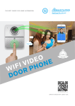
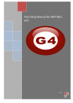
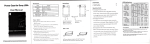
Contents
1、Introduction of product……………………………………………………………………………………………… 1
2、Installation ……………………………………………………………………………………………………………2
3、Port definition…………………………………………………………………………………………………………3
4、 Initial use and operation instruction………………………………………………………………………………4
5、Doorbell Setting………………………………………………………………………………………………………5
5.1、Add doorbell settings……………………………………………………………………………………………5
5.2、System settings…………………………………………………………………………………………………. 6
5.3、White list settings…………………………………………………………………………………………………7
5.4、Alarm settings………………………………………………………………………………………………
8
5.5、Equipment clock settings.……………………………………………………………………………………… 9
5.6、Interface settings………………………………………………………………………………………………….9
5.7、Wifi settings.………………………………………………………………………………………………………10
6、Introduce of functions………………………………………………………………………………………………11
6.1、Intercom ………………………………………………………………………………………………………… 11
6.2、Monitor. ……………………………………………………………………………………………………………12
6.3、Real-time Alerts.……………………………………………………………………………………………………13
6.4、Video replay ……………………………………………………………………………………………………. 14
6.5、Local pictures.………………………………………………………………………………………………………15
6.6、Visitors/Alarm record. ……………………………………………………………………………………………16
7、Software system settings …………………………………………………………………………………………… 17
8、Specification of product ……………………………………………………………………………………………… 18
9、Components …………………………………………………………………………………………………………… 19
1、Introduction of product
Wifi Visual intercom doorbell is a doorbell work with wifi . It connect with home wifi or wired LAN achieve two-way intercom between
doorbell and cell phone .When visitors press the doorbell ,doorbell sounds and meanwhile camera will start to work sending real-time
picture and call to smart phone . User receive the call and see the video to check who is outside ,can intercom with visitors and
remotely unlock door etc .
Wifi Visual intercom doorbell have alarm and remote control functions , make your home security has more powerful barrier . Advance
infrared light design make users can distinguish
the visitors in the evening. AC/DC power supply , eliminate the troubles of frequenty replacing battery .
2.4G wifi transmission systems , real-time video transmission , Audio and video data transmission band up to 100M band at most ,
Support Android OS and Iphone OS.One doorbell can connect with Multi cell phone at the same time . Make you and your family can
monitor home outdoor surroundings from anywhere .
Pass CE , RoHS certification.
Thank you for your support of this products , your satisfaction is our aim !
1
2、 Installation Diagram
open
surface
shell
from
midde plosition
+
3. Cover up the cover just
1. Switch four screws in the top part and bottom part . Open
2. Fix the doorbell and 86
the cover from middle position ,connect 12V/1A power wire .
box with screws.
2
opened , and install the 4 screws to
finish .
3、 Port Defination
Microphone
photoresistance
RJ45 port
Infrared light
Power Socket
Fixed the screw
Camera lens
LED light
PIR sensor
Work indicator LED
Reset switch
Speaker
Call button
Rear view
front view
Rear connection diagram
3
4、 Initial use and operation instructions
1. According to the installation diagram and connection diagram install doorbell , connect to power and lock to door bell .
2. Wait about one minutes , after speak “Sucessfully start system,welcome to smart home” .
3. Mobile phone Configuration :
1).Install wifi door phone APP in mobile . Press the doorbell button above 3 seconds , Doorbell enter in Configuration model , and give
a notice “Network configuration model now , set it down in 5mins” .
2).Open mobile’ wifi,connect to the hot spot named “BELL-00******” ,initial password is 123456789,.After connecting successfully,
open wifi door phone app again , press“ Add doorbell” , then click search or shake mobile ,when smart phone show a ID number ,
Click the ID number , then click”done”icon to finish.
3). First connected mobile Defaults to the administrator. If need to add more cellphone user , set up at administrator cellphone
phone .Enter into white list setting add user name and password (at most 8users including admin).
4. Network Configuration as soon as finishing “add door bell ID sucessfully”
:
1). Enter into wifi settings , add home wifi ,click "done”to finish
2).Insert internet cable to LAN port directly ,wifi setting is no need
5. Change administrator password : administrator cellphone enter into white list settings , click “admin user “, put into password click
“done”to finish .Notice :After set up administrator password , need to delete doorbell and add again by new password . Or
cell phone will notice wrong password .
6.
Each time change the admin, press “reset switch”at door bell back above 10S , can restore factory settings .
4
5、Door bell setting
5.1、Add door bell
1.Click add door bell
3.When search over LAN,pls make
sure mobile phone is the same LAN
with door bell device,then select the
target device,regular target device
name is bell+ ID number.
2.Can choose to manually input,
QR code scanning,or LAN
search to find the door bell and
add it
5
4.When operation is
complete,click”done”
to finish
5.2、System settings
1.Voice prompt switch : turn on or turn off . Turn on by factory
settings.
2.Configuration mode switch: turn on or turn off .Turn on by factory
settings.
3.Monitoring the maximum length of time : Range from 10 to 300 S.
4.Call maximum length of time: Range from 10 to 300 S.
5.Call waiting the maximum length of time : Range from 10 to 30 S.
6
5.3、White list settings
1.Administrator can add and delete other
cellphone user . Common cellphone user only
can Modify own password .Same user log in
different cell phone is not allowed .
2.Add new cellphone user
7
3.Modify user password
5.4、Alarm settings
1.When alarm turn off (Disarm )Any alarms are not notified to cellphone
2.When alarm turn on(Arming) User can set up other parameters further
A. Alarm type : Motion detection ,PIR and so on
B. 1-5
C. Alarm delay
D. Alarm effective time
8
5.5、Equipment clock settings
According to actual situation , set correct local time .Time automatically be same with internet
5.6、Port definition
Used to define extended IO control , as well as the linkage function.
1.Equipment time setting
2. Port setting
9
5.7、WiFi settings
.
1.Click setting icon enter into
setting interface
2.Click wifi setting enter
into wifi settings
10
3.Doorbell will show all
the valid routes in the list ,
select destination routing
(SSID)and click it to finish .
6、Function introduction
6.1、Intercom
1.Visitors press the door bell
2.Slide right or left side to
answer or hand up
11
3.Any cell phone answer it,others moblie will
automaticly hand up.In the precess of intercom,can
support taking video,picture,and remotely unlock
door.Press micphone on screen to send voice to
doorbell.Delay button can extend the talk
time.Ending a call can press”end call”button
6.2、Proactive Monitor
1.In main interface,directly click the
door bell device(online),user can
proactively monitor
2.In monitor interface,user can take
video,picture,but don’t support remotely
unlocking
12
6.3、Real-time alerts
1.when alarm accurs,all registered mobile phone will
receive instant notification,Slide green answer key,can
connect with door bell device and real time
monitor,slide red hand up key to hand up
2.Alarm monitoring
13
6.4、Video Replay
1..In process of intercom and
monitor,user can take videos.
2.Click“Video”file list,select object file.
14
3.Video playback,use a video player installed
in mobile phone for video playback,Storm
media player is recommended.
6.5、Local picture
1.select online door bell
device
2.Group and sort by time
15
3.Click to see larger
picture
6.6、Visitors/Alarm record
1.Navigate to record interface,select
a target device,visitors call and
alarm information are all saved
2.Overview
16
3.View the associated pictures
7、System setting
1.Navigate to above interface,click
“modify”button,appears tone
setting,software version etc
3.View software version
2.Set door bell ringtone
17
4.set alarm ringtone
8、Speclfications
Model
WIFI601
Camera
1/4”/F2.4/110°
Distinguishanility
420line
Illumination
2LUX
Light source
6pcs lnfeared light
Power
Standbay;DC 12V 1A
Powerdissipation
Stanbay;working;3.8W
Dimensions
120*96*34mm
18
9、Components in cluded
1.Outdoor camera
2.Screws(standard)
3.User manual
4.Power Supply
5.The interface line
6.IOS APP and Android APP for mobile
[NOSE]
(1)Our Company is committed to reform and innovation,and reserves the right to make changes and improvements without further
notice.Illustrations in this manual are for reference only.
(2)All warranty and liability is void should you or your dealer open the unit with out authorization or remove/deface the product labeling
(3)Warranty:For one year from purchasing this product,we promise to provide you with free maintenance and technical support.This
excludes damage during installation,unauthorized tampering and willful damage.
(4)Warranty periods different from this cannot be support by the manufacturer.
19