1
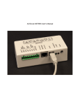
ACScout-NET User's Manual
Table of Contents
ACScout-NET User's Manual...................................................................................................................1
1 ACScout-NET Introduction....................................................................................................................3
1.1 General Description and Uses.........................................................................................................3
ACScout-NET Overview..................................................................................................................3
ACScout-NET GUI Overview..........................................................................................................3
1.2 ACScout-NET Package Contents....................................................................................................3
1.3 Specifications..................................................................................................................................4
2 Basic Operation.......................................................................................................................................5
2.1 Hardware Configuration..................................................................................................................5
2.2 ACScout-NET Connections.............................................................................................................5
2.3 GUI Description..............................................................................................................................6
3 Software Installation...............................................................................................................................7
3.1 ACScout GUI..................................................................................................................................7
3.2 USB drivers.....................................................................................................................................7
4 Configuration..........................................................................................................................................9
4.1 Connect to ACScout-NET...............................................................................................................9
4.2 Configure ACScout-NET..............................................................................................................11
Configure IP Address (Networking)...............................................................................................12
Configure Email..............................................................................................................................16
Configure Alarms...........................................................................................................................17
5 Application Notes..................................................................................................................................19
5.1 Send Text Messages (SMS Messages)..........................................................................................19
6 Company Information...........................................................................................................................20
6.1 About ACScout..............................................................................................................................20
6.2 Warranty........................................................................................................................................20
6.3 Contact Information......................................................................................................................20
1 ACScout-NET Introduction
1.1 General Description and Uses
ACScout-NET Overview
The ACScout-NET is a highly reliable, easy-to-use AC voltage monitor that plugs into an electrical
outlet. It records outages and variations in voltage and frequency. In addition to AC voltage monitoring
the ACScout-NET can monitor both internal and external temperature. The internal temperature is that
generated from inside of the ACScout-NET case. The external temperature is sensed with the supplied
thermistor assembly.
The ACScout-NET is able to report log files to your personal computer through USB or through your
network (Ethernet). The ACScout-NET has a list of predefined alarms that are reported in a log file.
These alarms are the ACScout-NET real-time measurements. For example, the Voltage Low alarm is
triggered when the AC voltage dips below a specified voltage value. The ACScout-NET may also send
out email messages, notifying you (in real-time) when these alarms have occurred.
Note that the ACScout-NET can only send email messages when power is present.
ACScout-NET GUI Overview
The ACScout-NET Graphical User Interface (GUI) is included with your purchase and must be
installed on a Windows personal computer (Microsoft Windows 2000™, Windows XP/XP Pro™,
VISTA™ or Windows 7™). The ACScout-NET GUI is used to configure network settings, email
settings, download log files, and define sensed alarms.
1.2 ACScout-NET Package Contents
Below is a list of the items that are included with your purchase of the ACScout-NET.
1.
2.
3.
4.
5.
ACScout-NET
ACScout Install CD
USB cable
AC Wall Adapter
External Thermistor Assembly (Temperature Monitoring)
1.3 Specifications
Characteristic
Notes
Rating
Units
Physical Dimensions:
Length
5
inch
Width
2.5
inch
Height
1
inch
Weight
8
oz
Nominal AC Voltage Min
100
Volts RMS
Nominal AC Voltage Max
135
Volts RMS
Operating Limits:
AC Voltage Min
AC sag detection
75
Volts RMS
AC Voltage Max
AC spike detection
180
Volts RMS
Temperature Min (non-condensing)
0
F
Temperature Max (non-condensing)
120
F
Voltage Detection Time (Min)
0.1
s
Frequency Detection Time (Min)
0.033
s
Nominal Frequency
60
Hz
Frequency Accuracy
+/- 0.2
Hz
Temperature Accuracy
+/- 5
F
Operating Accuracy:
2 Basic Operation
2.1 Hardware Configuration
The ACScout-NET should be connected as shown in Illustration 1. The ACScout-NET and your
personal computer are both connected to your router or network using Ethernet cable. The Wall
Adapter is plugged into the wall outlet and connected to the ACScout-NET. Do not plug the wall
adapter into a surge protection outlet, as it may affect the accuracy of the reading. If monitoring an
uninterruptible power supply (UPS), plug into the UPS output. (Note: the AC Wall Adapter is
calibrated to the specific ACScout-NET). USB cable must be temporarily used to connect your
computer to the ACScout-NET for configuration purposes.
Wall Outlet & AC
Wall Adapter
ACScout-Net
Router or
Network
Personal
Computer
Ethernet cable
AC voltage
USB cable (temporary)
Illustration 1: Basic ACScout-NET Configuration
2.2 ACScout-NET Connections
Illustration 2 shows the connectors on the front of the ACScout-NET. The green LED is activated
whenever power is supplied to the ACScout-NET. The red LED is activated when the ACScout-NET
detects that an event has occurred.
Ethernet Port
USB Port
9 Volts AC
I/O Expander
(External Temperature Sensor)
Event LED (Red)
Power LED (Green)
Illustration 2: ACScout-NET Connectors
2.3 GUI Description
The ACScout-NET has the ability to display AC voltage, frequency, and temperature readings in real
time (approximately every 2 seconds). Illustration 3 shows what the ACScout-NET GUI when the
ACScout-NET is connected to the computer. The GUI is made of primarily 3 sections: tab menus,
status bar, and log file. The tab menus are used to connect, configure, and request information from the
ACScout-NET. That status bar is located towards the top of the GUI and is highlighted green when a
connection has been established between the GUI and the ACScout-NET. When an active connection
exists, the status bar shows the real time values. The GUI also shows a log file that displays events
detected by the ACScout-NET.
Illustration 3: ACScout-NET GUI
3 Software Installation
3.1 ACScout GUI
To install the ACScout-NET GUI insert the ACScout software CD into the computer CD drive. The
CD should be automatically recognized and launch the Install Shield Wizard as shown in Illustration 4.
If Windows does not launch the Install Shield Wizard automatically then open the CD using Windows
Explorer and double click on the Setup.exe program. Continue to click “Next” until the installation has
completed.
Illustration 4: Install Shield Wizard (ACScout)
3.2 USB drivers
After installation of the ACScout-NET GUI is complete the Silicon Laboratories CP210x USB at
UART Bridge Driver Installer will be installed automatically as shown in Illustration 5. Click the
“Install” button and continue through the prompts until the installation is complete then reboot your
computer.
Illustration 5: USB Driver Installation
4 Configuration
After the ACScout-NET is connected to the computer via USB, the ACScout-NET will upload
voltage, frequency, and temperature readings in real time (approximately every 2 seconds). The GUI
also shows a log file that displays alarms
4.1 Connect to ACScout-NET
The initial ACScout-NET GUI screen is shown in Illustration 6. Notice that the GUI is not
connected to the ACScout-NET. Connect the USB cable between the ACScout-NET and your
computer, then click the “Manage” tab and select “Add Device”.
Illustration 6: Initial ACScout-NET GUI Screen
This will bring up the Add Device screen, shown in Illustration 7. Click on the check-box labeled
“Connect USB” and push the OK button.
Illustration 7: Add Device Screen
If an ACScout-NET is detected, then the log screen will change and show the device serial number
(in square brackets) followed by the real time voltage, frequency, and temperature measurements, as
shown in Illustration 8.
Illustration 8: ACScout-NET Detected Screen
To fully connect, click the “Manage” tab and select “Probe Device”. The Probe Device Screen will
pop-up where the ACScout-NET can be selected by choosing USB device from the drop down menu as
shown in Illustration 9.
Illustration 9: Probe Device Screen
When a connection is established the ACScout-NET GUI screen will appear like Illustration 10. The
status bar will change from displaying “Summary” to displaying the ACScout-NET voltage and
temperature readings. The status bar will also change from white to green. The log file is also
downloaded from the ACScout-NET showing the location, serial number and software version.
Illustration 10: ACScout-NET GUI Connected
4.2 Configure ACScout-NET
The ACScout-NET can be configured in multiple ways depending on your needs. This section
provides information with respect to configuring your ACScout-NET to work with your network, send
emails, and define sensing alarms for the AC voltage, frequency, and temperature.
Launch the configuration screen by clicking on the “Probe” tab and selecting “Configure”. This will
bring up the screen shown in Illustration 11. There are 4 tabs in this configuration screen: Info, Alarm,
IP Config, and Email. The info tag displays the ACScout-NET serial number, software version, date
and time, and location. The location should be modified to define where your ACScout-NET is
located. This is very useful when you are using multiple ACScout-NET units.
Illustration 11: Configuration Screen
Configure IP Address (Networking)
The ACScout-NET may be configured to operate with your network. This will enable the GUI to
modify the ACScout-NET configuration and receive log information through the Ethernet cable instead
of the USB cable.
To configure the ACScout-NET to be compatible with your network you will need some basic
information about your network to proceed. Specifically, you will need to have:
•
An IP Address that may be used by the ACScout-NET that is not currently being used by any
other device on your network.
•
Subnet Mask used by your network
•
Gateway used by your network
•
DNS Server used by your network
You may need to contact your network administrator for some of this information. If you are using
the ACScout-NET for home use then you should access your router to find an unused IP Address.
A convenient way to find some of your network settings is to use the command “ipconfig \all” in the
Windows command prompt. This can be done by clicking “Start” going to “Run” and typing “cmd”.
When the command prompt comes up you will be able to type in the command “ipconfig \all”.
Illustration 12 shows what you can expect to see after typing this command (Note: for best results make
sure that the computer is connected to your network via Ethernet cable). Please take note of your
Subnet Mask, Default Gateway, and DNS Server.
Illustration 12: Windows Command Prompt (ipconfig \all)
To modify the network setting click on the “IP Config” tab. Next enter in the Subnet Mask, Default
Gateway, DNS Server, and IP address as shown in Illustration 13. Note: the IP address must be
different than the IP address of the computer to which it is connected. Leave the port number at the
default (2100), unless you have a specific reason to change it. Click “OK” button to store the settings
on the ACScout-NET.
Note: After making configuration changes, reboot the ACScout-NET (power down then power up) to
insure that changes are loaded into active memory space.
Illustration 13: IP Configuration Screen
Test your network configuration by disconnecting the USB cable from your computer. The GUI will
indicate that the ACScout-NET is disconnected when the status bar changes to red and displays
“Connect failed” as shown in Illustration 14.
Illustration 14: ACScout-NET Disconnected
To connect using your network, plug the ACScout-NET into a router on your network using a
standard Ethernet cable and click the “Manage” tab and select “Add Device”. The Add Device screen
will pop-up. Enter the IP Address and port number that you used previously, as shown in Illustration
15.
Illustration 15: Add Device Screen
(Using IP Address)
Next click “Manage” tab and select “Probe Device”. Use the drop down menu to select the options
that has the IP Address in as shown in Illustration 16. Click “OK” button.
Illustration 16: Probe Device (Using IP Address)
Illustration 17 shows the main screen successfully connected. Notice that the status bar is green and
the log file is loaded.
Illustration 17: Successfully Connected
Configure Email
The ACScout-NET may be configured to send emails alerts, which is useful when you are not in the
same location as your ACScout-NET. This is done by using the ACScout-NET as an email server and
using your email address to send emails. The ACScout-NET can only use port 25 to send emails. An
existing SMTP server and email address is required to use this feature. Please contact your network
administrator or internet service provider if you do no have any of this information.
Illustration 18 shows an example of the email configuration screen. The following are descriptions
of the different options on this screen.
•
Email Address 1 – is an address that will receive and email from the ACScout-NET.
•
Email Address 2 – is a second address that will receive and email from the ACScout-NET.
•
SMTP Server – is the outgoing mail server used for sending email.
•
SMTP Port – is the outgoing mail server port used for sending email. (must be 25)
•
Username – is the email address that the ACScout-NET will use to send email.
•
Password – is the password for the email address that the ACScout-NET will use to send email.
•
Reply-to Address – is the reply-to email address that will be displayed in the email.
•
Subject Line – anything typed in here will be displayed in the subject of the email.
•
Body – anything typed in here will be added to the body of the email.
Illustration 18: Email Configuration Screen
Configure Alarms
The ACScout-NET has alarms that are triggered when the voltage spikes or sags, when frequency
drifts, or when the internal or external temperature goes to high or low. The min and max value that
triggers the alarm may be modified by clicking on the “Alarm” tab in the configuration screen. An
example of an Alarm configuration is shown in Illustration 19.
Illustration 19: Alarm Tab
The Alarm configuration is divided into 4 sections: Volts, Frequency, Internal Temperature, and
External Temperature. For each section an acceptable range can be defined by the high and low value.
When the ACScout-NET detects a value outside of this range then an alarm is triggered and the log file
is updated. If the email is configured properly, then an email message will be sent indicating which
alarm was triggered. Individual alarms can be deactivated by removing the check mark from the
“Enable” check box.
Note: The ACScout-NET maintains internal time and date referenced to Coordinated Universal Time
(UTC) often referred to as Greenwich Mean Time (GMT) or Zulu time. This is different than the time
and date displayed in the log file by the ACScout application on your computer which is converted
before being displayed to local time.
5 Application Notes
5.1 Send Text Messages (SMS Messages)
The ACScout-NET can be configured to send short-message-service (SMS) messages to your cell
phone. All major mobile phone carriers have an email address that feeds into your SMS inbox. The
only information that you need to is your phone number and your phone carriers email address. Table
1 shows a list of the more commonly used cell phone carriers.
Phone Carrier
Carriers Email Address
Sprint
@pm.sprint.com
Verizon
@vtext.com
T-Mobile
@tmomail.net
AT&T
@txt.att.net
Table 1: Cell Phone Carriers Email
To configure the ACScout-NET to send a text message make sure that the ACScout-NET is
connected to your computer and click “Probe” menu then go to “Configure”. To send a text message to
the cell phone number (614) 436-2300 that has Sprint as the carrier, you would enter
[email protected] into the Email Address 1 box under the Email tab as shown in Illustration
20. You can verify that this configuration works by unplugging the power to the ACScout-NET then
reconnecting it. You should receive a text message within the next few minutes indicating a power
failure.
Illustration 20: Text Messaging Configuration
6 Company Information
6.1 About ACScout
We are based in Columbus, Ohio and are proud to offer homeowners and businesses a simple,
affordable solution to AC power monitoring.
Founded and operated by pioneers in the electronics, computing and utility industries, we have more
than 100 years' experience building quality products.
On occasion, we build custom AC monitoring devices for special applications.
Don't hesitate to contact us with recommendations for ACScout enhancements, customization,
distribution, or sales. We appreciate your feedback and welcome your suggestions.
6.2 Warranty
All of our products come with a 5 year warranty from the time of purchase. Use the contact
information below if any issues are found with you ACScout product. The device will need to be
returned to factory for a replacement.
6.3 Contact Information
Website: www.acscout.com
Phone: (614) 436-2300
Address: 7020 Huntley Rd. Suite A, Columbus, OH 43229
Email: [email protected]