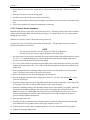
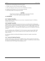
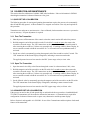
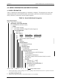
1
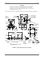
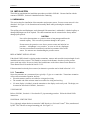
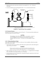
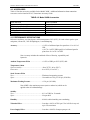
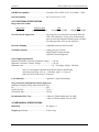
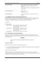
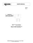
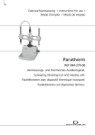
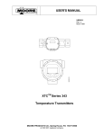
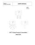
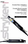
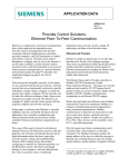
USER'S MANUAL
UM340W-1
Read this User's Manual
before reading UM340-1.
Rev: 2
February 2000
XTCTM Transmitters
Model 340W Venturi Flow Transmitter
UM340W-1
CONTENTS
TABLE OF CONTENTS
SECTION AND TITLE
PAGE
1.0 INTRODUCTION .......................................................................................................................1-1
1.1 PRODUCT DESCRIPTION ......................................................................................................1-1
1.2 EQUIPMENT DELIVERY AND HANDLING ..........................................................................1-1
2.0 INSTALLATION ........................................................................................................................2-1
2.1 MECHANICAL.........................................................................................................................2-1
2.1.1 Transmitter..........................................................................................................................2-1
2.1.2 Pressure Sensors..................................................................................................................2-2
2.1.2.1 Determining Sensor Depth.............................................................................................2-2
2.1.2.2 Pressure Sensor Installation...........................................................................................2-3
2.1.2.3 Pressure Sensor Removal ..............................................................................................2-4
2.2 ELECTRICAL...........................................................................................................................2-5
2.2.1 Two-Wire Transmitter .........................................................................................................2-5
2.2.2 Four-Wire Transmitter.........................................................................................................2-5
2.2.3 Transient & Lightning Protection .........................................................................................2-5
3.0 CALIBRATION AND MAINTENANCE...................................................................................3-1
3.1 QUICK SET-UP & CALIBRATION .........................................................................................3-1
3.1.1 Zero The Transmitter...........................................................................................................3-1
3.1.2 Span The Transmitter ..........................................................................................................3-1
3.2 ADVANCED SET-UP & CALIBRATION ................................................................................3-1
3.3 MAINTENANCE ......................................................................................................................3-2
4.0 MODEL DESIGNATION AND SPECIFICATIONS ................................................................4-1
4.1 MODEL DESIGNATION..........................................................................................................4-1
4.2 ACCESSORIES.........................................................................................................................4-2
4.3 PERFORMANCE SPECIFICATIONS ......................................................................................4-2
4.4 FUNCTIONAL SPECIFICATIONS ..........................................................................................4-3
4.5 MECHANICAL SPECIFICATIONS .........................................................................................4-3
4.6 HAZARDOUS AREA CLASSIFICATION/APPROVALS ........................................................4-4
4.6.1 CSA Hazardous Locations Precautions ................................................................................4-4
Changes for Revision 2 of this User’s Manual
Table 4-1 Model 340W, Model Designation was updated.
The Moore logo is a registered trademark of Moore Products Co. XTC and Smart Display are trademarks of Moore Products
Co.
All other trademarks are the property of their respective owners.
Moore Products assumes no responsibility for errors or omissions in this document or for the application and use of
information included in this document. The information herein is subject to change without notice.
February 2000
i
CONTENTS
ii
UM340W-1
February 2000
UM340W-1
INTRODUCTION
1.0 INTRODUCTION
This manual is for use with the Moore Products Co. Model 340W Venturi Flow Transmitter. It contains
installation, calibration and service information specific to the Model 340W.
Two User’s Manuals are included in a Model 340W shipment:
• UM340W-1, this manual, contains Model 340W specific information and references to sections in the
accompanying UM340-1.
• UM340-1, User’s Manual, XTC Transmitters, Series 340 Pressure Transmitter-Controllers contains
information that applies to all Series 340 Transmitters, such as:
- product support options (Section 1.4)
- installation wiring diagrams (Section 4)
- configuration procedures using the Model 275 Universal HART® Communicator and the local
magnetic switches (Section 6)
- troubleshooting techniques (Section 7)
Read UM340W-1 first since it contains the Model 340W specific information.
IMPORTANT
Save this User’s Manual for installing, configuring, operating, and
servicing a Model 340W transmitter.
1.1 PRODUCT DESCRIPTION
The Model 340W Venturi Flow Transmitter measures flow through a venturi primary flow element.
Designed specifically to retrofit existing BIF® SBF II Metering Systems, the Model 340W combines a
Moore Products Co. XTC Series differential pressure transmitter with two remote pressure sensors. These
sensors are either 10.5" (267 mm) or 14" (356 mm) long with a 0.75" (19 mm) diameter. They are
connected to the transmitter by an armored capillary system. A diagram of the transmitter is shown in
Figure 1-1 on the following page.
Each pressure sensor mounts into a venturi through an O-ring gland and valve assembly, called a
corporation cock. The sensor mounts flush with the inside of the venturi, and can be removed while the
venturi remains in service. Standard sensors have a 316 SS body and a 316L SS diaphragm.
The Model 340W is a smart transmitter that uses the HART protocol for communicating with other
devices, such as the Model 275 Communicator, other hand held configuration devices, and panel board
instruments.
The 4-20 mA output from the transmitter can be configured to be linear with differential pressure or flow.
This makes the Model 340W a direct replacement for any conventional or smart transmitter.
1.2 EQUIPMENT DELIVERY AND HANDLING
The capillary tubes and diaphragms can be damaged if the transmitter is mishandled. A kinked capillary or
damaged diaphragm can not be repaired. If damaged, the entire transmitter assembly must be returned to
the factory and the damaged parts replaced.
CAUTION
Never allow the transmitter or a pressure sensor to hang unsupported from the
armored capillary. This can result in permanent damage to the system.
February 2000
1-1
INTRODUCTION
UM340W-1
CAUTION
Do not remove the protective cover from a pressure sensor. A diaphragm is
very sensitive. A crease or nick in a diaphragm can cause measurement
inconsistencies and lead to premature failure of the sensor. Use extreme care
when handling the pressure sensors.
Refer to UM340-1, Section 4.1 for additional information concerning equipment delivery and handling.
5.46
(138.68)
4.39
(111.5)
1.75 (44.5)
Req'd to
Remove Cap
NEMA 4X
IP67/68
Enclosure
Electrical Entrance
1/2-14 NPT or
M20 X 1.5 Tapped
Hole, 2 Places
0.50
(12.7)
0.75 (19.1)
3.50
(88.9)
Dia
Armored
S.S.
Capillary
Fill Port
Sensor Connection
6.43
(163.3)
2.38
(60.5)
1
(25.4)
User
Selectable
2.13
(54.1)
Mounting
Bracket
48
(1219)
7/16-20 Tapped
Hole, 8 Places
10.5
(266.7)
316 S.S.
Sensor Body
0.750
(19.1)
3.13
(79.5)
3.56
(90.4)
3.50
(88.9)
2.75
(69.9)
3.50
(88.9)
0.745
(18.9)
2.75
(69.9)
0.760
(19.3)
316 S.S.
Diaphragm
1/4-20 thread,
Collars to Set Depth
1 place for
& Connect Linkage
linkage
Notes:
1. Dimensions are in inches (millimeters).
2. S.S.= Stainless Steel.
0.375
(9.5)
3.69
(93.7)
O-Ring
Seal
Retraction
Groove
7/16-20 Bolts
& Lockwashers
Included
Linkage
3/4 NPT
O-Ring
Gland Hex Head,
Cut Away
to Show Seal
1/4-20 Thread
6 places for
Connecting
Linkage
4.50
(114.3)
X03022S1
FIGURE 1-1 Model 340W Venturi Flow Transmitter
1-2
February 2000
UM340W-1
INSTALLATION
2.0 INSTALLATION
The following supplements the installation procedures provided in UM340-1. Become familiar with the
contents of UM340-1, Section 4.0 Installation before continuing.
2.1 MECHANICAL
This section describes installation of the transmitter and pressure sensors. Pressure sensor removal is also
described. See Figure 1-1 for dimensions and assembly details while performing the mechanical
installation.
The capillary tubes and diaphragms can be damaged if the transmitter is mishandled. A kinked capillary or
damaged diaphragm can not be repaired. The entire transmitter must be returned to the factory and the
damaged part replaced.
CAUTION
Never allow the transmitter or a pressure sensor to hang unsupported from the
armored capillary. This can result in permanent damage to the system.
Do not remove the protective cover from a pressure sensor until asked to in a
procedure. A diaphragm is very sensitive. A crease or nick in a diaphragm
can cause measurement inconsistencies and lead to premature failure of the
sensor. Use extreme care when handling the pressure sensors.
REPLACEMENT INSTALLATIONS
If the Model 340W at hand is replacing another transmitter, measure and record the insertion length of each
installed sensor before removal. This should be measured as the distance from the tip of the pressure
sensor to the stop collar. Be sure to clearly label each distance as the inlet or throat sensor dimension.
These dimensions will be needed in Section 2.1.2.2.
If the transmitter has already been removed, an alternative procedure can be found in Section 2.1.2.1.
2.1.1 Transmitter
Secure the transmitter to a permanent object, typically a 2" pipe or a venturi tube. Transmitter orientation
will not affect transmitter operation, however:
• Electrical entrances must be accessible for wiring and servicing.
• The terminal end of the enclosure must be accessible for wiring and servicing.
• If a smart display is included, orient the transmitter so the display can be easily read. The display can
be rotated as described in UM340-1, Section 4.6.
2" PIPE MOUNT
Refer to UM340-1, Section 4.4.1 for a detailed 2" pipe mounting procedure. Follow the Model 340D
instructions.
UNIVERSAL VENTURI TUBE
Use a right-angle adapter bracket to mount the 340W directly to a Universal Venturi® Tube, manufactured
by BIF. This Tube has an integral mounting pad. See Figure 2-1.
February 2000
2-1
INSTALLATION
UM340W-1
1. Mount the bracket to the venturi tube with four (4) user-supplied 5/16 - 18 x 1/2 bolts and
lockwashers.
2. Secure the transmitter to the mounting bracket with 7/16 - 20 x 3/4 bolts and lockwashers.
Model 340W
Min. Radius=
1 1/2" (38.1)
Capillary Tubing
TOP VIEW
HP
LP
Pressure
Sensor
O-Ring
Gland
Corp
Cock
Center Line of Tube
X03023S0
FIGURE 2-1 Typical Venturi Tube Installation
2.1.2 Pressure Sensors
Installed pressure sensors should appear as shown in Figure 2-1. This section provides installation and
removal procedures for the pressure sensors.
CAUTION
The diaphragm at the end of a pressure sensor is very sensitive. A crease or
nick in a diaphragm can cause measurement inconsistencies and lead to
premature failure of the sensor. Use extreme care when handling a pressure
sensor.
2.1.2.1 Determining Sensor Depth
If the required insertion length is not known, as in the case of a new installation, follow the procedure
below to determine the depth.
1. Following plant and process procedures, shut-off the process upstream of the venturi and empty the
venturi of any process material.
WARNING
Failure to perform the above step can expose personnel to hazardous process
material or to process material under high pressure or at extreme temperature.
2. Obtain a straight, stiff wire that is at least 13" (330 mm) long (e.g., a straightened metal coat hanger).
Form a 90º bend in one end, approximately 3/8" (10 mm) long.
3. Insert the hooked end of the wire through the O-ring gland and opened corporation cock until certain
the hooked end is into the venturi.
2-2
February 2000
UM340W-1
INSTALLATION
4. Slowly draw the wire out of the venturi until you feel the hook catch the edge. Hold the wire at this
point.
5. Mark the wire where it exits the O-ring gland.
6. Carefully remove the wire from the venturi and assembly.
7. Measure and record the required insertion length as the distance from the 90º bend to your mark on the
wire.
8. Follow this procedure for both the inlet and throat pressure taps.
2.1.2.2 Pressure Sensor Installation
Install the high pressure sensor in the inlet section pressure tap. The high pressure sensor can be located by
looking at the transmitter body, between the process flanges. A triangle with an ‘H’ in its center points to
the high pressure sensor.
Install the low pressure sensor in the throat section pressure tap.
To install a pressure sensor follow the procedure outlined below. This procedure assumes the venturi is
full and the corporation cock closed.
NOTE
The line pressure should be less than 50 psig (345 kPa) for installation or
removal of a pressure sensor to reduce the chance of personal injury.
1. On each pressure sensor, measure and mark the correct insertion depth as determined earlier (in Section
2.1 or 2.1.2.1). Mark the high pressure sensor with the inlet section insertion length. Mark the low
pressure sensor with the throat section insertion length.
2. Use a 3/16" Allen wrench to loosen the insertion depth (inner) collar and slide it forward to your mark.
Tighten the insertion depth collar. This collar sets the insertion depth for a flush mount with the inside
venturi wall.
3. Next loosen and move the restraining linkage (outer) collar to near the capillary end of the pressure
sensor. Placement of this collar is not critical at this point.
4. Remove the protective cover from the diaphragm end of the sensor.
5. Near the diaphragm end of the sensor, lightly grease about 1/2" (12 mm) of the sensor body - do not
grease the diaphragm.
6. Insert the pressure sensor into the O-ring gland until the groove on the sensor body is at the edge of the
O-ring gland. This will be a firm fit as the sealing O-ring is inside the gland.
7. Attach the restraining linkage to the restraining linkage (outer) collar and the O-ring gland. Adjust the
pivot points and restraining linkage collar as necessary so the linkage fits as shown in the lower
diagram in Figure 2-2. Hand-tighten the linkage bolts, the restraining linkage collar can be secured.
The restraining linkage prevents the sensor from being forced out of the assembly by the process
pressure during installation and removal.
8. Open the corporation cock.
9. Carefully push the pressure sensor the remaining distance into the assembly until the insertion depth
collar touches the O-ring gland as shown in the upper diagram in Figure 2-2.
10. Lock the pressure sensor in place by tightening the two set screws in the head of the O-ring gland.
11. Tighten all restraining linkage bolts.
February 2000
2-3
INSTALLATION
UM340W-1
12. Arrange any excess capillary. It may be draped over the transmitter. The minimum bend radius is 1
1/2" (12 mm). Never kink the capillary.
13. Perform the procedure for both the high and low pressure sensors.
Sensor in Operating Position
Corp Cock Open
Sensor Insertion
Depth Collar
O-Ring
Gland
Pressure Sensor
Capillary
Restraining
Linkage
O-Ring
Gland
Corp Cock
Sensor Withdrawn
Corp Cock Closed
Groove
Sensor Insertion
Depth Collar
Restraining
Linkage
X03024S1
FIGURE 2-2 Pressure Sensor Installation
2.1.2.3 Pressure Sensor Removal
The following procedure is for removing the pressure sensors and assumes that the pressure sensors are
completely inserted and the venturi is full of process material.
1. Check that the line pressure is less than 50 psig (345 kPa) for installation or removal of a pressure
sensor to reduce the chance of personal injury.
2. Loosen, but do not remove, the restraining linkage bolts.
3. Unlock the pressure sensor by loosening the set screws located in the head of the O-ring gland.
4. Carefully withdraw the pressure sensor until the restraining linkage is completely extended as shown in
the lower diagram in Figure 2-2.
CAUTION
Never pull a pressure sensor out by the capillary tubing. Always grip the end
of the pressure sensor.
5. The groove in the pressure sensor should now be visible at the O-ring gland. If it is not, adjust the
pressure sensor depth so the groove is just visible right at the O-ring gland edge.
6. Close the corporation cock.
2-4
February 2000
UM340W-1
INSTALLATION
7. Disconnect the restraining linkage from the O-ring gland.
8. Withdraw the pressure sensor from the assembly completely.
9. With a soft cloth gently clean the pressure sensor and diaphragm as necessary.
10. Promptly place the protective cover over the pressure sensor tip.
11. Repeat this procedure for the other pressure sensor.
CAUTION
Do not allow the transmitter or pressure sensors to hang from the armored
capillary. This can result in permanent damage to the system.
2.2 ELECTRICAL
2.2.1 Two-Wire Transmitter
Electrical installation of the transmitter as a two-wire device is described in Section 4.7 of UM340-1,
included with your shipment.
2.2.2 Four-Wire Transmitter
The Model 340W is a loop powered, two-wire device, however, successful operation, including remote
HART communication, has been accomplished by using the external power supply supplied with BIF SBF
II metering systems, Model 257 or 259. The input to this unit is 117 Vac, 50/60 Hz and the output is 24
Vdc for loop powered devices. This external unit essentially converts a two-wire transmitter to a four-wire
transmitter.
In retrofit installations where a BIF Model 257 or 259 external power supply exists, the Model 340W
positive and negative lead wires should be attached to the same terminals as the SBF II positive and
negative lead wires.
For information and help in specifying and installing other external power supplies, contact Moore
Products Co.
2.2.3 Transient & Lightning Protection
The Model 340W can have an optional, built-in lightning arrestor. Electrical connections to this unit are
the same as the non-lightning protected unit. Section 4.7 in UM340-1 has additional pre-cautions and notes
for installation and use of the integral transient/lightning arrestor.
February 2000
2-5
INSTALLATION
2-6
UM340W-1
February 2000
UM340W-1
CALIBRATION AND MAINTENANCE
3.0 CALIBRATION AND MAINTENANCE
This section describes calibration of a Model 340W after installation. Links to information in UM340-1
describing the transmitter’s advanced features are also given.
3.1 QUICK SET-UP & CALIBRATION
The following procedure for zeroing and spanning the transmitter requires the process to be momentarily
shut off and then fully opened. A Moore Products Co. magnetic screwdriver is the only tool required for
this procedure.
Transmitter zero and span are non-interactive. Once calibrated, check transmitter zero once a year and rezero as necessary. No span adjustment is required.
3.1.1 Zero The Transmitter
1. Shut the process off downstream of the venturi so that the venturi remains full and at line pressure.
2. Hold the magnetic end of the screwdriver on the Z switch for 5 seconds or more, then remove the
screwdriver from the target. The “PB” annunciator on the optional Smart Display should remain lit
after removing the screwdriver; if it does not, repeat this step. If working without a Smart Display, be
sure to count the seconds or hold the screwdriver for 7 or 8 seconds to be sure pushbutton mode is
activated.
3. Set the zero value by momentarily pressing the magnetic end of the screwdriver on the Z switch. The
“PB” annunciator on the Smart Display extinguishes, indicating a return to normal mode.
The applied pressure has now been stored as the LRV (lower range value) or 4 mA value.
3.1.2 Span The Transmitter
1. Open the control valve fully so the flowrate through the venturi is at the maximum, 100%, value.
2. Hold the magnetic end of the screwdriver on the FS switch for 5 seconds or more, then remove the
screwdriver from the target. The “PB” annunciator on the optional Smart Display should remain lit
after removing the screwdriver; if it does not, repeat this step. If working without a Smart Display, be
sure to count the seconds or hold the screwdriver for 7 or 8 seconds to be sure pushbutton mode is
activated.
3. Set the fullscale value by momentarily pressing the magnetic end of the screwdriver on the FS switch.
The “PB” annunciator on the Smart Display extinguishes, indicating a return to normal mode.
The applied pressure has now been stored as the URV (upper range value) or 20 mA value.
3.2 ADVANCED SET-UP & CALIBRATION
If the process can not be shut off and opened fully as outlined in the above procedure, a hand-held Model
275 HART Communicator will be needed to calibrate the instrument. A Communicator is required for
configuration of advanced features such as square root, characterizer and the operator display.
Refer to Section 6 and Appendix A in UM340-1 for use of the Communicator and descriptions of advanced
features of the transmitter.
February 2000
3-1
CALIBRATION AND MAINTENANCE
UM340W-1
NOTE
The square root extractor is frequently used in Model 340W applications.
The transmitter may be ordered with the square root extractor turned ON,
eliminating the need for the Communicator for configuration. The factory
default is for the transmitter to be shipped with the square root extractor
turned OFF.
3.3 MAINTENANCE
Section 7.0 of UM340-1 included with your shipment has complete details on service, maintenance and
troubleshooting of the transmitter. This section will deal strictly with service and maintenance of the
pressure sensors.
PRESSURE SENSOR CLEANING
Occasionally the sensing diaphragm on the pressure sensor may get coated with process material and need
to be cleaned. Clean a sensor by following the procedure below.
CAUTION
The diaphragms on the end of the pressure sensors are very sensitive.
Creases, nicks and dings in the diaphragm can cause measurement
inconsistencies and lead to premature failure of the sensor. Extreme care
should be taken when handling the pressure sensors.
1. Remove the pressure sensor from the process as described in Section 2.2.1.3 Pressure Sensor Removal.
WARNING
Some process material can be hazardous to personnel.
2. Clean the diaphragms using acetone, a mild soap and water solution, or chemical solvent required by
the process material.
3. Using tissue or a cotton ball, wipe the diaphragm clean making circular motions along the
convolutions.
4. Install the pressure sensor as described in Section 2.2.1.2 Pressure Sensor Installation.
PRESSURE SENSOR REPAIR
The pressure sensors are not field repairable. Return the entire transmitter to Moore Products Co. A failed
sensor will be repaired or replaced as necessary.
To return a Model 340W to Moore Products Co. for repair, refer to Section 7.10 in UM340-1.
3-2
February 2000
UM340W-1
MODEL DESIGNATION AND SPECIFICATIONS
4.0 MODEL DESIGNATION AND SPECIFICATIONS
4.1 MODEL DESIGNATION
Table 4-1 identifies the model designation on a transmitter’s nameplate. The nameplate also carries other
important information: bill of material number, serial number, span limits, maximum working pressure,
factory calibration, certifications, and user-supplied tagname.
TABLE 4-1 Model 340W, Model Designation
Basic Model Number
340W Venturi Flow Transmitter
Input Range: Span Limits Min/Max
D 10/450 inH2O (2.49 kPa/112 kPa)
Output
B 4-20 mAdc w/HART
C 4-20 mAdc w/HART & Integral Transient Suppressor
Process Diaphragms
S 316L SS
Body Parts (1)
Capillary Length
Wetted
Sensor Length
WA
316SS
10.5" (267 mm)
36" (660 mm)
WB
316SS
14" (356 mm)
48" (1219 mm)
YY
Special Features (Please Describe)
Fill Fluid
B Paratherm
Output Indicator
5 4-½ Digit SmartDisplay
N Not Required
Standard Options
N Not Required
Y Special Features (please describe)
Mounting Bracket
1 2" Pipe Mount Bracket with SS Hardware
2 Universal Bracket
3 2" Pipe Mount 316SS Bracket
4 BIF® SBF II Adapter Bracket (mounts directly to venturi)
N Not Required
Housing
1 Aluminum 1/2" - 14 NPT
2 Aluminum M20 x 1.5 (2)
Hazardous Area Classifications (3)
N Non-Approved
3 FM/CSA All
340W D B
1.
2.
3.
S WB B 5
N
1
1
3
Sample Model Number
Insertion depth collars, restraining linkage, and restraining linkage collars included with each unit. Corporation cocks and
O-ring glands available separately.
Not available with FM/CSA units.
Hazardous area approvals pending. Consult Moore Products Co. for availability.
February 2000
4-1
MODEL DESIGNATION AND SPECIFICATIONS
UM340W-1
4.2 ACCESSORIES
Table 4-2 lists the accessories available for the Model 340W. Additional information about transmitter
accessories can be found in PI34-3, Transmitter Accessory Guide.
TABLE 4-2 Model 340W Accessories
DESCRIPTION
Corporation Cock
SBF II Adapter Bracket Kit
2” Pipe Mount Bracket Kit
O-Ring Gland
Model 275 Universal HART Communicator
PART NUMBER
Consult factory
16275-163
15965-619
16275-220
275D9EISB0100
4.3 PERFORMANCE SPECIFICATIONS
Reference conditions: zero-based spans, ambient temperature 28°C (82°F), D/A trim values equal to span
end points, silicone fill, 316L SS diaphragms, 1 second damping.
Accuracy........................................................... ± 0.25% of calibrated span for spans from 1:1 to 10:1 of
URL
± (0.178 + 0.0072 [URL/span])% of calibrated span for
spans from 10:1 to 45:1 of URL
Note: Accuracy includes the combined effects of linearity, repeatability and
hysteresis.
Ambient Temperature Effect ........................... ± 0.25% of URL per 28°C (82°F) shift
Temperature Limits
Sensor Assembly ................................................ -40 to 257°F (-40 to 125°C)
Electronics ........................................................ 0 to 130°F (-18 to 54°C)
Static Pressure Effect
Zero................................................................... Eliminated at operating pressure
Span .................................................................. Correctable to 0.2% per 150 psi (1034 kPa)
Maximum Working Pressure ........................... ± 150 psi (1034 kPa)
Note: MWP is the maximum pressure (static or otherwise) which can be
applied to the cell without damage.
Stability
Zero................................................................... 0.1% of URL for 12 months
Span .................................................................. No span drift
Humidity........................................................... 0-100% relative humidity, non-condensing
Vibration Effect................................................ Less than ± 0.05% of URL per G for 0-60 Hz in any axis
up to 2 Gs maximum
Power Supply Effect......................................... Less than ± 0.005% of output span per volt
4-2
February 2000
UM340W-1
MODEL DESIGNATION AND SPECIFICATIONS
EMI/RFI Susceptibility .................................... Less than 0.25% of URL at 30 V/m, 30 MHz - 1 GHz
ESD Susceptibility............................................ IEC severity level 4, 15 kV
4.4 FUNCTIONAL SPECIFICATIONS
Range and Sensor Limits
Range Code
D
Minimum Span
10 inH2O (2.49 kPa)
LRL
-450 inH2O (-112 kPa)
URL
450 inH2O (112 kPa)
Zero Elevation & Suppression ......................... The range may be set anywhere between the LRL and
URL of the transmitter, as long as the calibrated span
does not exceed the minimum allowable span (see table).
Zero and span in the XTC are non-interactive.
Electronic Damping.......................................... Adjustable between 0 and 30 seconds
Transmitter Outputs ........................................ Analog, two-wire 4-20 mA
Digital, HART Communications
Optional Transient Suppressor
Power Supply Requirements
Minimum Terminal to Terminal Compliance Voltage.......+10 Vdc
Maximum Terminal to Terminal Voltage.........................+42 Vdc
Maximum Load ..............................................................RL = 50*(supply voltage) - 500 ohms
Note: To ensure digital Communications, HART imposes the following
restrictions on the loop: 250< RL < 1100 ohms, ripple < 0.2 Vp-p ac
between 47 and 125 Hz, noise < 0.6 mVrms.
Local Indication................................................ Optional 4-½ digit Smart Display
Surge Protection (with optional transient suppressor)
Maximum Clamping Voltage (either terminal to case)
DC .................................................................... 68V
100 kV/µS surge ................................................ 70 Vp
1000 kV/µS surge .............................................. 120 Vp
Recommended Wire Type................................ <5000 ft: (1524m) Belden 8641, 24 AWG
>5000 ft (1524m): Belden 8762, 20 AWG
4.5 MECHANICAL SPECIFICATIONS
Dimensions ....................................................... See Figure 1-1
Weight (approximate)........................................ 8 lbs (3.6 kg)
February 2000
4-3
MODEL DESIGNATION AND SPECIFICATIONS
UM340W-1
Electronics Housing.......................................... Epoxy Powder Coated, Low Copper Cast Aluminum
NEMA 4X, IP66/68 (submersible up to 3 meters,
indefinitely)
(2) 1/2" - 14 NPTF Electrical Conduit Entrances (M20 x
1.5 optional)
Process Wetted Parts ....................................... Body: 316 SS
Diaphragm: 316L SS
Process Connection .......................................... (2) 0.75" diameter by 10.5” pressure sensors (14.5"
optional)
4.6 HAZARDOUS AREA CLASSIFICATION/APPROVALS
The Model 340W is designed to meet the following approvals and standards. Before installing, applying
power to, or servicing a transmitter, see the transmitter’s nameplate and Table 4.1 for electrical
classification. Contact Moore Products Co. for latest approvals and certifications.
CE Approval
FM/CSA Approval:
Intrinsically Safe:
Explosion Proof:
Non-Incendive:
Class I, Division 1, Groups A, B, C and D
Class II, Division 1, Groups E, F and G
Class III, Division 1
Class I, Division 1, Groups A, B, C and D
Class II, Division 1, Groups E, F and G
Class III, Division 1
Class I, Division 2, Groups A, B, C and D
4.6.1 CSA Hazardous Locations Precautions
This section provides CSA hazardous location precautions that should be observed by the user when
installing or servicing the equipment described in this manual. These statements supplement those given in
the preceding section.
WARNING
Failure to observe the following precautions could result in an explosion
hazard.
Precautions - English
For Class I, Division 1 and Class I, Division 2 hazardous locations:
•
Use only factory-authorized replacement parts. Substitution of components can impair the suitability of
this equipment for hazardous locations.
For Division 2 hazardous locations:
When the equipment described in this Instruction in installed without safety barriers, the following
precautions should be observed. Switch off electrical power at its source (in non-hazardous location) before
connecting or disconnecting power, signal, or other wiring.
4-4
February 2000
UM340W-1
MODEL DESIGNATION AND SPECIFICATIONS
Précautions - Français
Emplacements dangereux de classe I, division 1 et classe I, division 2:
•
Les pièces de rechange doivent être autorisées par l’usine. Les substitutions peuvent rendre cet appareil
impropre à l’utilisation dans les emplacements dangereux.
Emplacement dangereux de division 2:
Lorsque l’appareil décrit dans la notice ci-jointe est installé sans barrières de sécurité, on doit couper
l’alimentation électrique a la source (hors de l’emplacement dangereux) avant d’effectuer les opérations
suivantes branchment ou débranchement d’un circuit de puissance, de signalisation ou autre.
n
February 2000
4-5
Process Automation Solutions
For prompt, personal attention to your instrumentation and control needs, contact the Moore
Products Co. location nearest you. Information on other Moore Products Co. representatives
in your area is available from these regional locations.
www.moore-solutions.com
AUSTRALIA
FRANCE
SINGAPORE
(Australia) Pty. Ltd.
Federation Business Centre
Unit 27, 198 Young Street
Waterloo, NSW, 2017
Tel: +61 2 9319 4877
Fax: +61 2 9318 1743
22 rue Vladimir Jankelevitch
Emerainville, 77437 Marne la vallée
cedex 2
France
Tel: +33 1 64 61 68 68
Fax: +33 1 64 61 67 34
70 Bendemeer Road
#03-01 Hiap Huat House
Singapore 339940
Tel: +65 299 6051
Fax: +65 299 6053
THE BENELUX
INDIA
Wagenmakerstraat 3
2984 BD RIDDERKERK
Tel: +31 180 461111
Fax: +31 180 461132
34/35, MIDC Estate
“H” Block
Pimpri, Pune 411 018
Tel: +91 212 770171
Fax: +91 212 777049
Moore House
39 Monza Place
Kyalami Business Park
Midrand
Tel: +27 11 466 1673/9
Fax: +27 11 466 1618
ITALY
UNITED KINGDOM
Via S. Aleramo 2
20063 Cernusco sul Naviglio (Milano)
Tel: +39 02 929054 1
Fax: +39 02 92905454
Copse Road
Lufton Industrial Estate
Yeovil, Somerset BA22 8RN
Tel: +44 1935 706262
Fax: +44 1935 706969
SOUTH AFRICA
CANADA
P.O. Box 370
Brampton, Ontario L6V 2L3
Tel: +1 905 457 9638
Fax: +1 905 457 4182
CHINA
Kerry Everbright City
Unit 7, 12/F, Tower 1
218 Tian Mu Xi Lu, Zhabei District
Shanghai 200070
Tel: +86 21 6354 9879, +86 21 6354
5094 or +86 21 6354 1076
Fax: +86 21 6354 3017
MEXICO
UNITED STATES
Tintoreto No. 32-302
Col. Nonoalco Mixcoac
Mexico, D.F.
C.P. 03910
Tel: +52 5 611 9858
+52 5 615 1948
+52 5 615 0262
+52 5 615 0238
Fax: +52 5 611 4541
Printed on post-consumer recycled paper.
1201 Sumneytown Pike
Spring House, PA 19477-0900
Tel: +1 215 646 7400
Fax: +1 215 283 6358
Feb 2000