1
6 / 2011
www.klinkmann.com
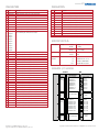
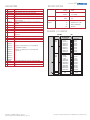
PARAMETERS
SPECIFICATIONS
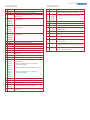
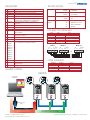
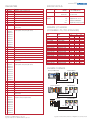
No. Name
Description
Communications
01
DPI Port
Displays the port to which the adapter is connected.
02
DPI Data Rate
Displays the data rate (kilobits per second) used by the drive.
03
DF1 Addr Cfg
Sets the node address if the Data Rate switch is set to “PGM” (Program).
04
DF1 Addr Act
Displays the node address actually used by the adapter.
05
DF1 Rate Cfg
Sets the data rate (kilobits per second) at which the adapter
communicates when the Data Rate switch is set to “PGM” (Program).
06
DF1 Rate Act
Displays the data rate (bits or kilobits per second) actually used
by the adapter.
Network
Protocol
DF1
Data Rates
Drive
1200 - 38400 bps
Protocol
DPI
Data Rates
Electrical
Consumption
125 or 500 Kbps
Drive (DPI)
150 mA at 5 VDC
Network
07
Ref/Fdbk Size
Displays the size of the Reference/Feedback words.
08
Datalink Size
Displays the size of each Datalink word.
09
Reset Module
Used to reset the adapter or reset defaults.
10
Comm Flt Action
Sets the action that the adapter will take if it detects that communications
have been disrupted.
11
Active Cfg
Displays the source from which the adapter node address and data rate are
taken (switches or parameters).
12
DPI I/O Cfg
Selects the I/O that is transferred through the adapter.
13
DPI I/O Act
Displays the I/O that the adapter is actively transmitting.
14
Flt Cfg Logic
15
Flt Cfg Ref
Sets the data that is sent to the drive if Parameter 10 - [Comm Flt Action]
is set to “Send Flt Cfg” and communications are disrupted.
16
Flt Cfg A1 In
17
Flt Cfg A2 In
18
Flt Cfg B1 In
19
Flt Cfg B2 In
20
Flt Cfg C1 In
21
Flt Cfg C2 In
22
Flt Cfg D1 In
23
Flt Cfg D2 In
24
CRC/BCC Cfg
Sets the method for error detection (BBC or CRC) in data communications.
25
CRC/BCC Act
Displays the actual error detection method (BBC or CRC)used for
data communications.
26
Dup Msg Detect
Determines if the adapter ignores duplicate messages.
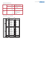
N/A
Regulatory
UL
Compliance
cUL
UL508C
CAN/CSA C22.2 No. 14-1791
CE
EN50178 and EN61800-3
CTick
EN61800-3
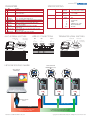
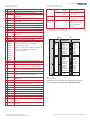
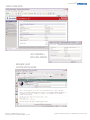
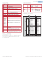
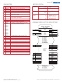
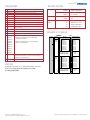
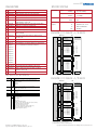
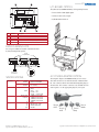
CONNECTOR TERMINALS
O
M
SH
IE
G LD
N
D
B
C
RM
A
TE
B
Node “n”
C
O
M
SH
IE
G LD
N
D
A
TE
RM
O
M
SH
IE
G LD
N
D
B
Node 2
C
A
RM
Node 1
TE
Function
Signal RC Termination
TxRxDx TxRxDx +
Signal Common
Shield RC Termination
Shield Ground Termination
Signal
Termination
Signal A
Signal B
Common
Shield
Ground
Terminal
TERM
A
B
COM
SHIELD
GND
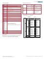
N-FILE SUMMARY
Data Category
Explicit Messaging
I/O Messaging
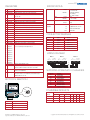
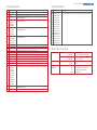
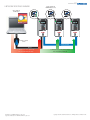
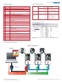
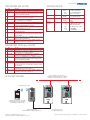
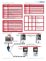
EXAMPLE SYSTEM
Description
Block Transfer Emulation
Logic Command/Status
Reference/Feedback
Datalinks A-D
Comms Time-Out Value
N-File Address
N40:0-63
N41:0
N41:1-2
N41:3-18
N42:3
DPI Port Config
PowerFlex 70 Drives with
20-COMM-S Adapters (Port 5)
Laptop or Desktop PC
with DriveExplorer
20-COMM-S
SERIES A
FRN AS SHIPPED: V 1.001
SERIAL NUMBER: 402D9423
DEVICE: 5VDC 150mA
LISTED
IND.CONT.EQ.
966X
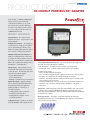
20-COMM-S
SERIES A
N223
FRN AS SHIPPED: V 1.001
SERIAL NUMBER: 402D9423
DEVICE: 5VDC 150mA
LISTED
IND.CONT.EQ.
966X
NODE ADDRESS
A
SERIES A
COM SHIELD GND
DATA
RATE
TERM
PORT
MOD
NET A
NET B
A
DFI RS485
B
COM SHIELD GND
DATA
RATE
TERM
PORT
0.00 Hz
2.5 Cans/Sec
646.0 Bus/Volt
MOD
NET A
NET B
A
B
COM SHIELD GND
DATA
RATE
PORT
0.00 Hz
2.5 Cans/Sec
646.0 Bus/Volt
MOD
NET A
NET B
STS
0.00 Hz
2.5 Cans/Sec
646.0 Bus/Volt
STS
PC Cable
STS
N223
NODE ADDRESS
DFI RS485
B
FRN AS SHIPPED: V 1.001
SERIAL NUMBER: 402D9423
DEVICE: 5VDC 150mA
LISTED
IND.CONT.EQ.
966X
NODE ADDRESS
DFI RS485
TERM
20-COMM-S
N223
1203-USB or 1203-SSS
Converter
RS485 DF1 Network
Drive Cable
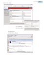
Use DriveExplorer Lite or Full to configure a single
drive and its installed RS485 DF1 adapter
Publication 20COMM-PP001F-EN-P – May 2008
Supersedes Publication 20COMM-PP001E-EN-P – July 2006
Use DriveExplorer Full to route through DPI and configure
drives connected directly on RS485 DF1 (Up to 254 drives!)
Copyright ©2008 Rockwell Automation, Inc. All Rights Reserved. Printed in USA.