1
SECTION 2
SIGNAL DESCRIPTION
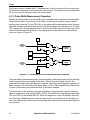
This section contains descriptions of the input and output signals. The input and output
signals can be functionally organized into groups as shown in Figure 2-1. The following
paragraphs provide a brief description of the signal and a reference (if applicable) to other
sections that contain more detail about its function.
NOTE
Assertion and negation are used to specify forcing a signal to a
particular state. Assertion and assert refer to a signal that is
active or true. Negation and negate refer to a signal that is
inactive or false. These terms are used independently of the
voltage level (high or low) that they represent.
POWER
SUPPLY
VCC
GND
GPIP
CLK
D0 – D7
ASYNCHRONOUS
BUS CONTROL
DATA BUS
CS
DS
R/W
DTACK
RS1 – RS5
MC68HC901
MULTI-FUNCTION
PERIPHERAL
(MFP)
TAI
TBI
TAO
TBO
TCO
TDO
XTAL1
XTAL2
TIMER
CONTROL
SI
SO
RC
TC
SERIAL I / O
CONTROL
RR
TR
DMA
CONTROL
REG SEL
RESET
INTERRUPT
CONTROL
I0 – I7
IRQ
IACK
IEI
IEO
Figure 2-1. Input and Output Signals
2.1 POWER SUPPLY (VCC and
GND)
FIGURE - INPUT AND OUTPUT SIGNALS
/ AD
Power is supplied to the MFP using theseMC68HC901UM
connections.
The VCC pin is powered at +5 volts,
and ground is connected to the GND pins.
MOTOROLA
MC68HC901 USER’S MANUAL
2-1