1
man pages section 7: Device and
Network Interfaces
Sun Microsystems, Inc.
4150 Network Circle
Santa Clara, CA 95054
U.S.A.
Part No: 817–0700–10
December 2003
Copyright 2003 Sun Microsystems, Inc.
4150 Network Circle, Santa Clara, CA 95054 U.S.A.
All rights reserved.
This product or document is protected by copyright and distributed under licenses restricting its use, copying, distribution, and decompilation. No
part of this product or document may be reproduced in any form by any means without prior written authorization of Sun and its licensors, if any.
Third-party software, including font technology, is copyrighted and licensed from Sun suppliers.
Parts of the product may be derived from Berkeley BSD systems, licensed from the University of California. UNIX is a registered trademark in the U.S.
and other countries, exclusively licensed through X/Open Company, Ltd.
Sun, Sun Microsystems, the Sun logo, docs.sun.com, AnswerBook, AnswerBook2, and Solaris are trademarks, registered trademarks, or service marks
of Sun Microsystems, Inc. in the U.S. and other countries. All SPARC trademarks are used under license and are trademarks or registered trademarks
of SPARC International, Inc. in the U.S. and other countries. Products bearing SPARC trademarks are based upon an architecture developed by Sun
Microsystems, Inc.
The OPEN LOOK and Sun™ Graphical User Interface was developed by Sun Microsystems, Inc. for its users and licensees. Sun acknowledges the
pioneering efforts of Xerox in researching and developing the concept of visual or graphical user interfaces for the computer industry. Sun holds a
non-exclusive license from Xerox to the Xerox Graphical User Interface, which license also covers Sun’s licensees who implement OPEN LOOK GUIs
and otherwise comply with Sun’s written license agreements.
Federal Acquisitions: Commercial Software–Government Users Subject to Standard License Terms and Conditions.
DOCUMENTATION IS PROVIDED “AS IS” AND ALL EXPRESS OR IMPLIED CONDITIONS, REPRESENTATIONS AND WARRANTIES,
INCLUDING ANY IMPLIED WARRANTY OF MERCHANTABILITY, FITNESS FOR A PARTICULAR PURPOSE OR NON-INFRINGEMENT, ARE
DISCLAIMED, EXCEPT TO THE EXTENT THAT SUCH DISCLAIMERS ARE HELD TO BE LEGALLY INVALID.
Copyright 2003 Sun Microsystems, Inc.
4150 Network Circle, Santa Clara, CA 95054 U.S.A.
Tous droits réservés.
Ce produit ou document est protégé par un copyright et distribué avec des licences qui en restreignent l’utilisation, la copie, la distribution, et la
décompilation. Aucune partie de ce produit ou document ne peut être reproduite sous aucune forme, par quelque moyen que ce soit, sans
l’autorisation préalable et écrite de Sun et de ses bailleurs de licence, s’il y en a. Le logiciel détenu par des tiers, et qui comprend la technologie relative
aux polices de caractères, est protégé par un copyright et licencié par des fournisseurs de Sun.
Des parties de ce produit pourront être dérivées du système Berkeley BSD licenciés par l’Université de Californie. UNIX est une marque déposée aux
Etats-Unis et dans d’autres pays et licenciée exclusivement par X/Open Company, Ltd.
Sun, Sun Microsystems, le logo Sun, docs.sun.com, AnswerBook, AnswerBook2, et Solaris sont des marques de fabrique ou des marques déposées, ou
marques de service, de Sun Microsystems, Inc. aux Etats-Unis et dans d’autres pays. Toutes les marques SPARC sont utilisées sous licence et sont des
marques de fabrique ou des marques déposées de SPARC International, Inc. aux Etats-Unis et dans d’autres pays. Les produits portant les marques
SPARC sont basés sur une architecture développée par Sun Microsystems, Inc.
L’interface d’utilisation graphique OPEN LOOK et Sun™ a été développée par Sun Microsystems, Inc. pour ses utilisateurs et licenciés. Sun reconnaît
les efforts de pionniers de Xerox pour la recherche et le développement du concept des interfaces d’utilisation visuelle ou graphique pour l’industrie
de l’informatique. Sun détient une licence non exclusive de Xerox sur l’interface d’utilisation graphique Xerox, cette licence couvrant également les
licenciés de Sun qui mettent en place l’interface d’utilisation graphique OPEN LOOK et qui en outre se conforment aux licences écrites de Sun.
CETTE PUBLICATION EST FOURNIE “EN L’ETAT” ET AUCUNE GARANTIE, EXPRESSE OU IMPLICITE, N’EST ACCORDEE, Y COMPRIS DES
GARANTIES CONCERNANT LA VALEUR MARCHANDE, L’APTITUDE DE LA PUBLICATION A REPONDRE A UNE UTILISATION
PARTICULIERE, OU LE FAIT QU’ELLE NE SOIT PAS CONTREFAISANTE DE PRODUIT DE TIERS. CE DENI DE GARANTIE NE
S’APPLIQUERAIT PAS, DANS LA MESURE OU IL SERAIT TENU JURIDIQUEMENT NUL ET NON AVENU.
030827@6671
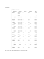
Contents
Preface
11
Introduction
Intro(7)
17
18
Device and Network Interfaces
adp(7D)
21
22
adpu320(7D)
afb(7d)
26
arp(7P)
27
asy(7D)
29
ata(7D)
32
audio(7I)
24
36
audiocs(7D)
47
audioens(7D)
51
audio_support(7I)
audiots(7D)
55
57
authmd5h(7M)
60
authsha1(7M)
61
bbc_beep(7D)
62
bd(7M)
63
bge(7D)
65
bpp(7D)
68
bufmod(7M)
bwtwo(7D)
73
77
3
cadp160(7D)
cadp(7D)
78
79
cdio(7I)
83
ce(7D)
91
cgeight(7D)
95
cgfour(7D)
96
cgfourteen(7D)
cgsix(7D)
97
98
cgthree(7D)
99
cgtwo(7D)
100
chs(7D)
101
cmdk(7D)
102
connld(7M)
103
console(7D)
104
cpr(7)
105
cvc(7D)
107
cvcredir(7D)
108
dad(7D)
109
dbri(7D)
112
devfs(7FS)
118
devinfo(7D)
dkio(7I)
119
120
dlcosmk(7ipp)
dlpi(7P)
129
130
dman(7D)
131
dmfe(7D)
134
dnet(7D)
136
dpt(7D)
dr(7d)
138
140
dscpmk(7ipp)
e1000g(7D)
ecpp(7D)
148
elx(7D)
154
elxl(7D)
156
encr3des(7M)
encraes(7M)
encrbfsh(7M)
encrdes(7M)
4
142
143
158
159
160
161
man pages section 7: Device and Network Interfaces • December 2003
eri(7D)
162
esp(7D)
166
fas(7D)
172
fbio(7I)
180
fcip(7D)
182
fcp(7D)
185
fctl(7D)
186
fd(7D)
187
fdio(7I)
193
ffb(7D)
197
flowacct(7ipp)
fp(7d)
199
FSS(7)
200
ge(7D)
203
198
gld(7D)
207
glm(7D)
217
gpio_87317(7D)
grbeep(7d)
hci1394(7D)
224
hdio(7I)
225
hid(7D)
227
hme(7D)
229
hpfc(7D)
234
hsfs(7FS)
236
hubd(7D)
239
i2o_bs(7D)
241
i2o_scsi(7D)
243
icmp6(7P)
icmp(7P)
244
246
idn(7d)
248
ieef(7D)
251
ifb(7d)
253
ifp(7D)
254
if_tcp(7P)
inet6(7P)
inet(7P)
ip6(7P)
ip(7P)
222
223
258
265
268
271
277
Contents
5
ipgpc(7ipp)
282
ipqos(7ipp)
284
iprb(7D)
286
ipsec(7P)
289
ipsecah(7P)
293
ipsecesp(7P)
294
isdnio(7I)
296
isp(7D)
309
kb(7M)
315
kdmouse(7D)
kstat(7D)
324
325
ksyms(7D)
326
ldterm(7M)
le(7D)
328
331
llc1(7D)
335
llc2(7D)
338
lockstat(7D)
lofi(7D)
344
345
lofs(7FS)
346
log(7D)
348
logi(7D)
352
lp(7D)
353
ltem(7D)
355
m64(7D)
356
md(7D)
357
mediator(7D)
mem(7D)
mhd(7i)
364
366
mixer(7I)
371
mpt(7D)
381
msglog(7D)
msm(7D)
mt(7D)
mtio(7I)
361
386
387
388
389
ncrs(7D)
401
null(7D)
408
ocf_escr1(7D)
ocf_ibutton(7D)
6
409
410
man pages section 7: Device and Network Interfaces • December 2003
ocf_iscr1(7D)
ohci(7D)
411
412
openprom(7D)
pcata(7D)
414
419
pcelx(7D)
421
pcfs(7FS)
423
pcic(7D)
428
pckt(7M)
430
pcmem(7D)
pcn(7D)
431
432
pcram(7D)
434
pcscsi(7D)
437
pcser(7D)
438
pfb(7D)
440
pf_key(7P)
441
pfmod(7M)
451
pipemod(7M)
454
pln(7D)
455
pm(7D)
456
poll(7d)
460
prnio(7I)
465
ptem(7M)
469
ptm(7D)
470
pts(7D)
472
pty(7D)
474
qfe(7d)
477
qlc(7D)
481
quotactl(7I)
482
ramdisk(7D)
484
random(7D)
486
rarp(7P)
488
rns_smt(7D)
route(7P)
489
490
routing(7P)
sad(7D)
sbpro(7D)
494
496
499
scman(7D)
504
scmi2c(7d)
507
Contents
7
sc_nct(7D)
508
scsa2usb(7D)
509
scsi_vhci(7D)
513
sd(7D)
516
se(7D)
522
se_hdlc(7D)
ses(7D)
529
sesio(7I)
sf(7D)
526
531
532
sgen(7D)
534
sk98sol(7D)
skfp(7D)
540
546
slp(7P)
548
soc(7D)
550
socal(7D)
552
sockio(7I)
554
sppptun(7M)
spwr(7D)
ssd(7D)
st(7D)
555
556
557
562
stc(7D)
577
stp4020(7D)
589
streamio(7I)
590
su(7D)
606
sxp(7D)
609
symhisl(7D)
612
sysmsg(7D)
615
tcp(7P)
616
tcx(7D)
621
termio(7I)
623
termiox(7I)
ticlts(7D)
644
650
timod(7M)
652
tirdwr(7M)
654
tmpfs(7FS)
656
tokenmt(7ipp)
tpf(7D)
661
tswtclmt(7ipp)
8
658
662
man pages section 7: Device and Network Interfaces • December 2003
ttcompat(7M)
tty(7D)
663
672
ttymux(7D)
673
tun(7M)
674
uata(7D)
678
udfs(7FS)
680
udp(7P)
681
ufs(7FS)
684
uhci(7D)
687
usba(7D)
688
usb_ac(7D)
690
usb_ah(7M)
694
usb_as(7D)
695
usbkbm(7M)
697
usb_mid(7D)
699
usbms(7M)
700
usbprn(7D)
702
uscsi(7I)
707
usoc(7D)
711
visual_io(7I)
volfs(7FS)
713
719
vuidmice(7M)
wrsm(7D)
721
724
wrsmd(7D)
726
wscons(7D)
727
xmemfs(7FS)
zero(7D)
zs(7D)
zsh(7D)
zulu(7d)
Index
736
738
739
742
746
747
Contents
9
10
man pages section 7: Device and Network Interfaces • December 2003
Preface
Both novice users and those familar with the SunOS operating system can use online
man pages to obtain information about the system and its features. A man page is
intended to answer concisely the question “What does it do?” The man pages in
general comprise a reference manual. They are not intended to be a tutorial.
Overview
The following contains a brief description of each man page section and the
information it references:
■
Section 1 describes, in alphabetical order, commands available with the operating
system.
■
Section 1M describes, in alphabetical order, commands that are used chiefly for
system maintenance and administration purposes.
■
Section 2 describes all of the system calls. Most of these calls have one or more
error returns. An error condition is indicated by an otherwise impossible returned
value.
■
Section 3 describes functions found in various libraries, other than those functions
that directly invoke UNIX system primitives, which are described in Section 2.
■
Section 4 outlines the formats of various files. The C structure declarations for the
file formats are given where applicable.
■
Section 5 contains miscellaneous documentation such as character-set tables.
■
Section 6 contains available games and demos.
■
Section 7 describes various special files that refer to specific hardware peripherals
and device drivers. STREAMS software drivers, modules and the
STREAMS-generic set of system calls are also described.
11
■
Section 9 provides reference information needed to write device drivers in the
kernel environment. It describes two device driver interface specifications: the
Device Driver Interface (DDI) and the Driver⁄Kernel Interface (DKI).
■
Section 9E describes the DDI/DKI, DDI-only, and DKI-only entry-point routines a
developer can include in a device driver.
■
Section 9F describes the kernel functions available for use by device drivers.
■
Section 9S describes the data structures used by drivers to share information
between the driver and the kernel.
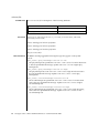
Below is a generic format for man pages. The man pages of each manual section
generally follow this order, but include only needed headings. For example, if there
are no bugs to report, there is no BUGS section. See the intro pages for more
information and detail about each section, and man(1) for more information about man
pages in general.
NAME
This section gives the names of the commands or
functions documented, followed by a brief
description of what they do.
SYNOPSIS
This section shows the syntax of commands or
functions. When a command or file does not exist
in the standard path, its full path name is shown.
Options and arguments are alphabetized, with
single letter arguments first, and options with
arguments next, unless a different argument order
is required.
The following special characters are used in this
section:
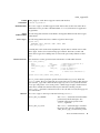
12
[ ]
Brackets. The option or argument
enclosed in these brackets is optional. If
the brackets are omitted, the argument
must be specified.
. . .
Ellipses. Several values can be provided
for the previous argument, or the
previous argument can be specified
multiple times, for example, "filename
. . ." .
|
Separator. Only one of the arguments
separated by this character can be
specified at a time.
{ }
Braces. The options and/or arguments
enclosed within braces are
interdependent, such that everything
enclosed must be treated as a unit.
man pages section 7: Device and Network Interfaces • December 2003
PROTOCOL
This section occurs only in subsection 3R to
indicate the protocol description file.
DESCRIPTION
This section defines the functionality and behavior
of the service. Thus it describes concisely what the
command does. It does not discuss OPTIONS or
cite EXAMPLES. Interactive commands,
subcommands, requests, macros, and functions are
described under USAGE.
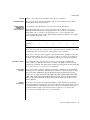
IOCTL
This section appears on pages in Section 7 only.
Only the device class that supplies appropriate
parameters to the ioctl(2) system call is called
ioctl and generates its own heading. ioctl calls
for a specific device are listed alphabetically (on the
man page for that specific device). ioctl calls are
used for a particular class of devices all of which
have an io ending, such as mtio(7I).
OPTIONS
This secton lists the command options with a
concise summary of what each option does. The
options are listed literally and in the order they
appear in the SYNOPSIS section. Possible
arguments to options are discussed under the
option, and where appropriate, default values are
supplied.
OPERANDS
This section lists the command operands and
describes how they affect the actions of the
command.
OUTPUT
This section describes the output – standard output,
standard error, or output files – generated by the
command.
RETURN VALUES
If the man page documents functions that return
values, this section lists these values and describes
the conditions under which they are returned. If a
function can return only constant values, such as 0
or –1, these values are listed in tagged paragraphs.
Otherwise, a single paragraph describes the return
values of each function. Functions declared void do
not return values, so they are not discussed in
RETURN VALUES.
ERRORS
On failure, most functions place an error code in
the global variable errno indicating why they
failed. This section lists alphabetically all error
codes a function can generate and describes the
conditions that cause each error. When more than
Preface
13
one condition can cause the same error, each
condition is described in a separate paragraph
under the error code.
USAGE
This section lists special rules, features, and
commands that require in-depth explanations. The
subsections listed here are used to explain built-in
functionality:
Commands
Modifiers
Variables
Expressions
Input Grammar
14
EXAMPLES
This section provides examples of usage or of how
to use a command or function. Wherever possible a
complete example including command-line entry
and machine response is shown. Whenever an
example is given, the prompt is shown as
example%, or if the user must be superuser,
example#. Examples are followed by explanations,
variable substitution rules, or returned values. Most
examples illustrate concepts from the SYNOPSIS,
DESCRIPTION, OPTIONS, and USAGE sections.
ENVIRONMENT VARIABLES
This section lists any environment variables that
the command or function affects, followed by a
brief description of the effect.
EXIT STATUS
This section lists the values the command returns to
the calling program or shell and the conditions that
cause these values to be returned. Usually, zero is
returned for successful completion, and values
other than zero for various error conditions.
FILES
This section lists all file names referred to by the
man page, files of interest, and files created or
required by commands. Each is followed by a
descriptive summary or explanation.
ATTRIBUTES
This section lists characteristics of commands,
utilities, and device drivers by defining the
attribute type and its corresponding value. See
attributes(5) for more information.
SEE ALSO
This section lists references to other man pages,
in-house documentation, and outside publications.
man pages section 7: Device and Network Interfaces • December 2003
DIAGNOSTICS
This section lists diagnostic messages with a brief
explanation of the condition causing the error.
WARNINGS
This section lists warnings about special conditions
which could seriously affect your working
conditions. This is not a list of diagnostics.
NOTES
This section lists additional information that does
not belong anywhere else on the page. It takes the
form of an aside to the user, covering points of
special interest. Critical information is never
covered here.
BUGS
This section describes known bugs and, wherever
possible, suggests workarounds.
Preface
15
16
man pages section 7: Device and Network Interfaces • December 2003
Introduction
17
Intro(7)
NAME
DESCRIPTION
Intro – introduction to special files
This section describes various device and network interfaces available on the system.
The types of interfaces described include character and block devices, STREAMS
modules, network protocols, file systems, and ioctl requests for driver subsystems and
classes.
This section contains the following major collections:
(7D)
The system provides drivers for a variety of hardware devices, such as
disk, magnetic tapes, serial communication lines, mice, and frame buffers,
as well as virtual devices such as pseudo-terminals and windows.
This section describes special files that refer to specific hardware
peripherals and device drivers. STREAMS device drivers are also
described. Characteristics of both the hardware device and the
corresponding device driver are discussed where applicable.
An application accesses a device through that device’s special file. This
section specifies the device special file to be used to access the device as
well as application programming interface (API) information relevant to
the use of the device driver.
All device special files are located under the /devices directory. The
/devices directory hierarchy attempts to mirror the hierarchy of system
busses, controllers, and devices configured on the system. Logical device
names for special files in /devices are located under the /dev directory.
Although not every special file under /devices will have a corresponding
logical entry under /dev, whenever possible, an application should
reference a device using the logical name for the device. Logical device
names are listed in the FILES section of the page for the device in
question.
This section also describes driver configuration where applicable. Many
device drivers have a driver configuration file of the form
driver_name.conf associated with them (see driver.conf(4)). The
configuration information stored in the driver configuration file is used to
configure the driver and the device. Driver configuration files are located in
/kernel/drv and /usr/kernel/drv. Driver configuration files for
platform dependent drivers are located in /platform/‘uname
-i‘/kernel/drv where ‘uname -i‘ is the output of the uname(1)
command with the -i option.
Some driver configuration files may contain user configurable properties.
Changes in a driver’s configuration file will not take effect until the system
is rebooted or the driver has been removed and re-added (see
rem_drv(1M) and add_drv(1M)).
(7FS)
18
This section describes the programmatic interface for several file systems
supported by SunOS.
man pages section 7: Device and Network Interfaces • Last Revised 29 Sep 1994
Intro(7)
(7I)
This section describes ioctl requests which apply to a class of drivers or
subsystems. For example, ioctl requests which apply to most tape devices
are discussed in mtio(7I). Ioctl requests relevant to only a specific device
are described on the man page for that device. The page for the device in
question should still be examined for exceptions to the ioctls listed in
section 7I.
(7M)
This section describes STREAMS modules. Note that STREAMS drivers are
discussed in section 7D. streamio(7I) contains a list of ioctl requests used
to manipulate STREAMS modules and interface with the STREAMS
framework. Ioctl requests specific to a STREAMS module will be discussed
on the man page for that module.
(7P)
This section describes various network protocols available in SunOS.
SunOS supports both socket-based and STREAMS-based network
communications. The Internet protocol family, described in inet(7P), is the
primary protocol family supported by SunOS, although the system can
support a number of others. The raw interface provides low-level services,
such as packet fragmentation and reassembly, routing, addressing, and
basic transport for socket-based implementations. Facilities for
communicating using an Internet-family protocol are generally accessed by
specifying the AF_INET address family when binding a socket; see
socket(3SOCKET) for details.
Major protocols in the Internet family include:
■
■
■
■
■
SEE ALSO
The Internet Protocol (IP) itself, which supports the universal datagram
format, as described in ip(7P). This is the default protocol for
SOCK_RAW type sockets within the AF_INET domain.
The Transmission Control Protocol (TCP); see tcp(7P). This is the
default protocol for SOCK_STREAM type sockets.
The User Datagram Protocol (UDP); see udp(7P). This is the default
protocol for SOCK_DGRAM type sockets.
The Address Resolution Protocol (ARP); see arp(7P).
The Internet Control Message Protocol (ICMP); see icmp(7P).
add_drv(1M), rem_drv(1M), intro(3), ioctl(2), socket(3SOCKET),
driver.conf(4), arp(7P), icmp(7P), inet(7P), ip(7P), mtio(7I), st(7D),
streamio(7I), tcp(7P), udp(7P)
System Administration Guide: IP Services
STREAMS Programming Guide
Writing Device Drivers
Introduction
19
Intro(7)
20
man pages section 7: Device and Network Interfaces • Last Revised 29 Sep 1994
Device and Network Interfaces
21
adp(7D)
NAME
DESCRIPTION
adp – Low-level module for controllers based on Adaptec AIC-7870P and AIC-7880P
SCSI chips
The adp module provides low-level interface routines between the common disk/tape
I/O system and SCSI (Small Computer System Interface) controllers based on the
Adaptec AIC-7870P and AIC-7880P SCSI chips. These controllers include the Adaptec
AHA–2940, AHA–2940W, AHA–2940U, AHA–2940UW, AHA–3940, and AHA–3940W,
as well as motherboards with embedded AIC-7870P and AIC-7880P SCSI chips.
Supported devices are AIC-7850, AIC-7860, AIC-7870, AIC-7880 and AIC-7895.
The adp module can be configured for disk and streaming tape support for one or
more host adapter boards, each of which must be the sole initiator on a SCSI bus.
Auto-configuration code determines if the adapter is present at the configured address
and what types of devices are attached to the adapter.
PRECONFIGURATION
The Plug N Play SCAM Support option is not supported.
Known Problems
and Limitations
■
To use the AHA-3940 or AHA-3940W adapters, the motherboard must have a BIOS
that supports the DEC PCI-to-PCI Bridge chip on the host bus adapter.
■
User-level programs have exhibited problems on some PCI systems with an
Adaptec AHA-2940 or AHA-2940W card and certain motherboards. If problems
with user-level programs occur, use the BIOS setup to disable write-back CPU
caching (or all caching if there is no control over the caching algorithm). The
affected motherboards are:
- PCI motherboards with a 60-MHz Pentium chip, with PCI chipset numbers S82433LX
Z852 and S82434LX Z850. The part numbers of the Intel motherboards are
AA616393-007 and AA615988-009.
- PCI motherboards with a 90-MHz Pentium chip, with PCI chipset numbers
S82433NX Z895, S82434NX Z895, and S82434NX Z896. The part number of the Intel
motherboard is 541286-005. (Some Gateway 2000 systems use this motherboard.)
- AA-619772-002 motherboard with 82433LX Z852 and 82434LX Z882 chips causes
random memory inconsistencies. Return the motherboard to the vendor for a
replacement.
CONFIGURATION
■
If the AHA-2940 SCSI adapter does not recognize the Quantum Empire 1080S, HP
3323 SE or other SCSI disk drive, reduce the Synchronous Transfer rate on the
Adaptec controller to 8 Mbps.
■
The AHA-3940 has been certified by Adaptec to work on specific systems; however,
some testing has shown that the Solaris operating environment works properly in
some of those systems and not in others.
Use the Adaptec configuration utility to perform the following steps:
■
22
Configure each SCSI device to have a unique SCSI ID, then using the adapter’s
Advanced Configuration Options setup menu, set the Plug N Play SCAM Support
option to Disabled.
man pages section 7: Device and Network Interfaces • Last Revised 10 Oct 2000
adp(7D)
FILES
ATTRIBUTES
■
If there is more than one controller (or an embedded controller), try to use one IRQ
per controller.
■
Enable bus mastering for the slots with your host bus adapters, when the choice is
given.
■
For older disk drives, tape drives, and most CD-ROM devices, make sure the
maximum SCSI data transfer speed is set to 5.0 Mbps.
■
Enable support for disks larger than 1 Gbyte if applicable.
/kernel/drv/adp.conf
Configuration file for the adp driver; there are no
user-configurable options in this file
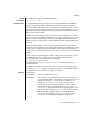
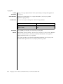
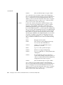
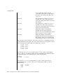
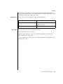
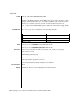
See attributes(5) for descriptions of the following attributes:
ATTRIBUTE TYPE
Architecture
SEE ALSO
ATTRIBUTE VALUE
x86
attributes(5)
Solaris (Intel Platform Edition) Hardware Compatibility List
NOTES
Throughout the release, support of additional devices may be added. See the Solaris
(Intel Platform Edition) Hardware Compatibility List for additional information.
The adp driver supports Logical Unit Number (“LUN”) values of 0 through 15. This
range exceeds the standard SCSI-2 requirements which call for support of LUNs 0
through 7.
Device and Network Interfaces
23
adpu320(7D)
NAME
SYNOPSIS
DESCRIPTION
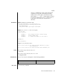
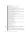
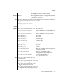
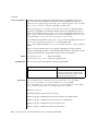
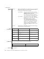
adpu320 – Adaptec Ultra320 SCSI host bus adapter driver
scsi@unit-address
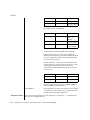
The adpu320 host bus adapter driver is a SCSA-compliant nexus driver that supports
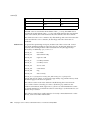
the following Adaptec Ultra320 SCSI Devices:
Chips
AIC-7902
The adpu320 driver supports standard functions provided by the SCSA interface,
including tagged and untagged queuing, Wide/Fast/Ultra SCSI, and auto request
sense. The adpu320 driver does not support linked commands. The adpu320 driver
supports hot swap SCSI and hot plug PCI.
Additionally, the adpu320 driver supports the following features:
■
■
■
■
■
■
■
■
■
■
Driver
Configuration
64-bit addressing (Dual address Cycle)
PCI-X v1.1 operating up to 133MHz and 64bits
PCI bus spec v2.2 operating up to 66MHz and 64bits
Packetized SCSI at 320 and 160 MB/s
QAS
DT
40MB/sec in single-ended mode and up to 320MB/sec transfer rate in LVD mode
Domain Validation
Retained Training Information (RTI)
PCI and PCI-X Error handling
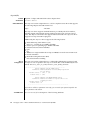
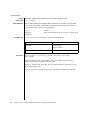
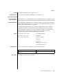
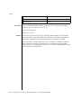
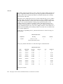
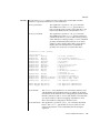
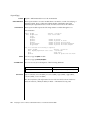
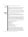
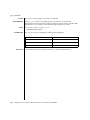
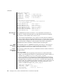
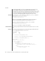
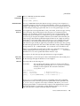
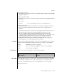
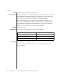
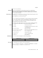
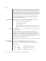
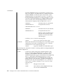
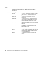
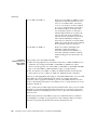
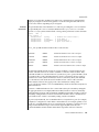
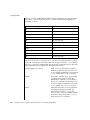
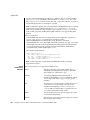
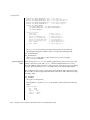
The adpu320 host bus adapter driver is configured by defining the properties found
in adpu320.conf. Properties in the adpu320.conf file that can be modified by the user
include: ADPU320_SCSI_RD_STRM, ADPU320_SCSI_NLUN_SUPPORT.
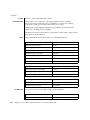
------------------------------------------------------------Option: ADPU320_SCSI_RD_STRM=[value]
Definition: Enables/disables read streaming negotiation
for all drives.
Possible Values: 0 (off), 1 (on)
Default Value: 0 (off)
Option: ADPU320_SCSI_NLUN_SUPPORT=[value]
Definition: Enables the number of logical units to be
scanned per drive.
Possible Values: 1-64
Default Value: 64
-------------------------------------------------------------
If you alter or add driver parameters incorrectly, you can render your system inoperable. Use
driver parameters with caution.
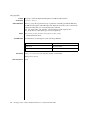
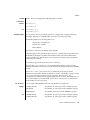
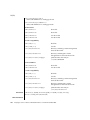
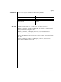
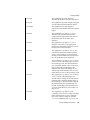
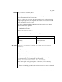
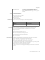
ATTRIBUTES
24
See attributes(5) for descriptions of the following attributes:
man pages section 7: Device and Network Interfaces • Last Revised 22 Apr 2003
adpu320(7D)
ATTRIBUTE TYPE
Availability
FILES
ATTRIBUTE VALUE
x86
/kernel/drv/adpu320
Driver model
/kernel/drv/adpu320.conf
Configuration file
/boot/solaris/drivers/notisa.010/adpu320.bef
Realmode driver
SEE ALSO
cfgadm(1M), prtconf(1M), attributes(5), scsi_abort(9F),
scsi_hba_attach(9F), scsi_ifgetcap(9F), scsi_reset(9F),
scsi_sync_pkt(9F), scsi_transport(9F), scsi_device(9S),
scsi_extended_sense(9S), scsi_inquiry(9S), scsi_pkt(9S)
Writing Device Drivers
Small Computer System Interface-3 (SCSI-3)
Device and Network Interfaces
25
afb(7d)
NAME
DESCRIPTION
FILES
afb – Elite3D graphics accelerator driver
The afb driver is the device driver for the Sun Elite3D graphics accelerators. The
afbdaemonprocess loads the afb microcode at system startup time and during the
resume sequence of a suspend-resume cycle.
/dev/fbs/afbn
Device special file
/usr/lib/afb.ucode
afb microcode
/usr/sbin/afbdaemon
afb microcode loader
SEE ALSO
26
afbconfig(1M)
man pages section 7: Device and Network Interfaces • Last Revised 27 Aug 1999
arp(7P)
NAME
SYNOPSIS
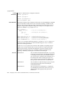
arp, ARP – Address Resolution Protocol
#include <sys/fcntl.h>
#include <sys/socket.h>
#include <net/if_arp.h>
#include <netinet/in.h>
s = socket(AF_INET, SOCK_DGRAM, 0);
d = open ("/dev/arp", oflag);
DESCRIPTION
ARP is a protocol used to map dynamically between Internet Protocol (IP) and
10Mb/s Ethernet addresses. It is used by all the 10Mb/s Ethernet datalink providers
(interface drivers) and it can be used by other datalink providers that support
broadcast, such as FDDI and Token Ring. The only network layer supported in this
implementation is the Internet Protocol, although ARP is not specific to that protocol.
ARP caches IP-to-Ethernet address mappings. When an interface requests a mapping
for an address not in the cache, ARP queues the message that requires the mapping
and broadcasts a message on the associated network requesting the address mapping.
If a response is provided, ARP caches the new mapping and transmits any pending
message. ARP will queue at most four packets while waiting for a response to a
mapping request; it keeps only the four most recently transmitted packets.
APPLICATION
PROGRAMMING
INTERFACE
The STREAMS device /dev/arp is not a Transport Level Interface (“TLI)” transport
provider and may not be used with the TLI interface.
To facilitate communications with systems that do not use ARP, ioctl() requests are
provided to enter and delete entries in the IP-to-Ethernet tables.
#include <sys/sockio.h>
#include <sys/socket.h>
#include <net/if.h>
#include <net/if_arp.h>
struct arpreq arpreq;
ioctl(s, SIOCSARP, (caddr_t)&arpreq);
ioctl(s, SIOCGARP, (caddr_t)&arpreq);
ioctl(s, SIOCDARP, (caddr_t)&arpreq);
Each ioctl() request takes the same structure as an argument. SIOCSARP sets an
ARP entry, SIOCGARP gets an ARP entry, and SIOCDARP deletes an ARP entry. These
ioctl() requests may be applied to any Internet family socket descriptor s, or to a
descriptor for the ARP device, but only by the privileged user.
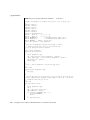
The arpreq structure contains:
/*
* ARP ioctl request
*/
struct arpreq {
struct sockaddr arp_pa;
/* protocol address */
Device and Network Interfaces
27
arp(7P)
struct sockaddr arp_ha;
int arp_flags;
/* hardware address */
/* flags */
};
#define
#define
#define
#define
ATF_COM 0x2
ATF_PERM 0x4
ATF_PUBL 0x8
ATF_USETRAILERS 0x10
/*
/*
/*
/*
/*
arp_flags field values
*/
completed entry (arp_ha valid) */
permanent entry */
publish (respond for other host) */
send trailer packets to host */
The address family for the arp_pa sockaddr must be AF_INET; for the arp_ha
sockaddr, it must be AF_UNSPEC. The only flag bits that may be written are
ATF_PUBL and ATF_USETRAILERS. ATF_PERM makes the entry permanent if the
ioctl() request succeeds. The peculiar nature of the ARP tables may cause the
ioctl() request to fail if too many permanent IP addresses hash to the same slot.
ATF_PUBL specifies that the ARP code should respond to ARP requests for the
indicated host coming from other machines. This allows a host to act as an “ARP
server”, which may be useful in convincing an ARP-only machine to talk to a
non-ARP machine.
ARP is also used to negotiate the use of trailer IP encapsulations. Trailers are an
alternate encapsulation used to allow efficient packet alignment for large packets
despite variable-sized headers. Hosts that wish to receive trailer encapsulations so
indicate by sending gratuitous ARP translation replies along with replies to IP
requests; trailer encapsulations are also sent in reply to IP translation replies. The
negotiation is thus fully symmetrical, in that either host or both may request trailers.
The ATF_USETRAILERS flag records the receipt of such a reply and enables the
transmission of trailer packets to that host.
ARP watches passively for hosts impersonating the local host (that is, a host which
responds to an ARP mapping request for the local host’s address).
SEE ALSO
arp(1M), ifconfig(1M), if_tcp(7P), inet(7P)
Leffler, Sam, and Michael Karels, Trailer Encapsulations, RFC 893, Network Information
Center, SRI International, Menlo Park, California, April 1984.
Plummer, Dave, An Ethernet Address Resolution Protocol -or- Converting Network Protocol
Addresses to 48.bit Ethernet Addresses for Transmission on Ethernet Hardware, RFC 826,
Network Information Center, SRI International, Menlo Park, California, November
1982.
DIAGNOSTICS
IP: Hardware address ’%x:%x:%x:%x:%x:%x’
trying to be our address ’%d.%d.%d.%d’!
Duplicate IP address. ARP has discovered another host on the local network which
responds to mapping requests for the Internet address of this system.
IP: Proxy ARP problem? Hardware address ’%x:%x:%x:%x:%x:%x’
thinks it is ’%d.%d.%d.%d’
This message will appear if arp(1M) has been used to create a published entry, and
some other host on the local network responds to mapping requests for the
published ARPentry.
28
man pages section 7: Device and Network Interfaces • Last Revised 23 Aug 1994
asy(7D)
NAME
SYNOPSIS
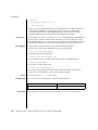
asy – asynchronous serial port driver
#include <fcntl.h>
#include <sys/termios.h>
open("/dev/term/n", mode);
open("/dev/tty/n", mode);
open("/dev/cua/n", mode);
DESCRIPTION
The asy module is a loadable STREAMS driver that provides basic support for the
standard UARTS that use Intel-8250, National Semiconductor-16450 and 16550
hardware, in addition to basic asynchronous communication support. The asy
module supports those termio(7I) device control functions specified by flags in the
c_cflag word of the termios structure, and by the IGNBRK, IGNPAR, PARMRK, or
INPCK flags in the c_iflag word of the termios structure. All other termio(7I)
functions must be performed by STREAMS modules pushed atop the driver. When a
device is opened, the ldterm(7M) and ttcompat(7M) STREAMS modules are
automatically pushed on top of the stream, providing the standard termio(7I)
interface.
The character-special devices /dev/term/a and /dev/term/b are used to access the
two standard serial ports (COM1 and COM2) on an x86 system. The asy module
supports up to four serial ports, including the standard ports. Device names are
typically used to provide a logical access point for a dial-in line that is used with a
modem.
To allow a single tty line to be connected to a modem and used for incoming and
outgoing calls, a special feature is available that is controlled by the minor device
number. By accessing character-special devices with names of the form /dev/cua/n,
it is possible to open a port without the Carrier Detect signal being asserted,
either through hardware or an equivalent software mechanism. These devices are
commonly known as dial-out lines.
Note – This module is affected by the setting of certain eeprom variables. For
information on parameters that are persistent across reboots, see the eeprom(1M) man
page.
Note – In Solaris 8 and later versions, the default setting for ttya-ignore-cd and
ttya-trs-dtr-off is true. To avoid having their modems fail, users of Solaris 7
(and earlier versions) should change the settings of ttya-ignore-cd and
ttya-trs-dtr-off to false.
APPLICATION
PROGRAMMING
INTERFACE
Once a /dev/cua/n line is opened, the corresponding tty line cannot be opened until
the /dev/cua/n line is closed. A blocking open will wait until the /dev/cua/n line
is closed (which will drop Data Terminal Ready, after which Carrier Detect
will usually drop as well) and carrier is detected again. A non-blocking open will
return an error. If the /dev/ttydn line has been opened successfully (usually only
when carrier is recognized on the modem), the corresponding /dev/cua/n line
Device and Network Interfaces
29
asy(7D)
cannot be opened. This allows a modem to be attached to /dev/term/[n] (renamed
from /dev/tty[n]) and used for dial-in (by enabling the line for login in
/etc/inittab) or dial-out (by tip(1) or uucp(1C)) as /dev/cua/n when no one is
logged in on the line.
IOCTLS
The standard set of termio ioctl() calls are supported by asy.
Breaks can be generated by the TCSBRK, TIOCSBRK, and TIOCCBRK ioctl() calls.
The input and output line speeds may be set to any speed that is supported by
termio. The speeds cannot be set independently; for example, when the output speed
is set, the input speed is automatically set to the same speed.
When the asy module is used to service the serial console port, it supports a BREAK
condition that allows the system to enter the debugger or the monitor. The BREAK
condition is generated by hardware and it is usually enabled by default.
A BREAK condition originating from erroneous electrical signals cannot be
distinguished from one deliberately sent by remote DCE. The Alternate Break
sequence can be used as a remedy against this. Due to a risk of incorrect sequence
interpretation, SLIP and certain other binary protocols should not be run over the
serial console port when Alternate Break sequence is in effect. Although PPP is a
binary protocol, it is able to avoid these sequences using the ACCM feature in RFC
1662. For Solaris PPP 4.0, you do this by adding the following line to the
/etc/ppp/options file (or other configuration files used for the connection; see
pppd(1M) for details):
asyncmap
0x00002000
By default, the Alternate Break sequence is a three character sequence: carriage return,
tilde and control-B (CR ~ CTRL-B), but may be changed by the driver. For more
information on breaking (entering the debugger or monitor), see kbd(1) and kb(7M).
ERRORS
FILES
An open() will fail under the following conditions:
ENXIO
The unit being opened does not exist.
EBUSY
The dial-out device is being opened while the dial-in device is
already open, or the dial-in device is being opened with a no-delay
open and the dial-out device is already open.
EBUSY
The unit has been marked as exclusive-use by another process
with a TIOCEXCL ioctl() call.
EINTR
The open was interrupted by the delivery of a signal.
/dev/term/[a-z]
dial-in tty lines
/dev/cua/[a-z]
dial-out tty lines
/platform/i86pc/kernel/drv/asy.conf
asy configuration file
30
man pages section 7: Device and Network Interfaces • Last Revised 9 Sep 2002
asy(7D)
ATTRIBUTES
See attributes(5) for descriptions of the following attributes:
ATTRIBUTE TYPE
Architecture
SEE ALSO
DIAGNOSTICS
ATTRIBUTE VALUE
x86
tip(1), kbd(1), uucp(1C), eeprom(1M), pppd(1M), ioctl(2), open(2), termios(3C),
attributes(5), ldterm(7M), ttcompat(7M), kb(7M), termio(7I)
asyn : silo overflow.
The hardware overrun occurred before the input character could be serviced.
asyn : ring buffer overflow.
The driver’s character input ring buffer overflowed before it could be serviced.
Device and Network Interfaces
31
ata(7D)
NAME
SYNOPSIS
ata – AT attachment disk driver
ata@1,ioaddr
DESCRIPTION
The ata driver supports disk and CD-ROM interfaces conforming to the AT
Attachment specification including IDE interfaces. It excludes the MFM, RLL, ST506,
and ST412 interfaces. Support is provided for CD_ROM drives that conform to the
Small Form Factor (SFF) ATA Packet Interface (ATAPI) specification: SFF-8020 revision
1.2.
PRECONFIGURE
If two IDE drives share the same controller, you must set one to master and the other to
slave. If both an IDE disk drive and an IDE CD-ROM drive utilize the same controller,
you can designate the disk drive as the master with the CD-ROM drive as the slave,
although this is not mandatory. If there is only one drive on a controller, it must be set
to master.
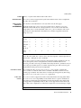
Supported Settings
Primary controller:
■
■
IRQ Level: 14
I/O Address: 0x1F0
Secondary controller:
■
■
IRQ Level: 15
I/O Address: 0x170
If an IDE CD-ROM drive is installed, the system BIOS parameter for that device
should be:
■
Drive Type: Not installed
If an enhanced IDE drive is installed, set the system BIOS as follows:
■
Enhanced IDE Drive: Enabled
Note – If the BIOS supports autoconfiguration, use this facility to set the number of
heads, cylinders, and sectors for the IDE disk drive. If this capability is not supported
by the BIOS, use the settings provided by the disk manufacturer.
Known Problems
and Limitations
32
■
Panasonic LK-MC579B and the Mitsumi FX34005 IDE CD-ROM drives cannot be
used to install the Solaris operating environment and are not supported.
■
Some vendors ship PCI-equipped machines with IDE interfaces on the
motherboard. A number of these machines use the CMD-604 PCI-IDE controller.
This chip provides two IDE interfaces. The primary IDE interface is at I/O address
0x1F0 and the secondary interface at 0x170. However, this chip cannot handle
simultaneous I/O on both IDE interfaces. This defect causes the Solaris software to
hang if both interfaces are used. Use only the primary IDE interface at address
0x1F0.
■
You cannot boot from the third or fourth IDE disk drives; however you can install
Solaris software on them.
man pages section 7: Device and Network Interfaces • Last Revised 21 Aug 2001
ata(7D)
■
The Solaris Volume Management software does not work with the Sony CDU-55E
CD-ROM drive no matter how it is configured (as the master or the slave).
Comment out the following line in the file /etc/vold.conf to prevent vold from
hanging the controller:
# use cdrom drive /dev/rdsk/c*s2 dev_cdrom.so cdrom%d
Direct Memory
Access (DMA) and
PCI-IDE Systems
■
NEC CDR-260/CDR-260R/CDR-273 and Sony CDU-55E ATAPI CD-ROM drives
might fail during installation.
■
Sony CDU-701 CD-ROM drives must be upgraded to use firmware version 1.0r or
later to support booting from the CD.
Direct Memory Access is enabled by default. To disable DMA for the ata driver, do
the following steps after you have installed the Solaris operating environment:
1. Run the Solaris (x86 Edition) Device Configuration Assistant from the boot diskette
or the installation CD (if your system supports CD-ROM booting).
Note – After you boot using the boot diskette, the new ata-dma-enabled
property value is preserved on the diskette. This means that the changed value is
in effect each time you use the boot diskette.
2. Press F2_Continue to scan for devices.
3. Press F2_Continue to display a list of boot devices on the Boot Solaris menu.
4. Go to the View/Edit Property Settings menu.
5. Press F4_Boot Tasks, select View/Edit Property Settings, and press
F2_Continue.
6. Change the value of the ata-dma-enabled property. A value of 1 indicates that
DMA is enabled and 0 indicates that DMA is disabled.
CONFIGURATION
■
Select the ata-dma-disabled property from the list and press F3_Change.
■
Type 0 and press F2_Continue to disable DMA.
■
Press F2_Back to return to the Boot Tasks menu.
■
Press F3_Back to return to the Boot Solaris menu.
■
Select the device from which you want to install (network adapter or CD-ROM
drive) and press F2_Continue.
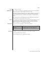
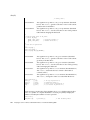
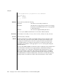
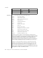
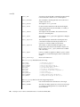
The driver initializes itself in accordance with the information found in the
configuration file ata.conf (see below). The only user configurable items in this file
are:
drive0_block_factor
drive1_block_factor
ATA controllers support some amount of buffering
(blocking). The purpose is to interrupt the host when
an entire buffer full of data has been read or written
instead of using an interrupt for each sector. This
reduces interrupt overhead and significantly increases
throughput. The driver interrogates the controller to
find the buffer size. Some controllers hang when
Device and Network Interfaces
33
ata(7D)
buffering is used, so the values in the configuration file
are used by the driver to reduce the effect of buffering
(blocking). The values presented may be chosen from
0x1, 0x2, 0x4, 0x8 and 0x10.
The values as shipped are set to 0x1, and they can be
tuned to increase performance.
If your controller hangs when attempting to use higher
block factors, you may be unable to reboot the system.
For x86 based systems, it is recommended that the
tuning be carried out using a duplicate of the
/platform/i86pc/kernel directory subtree. This
will ensure that a bootable kernel subtree exists in the
event of a failed test.
max_transfer
ata-revert-todefaults
revert—<diskmodel>
This value controls the size of individual requests for
consecutive disk sectors. The value may range from
0x1 to 0x100. Higher values yield higher throughput.
The system is shipped with a value of 0x100, which
should not be changed.
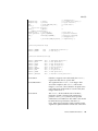
When preparing to reboot (or shutdown), the ata
driver issues a command that allows the disk to revert
to power-on defaults when it receives a software reset
(SRST) sequence. This is usually appropriate as
preparation for the boot sequence. However, this
doesn’t work properly on certain combinations of disk
and system ROM (BIOS). Solaris maintains a list of
disks known to cause this problem; however the list is
not all-inclusive and other models may also be affected.
To disallow revert to power-on defaults for all ATA
disks, set ata-revert-to-defaults to 0.
To disallow revert to power-on defaults only for disks
of a particular model, set revert—<diskmodel> to 0.
Explicitly set ata-revert-to-defaults or
revert-<diskmodel> (x86 only) to 1 to override
Solaris’ built-in list and allow reverting to power-on
defaults for all disks or a particular model of disk.
To determine the string to substitute for
<diskmodel>, boot your system (you may have to
press the reset button or power-cycle) and then go to
/var/adm/messages. Look for the string "IDE device
34
man pages section 7: Device and Network Interfaces • Last Revised 21 Aug 2001
ata(7D)
at targ" or "ATAPI device at targ." The next line will
contain the word "model" followed by the model
number and a comma. Ignore all characters except
letters, digits, ".", "_", and "-". Change uppercase letters
to lower case. If the string revert-<diskmodel> is
longer than 31 characters, use only the first 31
characters.
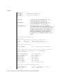
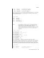
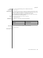
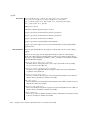
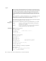
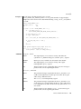
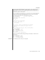
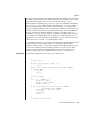
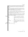
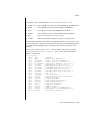
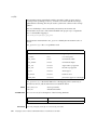
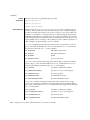
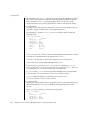
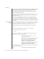
EXAMPLES
EXAMPLE 1
Sample ata Configuration File
# for higher performance - set block factor to 16
drive0_block_factor=0x1 drive1_block_factor=0x1
max_transfer=0x100
flow_control="dmult" queue="qsort" disk="dadk" ;
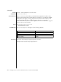
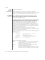
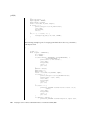
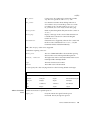
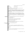
EXAMPLE 2 ata-revert-to-defaults Property
# tail ata.conf
# timer resolution.
#
#
standby=-1
#
standby=0
#
standby=n
#
don’t modify the drive’s current setting
disable standby timer
n == number of seconds to set the timer to
#standby=900;
revert-st320420a=0;
Output of /var/adm/messages:
Aug 17 06:49:43 caesar ata:[ID 640982 kern.info] IDE device at targ 0,
lun 0 lastlun 0x0
Aug 17 06:49:43 caesar ata:[ID 521533 kern.info] model ST320420A, stat
FILES
/platform/i86pc/kernel/drv/ata
Device file.
/platform/i86pc/kernel/drv/ata.conf
Configuration file.
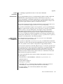
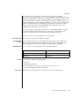
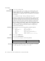
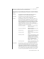
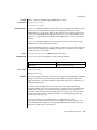
ATTRIBUTES
See attributes(5) for descriptions of the following attributes:
ATTRIBUTE TYPE
Architecture
SEE ALSO
ATTRIBUTE VALUE
x86
attributes(5), cmdk(7D)
Device and Network Interfaces
35
audio(7I)
NAME
SYNOPSIS
audio – generic audio device interface
#include <sys/audio.h>
OVERVIEW
An audio device is used to play and/or record a stream of audio data. Since a specific
audio device may not support all functionality described below, refer to the
device-specific manual pages for a complete description of each hardware device. An
application can use the AUDIO_GETDEV ioctl(2) to determine the current audio
hardware associated with /dev/audio.
AUDIO
FORMATS
Digital audio data represents a quantized approximation of an analog audio signal
waveform. In the simplest case, these quantized numbers represent the amplitude of
the input waveform at particular sampling intervals. To achieve the best
approximation of an input signal, the highest possible sampling frequency and
precision should be used. However, increased accuracy comes at a cost of increased
data storage requirements. For instance, one minute of monaural audio recorded in
µ-Law format (pronounced mew-law) at 8 KHz requires nearly 0.5 megabytes of
storage, while the standard Compact Disc audio format (stereo 16-bit linear PCM data
sampled at 44.1 KHz) requires approximately 10 megabytes per minute.
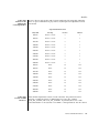
Audio data may be represented in several different formats. An audio device’s current
audio data format can be determined by using the AUDIO_GETINFO ioctl(2)
described below.
An audio data format is characterized in the audio driver by four parameters: Sample
Rate, Encoding, Precision, and Channels. Refer to the device-specific manual pages for
a list of the audio formats that each device supports. In addition to the formats that
the audio device supports directly, other formats provide higher data compression.
Applications may convert audio data to and from these formats when playing or
recording.
Sample Rate
Encodings
Sample rate is a number that represents the sampling frequency (in samples per
second) of the audio data.
An encoding parameter specifies the audio data representation. µ-Law encoding
corresponds to CCITT G.711, and is the standard for voice data used by telephone
companies in the United States, Canada, and Japan. A-Law encoding is also part of
CCITT G.711 and is the standard encoding for telephony elsewhere in the world.
A-Law and µ-Law audio data are sampled at a rate of 8000 samples per second with
12-bit precision, with the data compressed to 8-bit samples. The resulting audio data
quality is equivalent to that of standard analog telephone service.
Linear Pulse Code Modulation (PCM) is an uncompressed, signed audio format in
which sample values are directly proportional to audio signal voltages. Each sample is
a 2’s complement number that represents a positive or negative amplitude.
Precision
36
Precision indicates the number of bits used to store each audio sample. For instance,
u-Law and A-Law data are stored with 8-bit precision. PCM data may be stored at
various precisions, though 16-bit is the most common.
man pages section 7: Device and Network Interfaces • Last Revised 28 Dec 2001
audio(7I)
Channels
DESCRIPTION
Multiple channels of audio may be interleaved at sample boundaries. A sample frame
consists of a single sample from each active channel. For example, a sample frame of
stereo 16-bit PCM data consists of 2 16-bit samples, corresponding to the left and right
channel data.
The device /dev/audio is a device driver that dispatches audio requests to the
appropriate underlying audio hardware. The audio driver is implemented as a
STREAMS driver. In order to record audio input, applications open(2) the
/dev/audio device and read data from it using the read(2) system call. Similarly,
sound data is queued to the audio output port by using the write(2) system call.
Device configuration is performed using the ioctl(2) interface.
Alternatively, opening /dev/audio may open a mixing audio driver that provides a
super set of this audio interface. The audio mixer removes the exclusive resource
restriction, allowing multiple processes to play and record audio at the same time. See
the mixer(7I) and audio_support(7I) manual pages for more information.
Because some systems may contain more than one audio device, application writers
are encouraged to query the AUDIODEV environment variable. If this variable is
present in the environment, its value should identify the path name of the default
audio device.
Opening the
Audio Device
The audio device is treated as an exclusive resource, meaning that only one process
can open the device at a time. However, if the DUPLEX bit is set in the hw_features
field of the audio information structure, two processes may simultaneously access the
device. This allows one process to open the device as read-only and a second process
to open it as write-only. See below for details.
When a process cannot open /dev/audio because the device is busy:
■
if either the O_NDELAY or O_NONBLOCK flags are set in the open() oflag argument,
then –1 is immediately returned, with errno set to EBUSY.
■
if neither the O_NDELAY nor the O_NONBLOCK flag are set, then open() hangs
until the device is available or a signal is delivered to the process, in which case a
–1 is returned with errno set to EINTR. This allows a process to block in the open
call while waiting for the audio device to become available.
Upon the initial open() of the audio device, the driver resets the data format of the
device to the default state of 8-bit, 8Khz, mono u-Law data. If the device is already
open and a different audio format is set, this will not be possible on some devices.
Audio applications should explicitly set the encoding characteristics to match the
audio data requirements rather than depend on the default configuration.
Since the audio device grants exclusive read or write access to a single process at a
time, long-lived audio applications may choose to close the device when they enter an
idle state and reopen it when required. The play.waiting and record.waiting flags in the
audio information structure (see below) provide an indication that another process has
requested access to the device. For instance, a background audio output process may
choose to relinquish the audio device whenever another process requests write access.
Device and Network Interfaces
37
audio(7I)
Recording Audio
Data
The read() system call copies data from the system’s buffers to the application.
Ordinarily, read() blocks until the user buffer is filled. The I_NREAD ioctl (see
streamio(7I)) may be used to determine the amount of data that may be read
without blocking. The device may alternatively be set to a non-blocking mode, in
which case read() completes immediately, but may return fewer bytes than
requested. Refer to the read(2) manual page for a complete description of this
behavior.
When the audio device is opened with read access, the device driver immediately
starts buffering audio input data. Since this consumes system resources, processes that
do not record audio data should open the device write-only (O_WRONLY).
The transfer of input data to STREAMS buffers may be paused (or resumed) by using
the AUDIO_SETINFO ioctl to set (or clear) the record.pause flag in the audio
information structure (see below). All unread input data in the STREAMS queue may
be discarded by using the I_FLUSH STREAMS ioctl (see streamio(7I)). When
changing record parameters, the input stream should be paused and flushed before
the change, and resumed afterward. Otherwise, subsequent reads may return samples
in the old format followed by samples in the new format. This is particularly
important when new parameters result in a changed sample size.
Input data can accumulate in STREAMS buffers very quickly. At a minimum, it will
accumulate at 8000 bytes per second for 8-bit, 8 KHz, mono, u-Law data. If the device
is configured for 16-bit linear or higher sample rates, it will accumulate even faster. If
the application that consumes the data cannot keep up with this data rate, the
STREAMS queue may become full. When this occurs, the record.error flag is set in the
audio information structure and input sampling ceases until there is room in the input
queue for additional data. In such cases, the input data stream contains a
discontinuity. For this reason, audio recording applications should open the audio
device when they are prepared to begin reading data, rather than at the start of
extensive initialization.
Playing Audio
Data
The write() system call copies data from an application’s buffer to the STREAMS
output queue. Ordinarily, write() blocks until the entire user buffer is transferred.
The device may alternatively be set to a non-blocking mode, in which case write()
completes immediately, but may have transferred fewer bytes than requested (see
write(2)).
Although write() returns when the data is successfully queued, the actual
completion of audio output may take considerably longer. The AUDIO_DRAIN ioctl
may be issued to allow an application to block until all of the queued output data has
been played. Alternatively, a process may request asynchronous notification of output
completion by writing a zero-length buffer (end-of-file record) to the output stream.
When such a buffer has been processed, the play.eof flag in the audio information
structure (see below) is incremented.
38
man pages section 7: Device and Network Interfaces • Last Revised 28 Dec 2001
audio(7I)
The final close(2) of the file descriptor hangs until all of the audio output has
drained. If a signal interrupts the close(), or if the process exits without closing the
device, any remaining data queued for audio output is flushed and the device is
closed immediately.
The consumption of output data may be paused (or resumed) by using the
AUDIO_SETINFO ioctl to set (or clear) the play.pause flag in the audio information
structure. Queued output data may be discarded by using the I_FLUSH STREAMS
ioctl. (See streamio(7I)).
Output data is played from the STREAMS buffers at a default rate of at least 8000
bytes per second for µ-Law, A-Law or 8–bit PCM data (faster for 16-bit linear data or
higher sampling rates). If the output queue becomes empty, the play.error flag is set in
the audio information structure and output is stopped until additional data is written.
If an application attempts to write a number of bytes that is not a multiple of the
current sample frame size, an error is generated and the bad data is thrown away.
Additional writes are allowed.
Asynchronous I/O
The I_SETSIG STREAMS ioctl enables asynchronous notification, through the
SIGPOLL signal, of input and output ready condition changes. The O_NONBLOCK flag
may be set using the F_SETFL fcntl(2) to enable non-blocking read() and
write() requests. This is normally sufficient for applications to maintain an audio
stream in the background.
Audio Control
Pseudo-Device
It is sometimes convenient to have an application, such as a volume control panel,
modify certain characteristics of the audio device while it is being used by an
unrelated process. The /dev/audioctl pseudo-device is provided for this purpose.
Any number of processes may open /dev/audioctl simultaneously. However,
read() and write() system calls are ignored by /dev/audioctl. The
AUDIO_GETINFO and AUDIO_SETINFO ioctl commands may be issued to
/dev/audioctl to determine the status or alter the behavior of /dev/audio. Note:
In general, the audio control device name is constructed by appending the letters
"ctl" to the path name of the audio device.
Audio Status
Change
Notification
Applications that open the audio control pseudo-device may request asynchronous
notification of changes in the state of the audio device by setting the S_MSG flag in an
I_SETSIG STREAMS ioctl. Such processes receive a SIGPOLL signal when any of
the following events occur:
■
An AUDIO_SETINFO ioctl has altered the device state.
■
An input overflow or output underflow has occurred.
■
An end-of-file record (zero-length buffer) has been processed on output.
■
An open() or close() of /dev/audio has altered the device state.
■
An external event (such as speakerbox’s volume control) has altered the device
state.
IOCTLS
Device and Network Interfaces
39
audio(7I)
Audio Information
Structure
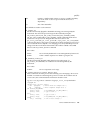
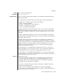
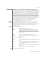
The state of the audio device may be polled or modified using the AUDIO_GETINFO
and AUDIO_SETINFO ioctl commands. These commands operate on the
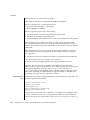
audio_info structure as defined, in <sys/audioio.h>, as follows:
/*
* This structure contains state information for audio device
* IO streams
*/
struct audio_prinfo {
/*
* The following values describe the
* audio data encoding
*/
uint_t sample_rate; /* samples per second */
uint_t channels;
/* number of interleaved channels */
uint_t precision;
/* number of bits per sample */
uint_t encoding;
/* data encoding method */
/*
* The following values control audio device
* configuration
*/
uint_t
gain;
/* volume level */
uint_t
port;
/* selected I/O port */
uint_t
buffer_size; /* I/O buffer size */
/*
* The following values describe the current device
* state
*/
uint_t
samples;
/* number of samples converted */
uint_t
eof;
/* End Of File counter (play only) */
uchar_t
pause;
/* non-zero if paused, zero to resume */
uchar_t
error;
/* non-zero if overflow/underflow */
uchar_t
waiting; /* non-zero if a process wants access */
uchar_t
balance;
/* stereo channel balance */
/*
* The following values are read-only device state
* information
*/
uchar_t open;
/* non-zero if open access granted */
uchar_t
active;
/* non-zero if I/O active */
uint_t
avail_ports; /* available I/O ports */
uint_t
mod_ports;
/* modifiable I/O ports */
};
typedef struct audio_prinfo audioi_prinfo_t;
/*
* This structure is used in AUDIO_GETINFO and AUDIO_SETINFO ioctl
* commands
*/
struct audio_info {
audio_prinfo_t record;
/* input status info */
audio_prinfo_t play;
/* output status info */
uint_t
monitor_gain; /* input to output mix */
uchar_t
output_muted; /* non-zero if output muted */
uint_t
hw_features;
/* supported H/W features */
40
man pages section 7: Device and Network Interfaces • Last Revised 28 Dec 2001
audio(7I)
uint_t
uint_t
sw_features; /* supported S/W features */
sw_features_enabled;
/* supported S/W features enabled */
};
typedef struct audio_info
audio_info_t;
/* Audio encoding types */
#define AUDIO_ENCODING_ULAW
(1) /* u-Law encoding */
#define AUDIO_ENCODING_ALAW
(2) /* A-Law encoding */
#define AUDIO_ENCODING_LINEAR
(3) /* Signed Linear PCM encoding */
/*
* These ranges apply to record, play, and
* monitor gain values
*/
#define AUDIO_MIN_GAIN (0)
/* minimum gain value */
#define AUDIO_MAX_GAIN (255) /* maximum gain value */
/*
* These values apply to the balance field to adjust channel
* gain values
*/
#define AUDIO_LEFT_BALANCE
(0)
/* left channel only */
#define AUDIO_MID_BALANCE (32)
/* equal left/right balance */
#define AUDIO_RIGHT_BALANCE (64)
/* right channel only */
/*
* Define some convenient audio port names
* (for port, avail_ports and mod_ports)
*/
/* output ports (several might be enabled at once) */
#define AUDIO_SPEAKER
(0x01)
/* built-in speaker */
#define AUDIO_HEADPHONE (0x02)
/* headphone jack */
#define AUDIO_LINE_OUT (0x04)
/* line out */
#define AUDIO_SPDIF_OUT (0x08)
/* SPDIF port */
#define AUDIO_AUX1_OUT (0x10)
/* aux1 out */
#define AUDIO_AUX2_OUT (0x20)
/* aux2 out */
/* input ports (usually only
* enabled at a time)
*/
#define AUDIO_MICROPHONE
#define AUDIO_LINE_IN
#define AUDIO_CD
#define AUDIO_SPDIF_IN
#define AUDIO_AUX1_IN
#define AUDIO_AUX2_IN
#define AUDIO_CODEC_LOOPB_IN
one may be
(0x01) /* microphone */
(0x02) /* line in */
(0x04) /* on-board CD inputs */
(0x08) /* SPDIF port */
(0x10) /* aux1 in */
(0x20) /* aux2 in */
(0x40) /* Codec inter.loopback */
/* These defines are for hardware features */
#define AUDIO_HWFEATURE_DUPLEX
(0x00000001u)
/*simult. play & cap. supported */
#define AUDIO_HWFEATURE_MSCODEC
(0x00000002u)
/* multi-stream Codec */
/* These defines are for software features *
Device and Network Interfaces
41
audio(7I)
#define AUDIO_SWFEATURE_MIXER
(0x00000001u)
/* audio mixer audio pers. mod. */
/*
* Parameter for the AUDIO_GETDEV ioctl
* to determine current audio devices
*/
#define MAX_AUDIO_DEV_LEN
(16)
struct audio_device {
char name[MAX_AUDIO_DEV_LEN];
char version[MAX_AUDIO_DEV_LEN];
char config[MAX_AUDIO_DEV_LEN];
};
typedef struct audio_device audio_device_t;
The play.gain and record.gain fields specify the output and input volume levels. A value
of AUDIO_MAX_GAIN indicates maximum volume. Audio output may also be
temporarily muted by setting a non-zero value in the output_muted field. Clearing this
field restores audio output to the normal state. Most audio devices allow input data to
be monitored by mixing audio input onto the output channel. The monitor_gain field
controls the level of this feedback path.
The play.port field controls the output path for the audio device. It can be set to either
AUDIO_SPEAKER (built-in speaker), AUDIO_HEADPHONE (headphone jack),
AUDIO_LINE_OUT (line-out port), AUDIO_AUX1_OUT (auxilary1 out), or
AUDIO_AUX2_OUT (auxilary2 out). For some devices, it may be set to a combination of
these ports. The play.avail_ports field returns the set of output ports that are currently
accessible. The play.mod_ports field returns the set of output ports that may be turned
on and off. If a port is missing from play.mod_ports then that port is assumed to always
be on.
The record.port field controls the input path for the audio device. It can be either
AUDIO_MICROPHONE (microphone jack), AUDIO_LINE_IN (line-out port), AUDIO_CD
(internal CD-ROM), AUDIO_AUX1_IN (auxilary1 in), AUDIO_AUX2_IN (auxilary2 in),
or AUDIO_CODEC_LOOPB_IN (internal loopback). The record.avail_ports field returns
the set of input ports that are currently accessible. The record.mod_ports field returns
the set of input ports that may be turned on and off. If a port is missing from
record.mod_ports, it is assumed to always be on. Input ports are considered to be
mutually exclusive.
The play.balance and record.balance fields are used to control the volume between the
left and right channels when manipulating stereo data. When the value is set between
AUDIO_LEFT_BALANCE and AUDIO_MID_BALANCE, the right channel volume will be
reduced in proportion to the balance value. Conversely, when balance is set between
AUDIO_MID_BALANCE and AUDIO_RIGHT_BALANCE, the left channel will be
proportionally reduced.
42
man pages section 7: Device and Network Interfaces • Last Revised 28 Dec 2001
audio(7I)
The play.pause and record.pause flags may be used to pause and resume the transfer of
data between the audio device and the STREAMS buffers. The play.error and
record.error flags indicate that data underflow or overflow has occurred. The play.active
and record.active flags indicate that data transfer is currently active in the
corresponding direction.
The play.open and record.open flags indicate that the device is currently open with the
corresponding access permission. The play.waiting and record.waiting flags provide an
indication that a process may be waiting to access the device. These flags are set
automatically when a process blocks on open(), though they may also be set using
the AUDIO_SETINFO ioctl command. They are cleared only when a process
relinquishes access by closing the device.
The play.samples and record.samples fields are zeroed at open() and are incremented
each time a data sample is copied to or from the associated STREAMS queue. Some
audio drivers may be limited to counting buffers of samples, instead of single samples
for their samples accounting. For this reason, applications should not assume that the
samples fields contain a perfectly accurate count. The play.eof field increments
whenever a zero-length output buffer is synchronously processed. Applications may
use this field to detect the completion of particular segments of audio output.
The record.buffer_size field controls the amount of input data that is buffered in the
device driver during record operations. Applications that have particular requirements
for low latency should set the value appropriately. Note however that smaller input
buffer sizes may result in higher system overhead. The value of this field is specified
in bytes and drivers will constrain it to be a multiple of the current sample frame size.
Some drivers may place other requirements on the value of this field. Refer to the
audio device-specific manual page for more details. If an application changes the
format of the audio device and does not modify the record.buffer_size field, the device
driver may use a default value to compensate for the new data rate. Therefore, if an
application is going to modify this field, it should modify it during or after the format
change itself, not before. When changing the record.buffer_size parameters, the input
stream should be paused and flushed before the change, and resumed afterward.
Otherwise, subsequent reads may return samples in the old format followed by
samples in the new format. This is particularly important when new parameters result
in a changed sample size. If you change the record.buffer_size for the first packet, this
protocol must be followed or the first buffer will be the default buffer size for the
device, followed by packets of the requested change size.
The record.buffer_size field may be modified only on the /dev/audio device by
processes that have it opened for reading.
The play.buffer_size field is currently not supported.
The audio data format is indicated by the sample_rate, channels, precision, and encoding
fields. The values of these fields correspond to the descriptions in the AUDIO FORMATS
section above. Refer to the audio device-specific manual pages for a list of supported
data format combinations.
Device and Network Interfaces
43
audio(7I)
The data format fields may be modified only on the /dev/audio device. Some audio
hardware may constrain the input and output data formats to be identical. If this is the
case, the data format may not be changed if multiple processes have opened the audio
device. As a result, a process should check that the ioctl() does not fail when it
attempts to set the data format.
If the parameter changes requested by an AUDIO_SETINFO ioctl cannot all be
accommodated, ioctl() will return with errno set to EINVAL and no changes will be
made to the device state.
Streamio IOCTLS
Audio IOCTLS
All of the streamio(7I) ioctl commands may be issued for the /dev/audio
device. Because the /dev/audioctl device has its own STREAMS queues, most of
these commands neither modify nor report the state of /dev/audio if issued for the
/dev/audioctl device. The I_SETSIG ioctl may be issued for /dev/audioctl
to enable the notification of audio status changes, as described above.
The audio device additionally supports the following ioctl commands:
AUDIO_DRAIN
The argument is ignored. This command suspends the calling
process until the output STREAMS queue is empty, or until a
signal is delivered to the calling process. It may not be issued for
the /dev/audioctl device. An implicit AUDIO_DRAIN is
performed on the final close() of /dev/audio.
AUDIO_GETDEV
The argument is a pointer to an audio_device_t structure. This
command may be issued for either /dev/audio or
/dev/audioctl. The returned value in the name field will be a
string that will identify the current /dev/audio hardware device,
the value in version will be a string indicating the current version
of the hardware, and config will be a device-specific string
identifying the properties of the audio stream associated with that
file descriptor. Refer to the audio device-specific manual pages to
determine the actual strings returned by the device driver.
AUDIO_GETINFO The argument is a pointer to an audio_info_t structure. This
command may be issued for either /dev/audio or
/dev/audioctl. The current state of the /dev/audio device is
returned in the structure.
AUDIO_SETINFO The argument is a pointer to an audio_info_t structure. This
command may be issued for either the /dev/audio or the
/dev/audioctl device with some restrictions. This command
configures the audio device according to the supplied structure
and overwrites the existing structure with the new state of the
device. Note: The play.samples, record.samples, play.error, record.error,
and play.eof fields are modified to reflect the state of the device
when the AUDIO_SETINFO is issued. This allows programs to
automatically modify these fields while retrieving the previous
value.
44
man pages section 7: Device and Network Interfaces • Last Revised 28 Dec 2001
audio(7I)
Certain fields in the audio information structure, such as the pause flags, are treated as
read-only when /dev/audio is not open with the corresponding access permission.
Other fields, such as the gain levels and encoding information, may have a restricted
set of acceptable values. Applications that attempt to modify such fields should check
the returned values to be sure that the corresponding change took effect. The
sample_rate, channels, precision, and encoding fields treated as read-only for
/dev/audioctl, so that applications can be guaranteed that the existing audio
format will stay in place until they relinquish the audio device. AUDIO_SETINFO will
return EINVAL when the desired configuration is not possible, or EBUSY when
another process has control of the audio device.
Once set, the following values persist through subsequent open() and close() calls
of the device and automatic device unloads: play.gain, record.gain, play.balance,
record.balance, play.port, record.port and monitor_gain. For the dbri driver, an automatic
device driver unload resets these parameters to their default values on the next load.
All other state is reset when the corresponding I/O stream of /dev/audio is closed.
The audio_info_t structure may be initialized through the use of the
AUDIO_INITINFO macro. This macro sets all fields in the structure to values that are
ignored by the AUDIO_SETINFO command. For instance, the following code switches
the output port from the built-in speaker to the headphone jack without modifying
any other audio parameters:
audio_info_t
info;
AUDIO_INITINFO(&info);
info.play.port = AUDIO_HEADPHONE;
err = ioctl(audio_fd, AUDIO_SETINFO, &info);
This technique eliminates problems associated with using a sequence of
AUDIO_GETINFO followed by AUDIO_SETINFO.
ERRORS
An open() will fail if:
EBUSY
The requested play or record access is busy and either the
O_NDELAY or O_NONBLOCK flag was set in the open() request.
EINTR
The requested play or record access is busy and a signal
interrupted the open() request.
An ioctl() will fail if:
FILES
EINVAL
The parameter changes requested in the AUDIO_SETINFO ioctl
are invalid or are not supported by the device.
EBUSY
The parameter changes requested in the AUDIO_SETINFO ioctl
could not be made because another process has the device open
and is using a different format.
The physical audio device names are system dependent and are rarely used by
programmers. Programmers should use the generic device names listed below.
Device and Network Interfaces
45
audio(7I)
/dev/audio
symbolic link to the system’s primary audio device
/dev/audioctl
symbolic link to the control device for /dev/audio
/dev/sound/0
first audio device in the system
/dev/sound/0ctl
audio control device for /dev/sound/0
/usr/share/audio/samples
audio files
ATTRIBUTES
See attributes(5) for a description of the following attributes:
ATTRIBUTE TYPE
ATTRIBUTE VALUE
Architecture
SPARC, x86
Availability
SUNWcsu, SUNWcsxu, SUNWaudd, SUNWauddx,
SUNWaudh
Stability Level
Evolving
SEE ALSO
close(2), fcntl(2), ioctl(2), open(2), poll(2), read(2), write(2), attributes(5),
audiocs(7D), audioens(7D), audiots(7D), dbri(7D), sbpro(7D), usb_ac(7D),
audio_support(7I), mixer(7I), streamio(7I)
BUGS
Due to a feature of the STREAMS implementation, programs that are terminated or exit
without closing the audio device may hang for a short period while audio output
drains. In general, programs that produce audio output should catch the SIGINT
signal and flush the output stream before exiting.
On LX machines running Solaris 2.3, catting a demo audio file to the audio device
/dev/audio does not work. Use the audioplay command on LX machines instead
of cat.
FUTURE
DIRECTIONS
46
Future audio drivers should use the mixer(7I) audio device to gain access to new
features.
man pages section 7: Device and Network Interfaces • Last Revised 28 Dec 2001
audiocs(7D)
NAME
audiocs – Crystal Semiconductor 4231 Audio driver
DESCRIPTION
The audiocs driver supports the Crystal Semiconductor 4231 Codec to implement
the audio device interface.
APPLICATION
PROGRAM
INTERFACE
Driver
Versions
This interface is described in the audio(7I) and mixer(7I) man pages.
Applications that open /dev/audio may use the AUDIO_GETDEV ioctl(2) to
determine which audio device is being used. The audiocs driver will return the
string SUNW,CS4231 in the name field of the audio_device structure. The version
field contains a letter (defined in the table below) and the config field contains the
string onboard1.
Platform
Ver.
Out
H. Phone
Speaker
In
Mic
CD
SS-4/5
a
Y
Y
Y
Y
Y
Y
Ultra-1/2
b
Y
Y
Y
Y
Y
N
Ultra-450
f
Y
Y
Y
Y
Y
N
Ultra30/60/80
g
Y
Y
Y
Y
Y
N
Ultra5/10
h
Y
Y
Y
Y
Y
Y
Key to the above table: Ver = Version. Out = Line Out. Speaker = Internal Speaker. In =
Line In. Mic. = Microphone. CD = CD-ROM.
The audiocs device provides support for the internal speaker, headphone, line out,
line in, microphone, and on some platforms, internal CD-ROM audio in. The
play.avail_ports and record.avail_ports fields retrieved by the AUDIO_GETINFO ioctl (see
audio(7I)) report which ports are available. The play.mod_ports and record.mod_ports
fields indicate which ports may be manipulated.
Audio Mixer Mode
Audio Data
Formats
The configuration file /kernel/drv/audiocs.conf is used to configure the
audiocs driver so that the audio mixer is enabled or disabled. See the mixer(7I)
manual page for details. The audio mixer’s mode may be changed at any time using
the mixerctl(1) or sdtaudiocontrol(1) applications.
The audiocs device supports the audio formats listed in the following table. When
the audio mixer is in compatibility mode and the device is open for simultaneous
play and record, the input and output data formats must match. Some sample rates
are supported in compatibility mode (C) that are not supported in mixer mode (M).
This is due to the computational overhead for sample rate conversion being too high.
Supported Audio Data Formats
Device and Network Interfaces
47
audiocs(7D)
48
Sample Rate
Encoding
Precision
Channels
Mode
5510 Hz
µ-Law, A-Law
8
1 or 2
C only
6620 Hz
µ-Law, A-Law
8
1 or 2
C only
8000 Hz
µ-Law, A-Law
8
1 or 2
M and C
9600 Hz
µ-Law, A-Law
8
1 or 2
M and C
11025 Hz
µ-Law, A-Law
8
1 or 2
M and C
16000 Hz
µ-Law, A-Law
8
1 or 2
M and C
18900 Hz
µ-Law, A-Law
8
1 or 2
M and C
22050 Hz
µ-Law, A-Law
8
1 or 2
M and C
27420 Hz
µ-Law, A-Law
8
1 or 2
C only
32000 Hz
µ-Law, A-Law
8
1 or 2
M and C
33075 Hz
µ-Law, A-Law
8
1 or 2
M and C
37800 Hz
µ-Law, A-Law
8
1 or 2
M and C
44100 Hz
µ-Law, A-Law
8
1 or 2
M and C
48000 Hz
µ-Law, A-Law
8
1 or 2
M and C
5510 Hz
linear
8, 16
1 or 2
C only
6620 Hz
linear
8, 16
1 or 2
C only
8000 Hz
linear
8, 16
1 or 2
M and C
9600 Hz
linear
8, 16
1 or 2
M and C
11025 Hz
linear
8, 16
1 or 2
M and C
16000 Hz
linear
8, 16
1 or 2
M and C
18900 Hz
linear
8, 16
1 or 2
M and C
22050 Hz
linear
8, 16
1 or 2
M and C
27420 Hz
linear
8, 16
1 or 2
C only
32000 Hz
linear
8, 16
1 or 2
M and C
33075 Hz
linear
8, 16
1 or 2
M and C
37800 Hz
linear
8, 16
1 or 2
M and C
44100 Hz
linear
8, 16
1 or 2
M and C
48000 Hz
linear
8, 16
1 or 2
M and C
man pages section 7: Device and Network Interfaces • Last Revised 14 Dec 2001
audiocs(7D)
Sample
Granularity
Interrupt Rate
Audio Status
Change
Notification
ERRORS
FILES
At any given time the reported input and output sample counts will vary from the
actual sample count by no more than the size of the buffers the audiocs driver is
transferring. In general, programs should not rely on the absolute accuracy of the
play.samples and record.samples fields of the audio_info structure.
The driver determines how often play and record interrupts should occur. For playing
audio, this determines how often and how much audio is requested from the audio
mixer. The impact of interrupts on recording is minimal. However, if a very small read
buffer size is set, the record interrupt rate should be increased to prevent the buffer
from overflowing. The play and record interrupt rates are tunable in the
/kernel/drv/audiocs.conf file.
As described in the audio(7I) and mixer(7I) man pages, it is possible to request
asynchronous notification of changes in the state of an audio device.
audiocs errors are described in the audio(7I) man pages.
/dev/audio
Symbolic link to the system’s primary audio device. (not necessarily an audiocs
audio device).
/dev/audioctl
Control device for the above audio device.
/dev/sound/0
Represents the first audio device on the system. (not necessarily an audiocs audio
device).
/dev/sound/0ctl
Audio control for above device.
/usr/share/audio/samples
Audio sample files.
/kernel/drv/audiocs
32–bit audiocs driver
/kernel/drv/sparcv9/audiocs
64–bit audiocs driver.
/kernel/drv/audiocs.conf
Audiocs driver configuration file.
ATTRIBUTES
See attributes(5) for descriptions of the following attributes:
ATTRIBUTE TYPE
ATTRIBUTE VALUE
Architecture
SPARC
Availability
SUNWaudd, SUNWauddx, SUNWauda
Stability level
Evolving
Device and Network Interfaces
49
audiocs(7D)
SEE ALSO
mixerctl(1), sdtaudiocontrol(1), ioctl(2), attributes(5), audio(7I),
mixer(7I), streamio(7I)
Crystal Semiconductor, Inc. CS4231 Data Sheet
http://www.sun.com/io
DIAGNOSTICS
In addition to being logged, the following messages may appear on the system
console:
attach () play interrupt rate set too low.
The play interrupt rate specified in
audiocs.conf is set too low. It is being
reset to the rate specified in the message.
Update audiocs.conf to a higher play
interrupt rate.
attach() play interrupt rate set too high.
The play interrupt rate specified in
audiocs.conf is set too high. It is being
reset to the rate specified in the message.
Update audiocs.conf to a lower play
interrupt rate.
attach() record interrupt rate set too low. The record interrupt rate specified in
audiocs.conf is set too low. It is being reset
to the rate specified in the message. Update
audiocs.conf to a higher record interrupt
rate.
attach() record interrupt rate set too high The record interrupt rate specified in
audiocs.conf is set too high. It is being
reset to the rate specified in the message.
Update audiocs.conf to a lower record
interrupt rate.
50
man pages section 7: Device and Network Interfaces • Last Revised 14 Dec 2001
audioens(7D)
NAME
audioens – Ensoniq 1371/1373 and Creative Labs 5880 driver support
DESCRIPTION
The audioens driver provides support for the Ensoniq 1371/1373 and Creative Labs
5880 audio controllers. Ensoniq 1371/1373 and Creative Labs 5880 chips are found on
add-in PCI cards commonly identified as Audio PCI, CT4740, CT4810, CT5803,
CT5808, and ES1371, and on some IA motherboards.
APPLICATION
PROGRAM
INTERFACE
Driver
Versions
This interface is described in the mixer(7I) and audio(7I) man pages.
Applications that open /dev/audio may use the AUDIO_GETDEV ioctl(2) to
determine which audio device is being used. The audioens driver returns the string
SUNW,audioens in the name field of the audio_device structure. The version field
contains a letter (defined in the table below) and the config field contains the string
onboard1.
The driver works on Sun architectures that support PCI slots, including Sparc 32 bit,
Sparc 64 bit, and IA 32 bit.
Different cards provide different input and output connectors and may internally
hardwire these connectors. SpeakerOut implies an internal audio amplifier and
LineOut implies the output is to go to an amplified speaker. The audioens driver
routes output data to both SpeakerOut and LineOut. The audioens driver supports
input selection from LineIn or Microphone.
Platform Type: Sun4u/IA
Version: a
Line Out: Yes
Headphone: No
Int. Speaker: Yes
Line In: Yes
Microphone: Yes
CD-ROM: No
Audio Mixer Mode
The configuration file /kernel/drv/audioens.conf is used to configure the
audioens driver and determines whether the audio mixer is enabled or disabled. See
the mixer(7I) manual page for details. You can change the audio mixer mode at any
time using the sdtaudiocontrol(1) or mixerctl(1) applications.
Audio Data
Formats
The audioens audio device supports the audio data formats shown below. When the
audio mixer is disabled and the device is opened for simultaneous play and record,
the input and output data formats may differ. Some sample rates are supported when
the mixer is disabled (D) that are not supported when the mixer is enabled (E), due to
the overly high computational overhead for sample rate conversion.
Device and Network Interfaces
51
audioens(7D)
Supported data formats.
Sample Rate
Precision
Channels
Mode
5510 Hz
u-Law or
A-Law
8
1 or 2
D only
6620 Hz
u-Law or
A-Law
8
1 or 2
D only
8000 Hz
u-law or A-law
8
1 or 2
E and D
9600 Hz
u-law or A-law
8
1 or 2
E and D
11025 Hz
u-law or A-law
8
1 or 2
E and D
16000 Hz
u-law or A-law
8
1 or 2
E and D
18900 Hz
u-law or A-law
8
1 or 2
E and D
22050 Hz
27420 Hz
32000 Hz
u-law or A-law
u-law or A-law
8
8
u-law or A-law
1 or 2
1 or 2
8
E and D
D only
1 or 2
E and D
33075 Hz
u-law or A-law
8
1 or 2
E and D
37800 Hz
u-law or A-law
8
1 or 2
E and D
44100 Hz
u-law or A-law
8
1 or 2
E and D
48000 Hz
u-law or A-law
8
1 or 2
E and D
5510 Hz
linear
16
1 or 2
D only
6620 Hz
linear
16
1 or 2
D only
8000 Hz
9600 Hz
11025 Hz
linear
linear
16
16
linear
1 or 2
1 or 2
16
E and D
E and D
1 or 2
E and D
16000 Hz
linear
16
1 or 2
E and D
18900 Hz
linear
16
1 or 2
E and D
22050 Hz
27420 Hz
32000 Hz
52
Encoding
linear
linear
16
16
linear
1 or 2
1 or 2
16
E and D
D only
1 or 2
E and D
33075 Hz
linear
16
1 or 2
E and D
37800 Hz
linear
16
1 or 2
E and D
man pages section 7: Device and Network Interfaces • Last Revised 22 Dec 2001
audioens(7D)
Sample
Granularity
Interrupt Rate
Audio Status
Change
Notification
ERRORS
FILES
44100 Hz
linear
16
1 or 2
E and D
48000 Hz
linear
16
1 or 2
E and D
Because the audioens device manipulates buffers of audio data, the reported input
and output sample counts will vary at any given time from the actual sample count by
no more than the size of the buffers the audioens driver is transferring. In general,
programs should not rely on the absolute accuracy of the play.samples and
record.samples fields of the audio_info structure. (See audio(7I)).
The driver determines how often play and record interrupts take place. For playing
audio, the driver determines how often and how much audio is requested from the
audio mixer. The impact of interrupts on recording is minimal. However, if a very
small read buffer size is set, the record interrupt rate should be increased to prevent
the buffer from overflowing. You tune the play and record interrupt rates using the
/kernel/drv/audioens.conf file.
As described in the mixer(7I) and audio(7I) man pages, you can request
asynchronous notification of changes in the state of an audio device.
Errors are defined in the audio(7I) man page.
/dev/audio
Symbolic link to the system’s primary audio device. (Not necessarily an audioens
audio device).
/dev/audioctl
Control device for the primary audio device.
/dev/sound/0
Represents the first audio device on the system. (Not necessarily an audioens
audio device).
/dev/sound/0ctl
Audio control for /dev/sound/0.
/usr/share/audio/samples
Audio sample files.
/kernel/drv/audioens
32-bit audioens driver
/kernel/drv/sparcv9/audioens
64-bit audioens driver
/kernel/drv/audioens.conf
Audioens driver configuration file
Device and Network Interfaces
53
audioens(7D)
ATTRIBUTES
See attributes(5) for descriptions of the following attributes:
ATTRIBUTE TYPE
SEE ALSO
ATTRIBUTE VALUE
Architecture
PCI-based systems
Availability
SUNWaudd, SUNWauddx, SUNWauda
mixerctl(1), sdtaudiocontrol(1), ioctl(2), attributes(5), audio(7I),
mixer(7I), streamio(7I)
Creative Technology Ltd ES1371 Specification
Creative Technology Ltd ES1373 Specification
Creative Technology Ltd CT5880 Specification
http://www.sun.com/io
DIAGNOSTICS
In addition to being logged, the following messages may appear on the system
console.
init_state() play interrupt rate set too low
The play interrupt rate specified in audioens.conf is set too low. It has been reset
to the rate specified in the message. Update audioens.conf to a higher play
interrupt rate.
init_state() play interrupt rate set too high
The play interrupt rate set in audioens.conf is set too high. It has been reset to
the rate specified in the message. Update audioens.conf to a lower play
interrupt rate.
init_state() record interrupt rate set too low
The record interrupt rate specified in audioens.conf is set too low. It has been
reset to the rate specified in the message. Update audioens.conf to a higher
record interrupt rate.
init_state() record interrupt rate set too high
The record interrupt rate specified in audioens.conf is set too high. It is being
reset to the rate specified in the message. Update audioens.conf to a lower
record interrupt rate.
54
man pages section 7: Device and Network Interfaces • Last Revised 22 Dec 2001
audio_support(7I)
NAME
SYNOPSIS
audio_support – audio driver support routines and interface
#include <sys/audio.h>
DESCRIPTION
The audio support module supports audio drivers that use the new audio driver
architecture. It also provides a limited number of ioctl(2) functions for application
programmers.
DATA
STRUCTURES
The following data structures are defined to manage the different audio device types
and channels.
Device Types
The following enumeration lists a number of generic device types.
typedef enum {
UNDEFINED, AUDIO, AUDIOCTL, USER1, USER2, USER3
} audio_device_type_e;
Currently, the Solaris audio mixer implements only the AUDIO and AUDIOCTL audio
device types. See the mixer(7I) manual page for details. The USER1, USER2 and
USER3 device types allow third parties to write audio personality modules of their
own.
Channel Structure
This structure is used to get and set state information on individual channels.
struct audio_channel {
pid_t
uint_t
audio_device_type_e
uint_t
pid;
ch_number;
dev_type;
info_size;
/* application’s process ID */
/* device channel */
/* device type */
/* size of channel’s */
/* info structure */
/* channel state information */
void
*info;
;
typedef struct audio_channel audio_channel_t;
The ch_number must specify the specific channel number to get or set. When the
ioctl() returns, the pid contains the process ID of the process that has that channel
open and dev_type will contain the device type. If pid is 0 (zero), then the channel
is not open. The pointer *info must point to a buffer large enough to hold whatever
audio device-related state structure that may be returned. Currently, only the
audio_info_t structure is returned. See the audio(7I) and mixer(7I) man pages for
more information.
IOCTLS
The audio support driver provides the following ioctls():
AUDIO_GET_CH_NUMBER
This ioctl() returns the channel number
pointed to by the file descriptor. It is
returned in the integer pointer of the
ioctl() argument.
AUDIO_GET_CH_TYPE
This ioctl() returns the type of channel
the process has open. It is returned in the
audio_device_type_e enumeration pointer
Device and Network Interfaces
55
audio_support(7I)
of the ioctl() argument.
AUDIO_GET_NUM_CHS
MACROS
This ioctl() returns the number of
channels the device supports. It is returned
in the integer pointer of the ioctl()
argument.
The following macro can be used to initialize data structures. The established
convention is that the state corresponding to a field set to -1 will not be modified.
AUDIO_INIT(I, S)
Where I is a pointer to an info structure and S is the size of that structure.
The following code segment demonstrates how to use this macro:
audio_info_t
info;
AUDIO_INIT(&info, sizeof(info));
info.play.port = AUDIO_HEADPHONE;
err = ioctl(audio_fd, AUDIO_SETINFO, &info);
ERRORS
FILES
ATTRIBUTES
EINVAL
The ioctl() is invalid for this file descriptor. The
audio_channel_t structure’s info pointer does not point to a
buffer, or the ch_number is bad.
ENOMEM
The ioctl() failed due to lack of memory.
/usr/share/audio/samples
Audio sample files
See attributes(5) for a description of the following attributes:
ATTRIBUTE TYPE
SEE ALSO
FUTURE
DIRECTIONS
56
ATTRIBUTE VALUE
Architecture
SPARC, x86
Availability
SUNWaudd, SUNWauddx, SUNWaudh
Stability Level
Evolving
ioctl(2), attributes(5), audio(7I), mixer(7I), streamio(7I)
Over time, additional audio personality modules will be added. Audio application
programmers are encouraged to review this man page with each Solaris release for
new audio personality modules.
man pages section 7: Device and Network Interfaces • Last Revised 2 January 2002
audiots(7D)
NAME
audiots – Acer Laboratories Inc. M5451 audio processor interface
DESCRIPTION
The audiots device uses the ALI M5451 audio processor and an AC-97 Codec to
implement the audio device interface.
APPLICATION
PROGRAM
INTERFACE
Driver
Versions
This interface is described in the mixer(7I) and audio(7I) man pages.
Applications that open /dev/audio may use the AUDIO_GETDEV ioctl(2) to
determine which audio device is being used. The audiots driver will return the
string SUNW,audiots in the name field of the audio_device structure. The
version field will contain a letter (defined in the table below) and the config field
will contain the string onboard1.
Platform
Ver.
Sun Blade a
100
Out
H. Phone
Spkr.
In
Mic.
CD
Y
Y
Y
Y
Y
N
Key to the above table: Ver. = Version. Out = Line Out. H. Phone = Head Phone. Spkr
= Internal Speaker. In = Line In. Mic. = Microphone. CD = CD=ROM
The audiots device provides support for the internal speaker, headphone, line out,
line in, and microphone. The play.mod_ports and record.mod_ports fields of
the audio_info structure (see audio(7I)) indicate which ports may be manipulated.
Audio Mixer Mode
The configuration file /kernel/drv/audiots.conf is used to configure the
audiots driver so that the audio mixer is enabled or disabled. See the mixer(7I)
manual page for details. The audio mixer mode may be changed at any time using the
sdtaudiocontrol(1) or mixerctl(1) commands.
Audio Data
Formats
The audiots device supports 8–bit µ-law and A-law, 8–bit linear and 16–bit linear
encodings in mono and stereo. With the mixer enabled, a continuous range of sample
rates from 5510 to 48000 Hz is supported. With the mixer disabled, the following
sample rates are supported: 5510, 6620, 8000, 9600, 11025, 16000, 18900, 22050, 27420,
32000, 33075, 37800, 4410, and 48000 Hz. When the audio mixer is disabled and the
device is opened for simultaneous play and record, the input and out data formats
may be different.
Sample
Granularity
Because the audiots device manipulates buffers of audio data, the reported input
and output sample counts will vary at any given time from the actual sample count by
no more than the size of the buffers the audiots driver is transferring. In general,
programs should not rely on the absolute accuracy of the play.samples and
record.samples fields of the audio_info structure.
Device and Network Interfaces
57
audiots(7D)
Interrupt Rate
Audio Status
Change
Notification
ERRORS
FILES
The driver determines how often play and record interrupts should take place. For
playing audio, this determines how often and how much audio is requested from the
audio mixer. The impact of interrupts on recording is minimal. However, if a very
small read buffer size is set, the record interrupt rate should be increased to prevent
the buffer from overflowing. The play and record interrupt rates are tunable in the
/kernel/drv/audiots.conf file.
As described in the audio(7I) and mixer(7I) man pages, it is possible to request
asynchronous notification of changes in the state of an audio device.
audiots errors are described in the audio(7I) man page.
/dev/audio
Symbolic link to the system’s primary audio device. (Not necessarily an audiots
audio device).
/dev/audioctl
Control device for the primary audio device.
/dev/sound/0
Represents the first audio device on the system. (Not necessarily an audiots audio
device).
/dev/sound/0ctl
Audio control for /dev/sound/0.
/usr/share/audio/samples
Audio sample files.
/kernel/drv/sparcv9/audiots
64–bit audiots driver
/kernel/drv/audiots.conf
audiots driver configuration file.
ATTRIBUTES
See attributes(5) for a descriptions of the following attributes:
ATTRIBUTE TYPE
SEE ALSO
ATTRIBUTE VALUE
Architecture
SPARC
Availability
SUNWaudd, SUNWauddx, SUNWauda
Stability level
Evolving
mixerctl(1), sdtaudiocontrol(1), ioctl(2), attributes(5), audio(7I),
mixer(7I), streamio(7I)
Acer Laboratories Inc. M5451 PCI Audio Processor Technical Specification
http://www.sun.com/io
58
man pages section 7: Device and Network Interfaces • Last Revised 23 Aug 2002
audiots(7D)
DIAGNOSTICS
In addition to being logged, the following messages may appear on the system
console:
init_state() play interrupt rate set too low
The play interrupt rate in audiots.conf is set too low. It has been reset to the rate
specified in the message. Update audiots.conf to a higher play interrupt rate.
init_state() play interrupt rate set too high
The play interrupt rate set in audiots.conf is set too high. It has been reset to the
rate specified in the message. Update audiots.conf to a lower play interrupt
rate.
init_state() record interrupt rate set too low
The record interrupt rate in audiots.conf is set too low. It has been reset to the
rate specified in the message. Update audiots.conf to a higher record interrupt
rate.
init_state() record interrupt rate set too high
The record interrupt rate in audiots.conf is set too high. It has been reset to the
rate specified in the message. Update audiots.conf to a lower record interrupt
rate.
Device and Network Interfaces
59
authmd5h(7M)
NAME
SYNOPSIS
DESCRIPTION
ATTRIBUTES
authmd5h – HMAC-MD5 Authentication Algorithm Module for IPsec
strmod/authmd5h
This module implements the HMAC-MD5 authentication algorithm using the MD5
message-digest algorithm and the HMAC technique documented in RFC 2104. The
authmd5h module has the following properties:
key size
128 bits
digest size
AH and ESP.
96 bits (truncated from 128) authmd5h is used by both
See attributes(5) for descriptions of the following attributes:
ATTRIBUTE TYPE
Availability
ATTRIBUTE VALUE
SUNWcsr (32-bit)
SUNWcarx (64-bit)
Interface Stability
SEE ALSO
Evolving
ipseckey(1M), attributes(5), pf_key(7P), ipsec(7P), ipsecah(7P),
ipsecesp(7P)
Krawczyk, H., Ballare, M., and Canetti, R., RFC 2104, HMAC: Keyed-Hashing for
Message Authentication, The Internet Society, 1997
Madsen, C. and Glenn, R., RFC 2403, The Use of HMAC-MD5-96 within ESP and AH,
The Internet Society, 1998.
Rivest, R., RFC 1321, The MD5 Message-Digest Algorithm, The Internet Society, 1992.
60
man pages section 7: Device and Network Interfaces • Last Revised 28 Mar 2001
authsha1(7M)
NAME
SYNOPSIS
DESCRIPTION
ATTRIBUTES
authsha1 – HMAC-SHA-1 Authentication Algorithm Module for IPsec
strmod/authsha1
This module implements the HMAC-SHA-1 authentication algorithm, using the
SHA-1 hash algorithm and the HMAC technique set forth in RFC 2104. The authshal
module has the following properties
key size
160 bits
digest size
ESP.
96 bits (truncated from 160). authshal is used by both AH and
See attributes(5) for descriptions of the following attributes:
ATTRIBUTE TYPE
Availability
ATTRIBUTE VALUE
SUNWcsr (32-bit)
SUNWcarx (64-bit)
Interface Stability
SEE ALSO
Evolving
ipseckey(1M), attributes(5), pf_key(7P), ipsec(7P), ipsecah(7P),
ipsecesp(7P)
NIST, FIPS PUB 180–1: Secure Hash Standard, April 1995.
Krawczyk, H., Ballare, M., and Canetti, R., RFC 2104, HMAC: Keyed-Hashing for
Message Authentication, The Internet Society, 1997.
Madsen, C. and Glenn, R., RFC 2404, The Use of HMAC-SHA-1-96 within ESP and AH,
The Internet Society, 1998.
Device and Network Interfaces
61
bbc_beep(7D)
NAME
SYNOPSIS
DESCRIPTION
FILES
ATTRIBUTES
bbc_beep – Platform-dependent Beep driver for BBC-based hardware.
beep@unit-address
The bbc_beep driver generates beeps on platforms (including Sun Blade 1000) that
use BBC-based registers and USB keyboards. When the KIOCCMD ioctl is issued to the
USB keyboard module (see usbkbm(7M)) with command
KBD_CMD_BELL/KBD_CMD_NOBELL, usbkbm(7M) passes the request to the
bbc_beep driver to turn the beep on and off, respectively.
/platform/sun4u/kernel/drv/sparcv9/bbc_beep
64–bit ELF kernel driver
See attributes(5) for descriptions of the following attributes:
ATTRIBUTE TYPE
SEE ALSO
ATTRIBUTE VALUE
Architecture
BBC-based SPARC
Availability
SUNWcarx.u
kbd(1), attributes(5), grbeep(7D), kb(7M), usbkbm(7M)
Writing Device Drivers
DIAGNOSTICS
62
None
man pages section 7: Device and Network Interfaces • Last Revised 18 Dec 2001
bd(7M)
NAME
SYNOPSIS
DESCRIPTION
bd – SunButtons and SunDials STREAMS module
open("/dev/bd", O_RDWR)
The bd STREAMS module processes the byte streams generated by the SunButtons
buttonbox and SunDials dialbox. The buttonbox generates a stream of bytes that
encode the identity and state transition of the buttons. The dialbox generates a stream
of bytes that encode the identity of the dials and the amount by which they are turned.
Both of these streams are merged together when a host has both a buttonbox and a
dialbox in use at the same time.
SunButtons reports the button number and up/down status encoded into a one byte
message. Byte values from 0xc0 to 0xdf indicate a transition to button down. To obtain
the button number, subtract 0xc0 from the byte value. Byte values from 0xe0 to 0xff
indicate a transition to button up. To obtain the button number, subtract 0xe0 from the
byte value.
Each dial sample in the byte stream consists of three bytes. The first byte identifies
which dial was turned and the next two bytes return the delta in signed binary format.
When bound to an application using the window system, Virtual User Input Device
(“VUID”) events are generated. An event from a dial is constrained to lie between 0x80
and 0x87.
A stream with the bd pushed streams module configured in it can emit firm_events as
specified by the protocol of a VUID. bd understands the VUIDSFORMAT and
VUIDGFORMAT ioctls (see reference below), as defined in
/usr/include/sys/bdio.h and
$OPENWINHOME/include/xview/win_event.h. All other ioctl() requests are
passed downstream.
The bd streams module sets the parameters of the serial port when it is first opened.
No termio(7I) ioctl () requests should be performed on a bd STREAMS module,
as bd expects the device parameters to remain as it set them.
IOCTLS
VUIDSFORMAT
VUIDGFORMAT
BDIOBUTLITE
These are standard VUID ioctls.
The bd streams module implements this ioctl to enable processes
to manipulate the lights on the buttonbox. The BDIOBUTLITE ioctl
must be carried by an I_STR ioctl to the bd module. For an
explanation of I_STR see streamio(7I). The data for the
BDIOBUTLITE ioctl is an unsigned integer in which each bit
represents the lamp on one button. The macro LED_MAP in
<sys/bdio.h> maps button numbers to appropriate bits. Source
code for the demo program x_buttontest is provided with the
buttons and dials package, and may be found in the directory
/usr/demo/BUTTONBOX. Look at x_buttontest.c for an
example of how to manipulate the lights on the buttonbox.
Device and Network Interfaces
63
bd(7M)
FILES
/usr/include/sys/bdio.h
/usr/include/sys/stropts.h
$OPENWINHOME/share/include/xview/win_event.h
SEE ALSO
bdconfig(1M), ioctl(2), x_buttontest(6), x_dialtest(6), streamio(7I),
termio(7I)
SunButtons Installation and Programmers Guide
SunDials Installation and Programmers Guide
WARNINGS
64
The SunDials dial box must be used with a serial port.
man pages section 7: Device and Network Interfaces • Last Revised 19 Feb 1992
bge(7D)
NAME
SYNOPSIS
DESCRIPTION
bge – SUNW,bge Gigabit Ethernet driver for Broadcom BCM5704
/dev/bge*
The bge Gigabit Ethernet driver is a multi-threaded, loadable, clonable, GLD-based
STREAMS driver supporting the Data Link Provider Interface, dlpi(7P), on
Broadcom BCM5703C or BCM5704 Gigabit Ethernet controllers fitted to the system
motherboard. These devices incorporate both MAC and PHY functions and provide
three-speed (copper) Ethernet operation on the RJ-45 connectors.
The bge driver functions include controller initialization, frame transmit and receive,
promiscuous and multicast support, and error recovery and reporting.
The bge driver and hardware support ’auto-negotiation,’ a protocol specified by the
1000Base-T standard. Auto-negotiation allows each device to advertise its capabilities
and discover those of its peer (link partner). The highest common denominator
supported by both link partners is automatically selected, yielding the greatest
available throughput, while requiring no manual configuration. The bge driver also
allows you to configure the advertised capabilities to less than the maximum (where
the full speed of the interface is not required), or to force a specific mode of operation,
irrespective of the link partner’s advertised capabilities.
APPLICATION
PROGRAMMING
INTERFACE
The cloning character-special device, /dev/bge, is used to access all BCM570x
devices fitted to the system motherboard.
The bge driver is dependent on /kernel/misc/gld, a loadable kernel module that
provides the bge driver with the DLPI and STREAMS functionality required of a LAN
driver. See gld(7D) for more details on the primitives supported by the driver.
You must send an explicit DL_ATTACH_REQ message to associate the opened stream
with a particular device (PPA). The PPA ID is interpreted as an unsigned integer data
type and indicates the corresponding device instance (unit) number. The driver
returns an error (DL_ERROR_ACK) if the PPA field value does not correspond to a
valid device instance number for the system. The device is initialized on first attach
and de-initialized (stopped) at last detach.
The values returned by the driver in the DL_INFO_ACK primitive in response to a
DL_INFO_REQ are:
■
Maximum SDU is 1500 (ETHERMTU - defined in <sys/ethernet.h>).
■
Minimum SDU is 0.
■
DLSAP address length is 8.
■
MAC type is DL_ETHER.
■
SAP length value is -2, meaning the physical address component is followed
immediately by a 2-byte SAP component within the DLSAP address.
■
Broadcast address value is the Ethernet/IEEE broadcast address
(FF:FF:FF:FF:FF:FF).
Device and Network Interfaces
65
bge(7D)
Once in the DL_ATTACHED state, you must send a DL_BIND_REQ to associate a
particular Service Access Point (SAP) with the stream.
CONFIGURATION
By default, the bge driver performs auto-negotiation to select the link speed and
mode. Link speed and mode can be any one of the following, (as described in the
IEEE803.2 standards):
■
■
■
■
■
■
1000 Mbps, full-duplex
1000 Mbps, half-duplex
100 Mbps, full-duplex
100 Mbps, half-duplex
10 Mbps, full-duplex
10 Mbps, half-duplex
The auto-negotiation protocol automatically selects:
■
■
Speed (1000 Mbps, 100 Mbps, or 10 Mbps)
Operation mode (full-duplex or half-duplex)
as the highest common denominator supported by both link partners. Because the bge
device supports all modes, the effect is to select the highest throughput mode
supported by the other device.
Alternatively, you can set the capabilities advertised by the bge device using ndd(1M).
The driver supports a number of parameters whose names begin with adv_ (see
below). Each of these parameters contains a boolean value that determines whether
the device advertises that mode of operation. In addition, the adv_autoneg_cap
parameter controls whether autonegotiation is performed. If adv_autoneg_cap is set to
0, the driver forces the mode of operation selected by the first non-zero parameter in
priority order as listed below:
adv_1000fdx_cap
adv_1000hdx_cap
adv_100fdx_cap
adv_100hdx_cap
adv_10fdx_cap
adv_10hdx_cap
(highest priority/greatest throughput)
1000Mbps full duplex
1000Mpbs half duplex
100Mpbs full duplex
100Mpbs half duplex
10Mpbs full duplex
10Mpbs half duplex
(lowest priority/least throughput)
For example, to prevent the device ’bge2’ from advertising gigabit capabilities, enter
(as super-user):
# ndd -set /dev/bge2 adv_1000hdx_cap 0
# ndd -set /dev/bge2 adv_1000fdx_cap 0
All capabilities default to enabled. Note that changing any capability parameter will
cause the link to go down while the link partners renegotiate the link speed/duplex
using the newly changed capabilities.
66
man pages section 7: Device and Network Interfaces • Last Revised 22 Jun 2002
bge(7D)
The current settings of the parameters may be found using ndd -get. In addition, the
driver exports the current state, speed, and duplex setting of the link via ndd
parameters (these are read only and may not be changed). For example, to check link
state of device bge0:
# ndd -get /dev/bge0 link_status
1
# ndd -get /dev/bge0 link_speed
100
# ndd -get /dev/bge0 link_duplex
1
The output above indicates that the link is up and running at 100Mbps full-duplex.
FILES
/dev/bge*
Character special device
/kernel/drv/sparcv9/bge
bge driver binary
/platform/platform-name/kernel/drv/bge.conf
bge configuration file
ATTRIBUTES
See attributes(5) for a description of the following attributes:
ATTRIBUTE TYPE
Architecture
SEE ALSO
ATTRIBUTE VALUE
SPARC
attributes(5), gld(7D), streamio(7I), dlpi(7P)
Writing Device Drivers
STREAMS Programming Guide
Network Interfaces Programmer’s Guide
Device and Network Interfaces
67
bpp(7D)
NAME
SYNOPSIS
DESCRIPTION
APPLICATION
PROGRAMMING
INTERFACE
Default Operation
bpp – bi-directional parallel port driver
SUNW,bpp@slot,offset:bppn
The bpp driver provides a general-purpose bi-directional interface to parallel devices.
It supports a variety of output (printer) and input (scanner) devices, using
programmable timing relationships between the various handshake signals.
The bpp driver is an exclusive-use device. If the device has already been opened,
subsequent opens fail with EBUSY.
Each time the bpp device is opened, the default configuration is BPP_ACK_BUSY_HS
for read handshake, BPP_ACK_HS for write handshake, 1 microsecond for all setup
times and strobe widths, and 60 seconds for both timeouts. This configuration (in the
write mode) drives many common personal computer parallel printers with
Centronics-type interfaces. The application should use the BPPIOC_SETPARMS ioctl
request to configure the bpp for the particular device which is attached, if necessary.
Write Operation
If a failure or error condition occurs during a write(2), the number of bytes
successfully written is returned (short write). Note that errno will not be set. The
contents of certain status bits will be captured at the time of the error, and can be
retrieved by the application program, using the BPPIOC_GETERR ioctl request.
Subsequent write(2) calls may fail with the system error ENXIO if the error condition
is not rectified. The captured status information will be overwritten each time an
attempted transfer or a BPPIOC_TESTIO ioctl request occurs.
Read Operations
If a failure or error condition occurs during a read(2), the number of bytes
successfully read is returned (short read). Note that errno will not be set. The
contents of certain status bits will be captured at the time of the error, and can be
retrieved by the application, using the BPPIOC_GETERR ioctl request. Subsequent
read(2) calls may fail with ENXIO if the error condition is not rectified. The captured
register information will be overwritten each time an attempted transfer or a
BPPIOC_TESTIO ioctl request.
If the read_handshake element of the bpp_transfer_parms structure (see below)
is set to BPP_CLEAR_MEM or BPP_SET_MEM, zeroes or ones, respectively, are written
into the user buffer.
Read/Write
Operation
IOCTLS
When the driver is opened for reading and writing, it is assumed that scanning will
take place, as scanners are the only devices supported by this mode. Most scanners
require that the SLCT_IN or AFX pin be set to tell the scanner the direction of the
transfer. The AFX line is set when the read_handshake element of the
bpp_transfer_parms structure is set to BPP_HSCAN_HS, otherwise the SLCT_IN
pin is set. Normally, scanning starts by writing a command to the scanner, at which
time the pin is set. When the scan data is read back, the pin is reset.
The following ioctl requests are supported:
BPPIOC_SETPARMS
68
Set transfer parameters.
man pages section 7: Device and Network Interfaces • Last Revised 22 Aug 1994
bpp(7D)
The argument is a pointer to a bpp_transfer_parms
structure. See below for a description of the elements of
this structure. If a parameter is out of range, EINVAL is
returned.
BPPIOC_GETPARMS
Get current transfer parameters.
The argument is a pointer to a bpp_transfer_parms
structure. See below for a description of the elements of
this structure. If no parameters have been configured
since the device was opened, the contents of the
structure will be the default conditions of the
parameters (see Default Operation above).
BPPIOC_SETOUTPINS
Set output pin values.
The argument is a pointer to a bpp_pins structure. See
below for a description of the elements of this
structure. If a parameter is out of range, EINVAL is
returned.
BPPIOC_GETOUTPINS
Read output pin values. The argument is a pointer to a
bpp_pins structure. See below for a description of the
elements of this structure.
BPPIOC_GETERR
Get last error status.
The argument is a pointer to a bpp_error_status
structure. See below for a description of the elements of
this structure. This structure indicates the status of all
the appropriate status bits at the time of the most
recent error condition during a read(2) or write(2)
call, or the status of the bits at the most recent
BPPIOC_TESTIO ioctl request. Note: The bits in the
pin_status element indicate whether the associated
pin is active, not the actual polarity. The application
can check transfer readiness without attempting
another transfer using the BPPIOC_TESTIO ioctl. Note:
The timeout_occurred and bus_error fields will
never be set by the BPPIOC_TESTIO ioctl, only by an
actual failed transfer.
BPPIOC_TESTIO
Test transfer readiness.
This command checks to see if a read or write transfer
would succeed based on pin status, opened mode, and
handshake selected. If a handshake would succeed, 0 is
returned. If a transfer would fail, -1 is returned, and
Device and Network Interfaces
69
bpp(7D)
errno is set to EIO, and the error status information is
captured. The captured status can be retrieved using
the BPPIOC_GETERR ioctl call. Note that the
timeout_occurred and bus_error fields will never
be set by this ioctl.
Transfer
Parameters
Structure
This structure is defined in <sys/bpp_io.h>.
struct bpp_transfer_parms {
enum handshake_t
read_handshake;
int read_setup_time;
int read_strobe_width;
int read_timeout;
enum
int
int
int
handshake_t
write_handshake;
write_setup_time;
write_strobe_width;
write_timeout;
/* parallel port read handshake mode */
/* DSS register - in nanoseconds */
/* DSW register - in nanoseconds */
/*
* wait this many seconds
* before aborting a transfer
*/
/* parallel port write handshake mode */
/* DSS register - in nanoseconds */
/* DSW register - in nanoseconds */
/*
* wait this many seconds
* before aborting a transfer
*/
};
/* Values for read_handshake and write_handshake fields */
enum
handshake_t {
BPP_NO_HS,
/* no handshake pins */
BPP_ACK_HS,
/* handshake controlled by ACK line */
BPP_BUSY_HS,
/* handshake controlled by BSY line */
BPP_ACK_BUSY_HS,
/*
* handshake controlled by ACK and BSY lines
* read_handshake only!
*/
BPP_XSCAN_HS,
/* xerox scanner mode,
* read_handshake only!
*/
BPP_HSCAN_HS,
/*
* HP scanjet scanner mode
* read_handshake only!
*/
BPP_CLEAR_MEM,
/* write 0’s to memory,
* read_handshake only!
*/
BPP_SET_MEM,
/* write 1’s to memory,
* read_handshake only!
*/
/* The following handshakes are RESERVED. Do not use. */
BPP_VPRINT_HS,
/* valid only in read/write mode */
BPP_VPLOT_HS
/* valid only in read/write mode */
};
70
man pages section 7: Device and Network Interfaces • Last Revised 22 Aug 1994
bpp(7D)
The read_setup_time field controls the time between dstrb falling edge to bsy
rising edge if the read_handshake field is set to BPP_NO_HS or BPP_ACK_HS. It
controls the time between dstrb falling edge to ack rising edge if the
read_handshake field is set to BPP_ACK_HS or BPP_ACK_BUSY_HS. It controls the
time between ack falling edge to dstrb rising edge if the read_handshake field is set
to BPP_XSCAN_HS.
The read_strobe_width field controls the time between ack rising edge and ack
falling edge if the read_handshake field is set to BPP_NO_HS or
BPP_ACK_BUSY_HS. It controls the time between dstrb rising edge to dstrb falling
edge if the read_handshake field is set to BPP_XSCAN_HS.
The values allowed for the write_handshake field are duplicates of the definitions
for the read_handshake field. Note that some of these handshake definitions are
only valid in one mode or the other.
The write_setup_time field controls the time between data valid to dstrb rising
edge for all values of the write_handshake field.
The write_strobe_width field controls the time between dstrb rising edge and
dstrb falling edge if the write_handshake field is not set to BPP_VPRINT_HS or
BPP_VPLOT_HS. It controls the minimum time between dstrb rising edge to dstrb
falling edge if the write_handshake field is set to BPP_VPRINT_HS or
BPP_VPLOT_HS.
Transfer Pins
Structure
This structure is defined in <sys/bpp_io.h>.
struct bpp_pins {
uchar_t output_reg_pins;
uchar_t input_reg_pins;
};
/* Values for output_reg_pins
#define BPP_SLCTIN_PIN 0x01
#define BPP_AFX_PIN
0x02
#define BPP_INIT_PIN
0x04
#define BPP_V1_PIN
0x08
#define BPP_V2_PI
0x10
#define BPP_V3_PIN
0x20
#define BPP_ERR_PIN
0x01
#define BPP_SLCT_PIN
0x02
#define BPP_PE_PIN
0x04
Error Pins
Structure
/* pins in P_OR register */
/* pins in P_IR register */
field */
/* Select in pin */
/* Auto feed pin */
/* Initialize pin */
/* reserved pin 1 */
/* reserved pin 2 */
/* reserved pin 3 */
/* Error pin */
/* Select pin */
/* Paper empty pin */
This structure is defined in the include file <sys/bpp_io.h>.
struct bpp_error_status {
char
timeout_occurred;
/* 1 if a timeout occurred */
char
bus_error;
/* 1 if an SBus bus error */
uchar_t pin_status;
/*
* status of pins which could
* cause an error
*/
Device and Network Interfaces
71
bpp(7D)
};
/* Values for pin_status field
#define BPP_ERR_ERR
0x01
#define BPP_SLCT_ERR
0x02
#define BPP_PE_ERR
0x04
#define BPP_SLCTIN_ERR 0x10
#define BPP_BUSY_ERR
0x40
ERRORS
*/
/*
/*
/*
/*
/*
Error pin active */
Select pin active */
Paper empty pin active */
Select in pin active
*/
Busy pin active */
EBADF
The device is opened for write-only access and a read is attempted,
or the device is opened for read-only access and a write is
attempted.
EBUSY
The device has been opened and another open is attempted. An
attempt has been made to unload the driver while one of the units
is open.
EINVAL
A BPPIOC_SETPARMS ioctl is attempted with an out of range
value in the bpp_transfer_parms structure. A
BPPIOC_SETOUTPINS ioctl is attempted with an invalid value
in the pins structure. An ioctl is attempted with an invalid value
in the command argument. An invalid command argument is
received during modload(1M) or modunload(1M).
EIO
The driver encountered an SBus bus error when attempting an
access.
A read or write does not complete properly, due to a peripheral
error or a transfer timeout.
A BPPIOC_TESTIO ioctl call is attempted while a condition
exists which would prevent a transfer (such as a peripheral error).
FILES
SEE ALSO
72
ENXIO
The driver has received an open request for a unit for which the
attach failed. The driver has received a read or write request for a
unit number greater than the number of units available. The driver
has received a write request for a unit which has an active
peripheral error.
/dev/bppn
bi-directional parallel port devices
ioctl(2), read(2), write(2), sbus(4)
man pages section 7: Device and Network Interfaces • Last Revised 22 Aug 1994
bufmod(7M)
NAME
SYNOPSIS
bufmod – STREAMS Buffer Module
ioctl(fd, I_PUSH, "bufmod");
DESCRIPTION
bufmod is a STREAMS module that buffers incoming messages, reducing the number
of system calls and the associated overhead required to read and process them.
Although bufmod was originally designed to be used in conjunction with
STREAMS-based networking device drivers, the version described here is general
purpose so that it can be used anywhere STREAMS input buffering is required.
Read-side
Behavior
The behavior of bufmod depends on various parameters and flags that can be set and
queried as described below under IOCTLS. bufmod collects incoming M_DATA
messages into chunks, passing each chunk upstream when the chunk becomes full or
the current read timeout expires. It optionally converts M_PROTO messages to M_DATA
and adds them to chunks as well. It also optionally adds to each message a header
containing a timestamp, and a cumulative count of messages dropped on the stream
read side due to resource exhaustion or flow control. Thedefault settings of bufmod
allow it to drop messages when flow control sets in or resources are exhausted;
disabling headers and explicitly requesting no drops makes bufmod pass all messages
through. Finally, bufmod is capable of truncating upstream messages to a fixed,
programmable length.
When a message arrives, bufmod processes it in several steps. The following
paragraphs discuss each step in turn.
Upon receiving a message from below, if the SB_NO_HEADER flag is not set, bufmod
immediately timestamps it and saves the current time value for later insertion in the
header described below.
Next, if SB_NO_PROTO_CVT is not set, bufmod converts all leading M_PROTO blocks in
the message to M_DATA blocks, altering only the message type field and leaving the
contents alone.
It then truncates the message to the current snapshot length, which is set with the
SBIOCSSNAP ioctl described below.
Afterwards, if SB_NO_HEADER is not set, bufmod prepends a header to the converted
message. This header is defined as follows.
struct sb_hdr {
uint_t
sbh_origlen;
uint_t
sbh_msglen;
uint_t
sbh_totlen;
uint_t
sbh_drops;
#if defined(_LP64) || defined(_I32LPx)
struct timeval32 sbh_timestamp;
#else
struct timeval sbh_timestamp;
#endif /* !_LP64 */
};
Device and Network Interfaces
73
bufmod(7M)
The sbh_origlen field gives the message’s original length before truncation in bytes.
The sbh_msglen field gives the length in bytes of the message after the truncation
has been done. sbh_totlen gives the distance in bytes from the start of the truncated
message in the current chunk (described below) to the start of the next message in the
chunk; the value reflects any padding necessary to insure correct data alignment for
the host machine and includes the length of the header itself. sbh_drops reports the
cumulative number of input messages that this instance of bufmod has dropped due
to flow control or resource exhaustion. In the current implementation message
dropping due to flow control can occur only if the SB_NO_DROPS flag is not set. (Note:
this accounts only for events occurring within bufmod, and does not count messages
dropped by downstream or by upstream modules.) The sbh_timestamp field
contains the message arrival time expressed as a struct timeval.
After preparing a message, bufmod attempts to add it to the end of the current chunk,
using the chunk size and timeout values to govern the addition. The chunk size and
timeout values are set and inspected using the ioctl() calls described below. If
adding the new message would make the current chunk grow larger than the chunk
size, bufmod closes off the current chunk, passing it up to the next module in line, and
starts a new chunk. If adding the message would still make the new chunk overflow,
the module passes it upward in an over-size chunk of its own. Otherwise, the module
concatenates the message to the end of the current chunk.
To ensure that messages do not languish forever in an accumulating chunk, bufmod
maintains a read timeout. Whenever this timeout expires, the module closes off the
current chunk and passes it upward. The module restarts the timeout period when it
receives a read side data message and a timeout is not currently active. These two
rules insure that bufmod minimizes the number of chunks it produces during periods
of intense message activity and that it periodically disposes of all messages during
slack intervals, but avoids any timeout overhead when there is no activity.
bufmod handles other message types as follows. Upon receiving an M_FLUSH message
specifying that the read queue be flushed, the module clears the currently
accumulating chunk and passes the message on to the module or driver above. (Note:
bufmod uses zero length M_CTL messages for internal synchronization and does not
pass them through.) bufmod passes all other messages through unaltered to its upper
neighbor, maintaining message order for non high priority messages by passing up
any accumulated chunk first.
If the SB_DEFER_CHUNK flag is set, buffering does not begin until the second message
is received within the timeout window.
If the SB_SEND_ON_WRITE flag is set, bufmod passes up the read side any buffered
data when a message is received on the write side. SB_SEND_ON_WRITE and
SB_DEFER_CHUNK are often used together.
74
man pages section 7: Device and Network Interfaces • Last Revised 11 Nov 1997
bufmod(7M)
Write-side
Behavior
IOCTLS
bufmod intercepts M_IOCTL messages for the ioctls described below. The module
passes all other messages through unaltered to its lower neighbor. If
SB_SEND_ON_WRITE is set, message arrival on the writer side suffices to close and
transmit the current read side chunk.
bufmod responds to the following ioctls.
SBIOCSTIME
Set the read timeout value to the value referred to by the struct
timeval pointer given as argument. Setting the timeout value to
zero has the side-effect of forcing the chunk size to zero as well, so
that the module will pass all incoming messages upward
immediately upon arrival. Negative values are rejected with an
EINVAL error.
SBIOCGTIME
Return the read timeout in the struct timeval pointed to by
the argument. If the timeout has been cleared with the
SBIOCCTIME ioctl, return with an ERANGE error.
SBIOCCTIME
Clear the read timeout, effectively setting its value to infinity. This
results in no timeouts being active and the chunk being delivered
when it is full.
SBIOCSCHUNK
Set the chunk size to the value referred to by the uint_t pointer
given as argument. See NOTES for a description of effect on
stream head high water mark.
SBIOCGCHUNK
Return the chunk size in the uint_t pointed to by the argument.
SBIOCSSNAP
Set the current snapshot length to the value given in the uint_t
pointed to by the ioctl’s final argument. bufmod interprets a
snapshot length value of zero as meaning infinity, so it will not
alter the message. See NOTES for a description of effect on stream
head high water mark.
SBIOCGSNAP
Returns the current snapshot length in the uint_t pointed to by
the ioctl’s final argument.
SBIOCSFLAGS
Set the current flags to the value given in the uint_t pointed to
by the ioctl’s final argument. Possible values are a combination
of the following.
SB_SEND_ON_WRITE
Transmit the read side chunk on
arrival of a message on the write
side.
SB_NO_HEADER
Do not add headers to read side
messages.
SB_NO_DROPS
Do not drop messages due to flow
control upstream.
SB_NO_PROTO_CVT
Do not convert M_PROTO messages
into M_DATA.
Device and Network Interfaces
75
bufmod(7M)
SB_DEFER_CHUNK
SBIOCGFLAGS
SEE ALSO
NOTES
Begin buffering on arrival of the
second read side message in a
timeout interval.
Returns the current flags in the uint_t pointed to by the ioctl’s
final argument.
dlpi(7P), le(7D), pfmod(7M)
Older versions of bufmod did not support the behavioral flexibility controlled by the
SBIOCSFLAGS ioctl. Applications that wish to take advantage of this flexibility can
guard themselves against old versions of the module by invoking the SBIOCGFLAGS
ioctl and checking for an EINVAL error return.
When buffering is enabled by issuing an SBIOCSCHUNK ioctl to set the chunk size to a
non zero value, bufmod sends a SETOPTS message to adjust the stream head high and
low water marks to accommodate the chunked messages.
When buffering is disabled by setting the chunk size to zero, message truncation can
have a significant influence on data traffic at the stream head and therefore the stream
head high and low water marks are adjusted to new values appropriate for the smaller
truncated message sizes.
BUGS
76
bufmod does not defend itself against allocation failures, so that it is possible,
although very unlikely, for the stream head to use inappropriate high and low water
marks after the chunk size or snapshot length have changed.
man pages section 7: Device and Network Interfaces • Last Revised 11 Nov 1997
bwtwo(7D)
NAME
SYNOPSIS
DESCRIPTION
bwtwo – black and white memory frame buffer
/dev/fbs/bwtwo
The bwtwo interface provides access to monochrome memory frame buffers. It
supports the ioctls described in fbio(7I).
Reading or writing to the frame buffer is not allowed — you must use the mmap(2)
system call to map the board into your address space.
FILES
SEE ALSO
BUGS
/dev/fbs/bwtwo[0-9]
device files
mmap(2), cgfour(7D), fbio(7I)
Use of vertical-retrace interrupts is not supported.
Device and Network Interfaces
77
cadp160(7D)
NAME
SYNOPSIS
DESCRIPTION
cadp160 – Adaptec Ultra160 SCSI host bus adapter driver
scsi@unit-address
The cadp160 host bus adapter driver is a SCSA-compliant nexus driver that supports
the following Adaptec Ultra160 SCSI devices:
■
■
Adapters: 39160, 29160, 29160N, 29160LP
Chips: AIC-7892B1, AIC-7899A, AIC-7899B2
The cadp160 driver supports standard functions provided by the SCSA interface
including tagged and untagged queuing, wide, fast and ultra SCSI, and auto request
sense. The cadp160 driver does not support linked commands. The cadp160 driver
supports hot swap SCSI, hot plug PCI, 64-bit addressing (dual address cycle), domain
validation, PCI bus clock rates up to 66MHZ and narrow and wide devices at
20MB/sec, 40MB/sec, 80MB/sec, and 160MB/sec.
FILES
/platform/i86pc/kernel/drv/cadp160
ELF kernel module
/boot/solaris/drivers/notisa.010/cadp160.bef
Realmode BEF driver
/platform/i86pc/kernel/drv/cadp160.conf
Optional configuration file
ATTRIBUTES
SEE ALSO
See attributes(5) for a description of the following attribute:
ATTRIBUTE TYPE
ATTRIBUTE VALUE
Architecture
x86
prtconf(1M), driver.conf(4), pci(4), attributes(5), dlpi(7P),
scsi_abort(9F), scsi_hba_attach(9F), scsi_ifgetcap(9F),
scsi_ifsetcap(9F), scsi_reset(9F), scsi_sync_pkt(9F),
scsi_transport(9F), scsi_device(9S), scsi_extended_sense(9S),
scsi_inquiry(9S), scsi_pkt(9S)
Writing Device Drivers
Solaris (x86 Edition) Hardware Compatibility List
ANSI Small Computer System Interface-2 (SCSI-2)
78
man pages section 7: Device and Network Interfaces • Last Revised 15 September 2000
cadp(7D)
NAME
SYNOPSIS
DESCRIPTION
cadp – Adaptec Ultra-2 SCSI host bus adapter driver
scsi@unit-address
The cadp host bus adapter driver is a SCSA–compliant nexus driver that supports the
following Adaptec Ultra-2 SCSI devices:
■
Adapters: Adaptec AHA-2940U2W, AHA-2940U2B, AHA-2940U2, AHA-2950U2B,
AHA-3950U2B
■
Chips: AIC-7896/AIC-7897, AIC-7890/AIC-7890A, AIC-7891, AIC-7890AB,
AIC-7890A
The cadp driver supports standard functions provided by the SCSA interface,
including tagged and untagged queuing, Wide/Fast/Ultra SCSI, and auto request
sense. The cadp driver does not support linked commands.
PRECONFIGURE
■
The Plug N Play SCAM Support option is not supported.
■
If the BIOS is enabled on the card, ensure that the Adaptec SCSISelect BIOS option
Reset SCSI Bus at IC Initialization (under the Advanced Configuration Options
menu) is set to Enabled. Run the SCSISelect utility by pressing Ctrl-A when you
see the Adaptec banner during system boot.
■
If the adapter is being used in a multi-initiator configuration, do the following: (1)
Ensure that the system boot disk is not on the shared (clustered) bus. (2) Set the
Reset SCSI Bus at IC Initialization option to Disabled. (3) Set the Host Adapter
BIOS option (under the Advanced Configuration Options menu) to
Disabled:Not scan. (4) Add the allow-bus-reset=0 property to the
/kernel/drv/cadp.conf file.
■
Known Problems
and Limitations
Reboot the system after you install patches.
■
The cadp.bef realmode driver supports only ten adapters at boot time. Therefore,
ensure that the boot disk is attached to one of the first ten adapters. Note that all
targets will be available for installation and use by the cadp driver.
■
Running the format(1M) command on a Seagate ST19171W 9 GB disk drive fails.
■
Some motherboards may have problems supporting channel B with boards based
on the Adaptec AIC-7896 chip. The problem arises because the BIOS doesn’t
properly assign two interrupts for PCI interrupts INTA and INTB on the slot
containing the AIC-7896 chip. As a result, timeouts and resets on those devices
appear on the console. For some motherboards, you can work around the problem
by setting the Advanced/PCI IRQ Mapping feature to ISA Legacy IRQs.
■
If you experience problems when using a narrow SCSI CD-ROM drive on the
internal wide interface, disable "negotiate wide," "negotiate sync," or both for that
device in the Adaptec configuration utility.
■
The Fujitsu narrow disk (M1603SAU) can reselect with an invalid queue tag ID.
This violates the SCSI protocol and it causes the cadp driver to behave
erroneously. Because this is difficult to guard against, you should disable tagged
queuing for these targets. Use the iostat --E command to determine if you have
a Fujitsu M1603S-512 disk. If you do, edit the /kernel/drv/cadp.conf file and
Device and Network Interfaces
79
cadp(7D)
add the property targetn-scsi-options=0x1f78, where n is the target
number.
CONFIGURATION
■
The IBM external wide disk (DFHSS2W, Revision 1717) is not supported.
■
When setting up a SCSI bus configuration, avoid connecting wide devices to a
narrow bus. However, if you have such a configuration, add the following entry to
the cadp.conf file: targetn-scsi-options=0x1df8 where n is the target ID
of the wide device on the narrow bus. This entry disables wide negotiation for the
specified target. Also ensure that the upper 8 bits of the bus are properly
terminated at both ends of the SCSI chain.
■
If you experience installation problems on systems with Intel 440BX/440GX
motherboards, upgrade the motherboard BIOS with the latest revision.
You configure the cadp host bus adapter driver by defining the properties found in
cadp.conf. The cadp.conf file contains properties that you can modify, including:
scsi-options, target<n>-scsi-options, scsi-reset-delay, and
scsi-initiator-id. Properties in the cadp.conf file override global SCSI
settings.
The property target<n>-scsi-options overrides the scsi-options property
value for target<n>, where <n> can vary from decimal 0 to 15. The cadp driver
supports the following scsi-options: SCSI_OPTIONS_DR, SCSI_OPTIONS_SYNC,
SCSI_OPTIONS_TAG, SCSI_OPTIONS_FAST, SCSI_OPTIONS_WIDE,
SCSI_OPTIONS_FAST20, and SCSI_OPTIONS_FAST40.
You configure the SCSI devices using the Adaptec configuration utility. When
configuring the devices, you should observe the following guidelines:
EXAMPLES
■
Configure each device using a unique SCSI ID. On the Advanced Configuration
Options menu, set Plug N Play SCAM Support to Disabled. Ensure that devices
on either end of the SCSI chain are terminated. When mixing wide (16 bits) and
narrow (8 bits) devices on the same wide chain, ensure that a wide device is at the
end of the chain. If you place a narrow device at the end of the chain, wide devices
on the same chain will terminate the low byte, resulting in a illegal configuration.
■
If there is more than one controller, or an embedded controller, attempt to use one
IRQ per controller.
■
When prompted, enable bus mastering for the slot(s) with your host bus
adapter(s.)
■
Enable support for disks larger than 1 Gbyte, if applicable.
Create a file called /kernel/drv/cadp.conf, then add the following line:
scsi-options=0x78;
The above line disables tagged queuing, Fast/Ultra SCSI, and wide mode for all cadp
instances.
To set scsi-options more specifically per target, add the following lines to
/kernel/drv/cadp.conf:
80
man pages section 7: Device and Network Interfaces • Last Revised 3 Aug 2001
cadp(7D)
target1-scsi-options=0x78;
device-type-scsi-options-list =
"SEAGATE ST32550W", "seagate-scsi-options" ;
seagate-scsi-options = 0x58;
scsi-options=0x3f8;
With the exception of one disk type that has scsi-options set to 0x58, the above
example sets scsi-options for target 1 to 0x78, and all remaining targets to 0x3f8.
The scsi-options properties that are specified per target ID have the highest
precedence, followed by scsi-options per device type. Global scsi-options for
all cadp instances per bus have the lowest precedence. You must reboot the system
for the specified scsi options to take effect.
Driver Capabilities
To enable certain features on the cadp driver, the target driver must set capabilities.
The following capabilities can be queried and modified by the target driver:
synchronous, tagged-qing, wide-xfer, auto-rqsense, qfull-retries, and
qfull-retry-interval. All other capabilities are query only.
By default, the tagged-qing, auto-rqsense, and wide-xfer capabilities are
disabled. The disconnect, synchronous, and untagged-qing capabilities are
always enabled. The cadp driver capabilities can only be assigned binary values (0 or
1). The default value for qfull-retries is 10 and the default value for
qfull-retry-interval is 100. The qfull-retries capability is au_char (0 to
255) while qfull-retry-interval is a u_short (0 to 65535).
If a conflict occurs between the value of scsi-options and a capability, the value set
in scsi-options prevails. Only whom != 0 is supported in the
scsi_ifsetcap(9F)call. See scsi_ifsetcap(9F) and scsi_ifgetcap(9F)
for details.
FILES
ATTRIBUTES
SEE ALSO
/kernel/drv/cadp
ELF kernel module
/kernel/drv/cadp.conf
Optional configuration file
See attributes(5) for a description of the following attribute:
ATTRIBUTE TYPE
ATTRIBUTE VALUE
Architecture
x86
prtconf(1M), driver.conf(4), pci(4), attributes(5), scsi_abort(9F),
scsi_hba_attach(9F), scsi_ifgetcap(9F), scsi_ifsetcap(9F),
scsi_reset(9F), scsi_sync_pkt(9F), scsi_transport(9F), scsi_device(9S),
scsi_extended_sense(9S), scsi_inquiry(9S), scsi_pkt(9S)
Writing Device Drivers
Solaris (Intel Platform Edition) Hardware Compatibility List
Device and Network Interfaces
81
cadp(7D)
ANSI Small Computer System Interface-2 (SCSI-2)
NOTES
The cadp driver supports the adapters and chipsets listed in this man page. For
information on support of additional devices, see the Solaris (Intel Platform Edition)
Hardware Compatibility List a component of the Information Library for Solaris 8 (Intel
Platform Edition).
The cadp driver exports properties indicating (per target) the negotiated transfer
speed (target<n>-sync-speed), whether wide bus (target<n>-wide), is
supported for that particular target (target<n>-scsi-options), and whether
tagged queuing (target<n>-tag-queue) has been enabled. The sync-speed
property value is the data transfer rate in KB/sec. The target<n>-tag-queue and
the target<n>-wide property have value 1 to indicate that the corresponding
capability is enabled, or 0 to indicate that the capability is disabled. See prtconf(1M)
(verbose option) for information on viewing the cadp properties.
Sample output is provided below:
pci9005,f500, instance #2
System software properties:
name <interrupt-priorities> length <4>
value <0x05000000>.
name <tape> length <5>
value <0x7363747000>.
name <disk> length <5>
value <0x7363646b00>.
name <queue> length <6>
value <0x71736f727400>.
name <flow_control> length <6>
value <0x646d756c7400>.
Driver properties:
name <target0-tag-queue> length <4>
value <0x01000000>.
name <target0-wide> length <4>
value <0x01000000>.
name <target0-sync-speed> length <4>
value <0x28000000>.
name <chosen-interrupt> length <8>
value <0x0100000000000000>.
name <scsi-selection-timeout> length <4>
value <0xfa000000>.
name <scsi-options> length <4>
value <0xf81f0000>.
name <scsi-watchdog-tick> length <4>
value <0x0a000000>.
name <scsi-tag-age-limit> length <4>
value <0x02000000>.
name <scsi-reset-delay> length <4>
value <0xb80b0000>.
82
man pages section 7: Device and Network Interfaces • Last Revised 3 Aug 2001
cdio(7I)
NAME
SYNOPSIS
DESCRIPTION
cdio – CD-ROM control operations
#include <sys/cdio.h>
The set of ioctl(2) commands described below are used to perform audio and
CD-ROM specific operations. Basic to these cdio ioctl requests are the definitions in
<sys/cdio.h>.
Several CD-ROM specific commands can report addresses either in LBA (Logical Block
Address) format or in MSF (Minute, Second, Frame) format. The READ HEADER, READ
SUBCHANNEL, and READ TABLE OF CONTENTS commands have this feature.
LBA format represents the logical block address for the CD-ROM absolute address field
or for the offset from the beginning of the current track expressed as a number of
logical blocks in a CD-ROM track relative address field. MSF format represents the
physical address written on CD-ROM discs, expressed as a sector count relative to
either the beginning of the medium or the beginning of the current track.
IOCTLS
The following I/O controls do not have any additional data passed into or received
from them.
CDROMSTART
This ioctl() spins up the disc and seeks to the last address requested.
CDROMSTOP
This ioctl() spins down the disc.
CDROMPAUSE
This ioctl() pauses the current audio play operation.
CDROMRESUME
This ioctl() resumes the paused audio play operation.
CDROMEJECT
This ioctl() ejects the caddy with the disc.
The following I/O controls require a pointer to the structure for that ioctl(), with
data being passed into the ioctl().
CDROMPLAYMSF
This ioctl() command requests the drive to output the audio signals at the
specified starting address and continue the audio play until the specified ending
address is detected. The address is in MSF format. The third argument of this
ioctl() call is a pointer to the type struct cdrom_msf.
/*
* definition of play audio msf structure
*/
struct cdrom_msf {
unsigned char
cdmsf_min0;
/* starting minute*/
unsigned char
cdmsf_sec0;
/* starting second*/
unsigned char
cdmsf_frame0;
/*starting frame*/
unsigned char
cdmsf_min1;
/* ending minute */
unsigned char
cdmsf_sec1;
/* ending second */
Device and Network Interfaces
83
cdio(7I)
unsigned char
cdmsf_frame1;
/* ending frame */
};
The CDROMREADTOCENTRY ioctl request may be used to obtain the start time for a
track. An approximation of the finish time can be obtained by using the
CDROMREADTOCENTRY ioctl request to retrieve the start time of the track following
the current track.
The leadout track is the next consecutive track after the last audio track. Hence, the
start time of the leadout track may be used as the effective finish time of the last
audio track.
CDROMPLAYTRKIND
This ioctl() command is similar to CDROMPLAYMSF. The starting and ending
address is in track/index format. The third argument of the ioctl() call is a
pointer to the type struct cdrom_ti.
/*
* definition of play audio track/index structure
*/
struct cdrom_ti {
unsigned char
cdti_trk0;
/* starting track*/
unsigned char
cdti_ind0;
/* starting index*/
unsigned char
cdti_trk1;
/* ending track */
unsigned char
cdti_ind1;
/* ending index */
};
CDROMVOLCTRL
This ioctl() command controls the audio output level. The SCSI command
allows the control of up to four channels. The current implementation of the
supported CD-ROM drive only uses channel 0 and channel 1. The valid values of
volume control are between 0x00 and 0xFF, with a value of 0xFF indicating
maximum volume. The third argument of the ioctl() call is a pointer to struct
cdrom_volctrl which contains the output volume values.
/*
* definition of audio volume control structure
*/
struct cdrom_volctrl {
unsigned char
channel0;
unsigned char
channel1;
unsigned char
channel2;
unsigned char
channel3;
};
The following I/O controls take a pointer that will have data returned to the user
program from the CD-ROM driver.
CDROMREADTOCHDR
This ioctl() command returns the header of the table of contents (TOC). The
header consists of the starting tracking number and the ending track number of the
84
man pages section 7: Device and Network Interfaces • Last Revised 4 Oct 2001
cdio(7I)
disc. These two numbers are returned through a pointer of struct
cdrom_tochdr. While the disc can start at any number, all tracks between the first
and last tracks are in contiguous ascending order.
/*
* definition of read toc header structure
*/
struct cdrom_tochdr {
unsigned char
cdth_trk0;
/* starting track*/
unsigned char
cdth_trk1;
/* ending track*/
};
CDROMREADTOCENTRY
This ioctl() command returns the information of a specified track. The third
argument of the function call is a pointer to the type struct cdrom_tocentry.
The caller needs to supply the track number and the address format. This command
will return a 4-bit adr field, a 4-bit ctrl field, the starting address in MSF format
or LBA format, and the data mode if the track is a data track. The ctrl field
specifies whether the track is data or audio.
/*
* definition of read toc entry structure
*/
struct cdrom_tocentry {
unsigned char cdte_track;
unsigned char cdte_adr
:4;
unsigned char cdte_ctrl
:4;
unsigned char cdte_format;
union {
struct {
unsigned char minute;
unsigned char second;
unsigned char frame;
} msf;
int
lba;
} cdte_addr;
unsigned char cdte_datamode;
};
To get the information from the leadout track, the following value is appropriate for
the cdte_track field:
CDROM_LEADOUT
Leadout track
To get the information from the data track, the following value is appropriate for
the cdte_ctrl field:
CDROM_DATA_TRACK
Data track
The following values are appropriate for the cdte_format field:
CDROM_LBA
LBA format
CDROM_MSF
MSF format
Device and Network Interfaces
85
cdio(7I)
CDROMSUBCHNL
This ioctl() command reads the Q sub-channel data of the current block. The
subchannel data includes track number, index number, absolute CD-ROM address,
track relative CD-ROM address, control data and audio status. All information is
returned through a pointer to struct cdrom_subchnl. The caller needs to
supply the address format for the returned address.
struct cdrom_subchnl
unsigned char
unsigned char
unsigned char
unsigned char
unsigned char
unsigned char
union {
struct {
unsigned
unsigned
unsigned
} msf;
int
lba;
} cdsc_absaddr;
union {
struct {
unsigned
unsigned
unsigned
} msf;
int
lba;
} cdsc_reladdr;
};
{
cdsc_format;
cdsc_audiostatus;
cdsc_adr:
4;
cdsc_ctrl:
4;
cdsc_trk;
cdsc_ind;
char
char
char
minute;
second;
frame;
char
char
char
minute;
second;
frame;
The following values are valid for the audio status field returned from READ
SUBCHANNEL command:
CDROM_AUDIO_INVALID
Audio status not supported.
CDROM_AUDIO_PLAY
Audio play operation in progress.
CDROM_AUDIO_PAUSED
Audio play operation paused.
CDROM_AUDIO_COMPLETED
Audio play successfully completed.
CDROM_AUDIO_ERROR
Audio play stopped due to error.
CDROM_AUDIO_NO_STATUS
No current audio status to return.
CDROMREADOFFSET
This ioctl() command returns the absolute CD-ROM address of the first track in
the last session of a Multi-Session CD-ROM. The third argument of the ioctl() call
is a pointer to an int.
CDROMCDDA
This ioctl() command returns the CD-DA data or the subcode data. The third
argument of the ioctl() call is a pointer to the type struct cdrom_cdda. In
addition to allocating memory and supplying its address, the caller needs to supply
86
man pages section 7: Device and Network Interfaces • Last Revised 4 Oct 2001
cdio(7I)
the starting address of the data, the transfer length in terms of the number of blocks
to be transferred, and the subcode options. The caller also needs to issue the
CDROMREADTOCENTRY ioctl() to find out which tracks contain CD-DA data
before issuing this ioctl().
/*
* Definition of CD-DA structure
*/
struct cdrom_cdda {
unsigned int
cdda_addr;
unsigned int
cdda_length;
caddr_t
cdda_data;
unsigned char
cdda_subcode;
};
cdda_addr signifies the starting logical block address.
cdda_length signifies the transfer length in blocks. The length of the block
depends on the cdda_subcode selection, which is explained below.
To get the subcode information related to CD-DA data, the following values are
appropriate for the cdda_subcode field:
CDROM_DA_NO_SUBCODE
CD-DA data with no subcode.
CDROM_DA_SUBQ
CD-DA data with sub Q code.
CDROM_DA_ALL_SUBCODE
CD-DA data with all subcode.
CDROM_DA_SUBCODE_ONLY
All subcode only.
To allocate the memory related to CD-DA and/or subcode data, the following
values are appropriate for each data block transferred:
CD-DA data with no subcode
2352 bytes
CD-DA data with sub Q code
2368 bytes
CD-DA data with all subcode
2448 bytes
All subcode only
96 bytes
CDROMCDXA
This ioctl() command returns the CD-ROM XA (CD-ROM Extended Architecture)
data according to CD-ROM XA format. The third argument of the ioctl() call is a
pointer to the type struct cdrom_cdxa. In addition to allocating memory and
supplying its address, the caller needs to supply the starting address of the data,
the transfer length in terms of number of blocks, and the format. The caller also
needs to issue the CDROMREADTOCENTRY ioctl() to find out which tracks contain
CD-ROM XA data before issuing this ioctl().
/*
* Definition of CD-ROM XA structure
*/
struct cdrom_cdxa {
Device and Network Interfaces
87
cdio(7I)
unsigned int
unsigned int
caddr_t
unsigned char
cdxa_addr;
cdxa_length;
cdxa_data;
cdxa_format;
};
To get the proper CD-ROM XA data, the following values are appropriate for the
cdxa_format field:
CDROM_XA_DATA
CD-ROM XA data only
CDROM_XA_SECTOR_DATA
CD-ROM XA all sector data
CDROM_XA_DATA_W_ERROR
CD-ROM XA data with error flags data
To allocate the memory related to CD-ROM XA format, the following values are
appropriate for each data block transferred:
CD-ROM XA data only
2048 bytes
CD-ROM XA all sector data
2352 bytes
CD-ROM XA data with error flags data
2646 bytes
CDROMSUBCODE
This ioctl() command returns raw subcode data (subcodes P ~ W are described
in the "Red Book," see SEE ALSO) to the initiator while the target is playing audio.
The third argument of the ioctl() call is a pointer to the type struct
cdrom_subcode. The caller needs to supply the transfer length in terms of number
of blocks and allocate memory for subcode data. The memory allocated should be a
multiple of 96 bytes depending on the transfer length.
/*
* Definition of subcode structure
*/
struct cdrom_subcode {
unsigned int
cdsc_length;
caddr_t
cdsc_addr;
};
The next group of I/O controls get and set various CD-ROM drive parameters.
CDROMGBLKMODE
This ioctl() command returns the current block size used by the CD-ROM drive.
The third argument of the ioctl() call is a pointer to an integer.
CDROMSBLKMODE
This ioctl() command requests the CD-ROM drive to change from the current
block size to the requested block size. The third argument of the ioctl() call is an
integer which contains the requested block size.
88
man pages section 7: Device and Network Interfaces • Last Revised 4 Oct 2001
cdio(7I)
This ioctl() command operates in exclusive-use mode only. The caller must
ensure that no other processes can operate on the same CD-ROM device before
issuing this ioctl(). read(2) behavior subsequent to this ioctl() remains the
same: the caller is still constrained to read the raw device on block boundaries and
in block multiples.
To set the proper block size, the following values are appropriate:
CDROM_BLK_512
512 bytes
CDROM_BLK_1024
1024 bytes
CDROM_BLK_2048
2048 bytes
CDROM_BLK_2056
2056 bytes
CDROM_BLK_2336
2336 bytes
CDROM_BLK_2340
2340 bytes
CDROM_BLK_2352
2352 bytes
CDROM_BLK_2368
2368 bytes
CDROM_BLK_2448
2448 bytes
CDROM_BLK_2646
2646 bytes
CDROM_BLK_2647
2647 bytes
CDROMGDRVSPEED
This ioctl() command returns the current CD-ROM drive speed. The third
argument of the ioctl() call is a pointer to an integer.
CDROMSDRVSPEED
This ioctl() command requests the CD-ROM drive to change the current drive
speed to the requested drive speed. This speed setting is only applicable when
reading data areas. The third argument of the ioctl() is an integer which
contains the requested drive speed.
To set the CD-ROM drive to the proper speed, the following values are appropriate:
CDROM_NORMAL_SPEED
150k/second
CDROM_DOUBLE_SPEED
300k/second
CDROM_QUAD_SPEED
600k/second
CDROM_MAXIMUM_SPEED
300k/second (2x drive) 600k/second (4x
drive)
Note that these numbers are only accurate when reading 2048 byte blocks. The
CD-ROM drive will automatically switch to normal speed when playing audio tracks
and will switch back to the speed setting when accessing data.
SEE ALSO
ioctl(2), read(2)
Device and Network Interfaces
89
cdio(7I)
N. V. Phillips and Sony Corporation, System Description Compact Disc Digital Audio,
("Red Book").
N. V. Phillips and Sony Corporation, System Description of Compact Disc Read Only
Memory, ("Yellow Book").
N. V. Phillips, Microsoft, and Sony Corporation, System Description CD-ROM XA, 1991.
Volume and File Structure of CD-ROM for Information Interchange, ISO 9660:1988(E).
SCSI-2 Standard, document X3T9.2/86-109
SCSI Multimedia Commands, Version 2 (MMC-2)
NOTES
The CDROMCDDA, CDROMCDXA, CDROMSUBCODE, CDROMGDRVSPEED,
CDROMSDRVSPEED, and some of the block sizes in CDROMSBLKMODE are designed for
new Sun-supported CD-ROM drives and might not work on some of the older CD-ROM
drives.
CDROMCDDA, CDROMCDXA and CDROMSUBCODE will return error if the
transfer length exceeds valid limits as determined appropriate. Example: for MMC-2
drives, length can not exceed 3 bytes (i.e. 0xffffff). The same restriction is enforced for
older, pre-MMC-2 drives, as no limit was published for these older drives (and 3 bytes
is reasonable for all media). Note that enforcing this limit does not imply that values
passed in below this limit will actually be applicable for each and every piece of
media.
The interface to this device is preliminary and subject to change in future releases.
Programs should be written in a modular fashion so that future changes can be easily
incorporated.
90
man pages section 7: Device and Network Interfaces • Last Revised 4 Oct 2001
ce(7D)
NAME
SYNOPSIS
DESCRIPTION
ce – Cassini Gigabit-Ethernet device driver
/dev/ce
The ce Sun Gigabit-Ethernet driver is a multi-threaded, loadable, clonable, STREAMS
hardware driver supporting the connectionless Data Link Provider Interface,
dlpi(7P), over all implementations of PCI Cassini Gigabit-Ethernet add-in adapters.
Multiple Cassini-based adapters installed within the system are supported by the
driver. The ce driver provides basic support for the Cassini-based Ethernet hardware
and handles the pci108e,abba (PCI Cassini) devices. Functions include chip
initialization, frame transmit and receive, multicast and promiscuous support, and
error recovery and reporting. The Cassini device provides 1000BASE-SX networking
interfaces using the Cassini ASIC external SERDES and fiber optical transceiver, or
10/100/1000BASE-T using a Cassini ASIC attached to a GMII twisted pair copper
transceiver, or 10/100BASE-T using a Cassini ASIC attached to a MII twisted pair
copper transceiver.
The 1000Base-SX standard specifies an auto-negotiation protocol to automatically
select the mode of operation. In addition to the duplex mode of operation, the Cassini
ASIC can auto-negotiate for IEEE 802.3x frame-based flow control capabilities. The
Cassini PCS can perform auto-negotiation with the link’s remote-end (link partner)
and receives the capabilities of the remote end. It selects the highest common
denominator mode of operation based on the priorities. It also supports forced-mode
of operation where the driver selects the mode of operation.
APPLICATION
PROGRAMMING
INTERFACE
ce and DLPI
The /dev/ce cloning character-special device is used to access all ce controllers
installed on the system.
The ce driver is a Style 2 data link service provider. All M_PROTO and M_PCPROTO
type messages are interpreted as DLPI primitives. Valid DLPI primitives are defined in
<sys/dlpi.h>. Refer to dlpi(7P) for more information. An explicit
DL_ATTACH_REQ message by the user is required to associate the opened stream with
a particular device (ppa). The ppa ID is interpreted as an unsigned long data type
and indicates the corresponding device instance (unit) number. An error
(DL_ERROR_ACK) is returned by the driver if the ppa field value does not correspond
to a valid device instance number for this system. The device is initialized on first
attach and de-initialized (stopped) upon last detach.
The values returned by the driver in the DL_INFO_ACK primitive in response to the
DL_INFO_REQ are as follows:
■
Maximum SDU is 1500 (ETHERMTU - defined in <sys/ethernet.h>).
■
Minimum SDU is 0.
■
The dlsap address length is 8.
■
MAC type is DL_ETHER.
■
The sap length value is –2 meaning the physical address component is followed
immediately by a 2 byte sap component within the DLSAP address.
Device and Network Interfaces
91
ce(7D)
■
Service mode is DL_CLDLS.
■
Optional quality of service (QOS) is not supported; the QOS fields are 0.
■
Provider style is DL_STYLE2.
■
Version is DL_VERSION_2.
■
Broadcast address value is Ethernet/IEEE broadcast address (0xFFFFFF.)
Once in the DL_ATTACHED state, you must send a DL_BIND_REQ to associate a
particular SAP (Service Access Pointer) with the stream. The ce driver interprets the
sap field within the DL_BIND_REQ as an Ethernet “type,” therefore valid values for
the sap field are in the range [0-0xFFFF]. Only one Ethernet type can be bound to the
stream at any time.
If you select a sap with a value of 0, the receiver will be in 802.3 mode. All frames
received from the media having a “type” field in the range [0-1500] are assumed to be
802.3 frames and are routed up all open streams which are bound to sap value 0 . If
more than one stream is in 802.3 mode, the frame will be duplicated and routed up
multiple streams as DL_UNITDATA_IND messages.
In transmission, the driver checks the sap field of the DL_BIND_REQ to verify that the
sap value is 0, and that the destination type field is in the range [0-1500]. If either is
true, the driver computes the length of the message, not including initial M_PROTO
mblk (message block), of all subsequent DL_UNITDATA_REQ messages and transmits
802.3 frames that have this value in the MAC frame header length field.
The ce driver DLSAP address format consists of the 6 byte physical (Ethernet) address
component followed immediately by the 2 byte sap (type) component producing an 8
byte DLSAP address. Applications should not hard code to this particular
implementation-specific DLSAP address format, but use information returned in the
DL_INFO_ACK primitive to compose and decompose DLSAP addresses. The sap
length, full DLSAP length, and sap/physical ordering are included within the
DL_INFO_ACK. The physical address length can be computed by subtracting the sap
length from the full DLSAP address length or by issuing the DL_PHYS_ADDR_REQ to
obtain the current physical address associated with the stream.
Once in the DL_BOUND state, you can transmit frames on the Ethernet by sending
DL_UNITDATA_REQ messages to the ce driver. The ce driver will route received
Ethernet frames up all open and bound streams having a sap which matches the
Ethernet type as DL_UNITDATA_IND messages. Received Ethernet frames are
duplicated and routed up multiple open streams, if necessary. The DLSAP address
contained within the DL_UNITDATA_REQ and DL_UNITDATA_IND messages consists
of both the sap (type) and physical (Ethernet) components.
In addition to the mandatory connectionless DLPI message set, the driver additionally
supports the following primitives.
92
man pages section 7: Device and Network Interfaces • Last Revised 7 Feb 2001
ce(7D)
ce Primitives
The DL_ENABMULTI_REQ and DL_DISABMULTI_REQ primitives enable/disable
reception of individual multicast group addresses. A set of multicast addresses may be
iteratively created and modified on a per-stream basis using these primitives. These
primitives are accepted by the driver in any state following DL_ATTACHED.
The DL_PROMISCON_REQ and DL_PROMISCOFF_REQ primitives with the
DL_PROMISC_PHYS option set in the dl_level field enables/disables reception of all
“promiscuous mode” frames on the media, including frames generated by the local
host. When used with the DL_PROMISC_SAP option set, this enables/disables
reception of all sap (Ethernet type) values. When used with the DL_PROMISC_MULTI
option set this enables/disables reception of all multicast group addresses. The effect
of each is always on a per-stream basis and independent of the other sap and physical
level configurations on this stream or other streams.
The DL_PHYS_ADDR_REQ primitive returns the 6 octet Ethernet address currently
associated (attached) to the stream in the DL_PHYS_ADDR_ACK primitive. This
primitive is valid only in states following a successful DL_ATTACH_REQ.
The DL_SET_PHYS_ADDR_REQ primitive changes the 6 octet Ethernet address
currently associated (attached) to this stream. The credentials of the process which
originally opened this stream must be superuser. Otherwise EPERM is returned in the
DL_ERROR_ACK. This primitive is destructive because it affects all other current and
future streams attached to this device. An M_ERROR is sent up all other streams
attached to this device when this primitive is successful on this stream. Once changed,
all streams subsequently opened and attached to this device will obtain this new
physical address. Once changed, the physical address will remain until this primitive
is used to change the physical address again or the system is rebooted, whichever
comes first.
ce DRIVER
By default, the ce driver performs auto-negotiation to select the mode and flow
control capabilities of the link.
The link can assume one of the following modes:
■
■
■
■
1000 Mbps, full-duplex
1000 Mbps, half-duplex
Symmetric pause
Asymmetric pause
Speeds and modes are described in the 1000Base-TX standard.
The auto–negotiation protocol automatically selects:
■
■
Operation mode (half-duplex or full-duplex)
Flow control capability (symmetric and/or asymmetric)
The auto–negotiation protocol does the following:
■
Gets all modes of operation supported by the link partner.
■
Advertises its capabilities to the link partner.
Device and Network Interfaces
93
ce(7D)
■
Selects the highest common denominator mode of operation based on the
priorities.
The Cassini hardware can operate in all modes listed above, providing
auto-negotiation is used by default to bring up the link and select the common mode
of operation with the link partner. The PCS also supports forced-mode of operation in
which the driver can select the mode of operation and the flow control capabilities,
using the ndd utility.
The Cassini device also supports programmable IPG (Inter-Packet Gap) parameters
ipg1 and ipg2. By default, the driver sets ipg1 and ipg2 to 8 and 4 byte-times
respectively (which are the standard values). If desired, you can alter these values
from the standard 1000 Mpbs IPG set to 0.096 microseconds.
ce Parameter List
The ce driver enables the setting and getting of various parameters for the Cassini
device. The parameter list includes current transceiver status, current link status,
inter-packet gap, PCS capabilities and link partner capabilities.
The PCS features two set of capabilities. One set reflects the capabilities of the
hardware and are read-only. The second set, which reflects the values you choose, are
used in speed selection and possess read/write capabilities. At boot time, these two
sets of capabilities are the same. The link partner capabilities are also read-only
because the current default value of these parameters can be read but not modified.
FILES
SEE ALSO
94
/dev/ce
ce special character device.
/kernel/drv/ce.conf
System-wide default device driver
properties
ndd(1M), netstat(1M), driver.conf(4), ge(7D), hme(7D), le(7D), qfe(7D),
dlpi(7P)
man pages section 7: Device and Network Interfaces • Last Revised 7 Feb 2001
cgeight(7D)
NAME
SYNOPSIS
DESCRIPTION
cgeight – 24-bit color memory frame buffer
/dev/fbs/cgeightn
The cgeight is a 24-bit color memory frame buffer with a monochrome overlay plane
and an overlay enable plane implemented optionally on the Sun-4/110, Sun-4/150,
Sun-4/260 and Sun-4/280 system models. It provides the standard frame buffer
interface as defined in fbio(7I).
In addition to the ioctls described under fbio(7I) the cgeight interface responds to
two cgeight-specific colormap ioctls, FBIOPUTCMAP and FBIOGETCMAP.
FBIOPUTCMAP returns no information other than success/failure using the ioctl return
value. FBIOGETCMAP returns its information in the arrays pointed to by the red, green,
and blue members of its fbcmap structure argument; fbcmap is defined in
<sys/fbio.h> as:
struct fbcmap {
int
index;
int
count;
unsigned char
unsigned char
unsigned char
};
/* first element (0 origin) */
/* number of elements */
*red;
/* red color map elements */
*green
/* green color map elements */
*blue;
/* blue color map elements */
The driver uses color board vertical-retrace interrupts to load the colormap.
The systems have an overlay plane colormap, which is accessed by encoding the plane
group into the index value with the PIX_GROUP macro (see
<sys/pr_planegroups.h>).
When using the mmap(2) system call to map in the cgeight frame buffer. The device
looks like:
DACBASE: 0x200000
0x202000
OVLBASE: 0x210000
0x230000
0x250000
FILES
->
->
->
->
->
Brooktree Ramdac
P4 Register
Overlay Plane
Overlay Enable Planea
24-bit Frame Buffera
16 bytes
4 bytes
1152x900x1
1152x900x1
1152x900x32
/dev/fbs/cgeight0
<sys/fbio.h>
<sys/pr_planegroups.h>
SEE ALSO
mmap(2), fbio(7I)
Device and Network Interfaces
95
cgfour(7D)
NAME
SYNOPSIS
DESCRIPTION
cgfour – P4-bus 8-bit color memory frame buffer
/dev/fbs/cgfourn
The cgfour is a color memory frame buffer with a monochrome overlay plane and an
overlay enable plane. It provides the standard frame buffer interface as defined in
fbio(7I).
In addition to the ioctls described under fbio(7I) the cgfour interface responds to
two cgfour-specific colormap ioctls, FBIOPUTCMAP and FBIOGETCMAP.
FBIOPUTCMAP returns no information other than success/failure using the ioctl return
value. FBIOGETCMAP returns its information in the arrays pointed to by the red, green,
and blue members of its fbcmap structure argument; fbcmap is defined in
<sys/fbio.h> as:
struct fbcmap {
int index;
int count;
unsigned char *red
unsigned char *green;
unsigned char *blue;
};
/*
/*
/*
/*
/*
first element (0 origin) */
number of elements */
red color map elements */
green color map elements */
blue color map elements */
The driver uses color board vertical-retrace interrupts to load the colormap.
The cgfour has an overlay plane colormap, which is accessed by encoding the plane
group into the index value with the PIX_GROUP macro (see
<sys/pr_planegroups.h>).
FILES
SEE ALSO
96
/dev/fbs/cgfour0
mmap(2), fbio(7I)
man pages section 7: Device and Network Interfaces • Last Revised 27 Mar 1992
cgfourteen(7D)
NAME
SYNOPSIS
DESCRIPTION
cgfourteen – 24-bit color graphics device
/dev/fbs/cgfourteenn
The cgfourteen device driver controls the video SIMM (VSIMM) component of the
video and graphics subsystem of the Desktop SPARCsystems with SX graphics option.
The VSIMM provides 24-bit truecolor visuals in a variety of screen resolutions and
pixel depths.
The driver supports multi-threaded applications and has an interface accessible
through mmap(2). The user must have an effective user ID of 0 to be able to write to the
control space of the cgfourteen device.
There are eight distinct physical spaces the user may map, in addition to the control
space. The mappings are set up by giving the desired offset to the mmap(2) call.
The cgfourteen device supports the standard frame buffer interface as defined in
fbio(7I).
The cgfourteen device can serve as a system console device.
See /usr/include/sys/cg14io.h for other device-specific information.
FILES
SEE ALSO
/kernel/drv/cgfourteen
cgfourteen device driver
/dev/fbs/cgfourtee.n[0-9]
Logical device name.
/usr/include/sys/cg14io.h
Header file that contains device specific
information
/usr/include/sys/cg14reg.h
Header file that contains device specific
information
mmap(2), fbio(7I)
Device and Network Interfaces
97
cgsix(7D)
NAME
SYNOPSIS
DESCRIPTION
cgsix – accelerated 8-bit color frame buffer
/dev/fbs/cgsixn
cgsix is a low-end graphics accelerator designed to enhance vector and polygon
drawing performance. It has an 8-bit color frame buffer and provides the standard
frame buffer interface as defined in fbio(7I).
In addition, cgsix supports the following cgsix-specific IOCTL, defined in
<sys/fbio.h>.
FBIOGXINFO
Returns cgsix-specific information about the hardware. See the
definition of cg6_info in <sys/fbio.h> for more information.
cgsix has registers and memory that may be mapped with mmap(2), using the offsets
defined in <sys/cg6reg.h>.
FILES
SEE ALSO
98
/dev/fbs/cgsix0
mmap(2), fbio(7I)
man pages section 7: Device and Network Interfaces • Last Revised 27 Mar 1992
cgthree(7D)
NAME
SYNOPSIS
DESCRIPTION
FILES
SEE ALSO
cgthree – 8-bit color memory frame buffer
/dev/fbs/cgthreen
cgthree is a color memory frame buffer. It provides the standard frame buffer
interface as defined in fbio(7I).
/dev/fbs/cgthree[0-9]
mmap(2), fbio(7I)
Device and Network Interfaces
99
cgtwo(7D)
NAME
SYNOPSIS
DESCRIPTION
cgtwo – color graphics interface
/dev/cgtwon
The cgtwo interface provides access to the color graphics controller board, which is
normally supplied with a 19’’ 66 Hz non-interlaced color monitor. It provides the
standard frame buffer interface as defined in fbio(7I).
The hardware consumes 4 megabytes of VME bus address space. The board starts at
standard address 0x400000. The board must be configured for interrupt level 4.
FILES
SEE ALSO
100
/dev/cgtwo[0-9]
mmap(2), fbio(7I)
man pages section 7: Device and Network Interfaces • Last Revised 21 Oct 1991
chs(7D)
NAME
DESCRIPTION
chs – IBM ServeRAID PCI host adapter driver
The chs driver is the IBM ServeRAID PCI controller driver.
PRECONFIGURATION
Known Problems
and Limitations
CONFIGURATION
To prevent data loss, a SCSI disk drive that is not defined as part of any physical pack
within a logical drive will not be accessible through the Solaris operating environment.
Auto-configuration code determines whether the adapter is present at the configured
address and what types of devices are attached to it. The IBM ServeRAID is primarily
used as a disk array (system drive) controller.
To configure the attached disk arrays, you must configure the controller (using the
configuration utilities provided by the hardware manufacturer) before booting the
Solaris operating environment You use the configuration utilities to set RAID levels,
stripe parameters, cache mechanisms and perform other functions. For more
information, see the user manual supplied with your hardware.
FILES
ATTRIBUTES
/kernel/drv/chs.conf
chs configuration file
/dev/dsk/cndn[s|p]n
block device
/dev/rdsk/cndn[s|p]n
raw device where:
cn
controller n
dn
LUN n (0–7)
sn
UNIX system slice n (0–15)
pn
fdisk(1M) partition (0)
See attributes(5) for a description of the following attributes:
ATTRIBUTE TYPE
Architecture
SEE ALSO
ATTRIBUTE VALUE
x86
fdisk(1M), attributes(5), cmdk(7D)
Device and Network Interfaces
101
cmdk(7D)
NAME
SYNOPSIS
DESCRIPTION
cmdk – common disk driver
cmdk@target, lun : [ partition | slice ]
The cmdk device driver is a common interface to various disk devices. The driver
supports magnetic fixed disks and magnetic removable disks.
The block-files access the disk using the system’s normal buffering mechanism and are
read and written without regard to physical disk records. There is also a "raw"
interface that provides for direct transmission between the disk and the user’s read or
write buffer. A single read or write call usually results in one I/O operation; raw I/O
is therefore considerably more efficient when many bytes are transmitted. The names
of the block files are found in /dev/dsk; the names of the raw files are found in
/dev/rdsk.
I/O requests to the magnetic disk must have an offset and transfer length that is a
multiple of 512 bytes or the driver returns an EINVAL error.
Slice 0 is normally used for the root file system on a disk, slice 1 as a paging area (for
example, swap), and slice 2 for backing up the entire fdisk partition for Solaris
software. Other slices may be used for usr file systems or system reserved area.
Fdisk partition 0 is to access the entire disk and is generally used by the fdisk(1M)
program.
FILES
/dev/dsk/cndn[s|p]n
block device (IDE)
/dev/rdsk/cndn[s|p]n
raw device (IDE)
where:
ATTRIBUTES
cn
controller n
dn
lun n (0-7)
sn
UNIX system slice n (0-15)
pn
fdisk partition (0)
See attributes(5) for descriptions of the following attributes:
ATTRIBUTE TYPE
Architecture
SEE ALSO
102
ATTRIBUTE VALUE
x86
fdisk(1M), mount(1M), lseek(2), read(2), write(2), readdir(3C), scsi(4),
vfstab(4), attributes(5), dkio(7I)
man pages section 7: Device and Network Interfaces • Last Revised 9 May 2001
connld(7M)
NAME
SYNOPSIS
DESCRIPTION
connld – line discipline for unique stream connections
/dev/connld
connld is a STREAMS-based module that provides unique connections between
server and client processes. It can only be pushed (see streamio(7I)) onto one end of
a STREAMS-based pipe that may subsequently be attached to a name in the file
system name space with fattach(3C). After the pipe end is attached, a new pipe is
created internally when an originating process attempts to open(2) or creat(2) the
file system name. A file descriptor for one end of the new pipe is packaged into a
message identical to that for the ioctl I_SENDFD (see streamio(7I)) and is
transmitted along the stream to the server process on the other end. The originating
process is blocked until the server responds.
The server responds to the I_SENDFD request by accepting the file descriptor through
the I_RECVFD ioctl message. When this happens, the file descriptor associated with
the other end of the new pipe is transmitted to the originating process as the file
descriptor returned from open(2) or creat(2).
If the server does not respond to the I_SENDFD request, the stream that the connld
module is pushed on becomes uni-directional because the server will not be able to
retrieve any data off the stream until the I_RECVFD request is issued. If the server
process exits before issuing the I_RECVFD request, the open(2) or the creat(2)
invocation will fail and return -1 to the originating process.
When the connld module is pushed onto a pipe, it ignores messages going back and
forth through the pipe.
ERRORS
SEE ALSO
On success, an open of connld returns 0. On failure, errno is set to the following
values:
EINVAL
A stream onto which connld is being pushed is not a pipe or the
pipe does not have a write queue pointer pointing to a stream
head read queue.
EINVAL
The other end of the pipe onto which connld is being pushed is
linked under a multiplexor.
EPIPE
connld is being pushed onto a pipe end whose other end is no
longer there.
ENOMEM
An internal pipe could not be created.
ENXIO
An M_HANGUP message is at the stream head of the pipe onto
which connld is being pushed.
EAGAIN
Internal data structures could not be allocated.
ENFILE
A file table entry could not be allocated.
creat(2), open(2), fattach(3C), streamio(7I)
STREAMS Programming Guide
Device and Network Interfaces
103
console(7D)
NAME
SYNOPSIS
DESCRIPTION
console – STREAMS-based console interface
/dev/console
The file /dev/console refers to the system console device. /dev/console should
be used for interactive purposes only. Use of /dev/console for logging purposes is
discouraged; syslog(3C) or msglog(7D) should be used instead.
The identity of this device depends on the EEPROM or NVRAM settings in effect at
the most recent system reboot; by default, it is the ‘‘workstation console’’ device
consisting of the workstation keyboard and frame buffer acting in concert to emulate
an ASCII terminal (see wscons(7D)).
Regardless of the system configuration, the console device provides asynchronous
serial driver semantics so that, in conjunction with the STREAMS line discipline
module ldterm(7M), it supports the termio(7I) terminal interface.
SEE ALSO
NOTES
syslog(3C), termios(3C), ldterm(7M), termio(7I), msglog(7D), wscons(7D)
In contrast to pre-SunOS 5.0 releases, it is no longer possible to redirect I/O intended
for /dev/console to some other device. Instead, redirection now applies to the
workstation console device using a revised programming interface (see wscons(7D)).
Since the system console is normally configured to be the work station console, the
overall effect is largely unchanged from previous releases.
See wscons(7D) for detailed descriptions of control sequence syntax, ANSI control
functions, control character functions and escape sequence functions.
104
man pages section 7: Device and Network Interfaces • Last Revised 23 Apr 1999
cpr(7)
NAME
SYNOPSIS
DESCRIPTION
cpr – Suspend and resume module
/platform/’uname -m’/kernel/misc/cpr
The cpr module is a loadable module used to suspend and resume the entire system.
You may wish to suspend a system to save power or to power off temporarily for
transport. The cpr module should not be used in place of a normal shutdown when
performing any hardware reconfiguration or replacement. In order for the resume
operation to succeed, it is important that the hardware configuration remain the same.
When the system is suspended, the entire system state is preserved in non-volatile
storage until a resume operation is conducted.
dtpower(1M) or power.conf(4) are used to configure the suspend-resume feature.
The speed of suspend and resume operations can range from 15 seconds to several
minutes, depending on the system speed, memory size, and load.
During resume operation, the SIGTHAW signal is sent to all processes to allow them to
do any special processing in response to suspend-resume operation. Normally
applications are not required to do any special processing because of suspend-resume,
but some specialized processes can use SIGTHAW to restore the state prior to suspend.
For example, X can refresh the screen in response to SIGTHAW.
In some cases the cpr module may be unable to perform the suspend operation. If a
system contains additional devices outside the standard shipped configuration, it is
possible that device drivers for these additional devices might not support
suspend-resume operations. In this case, the suspend fails and an error message is
displayed. These devices must be removed or their device drivers unloaded for the
suspend operation to succeed. Contact the device manufacturer to obtain a new
version of device driver that supports suspend-resume.
A suspend may also fail when devices or processes are performing critical or
time-sensitive operations (such as realtime operations). The system will remain in its
current running state. Messages reporting the failure will be displayed on the console
and status returned to the caller. Once the system is successfully suspended the
resume operation will succeed, barring external influences such as a hardware
reconfiguration.
Some network-based applications may fail across a suspend and resume cycle. This
largely depends on the underlying network protocol and the applications involved. In
general, applications that retry and automatically reestablish connections will continue
to operate transparently on a resume operation; those applications that do not will
likely fail.
ATTRIBUTES
See attributes(5) for descriptions of the following attributes:
Device and Network Interfaces
105
cpr(7)
ATTRIBUTE TYPE
SEE ALSO
ATTRIBUTE VALUE
Availability
SUNWcpr
Interface stability
Unstable
dtpower(1M) (OpenWindows Reference Manual), pmconfig(1M), uadmin(1M),
uadmin(2), power.conf(4), attributes(5)
Using Power Management
Writing Device Drivers
NOTES
Certain device operations such as tape and floppy disk activities are not resumable
due to the nature of removable media. These activities are detected at suspend time,
and must be stopped before the suspend operation will complete successfully.
Suspend-resume is currently supported only on a limited set of hardware platforms.
Please see the book Using Power Management for a complete list of platforms that
support system Power Management. See uname(2) to programatically determine if the
machine supports suspend-resume.
106
man pages section 7: Device and Network Interfaces • Last Revised 7 May 2001
cvc(7D)
NAME
DESCRIPTION
cvc – virtual console driver
The cvc virtual console driver is a STREAMS-based pseudo driver that supports the
network console. The cvc driver interfaces with console(7D).
Logically, the cvc driver sits below the console driver. It redirects console output to
the cvcredir(7D) driver if a network console connection is active. If a network
console connection is not active, it redirects console output to an internal hardware
interface.
The cvc driver receives console input from cvcredir and internal hardware and
passes it to the process associated with /dev/console.
NOTES
ATTRIBUTES
The cvc facility supersedes the SunOS wscons(7D) facility, which should not be used
in conjunction with cvc. The wscons driver is useful for systems with directly
attached consoles (frame buffers and keyboards), but is not useful with platforms
using cvc, which have no local keyboard or frame buffer.
See attributes(5) for descriptions of the following attributes:
ATTRIBUTE TYPE
SEE ALSO
ATTRIBUTE VALUE
Architecture
Sun Enterprise 10000 servers, Sun Fire 15000 servers
Availability
SUNWcvc.u
cvcd(1M), attributes(5), console(7D), cvcredir(7D), wscons(7D)
Sun Enterprise 10000 SSP Reference Manual
Sun System Management Services (SMS) Reference Manual
Device and Network Interfaces
107
cvcredir(7D)
NAME
DESCRIPTION
cvcredir – virtual console redirection driver
The cvcredir virtual console redirection driver is a STREAMS-based pseudo driver
that supports the network console provided on some platforms. The cvcredir driver
interfaces with the virtual console driver cvc(7D), and the virtual console daemon,
cvcd(1M).
The cvcredir driver receives console output from cvc and passes it to cvcd. It
receives console input from cvcd and passes it to cvc.
ATTRIBUTES
See attributes(5) for descriptions of the following attributes:
ATTRIBUTE TYPE
SEE ALSO
ATTRIBUTE VALUE
Architecture
Sun Enterprise 10000 servers, Sun Fire 15K
servers
Availability
SUNWcvc.u
cvcd(1M), attributes(5), console(7D), cvc(7D)
Sun Enterprise 10000 SSP Reference Manual
Sun System Management Services (SMS) Reference Manual
108
man pages section 7: Device and Network Interfaces • Last Revised 15 Sep 2000
dad(7D)
NAME
SYNOPSIS
DESCRIPTION
dad – driver for IDE disk devices
dad@ target,lun:partition
This driver handles the ide disk drives on SPARC platforms. The type of disk drive is
determined using the ATA IDE identify device command and by reading the volume
label stored on block 0 of the drive. The volume label describes the disk geometry and
partitioning; it must be present or the disk cannot be mounted by the system.
The block-files access the disk using the system’s normal buffering mechanism and are
read and written without regard to physical disk records. There is also a "raw"
interface that provides for direct transmission between the disk and the user’s read or
write buffer. A single read or write call usually results in one I/O operation; raw I/O
is therefore considerably more efficient when many bytes are transmitted. The names
of the block files are found in /dev/dsk; the names of the raw files are found in
/dev/rdsk.
I/O requests to the raw device must be aligned on a 512-byte (DEV_BSIZE) boundary
and must have a length that is a multiple of 512 bytes. Requests which do not meet the
restrictions will cause the driver to return an EINVAL error. I/O requests to the block
device have no alignment or length restrictions.
Device Statistics
Support
Each device maintains I/O statistics both for the device and for each partition
allocated on that device. For each device/partition, the driver accumulates reads,
writes, bytes read, and bytes written. The driver also takes hi-resolution time stamps
at queue entry and exit points, which facilitates monitoring the residence time and
cumulative residence-length product for each queue.
Each device also has error statistics associated with it. These must include counters for
hard errors, soft errors and transport errors. Other data may be implemented as
required.
FILES
/dev/dsk/cntndnsn
block files
/dev/rdsk/cntndnsn
raw files
where:
cn
controller n
tn
IDE target id n (0-3)
dn
Always 0.
sn
partition n (0-7)
The target ide numbers are assigned as:
0
Master disk on Primary channel.
1
Slave disk on Primary channel.
2
Master disk on Secondary channel
Device and Network Interfaces
109
dad(7D)
3
IOCTLS
ERRORS
SEE ALSO
Slave disk on Secondary channel.
Refer to dkio(7I).
EACCES
Permission denied.
EBUSY
The partition was opened exclusively by another thread.
EFAULT
The argument was a bad address.
EINVAL
Invalid argument.
EIO
An I/O error occurred.
ENOTTY
This indicates that the device does not support the requested ioctl
function.
ENXIO
During opening, the device did not exist.
EROFS
The device is a read-only device.
format(1M), mount(1M), lseek(2), read(2), write(2), driver.conf(4),
vfstab(4), dkio(7I)
X3T10 ATA-4 specifications.
DIAGNOSTICS
offline
The driver has decided that the target disk is no longer there.
disk ok
The target disk is now responding again.
corrupt label - bad geometry
The disk label is corrupted.
corrupt label - label checksum failed
The disk label is corrupted.
corrupt label - wrong magic number
The disk label is corrupted.
disk not responding to selection
The target disk is not responding.
i/o to invalid geometry
The geometry of the drive could not be established.
incomplete read/write - retrying/giving up
There was a residue after the command completed normally.
no bp for disk label
A bp with consistent memory could not be allocated.
no memory for disk label
Free memory pool exhausted.
110
man pages section 7: Device and Network Interfaces • Last Revised 15 Mar 1999
dad(7D)
ATA transport failed: reason ’nnnn’: {retrying|giving}
The host adapter has failed to transport a command to the target for the reason
stated. The driver will either retry the command or, ultimately, give up.
corrupt label - wrong magic number
The disk label is corrupted.
corrupt label - label checksum failed
The disk label is corrupted.
corrupt label - bad geometry
The disk label is corrupted.
no mem for property
Free memory pool exhausted.
transport rejected (<n>)
Host adapter driver was unable to accept a command.
Device Fault
There has been a Device Fault - reason for such error is vendor specific.
Device and Network Interfaces
111
dbri(7D)
NAME
DESCRIPTION
dbri – Dual Basic Rate ISDN and audio Interface
The dbri device uses the T5900FC Dual Basic Rate ISDN Interface (DBRI) and
Multimedia Codec chips to implement the audio device interface. This interface is
described fully in the audio(7I) manual page.
Applications that open /dev/audio may use the AUDIO_GETDEV ioctl to determine
which audio device is being used. The dbri driver will return the string "SUNW,dbri"
in the name field of the audio_device structure. The version field will contain "e"
and the config field will contain one of the following values: "isdn_b" on an ISDN B
channel stream, "speakerbox" on a /dev/audio stream associated with a
SpeakerBox, and lastly "onboard1" on a /dev/audio stream associated with the
onboard Multimedia Codec.
The AUDIO_SETINFO ioctl controls device configuration parameters. When an
application modifies the record.buffer_size field using the AUDIO_SETINFO ioctl, the
driver will constrain it to be non-zero and a multiple of 16 bytes, up to a maximum of
8176 bytes.
Audio Interfaces
The SpeakerBox audio peripheral is available for connection to the SpeakerBox
Interface (SBI) port of most dbri equipped systems and provides an integral
monaural speaker as well as stereo line out, stereo line in, stereo headphone, and
monaural microphone connections. The headset output level is adequate to power
most headphones, but may be too low for some external speakers. Powered speakers
or an external amplifier may be used with both the headphone and line out ports.
SPARCstation LX systems have the Multimedia Codec integrated onto the CPU board
of the machine thus giving users the option of using it or using a SpeakerBox plugged
into the AUI/Audio port on the back panel. When using the "onboard" Codec, the
microphone and headphone ports are located on the system back panel - there are no
Line In or Line Out ports available for this configuration. In addition, the headphone
and microphone ports do not have the input detection circuitry to determine whether
or not there is currently headphones or a microphone plugged in. If a SpeakerBox is
plugged in when the machine is first rebooted and reconfigured, or upon the first
access of the audio device, it will be used, otherwise the onboard Codec will be used.
The Sun Microphone is recommended for normal desktop audio recording. When the
Sun Microphone is used in conjunction with the SpeakerBox, the microphone battery
is bypassed. Other audio sources may be recorded by connecting their line output to
the SpeakerBox line input (audio sources may also be connected from their headphone
output if the volume is adjusted properly).
ISDN Interfaces
The DBRI controller offers two Basic Rate ISDN (BRI) interfaces. One is a BRI Terminal
Equipment (TE) interface and the other is a BRI Network Termination (NT) interface.
The NT connector is switched by a relay so that when system power is not available or
when software is not accessing the NT port, the TE and NT connectors are electrically
connected and devices plugged into the NT port will be on the same BRI passive bus.
112
man pages section 7: Device and Network Interfaces • Last Revised 1 Jan 1997
dbri(7D)
Audio Data
Formats for the
Multimedia
Codec/SpeakerBox
The dbri device supports the audio formats listed in the following table. When the
device is open for simultaneous play and record, the input and output data formats
must match.
Supported Audio Data Formats
Audio Data
Formats for BRI
Interfeces
Sampe Rate
Encoding
Precision
Channels
8000 Hz
mu-law or A-law
8
1
9600 Hz
mu-law or A-law
8
1
11025 Hz
mu-law or A-law
8
1
16000 Hz
mu-law or A-law
8
1
18900 Hz
mu-law or A-law
8
1
22050 Hz
mu-law or A-law
8
1
32000 Hz
mu-law or A-law
8
1
37800 Hz
mu-law or A-law
8
1
44100 Hz
mu-law or A-law
8
1
48000 Hz
mu-law or A-law
8
1
8000 Hz
linear
16
1 or 2
9600 Hz
linear
16
1 or 2
11025 Hz
linear
16
1 or 2
16000 Hz
linear
16
1 or 2
18900 Hz
linear
16
1 or 2
22050 Hz
linear
16
1 or 2
32000 Hz
linear
16
1 or 2
37800 Hz
linear
16
1 or 2
44100 Hz
linear
16
1 or 2
48000 Hz
linear
16
1 or 2
ISDN channels implement a subset of audio semantics. The preferred ioctls for
querying or setting the format of a BRI channel are ISDN_GET_FORMAT,
ISDN_SET_FORMAT, and ISDN_SET_CHANNEL. In particular, there is no audio
format described in audio(7I) that covers HDLC or transparent data. The dbri driver
Device and Network Interfaces
113
dbri(7D)
maps HDLC and transparent data to AUDIO_ENCODING_NONE. ISDN D-channels are
always configured for HDLC encoding of data. The programmer should interpret an
encoding value of AUDIO_ENCODING_NONE as an indication that the fd is not being
used to transfer audio data.
B-channels can be configured for mu-law (as in the Greek letter mu), A-law, or HDLC
encoding of data. The mu-law and A-law formats are always at 8000 Hz, 8-bit, mono.
Although a BRI H-channel is actually 16 bits wide at the physical layer and the 16-bit
sample occurs at 8 kHz, the HDLC encoding always presents the data in 8-bit
quantities. Therefore, 56 bit-per-second (bps), 64 bps, and 128 bps formats are all
presented to the programmer as 8-bit wide, mono, AUDIO_ENCODING_NONE format
streams at different sample rates. A line rate of 56kbps results in a 8-bit sample rate of
7000 Hz. If the bit stuffing and un-stuffing of HDLC were taken into account, the data
rate would be slightly less.
For the sake of compatibility, AUDIO_GETINFO will return one of the following on a
ISDN channel:
BRI Audio Data Formats
Sample Rate
Encoding
Precision
Channels
8000 Hz
mu-law or A-law
8
1
-
AUDIO_ENCODING_NONE
-
-
ISDN_GET_FORMAT will return one of the following for an ISDN channel:
BRI Audio Data Formats
Mode
Sample Rate
Encoding
Precision
# Ch
Available on
HDLC
2000 Hz
NONE
8
1
D
HDLC
7000 Hz
NONE
8
1
B1,B2
HDLC
8000 Hz
NONE
8
1
B1,B2
HDLC
16000 Hz
NONE
8
1
B1,B2
TRANS
8000 Hz
mu-law
8
1
B1,B2
TRANS
8000 Hz
A-law
8
1
B1,B2
TRANS
8000 Hz
NONE
8
1
B1,B2
TRANS
8000 Hz
NONE
16
1
B1 only
In the previous table:
114
man pages section 7: Device and Network Interfaces • Last Revised 1 Jan 1997
dbri(7D)
HDLC = ISDN_MODE_HDLC TRANS = ISDN_MODE_TRANSPARENT
Audio Ports
Audio ports are not relevant to ISDN D or B channels.
The record.avail_ports and play.avail_ports fields of the audio_info structure report the
available input and output ports. The dbri device supports two input ports, selected
by setting the record.port field to either AUDIO_MICROPHONE or AUDIO_LINE_IN. The
play.port field may be set to any combination of AUDIO_SPEAKER,
AUDIO_HEADPHONE, and AUDIO_LINE_OUT by OR’ing the desired port names
together. As noted above, when using the onboard Multimedia Codec on the
SPARCstation LX, the Line In and Line Out ports are not available.
Sample
Granularity
Since the dbri device manipulates buffers of audio data, at any given time the
reported input and output sample counts will vary from the actual sample count by
no more than the size of the buffers it is transferring. Programs should, in general, not
rely on absolute accuracy of the play.samples and record.samples fields of the
audio_info structure.
Audio Status
Change
Notification
As described in audio(7I), it is possible to request asynchronous notification of
changes in the state of an audio device. The DBRI driver extends this to the ISDN B
channels by sending the signal up the data channel instead of the control channel.
Asynchronous notification of events on a B-channel only occurs when the channel is in
a transparent data mode. When the channel is in HDLC mode, no such notification
will take place.
ERRORS
In addition to the errors described in audio(7I), an open() will fail if:
ENODEV
FILES
The driver is unable to communicate with the SpeakerBox,
possibly because it is currently not plugged in.
The physical device names are very system dependent and are rarely used by
programmers. For example:
/devices/sbus@1,f8000000/SUNW,DBRIe@1,10000:te,b2.
The programmer should instead use the generic device names listed below:
/dev/audio
symlink to the system’s primary audio device, not
necessarily a dbri based audio device
/dev/audioctl
control device for the above audio device
/dev/sound/0*
represents the first audio device on the system and is
not necessarily based on dbri or SpeakerBox
/dev/sound/0
first audio device in the system
/dev/sound/0ctl
audio control for above device
/dev/isdn/0/*
represents the first ISDN device on the system and any
associated interfaces. This device is not necessarily
based on dbri.
Device and Network Interfaces
115
dbri(7D)
ATTRIBUTES
/dev/isdn/0/te/mgt
TE management device
/dev/isdn/0/te/d
TE D channel
/dev/isdn/0/te/b1
TE B1 channel
/dev/isdn/0/te/b2
TE B2 channel
/dev/isdn/0/nt/mgt
NT management device
/dev/isdn/0/nt/d
NT D channel
/dev/isdn/0/nt/b1
NT B1 channel
/dev/isdn/0/nt/b2
NT B2 channel
/dev/isdn/0/aux/0
SpeakerBox or onboard Multimedia Codec
/dev/isdn/0/aux/0ctl
Control device for SpeakerBox or onboard Multimedia
Codec
/usr/share/audio
Audio files
See attributes(5) for descriptions of the following attributes:
ATTRIBUTE TYPE
Architecture
ATTRIBUTE VALUE
SPARC
The DBRI Multimedia Codec, and SpeakerBox are available on SPARCstation 10 and
LX systems.
SPARCstation 10SX and SPARCstation 20 systems have the Multimedia Codec
integrated onto the CPU board of the machine.
This hardware may or may not be available on future systems from Sun Microsystems
Computer Corporation.
There are new configurations for the SX10SX and Gypsy machines. The SS10BSX looks
like a speakerbox but does not have auto-detection of the Headphone and Microphone
ports. The Gypsy claims to be "onboard" but does have line in and line out ports.
SEE ALSO
ioctl(2), attributes(5), audio(7I), isdnio(7I), streamio(7I)
AT&T Microelectronics data sheet for the T5900FC Sun Dual Basic Rate ISDN
Interface.
Crystal Semiconductor, Inc., data sheet for the CS4215 16-Bit, 48 kHz, Multimedia
Audio Codec Publication number DS76PP5.
NOTES
116
Due to hardware restrictions, it is impossible to reduce the record gain to 0. A valid
input signal is still received at the lowest gain setting the Multimedia Codec allows.
For security reasons, the dbri driver disallows a record gain value of 0. This is to
man pages section 7: Device and Network Interfaces • Last Revised 1 Jan 1997
dbri(7D)
provide feedback to the user that such a setting is not possible and that a valid input
signal is still being received. An attempt to set the record gain to 0 will result in the
lowest possible non-zero gain. The audio_info structure will be updated with this
value when the AUDIO_SETINFO ioctl returns.
BUGS
When a DBRI channel associated with the SpeakerBox Interface underruns, DBRI may
not always repeat the last sample but instead could repeat more than one sample. This
behavior can result in a tone being generated by an audio device connected to the SBI
port.
Monitor STREAMs connected to a B1 channel on either the TE or NT interface do not
work because of a DBRI hardware problem. The device driver disallows the creation
of such monitors.
Device and Network Interfaces
117
devfs(7FS)
NAME
DESCRIPTION
devfs – Devices file system
The devfs filesystem manages a name space of all devices under the Solaris operating
environment and is mounted during boot on the /devices name space.
The /devices name space is dynamic and reflects the current state of accessible
devices under the Solaris operating environment. The names of all attached device
instances are present under /devices.
The content under /devices is under the exclusive control of the devfs filesystem
and can not be changed.
FILES
SEE ALSO
NOTES
/device
Mount point for devfs file system
devfsadm(1M), vfstab(4), attach(9E)
The /devices name space cannot be unmounted.
All content at or below the /devices name space is an implementation artifact and
subject to incompatible change or removal without notification.
118
man pages section 7: Device and Network Interfaces • Last Revised 12 Jun 2002
devinfo(7D)
NAME
DESCRIPTION
FILES
ATTRIBUTES
devinfo – device information driver
The devinfo driver is a private mechanism used by the libdevinfo interfaces to
access kernel device configuration data and to guarantee data consistency.
/devices/pseudo/devinfo@0:devinfo
See attributes(5) for descriptions of the following attributes:
ATTRIBUTE TYPE
Stability Level
SEE ALSO
ATTRIBUTE VALUE
Private
libdevinfo(3DEVINFO), attributes(5)
Writing Device Drivers
Device and Network Interfaces
119
dkio(7I)
NAME
SYNOPSIS
dkio – disk control operations
#include <sys/dkio.h>
#include <sys/vtoc.h>
DESCRIPTION
IOCTLS
Disk drivers support a set of ioctl(2) requests for disk controller, geometry, and
partition information. Basic to these ioctl() requests are the definitions in
<sys/dkio.h>.
The following ioctl() requests set and/or retrieve the current disk controller,
partitions, or geometry information on all architectures:
DKIOCINFO
The argument is a pointer to a dk_cinfo structure (described
below). This structure tells the controller–type and attributes
regarding bad-block processing done on the controller.
/*
* Structures and definitions for disk I/O control commands
*/
#define DK_DEVLEN
16
/* device name max length, */
/* including unit # and NULL */
/* Used for controller info */
struct dk_cinfo {
char
dki_cname[DK_DEVLEN];
/* controller name */
/*(no unit #)*/
ushort_t dki_ctype;
/* controller type */
ushort_t dki_flags;
/* flags */
ushort_t dki_cnum;
/* controller number */
uint_t
dki_addr;
/* controller address */
uint_t
dki_space;
/* controller bus type */
uint_t
dki_prio;
/* interrupt priority */
uint_t
dki_vec;
/* interrupt vector */
char
dki_dname[DK_DEVLEN];
/* drive name (no unit #) */
uint_t
dki_unit;
/* unit number */
uint_t
dki_slave;
/* slave number */
ushort_t dki_partition;
/* partition number */
ushort_t dki_maxtransfer;
/* maximum transfer size */
/* in DEV_BSIZE */
};
/*
* Controller types
*/
#define
#define
#define
#define
#define
#define
#define
#define
#define
#define
#define
120
DKC_UNKNOWN
DKC_CDROM
DKC_WDC2880
DKC_XXX_0
DKC_XXX_1
DKC_DSD5215
DKC_ACB4000
DKC_XXX_2
DKC_NCRFLOPPY
DKC_SMSFLOPPY
DKC_SCSI_CCS
0
1
2
3
4
5
7
9
10
12
13
/* CD-ROM, SCSI or other */
/* unassigned */
/* unassigned */
/* unassigned */
/* SCSI CCS compatible */
man pages section 7: Device and Network Interfaces • Last Revised 05 Aug 2002
dkio(7I)
#define DKC_INTEL82072
#define DKC_MD
14
16
#define DKC_INTEL82077
19
#define DKC_DIRECT
20
#define DKC_PCMCIA_MEM
21
#define DKC_PCMCIA_ATA
22
/*
/*
/*
/*
/*
/*
/*
/*
/*
/*
native floppy chip */
meta-disk (virtual-disk) */
driver */
82077 floppy disk */
controller */
Intel direct attached */
device (IDE) */
PCMCIA memory disk-like */
type */
PCMCIA AT Attached type */
/*
* Sun reserves up through 1023
*/
#define DKC_CUSTOMER_BASE
1024
/*
* Flags
*/
#define DKI_BAD144
0x01
#define DKI_MAPTRK
0x02
#define DKI_FMTTRK
0x04
#define DKI_FMTVOL
0x08
#define DKI_FMTCYL
0x10
#define DKI_HEXUNIT
0x20
#define DKI_PCMCIA_PFD
0x40
/*
/*
/*
/*
/*
/*
/*
/*
/*
/*
/*
/*
/*
/*
use DEC std 144 */
bad sector fwding */
controller does */
track mapping */
formats only full
track at a time*/
formats only full */
volume at a time*/
formats only full */
cylinders at a time*/
unit number printed as */
3 hexdigits */
PCMCIA pseudo-floppy */
memory card */
/*
/*
/*
/*
/*
/*
/*
/*
/*
/*
/*
/*
/*
use DEC std 144
bad sector fwding */
controller does */
track mapping */
formats only full
track at a time*/
formats only full */
volume at a time*/
formats only full */
cylinders at a time*/
unit number printed */
as 3 hex digits */
PCMCIA pseudo-floppy*/
*/
* Sun reserves up through 1023
*/
#define DKC_CUSTOMER_BASE 1024
/*
* Flags
*/
#define DKI_BAD144
0x01
#define DKI_MAPTRK
0x02
#define DKI_FMTTRK
0x04
#define DKI_FMTVOL
0x08
#define DKI_FMTCYL
0x10
#define DKI_HEXUNIT
0x20
#define DKI_PCMCIA_PFD
0x40
Device and Network Interfaces
121
dkio(7I)
/* memory card */
DKIOCGAPART
The argument is a pointer to a dk_allmap structure (described
below). This ioctl() gets the controller’s notion of the current
partition table for disk drive.
DKIOCSAPART
The argument is a pointer to a dk_allmap structure (described
below). This ioctl() sets the controller’s notion of the partition
table without changing the disk itself.
/*
* Partition map (part of dk_label)
*/ struct dk_map {
daddr_t dkl_cylno;
/* starting cylinder */
daddr_t dkl_nblk;
/* number of blocks */
};
/*
* Used for all partitions
*/
struct dk_map {
struct dk_allmap {
struct dk_map dka_map[NDKMAP];
};
DKIOCGGEOM
The argument is a pointer to a dk_geom structure (described
below). This ioctl() gets the controller’s notion of the current
geometry of the disk drive.
DKIOCSGEOM
The argument is a pointer to a dk_geom structure (described
below). This ioctl() sets the controller’s notion of the geometry
without changing the disk itself.
DKIOCGVTOC
The argument is a pointer to a vtoc structure (described below).
This ioctl() returns the device’s current volume table of
contents (VTOC.)
DKIOCSVTOC
The argument is a pointer to a vtoc structure (described below).
This ioctl() changes the VTOC associated with the device.
struct partition {
ushort_t
p_tag;
ushort_t
p_flag;
daddr_t
p_start;
long
p_size;
};
/*
/*
/*
/*
ID tag of partition */
permission flags */
start sector of partition */
# of blocks in partition */
If DKIOCSVTOC is used with a floppy diskette, the p_start field must be the first
sector of a cylinder. To compute the number of sectors per cylinder, multiply the
number of heads by the number of sectors per track.
struct vtoc {
unsigned long
122
v_bootinfo[3];
/* info needed by mboot
man pages section 7: Device and Network Interfaces • Last Revised 05 Aug 2002
dkio(7I)
unsigned long
v_sanity;
unsigned long
v_version;
char
v_volume[LEN_DKL_VVOL];
ushort_t
v_sectorsz;
sector size in bytes*/
ushort_t
v_nparts;
number of partitions*/
unsigned long
v_reserved[10];
struct partition v_part[V_NUMPAR];
time_t
timestamp[V_NUMPAR];
/*
/*
/*
/*
\*
\*
/*
/*
/*
/*
v_asciilabel[LEN_DKL_ASCII]; /*
char
};
(unsupported)*/
to verify vtoc sanity */
layout version */
volume name */
free space */
partition headers*/
partition timestamp
(unsupported)*/
compatibility */
/*
* Partition permission flags
*/
#define V_UNMNT
#define V_RONLY
0x01
0x10
/* Unmountable partition */
/* Read only */
/*
* Partition identification tags
*/
#define
#define
#define
#define
#define
#define
#define
#define
#define
V_UNASSIGNED
V_BOOT
V_ROOT
V_SWAP
V_USR
V_BACKUP
V_VAR
V_HOME
V_ALTSCTR
0x00
0x01
0x02
0x03
0x04
0x05
0x07
0x08
0x09
/*
/*
/*
/*
/*
/*
/*
/*
/*
unassigned partition */
Boot partition */
Root filesystem */
Swap filesystem */
Usr filesystem */
full disk */
Var partition */
Home partition */
Alternate sector partition */
DKIOCEJECT
If the drive supports removable media, this ioctl()
requests the disk drive to eject its disk.
DKIOCREMOVABLE
The argument to this ioctl() is an integer. After
successful completion, this ioctl() will set that
integer to a non-zero value if the drive in question has
removable media. If the media is not removable, that
integer will be set to 0.
DKIOCSTATE
This ioctl() blocks until the state of the drive,
inserted or ejected, is changed. The argument is a
pointer to a dkio_state, enum, whose possible
enumerations are listed below. The initial value should
be either the last reported state of the drive, or
DKIO_NONE. Upon return, the enum pointed to by the
argument is updated with the current state of the drive.
Device and Network Interfaces
123
dkio(7I)
enum dkio_state {
DKIO_NONE,
DKIO_EJECTED,
DKIO_INSERTED
};
/* Return disk’s current state */
/* Disk state is ’ejected’ */
/* Disk state is ’inserted’ */
DKIOCLOCK
For devices with removable media, this ioctl()
requests the disk drive to lock the door.
DKIOCUNLOCK
For devices with removable media, this ioctl()
requests the disk drive to unlock the door.
DKIOCGMEDIAINFO
The argument to this ioctl() is a pointer to a
dk_minfo structure. The structure indicates the type of
media or the command set profile used by the drive to
operate on the media. The dk_minfo structure also
indicates the logical media blocksize the drive uses as
the basic unit blocksize of operation and the raw
formatted capacity of the media in number of logical
blocks.
/*
* Used for media info or profile info
*/
struct dk_minfo {
uint_t
dki_media_type; /* Media type or profile info */
uint_t
dki_lbsize;
/* Logical blocksize of media */
diskaddr_t
dki_capacity; /* Capacity as # of dki_lbsize blks */
};
/*
* Media types or profiles known
*/
#define DK_UNKNOWN
0x00
/* Media inserted - type unknown */
/*
* SFF 8090 Specification Version 3, media types 0x01 - 0xfffe are retained to
* maintain compatibility with SFF8090. The following define the
* optical media type.
*/
#define DK_MO_ERASABLE
0x03 /* MO Erasable */
#define DK_MO_WRITEONCE
0x04 /* MO Write once */
#define DK_AS_MO
0x05 /* AS MO */
#define DK_CDROM
0x08 /* CDROM */
#define DK_CDR
0x09 /* CD-R */
#define DK_CDRW
0x0A /* CD-RW */
#define DK_DVDROM
0x10 /* DVD-ROM */
#define DK_DVDR
0x11 /* DVD-R */
#define DK_DVDRAM
0x12 /* DVD_RAM or DVD-RW */
/*
* Media types for other rewritable magnetic media
*/
#define DK_FIXED_DISK
0x10001 /* Fixed disk SCSI or otherwise */
#define DK_FLOPPY
0x10002 /* Floppy media */
124
man pages section 7: Device and Network Interfaces • Last Revised 05 Aug 2002
dkio(7I)
#define DK_ZIP
#define DK_JAZ
0x10003 /* IOMEGA ZIP media */
0x10004 /* IOMEGA JAZ media */
If the media exists and the host can obtain a current profile list, the command will
succeed and return the dk_minfo structure with data representing that media.
If there is no media in the drive, the command will fail and the host will return an
ENXIO error, indicating that it cannot gather the information requested.
If the profile list is not available, the host will attempt to identify the media-type based
on the available information.
If identification is not possible, the host will return media type DK_UNKNOWN. See
NOTES for blocksize usage and capacity information.
DKIOCPARTITION
struct partition64 {
struct uuid
uint_t
...
diskaddr_t
diskaddr_t
};
DKIOCSMBOOT
The argument is a pointer to a partition64 structure
(described below). This structure retrieves the
information for the EFI partition number specified by
the p_partno field.
p_type;
p_partno;
/* partition type */
/* partition # */
p_start;
p_size;
/* starting block address */
/* length in number of blocks */
The argument is a pointer to struct mboot.
Copies the mboot information supplied in the argument
to the absolute sector 0 of the device. Prior to copying
the information, this ioctl() performs the following
checks on the mboot data:
Ensures that the signature field is set to 0xAA55.
Ensures that partitions do not overlap.
■
On SPARC platforms, determines if the device is a
removable media. If the above verification fails,
errno will be set to EINVAL and the
ioctl() command will fail.
■
■
x86 Platforms — Upon successful write of mboot, the
partition map structure maintained in the driver is
updated. If the new Solaris partition is different from
the previous one, the internal VTOC table maintained
in the driver will be set as follows:
If _SUNOS_VTOC_8 is defined:
Device and Network Interfaces
125
dkio(7I)
PARTITION
START
SIZE
0
0
Capacity of device
2
0
Capacity of device
If _SUNOS_VTOC_16 is defined:
PARTITION
START
SIZE
2
0
Size specified in
mboot - 2
cylinders
8
0
Sectors/cylinder
9
Sectors/cylinder
2*
sectors/cylinder
To determine if the Solaris partition has changed:
If either offset or the size of the Solaris partition is
different from the previous one then it shall be deemed
to have changed. In all other cases, the internal VTOC
info will remain as before.
SPARC Platforms — The VTOC label and mboot both
occupy the same location, namely sector 0. As a result,
following the successful write of mboot info, the
internal VTOC table maintained in the driver will be
set as follows:
PARTITION
START
SIZE
0
0
Capacity of device
2
0
Capacity of device
See the NOTES section for usage of DKIOCSMBOOT
when modifying Solaris partitions.
DKIOCGMBOOT
RETURN VALUES
126
The argument is a pointer to struct mboot. The 512 bytes
of absolute sector 0 of the device is copied to the mboot
structure pointed to by the argument.
Upon successful completion, the value returned is 0. Otherwise, -1 is returned and
errno is set to indicate the error.
man pages section 7: Device and Network Interfaces • Last Revised 05 Aug 2002
dkio(7I)
x86 Only
The following ioctl() requests set and/or retrieve the current disk controller,
partitions, or geometry information on x86 architecture.
DKIOCG_PHYGEOM
The argument is a pointer to a dk_geom structure
(described below). This ioctl() gets the driver’s
notion of the physical geometry of the disk drive. It is
functionally identical to the DKIOCGGEOM ioctl().
DKIOCG_VIRTGEOM
The argument is a pointer to a dk_geom structure
(described below). This ioctl() gets the controller’s
(and hence the driver’s) notion of the virtual geometry
of the disk drive. Virtual geometry is a view of the disk
geometry maintained by the firmware in a host bus
adapter or disk controller. If the disk is larger than 8
Gbytes, this ioctl will fail because a CHS-based
geometry is not relevant or useful for this drive.
/*
* Definition of a disk’s geometry
*/
*/struct dk_geom {
unsigned shor
dkg_ncyl;
unsigned shor
dkg_acyl;
unsigned short
dkg_bcyl;
unsigned short
dkg_nhead;
unsigned short
dkg_obs1;
unsigned short
dkg_nsect;
unsigned short
dkg_intrlv;
unsigned short
dkg_obs2;
unsigned short
dkg_obs3;
unsigned short
dkg_apc;
/*
/*
/*
/*
/*
/*
/*
/*
/*
/*
/*
dkg_rpm;
/*
dkg_pcyl;
/*
dkg_write_reinstruct; /*
dkg_read_reinstruct; /*
dkg_extra[7];
/*
unsigned short
unsigned short
unsigned short
unsigned short
unsigned short
};
#define dkg_gap1 dkg_extra[0]
#define dkg_gap2 dkg_extra[1]
DKIOCADDBAD
# of data cylinders */
# of alternate cylinders */
cyl offset (for fixed head area) */
# of heads */
obsolete */
# of sectors per track*/
interleave factor */
obsolete */
obsolete */
alternates per cylinder */
(SCSI only) */
revolutions per min*/
# of physical cylinders */
# sectors to skip, writes*/
# sectors to skip, reads*/
for compatible expansion*/
/* for application compatibility*/
/* for application compatibility*/
This ioctl() forces the driver to re-examine the alternates slice
and rebuild the internal bad block map accordingly. It should be
used whenever the alternates slice is changed by any method other
than the addbadsec(1M) or format(1M) utilities. DKIOCADDBAD
can only be used for software remapping on IDE drives; SCSI
drives use hardware remapping of alternate sectors.
DKIOCPARTINFO The argument is a pointer to a part_info structure (described
below). This ioctl() gets the driver’s notion of the size and
extent of the partition or slice indicated by the file descriptor
argument.
Device and Network Interfaces
127
dkio(7I)
/*
* Used by applications to get partition or slice information
*/
struct part_info {
daddr_t
p_start;
int
p_length;
};
ERRORS
These ioctls may return the following:
EACCESS
This device is reserved by another host.
ENOTSUP
The disk does not support this operation. For example,
the disk has an EFI label but the ioctl is only applicable
to disks with VTOCs.
ENOTTY
This ioctl is not implemented by this driver.
See ioctl(2) for additional information on errors that could be returned.
SEE ALSO
x86 Only
NOTES
fdisk(1M), format(1M), ioctl(2), libefi(3LIB), sd(7D), cdio(7I), fdio(7I)
addbadsec(1M), cmdk(7D)
Blocksize information provided in DKIOCGMEDIAINFO is the size (in bytes) of the
device’s basic unit of operation and may differ from the blocksize that the Solaris
operating environment exports to the user. Capacity information provided in the
DKIOCGMEDIAINFO are for reference only and you are advised to use the values
returned by DKIOCGGEOM or other appropriate ioctl for accessing data using the
standard interfaces.
x86 only: If the DKIOCSMBOOT command is used to modify the Solaris partitions, the
VTOC information should also be set appropriately to reflect the the changes to
partition. Failure to do so will lead to unexpected results when the device is closed
and re-opened fresh at a later time. This is because a default VTOC is assumed by
driver when a Solaris partition is changed. The default VTOC will persist until the
ioctl DKIOCSVTOC is called to modify VTOC or the device is closed and re-opened.
At that point, the old valid VTOC will be read from the disk if it is still available.
128
man pages section 7: Device and Network Interfaces • Last Revised 05 Aug 2002
dlcosmk(7ipp)
NAME
DESCRIPTION
dlcosmk – Data Layer Class of Service Marker
The dlcosmk marker is an action module that is executed as a result of classifying or
metering packets. It marks the packet with a user priority defined by the IEEE 801.D
standard. This feature is only possible on a VLAN device.
The 3-bit user priority is part of the 802.1Q VLAN header tag that is part of the
ethernet header (carrying the IP packet).
STATISTICS
The dlcosmk module exports the following statistics through kstat:
Global statistics:
module: dlcosmk
name: dlcosmk statistics
crtime
snaptime
b_band
dl_max
usr_pri
npackets
epackets
ipackets
FILES
instance: <action id>
class <action name>
<b_band value>
<dl_max value>
<configured CoS>
<number of packets>
<number of packets in error>
<number of packets not processed>
/kernel/ipp/dlcosmk
32-bit module
/kernel/ipp/sparcv9/dlcosmk
64-bit module
ATTRIBUTES
See attributes(5) for descriptions of the following attributes:
ATTRIBUTE TYPE
Availability
SEE ALSO
ATTRIBUTE VALUE
SUNWqos (32–bit) SUNWqosx (64–bit)
ipqosconf(1M), dscpmk(7IPP), flowacct(7IPP), ipqos(7IPP), ipgpc(7IPP),
tokenmt(7IPP), tswtclmt(7IPP)
Device and Network Interfaces
129
dlpi(7P)
NAME
SYNOPSIS
DESCRIPTION
dlpi – Data Link Provider Interface
#include <sys/dlpi.h>
SunOS STREAMS-based device drivers wishing to support the STREAMS TCP/IP and
other STREAMS-based networking protocol suite implementations support Version 2
of the Data Link Provider Interface (“DLPI”). DLPI V2 enables a data link service user
to access and use any of a variety of conforming data link service providers without
special knowledge of the provider’s protocol. Specifically, the interface is intended to
support Ethernet, X.25 LAPB, SDLC, ISDN LAPD, CSMA/CD, FDDI, token ring,
token bus, Bisync, and other datalink-level protocols.
The interface specifies access to the data link service provider in the form of M_PROTO
and M_PCPROTO type STREAMS messages and does not define a specific protocol
implementation. The interface defines the syntax and semantics of primitives
exchanged between the data link user and the data link provider to attach a physical
device with physical-level address to a stream, bind a datalink-level address to the
stream, get implementation-specific information from the data link provider, exchange
data with a peer data link user in one of three communication modes (connection,
connectionless, acknowledged connectionless), enable/disable multicast group and
promiscuous mode reception of datalink frames, get and set the physical address
associated with a stream, and several other operations.
For details on this interface refer to the <sys/dlpi.h> header. For free access to the
STREAMS DLPI Specification visit The Open Group website at
www.opengroup.org/pubs/catalog/c811.htm.
FILES
SEE ALSO
NOTES
130
Files in or under /dev.
le(7D), hme(7D), ge(7D), qfe(7D), gld(7D)
Streams drivers for network interface cards (NIC) must meet the following driver
name constraints:
■
Length — Name cannot exceed 16 characters. Names containing three to eight
characters are preferred.
■
Legal Characters — Legal characters are: alphanumeric (a-z, A-Z, 0-9), and the
underscore (’_’). Additionally, the first and/or last character of a name cannot be a
digit.
man pages section 7: Device and Network Interfaces • Last Revised 12 Jun 2003
dman(7D)
NAME
SYNOPSIS
DESCRIPTION
dman – SUNW,dman Sun Fire 15K management network device driver
/dev/dman
The dman(7D) network device driver is a loadable, clonable, STREAMS hardware
driver that supports the connectionless data link provider interface dlpi(7P) over the
SUNW,dman network controller. The dman controller provides a highly available,
secure communication channel between the dynamic system domains and the Sun Fire
15K system controller.
The dman driver provides basic support for the SUNW,dman controller. Driver
functions include network initialization, frame transit and receive, multicast and
promiscuous support, and error recovery and reporting.
The dman controller is physically located in each Sun Fire 15K dynamic system
domain and connects to SUNWscman controllers in the Sun Fire 15K chassis. See
scman(7D). All links are point-to-point and are internal to the Sun Fire 15K chassis.
Traffic between the dynamic system domains and the system controller is not
accessible by any third party; for example, another system domain within the Sun Fire
15K chassis. Only the system controller is accessible through the dman controller.
The link layer frame format is identical to that used by Ethernet (sys/ethernet.h).
APPLICATION
PROGRAMMING
INTERFACE
DLPI
The /dev/dman cloning character-special device is used to access the SUNW,dman
controller installed on the system.
The dman driver is a style 2 data link provider interface. All M_PROTO and M_PCPROTO
type messages are interpreted as DLPI primitives. Valid DLPI primitives are defined in
sys/dlpi.h. Refer to dlpi(7P) for more information. An explicit DL_ATTACH_REQ
message by the user is required to associate the opened stream with a particular
device or physical point of attachment (PPA).
The PPA ID is interpreted as an unsigned long data type and indicates the
corresponding device instance (unit) number. The only valid unit number is 0. An
error (DL_ERROR_ACK) is returned by the driver if the PPA field value does not
correspond to a valid device instance number for this system. The device is initialized
on the first attach and deinitialized (stopped) upon the last detach.
The values returned by the dman driver in the DL_INFO_ACK primitive in response to
the DL_INFO_REQ from the user are:
■
Maximum service data units (SDU) are 1500.
■
Minimum SDU is 0.
■
Data link service access point (DLSAP) address length is 8.
■
Media access control (MAC) type is DL_ETHER.
■
Service access point (SAP) length value is -2, meaning the physical address
component is followed immediately by a two-byte SAP component within the
DLSAP address.
■
Service mode is DL_CLDLS.
Device and Network Interfaces
131
dman(7D)
■
Optional quality of service (QOS) support is not included; the QOS fields are 0.
■
Provider style is DL_STYLE2.
■
Version is DL_VERSION_2.
■
Broadcast address value is Ethernet/IEEE broadcast address (0xFFFFFF).
Once in the DL_ATTACHED state, you can transmit a DL_BIND_REQ to associate a
particular SAP with the stream. The dman driver interprets the SAP field within the
DL_BIND_REQ as an Ethernet type; as a result, valid values for the SAP field are in the
0 through 0xFFFF range. Only one Ethernet type can be bound to the stream at any
time.
If you select the SAP with a value of 0, the receiver will be in 802.3 mode. All frames
received from the media having a type field in the range from 0 through 1500 are
assumed to be 802.3 frames and are routed up all open streams that are bound to SAP
value 0. If more than one stream is in 802.3 mode, the frame is duplicated and routed
up multiple streams as DL_UNITDATA_IND messages.
In transmission, the driver checks the DL_BIND_REQ SAP field to determine if the SAP
value is 0 and the destination type field is in the range from 0 through 1500. If either is
true, the driver computes the length of the message, not including the initial M_PROTO
message block (mblk), of all subsequent DL_UNITDATA_REQ messages and transmits
802.3 frames that have this value in the MAC frame header length field.
The dman driver DLSAP address format consists of the six-byte physical (Ethernet)
address component followed immediately by the two-byte SAP (type) component
producing an eight-byte DLSAP address. Applications should not be hard-coded to this
implementation-specific DLSAP address format, but instead use information returned
in the DL_INFO_ACK primitive to compose and decompose DLSAP addresses. The SAP
length, full DLSAP length, and SAP physical ordering are included within the
DL_INFO_ACK. The physical address length can be computed by subtracting the SAP
length from the full DLSAP address length or by issuing the DL_PHYS_ADDR_REQ to
obtain the current physical address associated with the stream.
Once in the DL_BOUND state, youcan atransmit frames on the Ethernet by sending
DL_UNITDATA_REQ messages to the dman driver. The dman driver routes received
Ethernet frames as DL_UNITDATA_IND messages up all open and bound streams
having a SAP matching the Ethernet type. Received Ethernet frames are duplicated
and routed up multiple open streams, if necessary. The DLSAP address contained
within the DL_UNITDATA_REQ and DL_UNITDATA_IND messages consists of both the
SAP (type) and physical (Ethernet) components.
PRIMITIVES
In addition to the mandatory connectionless DLPI message set, the dman driver
supports the following primitives.
The DL_ENABMULTI_REQ and DL_DISABMULTI_REQ primitives enable or disable
reception of individual multicast group addresses. A set of multicast addresses may be
iteratively created and modified on a per-stream basis using these primitives. These
primitives are accepted by the driver in any state following DL_ATTACHED.
132
man pages section 7: Device and Network Interfaces • Last Revised 10 Sep 2000
dman(7D)
The DL_PROMISCON_REQ and DL_PROMISCOFF_REQ primitives with the
DL_PROMISC_PHYS flag set in the dl_level field enables or disables reception of all
promiscuous mode frames on the media, including frames generated by the local host.
When used with the DL_PROMISC_SAP flag set, this enables or disables reception of
all SAP (Ethernet type) values. When used with the DL_PROMISC_MULTI flag set, this
enables or disables reception of all multicast group addresses. The effect of each is
always on a per-stream basis and independent of other SAP and physical level
configurations on this stream or other streams.
The DL_PHYS_ADDR_REQ primitive returns the six-octet Ethernet address currently
associated (attached) to the stream in the DL_PHYS_ADDR_ACK primitive. This
primitive is valid only in states following a successful DL_ATTACH_REQ.
The DL_SET_PHYS_ADDR_REQ primitive is not supported.
dman DRIVER
The dman driver operates at 10 Mbps, full-duplex.
PARAMETER
LIST
The dman driver allows you to set and get various parameters for the SUNW,dman
device. The parameter list includes current transceiver status, current link status,
interpacket gap, local transceiver capabilities, and link partner capabilities.
ATTRIBUTES
See attributes(5) for descriptions of the following attributes:
ATTRIBUTE TYPE
FILES
ATTRIBUTE VALUE
Architecture
Sun Fire 15K servers
Availability
SUNWcar
The dman driver utilizes the following files:
/dev/dman
Special character device
/platform/SUNW,Sun-Fire-15000/kernel/drv/dman.conf
System-wide default device driver properties
SEE ALSO
ndd(1M), netstat(1M), driver.conf(4), eri(7D), scman(7D),dlpi(7P)
Device and Network Interfaces
133
dmfe(7D)
NAME
SYNOPSIS
DESCRIPTION
dmfe – Davicom Fast Ethernet driver for Davicom DM9102A
/platform/SUNW,UltraAX-i2/kernel/drv/sparcv9/dmfe
The dmfe Ethernet device provides 100Base-TX networking interfaces using the
Davicom DM9102A chip, which incorporates its own internal transceiver.
The dmfe driver is a multithreaded, loadable, clonable, GLD-based STREAMS driver.
Multiple controllers installed within the system are supported by the driver. The dmfe
driver functions include controller initialization, frame transmit and receive,
promiscuous and multicast support, and error recovery and reporting.
The 100Base-TX standard specifies an auto-negotiation protocol to automatically select
the mode and speed of operation. The internal transceiver is capable of performing
autonegotiation with the remote-end of the link (link partner) and receives the
capabilities of the remote end. It selects the highest common denominator mode of
operation based on the priorities. The internal transceiver also supports a forced-mode
of operation under which the driver selects the operational mode.
APPLICATION
PROGRAMMING
INTERFACE
The /dev/dmfe cloning character-special device is used to access all Davicom
DM9102A devices installed in the system.
The dmfe driver is dependent on /kernel/misc/gld, a loadable kernel module that
provides the dmfe driver with the DLPI and STREAMS functionality required of a
LAN driver. See gld(7D) for more details on the primitives supported by the driver.
You must send an explicit DL_ATTACH_REQ message to associate the opened stream
with a particular device (ppa). The ppa ID is interpreted as an unsigned integer data
type and indicates the corresponding device instance (unit) number. If the ppa field
value does not correspond to a valid device instance number for this system, an error
(DL_ERROR_ACK) is returned. The device is initialized on first attach and
de-initialized (stopped) at last detach.
The values returned by the driver in the DL_INFO_ACK primitive in response to a
DL_INFO_REQ are as follows:
■
Maximum SDU is 1500 (ETHERMTU - defined in sys/ethernet.h).
■
Minimum SDU is 0.
■
DLSAP address length is 8.
■
MAC type is DL_ETHER.
■
The sap length value is -2, meaning the physical address component is followed
immediately by a 2-byte sap component within the DLSAP address.
■
The broadcast address value is the Ethernet/IEEE broadcast address
(FF:FF:FF:FF:FF:FF).
Once in the DL_ATTACHED state, you must send a DL_BIND_REQ to associate a
particular Service Access Point (SAP) with the stream.
134
man pages section 7: Device and Network Interfaces • Last Revised 30 April 2001
dmfe(7D)
CONFIGURATION
By default, the dmfe driver performs auto-negotiation to select the speed and mode of
the link. Link speed and mode can be 100 Mbps (full or half-duplex) or 10 Mbps (full
or half-duplex) as described in the 100Base-TX standard.
The auto-negotiation protocol automatically selects speed mode (either 100 Mbps or 10
Mbps) and operation mode (either full-duplex or half-duplex) as the highest common
denominator supported by both link partners. Because the dmfe device supports all
modes, this effectively selects the highest-throughput mode supported by the other
device.
Alternatively, you can explicitly specify the link parameters by adding entries to the
dmfe driver configuration file (/platform/SUNW,UltraAXi2/kernel/drv/dmfe.conf). You can set the speed parameter to 10 or 100 to force
dmfe devices to operate at the specified speed. Additionally, you can set the
full-duplex parameter to 0 or 1 to disable or force full-duplex operation, respectively.
Note that specifying either "speed" or "full-duplex" explicitly disables
auto-negotiation. To enable the driver to determine the appropriate setting for each
parameter, you should always set both parameters. If it is necessary to force either
speed or duplex setting (for example, because the dmfe device is connected to an
ancient device or hub that does not support auto-negotiation), both parameters should
be explicitly specified to match the requirements of the external device.
FILES
/dev/dmfe
Character special device
/platform/SUNW,UltraAX-i2/kernel/drv/dmfe.conf
dmfe configuration file
ATTRIBUTES
See attributes(5) for descriptions of the following attributes:
ATTRIBUTE TYPE
Architecture
SEE ALSO
ATTRIBUTE VALUE
x86
attributes(5), gld(7D), dlpi(7P), streamio(7I)
Writing Device Drivers
STREAMS Programming Guide
Network Interfaces Programmer’s Guide
Device and Network Interfaces
135
dnet(7D)
NAME
SYNOPSIS
DESCRIPTION
APPLICATION
PROGRAMMING
INTERFACE
dnet – Ethernet driver for DEC 21040, 21041, 21140 Ethernet cards
/kernel/drv/dnet
The dnet Ethernet driver is a multithreaded, loadable, clonable, STREAMS GLD
driver. Multiple controllers installed within the system are supported by the driver.
The dnet driver functions include controller initialization, frame transmit and receive,
functional addresses, promiscuous and multicast support, and error recovery and
reporting.
The cloning character-special device, /dev/dnet, is used to access all DEC
21040/21041/21140 devices installed in the system.
The dnet driver is dependent on /kernel/misc/gld, a loadable kernel module that
provides the dnet driver with the DLPI and STREAMS functionality required of a
LAN driver. See gld(7D) for more details on the primitives supported by the driver.
The device is initialized on the first attach and de-initialized (stopped) on the last
detach.
The values returned by the driver in the DL_INFO_ACK primitive in response to a
DL_INFO_REQ from the user are as follows:
■
The maximum SDU is 1500 (ETHERMTU - defined in <sys/ethernet.h>).
■
The minimum SDU is 0.
■
The DLSAP address length is 8.
■
The MAC type is DL_ETHER.
■
The sap length value is −2, meaning the physical address component is followed
immediately by a 2-byte sap component within the DLSAP address.
■
The broadcast address value is the Ethernet/IEEE broadcast address
(FF:FF:FF:FF:FF:FF).
Once in the DL_ATTACHED state, the user must send a DL_BIND_REQ to associate a
particular Service Access Point (SAP) with the stream.
The PCI configuration process varies from system to system. Follow the instructions
PRECONFIGURATION
provided by the vendor.
Known Problems
and Limitations
136
■
On multiport cards (exception: Osicom (Rockwell) RNS2340), the first port is the
top port. (On the Osicom RNS2340, the first port is the bottom port.)
■
If the dnet driver fails to determine the correct speed and duplex mode resulting
in a corresponding drop in performance, set the speed and duplex mode using the
dnet.conf file.
■
The dnet driver incorrectly counts carrier lost or no carrier errors while in
full-duplex mode. There is no carrier signal present when in full-duplex mode and
it should not be counted as an error.
■
Version 4 SROM formats are not supported.
man pages section 7: Device and Network Interfaces • Last Revised 20 OCT 2000
dnet(7D)
CONFIGURATION
FILES
ATTRIBUTES
The /kernel/drv/dnet.conf file supports the following options:
full-duplex
For full duplex operation use full-duplex=1, for half duplex
use full-duplex=0. Half-duplex operation gives better results
on older 10mbit networks.
speed
For 10mbit operation use speed=10, for 100mbit operation use
speed=100. Certain 21140 based cards will operate at either
speed. Use the speed property to override the 100mbit default in
this case.
/dev/dnet
character special device
/kernel/drv/dnet.conf
dnet configuration file
See attributes(5) for descriptions of the following attributes:
ATTRIBUTE TYPE
Architecture
SEE ALSO
ATTRIBUTE VALUE
x86
attributes(5), dlpi(7P), gld(7D) streamio(7I)
Writing Device Drivers
STREAMS Programming Guide
Network Interfaces Programmer’s Guide
Device and Network Interfaces
137
dpt(7D)
NAME
DESCRIPTION
dpt – DPT ServeRAID IV SCSI host bus adapter and RAID adapter driver
The dpt driver is a driver for the DPT (Distributed Processing Technology) family of
SmartRAID IV SCSI HBA and RAID adapters. The following HBA adapters are
supported: PM2024, PM2044UW, PM2044W, PM2124, PM2124W, PM2144UW, and
PM2144W.
The following RAID adapters are supported: PM3224, PM3224W, PM3334UW, and
PM3334W.
■
DPT PM3224 only: Only EPROM 7A and later versions are supported.
PRECONFIGURATION
Known Problems
and Limitations
■
DPT PM2024 and PM2124 only: Only EPROM 6D4 and later versions are
supported.
■
Use adapters with SmartROM version 3.B or later versions only.
■
Be sure that the controller board is installed in a PCI bus-mastering slot.
■
Disable PCI parity checking if your firmware version is earlier than version 7A, if
your system memory is ECC, or if your system does not check parity.
During system boot, a message may be displayed saying a DPT controller driver
cannot be installed. This message indicates that the motherboard installed in your
system may contain ECC memory or may not check parity. If you see this message is
displayed, disable PCI parity checking.
I/O Address: Auto
Supported Settings
■
CONFIGURATION
Auto-configuration code determines whether the adapter is present at the configured
address and what types of devices are attached to it. The DPT ServeRAID is primarily
used as a disk array (system drive) controller.
To configure the attached disk arrays, you must configure the controller (using the
configuration utilities provided by the hardware manufacturer) before you boot the
Solaris operating environment. You use the configuration utilities to set RAID levels,
stripe parameters, cache mechanisms and perform other functions. For more
information, see the user manual supplied with your hardware.
FILES
138
/kernel/drv/dpt.conf
dpt configuration file
/dev/dsk/cndn[s|p]n
block device
/dev/rdsk/cndn[s|p]n
raw device where:
cn
controller n
dn
LUN n (0–7)
sn
UNIX system slice n (0–15)
pn
fdisk(1M) partition (0)
man pages section 7: Device and Network Interfaces • Last Revised 27 November 2000
dpt(7D)
ATTRIBUTES
See attributes(5) for descriptions of the following attributes:
ATTRIBUTE TYPE
Architecture
SEE ALSO
ATTRIBUTE VALUE
x86
fdisk(1M), attributes(5), cmdk(7D)
Device and Network Interfaces
139
dr(7d)
NAME
SYNOPSIS
dr, drmach, ngdr, ngdrmach – Sun Enterprise 10000 and Sun Fire 15K dynamic
reconfiguration driver
dr
drmach
ngdr
ngdrmach
DESCRIPTION
The dynamic reconfiguration (DR) driver consists of a platform-independent driver
and a platform-specific module. The DR driver uses standard features of the Solaris
operating environment whenever possible to control DR operations and calls the
platform specific module as needed. The DR driver creates minor nodes in the file
system that serve as attachment points for DR operations.
The DR driver provides a pseudo-driver interface to sequence attach and detach
operations on system boards using file system entry points referred to as ”attachment
points.” The form of the attachment point depends on the platform.
Sun Enterprise
10000 Server
On the Sun Enterprise 10000 server, the DR driver consists of a platform-independent
driver (ngdr) and a platform-specific module (ngdrmach).
The domain configuration server (DCS) accepts DR requests from the system services
processor (SSP) and uses the libcfgadm(3LIB) interface to initiate the DR operation.
After the operation is performed, the results are returned to the SSP. For more
information about the DCS on the Sun Enterprise 10000, refer to the dcs(1M) man
page and the Sun Enterprise 10000 Dynamic Reconfiguration User Guide.
The DR driver creates physical attachment points for system board slots that takes the
following form:
/devices/pseudo/ngdr@0:SBx
Where x represents the slot number (0 to 15) for a particular board.
The cfgadm_sbd(1M) plugin creates dynamic attachment points that refer to
components on system boards, including CPUs, memory, or I/O devices. Refer to the
cfgadm_sbd(1M) man page for more details.
Sun Fire 15K
Server
On the Sun Fire 15K server, the DR driver consists of a platform-independent driver
(dr) and a platform-specific module (drmach).
The domain configuration server (DCS) accepts DR requests from the domain
configuration agent (DCA) that runs on the Sun Fire 15K system controller. After the
DCS accepts a DR request, it uses the libcfgadm(3LIB) interface to initiate the DR
operation. After the operation is performed, the results are returned to the DCA. For
more information about the DCS, refer to the dcs(1M) man page and the Sun Fire 15K
Dynamic Reconfiguration User Guide. For more information about the DCA, refer to the
System Management Services (SMS) Dynamic Reconfiguration User Guide.
140
man pages section 7: Device and Network Interfaces • Last Revised 26 Sep 2001
dr(7d)
The DR driver creates physical attachment points for system board slots that take one
of the following forms:
/devices/pseudo/dr@0:SBx
/devices/pseudo/dr@0:IOx
Where x represents the expander number (0 to 17) for a particular board.
The cfgadm_sbd(1M) plugin creates dynamic attachment points. These attachment
points refer to components on system boards, including CPUs, memory, or I/O
devices. Refer to the cfgadm_sbd(1M) man page for more details.
SEE ALSO
cfgadm_sbd(1M), dcs(1M), ioctl(2), libcfgadm(3LIB)
Sun Enterprise 10000 Dynamic Reconfiguration User Guide
Sun Fire 15K Dynamic Reconfiguration User Guide
System Management Services (SMS) Dynamic Reconfiguration User Guide
Device and Network Interfaces
141
dscpmk(7ipp)
NAME
DESCRIPTION
STATISTICS
dscpmk – Differentiated Services Code Point Marker
The dscpmk marker is an action module that is executed as a result of classifying or
metering packets. It sets a codepoint in the IP header as defined in RFC-2474:
Definition of the Differentiated Services Field (DS Field) in the IPv4 and IPv6 Headers.
The dscpmk module exports the following statistics available through kstat:
Global statistics:
module: dscpmk
name: dscpmk stats
crtime
snaptime
npackets
epackets
ipackets
dscp_unchanged
dscp_changed
instance: <action id>
class <action name>
<number
<number
<number
<number
<number
of
of
of
of
of
packets>
packets in error>
packets not processed>
packets with DSCP unchanged>
packets with DSCP changed>
Also, for each DSCP the following is exported:
module: dscpmk
instance: <action id>
name: dscpmk_dscp0x<DSCP> value class: <action name>
dscp
<DSCP value>
npackets
<number of packets for this DSCP>
FILES
/kernel/ipp/dscpmk
32-bit module
/kernel/ipp/sparcv9/dscpmk
64-bit module
ATTRIBUTES
See attributes(5) for descriptions of the following attributes:
ATTRIBUTE TYPE
Availability
SEE ALSO
ATTRIBUTE VALUE
SUNWqos (32–bit) SUNWqosx (64–bit)
ipqosconf(1M), dlcosmk(7IPP), flowacct(7IPP), ipqos(7IPP), ipgpc(7IPP),
tokenmt(7IPP), tswtclmt(7IPP)
RFC 2474, Definition of the Differentiated Services Field (DS Field) in the IPv4 and IPv6
Headers K. Nichols, S. Blake, F. Baker, D. Black — The Internet Society, 1998
142
man pages section 7: Device and Network Interfaces • Last Revised 25 Feb 2002
e1000g(7D)
NAME
SYNOPSIS
DESCRIPTION
APPLICATION
PROGRAMMING
INTERFACE
e1000g and DLPI
e1000g – Intel Gigabit, 82542, 82543, 82544, 82540 based network interface controllers
/dev/e1000g
The e1000g Ethernet driver is a multithreaded, loadable, clonable, STREAMS
hardware driver supporting the connectionless Data Link Provider Interface,
dlpi(7P), over Intel Gigabit controllers. Multiple Intel Gigabit controllers installed
within the system are supported by the driver. The e1000g driver provides basic
support for the Intel Gigabit controllers. Functions include chip initialization, frame
transmit and receive, multicast support, and error recovery and reporting.
The cloning, character-special device /dev/e1000g is used to access all Intel Gigabit
devices installed within the system.
The e1000g driver is a self-sufficient DLPI module that provides all the LAN driver
and STREAMS functionality; the /kernel/misc/gld module is not required.
The values returned by the driver in the DL_INFO_ACK primitive in response to the
DL_INFO_REQ from the user are as follows:
CONFIGURATION
■
The maximum SDU (with jumbo frame) is 16128 (ETHERMTU).
■
The minimum SDU is 0. The driver pads to the mandatory 60-octet minimum
packet size.
■
The dlsap address length is 8.
■
The MAC type is DL_ETHER.
■
The sap length value is −2, meaning the physical address component is followed
immediately by a 2-byte sap component within the DLSAP address.
■
The broadcast address value is Ethernet/IEEE broadcast address
(FF:FF:FF:FF:FF:FF).
The e1000g driver does not support the use of shared RAM on the board.
To configure the e1000g driver:
Configuration File
Options
■
Use prtconf -v | grep pci8086,[12][01][01][0-F] to obtain the instance
number of the driver.
■
Use ifconfig e1000ginstance plumb to plumb the controller.
■
Use ifconfig e1000ginstance inet ip_address netmask + broadcast +
-trailers up to bring up the interface.
■
Use the ping(1M) command to contact interfaces on the network to verify that the
configuration is operational.
The following e100g.conf configuration options are supported:
AutoNegAdvertised
This is a bitmap for the speeds advertised during autonegotiation.
Bit
| 7 | 6 |
5
|
Setting| N/A | N/A | 1000F |
4
N/A
| 3
| 2
| 1 | 0
| 100F | 100H | 10F | 10H
Device and Network Interfaces
143
e1000g(7D)
The adapter only autonegotiates to a speed which is advertised. For example:
AutoNegAdvertised = 4 causes an adapter to only advertise autonegotiation at
100 Mbps, full duplex. No other link speeds is accepted or given during
autonegotiation. AutoNegAdvertised=47 advertises all speeds available, This is
the same as using the default setting of 0.
0–255
Allowed values
0
Default
DmaFairness
When enabled, direct memory access by the driver is fair, meaning transmit and
receive have equal priority. When disabled, receive takes priority over transmit.
The allowed values are:
0
Disable.
1
Enable.This is the default.
FlowControl
Flow control utilizes ethernet XON and unicast and multicast XOFF packets to
allow ethernet equipment to slow down the stream of data between two ethernet
devices.
The allowed values are:
0
Disable. Packets can get dropped in high throughput situations, leading
to reduced network performance.
1
Receive only.
2
Transmit only.
3
Receive and transmit. This is the default.
4
Use adapter’s EEPROM-programmed factory default setting.
ForceSpeedDuplex
Specify the speed and duplex mode for each instance.
If you set ForceSpeedDuplex=7,4, the e1000g0 is set to autonegotiate and
e1000g1 is set to 100 Mbps, full duplex.
Fiber optic ethernet adapters ignore this setting.
The allowed values are:
144
1
10 Megabits per second, Half Duplex.
2
10 Megabits per second, Full Duplex.
3
100 Megabits per second, Half Duplex.
4
100 Megabits per second, Full Duplex.
7
Autonegotiate speed and duplex.This is the default.
man pages section 7: Device and Network Interfaces • Last Revised 5 May 2003
e1000g(7D)
MaxFrags
Maximum number of STREAMS memory buffer fragmentation of incoming or
outgoing packets. This value can effect the performance and memory requirements
of the driver.
2–8
Allowed values
8
Default
MaxFrameSize
Upper limit on the maximum MTU size the driver allows. All Intel gigabit adapters,
except the 82542-based Intel PRO/1000 adapter, allow the configuration of jumbo
frames.
The maximum MTU accepted by the MAC is 16128. Use ifconfig(1M) To
configure jumbo frames. ifconfig with the adapter instance and the mtu
argument (ifconfig e1000g0 mtu 16128) configures adapter e1000g0 for the
maximum allowable jumbo frame size.
The allowed values are:
0
Standard ethernet frames with a MTU equal to 1500. This is the default.
1
Jumbo frames with a maximum MTU of 4096.
2
Jumbo frames with a maximum MTU of 8192.
3
Jumbo frames with a maximum MTU of 16384.
MaxFreeListBuf
Maximum number or pre-allocated buffers the driver can use for received data.
Pre-allocating buffers can help with receive performance. It also increases the
memory requirements of the driver.
0–4096
Allowed values
256
Default
MaxNumReceivePackets
Maximum number of receive packets that the driver can handle for each interrupt.
CPU utilization can be lowered through more effecient interrupt management. If
this value is increased, the time needed by the CPU to process the individual
interrupts can increase and nullify any performance gains realized by handling less
interrupts.
16–1024 Allowed values
32
Default
MWIEnable
x86 Architecture servers based on the Intel 450NX chipset are known to have
problems with Memory Write and Invalidate. Disable this feature only for this
chipset.
Device and Network Interfaces
145
e1000g(7D)
The allowed values are:
0
Disable. This is the default.
1
Enable.
NumRxDescriptors
Number of receive descriptors available to the driver. More receive descriptors
increase receive performance at the penalty of decreased available memory.
If you set this value to 256 on Solaris 7 when multiple Intel Gigabit NICs are
configured, it causes memory allocation problems. It is recommended that you set
this value lower when using multiple Intel Gigabit adapters on Solaris 7.
80–256
Allowed values
256
Default
NumTxDescriptors
Number of transmit descriptors available to the driver. More transmit descriptors
increase transmit performance at the penalty of decreased available memory.
If you set this value to 256 on Solaris 7 when multiple Intel Gigabit NICs are
configured, it causes memory allocation problems. It is recommended that you set
this value lower when using multiple Intel Gigabit adapters on Solaris 7.
80–256
Allowed values
256
Default
ProfileJumboTraffic
If you need to collect statistics on jumbo frame usage, enabling this parameter
causes the e1000g driver to keep a count of the number of jumbo frames
transmitted and received. Use the netstat -k command to view jumbo frame
utilization statistics. See netstat(1M)
The allowed values are:
0
Disable. This is the default.
1
Enable.
TbiCompatibilityEnable=1;
You must enable this feature on Intel 82543CG-based copper adapters to operate
correctly with TBI mode ethernet hardware.
The allowed values are:
0
Disable.
1
Enable. This is the default.
TxInterruptDelay
Amount of time (in 1.024 micro second units) between the time transmit data is
queued in a transmit descriptor and the transmit interrupt is sent.
146
man pages section 7: Device and Network Interfaces • Last Revised 5 May 2003
e1000g(7D)
0–65535 Allowed values. A value of 0 completely disables any transmit interrupt
delay. Some delay is benefical in reducing CPU utilization by the driver.
300
FILES
ATTRIBUTES
Default.
/dev/e1000g
e1000g
Character special device
/kernel/drv/e1000g.conf
Configuration file of e1000g driver
sys/stropts.h
stropts network header file
sys/ethernet.h
Ethernet network header file
sys/dlpi.h
dlpi network header file
See attributes(5) for descriptions of the following attributes:
ATTRIBUTE TYPE
Architecture
SEE ALSO
ATTRIBUTE VALUE
x86
ifconfig(1M), netstat(1M), ping(1M), attributes(5), dlpi(7P)
Intel PRO/1000 Gigabit Adapter Driver Installation Notes for Solaris
Device and Network Interfaces
147
ecpp(7D)
NAME
SYNOPSIS
ecpp – IEEE 1284 compliant parallel port driver
#include <sys/types.h>
#include <sys/ecppio.h>
ecpp@unit-address
DESCRIPTION
The ecpp driver provides a bi-directional interface to IEEE 1284 compliant devices as
well as a forward single-directional interface to Centronics devices. In addition to the
Centronics protocol, the ecpp driver supports the IEEE 1284Compatibility, Nibble,
and ECP protocols. ECPP_COMPAT_MODE and ECPP_CENTRONICS modes of operation
have logically identical handshaking protocols, however devices that support
ECPP_COMPAT_MODE are IEEE 1284 compliant devices. IEEE 1284 compliant devices
support at least ECPP_COMPAT_MODE and ECPP_NIBBLE_MODE. Centronics devices
support only ECPP_CENTRONICS mode.
By default, ECPP_COMPAT_MODE devices have a strobe handshaking pulse width of
500ns. For this mode, forward data transfers are conducted by DMA. By default, the
strobe pulse width for ECPP_CENTRONICS devices is two microseconds. Forward
transfers for these devices are managed through PIO. The default characteristics for
both ECPP_COMPAT_MODE and ECPP_CENTRONICS devices may be changed through
tunable variables defined in ecpp.conf.
The ecpp driver is an exclusive-use device, meaning that if the device is already open,
subsequent opens fail with EBUSY.
Default Operation
Each time the ecpp device is opened, the device is marked as EBUSY and the
configuration variables are set to their default values. The write_timeout period is
set to 90 seconds.
The driver sets the mode variable according to the following algorithm: The driver
initially attempts to negotiate the link into ECPP_ECP_MODE during open(2). If it fails,
the driver tries to negotiate into ECPP_NIBBLE_MODE mode. If that fails, the driver
operates in ECPP_CENTRONICS mode. Upon successfully opening the device, IEEE
1284 compliant devices will be left idle in either reverse idle phase of
ECPP_ECP_MODE or in ECPP_NIBBLE_MODE. Subsequent calls to write(2) invokes
the driver to move the link into either ECPP_COMPAT_MODE or the forward phase of
ECPP_ECP_MODE. After the transfer completes, the link returns to idle state.
The application may attempt to negotiate the device into a specific mode or set the
write_timeout values through the ECPPIOC_SETPARMS ioctl(2) call. For mode
negotiation to be successful, both the host workstation and the peripheral must
support the requested mode.
Tunables
148
Characteristics of the ecpp driver may be tuned by the variables described in
/kernel/drv/ecpp.conf. These variables are read by the kernel during system
startup. To tune the variables, edit the ecpp.conf file and invoke update_drv(1M)
to have the kernel read the file again.
man pages section 7: Device and Network Interfaces • Last Revised 19 Dec 2002
ecpp(7D)
Some Centronics peripherals and certain IEEE 1284 compatible peripherals will not
operate with the parallel port operating in a fast handshaking mode. If printing
problems occur, set "fast-centronics" and "fast-1284-compatible" to "false.” See
/kernel/drv/ecpp.conf for more information.
Read/Write
Operation
The ecpp driver is a full duplex STREAMS device driver. While an application is
writing to an IEEE 1284 compliant device, another thread may read from it.
Write Operation
A write(2) operation returns the number of bytes successfully written to the stream
head. If a failure occurs while a Centronics device is transferring data, the content of
the status bits will be captured at the time of the error and can be retrieved by the
application program using the BPPIOC_GETERR ioctl(2) call. The captured status
information is overwritten each time an attempted transfer or a BPPIOC_TESTIO
ioctl(2) occurs.
Read Operation
If a failure or error condition occurs during a read(2), the number of bytes
successfully read is returned (short read). When attempting to read a port that has no
data currently available, read(2) returns 0 if O_NDELAY is set. If O_NONBLOCK is set,
read(2) returns -1 and sets errno to EAGAIN. If O_NDELAY and O_NONBLOCK are
clear, read(2) blocks until data become available.
IOCTLS
The ioctl(2) calls described below are supported. Note that when ecpp is
transferring data, the driver waits until the data has been sent to the device before
processing the ioctl(2) call.
The ecpp driver supports prnio(7I) interfaces.
Note – The PRNIOC_RESET command toggles the nInit signal for 2 ms, followed by
default negotiation.
The following ioctl(2) calls are supported for backward compatibility and are not
recommended for new applications:
ECPPIOC_GETPARMS
Get current transfer parameters. The argument is a pointer to a struct
ecpp_transfer_parms. See below for a description of the elements of this
structure. If no parameters have been configured since the device was opened, the
structure will be set to its default configuration. See Default Operation above for
more information.
ECPPIOC_SETPARMS
Set transfer parameters. The argument is a pointer to a struct
ecpp_transfer_parms. If a parameter is out of range, EINVAL is returned. If the
peripheral or host device cannot support the requested mode, EPROTONOSUPPORT
is returned. See below for a description of ecpp_transfer_parms and its valid
parameters.
The Transfer Parameters Structure is defined in <sys/ecppio.h>.
struct ecpp_transfer_parms {
int write_timeout;
Device and Network Interfaces
149
ecpp(7D)
int
mode;
};
The write_timeout field is set to the value of ecpp-transfer-timeout
specified in the ecpp.conf. The write_timeout field specifies how long the
driver will wait for the peripheral to respond to a transfer request. The value must
be greater than 0 and less than ECPP_MAX_TIMEOUT. All other values are out of
range.
The mode field reflects the IEEE 1284 mode to which the parallel port is currently
configured. The mode may be set to one of the following values only:
ECPP_CENTRONICS, ECPP_COMPAT_MODE, ECPP_NIBBLE_MODE,
ECPP_ECP_MODE. All other values are invalid. If the requested mode is not
supported, ECPPIOC_SETPARMS will return EPROTONOSUPPORT and the mode will
be set to ECPP_CENTRONICS mode. Afterwards, the application may change the
mode back to the original mode with ECPPIOC_SETPARMS.
ECPPIOC_GETDEVID
This ioctl gets the IEEE 1284 device ID from the peripheral in specified mode.
Currently, the device ID can be retrieved only in Nibble mode. A pointer to the
structure defined in <sys/ecppsys.h> must be passed as an argument.
The 1284 device ID structure:
struct
int
int
int
char
};
ecpp_device_id {
mode; /* mode to use for reading device id */
len; /* length of buffer */
rlen; /* actual length of device id string */
*addr; /* buffer address */
The mode is the IEEE 1284 mode into which the port will be negotiated to retrieve
device ID information. If the peripheral or host do not support the mode,
EPROTONOSUPPORT is returned. Applications should set mode to
ECPP_NIBBLE_MODE. len is the length of the buffer pointed to by addr. rlen is
the actual length of the device ID string returned from the peripheral. If the
returned rlen is greater than len, the application can call ECPPIOC_GETDEVID
again with a buffer length equal or greater than rlen. Note that the two length
bytes of the IEEE 1284 device ID are not taken into account and are not returned in
the user buffer.
After ECPPIOC_GETDEVID successfully completes, the driver returns the link to
ECPP_COMPAT_MODE. The application is responsible for determining the previous
mode the link was operating in and returning the link to that mode.
BPPIOC_TESTIO
Tests the forward transfer readiness of a peripheral operating in Centronics or
Compatibility mode.
TESTIO determines if the peripheral is ready to receive data by checking the open
flags and the Centronics status signals. If the current mode of the device is
ECPP_NIBBLE_MODE, the driver negotiates the link into ECPP_COMPAT_MODE,
check the status signals and then return the link to ECPP_NIBBLE_MODE mode. If
150
man pages section 7: Device and Network Interfaces • Last Revised 19 Dec 2002
ecpp(7D)
the current mode is ECPP_CENTRONICS or ECPP_COMPAT_MODE, TESTIO
examines the Centronics status signals in the current mode. To receive data, the
device must have the nErr and Select signals asserted and must not have the PE
and Busy signals asserted. If ecpp is transferring data, TESTIO waits until the
previous data sent to the driver is delivered before executing TESTIO. However if
an error condition occurs while a TESTIO is waiting, TESTIO returns immediately.
If TESTIO determines that the conditions are ok, 0 is returned. Otherwise, -1 is
returned, errno is set to EIO and the state of the status pins is captured. The
captured status can be retrieved using the BPPIOC_GETERR ioctl(2) call. The
timeout_occurred and bus_error fields will never be set by this ioctl(2).
BPPIOC_TESTIO and BPPIOC_GETERR are compatible to the ioctls specified in
bpp(7D).
BPPIOC_GETERR
Get last error status. The argument is a pointer to a struct bpp_error_status
defined in <sys/bpp_io.h> header file. The error status structure is:
struct bpp_error_status {
char
timeout_occurred; /* 1=timeout */
char
bus_error;
/* not used */
uchar_t pin_status;
/* status of pins which
/* could cause error */
};
The pin_status field indicates possible error conditions. The valid bits for pin_status
are: BPP_ERR_ERR, BPP_SLCT_ERR, BPP_PE_ERR, BPP_BUSY_ERR. A set bit
indicates that the associated pin is asserted.
This structure indicates the status of all the appropriate status bits at the time of the
most recent error condition during a write(2) call, or the status of the bits at the
most recent BPPIOC_TESTIO ioctl(2)call.
pin_status indicates possible error conditions under ECPP_CENTRONICS or
ECPP_COMPAT_MODE. Under these modes, the state of the status pins will indicate
the state of the device. For instance, many Centronics printers lower the nErr
signal when a paper jam occurs. The behavior of the status pins depends on the
device. Additional status information may be retrieved through the backchannel.
The timeout_occurred value is set when a timeout occurs during write(2).
bus_error is not used in this interface.
The following ioctls are used to directly read and write the parallel port status and
control signals. If the current mode of the device is ECPP_ECP_MODE or
ECPP_NIBBLE_MODE, the driver negotiates the link into ECPP_COMPAT_MODE, gets or
sets the registers and then returns the link to ECPP_NIBBLE_MODE. If the current
mode is ECPP_CENTRONICS or ECPP_COMPAT_MODE, these ioctls will get/set the
register values in the current mode.
ECPPIOC_GETREGS
Read register values. The argument is a pointer to a struct ecpp_regs. See
below for a description of this structure.
Device and Network Interfaces
151
ecpp(7D)
ECPPIOC_SETREGS
Set ecpp register values. The argument is a pointer to a struct ecpp_regs. See
below for a description of this structure. If a parameter is out of range, EINVAL is
returned.
The Port Register Structure is defined in <sys/ecppio.h>.
struct ecpp_regs {
uchar
dsr;
u_char
dcr;
};
/* status reg */
/* control reg */
The status register is read-only. The ECPPIOC_SETREGS ioctl has no affect on this
register. Valid bit values for dsr are: ECPP_nERR, ECPP_SLCT, ECPP_PE,
ECPP_nACK, ECPP_nBUSY. All other bits are reserved and always return 1.
The control register is read/write. Valid bit values for dcr are: ECPP_STB,
ECPP_AFX, ECPP_nINIT, ECPP_SLCTIN. All other bits are reserved. Reading
reserved bits always return 1. An attempt to write 0s into these bits results in
EINVAL.
DEVICE SPECIAL
FILES
FILES
/dev/ecppN
/dev/printers/N
1284 compliant parallel port device special files appears in both namespaces.
kernel/drv/ecpp
32–bit ELF kernel module
kernel/drv/sparcv9/ecpp64–bit ELF kernel module
kernel/drv/ecpp.conf
ERRORS
152
Driver configuration file
EBADF
The device is opened for write-only access and a read is attempted,
or the device is opened for read-only access and a write is
attempted.
EBUSY
The device has been opened and another open is attempted. An
attempt has been made to unload the driver while one of the units
is open.
EINVAL
A ECPPIOC_SETPARMS ioctl() is attempted with an
out-of-range value in the ecpp_transfer_parms structure. A
ECPPIOC_SETREGS ioctl() is attempted with an invalid value
in the ecpp_regs structure. An ioctl() is attempted with an
invalid value in the command argument.An invalid command
argument is received during modload(1M) or modunload(1M).
EIO
The driver encountered a bus error when attempting an access. A
read or write did not complete properly, due to a peripheral error
or a transfer timeout.
ENXIO
The driver has received an open request for a unit for which the
attach failed. The driver has received a write request for a unit
which has an active peripheral error.
man pages section 7: Device and Network Interfaces • Last Revised 19 Dec 2002
ecpp(7D)
ATTRIBUTES
See attributes(5) for descriptions of the following attributes:
ATTRIBUTE TYPE
SEE ALSO
ATTRIBUTE VALUE
Architecture
PCI-based systems
Availability
SUNWpd
Interface stability
Evolving
modload(1M), modunload(1M), update_drv(1M), ioctl(2), open(2), read(2),
write(2), attributes(5), bpp(7D), usbprn(7D), prnio(7I), streamio(7I)
IEEE Std 1284–1994
http://www.sun.com/io
DIAGNOSTICS
Parallel port controller not supported
Driver does not support parallel port controller on the given host. Attach failed.
Device and Network Interfaces
153
elx(7D)
NAME
SYNOPSIS
elx – 3COM EtherLink III Ethernet device driver
#include <sys/stropts.h>
#include <sys/ethernet.h>
#include <sys/dlpi.h>
#include <sys/gld.h>
DESCRIPTION
The elx Ethernet driver is a multi-threaded, loadable, clonable, STREAMS hardware
driver supporting the connectionless Data Link Provider Interface, dlpi(7P), over the
following 3COM ETHERLINK III Ethernet controllers. For x86 based systems: 3C509,
3C509B, 3C579 and 3C59x controllers. Multiple EtherLink III controllers installed
within the system are supported by the driver. The elx driver provides basic support
for the EtherLink III hardware. Functions include chip initialization, frame transmit
and receive, multicast and “promiscuous” support, and error recovery and reporting.
The cloning, character-special device /dev/elx is used to access all EtherLink III
devices installed within the system.
The elx driver is dependent on /kernel/misc/gld, a loadable kernel module that
provides the elx driver with the DLPI and STREAMS functionality required of a LAN
driver. See gld(7D) for more details on the primatives supported by the driver.
The values returned by the driver in the DL_INFO_ACK primitive in response to the
DL_INFO_REQ from the user are as follows:
FILES
■
The maximum SDU is 1500 (ETHERMTU).
■
The minimum SDU is 0. The driver will pad to the mandatory 60-octet minimum
packet size.
■
The dlsap address length is 8.
■
The MAC type is DL_ETHER.
■
The sap length value is −2, meaning the physical address component is followed
immediately by a 2-byte sap component within the DLSAP address.
■
The broadcast address value is Ethernet/IEEE broadcast address
(FF:FF:FF:FF:FF:FF).
/dev/elx
special character device
/platform/i86pc/kernel/drv/elx.conf
configuration file for elx driver
ATTRIBUTES
See attributes(5) for descriptions of the following attributes:
ATTRIBUTE TYPE
Architecture
154
ATTRIBUTE VALUE
x86
man pages section 7: Device and Network Interfaces • Last Revised 24 Feb 1998
elx(7D)
SEE ALSO
attributes(5), dlpi(7P), gld(7D)
Device and Network Interfaces
155
elxl(7D)
NAME
SYNOPSIS
DESCRIPTION
elxl – 3Com Ethernet device driver
/kernel/drv/elxl
The elxl driver currently supports the following network cards: EtherLink XL
(3C900-TPO, 3C900-COMBO, 3C900B-TPO, 3C900B-COMBO, and 3C900B-TPC),
EtherLink XL 10/100 (3C905-TX Fast, 3C905-T4 Fast, 3C905B-TX Fast, 3C905B-T4 Fast,
and 3C905C-TX-M Fast), and EtherLink Server 10/100 (3C980-TX Fast and
3C980C-TXM).
The elxl Ethernet driver is a multi-threaded, loadable, clonable, STREAMS hardware
driver supporting the connectionless Data Link Provider Interface, dlpi(7P). Multiple
EtherLink XL controllers installed within the system are supported by the driver. The
elxl driver provides basic support for the EtherLink hardware. Functions include
chip initialization, frame transmit and receive, multicast and promiscuous mode
support, and error recovery and reporting.
The cloning, character-special device /dev/elxl is used to access all EtherLink
devices installed within the system.
The elxl driver is dependent on /kernel/misc/gld, a loadable kernel module that
provides the elxl driver with the DLPI and STREAMS functionality required of a
LAN driver. See gld(7D) for more details on the primatives supported by the driver.
The values returned by the driver in the DL_INFO_ACK primitive in response to the
DL_INFO_REQ from the user are as follows:
■
Maximum SDU is 1500 (ETHERMTU).
■
Minimum SDU is 0. The driver will pad to the mandatory 60-octet minimum packet
size.
■
The dlsap address length is 8.
■
MAC type is DL_ETHER.
■
The sap length value is –2, meaning the physical address component is followed
immediately by a 2-byte sap component within the DLSAP address.
■
The broadcast address value is Ethernet/IEEE broadcast address
(FF:FF:FF:FF:FF:FF).
PRECONFIGURATION
Supported Settings
■
Media Type: Auto Select
Known Problems
and Limitations
■
3C905B cards in a Compaq ProLiant 6500 can fail to generate interrupts. There is no
known workaround for this problem. However, because some slots appear to be
more prone to the problem than others, try correcting the problem by moving the
card to another PCI slot. If that fails, try rebooting the machine a number of times
to free the card from the wedged state.
■
Early versions of the 3Com 3C905C-TX-M adapter firmware do not support PXE
network boot on Solaris systems. If you are using a version earlier than 4.11,
upgrade the firmware. The PXE version is indicated by the Managed Boot Agent
156
man pages section 7: Device and Network Interfaces • Last Revised 27 November 2000
elxl(7D)
version number. This number is not normally displayed during boot, but is shown
on the PXE configuration screen.
CONFIGURATION
The /kernel/drv/elxl.conf file supports the following option:
full-duplex
FILES
ATTRIBUTES
For full duplex operation use full-duplex=1. For half duplex
use full-duplex=0. Half-duplex operation provides better
results on older 10-Mbit networks.
/dev/elxl
Special character device
/kernel/drv/elxl.conf
Configuration file for elxl driver
See attributes(5) for descriptions of the following attributes:
ATTRIBUTE TYPE
Architecture
SEE ALSO
ATTRIBUTE VALUE
x86
attributes(5), gld(7D), streamio(7I), dlpi(7P).
Device and Network Interfaces
157
encr3des(7M)
NAME
SYNOPSIS
DESCRIPTION
encr3des – Triple-DES-CBC Encryption Algorithm Module for IPSec
strmod/encr3des
This module implements triple-DES, which is the application of the United States Data
Encryption Standard (DES) three times with three different keys for IPSec. The triple
application of DES, given K1, K2, and K3, happens on a per-block basis as follows:
Encryption:
Encrypt w/K1, Decrypt w/K2, Encrypt w/K3
Decryption:
Decrypt w/K3, Encrypt w/K2, Decrypt w/K1
Triple-DES roughly doubles the effective key strength of DES. For further discussions
on Triple-DES, see Applied Cryptography: Protocols, Algorithms, and Source Code in C by
Bruce Schneier.
The encr3des module uses cipher-block chaining (“CBC”), as per RFC 2451 and has
the following properties:
ATTRIBUTES
Key Size
192 bits. The single 192-bit key consists of three DES keys
concatenated together in the outbound-encryption order. See
encrdes(7M). The encr3des module supports weak-key
checking and parity-fixing to aid pf_key(7P).
Block Size
64 bit.
See attributes(5) for descriptions of the following attributes:
ATTRIBUTE TYPE
Availability
ATTRIBUTE VALUE
SUNWcsr (32-bit)
SUNWcarx.u (64-bit)
Interface Stability
SEE ALSO
Evolving
ipseckey(1M), attributes(5), encrdes(7M), ipsec(7P), ipsecesp(7P),
pf_key(7P)
NIST, FIPS PUB 46-2: Data Encryption Standard, December, 1993.
Pereira, R. and Adams, R., RFC 2451, The ESP CBC-Mode Cipher Algorithms, The
Internet Society, 1998.
Schneier, B., Applied Cryptography: Protocols, Algorithms, and Source Code in C. Second
ed. New York, New York: John Wiley & Sons, 1996.
158
man pages section 7: Device and Network Interfaces • Last Revised 22 Oct 2001
encraes(7M)
NAME
SYNOPSIS
DESCRIPTION
ATTRIBUTES
encraes – AES-CBC encryption algorithm for IPsec
strmod/encraes
The encraes module implements AES, the US Government Advanced Encryption
Standard for IPsec. This module uses the cipher-block chaining mode (CBC) pursuant
to RFC 2451. The encraes module has the following properties:
Key size
128, 192, or 256 bits. The key length affects the number of rounds
performed per cipher block, and therefore affects the speed of the
algorithm.
Block Size
128 bits
See attributes(5) for descriptions of the following attributes:
ATTRIBUTE TYPE
Availability
ATTRIBUTE VALUE
SUNWcryr (32-bit)
SUNWcryrx (64-bit)
Interface Stability
SEE ALSO
Evolving
ipseckey(1M), attributes(5), ipsec(7P), ipsecesp(7P), pf_key(7P)
Pereira, R. and Adams, R. RFC 2451, The ESP CBC-Mode Cipher Algorithms, The
Internet Society, 1998.
Device and Network Interfaces
159
encrbfsh(7M)
NAME
SYNOPSIS
DESCRIPTION
ATTRIBUTES
encrbfsh – Blowfish-CBC Encryption Algorithm Module for IPsec
strmod/encrbfsh
This module implements Blowfish, a cipher developed by Bruce Schneier, for IPsec.
The encrbfsh module uses cipher-block chaining (“CBC”) pursuant to RFC 2451.
This module has the following properties:
Key Size
32 to 448 bits. Keys are encoded internally as 448–bit quantities. A
smaller key size will repeat its pattern until 448 bits are reached.
Block Size
64 bits.
See attributes(5) for descriptions of the following attributes:
ATTRIBUTE TYPE
Availability
ATTRIBUTE VALUE
SUNWcryr (32-bit)
SUNWcryrx (64-bit)
Interface Stability
SEE ALSO
Evolving
ipseckey(1M), attributes(5), ipsec(7P), ipsecesp(7P), pf_key(7P)
Pereira, R. and Adams, R., RFC 2451, The ESP CBC-Mode Cipher Algorithms, The
Internet Society, 1998.
Schneier, B., Applied Cryptography: Protocols, Algorithms, and Source Code in C. Second
ed. New York, New York: John Wiley & Sons, 1996.
160
man pages section 7: Device and Network Interfaces • Last Revised 20 Mar 2001
encrdes(7M)
NAME
SYNOPSIS
DESCRIPTION
encrdes – DES-CBC Encryption Algorithm Module for IPsec
strmod/encrdes
This module implements the United States Data Encryption Standard (DES) for IPsec.
encrdes uses cipher-block chaining (CBC), as per RFC 2405 and has the following
properties:
Key Size
64 bits. 56 bit key, plus 8 parity bits. 7 bits of key are followed by
one bit of odd parity. For example, the 56-bit key FF FF FF FF FF
FF FF would be encoded as FE FE FE FE FE FE FE FE.
encrdes supports weak-key checking and parity-fixing to aid
pf_key(7P).
Block Size
64 bits.
It is used by ESP.
ATTRIBUTES
See attributes(5) for descriptions of the following attributes:
ATTRIBUTE TYPE
Availability
ATTRIBUTE VALUE
SUNWcsr (32-bit)
SUNWcarx.u (64-bit)
Interface Stability
SEE ALSO
Evolving
ipseckey(1M), attributes(5), ipsec(7P), ipsecesp(7P), pf_key(7P)
Madson, C., and Doraswamy, N, RFC 2405, The ESP DES-CBC Cipher Algorithm with
Explicit IV, The Internet Society, 1998.
NIST, FIPS PUB 46-2: Data Encryption Standard, December, 1993.
Device and Network Interfaces
161
eri(7D)
NAME
SYNOPSIS
DESCRIPTION
eri – eri Fast-Ethernet device driver
/dev/eri
The eri Fast Ethernet driver is a multi-threaded, loadable, clonable,
STREAMS—based hardware driver supporting the connectionless Data Link Provider
Interface dlpi(7P) over an eri Fast-Ethernet controller. Multiple eri devices
installed within the system are supported by the driver.
The eri driver provides basic support for the eri hardware and handles the eri
device. Functions include chip initialization, frame transit and receive, multicast and
promiscuous support, and error recovery and reporting.
The eri device provides 100Base-TX networking interfaces using the SUN RIO ASIC
and an internal transceiver. The RIO ASIC provides the PCI interface and MAC
functions. The physical layer functions are provided by the internal transceiver which
connects to a RJ-45 connector.
The 100Base-TX standard specifies an auto-negotiation protocol to automatically select
the mode and speed of operation. The internal transceiver is capable of performing
auto-negotiation using the remote-end of the link (link partner) and receives the
capabilities of the remote end. It selects the highest common denominator mode of
operation based on the priorities. It also supports a forced-mode of operation under
which the driver selects the mode of operation.
APPLICATION
PROGRAMMING
INTERFACE
eri and DLPI
The cloning character-special device /dev/eri is used to access all eri controllers
installed within the system.
The eri driver is a “style 2” Data Link Service provider. All M_PROTO and
M_PCPROTO type messages are interpreted as DLPI primitives. Valid DLPI primitives
are defined in <sys/dlpi.h>. Refer to dlpi(7P) for more information.
An explicit DL_ATTACH_REQ message by the user is required to associate the opened
stream with a particular device (ppa). The ppa ID is interpreted as an unsigned
integer data type and indicates the corresponding device instance (unit) number. An
error (DL_ERROR_ACK) is returned by the driver if the ppa field value does not
correspond to a valid device instance number for this system. The device is initialized
on first attach and de-initialized (stopped) at last detach.
The values returned by the driver in the DL_INFO_ACK primitive in response to the
DL_INFO_REQ from the user are as follows:
162
■
The maximum SDU is 1500 (ETHERMTU - defined in <sys/ethernet.h> ).
■
The minimum SDU is 0.
■
The dlsap address length is 8.
■
The MAC type is DL_ETHER.
■
The sap length values is –2, meaning the physical address component is followed
immediately by a 2 byte sap component within the DLSAP address.
■
The service mode is DL_CLDLS.
man pages section 7: Device and Network Interfaces • Last Revised 1 Mar 2000
eri(7D)
■
Optional quality of service (QOS) is not currently supported so QOS fields are 0.
■
The provider style is DL_STYLE.
■
The version is DL_VERSION_2.
■
The broadcast address value is Ethernet/IEEE broadcast address (0xFFFFFF).
Once in the DL_ATTACHED state, the user must send a DL_BIND_REQ to associate a
particular SAP (Service Access Pointer) with the stream. The eri driver interprets the
sap field within the DL_BIND_REQ as an Ethernet “type,” therefore valid values for
the sap field are in the [0-0xFFFF] range. Only one Ethernet type can be bound to the
stream at any time.
If the user selects a sap with a value of 0, the receiver will be in IEEE 802.3 mode. All
frames received from the media having a Ethernet type field in the range [0-1500] are
assumed to be 802.3 frames and are routed up all open Streams which are bound to
sap value 0. If more than one Stream is in 802.3 mode, the frame will be duplicated
and routed up multiple Streams as DL_UNITDATA_IND messages.
In transmission, the driver checks the sap field of the DL_BIND_REQ to determine if
the value is 0 or if the Ethernet type field is in the range [0-1500]. If either is true, the
driver computes the length of the message, not including initial M_PROTO mblk
(message block), of all subsequent DL_UNITDATA_REQ messages, and transmits 802.3
frames that have this value in the MAC frame header length field.
The eri driver’s DLSAP address format consists of the 6 byte physical (Ethernet)
address component followed immediately by the 2 byte sap (type) component,
producing an 8 byte DLSAP address. Applications should not hardcode to this
particular implementation-specific DLSAP address format but use information
returned in the DL_INFO_ACK primitive to compose and decompose DLSAP
addresses. The sap length, full DLSAP length, and sap/physical ordering are
included within the DL_INFO_ACK. The physical address length can be computed by
subtracting the sap length from the full DLSAP address length or by issuing the
DL_PHYS_ADDR_REQ to obtain the current physical address associated with the
stream.
Once in the DL_BOUND state, the user may transmit frames on the Ethernet by sending
DL_UNITDATA_REQ messages to the eri driver. The eri driver will route received
Ethernet frames up all open and bound streams having a sap which matches the
Ethernet type as DL_UNITDATA_IND messages. Received Ethernet frames are
duplicated and routed up multiple open streams if necessary. The DLSAP address
contained within the DL_UNITDATA_REQ and DL_UNITDATA_IND messages consists
of both the sap (type) and physical (Ethernet) components.
eri Primitives
In addition to the mandatory connectionless DLPI message set, the driver also
supports the following primitives:
Device and Network Interfaces
163
eri(7D)
The DL_ENABMULTI_REQ and DL_DISABMULTI_REQ primitives enable/disable
reception of individual multicast group addresses. A set of multicast addresses may be
iteratively created and modified on a per-stream basis using these primitives. These
primitives are accepted by the driver in any state following DL_ATTACHED.
The DL_PROMISCON_REQ and DL_PROMISCOFF_REQ primitives with the
DL_PROMISC_PHYS flag set in the dl_level field enables/disables reception of all
promiscuous mode frames on the media, including frames generated by the local host.
When used with the DL_PROMISC_SAP flag set, this enables/disables reception of all
sap (Ethernet type) values. When used with the DL_PROMISC_MULTI flag set, this
enables/disables reception of all multicast group addresses. The effect of each is
always on a per-stream basis and independent of the other sap and physical level
configurations on this stream or other streams.
The DL_PHYS_ADDR_REQ primitive returns the 6 octet Ethernet address currently
associated (attached) to the stream in the DL_PHYS_ADDR_ACK primitive. This
primitive is valid only in states following a successful DL_ATTACH_REQ.
The DL_SET_PHYS_ADDR_REQ primitive changes the 6 octet Ethernet address
currently associated (attached) to this stream. The credentials of the process which
originally opened this stream must be superuser, or EPERM is returned in the
DL_ERROR_ACK. This primitive is destructive because it affects all current and future
streams attached to this device. An M_ERROR is sent up all other streams attached to
this device when this primitive is successful on this stream. Once changed, all streams
subsequently opened and attached to this device will obtain this new physical
address. Once changed, the physical address will remain until this primitive is used to
change the physical address again or the system is rebooted, whichever comes first.
eri DRIVER
By default, the eri driver performs auto-negotiation to select the mode and speed of
the link, which can be in one of the following modes, as described in the 100Base-TX
standard:
■
■
■
■
100 Mbps, full-duplex
100 Mbps, half-duplex
10 Mbps, full-duplex
10 Mbps, half-duplex
The auto-negotiation protocol automatically selects:
■
■
Operation mode (half-duplex or full-duplex)
Speed (100 Mbps or 10 Mbps)
The auto–negotiation protocol does the following:
164
■
Gets all modes of operation supported by the link partner
■
Advertises its capabilities to the Link Partner
■
Selects the highest common denominator mode of operation based on the priorities
man pages section 7: Device and Network Interfaces • Last Revised 1 Mar 2000
eri(7D)
The internal transceiver is capable of all of the operating speeds and modes listed
above. By default, auto-negotiation is used to select the speed and the mode of the link
and the common mode of operation with the link partner.
For users who want to select the speed and mode of the link, the eri device supports
programmable IPG (Inter-Packet Gap) parameters ipg1 and ipg2. Sometimes, the
user may want to alter these values depending on whether the driver supports 10
Mbps or 100 Mpbs and accordingly, IPG will be set to 9.6 or 0.96 microseconds.
eri Parameter List
The eri driver provides for setting and getting various parameters for the eri device.
The parameter list includes current transceiver status, current link status, inter-packet
gap, local transceiver capabilities and link partner capabilities.
The local transceiver has two set of capabilities: one set reflects hardware capabilities,
which are read-only (RO) parameters. The second set reflects the values chosen by the
user and is used in speed selection and possess read/write (RW) capability. At boot
time, these two sets of capabilities will be the same. Because the current default value
of these parameters can only be read and not modified, the link partner capabilities are
also read only.
FILES
SEE ALSO
/dev/eri
eri special character device.
/kernel/drv/eri.conf
System wide default device driver
properties
/kernel/drv/sparcv9/eri
64 bit device driver
ndd(1M), netstat(1M), driver.conf(4), hme(7D), qfe(7D), dlpi(7P)
Device and Network Interfaces
165
esp(7D)
NAME
SYNOPSIS
DESCRIPTION
esp – ESP SCSI Host Bus Adapter Driver
esp@sbus-slot,80000
The esp Host Bus Adapter driver is a SCSA compliant nexus driver that supports the
Emulex family of esp SCSI chips (esp100, esp100A, esp236, fas101, fas236).
The esp driver supports the standard functions provided by the SCSA interface. The
driver supports tagged and untagged queuing, fast SCSI (on FAS esp’s only), almost
unlimited transfer size (using a moving DVMA window approach), and auto request
sense; but it does not support linked commands.
CONFIGURATION
The esp driver can be configured by defining properties in esp.conf which override
the global SCSI settings. Supported properties are: scsi-options,
target<n>-scsi-options, scsi-reset-delay, scsi-watchdog-tick,
scsi-tag-age-limit, scsi-initiator-id.
target<n>-scsi-options overrides the scsi-options property value for
target<n>. <n> can vary from 0 to 7.
Refer to scsi_hba_attach(9F) for details.
EXAMPLES
EXAMPLE 1
A sample of esp configuration file.
Create a file /kernel/drv/esp.conf and add this line:
scsi-options=0x78;
This will disable tagged queuing, fast SCSI, and Wide mode for all esp instances. To
disable an option for one specific esp (refer to driver.conf(4)):
name="esp"
parent="/iommu@f,e0000000/sbus@f,e0001000/espdma@f,400000"
reg=0xf,0x800000,0x40
target1-scsi-options=0x58
scsi-options=0x178 scsi-initiator-id=6;
Note that the default initiator ID in OBP is 7 and that the change to ID 6 will occur at
attach time. It may be preferable to change the initiator ID in OBP.
The above would set scsi-options for target 1 to 0x58 and for all other targets on
this SCSI bus to 0x178. The physical pathname of the parent can be determined using
the /devices tree or following the link of the logical device name:
example# ls -l /dev/rdsk/c0t3d0s0
lrwxrwxrwx
1 root
root
88 Aug 22 13:29 /dev/rdsk/c0t3d0s0 ->
../../devices/iommu@f,e0000000/sbus@f,e0001000/espdma@f,400000/
esp@f,800000/sd@3,0:a,raw
The register property values can be determined from prtconf(1M) output (-v
option):
esp, instance #0
....
Register Specifications:
Bus Type=0xf, Address=0x800000, Size=40
166
man pages section 7: Device and Network Interfaces • Last Revised 7 Feb 1997
esp(7D)
EXAMPLE 1
A sample of esp configuration file.
(Continued)
To set scsi-options more specifically per target:
target1-scsi-options=0x78;
device-type-scsi-options-list =
"SEAGATE ST32550W", "seagate-scsi-options" ;
seagate-scsi-options = 0x58;
scsi-options=0x3f8;
The above would set scsi-options for target 1 to 0x78 and for all other targets on
this SCSI bus to 0x378 except for one specific disk type which will have
scsi-options set to 0x58.
scsi-options specified per target ID has the highest precedence, followed by
scsi-options per device type. To get the inquiry string run probe-scsi or
probe-scsi-all command at the ok prompt before booting the system.
Global, for example. for all esp instances, scsi-options per bus has the lowest
precedence.
The system needs to be rebooted before the specified scsi-options take effect.
FILES
ATTRIBUTES
/kernel/drv/esp
ELF Kernel Module
/kernel/drv/esp.conf
Configuration file
See attributes(5) for descriptions of the following attributes:
ATTRIBUTE TYPE
Architecture
ATTRIBUTE VALUE
SBus-based systems with esp-based
SCSI port and SSHA, SBE/S, FSBE/S,
and DSBE/S SBus SCSI Host Adapter options
SEE ALSO
prtconf(1M), driver.conf(4), attributes(5), fas(7D), scsi_abort(9F),
scsi_hba_attach(9F), scsi_ifgetcap(9F), scsi_reset(9F),
scsi_sync_pkt(9F), scsi_transport(9F), scsi_device(9S),
scsi_extended_sense(9S), scsi_inquiry(9S), scsi_pkt(9S)
Writing Device Drivers
OpenBoot Command Reference
ANSI Small Computer System Interface-2 (SCSI-2)
ESP Technical Manuals, QLogic Corp.
Device and Network Interfaces
167
esp(7D)
DIAGNOSTICS
The messages described below are some that may appear on the system console, as
well as being logged.
The first four messages may be displayed while the esp driver is trying to attach;
these messages mean that the esp driver was unable to attach. All of these messages
are preceded by "esp%d", where "%d" is the instance number of the esp controller.
Device in slave-only slot
The SBus device has been placed in a slave-only slot and will not be accessible;
move to non-slave-only SBus slot.
Device is using a hilevel intr
The device was configured with an interrupt level that cannot be used with this
esp driver. Check the SBus device.
Unable to map registers
Driver was unable to map device registers; check for bad hardware. Driver did not
attach to device; SCSI devices will be inaccessible.
Cannot find dma controller
Driver was unable to locate a dma controller. This is an auto-configuration error.
Disabled TQ since disconnects are disabled
Tagged queuing was disabled because disconnects were disabled in
scsi-options.
Bad clock frequency- setting 20mhz, asynchronous mode
Check for bad hardware.
Sync pkt failed
Syncing a SCSI packet failed. Refer to scsi_sync_pkt(9F).
Slot %x: All tags in use!!!
The driver could not allocate another tag number. The target devices do not
properly support tagged queuing.
Target %d.%d cannot alloc tag queue\n
The driver could not allocate space for tag queue.
Gross error in esp status (%x)
The driver experienced severe SCSI bus problems. Check cables and terminator.
Spurious interrupt
The driver received an interrupt while the hardware was not interrupting.
Lost state in phasemanage
The driver is confused about the state of the SCSI bus.
Unrecoverable DMA error during selection
The DMA controller experienced host SBus problems. Check for bad hardware.
Bad sequence step (0x%x) in selection
The esp hardware reported a bad sequence step. Check for bad hardware.
168
man pages section 7: Device and Network Interfaces • Last Revised 7 Feb 1997
esp(7D)
Undetermined selection failure
The selection of a target failed unexpectedly. Check for bad hardware.
>2 reselection IDs on the bus
Two targets selected simultaneously, which is illegal. Check for bad hardware.
Reconnect: unexpected bus free
A reconnect by a target failed. Check for bad hardware.
Timeout on receiving tag msg
Suspect target f/w failure in tagged queue handling.
Parity error in tag msg
A parity error was detected in a tag message. Suspect SCSI bus problems.
Botched tag
The target supplied bad tag messages. Suspect target f/w failure in tagged queue
handling.
Parity error in reconnect msg’s
The reconnect failed because of parity errors.
Target <n> didn’t disconnect after sending <message>
The target unexpectedly did not disconnect after sending <message>.
No support for multiple segs
The esp driver can only transfer contiguous data.
No dma window?
Moving the DVMA window failed unexpectedly.
No dma window on <type> operation
Moving the DVMA window failed unexpectedly.
Cannot set new dma window
Moving the DVMA window failed unexpectedly.
Unable to set new window at <address> for <type> operation
Moving the DVMA window failed unexpectedly.
Illegal dma boundary? %x
An attempt was made to cross a boundary that the driver could not handle.
Unwanted data out/in for Target <n>
The target went into an unexpected phase.
Spurious <name> phase from target <n>
The target went into an unexpected phase.
SCSI bus DATA IN phase parity error
The driver detected parity errors on the SCSI bus.
SCSI bus MESSAGE IN phase parity error
The driver detected parity errors on the SCSI bus.
Device and Network Interfaces
169
esp(7D)
SCSI bus STATUS phase parity error
The driver detected parity errors on the SCSI bus.
Premature end of extended message
An extended SCSI bus message did not complete. Suspect a target f/w problem.
Premature end of input message
A multibyte input message was truncated. Suspect a target f/w problem.
Input message botch
The driver is confused about messages coming from the target.
Extended message <n> is too long
The extended message sent by the target is longer than expected.
<name> message <n> from Target <m> garbled
Target <m> sent message <name> of value <n> which the driver did not
understand.
Target <n> rejects our message <name>
Target <n> rejected a message sent by the driver.
Rejecting message <name> from Target <n>
The driver rejected a message received from target <n>
Cmd dma error
The driver was unable to send out command bytes.
Target <n> refused message resend
The target did not accept a message resend.
Two-byte message <name> <value> rejected
The driver does not accept this two-byte message.
Unexpected selection attempt
An attempt was made to select this host adapter by another initiator.
Polled cmd failed (target busy)
A polled command failed because the target did not complete outstanding
commands within a reasonable time.
Polled cmd failed
A polled command failed because of timeouts or bus errors.
Disconnected command timeout for Target <id>.<lun>
A timeout occurred while target/lun was disconnected. This is usually a target f/w
problem. For tagged queuing targets, <n> commands were outstanding when the
timeout was detected.
Disconnected tagged cmds (<n>) timeout for Target <id>.<lun>
A timeout occurred while target/lun was disconnected. This is usually a target f/w
problem. For tagged queuing targets, <n> commands were outstanding when the
timeout was detected.
170
man pages section 7: Device and Network Interfaces • Last Revised 7 Feb 1997
esp(7D)
Connected command timeout for Target <id>.<lun>
This is usually a SCSI bus problem. Check cables and termination.
Target <id>.<lun> reverting to async. mode
A data transfer hang was detected. The driver attempts to eliminate this problem by
reducing the data transfer rate.
Target <id>.<lun> reducing sync. transfer rate
A data transfer hang was detected. The driver attempts to eliminate this problem by
reducing the data transfer rate.
Reverting to slow SCSI cable mode
A data transfer hang was detected. The driver attempts to eliminate this problem by
reducing the data transfer rate.
Reset SCSI bus failed
An attempt to reset the SCSI bus failed.
External SCSI bus reset
Another initiator reset the SCSI bus.
WARNINGS
NOTES
The esp hardware does not support Wide SCSI mode. Only FAS-type esp’s support
fast SCSI (10 MB/sec).
The esp driver exports properties indicating per target the negotiated transfer speed
(target<n>-sync-speed) and whether tagged queuing has been enabled
(target<n>-TQ). The sync-speed property value is the data transfer rate in
KB/sec. The target-TQ property has no value. The existence of the property
indicates that tagged queuing has been enabled. Refer to prtconf(1M) (verbose
option) for viewing the esp properties.
dma, instance #3
Register Specifications:
Bus Type=0x2, Address=0x81000, Size=10
esp, instance #3
Driver software properties:
name <target3-TQ> length <0> − <no
value>.
name <target3-sync-speed> length <4>
value <0x00002710>.
name <scsi-options> length <4>
value <0x000003f8>.
name <scsi-watchdog-tick> length <4>
value <0x0000000a>.
name <scsi-tag-age-limit> length <4>
value <0x00000008>.
name <scsi-reset-delay> length <4>
value <0x00000bb8>.
Device and Network Interfaces
171
fas(7D)
NAME
SYNOPSIS
DESCRIPTION
fas – FAS SCSI Host Bus Adapter Driver
fas@sbus-slot,0x8800000
The fas Host Bus Adapter driver is a SCSA compliant nexus driver that supports the
Qlogic FAS366 SCSI chip.
The fas driver supports the standard functions provided by the SCSA interface. The
driver supports tagged and untagged queuing, wide and fast SCSI, almost unlimited
transfer size (using a moving DVMA window approach), and auto request sense; but
it does not support linked commands.
Driver
Configuration
The fas driver can be configured by defining properties in fas.conf which override
the global SCSI settings. Supported properties are: scsi-options,
target<n>-scsi-options, scsi-reset-delay, scsi-watchdog-tick,
scsi-tag-age-limit, scsi-initiator-id.
target<n>-scsi-options overrides the scsi-options property value for
target<n>. <n> can vary from decimal 0 to 15. The supported scsi-options are:
SCSI_OPTIONS_DR, SCSI_OPTIONS_SYNC, SCSI_OPTIONS_TAG,
SCSI_OPTIONS_FAST, and SCSI_OPTIONS_WIDE.
After periodic interval scsi-watchdog-tick, the fas driver searches all current
and disconnected commands for timeouts.
scsi-tag-age-limit is the number of times that the fas driver attempts to
allocate a particular tag ID that is currently in use after going through all tag IDs in a
circular fashion. After finding the same tag ID in use scsi-tag-age-limit times,
no more commands will be submitted to this target until all outstanding commands
complete or timeout.
Refer to scsi_hba_attach(9F) for details.
EXAMPLES
EXAMPLE 1
A sample of fas configuration file
Create a file called /kernel/drv/fas.conf and add this line:
scsi-options=0x78;
This disables tagged queuing, Fast SCSI, and Wide mode for all fas instances. The
following example disables an option for one specific fas (refer to driver.conf(4)
for more details):
name="fas" parent="/iommu@f,e0000000/sbus@f,e0001000"
reg=3,0x8800000,0x10,3,0x8810000,0x40
target1-scsi-options=0x58
scsi-options=0x178 scsi-initiator-id=6;Note that
the default initiator ID in
OBP is 7 and that the change to ID 6 will occur at attach time. It may be preferable to
change the initiator ID in OBP.
The example above sets scsi-options for target 1 to 0x58 and all other targets on
this SCSI bus to 0x178.
172
man pages section 7: Device and Network Interfaces • Last Revised 20 Jun 1997
fas(7D)
The physical pathname of the parent can be determined using the /devices tree or
following the link of the logical device name:
# ls -l /dev/rdsk/c1t3d0s0
lrwxrwxrwx 1 root other 78 Aug 28 16:05 /dev/rdsk/c1t3d0s0 ->
. . /. . /devices/iommu@f,e0000000\
sbus@f,e0001000/SUNW,fas@3,8800000/sd@3,0:a,raw
Determine the register property values using the output from prtconf(1M) (with the
-v option):
SUNW,fas, instance #0
. . . .
Register Specifications:
Bus Type=0x3, Address=0x8800000, Size=10
Bus Type=0x3, Address=0x8810000, Size=40scsi-options
can also be specified
per device type using the device inquiry string. All the devices with the same inquiry
string will have the same scsi-options set. This can be used to disable some
scsi-options on all the devices of the same type.
device-type-scsi-options-list=
"TOSHIBA
XM5701TASUN12XCD", "cd-scsi-options";
cd-scsi-options = 0x0;The above entry in /kernel/drv/fas.conf
sets the
scsi-options for all devices with inquiry string TOSHIBA XM5701TASUN12XCD to
cd-scsi-options. To get the inquiry string, run the probe-scsi or
probe-scsi-all command at the ok prompt before booting the system.
To set scsi-options more specifically per target:
target1-scsi-options=0x78;
device-type-scsi-options-list =
"SEAGATE ST32550W", "seagate-scsi-options" ;
seagate-scsi-options = 0x58;
scsi-options=0x3f8;
The above sets scsi-options for target 1 to 0x78 and for all other targets on this
SCSI bus to 0x3f8 except for one specific disk type which will have scsi-options
set to 0x58.
scsi-options specified per target ID have the highest precedence, followed by
scsi-options per device type. Global fas scsi-options (effecting all instances)
per bus have the lowest precedence.
The system needs to be rebooted before the specified scsi-options take effect.
Driver Capabilities
The target driver needs to set capabilities in the fas driver in order to enable some
driver features. The target driver can query and modify these capabilities:
synchronous, tagged-qing, wide-xfer, auto-rqsense, qfull-retries,
qfull-retry-interval. All other capabilities can only be queried.
Device and Network Interfaces
173
fas(7D)
By default, tagged-qing, auto-rqsense, and wide-xfer capabilities are disabled,
while disconnect, synchronous, and untagged-qing are enabled. These
capabilities can only have binary values (0 or 1). The default value for
qfull-retries is 10 and the default value for qfull-retry-interval is 100.
The qfull-retries capability is a uchar_t (0 to 255) while qfull-retryinterval is a ushort_t (0 to 65535).
The target driver needs to enable tagged-qing and wide-xfer explicitly. The
untagged-qing capability is always enabled and its value cannot be modified,
because fas can queue commands even when tagged-qing is disabled.
Whenever there is a conflict between the value of scsi-options and a capability, the
value set in scsi-options prevails. Only whom != 0 is supported in the
scsi_ifsetcap(9F) call.
Refer to scsi_ifsetcap(9F) and scsi_ifgetcap(9F) for details.
FILES
ATTRIBUTES
/kernel/drv/fas
ELF Kernel Module
/kernel/drv/fas.conf
Optional configuration file
See attributes(5) for descriptions of the following attributes:
ATTRIBUTE TYPE
Architecture
SEE ALSO
ATTRIBUTE VALUE
Limited to Sparc SBus-based systems with
FAS366-based SCSI port and SunSWIFT SBus SCSI
Host Adapter/Fast Ethernet option.
prtconf(1M), driver.conf(4), attributes(5), scsi_abort(9F),
scsi_hba_attach(9F), scsi_ifgetcap(9F), scsi_ifsetcap(9F),
scsi_reset(9F), scsi_sync_pkt(9F), scsi_transport(9F), scsi_device(9S),
scsi_extended_sense(9S), scsi_inquiry(9S), scsi_pkt(9S)
Writing Device Drivers
ANSI Small Computer System Interface-2 (SCSI-2)
QLogic Corporation, FAS366 Technical Manuals.
DIAGNOSTICS
The messages described below are some that may appear on the system console, as
well as being logged.
The first five messages may be displayed while the fas driver is trying to attach; these
messages mean that the fas driver was unable to attach. All of these messages are
preceded by "fas%d", where "%d" is the instance number of the fas controller.
Device in slave-only slot
The SBus device has been placed in a slave-only slot and will not be accessible;
move to non-slave-only SBus slot.
174
man pages section 7: Device and Network Interfaces • Last Revised 20 Jun 1997
fas(7D)
Device is using a hilevel intr
The device was configured with an interrupt level that cannot be used with this
fas driver. Check the SBus device.
Cannot allocate soft state
Cannot alloc dma handle
Cannot alloc cmd area
Cannot create kmem_cache
Driver was unable to allocate memory for internal data structures.
Unable to map FAS366 registers
Driver was unable to map device registers; check for bad hardware. Driver did not
attach to device; SCSI devices will be inaccessible.
Cannot add intr
Driver could not add its interrupt service routine to the kernel.
Cannot map dma
Driver was unable to locate a DMA controller. This is an auto-configuration error.
Cannot bind cmdarea
Driver was unable to bind the DMA handle to an address.
Cannot create devctl minor node
Driver is unable to create a minor node for the controller.
Cannot attach
The driver was unable to attach; usually follows another warning that indicates
why attach failed.
Disabled TQ since disconnects are disabled
Tagged queuing was disabled because disconnects were disabled in
scsi-options.
Bad clock frequency
Check for bad hardware.
Sync of pkt (<address>) failed
Syncing a SCSI packet failed. Refer to scsi_sync_pkt(9F).
All tags in use!
The driver could not allocate another tag number. The target devices do not
properly support tagged queuing.
Gross error in FAS366 status
The driver experienced severe SCSI bus problems. Check cables and terminator.
Spurious interrupt
The driver received an interrupt while the hardware was not interrupting.
Lost state in phasemanage
The driver is confused about the state of the SCSI bus.
Device and Network Interfaces
175
fas(7D)
Unrecoverable DMA error during selection
The DMA controller experienced host SBus problems. Check for bad hardware.
Bad sequence step (<step number>) in selection
The FAS366 hardware reported a bad sequence step. Check for bad hardware.
Undetermined selection failure
The selection of a target failed unexpectedly. Check for bad hardware.
Target <n>: failed reselection (bad reselect bytes)
A reconnect failed, target sent incorrect number of message bytes. Check for bad
hardware.
Target <n>: failed reselection (bad identify message)
A reconnect failed, target didn’t send identify message or it got corrupted. Check
for bad hardware.
Target <n>: failed reselection (not in msgin phase)
Incorrect SCSI bus phase after reconnection. Check for bad hardware.
Target <n>: failed reselection (unexpected bus free)
Incorrect SCSI bus phase after reconnection. Check for bad hardware.
Target <n>: failed reselection (timeout on receiving tag msg)
A reconnect failed; target failed to send tag bytes. Check for bad hardware.
Target <n>: failed reselection (botched tag)
A reconnect failed; target failed to send tag bytes. Check for bad hardware.
Target <n>: failed reselection (invalid tag)
A reconnect failed; target sent incorrect tag bytes. Check for bad hardware.
Target <n>: failed reselection (Parity error in reconnect msg’s)
A reconnect failed; parity error detected. Check for bad hardware.
Target <n>: failed reselection (no command)
A reconnect failed; target accepted abort or reset, but still tries to reconnect.
Check for bad hardware.
Unexpected bus free
Target disconnected from the bus without notice. Check for bad hardware.
Target <n> didn’t disconnect after sending <message>
The target unexpectedly did not disconnect after sending <message>.
Bad sequence step (0x?) in selection
The sequence step register shows an improper value. The target might be
misbehaving.
Illegal dma boundary?
An attempt was made to cross a boundary that the driver could not handle.
Unwanted data xfer direction for Target <n>
The target went into an unexpected phase.
176
man pages section 7: Device and Network Interfaces • Last Revised 20 Jun 1997
fas(7D)
Unrecoverable DMA error on dma <send/receive>
There is a DMA error while sending/receiving data. The host DMA controller is
experiencing some problems.
SCSI bus DATA IN phase parity error
The driver detected parity errors on the SCSI bus.
SCSI bus MESSAGE IN phase parity error
The driver detected parity errors on the SCSI bus.
SCSI bus STATUS phase parity error
The driver detected parity errors on the SCSI bus.
Premature end of extended message
An extended SCSI bus message did not complete. Suspect a target firmware
problem.
Premature end of input message
A multibyte input message was truncated. Suspect a target firmware problem.
Input message botch
The driver is confused about messages coming from the target.
Extended message <n> is too long
The extended message sent by the target is longer than expected.
<name> message <n> from Target <m> garbled
Target <m> sent message <name> of value <n> which the driver did not
understand.
Target <n> rejects our message <name>
Target <n> rejected a message sent by the driver.
Rejecting message <name> from Target <n>
The driver rejected a message received from target <n>.
Cmd transmission error
The driver was unable to send out command bytes.
Target <n> refused message resend
The target did not accept a message resend.
MESSAGE OUT phase parity error
The driver detected parity errors on the SCSI bus.
Two byte message <name> <value> rejected
The driver does not accept this two byte message.
Gross error in fas status <stat>
The fas chip has indicated a gross error like FIFO overflow.
Polled cmd failed (target busy)
A polled command failed because the target did not complete outstanding
commands within a reasonable time.
Device and Network Interfaces
177
fas(7D)
Polled cmd failed
A polled command failed because of timeouts or bus errors.
Auto request sense failed
Driver is unable to get request sense from the target.
Disconnected command timeout for Target <id>.<lun>
A timeout occurred while target id/lun was disconnected. This is usually a target
firmware problem. For tagged queuing targets, <n> commands were outstanding
when the timeout was detected.
Disconnected tagged cmds (<n>) timeout for Target <id>.<lun>
A timeout occurred while target id/lun was disconnected. This is usually a target
firmware problem. For tagged queuing targets, <n> commands were outstanding
when the timeout was detected.
Connected command timeout for Target <id>.<lun>
This is usually a SCSI bus problem. Check cables and termination.
Target <id>.<lun> reverting to async. mode
A data transfer hang was detected. The driver attempts to eliminate this problem by
reducing the data transfer rate.
Target <id>.<lun> reducing sync. transfer rate
A data transfer hang was detected. The driver attempts to eliminate this problem by
reducing the data transfer rate.
Reverting to slow SCSI cable mode
A data transfer hang was detected. The driver attempts to eliminate this problem by
reducing the data transfer rate.
Target <id> reducing sync. transfer rate
Target <id> reverting to async. mode
Target <id> disabled wide SCSI mode
Due to problems on the SCSI bus, the driver goes into more conservative mode of
operation to avoid further problems.
Reset SCSI bus failed
An attempt to reset the SCSI bus failed.
External SCSI bus reset
Another initiator reset the SCSI bus.
178
WARNINGS
The fas hardware (FAS366) supports both Wide and Fast SCSI mode, but fast20 is not
supported. The maximum SCSI bandwidth is 20 MB/sec. Initiator mode block
sequence (IBS) is not supported.
NOTES
The fas driver exports properties indicating per target the negotiated transfer speed
(target<n>-sync-speed), whether wide bus is supported (target<n>-wide),
scsi-options for that particular target (target<n>-scsi-options), and whether
tagged queuing has been enabled (target<n>-TQ). The sync-speed property value
man pages section 7: Device and Network Interfaces • Last Revised 20 Jun 1997
fas(7D)
is the data transfer rate in KB/sec. The target<n>-TQ and the target<n>-wide
property have value 1 to indicate that the corresponding capability is enabled, or 0 to
indicate that the capability is disabled for that target. Refer to prtconf(1M) (verbose
option) for viewing the fas properties.
SUNW,fas,instance #1
Driver software properties:
name <target3-TQ> length <4>
value <0x00000001>.
name <target3-wide> length <4>
value <0x00000000>.
name <target3-sync-speed> length <4>
value <0x00002710>.
name <target3-scsi-options> length <4>
value <0x000003f8>.
name <target0-TQ> length <4>
value <0x00000001>.
name <pm_norm_pwr> length <4>
value <0x00000001>.
name <pm_timestamp> length <4>
value <0x30040346>.
name <scsi-options> length <4>
value <0x000003f8>.
name <scsi-watchdog-tick> length <4>
value <0x0000000a>.
name <scsi-tag-age-limit> length <4>
value <0x00000002>.
name <scsi-reset-delay> length <4>
value <0x00000bb8>.
Register Specifications:
Bus Type=0x3, Address=0x8800000, Size=10
Bus Type=0x3, Address=0x8810000, Size=40
Interrupt Specifications:
Interrupt Priority=0x35 (ipl 5)
Device and Network Interfaces
179
fbio(7I)
NAME
DESCRIPTION
fbio – frame buffer control operations
The frame buffers provided with this release support the same general interface that is
defined by <sys/fbio.h>. Each responds to an FBIOGTYPE ioctl(2) request which
returns information in a fbtype structure.
Each device has an FBTYPE which is used by higher-level software to determine how
to perform graphics functions. Each device is used by opening it, doing an
FBIOGTYPE ioctl() to see which frame buffer type is present, and thereby selecting
the appropriate device-management routines.
FBIOGINFO returns information specific to the GS accelerator.
FBIOSVIDEO and FBIOGVIDEO are general-purpose ioctl() requests for controlling
possible video features of frame buffers. These ioctl() requests either set or return
the value of a flags integer. At this point, only the FBVIDEO_ON option is available,
controlled by FBIOSVIDEO. FBIOGVIDEO returns the current video state.
The FBIOSATTR and FBIOGATTR ioctl() requests allow access to special features of
newer frame buffers. They use the fbsattr and fbgattr structures.
Some color frame buffers support the FBIOPUTCMAP and FBIOGETCMAP ioctl()
requests, which provide access to the colormap. They use the fbcmap structure.
Also, some framebuffers with multiple colormaps will either encode the colormap
identifier in the high-order bits of the "index" field in the fbcmap structure, or use the
FBIOPUTCMAPI and FBIOGETCMAPI ioctl() requests.
FBIOVERTICAL is used to wait for the start of the next vertical retrace period.
FBIOVRTOFFSET Returns the offset to a read-only vertical retrace page for those
framebuffers that support it. This vertical retrace page may be mapped into user space
with mmap(2). The first word of the vertical retrace page (type unsigned int) is a
counter that is incremented every time there is a vertical retrace. The user process can
use this counter in a variety of ways.
FBIOMONINFO returns a mon_info structure which contains information about the
monitor attached to the framebuffer, if available.
FBIOSCURSOR, FBIOGCURSOR, FBIOSCURPOS and FBIOGCURPOS are used to
control the hardware cursor for those framebuffers that have this feature.
FBIOGCURMAX returns the maximum sized cursor supported by the framebuffer.
Attempts to create a cursor larger than this will fail.
Finally FBIOSDEVINFO and FBIOGDEVINFO are used to transfer variable-length,
device-specific information into and out of framebuffers.
SEE ALSO
180
ioctl(2), mmap(2), bwtwo(7D), cgeight(7D), cgfour(7D), cgsix(7D),
cgthree(7D), cgtwo(7D)
man pages section 7: Device and Network Interfaces • Last Revised 27 Mar 1992
fbio(7I)
BUGS
The FBIOSATTR and FBIOGATTR ioctl() requests are only supported by frame
buffers which emulate older frame buffer types. For example, cgfour(7D) frame
buffers emulate bwtwo(7D) frame buffers. If a frame buffer is emulating another frame
buffer, FBIOGTYPE returns the emulated type. To get the real type, use FBIOGATTR.
The FBIOGCURPOS ioctl was incorrectly defined in previous operating systems, and
older code running in binary compatibility mode may get incorrect results.
Device and Network Interfaces
181
fcip(7D)
NAME
SYNOPSIS
DESCRIPTION
fcip – IP/ARP over Fibre Channel datagram encapsulation driver
/dev/fcip
The fcip driver is a Fibre Channel upper layer protocol module for encapsulating IP
(IPv4) and ARP datagrams over Fibre Channel. The fcip driver is a loadable,
clonable, STREAMS driver supporting the connectionless Data Link Provider
Interface, dlpi(7P) over any Sun Fibre Channel transport layer-compliant host
adapter.
The fcip driver complies with the RFC 2625 specification for encapsulating IP/ARP
datagrams over Fibre Channel, and allows encapsulation of IPv4 only, as specified in
RFC 2625. The fcip driver interfaces with the fp(7D) Sun Fibre Channel port driver.
APPLICATION
PROGRAMMING
INTERFACE
fcip and DLPI
The cloning character-special device /dev/fcip is used to access all Fibre Channel
ports capable of supporting IP/ARP traffic on the system.
The fcip driver is a "style 2" Data Link Service Provider. All M_PROTO and
M_PCPROTO type messages are interpreted as DLPI primitives. Valid DLPI primitives
are defined in <sys/dlpi.h>. Refer to dlpi(7P) for more information on DLPI
primitives.
An explicit DL_ATTACH_REQ message must be sent to associate the opened stream
with a particular Fibre Channel port (ppa). The ppa ID is interpreted as an unsigned
long data type and indicates the corresponding Fibre Channel port driver instance
number. An error (DL_ERROR_ACK) is returned by the driver if the ppa field value
does not correspond to a valid port driver instance number or if the Fibre Channel
port is not ONLINE. Refer to fp(7D) for more details on the Fibre Channel port driver.
The values returned by the driver in the DL_INFO_ACK primitive in response to a
DL_INFO_REQ from the user are as follows:
■
■
■
■
■
■
■
■
■
■
Maximum SDU is 65280 (defined in RFC 2625).
Minimum SDU is 0.
DLSAP address length is 8.
MAC type is DL_ETHER.
SAP length is -2.
Service mode is DL_CLDLS.
Optional quality of service (QOS) fields are set to 0.
Provider style is DL_STYLE2.
Provider version is DL_VERSION_2.
Broadcast address value is 0xFFFFFFFF.
Once in DL_ATTACHED state, the user must send a DL_BIND_REQ to associate a
particular SAP (Service Access Point) with the stream. The fcip driver DLSAP
address format consists of the 6–byte physical address component followed
immediately by the 2–byte SAP component producing an 8–byte DLSAP address.
Applications should not be programmed to use this implementation-specific DLSAP
address format, but use information returned in the DL_INFO_ACK primitive to
compose and decompose DLSAP addresses. The SAP length, full DLSAP length, and
182
man pages section 7: Device and Network Interfaces • Last Revised 11 Jan 2000
fcip(7D)
SAP/physical ordering are included within the DL_INFO_ACK. The physical address
length is the full DLSAP address length minus the SAP length. The physical address
length can also be computed by issuing the DL_PHYS_ADDR_REQ primitive to obtain
the current physical address associated with the stream.
Once in the DL_BOUND state, the user can transmit frames on the fibre by sending
DL_UNITDATA_REQ messages to the fcip driver. The fcip driver will route received
frames up any of the open and bound streams having a SAP which matches the
received frame’s SAP type as DL_UNITDATA_IND messages. Received Fibre Channel
frames are duplicated and routed up multiple open streams if necessary. The DLSAP
address contained within the DL_UNITDATA_REQ and DL_UNITDATA_IND messages
consists of both the SAP (type) and physical address (WorldWideName) components.
Other Primitives
In Fibre Channel, multicasting is defined as an optional service for Fibre Channel
classes three and six only. If required, the Fibre Channel broadcast service can be used
for multicasting. The RFC 2625 specification does not support IP multicasting or
promiscuous mode.
fcip Fibre Channel
ELS
The fcip driver will use the FARP Fibre Channel Extended Link Service (ELS), where
supported, to resolve WorldWide Names (MAC address) to FC Port
Identifiers(Port_ID). The fcip driver also supports InARP to resolve WorldWide
Name and Port_ID to an IP address.
FILES
/dev/fcip
fcip character-special device
/kernel/drv/fcip
32-bit ELF kernel driver
/kernel/drv/sparcv9/fcip
64-bit ELF kernel driver
/kernel/drv/fcip.conf
fcip driver configuration file
ATTRIBUTES
See attributes(5) for descriptions of the following attributes:
ATTRIBUTE TYPE
SEE ALSO
ATTRIBUTE VALUE
Architecture
SPARC
Availability
SUNWfcip
netstat(1M), prtconf(1M), driver.conf(4), fp(7D), dlpi(7P)
Writing Device Drivers
IP and ARP over Fibre Channel, RFC 2625 M. Rajagopal, R. Bhagwat, W. Rickard.
Gadzoox Networks, June 1999
Device and Network Interfaces
183
fcip(7D)
ANSI X3.230-1994, Fibre Channel Physical and Signalling Interface (FC-PH)
ANSI X3.272-1996, Fibre Channel Arbitrated Loop (FC-AL)
NOTES
If you use a Fibre Channel adapter with two or more ports that each share a common
Node WorldWideName, the fcip driver will likely attach to the first port on the
adapter.
RFC 2625 requires that both source and destination WorldWideNames have their 4 bit
NAA identifiers set to binary ’0001,’ indicating that an IEEE 48–bit MAC address is
contained in the lower 48 bits of the network address fields. For additional details, see
the RFC 2625 specification.
184
man pages section 7: Device and Network Interfaces • Last Revised 11 Jan 2000
fcp(7D)
NAME
DESCRIPTION
FILES
fcp – Fibre Channel protocol driver
The fcp driver is the upper layer protocol that supports mechanisms for transporting
SCSI-3 commands over Fibre Channel. The fcp driver, which interfaces with the Sun
Fibre Channel transport library fctl(7D), supports the standard functions provided
by the SCSA interface.
/kernel/drv/fcp
32–bit ELF kernel driver
/kernel/drv/sparcv9/fcp
64–bit ELF kernel driver
ATTRIBUTES
See attributes(5) for descriptions of the following attributes:
ATTRIBUTE TYPE
SEE ALSO
ATTRIBUTE VALUE
Architecture
SPARC
Interface stability
Unknown
Availability
SUNWfcp
prtconf(1M), driver.conf(4), fctl(7D), fp(7D), usoc(7D)
Writing Device Drivers
Fibre Channel Physical and Signaling Interface (FC-PH) ANSI X3.230: 1994
Fibre Channel Generic Services (FC-GS-2) Project 1134-D
Fibre Channel Arbitrated Loop (FC-AL) ANSI X3.272-1996
Fibre Channel Protocol for SCSI (FCP) ANSI X3.269-1996
SCSI-3 Architecture Model (SAM) Fibre Channel Private Loop SCSI Direct Attach
(FC-PLDA) ANSI X3.270-1996
Fabric Loop Attachment (FC-FLA), NCITS TR-20:1998
Device and Network Interfaces
185
fctl(7D)
NAME
DESCRIPTION
FILES
fctl – Sun Fibre Channel transport library
The fctl kernel module interfaces the Sun Fibre Channel upper layer protocol (ULP)
mapping modules with Sun Fibre Channel adapter (FCA) drivers. There are no
user-configurable options for this module.
/kernel/misc/fctl
32–bit ELF kernel module
/kernel/misc/sparcv9/fctl
64–bit ELF kernel module
ATTRIBUTES
See attributes(5) for descriptions of the following attributes:
ATTRIBUTE TYPE
SEE ALSO
186
ATTRIBUTE VALUE
Architecture
SPARC
Interface stability
Unknown
Availability
SUNWfctl
fp(7D)
man pages section 7: Device and Network Interfaces • Last Revised 20 Jul 1999
fd(7D)
NAME
fd, fdc – drivers for floppy disks and floppy disk controllers
SYNOPSIS
SPARC
/dev/diskette0
/dev/rdiskette0
x86
/dev/diskette[0-1]
/dev/rdiskette[0-1]
DESCRIPTION
The fd and fdc drivers provide the interfaces to floppy disks using the Intel 8272,
Intel 82077, NEC 765, or compatible disk controllers on x86 based systems.
The default partitions for the floppy driver are:
a
All cylinders except the last
b
Only the last cylinder
c
Entire diskette
The fd driver autosenses the density of the diskette.
When the floppy is first opened the driver looks for a SunOS label in logical block 0 of
the diskette. If attempts to read the SunOS label fail, the open will fail. If block 0 is
read successfully but a SunOS label is not found, auto-sensed geometry and default
partitioning are assumed.
The fd driver supports both block and “raw” interfaces.
The block files (/dev/diskette*) access the diskette using the system’s normal
buffering mechanism and may be read and written without regard to physical diskette
records.
There is also a “raw” (/dev/rdiskette*) interface that provides for direct
transmission between the diskette and the user’s read or write buffer. A single read(2)
or write(2) call usually results in one I/O operation; therefore raw I/O is
considerably more efficient when larger blocking factors are used. A blocking factor of
no less than 8 Kbytes is recommended. See the Notes section, below, for information
on the number of sectors per track.
3.5" Diskettes
SPARC
x86
For 3.5" double-sided diskettes, the following densities are supported:
1.7 Mbyte density
80 cylinders, 21 sectors per track, 1.7 Mbyte capacity
high density
80 cylinders, 18 sectors per track, 1.44 Mbyte capacity
double density
80 cylinders, 9 sectors per track, 720 Kbyte capacity
extended density
80 cylinders, 36 sectors per track, 2.88 Mbyte capacity
1.7 Mbyte density
80 cylinders, 21 sectors per track, 1.7 Mbyte capacity
Device and Network Interfaces
187
fd(7D)
5.25" Diskettes
SPARC
x86
ERRORS
188
high density
80 cylinders, 18 sectors per track, 1.44 Mbyte capacity
double density
80 cylinders, 9 sectors per track, 760 Kbyte capacity
For 5.25" double-sided diskettes on x86 platforms, the densities listed below are
supported:
5.25" diskettes are not supported on SPARC platforms.
high density
80 cylinders, 15 sectors per track, 1.2 Mbyte capacity
double density
40 cylinders, 9 sectors per track, 360 Kbyte capacity
double density
40 cylinders, 8 sectors per track, 320 Kbyte capacity
quad density
80 cylinders, 9 sectors per track, 720 Kbyte capacity
double density
40 cylinders, 16 sectors per track (256 bytes per sector),
320 Kbyte capacity
double density
40 cylinders, 4 sectors per track (1024 bytes per sector),
320 Kbyte capacity
EBUSY
During opening, the partition has been opened for
exclusive access and another process wants to open the
partition. Once open, this error is returned if the floppy
disk driver attempted to pass a command to the floppy
disk controller when the controller was busy handling
another command. In this case, the application should
try the operation again.
EFAULT
An invalid address was specified in an ioctl command
(see fdio(7I)).
EINVAL
The number of bytes read or written is not a multiple
of the diskette’s sector size. This error is also returned
when an unsupported command is specified using the
FDIOCMD ioctl command (see fdio(7I)).
EIO
During opening, the diskette does not have a label or
there is no diskette in the drive. Once open, this error is
returned if the requested I/O transfer could not be
completed.
ENOSPC
An attempt was made to write past the end of the
diskette.
ENOTTY
The floppy disk driver does not support the requested
ioctl functions (see fdio(7I)).
ENXIO
The floppy disk device does not exist or the device is
not ready.
man pages section 7: Device and Network Interfaces • Last Revised 21 Oct 2002
fd(7D)
x86 Only
x86
CONFIGURATION
EROFS
The floppy disk device is opened for write access and
the diskette in the drive is write protected.
ENOSYS
The floppy disk device does not support the requested
ioctl function ( FDEJECT).
The driver attempts to initialize itself using the information found in the configuration
file, /platform/i86pc/kernel/drv/fd.conf.
name="fd"
name="fd"
parent="fdc"
parent="fdc"
unit=0;
unit=1;
FILES
SPARC
/platform/sun4u/kernel/drv/fd
driver module
/usr/include/sys/fdreg.h
structs and definitions for Intel 82072 and
82077 controllers
/usr/include/sys/fdvar.h
structs and definitions for floppy drivers
/dev/diskette
device file
/dev/diskette0
device file
/dev/rdiskette
raw device file
/dev/rdiskette0
raw device file
For ucb Compatibility
x86
/dev/fd0[a-c]
block file
/dev/rfd0[a-c]
raw file
/vol/dev/diskette0
directory containing volume management
character device file
/vol/dev/rdiskette0
directory containing the volume
management raw character device file
/vol/dev/aliases/floppy0
symbolic link to the entry in
/vol/dev/rdiskette0
/platform/i86pc/kernel/drv/fd
driver module
/platform/i86pc/kernel/drv/fd.conf
configuration file for floppy driver
/platform/i86pc/kernel/drv/fdc
floppy-controller driver module
/platform/i86pc/kernel/drv/fdc.conf
configuration file for the floppy-controller
Device and Network Interfaces
189
fd(7D)
/usr/include/sys/fdc.h
structs and definitions for x86 floppy devices
/usr/include/sys/fdmedia.h
structs and definitions for x86 floppy media
x86 First Drive
/dev/diskette
device file
/dev/diskette0
device file
/dev/rdiskette
raw device file
/dev/rdiskette0
raw device file
For ucb Compatibility
/dev/fd0[a-c]
block file
/dev/rfd0[a-c]
raw file
/vol/dev/diskette0
directory containing volume management
character device file
/vol/dev/rdiskette0
directory containing the volume
management raw character device file
/vol/dev/aliases/floppy0
symbolic link to the entry in
/vol/dev/rdiskette0
x86 Second Drive
/dev/diskette1
device file
/dev/rdiskette1
raw device file
For ucb Compatibility
SEE ALSO
/dev/fd1[a-c]
block file
/dev/rfd1[a-c]
raw file
/vol/dev/diskette1
directory containing volume management
character device file
/vol/dev/rdiskette1
directory containing the volume
management raw character device file
/vol/dev/aliases/floppy1
symbolic link to the entry in
/vol/dev/rdiskette1
fdformat(1), dd(1M), drvconfig(1M), vold(1M), read(2), write(2),
driver.conf(4), dkio(7I) fdio(7I)
DIAGNOSTICS
190
man pages section 7: Device and Network Interfaces • Last Revised 21 Oct 2002
fd(7D)
All Platforms
fd<n>: <command name> failed (<sr1> <sr2> <sr3>)
The <command name> failed after several retries on drive <n>. The three hex
values in parenthesis are the contents of status register 0, status register 1, and
status register 2 of the Intel 8272, the Intel 82072, and the Intel 82077 Floppy Disk
Controller on completion of the command, as documented in the data sheet for that
part. This error message is usually followed by one of the following, interpreting
the bits of the status register:
fd<n>:
not writable
fd<n>:
crc error blk <block number>
There was a data error on <block number>.
fd<n>:
bad format
fd<n>:
timeout
fd<n>:
drive not ready
fd<n>:
unformatted diskette or no diskette in drive
fd<n>:
block <block number> is past the end!
(nblk=<total number of blocks>)
The operation tried to access a block number that is greater than
the total number of blocks.
fd<n>:
b_bcount 0x<op_size> not % 0x<sect_size>
The size of an operation is not a multiple of the sector size.
fd<n>:
overrun/underrun
fd<n>:
host bus error. There was a hardware error on a system
bus.
SPARC Only
Overrun/underrun errors occur when accessing a diskette while the system is heavily
loaded. Decrease the load on the system and retry the diskette access.
NOTES
3.5" high density diskettes have 18 sectors per track and 5.25" high density diskettes
have 15 sectors per track. They can cross a track (though not a cylinder) boundary
without losing data, so when using dd(1M) or read(2)/write(2) calls to or from the
“raw” diskette, you should specify bs=18k or multiples thereof for 3.5" diskettes, and
bs=15k or multiples thereof for 5.25" diskettes.
The SPARC fd driver is not an unloadable module.
Device and Network Interfaces
191
fd(7D)
Under Solaris (x86 Edition), the configuration of the floppy drives is specified in
CMOS configuration memory. Use the BIOS setup program or an EISA configuration
program for the system to define the diskette size and density/capacity for each
installed drive. Note that MS-DOS may operate the floppy drives correctly, even
though the CMOS configuration may be in error. Solaris (x86 Edition) relies on the
CMOS configuration to be accurate.
192
man pages section 7: Device and Network Interfaces • Last Revised 21 Oct 2002
fdio(7I)
NAME
SYNOPSIS
DESCRIPTION
IOCTLS
fdio – floppy disk control operations
#include <sys/fdio.h>
The Solaris floppy driver supports a set of ioctl(2) requests for getting and setting
the floppy drive characteristics. Basic to these ioctl( ) requests are the definitions in
<sys/fdio.h>.
The following ioctl( ) requests are available on the Solaris floppy driver.
FDDEFGEOCHAR
x86 based systems: This ioctl( ) forces the floppy driver to
restore the diskette and drive characteristics and geometry, and
partition information to default values based on the device
configuration.
FDGETCHANGE
The argument is a pointer to an int. This ioctl( ) returns the
status of the diskette-changed signal from the floppy interface. The
following defines are provided for cohesion.
Note: For x86 based systems, use FDGC_DETECTED (which is available only on x86
based systems) instead of FDGC_HISTORY.
/*
* Used
*/
#define
#define
#define
#define
by FDGETCHANGE, returned state of the sense disk change bit.
FDGC_HISTORY
FDGC_CURRENT
FDGC_CURWPROT
FDGC_DETECTED
0x01
0x02
0x10
0x20
/*
/*
/*
/*
disk has changed since last call */
current state of disk change */
current state of write protect */
previous state of DISK CHANGE */
FDIOGCHAR
The argument is a pointer to an fd_char structure (described
below). This ioctl( ) gets the characteristics of the floppy diskette
from the floppy controller.
FDIOSCHAR
The argument is a pointer to an fd_char structure (described
below). This ioctl( ) sets the characteristics of the floppy diskette
for the floppy controller. Typical values in the fd_char structure
for a high density diskette:
field value
fdc_medium
0
fdc_transfer_rate
500
fdc_ncyl
80
fdc_nhead
2
fdc_sec_size
512
fdc_secptrack
18
fdc_steps
-1
{ This field doesn’t apply. }
/*
* Floppy characteristics
*/
struct fd_char {
uchar_t fdc_medium;
/* equals 1 if floppy is medium density format */
int fdc_transfer_rate; /* transfer rate */
Device and Network Interfaces
193
fdio(7I)
int
int
int
int
int
};
fdc_ncyl;
fdc_nhead;
fdc_sec_size;
fdc_secptrack;
fdc_steps;
/*
/*
/*
/*
/*
number of cylinders */
number of heads */
sector size */
sectors per track */
no. of steps per data track */
FDGETDRIVECHAR
The argument to this ioctl( ) is a pointer to an
fd_drive structure (described below). This ioctl( )
gets the characteristics of the floppy drive from the
floppy controller.
FDSETDRIVECHAR
x86 based systems: The argument to this ioctl( ) is a
pointer to an fd_drive structure (described below).
This ioctl( ) sets the characteristics of the floppy
drive for the floppy controller. Only fdd_steprate,
fdd_headsettle, fdd_motoron, and
fdd_motoroff are actually used by the floppy disk
driver.
/*
* Floppy Drive characteristics
*/
struct fd_drive {
int
fdd_ejectable;
/*
int
fdd_maxsearch;
/*
int
fdd_writeprecomp; /*
int
fdd_writereduce; /*
int
fdd_stepwidth;
/*
int
fdd_steprate;
/*
int
fdd_headsettle;
/*
int
fdd_headload;
/*
int
fdd_headunload;
/*
int
fdd_motoron;
/*
int
fdd_motoroff;
/*
int
fdd_precomplevel; /*
int
fdd_pins;
/*
int
fdd_flags;
/*
};
FDGETSEARCH
Not available.
FDSETSEARCH
Not available.
FDEJECT
SPARC: This ioctl( ) requests the floppy drive to eject the
diskette.
FDIOCMD
The argument is a pointer to an fd_cmd structure (described
below). This ioctl( ) allows access to the floppy diskette using
the floppy device driver. Only the FDCMD_WRITE, FDCMD_READ,
and FDCMD_FORMAT_TRACK commands are currently available.
struct fd_cmd {
ushort_t fdc_cmd;
194
does the drive support eject? */
size of per-unit search table */
cyl to start write precompensation */
cyl to start recucing write current */
width of step pulse in 1 us units */
step rate in 100 us units */
delay, in 100 us units */
delay, in 100 us units */
delay, in 100 us units */
delay, in 100 ms units */
delay, in 100 ms units */
bit shift, in nano-secs */
defines meaning of pin 1, 2, 4 and 34 */
TRUE READY, Starting Sector #, & Motor On */
/* command to be executed */
man pages section 7: Device and Network Interfaces • Last Revised 26 April 2001
fdio(7I)
int
daddr_t
int
caddr_t
uint_t
fdc_flags;
fdc_blkno;
fdc_secnt;
fdc_bufaddr;
fdc_buflen;
/*
/*
/*
/*
/*
execution flags (x86 only) */
disk address for command */
sector count for command */
user’s buffer address */
size of user’s buffer */
};Please note that the fdc_buflen field is currently unused. The fdc_secnt field is
used to calculate the transfer size, and the buffer is assumed to be large enough to
accommodate the transfer.
{
/*
* Floppy commands
*/
#define
FDCMD_WRITE
1
#define
FDCMD_READ
2
#define
FDCMD_SEEK
3
#define
FDCMD_REZERO
4
#define
FDCMD_FORMAT_UNIT
#define
FDCMD_FORMAT_TRACK
};
FDRAW
5
6
The argument is a pointer to an fd_raw structure (described
below). This ioctl( ) allows direct control of the floppy drive
using the floppy controller. Refer to the appropriate
floppy-controller data sheet for full details on required command
bytes and returned result bytes. The following commands are
supported.
/*
* Floppy raw commands
*/
#define FDRAW_SPECIFY
0x03
#define FDRAW_READID
0x0a
(x86 only)
#define FDRAW_SENSE_DRV
0x04
#define FDRAW_REZERO
0x07
#define FDRAW_SEEK
0x0f
#define FDRAW_SENSE_INT
0x08
(x86 only)
#define FDRAW_FORMAT
0x0d
#define FDRAW_READTRACK
0x02
#define FDRAW_WRCMD
0x05
#define FDRAW_RDCMD
0x06
#define FDRAW_WRITEDEL
0x09
#define FDRAW_READDEL
0x0cPlease note that when
using FDRAW_SEEK or
FDRAW_REZERO, the driver automatically issues a FDRAW_SENSE_INT command to
clear the interrupt from the FDRAW_SEEK or the FDRAW_REZERO. The result bytes
returned by these commands are the results from the FDRAW_SENSE_INT command.
Please see the floppy-controller data sheet for more details on FDRAW_SENSE_INT.
/*
* Used by FDRAW
*/
struct
fd_raw {
char
fdr_cmd[10];
short
fdr_cnum;
/* user-supplied command bytes */
/* number of command bytes */
Device and Network Interfaces
195
fdio(7I)
char
fdr_result[10];
ushort_t fdr_nbytes;
char
*fdr_addr;
};
SEE ALSO
196
/* controller-supplied result bytes */
/* number to transfer if read/write command */
/* where to transfer if read/write command */
ioctl(2), dkio(7I), fd(7D), hdio(7I)
man pages section 7: Device and Network Interfaces • Last Revised 26 April 2001
ffb(7D)
NAME
DESCRIPTION
ffb – 24-bit UPA color frame buffer and graphics accelerator
ffb is a 24-bit UPA-based color frame buffer and graphics accelerator which comes in
the two configurations: single buffered frame and double buffered frame.
Single buffered frame buffer
Consists of 32 video memory planes of 1280
x 1024 pixels, including 24-bit
single-buffering and 8-bit X planes.
Double buffered frame buffer
Consists of 96 video memory planes of 1280
x 1024 pixels, including 24-bit
double-buffering, 8-bit X planes, 28-bit
Z-buffer planes and 4-bit Y planes.
The driver supports the following frame buffer ioctls which are defined in fbio(7I):
FBIOPUTCMAP, FBIOGETCMAP, FBIOSVIDEO, FBIOGVIDEO, FBIOVERTICAL,
FBIOSCURSOR, FBIOGCURSOR, FBIOSCURPOS, FBIOGCURPOS, FBIOGCURMAX,
FBIO_WID_PUT, FBIO_WID_GET
FILES
SEE ALSO
/dev/fbs/ffb0 device special file
ffbconfig(1M), mmap(2), fbio(7I)
Device and Network Interfaces
197
flowacct(7ipp)
NAME
DESCRIPTION
flowacct – Flow Accouting module
The flow accounting module flowacct enables you to record flow details. You use
flow details to gather statistics and/or for billing purposes. Accounting consists of
recording flow details in a location you designate and in a format that you can retrieve
at a later stage. IPQoS accounting relies on the exacct mechanism to store and retrieve
flow information.
A flow is defined by the 5-tuple - saddr, sport, daddr, dport and protocol.
Typically, the accounting module is the last datapath element in a sequence of actions.
Flow attributes include ToS/DS, user id, project id, creation time (time the flow was
created), last seen (when pkts for the flow were last seen), action name (instance that
recorded the flow information), nbytes and npackets. Attributes are split into groups
entitled basic and extended. The basic group records only the nbytes, npackets and
action name, while the extended group is a superset of the basic group and records all
attributes. The attributes to be recorded, in addition to the accounting file that contains
flow details, are selected using acctadmn(1M). The flowacct module does not
provide a mechanism to retrieve flow information from the accounting file nor to
interpret the retrieved information.
STATISTICS
The flowacct module exports the following statistics available through kstat:
module: flowacct
name: Flowacct statistics
bytes_in_tbl
epackets
flows_in_tbl
nbytes
npackets
usedmem
FILES
instance: <action id>
class <action name>
<bytes in the flow table>
<packets in error>
<flow records in the flow table>
<number of bytes through this instance>
<number of packets>
<memory, in bytes, used by the flow table>
/kernel/ipp/flowacct
32-bit module
/kernel/ipp/sparcv9/flowacct
64-bit module
ATTRIBUTES
See attributes(5) for descriptions of the following attributes:
ATTRIBUTE TYPE
Availability
SEE ALSO
198
ATTRIBUTE VALUE
SUNWqos (32–bit) SUNWqosx (64–bit)
ipqosconf(1M), acctadm(1M), libexacct3LIB, dlcosmk(7IPP), dscpmk(7IPP),
ipqos(7IPP), ipgpc(7IPP), tokenmt(7IPP), tswtclmt(7IPP)
man pages section 7: Device and Network Interfaces • Last Revised 25 Feb 2002
fp(7d)
NAME
DESCRIPTION
fp – Sun Fibre Channel port driver
The fp driver is a Sun Fibre Channel nexus driver that enables Fibre Channel
topology discovery, device discovery, Fibre Channel adapter port management and
other capabilities through well-defined Fibre Channel adapter driver interfaces.
The fp driver requires the presence of a fabric name server in fabric and public loop
topologies to discover fibre channel devices. In private loop topologies, the driver
discovers devices by performing PLOGI to all valid AL_PAs, provided that devices do
not participate in LIRP and LILP stages of loop initialization.
FILES
/kernel/drv/fp
32–bit ELF kernel driver
/kernel/drv/sparcv9/fp
64–bit ELF kernel driver
/kernel/drv/fp.conf
fp driver configuration file
ATTRIBUTES
See attributes(5) for descriptions of the following attributes:
ATTRIBUTE TYPE
SEE ALSO
ATTRIBUTE VALUE
Architecture
SPARC
Interface stability
Unknown
Availability
SUNWfctl
prtconf(1M), driver.conf(4), fctl(7D)
Writing Device Drivers,
Fibre Channel Physical and Signaling Interface (FC-PH) ANSI X3.230: 1994,
Fibre Channel Generic Services (FC-GS-2) Project 1134-D,
Fibre Channel Arbitrated Loop (FC-AL) ANSI X3.272-1996,
Fibre Channel Protocol for SCSI (FCP) ANSI X3.269-1996,
SCSI-3 Architecture Model (SAM) Fibre Channel Private Loop SCSI Direct Attach
(FC-PLDA) ANSI X3.270-1996,
SCSI Direct Attach (FC-PLDA) NCITS TR-19:1998,
Fabric Loop Attachment (FC-FLA), NCITS TR-20:1998
Device and Network Interfaces
199
FSS(7)
NAME
DESCRIPTION
FSS – Fair share scheduler
The fair share scheduler (FSS) guarantees application performance by explicitly
allocating shares of CPU resources to projects. A share indicates a project’s entitlement
to available CPU resources. Because shares are meaningful only in comparison with
other project’s shares, the absolute quantity of shares is not important. Any number
that is in proportion with the desired CPU entitlement can be used.
The goals of the FSS scheduler differ from the traditional time-sharing scheduling class
(TS). In addition to scheduling individual LWPs, the FSS scheduler schedules projects
against each other, making it impossible for any project to acquire more CPU cycles
simply by running more processes concurrently.
A project’s entitlement is individually calculated by FSS independently for each
processor set if the project contains processes bound to them. If a project is running on
more than one processor set, it can have different entitlements on every set. A project’s
entitlement is defined as a ratio between the number of shares given to a project and
the sum of shares of all active projects running on the same processor set. An active
project is one that has at least one running or runnable process. Entitlements are
recomputed whenever any project becomes active or inactive, or whenever the
number of shares is changed.
Processor sets represent virtual machines in the FSS scheduling class and processes are
scheduled independently in each processor set. That is, processes compete with each
other only if they are running on the same processor set. When a processor set is
destroyed, all processes that were bound to it are moved to the default processor set,
which always exists. Empty processor sets (that is, sets without processors in them)
have no impact on the FSS scheduler behavior.
If a processor set contains a mix of TS/IA and FSS processes, the fairness of the FSS
scheduling class can be compromised because these classes use the same range of
priorities. Fairness is most significantly affected if processes running in the TS
scheduling class are CPU-intensive and are bound to processors within the processor
set. As a result, you should avoid having processes from TS/IA and FSS classes share
the same processor set. RT and FSS processes use disjoint priority ranges and therefore
can share processor sets.
As projects execute, their CPU usage is accumulated over time. The FSS scheduler
periodically decays CPU usages of every project by multiplying it with a decay factor,
ensuring that more recent CPU usage has greater weight when taken into account for
scheduling. The FSS scheduler continually adjusts priorities of all processes to make
each project’s relative CPU usage converge with its entitlement.
While FSS is designed to fairly allocate cycles over a long-term time period, it is
possible that projects will not receive their allocated shares worth of CPU cycles due to
uneven demand. This makes one-shot, instantaneous analysis of FSS performance data
unreliable.
200
man pages section 7: Device and Network Interfaces • Last Revised 13 April 2001
FSS(7)
Note that share is not the same as utilization. A project may be allocated 50% of the
system, although on the average, it uses just 20%. Shares serve to cap a project’s CPU
usage only when there is competition from other projects running on the same
processor set. When there is no competition, utilization may be larger than entitlement
based on shares. Allocating a small share to a busy project slows it down but does not
prevent it from completing its work if the system is not saturated.
The configuration of CPU shares is managed by the name server as a property of the
project(4) database. In the following example, an entry in the /etc/project file
sets the number of shares for project "x-files" to 10:
x-files:100::::project.cpu-shares=(privileged,10,none)
Projects with undefined number of shares are given one share each. This means that
such projects are treated with equal importance. Projects with 0 shares only run when
there are no projects with non-zero shares competing for the same processor set. The
maximum number of shares that can be assigned to one project is 65535.
You can use the prctl(1) command to determine the current share assignment for a
given project:
$ prctl -n project.cpu-shares -i project x-files
or to change the amount of shares if you have root privileges:
# prctl -r -n project.cpu-shares -v 5 -i project x-files
See the prctl(1) man page for additional information on how to modify and examine
resource controls associated with active processes, tasks, or projects on the system.
By default, project "system" (project ID 0) includes all system daemons started by
initialization scripts and has an "unlimited" amount of shares. That is, it is always
scheduled first no matter how many shares are given to other projects.
The following command sets FSS as the default scheduler for the system:
# dispadmin -d FSS
This change will take effect on the next reboot. Alternatively, you can move processes
from the time-share scheduling class (as well as the special case of init) into the FSS
class without changing your default scheduling class and rebooting by becoming
root, and then using the priocntl(1) command, as shown in the following example:
# priocntl -s -c FSS -i class TS
# priocntl -s -c FSS -i pid 1
CONFIGURING
SCHEDULER
WITH
DISPADMIN
You can use the dispadmin(1M) command to examine and "tune" the FSS scheduler’s
time quantum value. Time quantum is the amount of time that a thread is allowed to
run before it must relinquish the processor. The following example dumps the current
time quantum for the fair share scheduler:
$ dispadmin -g -c FSS
#
# Fair Share Scheduler Configuration
Device and Network Interfaces
201
FSS(7)
#
RES=1000
#
# Time Quantum
#
QUANTUM=110
The value of the QUANTUM represents some fraction of a second with the fractional
value determied by the reciprocal value of RES. With the default value of RES = 1000,
the reciprocal of 1000 is .001, or milliseconds. Thus, by default, the QUANTUM value
represents the time quantum in milliseconds.
If you change the RES value using dispadmin with the -r option, you also change
the QUANTUM value. For example, instead of quantum of 110 with RES of 1000, a
quantum of 11 with a RES of 100 results. The fractional unit is different while the
amount of time is the same.
You can use the -s option to change the time quantum value. Note that such changes
are not preserved across reboot. Please refer to the dispadmin(1M) man page for
additional information.
ATTRIBUTES
See attributes(5) for descriptions of the following attributes:
ATTRIBUTE TYPE
Architecture
SEE ALSO
ATTRIBUTE VALUE
SUNWcsu
prctl(1), priocntl(1), dispadmin(1M), psrset(1M), priocntl(2), project(4),
attributes(5)
System Administration Guide
202
man pages section 7: Device and Network Interfaces • Last Revised 13 April 2001
ge(7D)
NAME
SYNOPSIS
DESCRIPTION
ge – GEM Gigabit-Ethernet device driver
/dev/ge
The ge Gigabit-Ethernet driver is a multi-threaded, loadable, clonable, STREAMS
hardware driver supporting the connectionless Data Link Provider Interface, dlpi(7P)
over GEM, SBus and PCI Gigabit-Ethernet add-in adapters. Multiple GEM-based
adapters installed within the system are supported by the driver. The ge driver
provides basic support for the GEM-based Ethernet hardware and handles the
SUNW,sbus-gem (SBus GEM) and pci108e,2bad (PCI GEM) devices. Functions
include chip initialization, frame transmit and receive, multicast and promiscuous
support, and error recovery and reporting.
The GEM device provides 1000BASE-SX networking interfaces using the GEM ASIC
external SERDES and fiber optical transceiver. The GEM ASIC provides the
appropriate bus interface, MAC functions and physical code sub-layer (PCS)
functions. The external SERDES connects to a fiber transceiver and provides the
physical connection.
The 1000Base-SX standard specifies an auto-negotiation protocol to automatically
select the mode of operation. In addition to duplex operation, the GEM ASIC can
auto-negotiate for IEEE 802.3x frame based flow control capabilities. The GEM PCS is
capable of performing auto-negotiation using the remote (or link partner) link end and
receives the capabilities of the remote end. It selects the highest common demoninator
mode of operation based on priorities. The ge driver also supports forced-mode
operation under which the driver selects the mode of operation.
APPLICATION
PROGRAMMING
INTERFACE
ge and DLPI
The cloning character-special device /dev/ge is used to access all ge controllers
installed within the system.
The ge driver is a Style 2 data link service provider. All M_PROTO and M_PCPROTO
type messages are interpreted as DLPI primitives. Valid DLPI primitives are defined in
<sys/dlpi.h>. Refer to dlpi(7P) for more information.
You must send an explicit DL_ATTACH_REQ message to associate the opened stream
with a particular device (ppa). The ppa ID is interpreted as an unsigned long data
type and indicates the corresponding device instance (unit) number. An error
(DL_ERROR_ACK) is returned by the driver if the ppa field value does not correspond
to a valid device instance number for the system. The device is initialized on first
attach and de-initialized (stopped) upon last detach.
The values returned by the driver in the DL_INFO_ACK primitive in response to the
DL_INFO_REQ are:
■
Maximum SDU is 1500 (ETHERMTU - defined in <sys/ethernet.h> ).
■
Minimum SDU is 0.
■
dlsap address length is 8.
■
MAC type is DL_ETHER.
Device and Network Interfaces
203
ge(7D)
■
sap length value is –2, meaning the physical address component is followed
immediately by a 2 byte sap component within the DLSAP address.
■
Service mode is DL_CLDLS.
■
Quality of service (QOS) is not supported; accordingly, QOS fields are 0.
■
Provider style is DL_STYLE2.
■
Version is DL_VERSION_2.
■
Broadcast address value is Ethernet/IEEE broadcast address (0xFFFFFF).
Once in the DL_ATTACHED state, you must send a DL_BIND_REQ to associate a
particular Service Access Pointer (SAP) with the stream. The ge driver interprets the
sap field within the DL_BIND_REQ as an Ethernet type; accordingly, valid values for
the sap field are in the [0-0xFFFF] range. Only one Ethernet type can be bound to the
stream at any time.
If you select a sap with a value of 0, the receiver will be in 802.3 mode. All frames
received from the media with a type field in the range [0-1500] are assumed to be
802.3 frames and are routed up all open streams bound to sap value 0. If more than
one stream is in 802.3 mode, the frame will be duplicated and routed up multiple
streams as DL_UNITDATA_IND messages.
In transmission, the driver checks the sap field of the DL_BIND_REQ to determine if
the sap value is 0 and the destination type field is in the range [0-1500]. If either is
true, the driver computes the length of the message, not including initial M_PROTO
mblk (message block), of all subsequent DL_UNITDATA_REQ messages and transmits
802.3 frames of that value in the MAC frame header length field.
The ge driver DLSAP address format consists of the 6 byte physical (Ethernet) address
component followed immediately by the 2 byte sap (type) component producing an 8
byte DLSAP address. Applications should not hard code to this particular
implementation-specific DLSAP address format, but use information returned in the
DL_INFO_ACK primitive to compose and decompose DLSAP addresses. The sap
length, full DLSAP length and sap physical ordering are included within the
DL_INFO_ACK. The physical address length can be computed by subtracting the sap
length from the full DLSAP address length or by issuing the DL_PHYS_ADDR_REQ to
obtain the current physical address associated with the stream.
Once in the DL_BOUND state, you may transmit frames on the Ethernet by sending
DL_UNITDATA_REQ messages to the ge driver. The ge driver will route received
Ethernet frames up all open and bound streams having a sap which matches the
Ethernet type as DL_UNITDATA_IND messages. Received Ethernet frames are
duplicated and routed up multiple open streams if necessary. The DLSAP address
contained within the DL_UNITDATA_REQ and DL_UNITDATA_IND messages consists
of both the sap (type) and physical (Ethernet) components.
In addition to the mandatory connectionless DLPI message set, the driver additionally
supports ge primitives.
204
man pages section 7: Device and Network Interfaces • Last Revised 10 Oct 2000
ge(7D)
ge Primitives
The DL_ENABMULTI_REQ and DL_DISABMULTI_REQ primitives enable/disable
reception of individual multicast group addresses. A set of multicast addresses may be
iteratively created and modified on a per-stream basis using these primitives. The
DL_ENABMULTI_REQ and DL_DISABMULTI_REQ primitives are accepted by the
driver in any state following DL_ATTACHED.
With the DL_PROMISC_PHYS flag set in the dl_level field, the DL_PROMISCON_REQ
and DL_PROMISCOFF_REQ primitives enable/disable reception of all promiscuous
mode frames on the media including frames generated by the local host. When used
with the DL_PROMISC_SAP flag set, this enables/disables reception of all sap
(Ethernet type) values. When used with the DL_PROMISC_MULTI flag set, this
enables/disables reception of all multicast group addresses. The effect of each is
always on a per-stream basis and independent of the other sap and physical level
configurations on the stream or other streams.
The DL_PHYS_ADDR_REQ primitive returns the six octet Ethernet address currently
associated (attached) to the stream in the DL_PHYS_ADDR_ACK primitive. This
primitive is valid only in states following a successful DL_ATTACH_REQ.
The DL_SET_PHYS_ADDR_REQ primitive changes the 6 octet Ethernet address
currently associated (attached) to the stream. The credentials of the process which
originally opened the stream must be superuser or EPERM is returned in the
DL_ERROR_ACK. The DL_SET_PHYS_ADDR_REQ primitive is destructive and affects
all other current and future streams attached to this device. A M_ERROR is sent up all
other streams attached to the device when DL_SET_PHYS_ADDR_REQ is successful on
the stream. Once changed, all streams subsequently opened and attached to the device
will obtain the new physical address. Once changed, the physical address will remain
until DL_SET_PHYS_ADDR_REQ is used to change the physical address again or the
system is rebooted, whichever comes first.
ge DRIVER
By default, the ge driver performs auto-negotiation to select the mode and flow
control capabilities of the link. The link can be in one of the following modes:
■
■
■
■
1000 Mbps, full-duplex
1000 Mbps, half-duplex
Symmetric pause
Asymmetric pause
Speeds and modes are described in the 1000Base-TX standard.
The auto-negotation protocol automatically selects:
■
■
Operation mode (half-duplex or full-duplex)
Flow control capability (Symmetric and/or Asymmetric)
The auto–negotiation protocol:
■
Gets all the modes of operation supported by the link partner.
■
Advertises its capabilities to the link partner.
Device and Network Interfaces
205
ge(7D)
■
Selects the highest common denominator mode of operation based on the
priorities.
When by default, auto-negotiation is used to bring up the link and select the common
mode of operation with the link partner, the GEM hardware is capable of all of the
operating modes listed above. The PCS also supports forced-mode of operation under
which the driver can select the mode of operation and flow control capabilities using
the ndd utility.
The GEM device also supports programmable Inter-Packet Gap (IPG) parameters ipg1
and ipg2. By default, the driver sets ipg1 to 8 byte-times and ipg2 to 4 byte-times,
(the standard values.) You may want to alter these values from the standard 1000
Mpbs IPG set to 0.096 microseconds.
ge Parameter List
You can use the ge driver to set and get parameters for the GEM device. The
parameter list includes current transceiver status, current link status, inter-packet gap,
PCS capabilities and link partner capabilities.
The PCS has two set of capabilities. One set reflects the capabilities of the hardware
and are read-only. The second set are read/write and are used in speed selection and
reflect the values you choose. At boot time, both sets will be the same. The link partner
capabilities are read only and cannot be modified.
FILES
SEE ALSO
206
/dev/ge
ge special character device
/kernel/drv/ge.conf
System wide default device driver
properties
ndd(1M), netstat(1M), driver.conf(4), dlpi(7P), le(7D), hme(7D), qfe(7D)
man pages section 7: Device and Network Interfaces • Last Revised 10 Oct 2000
gld(7D)
NAME
SYNOPSIS
gld – Generic LAN Driver
#include <sys/stropts.h>
#include <sys/stream.h>
#include <sys/dlpi.h>
#include <sys/gld.h>
INTERFACE
LEVEL
DESCRIPTION
Solaris architecture specific (Solaris DDI).
GLD is a multi-threaded, clonable, loadable kernel module providing support for
Solaris local area network (LAN) device drivers. LAN drivers in Solaris are
STREAMS-based drivers that use the Data Link Provider Interface (DLPI) to
communicate with network protocol stacks. These protocol stacks use the network
drivers to send and receive packets on a local area network. A network device driver
must implement and adhere to the requirements imposed by the DDI/DKI
specification, STREAMS specification, DLPI specification, and programmatic interface
of the device itself.
GLD implements most STREAMS and DLPI functionality required of a Solaris LAN
driver. Several Solaris network drivers are implemented using GLD.
A Solaris network driver implemented using GLD comprises two distinct parts: a
generic component that deals with STREAMS and DLPI interfaces, and a
device-specific component that deals with the particular hardware device. The
device-specific module indicates its dependency on the GLD module and registers
itself with GLD from within the driver’s attach(9E) function. Once it is successfully
loaded, the driver is DLPI-compliant. The device-specific part of the driver calls
gld(9F) functions when it receives data or needs some service from GLD. GLD makes
calls into the gld(9E) entry points of the device-specific driver through pointers
provided to GLD by the device-specific driver when it registered itself with GLD. The
gld_mac_info(9S) structure is the main data interface between GLD and the
device-specific driver.
The GLD facility currently supports devices of type DL_ETHER, DL_TPR, and
DL_FDDI. GLD drivers are expected to process fully-formed MAC-layer packets and
should not perform logical link control (LLC) handling.
In some cases, it may be necessary or desirable to implement a full DLPI-compliant
driver without using the GLD facility. This is true for devices that are not IEEE
802-style LAN devices, or where a device type or DLPI service not supported by GLD
is required.
Device Naming
Constraints
The name of the device-specific driver module must adhere to the naming constraints
outlined in the NOTES section of dlpi(7P).
Device and Network Interfaces
207
gld(7D)
Type DL_ETHER:
Ethernet V2 and
ISO 8802-3 (IEEE
802.3)
For devices designated type DL_ETHER, GLD provides support for both Ethernet V2
and ISO 8802-3 (IEEE 802.3) packet processing. Ethernet V2 enables a data link service
user to access and use any of a variety of conforming data link service providers
without special knowledge of the provider’s protocol. A service access point (SAP) is
the point through which the user communicates with the service provider.
Streams bound to SAP values in the range [0-255] are treated as equivalent and denote
that the user wishes to use 802.3 mode. If the value of the SAP field of the
DL_BIND_REQ is within this range, GLD computes the length, not including the
14-byte MAC header, of each subsequent DL_UNITDATA_REQ message on that stream
and transmits 802.3 frames having that length in the MAC frame header type field.
Such lengths will never exceed 1500.
All frames received from the media that have a type field in the range [0-1500] are
assumed to be 802.3 frames and are routed up all open streams that are in 802.3 mode,
(those streams bound to a SAP value in the [0-255] range). If more than one stream is
in 802.3 mode, the incoming frame will be duplicated and routed up each such stream.
Streams bound to SAP values > 1500 receive incoming packets whose Ethernet MAC
header type value exactly matches the value of the SAP to which the stream is bound.
Types DL_TPR
and DL_FDDI:
SNAP Processing
For media types DL_TPR and DL_FDDI, GLD implements minimal SNAP (Sub-Net
Access Protocol) processing for any stream bound to a SAP value greater than 255.
SAP values in the range [0-255] are LLC SAP values and are carried naturally by the
media packet format. SAP values greater than 255 require a SNAP header, under the
LLC header, to carry the 16-bit Ethernet V2-style SAP value.
SNAP headers are carried under LLC headers with destination SAP 0xAA. For
outgoing packets with SAP values greater than 255, GLD creates an LLC+ SNAP
header that always looks like:
‘‘AA AA 03 00 00 00 XX XX’’
where ‘‘XX XX’’ represents the 16-bit SAP, corresponding to the Ethernet V2 style
‘‘type.’’ This is the only class of SNAP header supported — non-zero OUI fields, and
LLC control fields other than 03 are considered to be LLC packets with SAP 0xAA.
Clients wishing to use SNAP formats other than this one must use LLC and bind to
SAP 0xAA.
Incoming packets are examined to ascertain whether they fall into the format specified
above. Packets that do will be matched to streams bound to the packet’s 16-bit SNAP
type, as well as being considered to match the LLC SNAP SAP 0xAA.
Packets received for any LLC SAP are passed up all streams that are bound to an LLC
SAP, as described for media type DL_ETHER above.
208
man pages section 7: Device and Network Interfaces • Last Revised 31 May 2000
gld(7D)
Type DL_TPR:
Source Routing
For type DL_TPR devices, GLD implements minimal support for source routing.
Source routing enables a station that is sending a packet across a bridged medium to
specify (in the packet MAC header) routing information that determines the route that
the packet will take through the network.
Functionally, the source routing support provided by GLD learns routes, solicits and
responds to requests for information about possible multiple routes and selects among
the multiple routes that are available. It adds Routing Information Fields to the MAC
headers of outgoing packets and recognizes such fields in incoming packets.
GLD’s source routing support does not implement the full Route Determination Entity
(RDE) specified in ISO 8802-2 (IEEE 802.2) Section 9. However, it is designed to
interoperate with any such implementations that may exist in the same (or a bridged)
network.
Style 1 and 2
Providers
Implemented
DLPI Primitives
GLD implements both Style 1 and Style 2 providers. A physical point of attachment
(PPA) is the point at which a system attaches itself to a physical communication
medium. All communication on that physical medium funnels through the PPA. The
Style 1 provider attaches the stream to a particular PPA based on the major/minor
device that has been opened. The Style 2 provider requires the DLS user to explicitly
identify the desired PPA using DL_ATTACH_REQ. In this case, open(9E) creates a
stream between the user and GLD and DL_ATTACH_REQ subsequently associates a
particular PPA with that stream. Style 2 is denoted by a minor number of zero. If a
device node whose minor number is not zero is opened, Style 1 is indicated and the
associated PPA is the minor number minus 1. In both Style 1 and Style 2 opens, the
device is cloned.
GLD implements the following DLPI primitives:
The DL_INFO_REQ primitive requests information about the DLPI stream. The
message consists of one M_PROTO message block. GLD returns device-dependent
values in the DL_INFO_ACK response to this request, based on information the
GLD-based driver specified in the gld_mac_info(9S) structure passed to
gld_register(). However GLD returns the following values on behalf of all
GLD-based drivers:
■
The version is DL_VERSION_2.
■
The service mode is DL_CLDLS — GLD implements connectionless-mode service.
■
The provider style is DL_STYLE1 or DL_STYLE2, depending on how the stream
was opened.
■
No optional Quality Of Service (QOS) support is present and the QOS fields are
zero.
The DL_ATTACH_REQ primitive is called to associate a PPA with a stream. This request
is needed for Style 2 DLS providers to identify the physical medium over which the
communication will transpire. Upon completion, the state changes from
Device and Network Interfaces
209
gld(7D)
DL_UNATTACHED to DL_UNBOUND. The message consists of one M_PROTO message
block. This request may not be issued when using the driver in Style 1 mode; streams
opened using Style 1 are already attached to a PPA by the time the open completes.
The DL_DETACH_REQ primitive requests to detach the PPA from the stream. This is
only allowed if the stream was opened using Style 2.
The DL_BIND_REQ and DL_UNBIND_REQ primitives bind and unbind a DLSAP to the
stream. The PPA associated with each stream will have been initialized upon
completion of the processing of the DL_BIND_REQ. Multiple streams may be bound
to the same SAP; each such stream receives a copy of any packets received for that
SAP.
The DL_ENABMULTI_REQ and DL_DISABMULTI_REQ primitives enable and disable
reception of individual multicast group addresses. A set of multicast addresses may be
iteratively created and modified on a per-stream basis using these primitives. The
stream must be attached to a PPA for these primitives to be accepted.
The DL_PROMISCON_REQ and DL_PROMISCOFF_REQ primitives enable and disable
promiscuous mode on a per-stream basis, either at a physical level or at the SAP level.
The DL Provider will route all received messages on the media to the DLS user until
either a DL_DETACH_REQ or a DL_PROMISCOFF_REQ is received or the stream is
closed. Physical level promiscuous mode may be specified for all packets on the
medium or for multicast packets only. The stream must be attached to a PPA for these
primitives to be accepted.
The DL_UNITDATA_REQ primitive is used to send data in a connectionless transfer.
Because this is an unacknowledged service, there is no guarantee of delivery. The
message consists of one M_PROTO message block followed by one or more M_DATA
blocks containing at least one byte of data.
The DL_UNITDATA_IND type is used when a packet is received and is to be passed
upstream. The packet is put into an M_PROTO message with the primitive set to
DL_UNITDATA_IND.
The DL_PHYS_ADDR_REQ primitive returns the MAC address currently associated
with the PPA attached to the stream, in the DL_PHYS_ADDR_ACK primitive. When
using style 2, this primitive is only valid following a successful DL_ATTACH_REQ.
The DL_SET_PHYS_ADDR_REQ primitive changes the MAC address currently
associated with the PPA attached to the stream. This primitive affects all other current
and future streams attached to this device. Once changed, all streams currently or
subsequently opened and attached to this device will obtain this new physical
address. The new physical address will remain in effect until this primitive is used to
change the physical address again or the driver is reloaded.
210
man pages section 7: Device and Network Interfaces • Last Revised 31 May 2000
gld(7D)
The DL_GET_STATISTICS_REQ primitive requests a DL_GET_STATISTICS_ACK
response containing statistics information associated with the PPA attached to the
stream. Style 2 streams must be attached to a particular PPA using DL_ATTACH_REQ
before this primitive will be successful.
Implemented ioctl
Functions
GLD implements the ioctl ioc_cmd function described below. If GLD receives an ioctl
command that it does not recognize, it passes it to the device-specific driver’s
gldm_ioctl() routine as described in gld(9E).
The DLIOCRAW ioctl function is used by some DLPI applications, most notably the
snoop(1M) command. The DLIOCRAW command puts the stream into a raw mode,
which, upon receive, causes the the full MAC-level packet to be sent upstream in an
M_DATA message instead of it being transformed into the DL_UNITDATA_IND form
normally used for reporting incoming packets. Packet SAP filtering is still performed
on streams that are in raw mode; if a stream user wants to receive all incoming packets
it must also select the appropriate promiscuous modes. After successfully selecting
raw mode, the application is also allowed to send fully formatted packets to the driver
as M_DATA messages for transmission. DLIOCRAW takes no arguments. Once enabled,
the stream remains in this mode until closed.
Requirements on
GLD Drivers
GLD-based drivers must include the header file <sys/gld.h>.
GLD-based drivers must also include the following declaration:
char _depends_on[] = "misc/gld";
GLD implements the open(9E) and close(9E) functions and the required STREAMS
put(9E) and srv(9E) functions on behalf of the device-specific driver. GLD also
implements the getinfo(9E) function for the driver.
The mi_idname element of the module_info(9S) structure is a string specifying the
name of the driver. This must exactly match the name of the driver module as it exists
in the file system.
The read-side qinit(9S) structure should specify the following elements as shown
below:
qi_putp
NULL
qi_srvp
gld_rsrv
qi_qopen
gld_open
qi_qclose
gld_close
The write-side qinit(9S) structure should specify the following elements as shown
below:
qi_putp
gld_wput
qi_srvp
gld_wsrv
Device and Network Interfaces
211
gld(7D)
qi_qopen
NULL
qi_qclose
NULL
The devo_getinfo element of the dev_ops(9S) structure should specify
gld_getinfo as the getinfo(9E) routine.
The driver’s attach(9E) function does all the work of associating the
hardware-specific device driver with the GLD facility and preparing the device and
driver for use.
The attach(9E) function allocates a gld_mac_info(9S) (‘‘macinfo’’) structure using
gld_mac_alloc(). The driver usually needs to save more information per device
than is defined in the macinfo structure; it should allocate the additional required data
structure and save a pointer to it in the gldm_private member of the
gld_mac_info(9S) structure.
The attach(9E) routine must initialize the macinfo structure as described in
gld_mac_info(9S) and then call gld_register() to link the driver with the GLD
module. The driver should map registers if necessary and be fully initialized and
prepared to accept interrupts before calling gld_register(). The attach(9E)
function should add interrupts but not enable the device to generate them. The driver
should reset the hardware before calling gld_register() to ensure it is quiescent;
the device must not be started or put into a state where it may generate an interrupt
before gld_register() is called. That will be done later when GLD calls the
driver’s gldm_start() entry point described in gld(9E). Once gld_register()
succeeds, the gld(9E) entry points may be called by GLD at any time.
The attach(9E) routine should return DDI_SUCCESS if gld_register() succeeds.
If gld_register() fails, it returns DDI_FAILURE and the attach(9E) routine
should deallocate any resources it allocated before calling gld_register() and then
also return DDI_FAILURE. Under no circumstances should a failed macinfo structure
be reused; it should be deallocated using gld_mac_free().
The detach(9E) function should attempt to unregister the driver from GLD. This is
done by calling gld_unregister() described in gld(9F). The detach(9E) routine
can get a pointer to the needed gld_mac_info(9S) structure from the device’s private
data using ddi_get_driver_private(9F). gld_unregister() checks certain
conditions that could require that the driver not be detached. If the checks fail,
gld_unregister() returns DDI_FAILURE, in which case the driver’s detach(9E)
routine must leave the device operational and return DDI_FAILURE. If the checks
succeed, gld_unregister() ensures that the device interrupts are stopped, calling
the driver’s gldm_stop() routine if necessary, unlinks the driver from the GLD
framework, and returns DDI_SUCCESS. In this case, the detach(9E) routine should
remove interrupts, deallocate any data structures allocated in the attach(9E) routine,
using gld_mac_free() to deallocate the macinfo structure, and return
DDI_SUCCESS. It is important to remove the interrupt before calling
gld_mac_free().
212
man pages section 7: Device and Network Interfaces • Last Revised 31 May 2000
gld(7D)
Network Statistics
Solaris network drivers must implement statistics variables. GLD itself tallies some
network statistics, but other statistics must be counted by each GLD-based driver.
GLD provides support for GLD-based drivers to report a standard set of network
driver statistics. Statistics are reported by GLD using the kstat(7D) and kstat(9S)
mechanism. The DL_GET_STATISTICS_REQ DLPI command may also be used to
retrieve the current statistics counters. All statistics are maintained as unsigned, and
all are 32 bits unless otherwise noted.
GLD maintains and reports the following statistics.
rbytes64
Total bytes successfully received on the interface (64
bits).
rbytes
Total bytes successfully received on the interface.
obytes64
Total bytes requested to be transmitted on the interface
(64 bits).
obytes
Total bytes requested to be transmitted on the interface.
ipackets64
Total packets successfully received on the interface (64
bits).
ipackets
Total packets successfully received on the interface.
opackets64
Total packets requested to be transmitted on the
interface (64 bits).
opackets
Total packets requested to be transmitted on the
interface.
multircv
Multicast packets successfully received, including
group and functional addresses (long).
multixmt
Multicast packets requested to be transmitted,
including group and functional addresses (long).
brdcstrcv
Broadcast packets successfully received (long).
brdcstxmt
Broadcast packets requested to be transmitted (long).
unknowns
Valid received packets not accepted by any stream
(long).
noxmtbuf
Packets discarded on output because transmit buffer
was busy, or no buffer could be allocated for transmit
(long).
blocked
Times a received packet could not be put up a stream
because the queue was flow controlled (long).
xmtretry
Times transmit was retried after having been delayed
due to lack of resources (long).
promisc
Current ‘‘promiscuous’’ state of the interface (string).
Device and Network Interfaces
213
gld(7D)
The device dependent driver counts the following statistics, keeping track of them in a
private per-instance structure. When GLD is asked to report statistics, it calls the
driver’s gldm_get_stats() entry point, as described in gld(9E), to update the
device-specific statistics in the gld_stats(9S) structure. GLD then reports the
updated statistics using the named statistics variables below.
ifspeed
Current estimated bandwidth of the interface in bits
per second (64 bits).
media
Current media type in use by the device (string).
intr
Times interrupt handler was called and claimed the
interrupt (long).
norcvbuf
Times a valid incoming packet was known to have
been discarded because no buffer could be allocated for
receive (long).
ierrors
Total packets received that couldn’t be processed
because they contained errors (long).
oerrors
Total packets that weren’t successfully transmitted
because of errors (long).
missed
Packets known to have been dropped by the hardware
on receive (long).
uflo
Times FIFO underflowed on transmit (long).
oflo
Times receiver overflowed during receive (long).
The following group of statistics applies to networks of type DL_ETHER; these are
maintained by device-specific drivers of that type, as above.
214
align_errors
Packets received with framing errors (not an integral
number of octets) (long).
fcs_errors
Packets received with CRC errors (long).
duplex
Current duplex mode of the interface (string).
carrier_errors
Times carrier was lost or never detected on a
transmission attempt (long).
collisions
Ethernet collisions during transmit (long).
ex_collisions
Frames where excess collisions occurred on transmit,
causing transmit failure (long).
tx_late_collisions
Times a transmit collision occurred late (after 512 bit
times) (long).
defer_xmts
Packets without collisions where first transmit attempt
was delayed because the medium was busy (long).
man pages section 7: Device and Network Interfaces • Last Revised 31 May 2000
gld(7D)
first_collisions
Packets successfully transmitted with exactly one
collision.
multi_collisions
Packets successfully transmitted with multiple
collisions.
sqe_errors
Times SQE test error was reported.
macxmt_errors
Packets encountering transmit MAC failures, except
carrier and collision failures.
macrcv_errors
Packets received with MAC errors, except align, fcs,
and toolong errors.
toolong_errors
Packets received larger than the maximum permitted
length.
runt_errors
Packets received smaller than the minimum permitted
length (long).
The following group of statistics applies to networks of type DL_TPR; these are
maintained by device-specific drivers of that type, as above.
line_errors
Packets received with non-data bits or FCS errors.
burst_errors
Times an absence of transitions for five half-bit timers
was detected.
signal_losses
Times loss of signal condition on the ring was detected.
ace_errors
Times an AMP or SMP frame in which A is equal to C
is equal to 0, was followed by another such SMP frame
without an intervening AMP frame.
internal_errors
Times the station recognized an internal error.
lost_frame_errors
Times the TRR timer expired during transmit.
frame_copied_errors
Times a frame addressed to this station was received
with the FS field A bit set to 1.
token_errors
Times the station acting as the active monitor
recognized an error condition that needed a token
transmitted.
freq_errors
Times the frequency of the incoming signal differed
from the expected frequency.
The following group of statistics applies to networks of type DL_FDDI; these are
maintained by device-specific drivers of that type, as above.
mac_errors
Frames detected in error by this MAC that had not
been detected in error by another MAC.
Device and Network Interfaces
215
gld(7D)
FILES
SEE ALSO
mac_lost_errors
Frames received with format errors such that the frame
was stripped.
mac_tokens
Number of tokens received (total of non-restricted and
restricted).
mac_tvx_expired
Number of times that TVX has expired.
mac_late
Number of TRT expirations since this MAC was reset
or a token was received.
mac_ring_ops
Number of times the ring has entered the
‘‘Ring_Operational’’ state from the ‘‘Ring Not
Operational’’ state.
/kernel/misc/gld
loadable kernel module
kstat(7D), dlpi(7P), attach(9E), gld(9E), open(9E), gld(9F), gld_mac_info(9S),
gld_stats(9S), kstat(9S)
Writing Device Drivers
WARNINGS
Contrary to the DLPI specification, GLD returns the device’s correct address length
and broadcast address in DL_INFO_ACK even before the stream has been attached to a
PPA.
Promiscuous mode may only be entered by streams that are attached to a PPA.
The physical address of a PPA may be changed by the superuser while other streams
are bound to the same PPA.
216
man pages section 7: Device and Network Interfaces • Last Revised 31 May 2000
glm(7D)
NAME
SYNOPSIS
DESCRIPTION
glm – GLM SCSI Host Bus Adapter Driver
scsi@unit-address
The glm Host Bus Adapter driver is a SCSA compliant nexus driver that supports the
LSI 53c810, LSI 53c875, LSI 53c876, LSI 53C896 and LSI 53C1010 SCSI chips
It supports the standard functions provided by the SCSA interface. That is, it supports
tagged and untagged queuing, Narrow/Wide/Fast/Ultra SCSI/Ultra SCSI 2/Ultra
SCSI 3, and auto request sense, but it does not support linked commands.
Driver
Configuration
Configure the glm driver by defining properties in glm.conf. These properties
override the global SCSI settings. glm supports these properties which can be
modified by the user: scsi-options, target<n>-scsi-options,
scsi-reset-delay, scsi-tag-age-limit, scsi-watchdog-tick, and
scsi-initiator-id.
target<n>-scsi-options overrides the scsi-options property value for
target<n>. <n> can vary from decimal 0 to 15. glm supports these scsi-options:
SCSI_OPTIONS_DR, SCSI_OPTIONS_SYNC, SCSI_OPTIONS_TAG,
SCSI_OPTIONS_FAST, SCSI_OPTIONS_WIDE, SCSI_OPTIONS_FAST20,
SCSI_OPTIONS_FAST40 and SCSI_OPTIONS_FAST80.
After periodic interval scsi-watchdog-tick, the glm driver searches through all
current and disconnected commands for timeouts.
scsi-tag-age-limit is the number of times that the glm driver attempts to
allocate a particular tag ID that is currently in use after going through all tag IDs in a
circular fashion. After finding the same tag ID in use scsi-tag-age-limit times,
no more commands will be submitted to this target until all outstanding commands
complete or timeout.
Refer to scsi_hba_attach(9F).
EXAMPLES
EXAMPLE 1
Using the glm Configuration File
Create a file called /kernel/drv/glm.conf and add the following line:
scsi-options=0x78;
This disables tagged queuing, Fast/Ultra SCSI and wide mode for all glm instances.
The following example disables an option for one specific glm (refer to
driver.conf(4) and pci(4) for more details):
name="glm" parent="/pci@1f,4000"
unit-address="3"
target1-scsi-options=0x58
scsi-options=0x178 scsi-initiator-id=6;
Note that the default initiator ID in OBP is 7 and that the change to ID 6 will occur at
attach time. It may be preferable to change the initiator ID in OBP.
Device and Network Interfaces
217
glm(7D)
EXAMPLE 1
Using the glm Configuration File
(Continued)
The example above sets scsi-options for target 1 to 0x58 and all other targets on
this SCSI bus to 0x178.
The physical pathname of the parent can be determined using the /devices tree or
following the link of the logical device name:
# ls -l /dev/rdsk/c0t0d0s0
lrwxrwxrwx 1 root
root
45 May 16 10:08 /dev/rdsk/c0t0d0s0 ->
. . / . . /devices/pci@1f,4000/scsi@3/sd@0,0:a,raw
In this case, like the example above, the parent is /pci@1f,4000 and the
unit-address is the number bound to the scsi@3 node.
To set scsi-options more specifically per target:
target1-scsi-options=0x78;
device-type-scsi-options-list =
"SEAGATE ST32550W", "seagate-scsi-options" ;
seagate-scsi-options = 0x58;
scsi-options=0x3f8;
The above sets scsi-options for target 1 to 0x78 and for all other targets on this
SCSI bus to 0x3f8 except for one specific disk type which will have scsi-options
set to 0x58.
scsi-options specified per target ID have the highest precedence, followed by
scsi-options per device type. Global scsi-options (for all glm instances) per
bus have the lowest precedence.
The system needs to be rebooted before the specified scsi-options take effect.
Driver Capabilities
The target driver needs to set capabilities in the glm driver in order to enable some
driver features. The target driver can query and modify these capabilities:
synchronous, tagged-qing, wide-xfer, auto-rqsense, qfull-retries,
qfull-retry-interval. All other capabilities can only be queried.
By default, tagged-qing, auto-rqsense, and wide-xfer capabilities are disabled,
while disconnect, synchronous, and untagged-qing are enabled. These
capabilities can only have binary values (0 or 1). The default value for
qfull-retries is 10 and the default value for qfull-retry-interval is 100.
The qfull-retries capability is a uchar_t (0 to 255) while qfull-retryinterval is a ushort_t (0 to 65535).
The target driver needs to enable tagged-qing and wide-xfer explicitly. The
untagged-qing capability is always enabled and its value cannot be modified.
Whenever there is a conflict between the value of scsi-options and a capability, the
value set in scsi-options prevails. Only whom != 0 is supported in the
scsi_ifsetcap(9F) call.
218
man pages section 7: Device and Network Interfaces • Last Revised 20 Jul 2001
glm(7D)
Refer to scsi_ifsetcap(9F) and scsi_ifgetcap(9F) for details.
FILES
ATTRIBUTES
/kernel/drv/glm
ELF Kernel Module
/kernel/drv/glm.conf
Optional configuration file
See attributes(5) for descriptions of the following attributes:
ATTRIBUTE TYPE
Architecture
SEE ALSO
ATTRIBUTE VALUE
Limited to PCI-based systems with LSI 53c810, LSI
53c875, LSI 53c876, LSI 53c896 and LSI 53c1010 SCSI
I/O processors
prtconf(1M), driver.conf(4), pci(4), attributes(5), scsi_abort(9F),
scsi_hba_attach(9F), scsi_ifgetcap(9F), scsi_ifsetcap(9F),
scsi_reset(9F), scsi_sync_pkt(9F), scsi_transport(9F), scsi_device(9S),
scsi_extended_sense(9S), scsi_inquiry(9S), scsi_pkt(9S)
Writing Device Drivers
ANSI Small Computer System Interface-2 (SCSI-2),
LSI Logi Inc (formerly Symbios Logic Inc.):
■
■
■
■
■
DIAGNOSTICS
SYM53c810 PCI-SCSI I/O processor with Narrow operation
SYM53c875 PCI-SCSI I/O Processor With Fast-20
SYM53c876 PCI-SCSI I/O processor Dual channel Fast-20
SYM53c896 PCI-SCSI I/O processor Dual channel Fast-40
SYM53c1010 PCI-SCSI I/O processor Dual Channel Fast-80
The messages described below are some that may appear on the system console, as
well as being logged.
Device is using a hilevel intr
The device was configured with an interrupt level that cannot be used with this
glm driver. Check the PCI device.
map setup failed
Driver was unable to map device registers; check for bad hardware. Driver did not
attach to device; SCSI devices will be inaccessible.
glm_script_alloc failed
The driver was unable to load the SCRIPTS for the SCSI processor, check for bad
hardware. Driver did not attach to device; SCSI devices will be inaccessible.
cannot map configuration space.
The driver was unable to map in the configuration registers. Check for bad
hardware. SCSI devices will be inaccessible.
Device and Network Interfaces
219
glm(7D)
attach failed
The driver was unable to attach; usually preceded by another warning that
indicates why attach failed. These can be considered hardware failures.
SCSI bus DATA IN phase parity error
The driver detected parity errors on the SCSI bus.
SCSI bus MESSAGE IN phase parity error
The driver detected parity errors on the SCSI bus.
SCSI bus STATUS phase parity error
The driver detected parity errors on the SCSI bus.
Unexpected bus free
Target disconnected from the bus without notice. Check for bad hardware.
Disconnected command timeout for Target <id>.<lun>
A timeout occurred while target id/lun was disconnected. This is usually a target
firmware problem. For tagged queuing targets, <n> commands were outstanding
when the timeout was detected.
Disconnected tagged cmd(s) (<n>) timeout for Target <id>.<lun>
A timeout occurred while target id/lun was disconnected. This is usually a target
firmware problem. For tagged queuing targets, <n> commands were outstanding
when the timeout was detected.
Connected command timeout for Target <id>.<lun>
This is usually a SCSI bus problem. Check cables and termination.
Target <id> reducing sync. transfer rate
A data transfer hang or DATA-IN phase parity error was detected. The driver
attempts to eliminate this problem by reducing the data transfer rate.
Target <id> reverting to async. mode
A second data transfer hang was detected for this target. The driver attempts to
eliminate this problem by reducing the data transfer rate.
Target <id> disabled wide SCSI mode
A second data phase hang was detected for this target. The driver attempts to
eliminate this problem by disabling wide SCSI mode.
auto request sense failed
An attempt to start an auto request packet failed. Another auto request packet may
already be in transport.
invalid reselection (<id>.<lun>)
A reselection failed; target accepted abort or reset, but still tries to reconnect.
Check for bad hardware.
invalid intcode
The SCRIPTS processor generated an invalid SCRIPTS interrupt. Check for bad
hardware.
NOTES
220
The glm driver supports the following LSI chips:
man pages section 7: Device and Network Interfaces • Last Revised 20 Jul 2001
glm(7D)
■
LSI 53C810, which supports Narrow, Fast SCSI mode. The maximum SCSI
bandwidth is 10 MB/sec.
■
LSI 53C875, which supports Wide, Fast, and Ultra SCSI mode. The maximum SCSI
bandwidth is 40 MB/sec.
■
LSI 53C896, which supports Wide, Fast and Ultra SCSI 2 mode. The maximum LVD
SCSI bandwidth is 80 MB/sec.
■
LSI 53c1010, which supports wide, Fast and Ultra SCSI 3 mode. The maximum
LVD SCSI bandwidth is 160 MB/sec.
The glm driver exports properties indicating per target the negotiated transfer speed
(target<n>-sync-speed), whether wide bus is supported (target<n>-wide), for
that particular target (target<n>-scsi-options), and whether tagged queuing has
been enabled (target<n>-TQ). The sync-speed property value is the data transfer
rate in KB/sec. The target<n>-TQ and the target<n>-wide property have value 1
to indicate that the corresponding capability is enabled, or 0 to indicate that the
capability is disabled for that target. Refer to prtconf(1M) (verbose option) for
viewing the glm properties.
scsi, instance #0
Driver properties:
name <target6-TQ> length <4>
value <0x00000000>.
name <target6-wide> length <4>
value <0x00000000>.
name <target6-sync-speed> length <4>
value <0x00002710>.
name <target1-TQ> length <4>
value <0x00000001>.
name <target1-wide> length <4>
value <0x00000000>.
name <target1-sync-speed> length <4>
value <0x00002710>.
name <target0-TQ> length <4>
value <0x00000001>.
name <target0-wide> length <4>
value <0x00000001>.
name <target0-sync-speed> length <4>
value <0x00009c40>.
name <scsi-options> length <4>
value <0x000007f8>.
name <scsi-watchdog-tick> length <4>
value <0x0000000a>.
name <scsi-tag-age-limit> length <4>
value <0x00000002>.
name <scsi-reset-delay> length <4>
value <0x00000bb8>.
name <latency-timer> length <4>
value <0x00000088>.
name <cache-line-size> length <4>
value <0x00000010>.
Device and Network Interfaces
221
gpio_87317(7D)
NAME
DESCRIPTION
FILES
ATTRIBUTES
gpio_87317 – General purpose I/O driver for SuperIO
The gpio_87317 driver is the general purpose I/O driver for the National
Semiconductor SuperIO (PC87317) chipset. It supports remote system controller (RSC)
administration via an interface to the SuperIO’s general purpose I/O bits.
/kernel/drv/sparcv9/gpio_87317
64-bit ELF kernel module
See attributes(5) for descriptions of the following attributes:
ATTRIBUTE TYPE
SEE ALSO
222
ATTRIBUTE VALUE
Architecture
Limited to SPARC systems with SuperIO
Availability
SUNWcarx.u
Interface Stability
Unstable
PC87317VUL/PC97317VUL SuperI/O Data Sheet — National Semiconductor
man pages section 7: Device and Network Interfaces • Last Revised 12 April 2000
grbeep(7d)
NAME
SYNOPSIS
DESCRIPTION
FILES
ATTRIBUTES
grbeep – Platform-dependent beep driver for SMBus-based hardware
beep@unit-address
The grbeep driver generates beeps on platforms (including Sun Blade 100, 150, 1500,
2500) that use SMBbus-based registers and USB keyboards. When the KIOCCMD ioctl is
issued to the USB keyboard module (see usbkbm(7M)) with command
KBD_CMD_BELL/KBD_CMD_NOBELL, usbkbm(7M) passes the request to the grbeep
driver to turn the beep on and off, respectively.
/platform/sun4u/kernel/drv/sparcv9/grbeep
64–bit ELF kernel driver
See attributes(5) for descriptions of the following attributes:
ATTRIBUTE TYPE
SEE ALSO
ATTRIBUTE VALUE
Architecture
SMBus-based SPARC
Availability
SUNWcarx.u
kbd(1), attributes(5), bbc_beep(7D), kb(7M), usbkbm(7M)
Writing Device Drivers
DIAGNOSTICS
None
Device and Network Interfaces
223
hci1394(7D)
NAME
SYNOPSIS
DESCRIPTION
FILES
ATTRIBUTES
SEE ALSO
hci1394 – 1394 OpenHCI host controller driver
firewire@unit-address
The hci1394 host controller driver is an IEEE 1394 compliant nexus driver that
supports the 1394 Open Host Controller Interface Specification 1.0, an industry standard
developed by Sun, Apple, Compaq, Intel, Microsoft, National Semconductor, and
Texas Instruments. The hci1394 driver supports asynchronous transfers,
isochronous transfers, and bus reset management. The hci1394 driver also supports
the nexus device control interface.
/kernel/drv/sparcv9/hci1394
64–bit ELF kernel module
See attributes(5) for a description of the following attributes:
ATTRIBUTE TYPE
ATTRIBUTE VALUE
Architecture
Limited to PCI-based SPARC systems
Availability
SUNW1394x
Interface Stability
Unstable
IEEE 1394 - IEEE Standard for a High Performance Serial Bus
1394 Open Host Controller Interface Specification 1.0
224
man pages section 7: Device and Network Interfaces • Last Revised 2 Mar 2000
hdio(7I)
NAME
SYNOPSIS
DESCRIPTION
hdio – SMD and IPI disk control operations
#include <sys/hdio.h>
Note – The SMC and IPI drivers have been discontinued. dkio(7I) is now the preferred
method for retrieving disk information.
The SMD and IPI disk drivers supplied with this release support a set of ioctl(2)
requests for diagnostics and bad sector information. Basic to these ioctl() requests
are the definitions in <sys/hdio.h>.
IOCTLS
HDKIOCGTYPE
The argument is a pointer to a hdk_type structure (described
below). This ioctl() gets specific information from the hard
disk.
HDKIOCSTYPE
The argument is a pointer to a hdk_type structure (described
below). This ioctl() sets specific information about the hard
disk.
/*
* Used for drive info
*/
struct hdk_type {
ushort_t hdkt_hsect;
ushort_t hdkt_promrev;
uchar_t
hdkt_drtype;
uchar_t
hdkt_drstat;
};
/*
/*
/*
/*
hard sector count (read only) */
prom revision (read only) */
drive type (ctlr specific) */
drive status (ctlr specific, ro) */
HDKIOCGBAD
The argument is a pointer to a hdk_badmap structure (described
below). This ioctl() is used to get the bad sector map from the
disk.
HDKIOCSBAD
The argument is a pointer to a hdk_badmap structure (described
below). This ioctl() is used to set the bad sector map on the
disk.
/*
* Used for bad sector map
*/
struct hdk_badmap {
caddr_t
hdkb_bufaddr;
};
HDKIOCGDIAG
/* address of user’s map buffer */
The argument is a pointer to a hdk_diag structure (described
below). This ioctl() gets the most recent command that failed
along with the sector and error number from the hard disk.
/*
* Used for disk diagnostics
*/
struct hdk_diag {
ushort_t
hdkd_errcmd; /* most recent command in error */
daddr_t
hdkd_errsect; /* most recent sector in error */
uchar_t
hdkd_errno;
/* most recent error number */
Device and Network Interfaces
225
hdio(7I)
uchar_t
};
SEE ALSO
226
hdkd_severe;
/* severity of most recent error */
ioctl(2), dkio(7I)
man pages section 7: Device and Network Interfaces • Last Revised 13 Aug 2002
hid(7D)
NAME
SYNOPSIS
DESCRIPTION
hid – Human interface device (HID) class driver
keyboard@unit-address
mouse@unit-address
input@unit-address:consumer_control
The hid driver is a USBA (Solaris USB Architecture) compliant client driver that
supports the Human Interface Device Class (HID) 1.0 specification. The Human Interface
Device (HID) class encompasses devices controlled by humans to operate computer
systems. Typical examples of HID devices include keyboards, mice, trackballs, and
joysticks. HID also covers front-panel controls such as knobs, switches, and buttons. A
USB device with multiple interfaces may have one interface for audio and a HID
interface to define the buttons that control the audio.
The hid driver is general and primarily handles the USB functionality of the device
and generic HID functionality. For example, HID interfaces are required to have an
interrupt pipe for the device to send data packets, and the hid driver opens the pipe
to the interrupt endpoint and starts polling. The hid driver is also responsible for
managing the device through the default control pipe. In addition to being a USB
client driver, the hid driver is also a STREAMS driver so that modules may be pushed
on top of it.
The HID specification is flexible, and HID devices dynamically describe their packets
and other parameters through a HID report descriptor. The HID parser is a misc
module that parses the HID report descriptor and creates a database of information
about the device. The hid driver queries the HID parser to find out the type and
characteristics of the HID device. The HID specification predefines packet formats for
the boot protocol keyboard and mouse.
FILES
/kernel/drv/hid
32 bit ELF kernel module
/kernel/drv/sparcv9/hid
64 bit ELF kernel module
/kernel/misc/hidparser
/kernel/misc/sparcv9/hidparser
ATTRIBUTES
See attributes(5) for descriptions of the following attributes:
ATTRIBUTE TYPE
SEE ALSO
ATTRIBUTE VALUE
Architecture
PCI-based systems
Availability
SUNWusb, SUNWusbx
cfgadm_usb(1M), attributes(5), usba(7D)
Writing Device Drivers
Device and Network Interfaces
227
hid(7D)
STREAMS Programming Guide
Universal Serial Bus Specification 1.0 and 1.1
Device Class Definition for Human Interface Devices (HID) 1.1
System Administration Guide: Basic Administration
http://www.sun.com/io
DIAGNOSTICS
NOTES
228
None.
The hid driver currently supports only keyboard, mouse and audio HID control
device.
man pages section 7: Device and Network Interfaces • Last Revised 19 Dec 2001
hme(7D)
NAME
SYNOPSIS
DESCRIPTION
hme – SUNW,hme Fast-Ethernet device driver
/dev/hme
The SUNW,hme Fast-Ethernet driver is a multi-threaded, loadable, clonable, STREAMS
hardware driver supporting the connectionless Data Link Provider Interface,
dlpi(7P), over a SUNW,hme Fast-Ethernet controller. The motherboard and add-in
SBus SUNW,hme controllers of several varieties are supported. Multiple SUNW,hme
controllers installed within the system are supported by the driver.
The hme driver provides basic support for the SUNW,hme hardware. It is used to
handle the SUNW,hme device. Functions include chip initialization, frame transit and
receive, multicast and promiscuous support, and error recovery and reporting.
SUNW,hme The SUNW,hme device provides 100Base-TX networking interfaces using
SUN’s FEPS ASIC and an Internal Transceiver. The FEPS ASIC provides the Sbus
interface and MAC functions and the Physical layer functions are provided by the
Internal Transceiver which connects to a RJ-45 connector. In addition to the RJ-45
connector, an MII (Media Independent Interface) connector is also provided on all
SUNW,hme devices except the SunSwith SBus adapter board. The MII interface is used
to connect to an External Transceiver which may use any physical media (copper or
fiber) specified in the 100Base-TX standard. When an External Transceiver is connected
to the MII, the driver selects the External Transceiver and disables the Internal
Transceiver.
The 100Base-TX standard specifies an “auto-negotiation” protocol to automatically
select the mode and speed of operation. The Internal transceiver is capable of doing
“auto-negotiation” with the remote-end of the link (Link Partner) and receives the
capabilities of the remote end. It selects the Highest Common Denominator mode
of operation based on the priorities. It also supports forced-mode of operation
where the driver can select the mode of operation.
APPLICATION
PROGRAMMING
INTERFACE
hme and DLPI
The cloning character-special device /dev/hme is used to access all SUNW,hme
controllers installed within the system.
The hme driver is a “style 2” Data Link Service provider. All M_PROTO and
M_PCPROTO type messages are interpreted as DLPI primitives. Valid DLPI primitives
are defined in <sys/dlpi.h>. Refer to dlpi(7P) for more information. An explicit
DL_ATTACH_REQ message by the user is required to associate the opened stream with
a particular device (ppa). The ppa ID is interpreted as an unsigned long data type
and indicates the corresponding device instance (unit) number. An error
(DL_ERROR_ACK) is returned by the driver if the ppa field value does not correspond
to a valid device instance number for this system. The device is initialized on first
attach and de-initialized (stopped) at last detach.
The values returned by the driver in the DL_INFO_ACK primitive in response to the
DL_INFO_REQ from the user are as follows:
■
The maximum SDU is 1500 (ETHERMTU - defined in <sys/ethernet.h> ).
■
The minimum SDU is 0.
Device and Network Interfaces
229
hme(7D)
■
The dlsap address length is 8.
■
The MAC type is DL_ETHER.
■
The sap length values is −2 meaning the physical address component is followed
immediately by a 2 byte sap component within the DLSAP address.
■
The service mode is DL_CLDLS.
■
No optional quality of service (QOS) support is included at present so the QOS
fields are 0.
■
The provider style is DL_STYLE2.
■
The version is DL_VERSION_2.
■
The broadcast address value is Ethernet/IEEE broadcast address (0xFFFFFF).
Once in the DL_ATTACHED state, the user must send a DL_BIND_REQ to associate a
particular SAP (Service Access Pointer) with the stream. The hme driver interprets the
sap field within the DL_BIND_REQ as an Ethernet “type” therefore valid values for
the sap field are in the [0-0xFFFF] range. Only one Ethernet type can be bound to the
stream at any time.
If the user selects a sap with a value of 0, the receiver will be in “802.3 mode”. All
frames received from the media having a “type” field in the range [0-1500] are
assumed to be 802.3 frames and are routed up all open Streams which are bound to
sap value 0. If more than one Stream is in “802.3 mode” then the frame will be
duplicated and routed up multiple Streams as DL_UNITDATA_IND messages.
In transmission, the driver checks the sap field of the DL_BIND_REQ if the sap value
is 0, and if the destination type field is in the range [0-1500]. If either is true, the
driver computes the length of the message, not including initial M_PROTO mblk
(message block), of all subsequent DL_UNITDATA_REQ messages and transmits 802.3
frames that have this value in the MAC frame header length field.
The hme driver DLSAP address format consists of the 6 byte physical (Ethernet)
address component followed immediately by the 2 byte sap (type) component
producing an 8 byte DLSAP address. Applications should not hardcode to this
particular implementation-specific DLSAP address format but use information
returned in the DL_INFO_ACK primitive to compose and decompose DLSAP
addresses. The sap length, full DLSAP length, and sap/physical ordering are included
within the DL_INFO_ACK. The physical address length can be computed by
subtracting the sap length from the full DLSAP address length or by issuing the
DL_PHYS_ADDR_REQ to obtain the current physical address associated with the
stream.
Once in the DL_BOUND state, the user may transmit frames on the Ethernet by sending
DL_UNITDATA_REQ messages to the hme driver. The hme driver will route received
Ethernet frames up all those open and bound streams having a sap which matches the
Ethernet type as DL_UNITDATA_IND messages. Received Ethernet frames are
230
man pages section 7: Device and Network Interfaces • Last Revised 5 Sep 1995
hme(7D)
duplicated and routed up multiple open streams if necessary. The DLSAP address
contained within the DL_UNITDATA_REQ and DL_UNITDATA_IND messages consists
of both the sap (type) and physical (Ethernet) components.
In addition to the mandatory connectionless DLPI message set the driver additionally
supports the following primitives.
hme Primitives
The DL_ENABMULTI_REQ and DL_DISABMULTI_REQ primitives enable/disable
reception of individual multicast group addresses. A set of multicast addresses may be
iteratively created and modified on a per-stream basis using these primitives. These
primitives are accepted by the driver in any state following DL_ATTACHED.
The DL_PROMISCON_REQ and DL_PROMISCOFF_REQ primitives with the
DL_PROMISC_PHYS flag set in the dl_level field enables/disables reception of all
(“promiscuous mode”) frames on the media including frames generated by the local
host. When used with the DL_PROMISC_SAP flag set this enables/disables reception
of all sap (Ethernet type) values. When used with the DL_PROMISC_MULTI flag set
this enables/disables reception of all multicast group addresses. The effect of each is
always on a per-stream basis and independent of the other sap and physical level
configurations on this stream or other streams.
The DL_PHYS_ADDR_REQ primitive returns the 6 octet Ethernet address currently
associated (attached) to the stream in the DL_PHYS_ADDR_ACK primitive. This
primitive is valid only in states following a successful DL_ATTACH_REQ.
The DL_SET_PHYS_ADDR_REQ primitive changes the 6 octet Ethernet address
currently associated (attached) to this stream. The credentials of the process which
originally opened this stream must be superuser. Otherwise EPERM is returned in the
DL_ERROR_ACK. This primitive is destructive in that it affects all other current and
future streams attached to this device. An M_ERROR is sent up all other streams
attached to this device when this primitive is successful on this stream. Once changed,
all streams subsequently opened and attached to this device will obtain this new
physical address. Once changed, the physical address will remain until this primitive
is used to change the physical address again or the system is rebooted, whichever
comes first.
hme DRIVER
By default, the hme driver performs “auto-negotiation” to select the mode and speed
of the link, when the Internal Transceiver is used.
When an External Transceiver is connected to the MII interface, the driver selects the
External Transceiver for networking operations. If the External Transceiver supports
“auto-negotiation”, the driver uses the auto-negotiation procedure to select the link
speed and mode. If the External Transceiver does not support auto-negotiation, it will
select the highest priority mode supported by the transceiver.
■
■
■
■
100 Mbps, full-duplex
100 Mbps, half-duplex
10 Mbps, full-duplex
10 Mbps, half-duplex
Device and Network Interfaces
231
hme(7D)
The link can be in one of the 4 following modes:
These speeds and modes are described in the 100Base-TX standard.
The auto−negotiation protocol automatically selects:
■
■
Operation mode (half-duplex or full-duplex)
Speed (100 Mbps or 10 Mbps)
The auto−negotiation protocol does the following:
■
Gets all the modes of operation supported by the Link Partner
■
Advertises its capabilities to the Link Partner
■
Selects the highest common denominator mode of operation based on the priorities
The internal transceiver is capable of all of the operating speeds and modes listed
above. When the internal transceiver is used, by default, auto-negotiation is used to
select the speed and the mode of the link and the common mode of operation with the
Link Partner.
When an external transceiver is connected to the MII interface, the driver selects the
external transceiver for networking operations. If the external transceiver supports
auto-negotiation:
■
The driver uses the auto-negotiation procedure to select the link speed and mode.
If the external transceiver does not support auto-negotiation
■
The driver selects the highest priority mode supported by the transceiver.
Sometimes, the user may want to select the speed and mode of the link. The
SUNW,hme device supports programmable “IPG” (Inter-Packet Gap) parameters ipg1
and ipg2. By default, the driver sets ipg1 to 8 byte-times and ipg2 to 4
byte-times (which are the standard values). Sometimes, the user may want to alter
these values depending on whether the driver supports 10 Mbps or 100 Mpbs and
accordingly, IPG will be set to 9.6 or 0.96 microseconds.
hme Parameter
List
The hme driver provides for setting and getting various parameters for the SUNW,hme
device. The parameter list includes:
current transceiver status
current link status
inter-packet gap
local transceiver capabilities
link partner capabilities
The local transceiver has two set of capabilities: one set reflects the capabilities of the
hardware, which are read-only (RO) parameters and the second set reflects the
values chosen by the user and is used in speed selection. There are read/write
232
man pages section 7: Device and Network Interfaces • Last Revised 5 Sep 1995
hme(7D)
(RW) capabilities. At boot time, these two sets of capabilities will be the same. The
Link Partner capabilities are also read only parameters because the current default
value of these parameters can only be read and cannot be modified.
FILES
SEE ALSO
/dev/hme
hme special character device
/kernel/drv/hme.conf
System-wide default device driver properties
ndd(1M), netstat(1M), driver.conf(4), dlpi(7P), le(7D)
Device and Network Interfaces
233
hpfc(7D)
NAME
SYNOPSIS
DESCRIPTION
hpfc – Agilent fibre channel host bus adapter
PCI
pci103c
The hpfc fibre channel host bus adapter is a SCSA compliant nexus driver that
supports all Agilent fibre channel host bus adapters, including the HHBA5100x,
HHBA5101x, and HHBA5121x models. Agilent host bus adapters support the fibre
channel protocol on private fibre channel arbitrated loops and fabrics. The driver
supports up to ten host bus adapters, with a maximum of 125 fibre channel devices on
each host bus adapter. The hpfc driver supports a maximum of 256 LUNs per target.
The hpfc driver does not support the BIOS Int 13 feature, which enables the booting
of an operating system. As a result, you should not install an operating system on
devices attached to the hpfc driver.
CONFIGURATION
The hpfc driver attempts to configure itself using the information in the
/kernel/drv/hpfc.conf configuration file.
By default, the driver supports only LUN 0 for each target device. To add multiple
LUN support, modify the /kernel/drv/sd.conf file.
Before upgrading the hpfc driver, backup the sd.conf file to save customized LUN
settings and then use pkgrm(1M) to remove the old version of the driver.
The host bus adapter port is initialized to FL_Port when connected to a fabric switch.
To change it to F_Port, add the init_as_nport=1 entry to the hpfc.conf file and
reboot the system.
To conserve system resources, at least one disk drive must be attached to the hpfc
driver. If no devices are attached, the driver will not load.
FILES
ATTRIBUTES
/kernel/drv/hpfc
32–bit ELF kernel module
/kernel/drv/sparcv9/hpfc
64–bit ELF kernel module
/kernel/drv/hpfc.conf
Driver configuration file
/kernel/drv/sd.conf
SCSI disk configuration file
See attributes(5) for descriptions of the following attributes:
ATTRIBUTE TYPE
Architecture
SEE ALSO
ATTRIBUTE VALUE
x86, SPARC
luxadm(1M), pkgrm(1M), prtconf(1M), driver.conf(4), attributes(5),
ses(7D), ssd(7D)
ANSI X3.272–1996, Fibre Channel Arbitrated Loop (FC-AL),
234
man pages section 7: Device and Network Interfaces • Last Revised 10 Oct 2000
hpfc(7D)
ANSI X3.269-1996, Fibre Channel Protocol for SCSI (FCP),
ANSI X3.270-1996, SCSI-3 Architecture Model (SAM),
Fibre Channel Private Loop SCSI Direct Attach (FC-PLDA)
Device and Network Interfaces
235
hsfs(7FS)
NAME
DESCRIPTION
hsfs – High Sierra & ISO 9660 CD-ROM file system
HSFS is a file system type that allows users access to files on High Sierra or ISO 9660
format CD-ROM disks from within the SunOS operating system. Once mounted, a
HSFS file system provides standard SunOS read-only file system operations and
semantics. That is, users can read files and list files in a directory on a High Sierra or
ISO 9660 CD-ROM, and applications can use standard UNIX system calls on these files
and directories.
This file system also contains support for the Rock Ridge Extensions. If the extensions
are contained on the CD-ROM, then the file system will provide all of the file system
semantics and file types of UFS, except for writability and hard links.
If your /etc/vfstab file contains a line similar to
/dev/dsk/c0t6d0s0 −/hsfs hsfs -no roand /hsfs exists, you can mount an HSFS file
system with either of the following commands:
mount -F hsfs -o ro device-special directory-nameor
mount /hsfs
Normally, if Rock Ridge extensions exist on the CD-ROM, the file system will
automatically use those extensions. If you do not want to use the Rock Ridge
extensions, use the ‘‘nrr’’ (No Rock Ridge) mount option. The mount command would
then be:
mount -F hsfs -o ro,nrr device-special directory-nameFiles on a High Sierra or ISO 9660
CD-ROM disk have names of the form filename.ext;version, where filename and the
optional ext consist of a sequence of uppercase alphanumeric characters (including
‘‘_’’), while the version consists of a sequence of digits, representing the version
number of the file. HSFS converts all the uppercase characters in a file name to
lowercase, and truncates the ‘‘;’’ and version information. If more than one version of
a file is present on the CD-ROM, only the file with the highest version number is
accessible.
Conversion of uppercase to lowercase characters may be disabled by using the -o
nomaplcase option to mount(1M). (See mount_hsfs(1M)).
If the CD-ROM contains Rock Ridge extensions, the file names and directory names
may contain any character supported under UFS. The names may also be upper
and/or lower case and will be case sensitive. File name lengths can be as long as those
of UFS.
Files accessed through HSFS have mode 555 (owner, group and world readable and
executable), uid 0 and gid 3. If a directory on the CD-ROM has read permission, HSFS
grants execute permission to the directory, allowing it to be searched.
236
man pages section 7: Device and Network Interfaces • Last Revised 25 Apr 1994
hsfs(7FS)
With Rock Ridge extensions, files and directories can have any permissions that are
supported on a UFS file system; however, despite any write permissions, the file
system is read-only, with EROFS returned to any write operations.
High Sierra and ISO 9660 CD-ROMs support only regular files and directories, thus
HSFS supports only these file types. A Rock Ridge CD-ROM can support regular files,
directories, and symbolic links, as well as device nodes, such as block, character, and
FIFO.
EXAMPLES
EXAMPLE 1
Sample Display of File System Files
If there is a file BIG.BAR on a High Sierra or ISO 9660 format CD-ROM it will show
up as big.bar when listed on a HSFS file system.
If there are three files
BAR.BAZ;1
BAR.BAZ;2
and
BAR.BAZ;3
on a High Sierra or ISO 9660 format CD-ROM, only the file BAR.BAZ;3 will be
accessible. It will be listed as bar.baz.
SEE ALSO
mount(1M), mount_hsfs(1M), vfstab(4)
N. V. Phillips and Sony Corporation, System Description Compact Disc Digital Audio,
("Red Book").
N. V. Phillips and Sony Corporation, System Description of Compact Disc Read Only
Memory, ("Yellow Book").
IR "Volume and File Structure of CD-ROM for Information Interchange", ISO
9660:1988(E).
DIAGNOSTICS
hsfs: Warning: the file system...
does not conform to the ISO-9660 spec
The specific reason appears on the following line. You might be attempting to
mount a CD-ROM containing a different file system, such as UFS.
hsfs: Warning: the file system...
contains a file [with an] unsupported type
The hsfs file system does not support the format of some file or directory on the
CD-ROM, for example a record structured file.
hsfs: hsnode table full, %d nodes allocated
There are not enough HSFS internal data structure elements to handle all the files
currently open. This problem may be overcome by adding a line of the form set
hsfs:nhsnode=number to the /etc/system system configuration file and
rebooting. See system(4).
Device and Network Interfaces
237
hsfs(7FS)
WARNINGS
Do not physically eject a CD-ROM while the device is still mounted as a HSFS file
system.
Under MS-DOS (for which CD-ROMs are frequently targeted), files with no extension
may be represented either as
filename.or
filenamethat
is, with or without a trailing period. These names are not equivalent under
UNIX systems. For example, the names
BAR.and
BARare not names for the same file under the UNIX system. This may cause confusion
if you are consulting documentation for CD-ROMs originally intended for MS-DOS
systems.
Use of the -o notraildot option to mount(1M) makes it optional to specify the
trailing dot. (See mount_hsfs(1M)).
NOTES
238
No translation of any sort is done on the contents of High Sierra or ISO 9660 format
CD-ROMs; only directory and file names are subject to interpretation by HSFS.
man pages section 7: Device and Network Interfaces • Last Revised 25 Apr 1994
hubd(7D)
NAME
SYNOPSIS
DESCRIPTION
hubd – USB hub driver
hub@unit-address
The hubd is a USBA (Solaris USB Architecture) compliant client driver that supports
USB hubs conforming to the Universal Serial Bus Specification 1.0 and 1.1. The hubd
driver supports bus–powered and self–powered hubs. The driver supports hubs with
individual port power, ganged power and no power switching.
When a device is attached to a hub port, the hubd driver enumerates the device by
determining its type and assigning an address to it. For multi-configuration devices,
hubd sets the preferred configuration (refer to cfgadm_usb(1M) to select a
configuration). The hubd driver attaches a driver to the device if one is available for
the default or selected configuration. When the device is disconnected from the hub
port, the hubd driver offlines any driver instance attached to the device.
FILES
/kernel/drv/hubd
32 bit ELF kernel module
/kernel/drv/sparcv9/hubd
64 bit ELF kernel module
ATTRIBUTES
See attributes(5) for a description of the following attributes:
ATTRIBUTE TYPE
SEE ALSO
ATTRIBUTE VALUE
Architecture
PCI-based systems
Availability
SUNWusb, SUNWusbx
cfgadm_usb(1M), attributes(5), usba(7D)
Writing Device Drivers
Universal Serial Bus Specification 1.0 and 1.1
System Administration Guide: Basic Administration
http://www.sun.com/io
DIAGNOSTICS
In addition to being logged, the following messages may also appear on the system
console. All messages are formatted in the following manner:
WARNING: <device path> <usb<instance number>>: Error message...
where <instance number> is the instance number of hubd and <device path> is
the physical path to the device in /devices directory. Messages from the root hub are
displayed with a usb<instance number> prefix instead of hub<instance
number> as the root hub is an integrated part of the host controller.
Device and Network Interfaces
239
hubd(7D)
Connecting device on port <number> failed.
The driver failed to enumerate the device connected on port <number> of hub. If
enumeration fails, disconnect and re-connect.
Global over current condition. Please disconnect.
The driver detected an over current condition. This means that the aggregate
current being drawn by the devices on the downstream port exceeds a preset value.
Refer to section 7.2.1.2.1 and 11.13.5 of the Universal Serial Bus Specification 1.1. You
must remove and insert this hub to render it and its downstream devices functional
again. If this message continues to display for a particular hub, you may need to
remove downstream devices to eliminate the problem.
Cannot access device. Please reconnect <device name>.
This hub has been disconnected because a device other than the original one has
been inserted. The driver informs you of this fact by displaying the name of the
original device.
Devices not identical to the previous one on this port. Please disconnect and reconnect.
Same condition as described above; however in this case, the driver is unable to
identify the original device with a name string.
Local power has been lost, please disconnect hub.
A USB self-powered hub has lost external power. All USB devices connected
down-stream from this hub will cease to function. Disconnect the hub, plug in the
external power-supply and then plug in the hub again.
Hub driver supports max of <n> ports on hub. Hence, using the first <number of
physical ports> of <n> ports available.
The current hub driver supports hubs that have <n> ports or less. A hub with more
than <n> ports has been plugged in. Only the first <n> out of the total <number of
physical ports> ports are usable.
240
man pages section 7: Device and Network Interfaces • Last Revised 12 Dec 2001
i2o_bs(7D)
NAME
SYNOPSIS
DESCRIPTION
i2o_bs – Block Storage OSM for I2O
disk@local target id#:a through u
disk@local target id#:a through u raw
The I2O Block Storage OSM abstraction (BSA, which also is referred to as block
storage class) layer is the primary interface that Solaris operating environments use to
access block storage devices. A block storage device provides random access to a
permanent storage medium. The i2o_bs device driver uses I2O Block Storage class
messages to control the block device; and provides the same functionality (ioctls,
for example) that is present in the Solaris device driver like ’cmdk, dadk’ on x86 for
disk. The maximum size disk supported by i2o_bs is the same as what is available
on x86.
The i2o_bs is currently implemented version 1.5 of Intelligent IO specification.
The block files access the disk using the system’s normal buffering mechanism and are
read and written without regard to physical disk records. There is also a "raw"
interface that provides for direct transmission between the disk and the user’s read or
write buffer. A single read or write call usually results in one I/O operation; raw I/O
is therefore considerably more efficient when many bytes are transmitted. The names
of the block files are found in /dev/dsk; the names of the raw files are found in
/dev/rdsk.
I2O associates each block storage device with a unique ID called a local target id that is
assigned by I2O hardware. This information can be acquired by the block storage
OSM through I2O Block Storage class messages. For Block Storage OSM, nodes are
created in /devices/pci#/pci# which include the local target ID as one component
of device name that the node refers to. However the /dev names and the names in
/dev/dsk and /dev/rdsk do not encode the local target id in any part of the name.
For example, you might have the following:
/devices/
/dev/dsk name
--------------------------------------------------------------/devices/pci@0,0/pci101e,0@10,1/disk@10:a
/dev/dsk/c1d0s0
I/O requests to the disk must have an offset and transfer length that is a multiple of
512 bytes or the driver returns an EINVAL error.
Slice 0 is normally used for the root file system on a disk, slice 1 is used as a paging
area (for example, swap), and slice 2 for backing up the entire fdisk partition for
Solaris software. Other slices may be used for usr file systems or system reserved
area.
Fdisk partition 0 is to access the entire disk and is generally used by the fdisk(1M)
program.
FILES
/dev/dsk/cndn[s|p]n
block device
/dev/rdsk/cndn[s|p]n
raw device
Device and Network Interfaces
241
i2o_bs(7D)
where:
ATTRIBUTES
SEE ALSO
242
cn
controller n
dn
instance number
sn
UNIX system slice n (0-15)
pn
fdisk partition (0)
/kernel/drv/i2o_bs
i2o_bs driver
/kernel/drv/i2o_bs.conf
Configuration file
See attributes(5) for descriptions of the following attributes:
ATTRIBUTE TYPE
ATTRIBUTE VALUE
Architecture
x86
fdisk(1M), format(1M)mount(1M),lseek(2), read(2), write(2), readdir(3C),
vfstab(4), acct(3HEAD), attributes(5), dkio(7I)
man pages section 7: Device and Network Interfaces • Last Revised 21 Jul 1998
i2o_scsi(7D)
NAME
DESCRIPTION
i2o_scsi – an I2O OS specific module that supports SCSA interface.
The i2o_scsi OSM module is a SCSI HBA driver that supports the SCSA interface. It
supports both SCSI Adapter Class and SCSI Peripheral Class functions. It translates
the SCSI packet coming down from the SCSA into an I2O SCSI Peripheral Class
message, passes it along to the IOP which in turn passes it to the HDM (hardware
specific module).
It also uses SCSI Adapter Class functions to manage the SCSI adapter and SCSI bus.
For each SCSI Adapter Class I2O device (a SCSI controller), it claims the SCSI
Peripheral class devices which are attached to that port. The existing SCSI target
drivers which use the SCSA interface should only work with i2o_scsi. This includes
target drivers like sd, st and so on.
FILES
ATTRIBUTES
/kernel/drv/i2o_scsi.conf
configuration file for the i2o_scsi driver;
there are no user-configurable options in
this file
See attributes(5) for descriptions of the following attributes:
ATTRIBUTE TYPE
Architecture
SEE ALSO
ATTRIBUTE VALUE
x86
attributes(5)
Solaris 9 12/03 Installation Guide
Device and Network Interfaces
243
icmp6(7P)
NAME
SYNOPSIS
icmp6 – Internet Control Message Protocol for Internet Protocol Version 6
#include
#include
#include
#include
<sys/socket.h>
<netinet/in.h>
<netinet/ip_icmp.h>
<netinet/icmp6.h>
s = socket(AF_INET6, SOCK_RAW, proto);
t = t_open("/dev/icmp6", O_RDWR);
DESCRIPTION
The ICMP6 protocol is the error and control message protocol used with Version 6 of
the Internet Protocol. It is used by the kernel to handle and report errors in protocol
processing. It is also used for IPv6 neighbor and router discovery, and for multicast
group membership queries and reports. It may also be accessed by programs using the
socket interface or the Transport Level Interface (TLI) for network monitoring and
diagnostic functions. When used with the socket interface, a “raw socket” type is used.
The protocol number for ICMP6, used in the proto parameter to the socket call, can be
obtained from getprotobyname(3SOCKET). ICMP6 file descriptors and sockets are
connectionless and are normally used with the t_sndudata / t_rcvudata and the
sendto() / recvfrom() calls. They may also be used with the
sendmsg()/recvgmsg() calls when sending or receiving ancillary data.
Outgoing packets automatically have an Internet Protocol Version 6 (IPv6) header and
zero or more IPv6 extension headers prepended. These headers are prepended by the
kernel. Unlike ICMP for IPv4, the IP_HDRINCL option is not supported for ICMP6, so
ICMP6 applications neither build their own outbound IPv6 headers, nor do they
receive the inbound IPv6 headers with received data. IPv6 extension headers and
relevant fields of the IPv6 header may be set or received as ancillary data to a
sendmsg(3SOCKET) or recvmsg(3SOCKET) system call. Each of these fields and
extension headers may also be set on a per socket basis with the
setsockopt(3SOCKET) system call. Such "sticky" options are used on all outgoing
packets unless overridden by ancillary data. When any ancillary data is present with a
sendmsg(3SOCKET) system call, all sticky options are ignored for that system call,
but subsequently remain configured.
ICMP6 is a datagram protocol layered above IPv6. Received ICMP6 messages may be
reflected back to users of higher-level protocols such as TCP or UDP as error returns
from system calls. A copy of each ICMP6error message received by the system is
provided to every holder of an open ICMP6 socket or TLI descriptor.
SEE ALSO
getprotobyname(3SOCKET), recv(3SOCKET), recvmsg(3SOCKET),
send(3SOCKET), sendmsg(3SOCKET), setsockopt(3SOCKET),
t_rcvudata(3NSL), t_sndudata(3NSL), inet6(7P), ip6(7P), routing(7P)
Conta, A. and Deering, S., RFC 2463, Internet Control Message Protocol (ICMPv6) for the
Internet Protocol Version 6 (IPv6) Specification, The Internet Society, December 1998.
DIAGNOSTICS
244
A socket operation may fail with one of the following errors returned:
man pages section 7: Device and Network Interfaces • Last Revised 10 Nov 1999
icmp6(7P)
EISCONN
An attempt was made to establish a connection on a
socket which already has one, or when trying to send a
datagram with the destination address specified and
the socket is already connected.
ENOTCONN
An attempt was made to send a datagram, but no
destination address is specified, and the socket has not
been connected.
ENOBUFS
The system ran out of memory for an internal data
structure.
EADDRNOTAVAIL
An attempt was made to create a socket with a network
address for which no network interface exists.
ENOMEM
The system was unable to allocate memory for an
internal data structure.
ENOPROTOOPT
An attempt was made to set an IPv4 socket option on
an IPv6 socket.
EINVAL
An attempt was made to set an invalid or malformed
socket option.
EAFNOSUPPORT
An attempt was made to bind or connect to an IPv4 or
mapped address, or to specify an IPv4 or mapped
address as the next hop.
Device and Network Interfaces
245
icmp(7P)
NAME
SYNOPSIS
DESCRIPTION
icmp, ICMP – Internet Control Message Protocol
#include <sys/socket.h>
#include <netinet/in.h>
#include <netinet/ip_icmp.h>
s = socket(AF_INET, SOCK_RAW, proto);
t = t_open("/dev/icmp", O_RDWR);
ICMP is the error and control message protocol used by the Internet protocol family. It
is used by the kernel to handle and report errors in protocol processing. It may also be
accessed by programs using the socket interface or the Transport Level Interface (TLI)
for network monitoring and diagnostic functions. When used with the socket
interface, a “raw socket” type is used. The protocol number for ICMP, used in the proto
parameter to the socket call, can be obtained from getprotobyname(3SOCKET).
ICMP file descriptors and sockets are connectionless, and are normally used with the
t_sndudata / t_rcvudata and the sendto() / recvfrom() calls.
Outgoing packets automatically have an Internet Protocol (IP) header prepended to
them. Incoming packets are provided to the user with the IP header and options intact.
ICMP is an datagram protocol layered above IP. It is used internally by the protcol
code for various purposes including routing, fault isolation, and congestion control.
Receipt of an ICMP “redirect” message will add a new entry in the routing table, or
modify an existing one. ICMP messages are routinely sent by the protocol code.
Received ICMP messages may be reflected back to users of higher-level protocols such
as TCP or UDP as error returns from system calls. A copy of all ICMP message
received by the system is provided to every holder of an open ICMP socket or TLI
descriptor.
SEE ALSO
getprotobyname(3SOCKET), recv(3SOCKET), send(3SOCKET),
t_rcvudata(3NSL), t_sndudata(3NSL), inet(7P), ip(7P), routing(7P)
Postel, Jon, Internet Control Message Protocol — DARPA Internet Program Protocol
Specification, RFC 792, Network Information Center, SRI International, Menlo Park,
Calif., September 1981.
DIAGNOSTICS
246
A socket operation may fail with one of the following errors returned:
EISCONN
An attempt was made to establish a connection on a
socket which already has one, or when trying to send a
datagram with the destination address specified and
the socket is already connected.
ENOTCONN
An attempt was made to send a datagram, but no
destination address is specified, and the socket has not
been connected.
ENOBUFS
The system ran out of memory for an internal data
structure.
man pages section 7: Device and Network Interfaces • Last Revised 3 Jul 1990
icmp(7P)
EADDRNOTAVAIL
NOTES
An attempt was made to create a socket with a network
address for which no network interface exists.
Replies to ICMP “echo” messages which are source routed are not sent back using
inverted source routes, but rather go back through the normal routing mechanisms.
Device and Network Interfaces
247
idn(7d)
NAME
SYNOPSIS
DESCRIPTION
idn – inter-domain network device driver
/dev/idn
The idn driver is a multi-thread, loadable, clonable, STREAMS-based pseudo driver
that supports the connectionless Data Link Provider Interface dlpi(7P) over the Sun
Enterprise 10000 Gigplane-XB Interconnect. This connection is permitted only between
domains within the same Sun Enterprise 10000 server.
The idn driver supports 1 to 32 logical network interfaces that can be connected to
domains linked to the local domain through the domain_link(1M) command. (See
domain_link(1M) in the Sun Enterprise 10000 SSP 3.2 Reference Manual for more
information.) The idn driver works in conjunction with the System Service Processor
(SSP) to perform domain linking/unlinking and automated linking upon host bootup.
The /dev/idn device is used to access all IDN services provided by the system.
IDN and DLPI
248
The idn driver is a style-2 Data Link Service provider. All M_PROTO and
M_PCPROTO–type messages are interpreted as DLPI primitives. For the idn driver to
associate the opened stream with a particular device (ppa), you must send an explicit
DL_ATTACH_REQ message. The ppa ID is interpreted as an unsigned long and
indicates the corresponding device instance (unit) number. The DL_ERROR_ACK error
is returned by the driver if the ppa field value does not correspond to a valid
device-instance number for the system. The device is initialized on first attach and
de-initialized (stopped) on the last detach.
■
The maximum SDU is configurable by using the idn.conf file and has a range of
512 bytes to 512 Kbytes. The default value is 16384 bytes.
■
The minimum SDU is 0.
■
The Service Access Pointer (SAP) address length is 8.
■
The MAC type is DL_ETHER.
■
The SAP length value is -2, meaning the physical address component is followed
immediately by a 2-byte SAP component within the DLSAP address.
■
The service mode is DL_CLDLS.
■
Optional quality of service (QOS) is not presently supported; accordingly, the QOS
fields are 0.
■
The provider style is DL_STYLE2.
■
The version is DL_VERSION_2.
■
The broadcast address value is Ethernet/IEEE broadcast address (0xFFFFFF). The
idn driver supports broadcast by issuing messages to each target individually. The
idn driver is inherently a point-to-point network between domains. When the idn
driver is in the DL_ATTACHED state, the user must send a DL_BIND_REQ request to
associate a particular SAP with the stream. The idn driver interprets the SAP field
within the DL_BIND_REQ message as an Ethernet type and valid values for the
SAP field are in the range of 0 to 0xFFFF. Only one Ethernet type can be bound to
the stream at any time.
man pages section 7: Device and Network Interfaces • Last Revised 3 Jun 1999
idn(7d)
If a SAP with a value of 0 is selected, the receiver will be in 802.3 mode. All frames
received from the media having a type field in the range of 0 to 1500 are assumed to
be 802.3 frames and are routed up all open streams which are bound to SAP value 0. If
more than one stream is in 802.3 mode, then the frame will be duplicated and routed
up as multiple stream DL_UNITDATA_IND messages.
In transmission, the driver checks the SAP field of the DL_BIND_REQ to determine if
the SAP value is 0, and if the destination type field is in the range of 0 to 1500. If either
is true, the driver computes the length of the message, (excluding the initial message
block M_PROTO mblk) of all subsequent DL_UNITDATA_REQ messages and transmits
802.3 frames that have this value in the MAC frame header length field.
The driver also supports raw M_DATA mode. When the user sends a DLIOCRAW ioctl,
the particular stream is put in raw mode. A complete frame and a proper ether header
is expected as part of the data.
The DLSAP address format consists of the 6-byte, physical address component
(Ethernet) followed immediately by the 2-byte SAP component (type), producing an
8-byte DLSAP address. Applications should not hardcode to this particular
implementation-specific DLSAP address format, but instead should use information
returned in the DL_INFO_ACK primitive to compose and decompose DLSAP
addresses. The SAP length, full DLSAP length, and SAP physical ordering are
included within the DL_INFO_ACK primitive. The physical address length can be
computed by subtracting the SAP length from the full DLSAP address length or by
issuing the DL_PHYS_ADDR_REQ message to obtain the current physical address
associated with the stream.
When the idn driver is in the DL_BOUND state, you can transmit frames on the IDN by
sending DL_UNITDATA_REQ messages to the driver. The driver then routes received
IDN frames up the open and bound streams having a SAP which matches the Ethernet
type as DL_UNITDATA_IND messages. If necessary, received IDN frames are
duplicated and routed up multiple open streams. The DLSAP address contained
within the DL_UNITDATA_REQ and DL_UNITDATA_IND messages consists of both the
SAP (type) and physical (Ethernet) components.
IDN Primitives
In addition to the mandatory connectionless DLPI message set, the idn driver
supports the following primitives:
The DL_ENABMULTI_REQ and DL_DISABMULTI_REQ primitives which enable or
disable, respectively, the reception of individual multicast group addresses. A set of
multicast addresses may be iteratively created and modified on a per-stream basis
using these primitives. These primitives are accepted by the driver in any state
following the DL_ATTACHED state.
The DL_PROMISCON_REQ and DL_PROMISCOFF_REQ primitives, which with the
DL_PROMISC_PHYS flag set in the dl_level field, enable or disable, respectively, the
reception of all promiscuous frames on the media, including frames generated by the
local domain. When used with the DL_PROMISC_SAP flag set in the dl_level field,
Device and Network Interfaces
249
idn(7d)
these primitives enable or disable, respectively, the reception of all SAP (Ethernet type)
values. When used with the DL_PROMISC_MULTI flag set in the dl_level field,
these primitives enable or disable, respectively, the reception of all multicast group
addresses. The effect of each is always on a per-stream basis and independent of the
other SAP and physical level configurations on this stream or other streams.
The DL_PHYS_ADDR_REQ primitive which returns the 6-octet, Ethernet address
associated with (or attached to) the stream in the DL_PHYS_ADDR_ACK primitive. This
primitive is valid only in states following a successful DL_ATTACH_REQ request.
Because the driver maintains domain address information in the address to direct
packets to the correct destination, the DL_SET_PHYS_ADDR_REQ primitive is not
allowed.
FILES
The following files are supported:
/dev/idn
IDN special character device
/platform/SUNW,Ultra-Enterprise-10000/kernel/drv/idn.conf
System-wide and per-interface default device driver properties
SEE ALSO
netstat(1M), ndd(1M), dlpi(7P)
domain_link(1M) in the Sun Enterprise 10000 SSP 3.2 Reference Manual.
Sun Enterprise 10000 InterDomain Networks User Guide
NOTES
250
The idn driver supports a set of properties that can be set by using the driver.conf
file for the IDN. See the Sun Enterprise 10000 InterDomain Networks User Guide for more
information about the properties in the driver.conf(4), (idn.conf, for IDNs).
man pages section 7: Device and Network Interfaces • Last Revised 3 Jun 1999
ieef(7D)
NAME
SYNOPSIS
DESCRIPTION
ieef – Intel Ethernet device driver
/kernel/drv/ieef
The ieef driver currently supports the Intel EtherExpress Flash (ISA) and Intel 82256
EEpro100 Ethernet (PCI) network cards.
The ieef Ethernet driver is a multi-threaded, loadable, clonable, STREAMS hardware
driver supporting the connectionless Data Link Provider Interface, dlpi(7P). Multiple
controllers installed within the system are supported by the driver. The ieef driver
provides basic support for the hardware. Functions include chip initialization, frame
transmit and receive, multicast and promiscuous mode support, and error recovery
and reporting.
The cloning, character-special device /dev/ieef is used to access all Intel devices
installed within the system.
The ieef driver is dependent on /kernel/misc/gld, a loadable kernel module that
provides the ieef driver with the DLPI and STREAMS functionality required of a
LAN driver. See gld(7D) for more details on the primatives supported by the driver.
The values returned by the driver in the DL_INFO_ACK primitive in response to the
DL_INFO_REQ from the user are as follows:
■
Maximum SDU is 1500 (ETHERMTU).
■
Minimum SDU is 0. The driver will pad to the mandatory 60-octet minimum packet
size.
■
The dlsap address length is 8.
■
MAC type is DL_ETHER.
■
The sap length value is –2, meaning the physical address component is followed
immediately by a 2-byte sap component within the DLSAP address.
■
The broadcast address value is Ethernet/IEEE broadcast address
(FF:FF:FF:FF:FF:FF).
PRECONFIGURATION
Known Problems
and Limitations
CONFIGURATION
FILES
The ieef driver provides 100-Mbps Ethernet support. Note that the driver does not
currently transfer data at rates expected of a 100-Mbps interface.
The /kernel/drv/ieef.conf file supports the ioaddr and intr options
/dev/ieef
Special character device
/kernel/drv/ieef.conf
Driver configuration file
Device and Network Interfaces
251
ieef(7D)
ATTRIBUTES
See attributes(5) for descriptions of the following attributes:
ATTRIBUTE TYPE
Architecture
SEE ALSO
252
ATTRIBUTE VALUE
x86
attributes(5), gld(7D), streamio(7I), dlpi(7P)
man pages section 7: Device and Network Interfaces • Last Revised 27 November 2000
ifb(7d)
NAME
DESCRIPTION
ifb – 24-bit PCI color frame buffer and graphics accelerator driver
The ifb driver is the device driver for the Sun Expert3D graphics accelerators. The
Expert3D is a high resolution, high performance PCI graphics framebuffer providing
hardware texture mapping. The Expert3D also supports 1920x1200 double buffered,
z-buffered display and 1280 x 1024 stereo.
The ifbdaemon process loads the ifb microcode at system startup time and during
the resume sequence of a suspend-resume cycle.
FILES
/dev/fbs/ifbn
Device special file
/usr/lib/ifb.ucode
ifb microcode
/usr/sbin/ifbdaemon
ifb microcode loader
SEE ALSO
SUNWifb_config(1M)
Device and Network Interfaces
253
ifp(7D)
NAME
SYNOPSIS
DESCRIPTION
ifp – ISP2100 Family Fibre Channel Host Bus Adapter Driver
PCI
SUNW,ifp@pci-slot
The ifp Host Bus Adapter is a SCSA compliant nexus driver for the Qlogic
ISP2100/ISP2100A chips. These chips support Fibre Channel Protocol for SCSI on
Private Fibre Channel Arbitrated loops.
The ifp driver interfaces with SCSI disk target driver, ssd(7D), and the SCSI-3
Enclosure Services driver, ssd(7D). Only SCSI devices of type disk and ses are
supported at present time.
The ifp driver supports the standard functions provided by the SCSA interface. It
supports auto request sense (cannot be turned off) and tagged queueing by default.
The driver requires that all devices have unique hard addresses defined by switch
settings in hardware. Devices with conflicting hard addresses will not be accessible.
FILES
ATTRIBUTES
SEE ALSO
/kernel/drv/ifp
ELF Kernel Module
/kernel/drv/sparcv9/ifp
ELF Kernel Module (64–bit version)
/kernel/drv/ifp.conf
Driver configuration file
See attributes(5) for descriptions of the following attributes:
ATTRIBUTE TYPE
ATTRIBUTE VALUE
Availability
SPARC
luxadm(1M),prtconf(1M),driver.conf(4),attributes(5),ses(7D),ssd(7D)
Writing Device Drivers,
ANSI X3.272–1996, Fibre Channel Arbitrated Loop (FC-AL),
ANSI X3.269-1996, Fibre Channel Protocol for SCSI (FCP),
ANSI X3.270-1996, SCSI-3 Architecture Model (SAM),
Fibre Channel Private Loop SCSI Direct Attach (FC-PLDA),
ISP2100 Firmware Interface Specification, QLogic Corporation
DIAGNOSTICS
The messages described below are some that may appear on the system console, as
well as being logged.
This first set of messages may be displayed while the ifp driver is initially trying to
attach. All of these messages mean that the ifp driver was unable to attach. These
messages are preceded by "ifp<number>", where "<number>" is the instance number
of the ISP2100 Host Bus Adapter.
254
man pages section 7: Device and Network Interfaces • Last Revised 22 Jul 1998
ifp(7D)
Device is using a hilevel intr, unused
The device was configured with an interrupt level that cannot be used with this ifp
driver. Check the device.
Failed to alloc soft state
Driver was unable to allocate space for the internal state structure. Driver did not
attach to device; SCSI devices will be inaccessible.
Bad soft state
Driver requested an invalid internal state structure. Driver did not attach to device;
SCSI devices will be inaccessible.
Unable to map pci config registers
Unable to map biu registers
Driver was unable to map device registers; check for bad hardware. Driver did not
attach to device; SCSI devices will be inaccessible.
Cannot alloc tran
Driver was unable to obtain a transport handle to be able to communicate with
SCSA framework. Driver did not attach to device; SCSI devices will be inaccessible.
ddi_create_minor_node failed
Driver was unable to create devctl minor node that is used by luxadm(1M) for
administering the loop. Driver did not attach to device; SCSI devices will be
inaccessible.
Cannot alloc dma handle
Driver was unable allocate a dma handle for communicating with the Host Bus
Adapter. Driver did not attach to device; SCSI devices will be inaccessible.
Cannot alloc cmd area
Driver was unable allocate dma memory for request and response queues. Driver
did not attach to device; SCSI devices will be inaccessible.
Cannot bind cmd area
Driver was unable to bind dma handle to the cmd area. Driver did not attach to
device; SCSI devices will be inaccessible.
Cannot alloc fcal handle
Driver was unable allocate a dma handle for retrieving loop map from the Host Bus
Adapter. Driver did not attach to device; SCSI devices will be inaccessible.
Cannot bind portdb
Driver was unable to bind fcal port handle to the memory used for obtaining port
database. Driver did not attach to device; SCSI devices will be inaccessible.
scsi_hba_attach failed
Driver was unable to attach to the SCSA framework. Driver did not attach to
device; SCSI devices will be inaccessible.
Unable to create hotplug thread
Driver was not able to create the kernel thread used for hotplug support. Driver did
not attach to device; SCSI devices will be inaccessible.
Device and Network Interfaces
255
ifp(7D)
Cannot add intr
Driver was not able to add the interrupt routine to the kernel. Driver did not attach
to device; SCSI devices will be inaccessible.
Unable to attach
Driver was unable to attach to the hardware for some reason that may be printed.
Driver did not attach to device; SCSI devices will be inaccessible.
The following set of messages may be display at any time. They will be printed with
the full device pathname followed by the shorter form described above.
Firmware checksum incorrect
Firmware has an invalid checksum and will not be downloaded.
Chip reset timeout
ISP chip failed to reset in the time allocated; may be bad hardware.
Stop firmware failed
Stopping the firmware failed; may be bad hardware.
Load ram failed
Unable to download new firmware into the ISP chip.
DMA setup failed
The DMA setup failed in the host adapter driver on a scsi_pkt. This will return
TRAN_BADPKT to a SCSA target driver.
Bad request pkt type
Bad request pkt
Bad request pkt hdr
Bad req pkt order
The ISP Firmware rejected the packet as being set up incorrectly. This will cause the
ifp driver to call the target completion routine with the reason of CMD_TRAN_ERR
set in the scsi_pkt. Check the target driver for correctly setting up the packet.
Firmware error
The ISP chip encountered a firmware error of some kind. This error will cause the
ifp driver to do error recovery by resetting the chip.
DMA Failure (event)
The ISP chip encountered a DMA error while reading from the request queue
(event is 8003) or writing to the response queue (event is 8004). This error will cause
the ifp driver to do error recovery by resetting the chip.
Fatal error, resetting interface
This is an indication that the ifp driver is doing error recovery. This will cause all
outstanding commands that have been transported to the ifp driver to be
completed via the scsi_pkt completion routine in the target driver with reason of
CMD_RESET and status of STAT_BUS_RESET set in the scsi_pkt.
target t, duplicate port wwns
The driver detected target t to be having the same port WWN as a different target;
this is not supposed to happen. Target t will become inaccessible.
256
man pages section 7: Device and Network Interfaces • Last Revised 22 Jul 1998
ifp(7D)
target t, duplicate switch settings
The driver detected devices with the same switch setting t. All such devices will
become inaccessible.
WWN changed on target t
The World Wide Name (WWN) has changed on the device with switch setting t.
target t, unknown device type dt
The driver does not know the device type dt reported by the device with switch
setting t.
Device and Network Interfaces
257
if_tcp(7P)
NAME
DESCRIPTION
if_tcp, if – general properties of Internet Protocol network interfaces
A network interface is a device for sending and receiving packets on a network. It is
usually a hardware device, although it can be implemented in software. Network
interfaces used by the Internet Protocol (IPv4 or IPv6) must be STREAMS devices
conforming to the Datalink Provider Interface (DLPI). See dlpi(7P).
APPLICATION
PROGRAMMING
INTERFACE
An interface becomes available to IP when it is opened and the IP module is pushed
onto the stream with the I_PUSH ioctl(2) command (see streamio(7I)), and the
SIOCSLIFNAME ioctl(2) is issued to specify the name of the interface and whether it
is IPv4 or IPv6. This may be initiated by the kernel at boot time or by a user program
after the system is running. Each interface must be assigned an IP address with the
SIOCSLIFADDR ioctl() before it can be used. On interfaces where the
network-to-link layer address mapping is static, only the network number is taken
from the ioctl() request; the remainder is found in a hardware specific manner. On
interfaces which provide dynamic network-to-link layer address mapping facilities
(for example, 10Mb/s Ethernets using arp(7P)), the entire address specified in the
ioctl() is used. A routing table entry for destinations on the network of the interface
is installed automatically when an interface’s address is set.
IOCTLS
The following ioctl() calls may be used to manipulate IP network interfaces. Unless
specified otherwise, the request takes an lifreq structure as its parameter. This
structure has the form:
/* Interface request structure used for socket ioctls. All
*/
/* interface ioctls must have parameter definitions which
*/
/* begin with ifr_name. The remainder may be interface specific. */
struct lifreq {
#define LIFNAMSIZ
32
char
lfr_name[LIFNAMSIZ];
/* if name, for example "le1" */
union {
int
lifru_addrlen;
/* for subnet/token etc */
uint_t lifru_ppa;
/* SIOCSLIFNAME */
} lifr_lifru1;
union {
struct sockaddr_storage lifru_addr;
struct sockaddr_storage lifru_dstaddr;
struct sockaddr_storage lifru_broadaddr;
struct sockaddr_storage lifru_token;
/* With lifr_addrlen */
struct sockaddr_storage lifru_subnet;
/* With lifr_addrlen */
int
lifru_index;
/* interface index */
uint64_t
lifru_flags;
/* SIOC?LIFFLAGS */
int
lifru_metric;
uint_t
lifru_mtu;
char
lifru_data[1]; /* intfce.dep. data/
char
lifru_enaddr[6];
int
lif_muxid[2];
/* mux id’s for arp and ip */
struct lif_nd_req
lifru_nd_req;
struct lif_ifinfo_req
lifru_ifinfo_req;
} lifr_lifru;
#define lifr_addrlen
#define lifr_ppa
#define lifr_addr
258
lifr_lifru1.lifru_addrlen
lifr_lifru1.lifru_ppa
lifr_lifru.lifru_addr
man pages section 7: Device and Network Interfaces • Last Revised 13 Nov 2001
/* Driver’s ppa */
/* address */
if_tcp(7P)
#define
#define
#define
#define
#define
#define
#define
#define
#define
#define
#define
#define
#define
#define
#define
};
lifr_dstaddr
lifr_broadaddr
lifr_token
lifr_subnet
lifr_index
lifr_flags
lifr_metric
lifr_mtu
lifr_data
lifr_enaddr
lifr_index
lifr_ip_muxid
lifr_arp_muxid
lifr_nd
lifr_ifinfo
lifr_lifru.lifru_dstaddr
lifr_lifru.lifru_broadaddr
lifr_lifru.lifru_token
lifr_lifru.lifru_subnet
lifr_lifru.lifru_index
lifr_lifru.lifru_flags
lifr_lifru.lifru_metric
lifr_lifru.lifru_mtu
lifr_lifru.lifru_data
lifr_lifru.lifru_enaddr
lifr_lifru.lifru_index
lifr_lifru.lif_muxid[0]
lifr_lifru.lif_muxid[1]
lifr_lifru.lifru_nd_req
lifr_lifru.lifru_ifinfo_req
/*
/*
/*
/*
/*
/*
/*
broadcast address */
address token */
subnet prefix */
interface index */
flags */
metric */
mtu */
/* ethernet address */
/* interface index */
/* SIOCLIF*ND */
/* SIOC[GS]LIFLNKINFO */
SIOCSLIFADDR
Set interface address. Following the address
assignment, the “initialization” routine for the interface
is called.
SIOCGLIFADDR
Get interface address.
SIOCSLIFDSTADDR
Set point to point address for interface.
SIOCGLIFDSTADDR
Get point to point address for interface.
SIOCSLIFFLAGS
Set interface flags field. If the interface is marked down,
any processes currently routing packets through the
interface are notified.
SIOCGLIFFLAGS
Get interface flags.
SIOCGLIFCONF
Get interface configuration list. This request takes an
lifconf structure (see below) as a value-result
parameter. The lifc_len field should be initially set
to the size of the buffer pointed to by lifc_buf. On
return it will contain the length, in bytes, of the
configuration list. The lifc_family field should be
set to AF_UNSPEC to retrieve both AF_INET and
AF_INET6 interfaces. The lifc_flags field should be
initially set to zero.
SIOCGLIFNUM
Get number of interfaces. This request returns an
integer which is the number of interface descriptions
(struct lifreq) that will be returned by the
SIOCGLIFCONF ioctl; that is, it gives an indication of
how large lifc_len has to be. This request takes an
lifnum structure (see below) as a value-result
parameter. The lifn_family field should be set to
AF_UNSPEC to count both AF_INET and AF_INET6
interfaces. The lifn_flags field should be initially
set to zero.
Device and Network Interfaces
259
if_tcp(7P)
260
SIOCSLIFMTU
Set the maximum transmission unit (MTU) size for
interface. Place the result of this request in lifru_mtu
field. The MTU can not exceed the physical MTU
limitation (which is reported in the DLPI
DL_INFO_ACK message).
SIOCGLIFMTU
Get the maximum transmission unit size for interface.
Place the result of this request in ifru_mtu field.
SIOCSLIFMETRIC
Set the metric associated with the interface. The metric
is used by routine daemons such as in.routed(1M).
SIOCGLIFMETRIC
Get the metric associated with the interface.
SIOCGLIFMUXID
Get the ip and arp muxid associated with the
interface.
SIOCSLIFMUXID
Set the ip and arp muxid associated with the
interface.
SIOCGLIFINDEX
Get the interface index associated with the interface.
SIOCSLIFINDEX
Set the interface index associated with the interface.
SIOCLIFADDIF
Add a new logical interface on a physical interface
using an unused logical unit number.
SIOCLIFREMOVEIF
Remove a logical interface by specifying its IP address
or logical interface name.
SIOCSLIFTOKEN
Set the address token used to form IPv6 link-local
addresses and for stateless address autoconfiguration.
SIOCGLIFTOKEN
Get the address token used to form IPv6 link-local
addresses and for stateless address autoconfiguration.
SIOCSLIFSUBNET
Set the subnet prefix associated with the interface.
SIOCGLIFSUBNET
Get the subnet prefix associated with the interface.
SIOCSLIFLNKINFO
Set link specific parameters for the interface.
SIOCGLIFLNKINFO
Get link specific parameters for the interface.
SIOCLIFDELND
Delete a neighbor cache entry for IPv6.
SIOCLIFGETND
Get a neighbor cache entry for IPv6.
SIOCLIFSETND
Set a neighbor cache entry for IPv6.
SIOCTMYADDR
Test if the address is assigned to this node. This request
takes an sioc_addrreq structure (see below) as a
value-result parameter. The sa_addr field should be
set to the address to test. The sa_res field will contain
a non-zero value if the address is assigned to this node.
man pages section 7: Device and Network Interfaces • Last Revised 13 Nov 2001
if_tcp(7P)
SIOCTONLINK
Test if the address is directly reachable, for example,
that it can be reached without going through a router.
This request takes an sioc_addrreq structure (see
below) as a value-result parameter. The sa_addr field
should be set to the address to test. The sa_res field
will contain a non-zero value if the address is onlink.
SIOCTMYSITE
Test if the address is part of the same site as this node.
This request takes an sioc_addrreq structure (see
below) as a value-result parameter. The sa_addr field
should be set to the address to test. The sa_res field
will contain a non-zero value if the address is in the
same site.
The lifconf structure has the form:
/*
* Structure used in SIOCGLIFCONF request.
* Used to retrieve interface configuration
* for machine (useful for programs which
* must know all networks accessible).
*/
struct lifconf {
sa_family_t
lifc_family;
int
lifc_flags;
/* request specific interfaces */
int
lifc_len;
/* size of associated buffer */
union {
caddr_t
lifcu_buf;
struct ifreq *lifcu_req;
} lifc_lifcu;
#define lifc_buf lifc_lifcu.lifcu_buf
#define lifc_req lifc_lifcu.lifcu_req
};
/* buffer address */
/* array of structures returned */
The sioc_addrreq structure has the form:
/* Structure used in SIOCGLIFNUM request. */
struct lifnum {
sa_family_t
lifn_family;
int
lifn_flags;
/* request specific interfaces */
int
lifn_count;
/* Result */
};
/*
* Argument structure for SIOCT* address testing ioctls.
*/
struct sioc_addrreq {
struct sockaddr_storage sa_addr; /* Address to test */
int
sa_res; /* Result - 0/1 */
};
Device and Network Interfaces
261
if_tcp(7P)
The following ioctl() calls are maintained for compatibility but only apply to IPv4
network interfaces, since the data structures are to small to hold an IPv6 address.
Unless specified otherwise, the request takes an ifreq structure as its parameter. This
structure has the form:
/* Interface request structure used for socket ioctls. All */
/* interface ioctls must have parameter definitions which */
/* begin with ifr_name. The remainder may be interface specific. */
struct ifreq {
#define IFNAMSIZ
16
char
ifr_name[IFNAMSIZ];
/* if name, for example */
/* "le1" */
union {
struct sockaddr
ifru_addr;
struct sockaddr
ifru_dstaddr;
char
ifru_oname[IFNAMSIZ];
/* other if name */
struct sockaddr
ifru_broadaddr;
short
ifru_flags;
int
ifru_metric;
char
ifru_data[1];
/* intfce. depen. data */
char
ifru_enaddr[6];
int
if_muxid[2];
/* mux id’s for arp and ip */
int
ifru_index;
/* interface index */
} ifr_ifru;
#define
#define
#define
#define
#define
#define
#define
#define
#define
};
262
ifr_addr
ifr_ifru.ifru_addr
/* address */
ifr_dstaddr
ifr_ifru.ifru_dstaddr /* other end of p-to-p link */
ifr_oname
ifr_ifru.ifru_oname
/* other if name */
ifr_broadaddr
ifr_ifru.ifru_broadaddr
/* broadcast address */
ifr_flags
ifr_ifru.ifru_flags
/* flags */
ifr_index
ifr_ifru.ifru_index
/* interface index */
ifr_metric
ifr_ifru.ifru_metric /* metric */
ifr_data
ifr_ifru.ifru_data
/* for use by interface */
ifr_enaddr
ifr_ifru.ifru_enaddr
a/* ethernet address */
SIOCSIFADDR
Set interface address. Following the address
assignment, the “initialization” routine for the interface
is called.
SIOCGIFADDR
Get interface address.
SIOCSIFDSTADDR
Set point to point address for interface.
SIOCGIFDSTADDR
Get point to point address for interface.
SIOCSIFFLAGS
Set interface flags field. If the interface is marked down,
any processes currently routing packets through the
interface are notified.
SIOCGIFFLAGS
Get interface flags.
SIOCGIFCONF
Get interface configuration list. This request takes an
ifconf structure (see below) as a value-result
parameter. The ifc_len field should be initially set to
man pages section 7: Device and Network Interfaces • Last Revised 13 Nov 2001
if_tcp(7P)
the size of the buffer pointed to by ifc_buf. On return
it will contain the length, in bytes, of the configuration
list.
SIOCGIFNUM
Get number of interfaces. This request returns an
integer which is the number of interface descriptions
(struct ifreq) that will be returned by the
SIOCGIFCONF ioctl; that is, it gives an indication of
how large ifc_len has to be.
SIOCSIFMTU
Set the maximum transmission unit (MTU) size for
interface. Place the result of this request in
ifru_metric field. The MTU has to be smaller than
physical MTU limitation (which is reported in the DLPI
DL_INFO_ACK message).
SIOCGIFMTU
Get the maximum transmission unit size for interface.
Place the result of this request in ifru_metric field.
SIOCSIFMETRIC
Set the metric associated with the interface. The metric
is used by routine daemons such as in.routed(1M).
SIOCGIFMETRIC
Get the metric associated with the interface.
SIOCGIFMUXID
Get the ip and arp muxid associated with the
interface.
SIOCSIFMUXID
Set the ip and arp muxid associated with the
interface.
SIOCGIFINDEX
Get the interface index associated with the interface.
SIOCSIFINDEX
Set the interface index associated with the interface.
The ifconf structure has the form:
/*
* Structure used in SIOCGIFCONF request.
* Used to retrieve interface configuration
* for machine (useful for programs which
* must know all networks accessible).
*/
struct ifconf {
int
ifc_len;
/* size of associated buffer */
union {
caddr_t
ifcu_buf;
struct ifreq
*ifcu_req;
} ifc_ifcu;
#define ifc_buf
#define ifc_req
};
ERRORS
EPERM
ifc_ifcu.ifcu_buf
ifc_ifcu.ifcu_req
/* buffer address */
/* array of structures returned */
The effective user id of the calling process in not superuser.
Device and Network Interfaces
263
if_tcp(7P)
ENXIO
The lifr_name member of the lifreq structure contains an
invalid value.
EBADADDR
Wrong address family or malformed address.
EBUSY
For SIOCSLIFFLAGS, this error is returned when the order of
bringing the primary/physical interface (for example, le0) and a
secondary/logical interface associated with the same physical
interface (for example, le0:1) up or down is violated. The
physical interface must be configured up first and cannot be
configured down until all the corresponding logical interfaces
have been configured down.
EINVAL
For SIOCGLIFCONF, this error is returned when the size of the
buffer pointed to by the lifc_buf member of the lifconf
structure is too small.
For SIOCSLIFMTU, this error is returned when the requested MTU
size is invalid. This error indicates the MTU size is greater than the
MTU size supported by the DLPI provider or less than 68 (for
IPv4 ) or less than 1200 (for IPv6 ).
EEXIST
SEE ALSO
264
For SIOCLIFADDIF, this error is returned if the lifr_name
member in the lifreq structure has a logical interface name and
the specified logical interface already exists.
ifconfig(1M), in.routed(1M), ioctl(2), streamio(7I), arp(7P), dlpi(7P),
ip(7P), ip6(7P)
man pages section 7: Device and Network Interfaces • Last Revised 13 Nov 2001
inet6(7P)
NAME
SYNOPSIS
DESCRIPTION
PROTOCOLS
inet6 – Internet protocol family for Internet Protocol version 6
#include <sys/types.h>
#include <netinet/in.h>
The inet6 protocol family implements a collection of protocols that are centered
around the Internet Protocol version 6 (IPv6) and share a common address format. The
inet6 protocol family can be accessed using the socket interface, where it supports
the SOCK_STREAM, SOCK_DGRAM, and SOCK_RAW socket types, or the Transport Level
Interface (TLI), where it supports the connectionless (T_CLTS) and connection
oriented (T_COTS_ORD) service types.
The Internet protocol family for IPv6 included the Internet Protocol Version 6 (IPv6),
the Neighbor Discovery Protocol (NDP), the Internet Control Message Protocol
(ICMPv6), the Transmission Control Protocol (TCP), and the User Datagram Protocol
(UDP).
TCP supports the socket interface’s SOCK_STREAM abstraction and TLI’s T_COTS_ORD
service type. UDP supports the SOCK_DGRAM socket abstraction and the TLI T_CLTS
service type. See tcp(7P) and udp(7P). A direct interface to IPv6 is available using the
socket interface. See ip6(7P). ICMPv6 is used by the kernel to handle and report
errors in protocol processing. It is also accessible to user programs. See icmp6(7P).
NDP is used to translate 128-bit IPv6 addresses into 48–bit Ethernet addresses.
IPv6 addresses come in three types: unicast, anycast, and multicast. A unicast address
is an identifier for a single network interface. An anycast address is an identifier for a
set of interfaces; a packet sent to an anycast address is delivered to the "nearest"
interface identified by that address, pursuant to the routing protocol’s measure of
distance. A multicast address is an identifier for a set of interfaces; a packet sent to a
multicast address is delivered to all interfaces identified by that address. There are no
broadcast addresses as such in IPv6; their functionality is superseded by multicast
addresses.
For IPv6 addresses, there are three scopes within which unicast addresses are
guaranteed to be unique. The scope is indicated by the address prefix. The three
varieties are link-local (the address is unique on that physical link), site-local (the
address is unique within that site), and global (the address is globally unique).
The three highest order bits for global unicast addresses are set to 001. The ten highest
order bits for site-local addresses are set to 1111 1110 11. The ten highest order bits
for link-local addresses are set to 1111 1110 11. For multicast addresses, the eight
highest order bits are set to 1111 1111. Anycast addresses have the same format as
unicast addresses.
IPv6 addresses do not follow the concept of "address class" seen in IP.
A global unicast address is divided into the following segments:
■
The first three bits are the Format Prefix identifying a unicast address.
Device and Network Interfaces
265
inet6(7P)
■
The next 13 bits are the Top-Level Aggregation (TLA) identifier. For example, the
identifier could specify the ISP.
■
The next eight bits are reserved for future use.
■
The next 24 bits are the Next-Level Aggregation (NLA) identifier.
■
The next 16 bits are the Site-Level Aggregation (SLA) identifier.
■
The last 64 bits are the interface ID. This will most often be the hardware address of
the link in IEEE EUI-64 format.
Link-local unicast addresses are divided in this manner:
■
The first ten bits are the Format Prefix identifying a link-local address.
■
The next 54 bits are zero.
■
The last 64 bits are the interface ID. This will most often be the hardware address of
the link in IEEE EUI-64 format.
Site-local unicast addresses are divided in this manner:
ADDRESSING
■
The first ten bits are the Format Prefix identifying a site-local address.
■
The next 38 bits are zero.
■
The next 16 bits are the subnet ID.
■
The last 64 bits are the interface ID. This will most often be the hardware address of
the link in IEEE EUI-64 format.
IPv6 addresses are sixteen byte quantities, stored in network byte order. The socket
API uses the sockaddr_in6 structure when passing IPv6 addresses between an
application and the kernel. The sockaddr_in6 structure has the following members:
sa_familty_t
in_port_t
uint32_t
struct in6_addr
uint32_t
uint32_t
sin6_family;
sin6_port;
sin6_flowinfo;
sin6_addr;
sin6_scope_id;
__sin6_src_id;
Library routines are provided to manipulate
structures of this form. See inet(3SOCKET).
The sin6_addr field of the sockaddr_in6 structure specifies a local or remote IPv6
address. Each network interface has one or more IPv6 addresses configured, that is, a
link-local address, a site-local address, and one or more global unicast IPv6 addresses.
The special value of all zeros may be used on this field to test for "wildcard" matching.
Given in a bind(3SOCKET) call, this value leaves the local IPv6 address of the socket
unspecified, so that the socket will receive connections or messages directed at any of
the valid IPv6 addresses of the system. This can prove useful when a process neither
knows nor cares what the local IPv6 address is, or when a process wishes to receive
requests using all of its network interfaces. The sockaddr_in6 structure given in the
bind() call must specify an in6_addr value of either all zeros or one of the system’s
valid IPv6 addresses. Requests to bind any other address will elicit the error
266
man pages section 7: Device and Network Interfaces • Last Revised 1 Jul 1999
inet6(7P)
EADDRNOTAVAI. When a connect(3SOCKET) call is made for a socket that has a
wildcard local address, the system sets the sin6_addr field of the socket to the IPv6
address of the network interface through which the packets for that connection are
routed.
The sin6_port field of the sockaddr_in6 structure specifies a port number used by
TCP or UDP. The local port address specified in a bind() call is restricted to be
greater than IPPORT_RESERVED (defined in <netinet/in.h>) unless the creating
process is running as the super-user, providing a space of protected port numbers. In
addition, the local port address cannot be in use by any socket of the same address
family and type. Requests to bind sockets to port numbers being used by other sockets
return the error EADDRINUSE. If the local port address is specified as 0, the system
picks a unique port address greater than IPPORT_RESERVED. A unique local port
address is also selected when a socket which is not bound is used in a
connect(3SOCKET) or sendto() call. See send(3SOCKET). This allows programs
that do not care which local port number is used to set up TCP connections by simply
calling socket(3SOCKET) and then connect(3SOCKET), and then sending UDP
datagrams with a socket() call followed by a sendto() call.
Although this implementation restricts sockets to unique local port numbers, TCP
allows multiple simultaneous connections involving the same local port number so
long as the remote IPv6 addresses or port numbers are different for each connection.
Programs may explicitly override the socket restriction by setting the SO_REUSEADDR
socket option with setsockopt(). See getsockopt(3SOCKET).
In addition, the same port may be bound by two separate sockets if one is an IP socket
and the other an IPv6 socket.
TLI applies somewhat different semantics to the binding of local port numbers. These
semantics apply when Internet family protocols are used using the TLI.
SEE ALSO
ioctl(2), bind(3SOCKET), connect(3SOCKET),getipnodebyaddr(3SOCKET),
getipnodebyname(3SOCKET),getprotobyname(3SOCKET),
getservbyname(3SOCKET), getsockopt(3SOCKET), inet(3SOCKET),
send(3SOCKET), icmp6(7P), ip6(7P), tcp(7P), udp(7P)
Conta, A. and Deering, S., Internet Control Message Protocol (ICMPv6) for the Internet
Protocol Version 6 (IPv6) Specification, RFC 1885, December 1995.
Deering, S. and Hinden, B., Internet Protocol, Version 6 (IPv6) Specification, RFC 1883,
December 1995.
Hinden, B. and Deering, S., IP Version 6 Addressing Architecture, RFC 1884, December
1995.
NOTES
The IPv6 support is subject to change as the Internet protocols develop. Users should
not depend on details of the current implementation, but rather the services exported.
Device and Network Interfaces
267
inet(7P)
NAME
SYNOPSIS
inet – Internet protocol family
#include <sys/types.h>
#include <netinet/in.h>
DESCRIPTION
The Internet protocol family implements a collection of protocols which are centered
around the Internet Protocol (“IP”) and which share a common address format. The
Internet family protocols can be accessed using the socket interface, where they
support the SOCK_STREAM, SOCK_DGRAM, and SOCK_RAW socket types, or the
Transport Level Interface (TLI), where they support the connectionless (T_CLTS) and
connection oriented (T_COTS_ORD) service types.
PROTOCOLS
The Internet protocol family is comprised of the Internet Protocol (“IP”), the Address
Resolution Protocol (“ARP”), the Internet Control Message Protocol (“ICMP”), the
Transmission Control Protocol (“TCP”), and the User Datagram Protocol (“UDP”).
TCP supports the socket interface’s SOCK_STREAM abstraction and TLI’s T_COTS_ORD
service type. UDP supports the SOCK_DGRAM socket abstraction and the TLI T_CLTS
service type. See tcp(7P) and udp(7P). A direct interface to IP is available using both
TLI and the socket interface (see ip(7P)). ICMP is used by the kernel to handle and
report errors in protocol processing. It is also accessible to user programs (see
icmp(7P)). ARP is used to translate 32-bit IP addresses into 48-bit Ethernet addresses.
See arp(7P).
The 32-bit IP address is divided into network number and host number parts. It is
frequency-encoded. The most-significant bit is zero in Class A addresses, in which the
high-order 8 bits represent the network number. Class B addresses have their high
order two bits set to 10 and use the high-order 16 bits as the network number field.
Class C addresses have a 24-bit network number part of which the high order three
bits are 110. Sites with a cluster of IP networks may chose to use a single network
number for the cluster; this is done by using subnet addressing. The host number
portion of the address is further subdivided into subnet number and host number
parts. Within a subnet, each subnet appears to be an individual network. Externally,
the entire cluster appears to be a single, uniform network requiring only a single
routing entry. Subnet addressing is enabled and examined by the following ioctl(2)
commands. They have the same form as the SIOCSIFADDR command.
ADDRESSING
268
SIOCSIFNETMASK
Set interface network mask. The network mask defines
the network part of the address; if it contains more of
the address than the address type would indicate, then
subnets are in use.
SIOCGIFNETMASK
Get interface network mask.
IP addresses are four byte quantities, stored in network byte order. IP addresses
should be manipulated using the byte order conversion routines. See
byteorder(3SOCKET).
man pages section 7: Device and Network Interfaces • Last Revised 3 Aug 2000
inet(7P)
Addresses in the Internet protocol family use the sockaddr_in structure, which has
that following members:
short
ushort_t
struct
char
sin_family;
sin_port;
in_addr sin_addr;
sin_zero[8];Library
routines are provided to manipulate structures of this
form; See inet(3SOCKET).
The sin_addr field of the sockaddr_in structure specifies a local or remote IP
address. Each network interface has its own unique IP address. The special value
INADDR_ANY may be used in this field to effect “wildcard” matching. Given in a
bind(3SOCKET) call, this value leaves the local IP address of the socket unspecified,
so that the socket will receive connections or messages directed at any of the valid IP
addresses of the system. This can prove useful when a process neither knows nor cares
what the local IP address is or when a process wishes to receive requests using all of
its network interfaces. The sockaddr_in structure given in the bind(3SOCKET) call
must specify an in_addr value of either INADDR_ANY or one of the system’s valid IP
addresses. Requests to bind any other address will elicit the error EADDRNOTAVAIL.
When a connect(3SOCKET) call is made for a socket that has a wildcard local
address, the system sets the sin_addr field of the socket to the IP address of the
network interface that the packets for that connection are routed through.
The sin_port field of the sockaddr_in structure specifies a port number used by
TCP or UDP. The local port address specified in a bind(3SOCKET) call is restricted to
be greater than IPPORT_RESERVED (defined in <<netinet/in.h>>) unless the
creating process is running as the superuser, providing a space of protected port
numbers. In addition, the local port address must not be in use by any socket of same
address family and type. Requests to bind sockets to port numbers being used by
other sockets return the error EADDRINUSE. If the local port address is specified as 0,
then the system picks a unique port address greater than IPPORT_RESERVED. A
unique local port address is also picked when a socket which is not bound is used in a
connect(3SOCKET) or sendto (see send(3SOCKET)) call. This allows programs
which do not care which local port number is used to set up TCP connections by
simply calling socket(3SOCKET) and then connect(3SOCKET), and to send UDP
datagrams with a socket(3SOCKET) call followed by a sendto() call.
Although this implementation restricts sockets to unique local port numbers, TCP
allows multiple simultaneous connections involving the same local port number so
long as the remote IP addresses or port numbers are different for each connection.
Programs may explicitly override the socket restriction by setting the SO_REUSEADDR
socket option with setsockopt (see getsockopt(3SOCKET)).
TLI applies somewhat different semantics to the binding of local port numbers. These
semantics apply when Internet family protocols are used using the TLI.
Device and Network Interfaces
269
inet(7P)
SEE ALSO
ioctl(2), bind(3SOCKET), byteorder(3SOCKET), connect(3SOCKET),
gethostbyname(3NSL), getnetbyname(3SOCKET), getprotobyname(3SOCKET),
getservbyname(3SOCKET), getsockopt(3SOCKET), send(3SOCKET),
socket(3SOCKET), arp(7P), icmp(7P), ip(7P), tcp(7P), udp(7P)
Network Information Center, DDN Protocol Handbook (3 vols.), Network Information
Center, SRI International, Menlo Park, Calif., 1985.
NOTES
270
The Internet protocol support is subject to change as the Internet protocols develop.
Users should not depend on details of the current implementation, but rather the
services exported.
man pages section 7: Device and Network Interfaces • Last Revised 3 Aug 2000
ip6(7P)
NAME
SYNOPSIS
ip6 – Internet Protocol Version 6
#include <sys/socket.h>
#include <netinet/in.h>,
#include <netinet/ip6.h>
s = socket(AF_INET6, SOCK_RAW, proto);
t = t_open ("/dev/rawip6", O_RDWR);
DESCRIPTION
The IPv6 protocol is the next generation of the internetwork datagram delivery
protocol of the Internet protocol family. Programs may use IPv6 through higher-level
protocols such as the Transmission Control Protocol (TCP) or the User Datagram
Protocol (UDP), or may interface directly to IPv6. See tcp(7P) and udp(7P). Direct
access may be by means of the socket interface, using a “raw socket,” or by means of
the Transport Level Interface (TLI). The protocol options and IPv6 extension headers
defined in the IPv6 specification may be set in outgoing datagrams.
APPLICATION
PROGRAMMING
INTERFACE
The STREAMS driver /dev/rawip6 is the TLI transport provider that provides raw
access to IPv6.
Raw IPv6 sockets are connectionless and are normally used with the sendto() and
recvfrom() calls (see send(3SOCKET) and recv(3SOCKET)), although the
connect(3SOCKET) call may also be used to fix the destination for future datagrams.
In this case, the read(2) or recv(3SOCKET) and write(2) or send(3SOCKET) calls
may be used. Ancillary data may also be sent or received over raw IPv6 sockets using
the sendmsg(3SOCKET) and recvmsg(3SOCKET) system calls.
Unlike raw IP, IPv6 applications do not include a complete IPv6 header when sending;
there is no IPv6 analog to the IP IP_HDRINCL socket option. IPv6 header values may
be specified or received as ancillary data to a sendmsg(3SOCKET) or
recvmsg(3SOCKET) system call, or may be specified as "sticky" options on a
per-socket basis by using the setsockopt(3SOCKET) system call. Such sticky options
are applied to all outbound packets unless overridden by ancillary data. If any
ancillary data is specified in a sendmsg(3SOCKET) call, all sticky options not
explicitly overridden revert to default values for that datagram only; the sticky options
persist as set for subsequent datagrams.
Since sendmsg(3SOCKET) is not supported for SOCK_STREAM upper level protocols
such as TCP, ancillary data is unsupported for TCP. Sticky options, however, are
supported.
Since sendmsg(3SOCKET) is supported for SOCK_DGRAM upper level protocols, both
ancillary data and sticky options are supported for UDP, ICMP6, and raw IPv6
sockets.
The socket options supported at the IPv6 level are:
IPV6_BOUND_IF
Limit reception transmission of packets to this
interface. Takes an integer as an argument; the integer
is the selected interace index.
Device and Network Interfaces
271
ip6(7P)
IPV6_UNSPEC_SRC
Boolean. Allow/disallow sending with a zero source
address.
IPV6_UNICAST_HOPS
Default hop limit for unicast datagrams. This option
takes an integer as an argument. Its value becomes the
new default value for ip6_hops that IPv6 will use on
outgoing unicast datagrams sent from that socket. The
initial default is 60.
IPV6_CHECKSUM
Specify the integer offset in bytes into the user data of
the checksum location. Does not apply to the ICMP6
protocol. Note: checksums are required for all IPv6
datagrams; this is different from IP, in which datagram
checksums were optional. IPv6 will compute the ULP
checksum if the value in the checksum field is zero.
IPV6_SEC_OPT
Enable or obtain IPsec security settings for this socket.
For more details on the protection services of IPsec, see
ipsec(7P).
The following options are boolean switches controlling the reception of ancillary data:
IPV6_RECVPKTINFO
Enable/disable receipt of the index of the interface the
packet arrived on, and of the inbound packet’s
destination address.
IPV6_RECVHOPLIMIT
Enable/disable receipt of the inbound packet’s current
hoplimit.
IPV6_RECVHOPOPTS
Enable/disable receipt of the inbound packet’s IPv6
hop-by-hop extension header.
IPV6_RECVDSTOPTS
Enable/disable receipt of the inbound packet’s IPv6
destination options extension header.
IPV6_RECVRTHDR
Enable/disable receipt of the inbound packet’s IPv6
routing header.
IPV6_RECVRTHDRDSTOPTS
Enable/disable receipt of the inbound packet’s
intermediate-hops options extension header.
The following options may be set as sticky options with setsockopt(3SOCKET) or as
ancillary data to a sendmsg(3SOCKET) system call:
272
IPV6_PKTINFO
Set the source address and/or interface out which the
packet(s) will be sent. Takes a struct ip6_pktinfo
as the parameter.
IPV6_HOPLIMIT
Set the initial hoplimit for outbound datagrams. Takes
an integer as the parameter. Note: This option sets the
hoplimit only for ancillary data or sticky options and
does not change the default hoplimit for the socket; see
man pages section 7: Device and Network Interfaces • Last Revised 18 Apr 2001
ip6(7P)
IPV6_UNICAST_HOPS and IPV6_MULTICAST_HOPS
to change the socket’s default hoplimit.
IPV6_NEXTHOP
Specify the IPv6 address of the first hop, which must be
a neighbor of the sending host. Takes a struct
sockaddr_in6 as the parameter. When this option
specifies the same address as the destination IPv6
address of the datagram, this is equivalent to the
existing SO_DONTROUTE option.
IPV6_HOPOPTS
Specify one or more hop-by-hop options. Variable
length. Takes a complete IPv6 hop-by-hop options
extension header as the parameter.
IPV6_DSTOPTS
Specify one or more destination options. Variable
length. Takes a complete IPv6 destination options
extension header as the parameter.
IPV6_RTHDR
Specify the IPv6 routing header. Variable length. Takes
a complete IPv6 routing header as the parameter.
Currently, only type 0 routing headers are supported.
IPV6_RTHDRDSTOPTS
Specify one or more destination options for all
intermediate hops. May be configured, but will not be
applied unless an IPv6 routing header is also
configured. Variable length. Takes a complete IPv6
destination options extension header as the parameter.
The following options affect the socket’s multicast behavior:
IPV6_JOIN_GROUP
Join a multicast group. Takes a struct ipv6_mreq as
the parameter; the structure contains a multicast
address and an interface index.
IPV6_LEAVE_GROUP
Leave a multicast group. Takes a struct ipv6_mreq
as the parameter; the structure contains a multicast
address and an interface index.
IPV6_MULTICAST_IF
The outgoing interface for multicast packets. This
option takes an integer as an argument; the integer is
the interface index of the selected interface.
IPV6_MULTICAST_HOPS
Default hop limit for multicast datagrams. This option
takes an integer as an argument. Its value becomes the
new default value for ip6_hops that IPv6 will use on
outgoing multicast datagrams sent from that socket.
The initial default is 1.
IPV6_MULTICAST_LOOP
Loopback for multicast datagrams. Normally multicast
datagrams are delivered to members on the sending
host. Setting the unsigned character argument to 0 will
cause the opposite behavior.
Device and Network Interfaces
273
ip6(7P)
The multicast socket options can be used with any datagram socket type in the IPv6
family.
At the socket level, the socket option SO_DONTROUTE may be applied. This option
forces datagrams being sent to bypass routing and forwarding by forcing the IPv6
hoplimit field to 1, meaning that the packet will not be forwarded by routers.
Raw IPv6 datagrams can also be sent and received using the TLI connectionless
primitives.
Datagrams flow through the IPv6 layer in two directions: from the network up to user
processes and from user processes down to the network. Using this orientation, IPv6 is
layered above the network interface drivers and below the transport protocols such as
UDP and TCP. The Internet Control Message Protocol (ICMPv6) for the Internet
Protocol Version 6 (IPv6) is logically a part of IPv6. See icmp6(7P).
Unlike IP, IPv6 provides no checksum of the IPv6 header. Also unlike IP, upper level
protocol checksums are required. IPv6 will compute the ULP/data portion checksum
if the checksum field contains a zero (see IPV6_CHECKSUM option above).
IPv6 extension headers in received datagrams are processed in the IPv6 layer
according to the protocol specification. Currently recognized IPv6 extension headers
include hop-by-hop options header, destination options header, routing header
(currently, only type 0 routing headers are supported), and fragment header.
The IPv6 layer will normally act as a router (forwarding datagrams that are not
addressed to it, among other things) when the machine has two or more IPv6
interfaces that are up. This behavior can be overridden by using ndd(1M) to set the
/dev/ip6 variable, ip6_forwarding. The value 0 means do not forward; the value
1 means forward. The initialization scripts (see /etc/init.d/inetinit) set this
value at boot time based on the number of "up" interfaces and whether or not the
neighbor discovery protocol daemon configuration file /etc/inet/ndpd.conf
exists. The default value is zero; ip6_forwarding is set to 1 only if more than one
interface has been configured for IPv6 and if /etc/inet/ndpd.conf exists.
Additionally, finer grained forwarding can be configured in IPv6. Each interface will
create an ifname:ip6_forwarding /dev/ip6 variable that can be modified using
ndd(1M). If a per-interface :ip6_forwarding variable is set to 0, packets will neither
be forwarded from this interface to others, nor forwarded to this interface. Setting the
ip6_forwarding variable will toggle all of the per-interface :ip6_forwarding
variables to the setting of ip6_forwarding.
The IPv6 layer will send an ICMP6 message back to the source host in many cases
when it receives a datagram that can not be handled. A "time exceeded" ICMP6
message will be sent if the ip6_hops field in the IPv6 header drops to zero in the
process of forwarding a datagram. A "destination unreachable" message will be
sent by a router or by the originating host if a datagram can not be sent on because
there is no route to the final destination; it will be sent by a router when it encounters
a firewall prohibition; it will be sent by a destination node when the transport protocol
274
man pages section 7: Device and Network Interfaces • Last Revised 18 Apr 2001
ip6(7P)
(that is, TCP) has no listener. A "packet too big" message will be sent by a router if
the packet is larger than the MTU of the outgoing link (this is used for Path MTU
Discovery). A "parameter problem" message will be sent if there is a problem with a
field in the IPv6 header or any of the IPv6 extension headers such that the packet
cannot be fully processed.
The IPv6 layer supports fragmentation and reassembly. Datagrams are fragmented on
output if the datagram is larger than the maximum transmission unit (MTU) of the
network interface. Fragments of received datagrams are dropped from the reassembly
queues if the complete datagram is not reconstructed within a short time period.
Errors in sending discovered at the network interface driver layer are passed by IPv6
back up to the user process.
SEE ALSO
ndd(1M), read(2), write(2), bind(3SOCKET), connect(3SOCKET),
getsockopt(3SOCKET), recv(3SOCKET), recvmsg(3SOCKET), send(3SOCKET),
sendmsg(3SOCKET), setsockopt(3SOCKET), defaultrouter(4), icmp6(7P),
if_tcp(7P), ipsec(7P), inet6(7P), routing(7P), tcp(7P), udp(7P)
Deering, S. and Hinden, B. RFC 2460, Internet Protocol, Version 6 (IPv6) Specification. The
Internet Society. December, 1998.
Stevens, W., and Thomas, M. RFC 2292, Advanced Sockets API for IPv6. Network
Working Group. February 1998.
DIAGNOSTICS
A socket operation may fail with one of the following errors returned:
EACCES
A bind() operation was attempted with a “reserved”
port number and the effective user ID of the process
was not the privileged user.
EADDRINUSE
A bind() operation was attempted on a socket with a
network address/port pair that has already been
bound to another socket.
EADDRNOTAVAIL
A bind() operation was attempted for an address that
is not configured on this machine.
EINVAL
A sendmsg() operation with a non-NULL
msg_accrights was attempted.
EINVAL
A getsockopt() or setsockopt() operation with
an unknown socket option name was given.
EINVAL
A getsockopt() or setsockopt() operation was
attempted with the IPv6 option field improperly
formed; an option field was shorter than the minimum
value or longer than the option buffer provided; the
value in the option field was invalid.
EISCONN
A connect() operation was attempted on a socket on
which a connect() operation had already been
Device and Network Interfaces
275
ip6(7P)
performed, and the socket could not be successfully
disconnected before making the new connection.
NOTES
276
EISCONN
A sendto() or sendmsg() operation specifying an
address to which the message should be sent was
attempted on a socket on which a connect()
operation had already been performed.
EMSGSIZE
A send(), sendto(), or sendmsg() operation was
attempted to send a datagram that was too large for an
interface, but was not allowed to be fragmented (such
as broadcasts).
ENETUNREACH
An attempt was made to establish a connection via
connect(), or to send a datagram by means of
sendto() or sendmsg(), where there was no
matching entry in the routing table; or if an ICMP
“destination unreachable” message was
received.
ENOTCONN
A send() or write() operation, or a sendto() or
sendmsg() operation not specifying an address to
which the message should be sent, was attempted on a
socket on which a connect() operation had not
already been performed.
ENOBUFS
The system ran out of memory for fragmentation
buffers or other internal data structures.
ENOMEM
The system was unable to allocate memory for an IPv6
socket option or other internal data structures.
ENOPROTOOPT
An IP socket option was attempted on an IPv6 socket,
or an IPv6 socket option was attempted on an IP
socket.
Applications using the sockets API must use the Advanced Sockets API for IPv6 (RFC
2292) to see elements of the inbound packet’s IPv6 header or extension headers.
man pages section 7: Device and Network Interfaces • Last Revised 18 Apr 2001
ip(7P)
NAME
SYNOPSIS
ip, IP – Internet Protocol
#include <sys/socket.h>
#include <netinet/in.h>
s = socket(AF_INET, SOCK_RAW, proto);
t = t_open ("/dev/rawip", O_RDWR);
DESCRIPTION
IP is the internetwork datagram delivery protocol that is central to the Internet
protocol family. Programs may use IP through higher-level protocols such as the
Transmission Control Protocol (TCP) or the User Datagram Protocol (UDP), or may
interface directly to IP. See tcp(7P) and udp(7P). Direct access may be by means of the
socket interface, using a “raw socket,” or by means of the Transport Level Interface
(TLI). The protocol options defined in the IP specification may be set in outgoing
datagrams.
Packets sent to or from this system may be subject to IPsec policy; see ipsec(7P) for
more information.
APPLICATION
PROGRAMMING
INTERFACE
The STREAMS driver /dev/rawip is the TLI transport provider that provides raw
access to IP.
Raw IP sockets are connectionless and are normally used with the sendto() and
recvfrom() calls (see send(3SOCKET) and recv(3SOCKET)), although the
connect(3SOCKET) call may also be used to fix the destination for future datagram.
In this case, the read(2) or recv(3SOCKET) and write(2) or send(3SOCKET) calls
may be used. If proto is IPPROTO_RAW or IPPROTO_IGMP, the application is expected
to include a complete IP header when sending. Otherwise, that protocol number will
be set in outgoing datagrams and used to filter incoming datagrams and an IP header
will be generated and prepended to each outgoing datagram. In either case, received
datagrams are returned with the IP header and options intact.
If an application uses IP_HDRINCL and provides the IP header contents, the IP stack
does not modify the following supplied fields under any conditions: Type of Service,
DF Flag, Protocol, and Destination Address. The IP Options and IHL fields are set by
use of IP_OPTIONS, and Total Length is updated to include any options. Version is
set to the default. Identification is chosen by the normal IP ID selection logic. The
source address is updated if none was specified and the TTL is changed if the packet
has a broadcast destination address. Since an applicaton cannot send down fragments
(as IP assigns the IP ID), Fragment Offset is always 0. The IP Checksum field is
computed by IP. None of the data beyond the IP header are changed, including the
application-provided transport header.
The socket options supported at the IP level are:
IP_OPTIONS
IP options for outgoing datagrams. This socket option
may be used to set IP options to be included in each
outgoing datagram. IP options to be sent are set with
setsockopt() (see getsockopt(3SOCKET)). The
Device and Network Interfaces
277
ip(7P)
getsockopt(3SOCKET) call returns the IP options set
in the last setsockopt() call. IP options on received
datagrams are visible to user programs only using raw
IP sockets. The format of IP options given in
setsockopt() matches those defined in the IP
specification with one exception: the list of addresses
for the source routing options must include the
first-hop gateway at the beginning of the list of
gateways. The first-hop gateway address will be
extracted from the option list and the size adjusted
accordingly before use. IP options may be used with
any socket type in the Internet family.
IP_SEC_OPT
Enable or obtain IPsec security settings for this socket.
For more details on the protection services of IPsec, see
ipsec(7P).
IP_ADD_MEMBERSHIP
Join a multicast group.
IP_DROP_MEMBERSHIP
Leave a multicast group.
These options take a struct ip_mreq as the parameter. The structure contains a
multicast address which has to be set to the CLASS-D IP multicast address, and an
interface address. Normally the interface address is set to INADDR_ANY which causes
the kernel to choose the interface to join on.
IP_MULTICAST_IF
The outgoing interface for multicast packets. This
option takes a struct in_addr as an argument, and
it selects that interface for outgoing IP multicast
packets. If the address specified is INADDR_ANY, it will
use the unicast routing table to select the outgoing
interface (which is the default behavior).
IP_MULTICAST_TTL
Time to live for multicast datagrams. This option takes
an unsigned character as an argument. Its value is the
TTL that IP will use on outgoing multicast datagrams.
The default is 1.
IP_MULTICAST_LOOP
Loopback for multicast datagrams. Normally multicast
datagrams are delivered to members on the sending
host. Setting the unsigned character argument to 0 will
cause the opposite behavior.
IP_TOS
This option takes an integer argument as its input
value. The least significant 8 bits of the value are used
to set the Type Of Service field in the IP header of the
outgoing packets.
The multicast socket options can be used with any datagram socket type in the
Internet family.
278
man pages section 7: Device and Network Interfaces • Last Revised 7 Feb 2002
ip(7P)
At the socket level, the socket option SO_DONTROUTE may be applied. This option
forces datagrams being sent to bypass routing and forwarding by forcing the IP Time
To Live field to 1, meaning that the packet will not be forwarded by routers.
Raw IP datagrams can also be sent and received using the TLI connectionless
primitives.
Datagrams flow through the IP layer in two directions: from the network up to user
processes and from user processes down to the network. Using this orientation, IP is
layered above the network interface drivers and below the transport protocols such as
UDP and TCP. The Internet Control Message Protocol (ICMP) is logically a part of IP.
See icmp(7P).
IP provides for a checksum of the header part, but not the data part, of the datagram.
The checksum value is computed and set in the process of sending datagrams and
checked when receiving datagrams.
IP options in received datagrams are processed in the IP layer according to the
protocol specification. Currently recognized IP options include: security, loose source
and record route (LSRR), strict source and record route (SSRR), record route, and
internet timestamp.
The IP layer will normally act as a router when the machine has two or more
interfaces that are up, forwarding datagrams that are not addressed to it, among other
things. This behavior can be overridden by using ndd(1M) to set the /dev/ip
variable, ip_forwarding. The value 0 means do not forward; the value 1 means
forward. The initialization scripts set this value at boot time based on the number of
"up" interfaces, but will not turn on IP forwarding at all if the file /etc/notrouter
exists. See /etc/init.d/inetinit. When the IP module is loaded,
ip_forwarding is 0 and remains so if:
■
■
■
one non-DHCP-managed interface is up (the most common case)
file /etc/notrouter exists and DHCP does not say that IP forwarding is on
file /etc/defaultrouter exists and DHCP does not say IP forwarding is on
Otherwise, ip_forwarding is set to 1.
Additionally, finer-grained forwarding can be configured in IP. Each interface creates
an <ifname>:ip_forwarding /dev/ip variable that can be modified using
ndd(1M). If a per-interface :ip_forwarding variable is set to 0, packets will neither
be forwarded from this interface to others, nor forwarded to this interface. Setting the
ip_forwarding variable toggles all of the per-interface :ip_forwarding variables
to the setting of ip_forwarding.
The IP layer sends an ICMP message back to the source host in many cases when it
receives a datagram that can not be handled. A “time exceeded” ICMP message is sent
if the “time to live” field in the IP header drops to zero in the process of forwarding a
datagram. A “destination unreachable” message is sent if a datagram can not be
forwarded because there is no route to the final destination, or if it can not be
Device and Network Interfaces
279
ip(7P)
fragmented. If the datagram is addressed to the local host but is destined for a
protocol that is not supported or a port that is not in use, a destination unreachable
message is also sent. The IP layer may send an ICMP “source quench” message if it is
receiving datagrams too quickly. ICMP messages are only sent for the first fragment of
a fragmented datagram and are never returned in response to errors in other ICMP
messages.
The IP layer supports fragmentation and reassembly. Datagrams are fragmented on
output if the datagram is larger than the maximum transmission unit (MTU) of the
network interface. Fragments of received datagrams are dropped from the reassembly
queues if the complete datagram is not reconstructed within a short time period.
Errors in sending discovered at the network interface driver layer are passed by IP
back up to the user process.
SEE ALSO
ndd(1M), read(2), write(2), bind(3SOCKET), connect(3SOCKET),
getsockopt(3SOCKET), recv(3SOCKET), send(3SOCKET), defaultrouter(4),
icmp(7P), if_tcp(7P), inet(7P), ip6(7P), ipsec(7P),routing(7P), tcp(7P), udp(7P)
Braden, R., RFC 1122, Requirements for Internet Hosts − Communication Layers,
Information Sciences Institute, University of Southern California, October 1989.
Postel, J., RFC 791, Internet Protocol − DARPA Internet Program Protocol Specification,
Information Sciences Institute, University of Southern California, September 1981.
DIAGNOSTICS
280
A socket operation may fail with one of the following errors returned:
EACCES
A bind() operation was attempted with a “reserved”
port number and the effective user ID of the process
was not the privileged user.
EADDRINUSE
A bind() operation was attempted on a socket with a
network address/port pair that has already been
bound to another socket.
EADDRNOTAVAIL
A bind() operation was attempted for an address that
is not configured on this machine.
EINVAL
A sendmsg() operation with a non-NULL
msg_accrights was attempted.
EINVAL
A getsockopt() or setsockopt() operation with
an unknown socket option name was given.
EINVAL
A getsockopt() or setsockopt() operation was
attempted with the IP option field improperly formed;
an option field was shorter than the minimum value or
longer than the option buffer provided.
EISCONN
A connect() operation was attempted on a socket on
which a connect() operation had already been
man pages section 7: Device and Network Interfaces • Last Revised 7 Feb 2002
ip(7P)
performed, and the socket could not be successfully
disconnected before making the new connection.
NOTES
EISCONN
A sendto() or sendmsg() operation specifying an
address to which the message should be sent was
attempted on a socket on which a connect()
operation had already been performed.
EMSGSIZE
A send(), sendto(), or sendmsg() operation was
attempted to send a datagram that was too large for an
interface, but was not allowed to be fragmented (such
as broadcasts).
ENETUNREACH
An attempt was made to establish a connection by
means of connect(), or to send a datagram by means
of sendto() or sendmsg(), where there was no
matching entry in the routing table; or if an ICMP
“destination unreachable” message was received.
ENOTCONN
A send() or write() operation, or a sendto() or
sendmsg() operation not specifying an address to
which the message should be sent, was attempted on a
socket on which a connect() operation had not
already been performed.
ENOBUFS
The system ran out of memory for fragmentation
buffers or other internal data structures.
ENOBUFS
SO_SNDBUF or SO_RCVBUF exceeds a system limit.
EINVAL
Invalid length for IP_OPTIONS.
EHOSTUNREACH
Invalid address for IP_MULTICAST_IF.
EINVAL
Not a multicast address for IP_ADD_MEMBERSHIP and
IP_DROP_MEMBERSHIP.
EADDRNOTAVAIL
Bad interface address for IP_ADD_MEMBERSHIP and
IP_DROP_MEMBERSHIP.
EADDRINUSE
Address already joined for IP_ADD_MEMBERSHIP.
ENOENT
Address not joined for IP_DROP_MEMBERSHIP.
EPERM
No permissions.
Raw sockets should receive ICMP error packets relating to the protocol; currently such
packets are simply discarded.
Users of higher-level protocols such as TCP and UDP should be able to see received IP
options.
Device and Network Interfaces
281
ipgpc(7ipp)
NAME
DESCRIPTION
ipgpc – IP Generic Packet Classifier
The IP Generic Packet Classifier (ipgpc) module provides packet classification at the
Solaris IP layer. ipgpc is an implementation of the Multi-Field (MF) classifier as
described in RFC2475: An Architecture for Differentiated Services.
The classifier is configured, at startup or dynamically, using a set of “filters.” Filters
describe selectors that are matched against input packets that are processed by the
classifier. Some selectors feature exact matching data points, while others utilize
non-exact or wildcard data points.
Each filter is associated with a class describing the next actions to process a packet.
There is a many-to-one (M-to-1) mapping relationship between filters and a class.
Additionally, each class is aware of which filters are associated with it. A class is
configured with a class name and a next action.
Unlike traditional classifiers used in edge routers, ipgpc is designed for a host or
server device. A host-based classifier provides access to more resources and data than
edge routers. User, project, and interface information are available at the host.
STATISTICS
The ipgpc module exports global and per-class statistics (available through kstat:)
Global statistics:
module: ipgpc
name:
ipgpc global stats
crtime
snaptime
nbytes
nclasses
nfilters
npackets
epackets
instance:<action id>
class: <action name>
<number
<number
<number
<number
<number
of
of
of
of
of
classified bytes>
classes>
filters>
classified packets>
packets in error>
Per-class statistics:
module: ipgpc
name:
<class name>
crtime
snaptime
last match
nbytes
npackets
FILES
instance:<action id>
class: <action name>
<time of last match>
<number of classified bytes>
<number of classified packets>
/kernel/ipp/ipgpc
32-bit module
/kernel/ipp/sparcv9/ipgpc
64-bit module
ATTRIBUTES
282
See attributes(5) for descriptions of the following attributes:
man pages section 7: Device and Network Interfaces • Last Revised 25 Feb 2002
ipgpc(7ipp)
ATTRIBUTE TYPE
Availability
SEE ALSO
ATTRIBUTE VALUE
SUNWqos (32–bit) SUNWqosx (64–bit)
ipqosconf(1M), dlcosmk(7IPP), dscpmk(7IPP), flowacct(7IPP), ipqos(7IPP),
tokenmt(7IPP), tswtclmt(7IPP)
RFC 2475, An Architecture for Differentiated Services S. Blake, D. Black, M. Carlson, E.
Davies, Z. Wang, W. Weiss — The Internet Society, 1998
Device and Network Interfaces
283
ipqos(7ipp)
NAME
DESCRIPTION
ipqos – IP Quality of Service
ipqos is an implementation of the Differentiated Services model defined in RFC2475:
An Architecture for Differentiated Services, which defines the following entities:
multi-field classifier, meter, marker, and dropper. The Solaris implementation of
ipqos adds a flow accounting entity.
These entities can be combined into processing paths that constitute a series of actions
that are performed on groups of flows. The classifier groups together flows and directs
them in a given processing path. Classifier configuration and path construction are
achieved using the ipqosconf(1M) command.
A summary of the ipqos entities follows. For more information, refer to the
corresponding man page for each entity.
ipgpc
An implementation of the classifier defined in the model. ipgpc has been extended
and is able to select traffic based on IP header parameters, user id, project id,
interface name, interface group and direction.
tokenmt, tswtclmt
These modules implement different metering algorithms. tokenmt implements
both RFC2697: A Single Rate Three Color Marker and RFC 2698: A Two Rate Three Color
Marker. tswtclmt implements RFC2859: A Time Sliding Window Three Color Marker.
These modules only implement the metering functions defined in the RFCs.
dlcosmk
A marker entity that allows the setting of the user priority field of Ethernet frames
as defined in the IEEE 802.1D specification. dlcosmk is only available with VLAN
capable network interfaces.
dscpmk
A marker entity that enables the setting of the Differentiated Services Code Point
Value in the IP header as defined in RFC 2474: Definition of the Differentiated Services
Field (DS Field) in the IPv4 and IPv6 headers.
flowacct
An accounting module that utilizes the Solaris extended accounting facility.
flowacct logs all flows with parameters used to build a charge back mechanism.
STATISTICS
284
ipqos modules export statistics through the kstat facility. Exported statistics contain
the following common parameters:
module
module name
instance
dynamic parameter identifying a specific instance
name
a string for global statistics (for example, ipgpc global
stat) or a class name for per-class statistics for a
classifier action
man pages section 7: Device and Network Interfaces • Last Revised 25 Feb 2002
ipqos(7ipp)
To verify classifier configuration, generate traffic for each of the configured classes and
check that the statistic counters for the expected class are increased. If you’re unsure
about the parameters for your traffic, you can use snoop(1M) to determine them.
Some actions have the instance id of the next configured action in their statistics. This
instance id can be used to follow the action processing path. Instance id’s -1 and -2 are
the built-in actions continue and drop, respectively.
Examples:
To retrieve all statistics for ipgpc:
kstat -m ipgpc
To retrieve statistics for the class http:
kstat -m ipgpc -c http
ATTRIBUTES
See attributes(5) for descriptions of the following attributes:
ATTRIBUTE TYPE
Availability
SEE ALSO
ATTRIBUTE VALUE
SUNWqos (32–bit) SUNWqosx (64–bit)
ipqosconf(1M), dlcosmk(7IPP), dscpmk(7IPP), flowacct(7IPP), ipgpc(7IPP),
tokenmt(7IPP), tswtclmt(7IPP)
RFC 2475, An Architecture for Differentiated Services S. Blake, D. Black, M. Carlson, E.
Davies, Z. Wang, W. Weiss — The Internet Society, 1998
RFC 2474, Definition of the Differentiated Services Field (DS Field) in the IPv4 and IPv6
Headers K. Nichols, S. Blake, F. Baker, D. Black — The Internet Society, 1998
RFC 2697, A Single Rate Three Color Marker J. Heinanen, R. Guerin — The Internet
Society, 1999
RFC 2698, A Two Rate Three Color Marker J. Heinanen, R. Guerin — The Internet Society,
1999
RFC 2859, A Time Sliding Window Three Colour Marker (TSWTCM) W. Fang, N. Seddigh,
B. Nandy — The Internet Society, 2000
Device and Network Interfaces
285
iprb(7D)
NAME
SYNOPSIS
DESCRIPTION
APPLICATION
PROGRAMMING
INTERFACE
iprb and DLPI
iprb – Intel 82557, 82558, 82559–controlled network interface controllers
/dev/iprb
The iprb Ethernet driver is a multi-threaded, loadable, clonable, STREAMS hardware
driver supporting the connectionless Data Link Provider Interface, dlpi(7P), over
Intel D100 82557, 82558, and 82559 controllers. Multiple 82557, 82558, and 82559
controllers installed within the system are supported by the driver. The iprb driver
provides basic support for the 82557, 82558, and 82559 hardware. Functions include
chip initialization, frame transmit and receive, multicast support, and error recovery
and reporting.
The cloning, character-special device /dev/iprb is used to access all 82557, 82558,
and 82559 devices installed within the system.
The iprb driver is dependent on /kernel/misc/gld, a loadable kernel module that
provides the iprb driver with the DLPI and STREAMS functionality required of a
LAN driver. See gld(7D) for more details on the primitives supported by the driver.
The values returned by the driver in the DL_INFO_ACK primitive in response to the
DL_INFO_REQ from the user are as follows:
KNOWN
PROBLEMS AND
LIMITATIONS
■
Maximum SDU is 1500 (ETHERMTU).
■
Minimum SDU is 0. The driver will pad to the mandatory 60-octet minimum
packet size.
■
The dlsap address length is 8.
■
MAC type is DL_ETHER.
■
The sap length value is −2, meaning the physical address component is followed
immediately by a 2-byte sap component within the DLSAP address.
■
Broadcast address value is Ethernet/IEEE broadcast address
(FF:FF:FF:FF:FF:FF).
x86 based systems with the Intel EtherExpress PRO/100B or the Intel EtherExpress
PRO/100+ might hang when the interface is brought down at the very instant that a
packet is being received. To avoid this, wait until the system is experiencing light or
no network traffic before bringing the interface down.
Early versions of the firmware on Intel EtherExpress PRO/100+ and Intel PRO/100+
Management adapters do not support PXE network boot on Solaris systems. Upgrade
the firmware if the version is lower than 078. PXE firmware versions are expressed as
three-digit build numbers. The build number is typically displayed by the firmware
during boot. If the PXE build number is not displayed during boot, change the system
BIOS or adapter BIOS configuration to display PXE messages during boot.
FILES
286
iprb
Device special file
/kernel/drv/iprb.conf
iprb configuration file
<sys/stropts.h>
stropts network header file
man pages section 7: Device and Network Interfaces • Last Revised 17 November 2000
iprb(7D)
<sys/ethernet.h>
Ethernet network header file
<sys/dlpi.h>
dlpi network header file
<sys/gld.h>
gld network header file
The iprb.conf configuration file options include:
-TxURRetry
Default: 3
Allowed Values: 0, 1, 2, 3
Sets the number of retransmissions. Modified when tuning performance.
-MWIEnable
Default: 0 (Disable)
Allowed Values: 0 (Disable), 1 (Enable)
Should only be set for 82558 adapters and systems in which the PCI bus supports
Memory Write & Invalidate operations. Can improve the performance for some
configurations.
-FlowControl
Default: 0 (Disable)
Allowed Values: 0 (Disable), 1 (Enable)
Setting this value can improve the performance for some configurations
-CollisionBackOffModification
Default: 0 (Disable)
Allowed Values: 0 (Disable), 1 (Enable)
Setting this value can improve the performance for some configurations
-PhyErrataFrequency
Default: 0 (Disable)
Allowed Values: 0 (Disable), 10 (Enable)
If you have problems establishing links with cables length = 70 Ft, set this field to
10
-CpuCycleSaver
Default: 0
Allowed Values: 1 through FFFFh
Reasonable Values: 200h through 800h
Device and Network Interfaces
287
iprb(7D)
The CPUSaver algorithm improves the system’s P/E ratio by reducing the number
of interrupts generated by the card. The algorithm bundles multiple receive frames
together, then generates a single interrupt for the bundle. Because the microcode
does not support run-time configuration, configuration must be done prior to the
micro code being loaded into the chip. Changing this value from its default means
that the driver will have to be unloaded and loaded for the change to take affect.
Setting the CpuCycleSaver option to 0 prevents the algorithm from being used.
Because it varies for different network environments, the optimal value for this
parameter is impossible to predict. Accordingly, developers should run tests to
determine the effect that changing this value has on bandwidth and CPU
utilization.
-ForceSpeedDuplex
Default: 5 (Auto-negotiate)
Allowed Values: 4 (100 FDX)
3 (100 HDX)
2 (10 FDX)
1 (10 HDX)
Specify the speed and duplex mode for each instance.
Example: ForceSpeedDuplex=5,4;
Sets iprb0 to autonegotiate and iprb1 to 100 FDX.
ATTRIBUTES
See attributes(5) for descriptions of the following attributes:
ATTRIBUTE TYPE
Architecture
SEE ALSO
288
ATTRIBUTE VALUE
x86
attributes(5), dlpi(7P), gld(7D)
man pages section 7: Device and Network Interfaces • Last Revised 17 November 2000
ipsec(7P)
NAME
DESCRIPTION
ipsec – Internet Protocol Security Architecture
The IP Security Architecture (IPsec) provides protection for IP datagrams. The
protection can include confidentiality, strong integrity of the data, partial sequence
integrity (replay protection), and data authentication. IPsec is performed inside the IP
processing, and it can be applied with or without the knowledge of an Internet
application.
IPsec applies to both IPv4 and IPv6. See ip(7P) and ip6(7P).
Protection
Mechanisms
IPsec provides two mechanisms for protecting data. The Authentication Header (AH)
provides strong integrity, replay protection, and data authentication. AH protects as
much of the IP datagram as it can. AH cannot protect fields that change
nondeterministically between sender and receiver.
The Encapsulating Security Payload (ESP) provides confidentiality over what it
encapsulates, as well as the services that AH provides, but only over that which it
encapsulates. ESP’s authentication services are optional, which allow ESP and AH to
be used together on the same datagram without redundancy.
Authentication and encryption algorithms are used for IPsec. Authentication
algorithms produce an integrity checksum value or "digest" based on the data and a
key. The size of both the digest and the key are described in authentication algorithm
pages. See authmd5h(7M) and authsha1(7M). Encryption algorithms encrypt data
with a key. Encryption algorithms operate on data in units of a "block size." The size of
both the block size and the key size are described in the encryption algorithm pages.
See encr3des(7M) for an example of block size and key size descriptions.
Security
Associations
Protection Policy
and Enforcement
Mechanisms
AH and ESP use Security Associations (SA). SA’s are entities that specify security
properties from one host to another. Two communicating machines require two SAs
(at a minimum) to communicate securely. However, communicating machines that use
multicast can share the same multicast SA. SAs are managed through the pf_key(7P)
interface. For IPv4, automatic SA management is available through the Internet Key
Exchange (IKE), as implemented by in.iked(1M). A command-line front-end is
available by means of ipseckey(1M). An IPsec SA is identified by a tuple of <AH or
ESP, destination IP address, and SPI>. The Security Parameters Index (SPI) is an
arbitrary 32-bit value that is transmitted on the wire with an AH or ESP packet. See
ipsecah(7P) or ipsecesp(7P) for an explanation about where the SPI falls in a
protected packet.
Mechanism and policy are separate. The policy for applying IPsec is enforced on a
system-wide or per-socket level. Configuring systemwide policy is done via the
ipsecconf(1M) command. Configuring per-socket policy is discussed later in this
section.
Systemwide IPsec policy is applied to incoming and outgoing datagrams. Some
additional rules can be applied to outgoing datagrams because of the additional data
known by the system. Inbound datagrams can be accepted or dropped. The decision
to drop or accept an inbound datagram is based on several criteria which sometimes
overlap or conflict. Conflict resolution is resolved by which rule is parsed first, with
Device and Network Interfaces
289
ipsec(7P)
one exception: if a policy entry states that traffic should bypass all other policy, it is
automaticaly be accepted. Outbound datagrams are sent with or without protection.
Protection may (or may not) indicate specific algorithms. If policy normally would
protect a datagram, it can be bypassed either by an exception in systemwide policy or
by requesting a bypass in per-socket policy.
Intra-machine traffic policies are enforced, but actual security mechanisms are not
applied; rather, the outbound policy on an intra-machine packet translates into an
inbound packet with those mechanisms applied.
IPsec policy is enforced in the ip(7P) driver; several ndd tunables for /dev/ip affect
policy enforcement. These include:
Per-Socket Policy
icmp_accept_clear_messages
If equal to 1 (the default), allow certain
cleartext icmp messages to bypass policy.
For ICMP echo requests ("ping" messages),
protect the response like the request. If zero,
treat icmp messages like other IP traffic.
igmp_accept_clear_messages
If 1, allow inbound cleartext IGMP
messages to bypass IPsec policy.
pim_accept_clear_messages
If 1, allow inbound cleartext PIM messages
to bypass IPsec policy.
The IP_SEC_OPT or IPV6_SEC_OPT socket option is used to set per-socket IPsec
policy. The structure used for an IP_SEC_OPT request is:
typedef struct ipsec_req {
uint_t
ipsr_ah_req;
uint_t
ipsr_esp_req;
uint_t
ipsr_self_encap_req;
uint8_t
ipsr_auth_alg;
uint8_t
ipsr_esp_alg;
uint8_t
ipsr_esp_auth_alg;
} ipsec_req_t;
/*
/*
/*
/*
/*
/*
AH request */
ESP request */
Self-Encap request */
Auth algs for AH */
Encr algs for ESP */
Auth algs for ESP */
The IPsec request has fields for both AH and ESP. Algorithms may or may not be
specified. The actual request for AH or ESP services can take one of the following
values:
IPSEC_PREF_NEVER
Bypass all policy. Only the superuser may request this
service.
IPSEC_PREF_REQUIRED
Regardless of other policy, require the use of the IPsec
service.
The following value can be logically ORed to an IPSEC_PREF_REQUIRED value:
IPSEC_PREF_UNIQUE
290
Regardless of other policy, enforce a unique SA for
traffic originating from this socket.
man pages section 7: Device and Network Interfaces • Last Revised 9 Nov 2001
ipsec(7P)
In the event IP options not normally encapsulated by ESP need to be, the
ipsec_self_encap_req is used to add an additional IP header outside the original
one. Algorithm values from <net/pfkeyv2.h> are as follows:
SADB_AALG_MD5HMAC
Uses the MD5-HMAC (RFC 2403) algorithm for
authentication. See authmd5h(7M).
SADB_AALG_SHA1HMAC
Uses the SHA1-HMAC (RFC 2404) algorithm for
authentication. See authsha1(7M).
SADB_EALG_DESCBC
Uses the DES (RFC 2405) algorithm for encryption. See
encrdes(7M).
SADB_EALG_3DESCBC
Uses the Triple DES (RFC 2451) algorithm for
encryption. See encr3des(7M).
SADB_EALG_BLOWFISH
Uses the Blowfish (RFC 2451) algorithm for encryption.
See encrbfsh(7M).
SADB_EALG_AES
Uses the Advanced Encryption Standard algorithm for
encryption. See encraes(7M).
An application should use either the getsockopt(3SOCKET) or the
setsockopt(3SOCKET) call to manipulate IPsec requests. For example:
#include <sys/socket.h>
#include <netinet/in.h>
#include <net/pfkeyv2.h>
/* For SADB_*ALG_* */
/* .... socket setup skipped */
rc = setsockopt(s, IPPROTO_IP, IP_SEC_OPT,
(const char *)&ipsec_req, sizeof (ipsec_req_t));
SECURITY While IPsec is an effective tool in securing network traffic, it will not make security
CONSIDERATIONS problems disappear. Security issues beyond the mechanisms that IPsec offers may be
discussed in similar “Security Consideration” sections within individual reference
manual pages.
While a non-root user cannot bypass IPsec, a non-root user can set policy to be
different from the system-wide policy. For ways to prevent this, consult the ndd(1M)
variables in /dev/ip.
ATTRIBUTES
See attributes(5) for descriptions of the following attributes:
ATTRIBUTE TYPE
Interface Stability
ATTRIBUTE VALUE
Evolving
Device and Network Interfaces
291
ipsec(7P)
SEE ALSO
in.iked(1M), ipsecconf(1M), ipseckey(1M), ndd(1M), getsockopt(3SOCKET),
setsockopt(3SOCKET), attributes(5), authmd5h(7M), authsha1(7M),
encraes(7M), encrbfsh(7M), encrdes(7M), encr3des(7M), inet(7P), ip(7P),
ip6(7P), ipsecah(7P), ipsecesp(7P), pf_key(7P)
Kent, S., and Atkinson, R., RFC 2401, Security Architecture for the Internet Protocol, The
Internet Society, 1998.
Kent, S. and Atkinson, R., RFC 2406, IP Encapsulating Security Payload (ESP), The
Internet Society, 1998.
Madson, C., and Doraswamy, N., RFC 2405, The ESP DES-CBC Cipher Algorithm with
Explicit IV, The Internet Society, 1998.
Madsen, C. and Glenn, R., RFC 2403, The Use of HMAC-MD5-96 within ESP and AH,
The Internet Society, 1998.
Madsen, C. and Glenn, R., RFC 2404, The Use of HMAC-SHA-1-96 within ESP and AH,
The Internet Society, 1998.
Pereira, R. and Adams, R., RFC 2451, The ESP CBC-Mode Cipher Algorithms, The
Internet Society, 1998.
292
man pages section 7: Device and Network Interfaces • Last Revised 9 Nov 2001
ipsecah(7P)
NAME
SYNOPSIS
DESCRIPTION
ipsecah, AH – IPsec Authentication Header
drv/ipsecah
The ipsecah module (“AH”) provides strong integrity, authentication, and partial
sequence integrity (replay protection) to IP datagrams. AH protects the parts of the IP
datagram that can be predicted by the sender as it will be received by the receiver. For
example, the IP TTL field is not a predictable field, and is not protected by AH.
AH is inserted between the IP header and the transport header. The transport header
can be TCP, UDP, ICMP, or another IP header, if tunnels are being used. See tun(7M).
Authentication
Algorithms And
The AH Device
AH is implemented as a module that is auto-pushed on top of IP. The entry
/dev/ipsecah is used for tuning AH with ndd(1M), as well as to allow future
authentication algorithms to be loaded on top of AH. Current authentication
algorithms include HMAC-MD5 and HMAC-SHA-1. See authmd5h(7M) and
authsha1(7P). Each authentication algorithm has its own key size and key format
properties.
Security
Considerations
Without replay protection enabled, AH is vulnerable to replay attacks. AH does not
protect against eavesdropping. Data protected with AH can still be seen by an
adversary.
ATTRIBUTES
See attributes(5) for descriptions of the following attributes:
ATTRIBUTE TYPE
Availability
ATTRIBUTE VALUE
SUNWcsr (32-bit)
SUNWcarx (64-bit)
Interface Stability
SEE ALSO
Evolving
ipsecconf(1M), ndd(1M), attributes(5), authmd5h(7M), authsha1(7P), ip(7P),
ipsec(7P), ipsecesp(7P), tun(7M)
Kent, S. and Atkinson, R.RFC 2402, IP Authentication Header, The Internet Society, 1998.
Device and Network Interfaces
293
ipsecesp(7P)
NAME
SYNOPSIS
DESCRIPTION
ipsecesp, ESP – IPsec Encapsulating Security Payload
drv/ipsecesp
The ipsecesp module provides confidentiality, integrity, authentication, and partial
sequence integrity (replay protection) to IP datagrams. The encapsulating security
payload (ESP) encapsulates its data, enabling it to protect data that follows in the
datagram. For TCP packets, ESP encapsulates the TCP header and its data only. If the
packet is an IP in IP datagram, ESP protects the inner IP datagram. Per-socket policy
allows "self-encapsulation" so ESP can encapsulate IP options when necessary. See
ipsec(7P).
Unlike the authentication header (AH), ESP allows multiple varieties of datagram
protection. (Using a single datagram protection form can expose vulnerabilities.) For
example, only ESP can be used to provide confidentiality. But protecting
confidentiality alone exposes vulnerabilities in both replay attacks and cut-and-paste
attacks. Similarly, if ESP protects only integrity and does not fully protect against
eavesdropping, it may provide weaker protection than AH. See ipsecah(7P).
Algorithms and
the ESP Device
ESP is implemented as a module that is auto-pushed on top of IP. Use the
/dev/ipsecesp entry to tune ESP with ndd(1M), as well as to allow future
algorithms to be loaded on top of ESP. ESP allows encryption algorithms to be pushed
on top of it, in addition to the authentication algorithms that can be used in AH.
Authentication algorithms include HMAC-MD5 and HMAC-SHA-1. See
authmd5h(7M) and authsha1(7M). Encryption algorithms include DES, Triple-DES,
Blowfish and AES. See encrdes(7M), encr3des(7M), encrbfsh(7M) and
encraes(7M). Each authentication and encryption algorithm contain key size and key
format properties. Because of export laws in the United States, not all encryption
algorithms are available outside of the United States.
Security
Considerations
ESP without authentication exposes vulnerabilities to cut-and-paste cryptographic
attacks as well as eavesdropping attacks. Like AH, ESP is vulnerable to eavesdropping
when used without confidentiality.
ATTRIBUTES
See attributes(5) for descriptions of the following attributes:
ATTRIBUTE TYPE
Availability
ATTRIBUTE VALUE
SUNWcsr (32-bit)
SUNWcarx (64-bit)
Interface Stability
SEE ALSO
Evolving
ipsecconf(1M), ndd(1M), attributes(5), authmd5h(5), authsha1(7M),
encrdes(7M), encr3des(7M), encrbfsh(7M), ip(7P), ipsec(7P), ipsecah(7P)
Kent, S. and Atkinson, R.RFC 2406, IP Encapsulating Security Payload (ESP), The
Internet Society, 1998.
294
man pages section 7: Device and Network Interfaces • Last Revised 20 Mar 2001
ipsecesp(7P)
NOTES
Due to United States export control laws, encryption strength available on ESP varies
for versions of the SunOS sold outside the United States.
See authmd5h(7M) and authsha1(7M). Encryption algorithms include DES,
Triple-DES, Blowfish and AES. See encrdes(7M), encr3des(7M), and
encrbfsh(7M).
Device and Network Interfaces
295
isdnio(7I)
NAME
SYNOPSIS
isdnio – ISDN interfaces
#include <sun/audioio.h>
#include <sun/isdnio.h>
int ioctl(int fd, int command, /* arg */ ...);
DESCRIPTION
ISDN ioctl commands are a subset of ioctl(2) commands that perform a variety of
control functions on Integrated Services Digital Network (ISDN) STREAMS devices.
The arguments command and arg are passed to the file designated by fd and are
interpreted by the ISDN device driver.
fd is an open file descriptor that refers to a stream. command determines the control
function to be performed as described in the IOCTLS section of this document. arg
represents additional information that is needed by command. The type of arg depends
upon the command, but generally it is an integer or a pointer to a command-specific
data structure.
Since these ISDN commands are a subset of ioctl and streamio(7I), they are
subject to errors as described in those interface descriptions.
This set of generic ISDN ioctl commands is meant to control various types of ISDN
STREAMS device drivers. The following paragraphs give some background on
various types of ISDN hardware interfaces and data formats, and other device
characteristics.
Controllers,
Interfaces, and
Channels
This manual page discusses operations on, and facilities provided by ISDN controllers,
interfaces and channels. A controller is usually a hardware peripheral device that
provides one or more ISDN interfaces and zero or more auxiliary interfaces. In this
context, the term interface is synonymous with the term “port”. Each interface can
provide one or more channels.
Time Division
Multiplexed Serial
Interfaces
ISDN BRI-TE, BRI-NT, and PRI interfaces are all examples of Time Division
Multiplexed Serial Interfaces. As an example, a Basic Rate ISDN (BRI) Terminal
Equipment (TE) interface provides one D-channel and two B-channels on the same set
of signal wires. The BRI interface, at the S reference point, operates at a bit rate of
192,000 bits per second. The bits are encoded using a pseudoternary coding system
that encodes a logic one as zero volts, and a logic zero as a positive or negative
voltage. Encoding rules state that adjacent logic zeros must be encoded with opposite
voltages. Violations of this rule are used to indicate framing information such that
there are 4000 frames per second, each containing 48 bits. These 48 bits are divided
into channels. Not including framing and synchronization bits, the frame is divided
into 8 bits for the B1-channel, 1 bit for the D-channel, 8 bits for B2, 1 bit for D, 8 bits for
B1, 1 bit for D, and 8 bits for B2. This results in a 64,000 bps B1-channel, a 64,000 bps
B2-channel, and a 16,000 bps D-channel, all on the same serial interface.
Basic Rate ISDN
296
A Basic Rate ISDN (BRI) interface consists of a 16000 bit per second Delta Channel
(D-channel) for signaling and X.25 packet transmission, and two 64000 bit per second
Bearer Channels (B-channels) for transmission of voice or data.
man pages section 7: Device and Network Interfaces • Last Revised 7 Apr 1998
isdnio(7I)
The CCITT recommendations on ISDN Basic Rate interfaces, I.430, identify several
“reference points” for standardization. From (Stallings89): Reference point T (terminal)
corresponds to a minimal ISDN network termination at the customer’s premises. It
separates the network provider’s equipment from the user’s equipment. Reference
point S (system) corresponds to the interface of individual ISDN terminals. It separates
user terminal equipment from network-related communications functions. Reference
point R (rate) provides a non-ISDN interface between user equipment that is not
ISDN-compatible and adaptor equipment. . . . The final reference point . . . is
reference point U (user). This interface describes the full-duplex data signal on the
subscriber line.
Some older technology components of some ISDN networks occasionally steal the low
order bit of an ISDN B-channel octet in order to transmit in-band signaling
information between switches or other components of the network. Even when
out-of-band signaling has been implemented in these networks, and the in-band
signaling is no longer needed, the bit-robbing mechanism may still be present. This bit
robbing behavior does not appreciably affect a voice call, but it will limit the usable
bandwidth of a data call to 56000 bits per second instead of 64000 bits per second.
These older network components only seem to exist in the United States of America,
Canada and Japan. ISDN B-channel data calls that have one end point in the United
States, Canada or Japan may be limited to 56000 bps usable bandwidth instead of the
normal 64000 bps. Sometimes the ISDN service provider may be able to supply 56kbps
for some calls and 64kbps for other calls. On an international call, the local ISDN
service provider may advertise the call as 64kbps even though only 56kbps are reliably
delivered because of bit-robbing in the foreign ISDN that is not reported to the local
switch.
A Basic Rate Interface implements either a Terminal Equipment (TE) interface or a
Network Termination (NT) interface. TE’s can be ISDN telephones, a Group 4 fax, or
other ISDN terminal equipment. A TE connects to an NT in order to gain access to a
public or private ISDN network. A private ISDN network, such as provided by a
Private Branch Exchange (PBX), usually provides access to the public network.
If multi-point configurations are allowed by an NT, it may be possible to connect up to
eight TE’s to a single NT interface. All of the TE’s in a multipoint configuration share
the same D and B-channels. Contention for B-Channels by multiple TEs is resolved by
the ISDN switch (NT) through signaling protocols on the D-channel.
Contention for access to the D-channel is managed by a collision detection and
priority mechanism. D-channel call control messages have higher priority than other
packets. This media access function is managed at the physical layer.
A BRI-TE interface may implement a “Q-channel”, the Q-channel is a slow speed, 800
bps, data path from a TE to an NT. Although the structure of the Q-channel is defined
in the I.430 specification, the use of the Q-channel is for further study.
A BRI-NT interface may implement an “S-channel”, the S-channel is a slow speed,
4000 bps, data path from a NT to an TE. The use of the S-channel is for further study.
Device and Network Interfaces
297
isdnio(7I)
Primary Rate
ISDN
Channel Types
Primary Rate ISDN (PRI) interfaces are either 1.544Mbps (T1 rate) or 2.048Mbps (E1
rate) and are typically organized as 23 B-channels and one D-Channel (23B+D) for T1
rates, and 30 B-Channels and one D-Channel (30B+D) for E1 rates. The D-channels on
a PRI interface operate at 64000 bits per second. T1 rate PRI interface is the standard in
the United States, Canada and Japan while E1 rate PRI interface is the standard in
European countries. Some E1 rate PRI interface implementations allow access to
channel zero which is used for framing.
ISDN channels fall into several categories; D-channels, bearer channels, and
management pseudo channels. Each channel has a corresponding device name
somewhere under the directory /dev/isdn/ as documented in the appropriate
hardware specific manual page.
D-channels
There is at most one D-channel per ISDN interface. The D-channel carries signaling
information for the management of ISDN calls and can also carry X.25 packet data.
In the case of a PRI interface, there may actually be no D-channel if Non-Facility
Associated Signaling is used. D-channels carry data packets that are framed and
checked for transmission errors according to the LAP-D protocol. LAP-D uses
framing and error checking identical to the High Speed Data Link (HDLC) protocol.
B-channels
BRI interfaces have two B-channels, B1 and B2. On a BRI interface, the only other
type of channel is an H-channel which is a concatenation of the B1 and B2 channels.
An H-channel is accessed by opening the “base” channel, B1 in this case, and using
the ISDN_SET_FORMAT ioctl to change the configuration of the B-channel from
8-bit, 8 kHz to 16-bit, 8kHz.
On a primary rate interface, B channels are numbered from 0 to 31 in Europe and 1
to 23 in the United States, Canada and Japan.
H-Channels
A BRI or PRI interface can offer multiple B-channels concatenated into a single,
higher bandwidth channel. These concatenated B-channels are referred to as an
“H-channels” on a BRI interface. The PRI interface version of an H-channel is
referred to as an Hn-channels where n is a number indicating how the B-channels
have been aggregated into a single channel.
■
■
■
A PRI interface H0 channel is 384 kbps allowing 3H0+D on a T1 rate PRI
interface and 4H0+D channels on an E1 rate PRI interface.
A T1 PRI interface H11 channel is 1536 kbps (24×64000bps). This will consume
the channel normally reserved for the D-channel, so signaling must be done
with Non-Facility Associated Signaling (NFAS) from another PRI interface.
An E1 PRI interface H12 channel is 1920 kbps (30×64000bps). An H12-channel
leaves room for the framing-channel as well as the D-channel.
Auxiliary channels
Auxiliary channels are non-ISDN hardware interfaces that are closely tied to the
ISDN interfaces. An example would be a video or audio coder/decoder (codec).
The existence of an auxiliary channel usually implies that one or more B-channels
can be “connected” to an auxiliary interface in hardware.
298
man pages section 7: Device and Network Interfaces • Last Revised 7 Apr 1998
isdnio(7I)
Management pseudo-channels
A management pseudo-channel is used for the management of a controller,
interface, or hardware channel. Management channels allow for out-of-band control
of hardware interfaces and for out-of-band notification of status changes. There is at
least one management device per hardware interface.
There are three different types of management channels implemented by ISDN
hardware drivers:
■
■
■
A controller management device handles all ioctls that simultaneously affect
hardware channels on different interfaces. Examples include resetting a
controller, mu-code (as in the Greek letter mu) downloading of a controller, or
the connection of an ISDN B-channel to an auxiliary channel that represents an
audio coder/decoder (codec). The latter case would be accomplished using the
ISDN_SET_CHANNEL ioctl.
An interface management device handles all ioctls that affect multiple channels
on the same interface. Messages associated with the activation and deactivation
of an interface arrive on the management device associated with the D channel
of an ISDN interface.
Auxiliary interfaces may also have management devices. See the hardware
specific man pages for operations on auxiliary devices.
Trace pseudo-channels
A device driver may choose to implement a trace device for a data or management
channel. Trace channels receive a special M_PROTO header with the original
channel’s original M_PROTO or M_DATA message appended to the special header.
The header is described by:
typedef struct {
uint_t
seq;
int
type;
struct
timeval
char
_f[8];
} audtrace_hdr_t;
ISDN Channel
types
/* Sequence number */
/* device dependent */
timestamp;
/* filler */
The isdn_chan_t type enumerates the channels available on ISDN interfaces. If a
particular controller implements any auxiliary channels then those auxiliary channels
will be described in a controller specific manual page. The defined channels are
described by the isdn_chan_t type as shown below:
/* ISDN channels */
typedef enum {
ISDN_CHAN_NONE = 0x0,
ISDN_CHAN_SELF,
ISDN_CHAN_HOST,
ISDN_CHAN_CTRL_MGT,
/*
/*
/*
/*
No channel given */
The channel performing the ioctl */
Unix STREAM */
Controller management */
/* TE channel defines */
ISDN_CHAN_TE_MGT,
ISDN_CHAN_TE_D_TRACE,
ISDN_CHAN_TE_D,
/* Receives activation/deactivation */
/* Trace device for protocol analysis apps */
Device and Network Interfaces
299
isdnio(7I)
ISDN_CHAN_TE_B1,
ISDN_CHAN_TE_B2,
/* NT channel defines */
ISDN_CHAN_NT_MGT,
ISDN_CHAN_NT_D_TRACE,
ISDN_CHAN_NT_D,
ISDN_CHAN_NT_B1,
ISDN_CHAN_NT_B2,
/* Receives activation/deactivation */
/* Trace device for protocol analysis apps */
/* Primary rate ISDN */
ISDN_CHAN_PRI_MGT,
ISDN_CHAN_PRI_D,
ISDN_CHAN_PRI_B0,
ISDN_CHAN_PRI_B2,
ISDN_CHAN_PRI_B4,
ISDN_CHAN_PRI_B6,
ISDN_CHAN_PRI_B8,
ISDN_CHAN_PRI_B10,
ISDN_CHAN_PRI_B12,
ISDN_CHAN_PRI_B14,
ISDN_CHAN_PRI_B16,
ISDN_CHAN_PRI_B18,
ISDN_CHAN_PRI_B20,
ISDN_CHAN_PRI_B22,
ISDN_CHAN_PRI_B24,
ISDN_CHAN_PRI_B26,
ISDN_CHAN_PRI_B28,
ISDN_CHAN_PRI_B30,
ISDN_CHAN_PRI_B1,
ISDN_CHAN_PRI_B3,
ISDN_CHAN_PRI_B5,
ISDN_CHAN_PRI_B7,
ISDN_CHAN_PRI_B9,
ISDN_CHAN_PRI_B11,
ISDN_CHAN_PRI_B13,
ISDN_CHAN_PRI_B15,
ISDN_CHAN_PRI_B17,
ISDN_CHAN_PRI_B19,
ISDN_CHAN_PRI_B21,
ISDN_CHAN_PRI_B23,
ISDN_CHAN_PRI_B25,
ISDN_CHAN_PRI_B27,
ISDN_CHAN_PRI_B29,
ISDN_CHAN_PRI_B31,
/* Auxiliary channel defines */
ISDN_CHAN_AUX0, ISDN_CHAN_AUX1, ISDN_CHAN_AUX2, ISDN_CHAN_AUX3,
ISDN_CHAN_AUX4, ISDN_CHAN_AUX5, ISDN_CHAN_AUX6, ISDN_CHAN_AUX7
} isdn_chan_t;
ISDN Interface
types
The isdn_interface_t type enumerates the interfaces available on ISDN
controllers. The defined interfaces are described by the isdn_interface_t type as
shown below:
/* ISDN interfaces */
typedef enum {
ISDN_TYPE_UNKNOWN = -1, /* Not known or applicable */
ISDN_TYPE_SELF = 0,
/*
* For queries, application may
* put this value into "type" to
* query the state of the file
* descriptor used in an ioctl.
*/
ISDN_TYPE_OTHER,
/* Not an ISDN interface */
ISDN_TYPE_TE,
ISDN_TYPE_NT,
ISDN_TYPE_PRI,
} isdn_interface_t;
300
man pages section 7: Device and Network Interfaces • Last Revised 7 Apr 1998
isdnio(7I)
Activation and
Deactivation of
ISDN Interfaces
The management device associated with an ISDN D-channel is used to request
activation, deactivation and receive information about the activation state of the
interface. See the descriptions of the ISDN_PH_ACTIVATE_REQ and
ISDN_MPH_DEACTIVATE_REQ ioctls. Changes in the activation state of an interface
are communicated to the D-channel application through M_PROTO messages sent
up-stream on the management device associated with the D-channel. If the D-channel
protocol stack is implemented as a user process, the user process can retrieve the
M_PROTO messages using the getmsg(2) system call.
These M_PROTO messages have the following format:
typedef struct isdn_message {
unsigned int magic;
/* set to ISDN_PROTO_MAGIC */
isdn_interface_t type;
/* Interface type */
isdn_message_type_t message; /* CCITT or vendor Primitive */
unsigned int vendor[5];
/* Vendor specific content */
} isdn_message_t;
typedef enum isdn_message_type {
ISDN_VPH_VENDOR = 0, /* Vendor specific messages */
ISDN_PH_AI,
/* Physical: Activation Ind */
ISDN_PH_DI,
/* Physical: Deactivation Ind */
ISDN_MPH_AI,
/* Management: Activation Ind */
ISDN_MPH_DI,
/* Management: Deactivation Ind */
ISDN_MPH_EI1,
/* Management: Error 1 Indication */
ISDN_MPH_EI2,
/* Management: Error 2 Indication */
ISDN_MPH_II_C,
/* Management: Info Ind, connection */
ISDN_MPH_II_D
/* Management: Info Ind, disconn. */
} isdn_message_type_t;
IOCTLS
STREAMS
IOCTLS
All of the streamio(7I) ioctl commands may be issued for a device conforming to
the the isdnio interface.
ISDN interfaces that allow access to audio data should implement a reasonable subset
of the audio(7I) interface.
ISDN ioctls
ISDN_PH_ACTIVATE_REQ
Request ISDN physical layer activation. This command is valid for both TE and NT
interfaces. fd must be a D-channel file descriptor. arg is ignored.
TE activation will occur without use of the ISDN_PH_ACTIVATE_REQ ioctl if the
device corresponding to the TE D-channel is open, “on”, and the ISDN switch is
requesting activation.
ISDN_MPH_DEACTIVATE_REQ
fd must be an NT D-channel file descriptor. arg is ignored.
This command requests ISDN physical layer de-activation. This is not valid for TE
interfaces. A TE interace may be turned off by use of the ISDN_PARAM_POWER
command or by close(2) on the associated fd.
Device and Network Interfaces
301
isdnio(7I)
ISDN_ACTIVATION_STATUS
fd is the file descriptor for a D-channel, the management device associated with an
ISDN interface, or the management device associated with the controller. arg is a
pointer to an isdn_activation_status_t structure. Although it is possible for
applications to determine the current activation state with this ioctl, a D-channel
protocol stack should instead process messages from the management pseudo
channel associated with the D-channel.
typedef struct isdn_activation_status {
isdn_interface_t type;
enum isdn_activation_state activation;
} isdn_activation_status_t;
typedef enum isdn_activation_state {
ISDN_OFF = 0,
/* Interface is powered down */
ISDN_UNPLUGGED,
/* Power but no-physical connection */
ISDN_DEACTIVATED_REQ, /* Pending Deactivation, NT Only */
ISDN_DEACTIVATED,
/* Activation is permitted */
ISDN_ACTIVATE_REQ,
/* Attempting to activate */
ISDN_ACTIVATED,
/* Interface is activated */
} isdn_activation_state_t;
The type field should be set to ISDN_TYPE_SELF. The device specific interface
type will be returned in the type field.
The isdn_activation_status_t structure contains the interface type and the
current activation state. type is the interface type and should be set by the caller to
ISDN_TYPE_SELF.
ISDN_INTERFACE_STATUS
The ISDN_INTERFACE_STATUS ioctl retrieves the status and statistics of an ISDN
interface. The requesting channel must own the interface whose status is being
requested or the ioctl will fail. fd is the file descriptor for an ISDN interface
management device. arg is a pointer to a struct isdn_interface_info. If the
interface field is set to ISDN_TYPE_SELF, it will be changed in the returned
structure to reflect the proper device-specific interface of the requesting fd.
typedef struct isdn_interface_info {
isdn_interface_t interface;
enum isdn_activation_state
activation;
unsigned int
ph_ai;
/* Physical: Activation Ind */
unsigned int
ph_di;
/* Physical: Deactivation Ind */
unsigned int
mph_ai;
/* Management: Activation Ind */
unsigned int
mph_di;
/* Management: Deactivation Ind */
unsigned int
mph_ei1;
/* Management: Error 1 Indication */
unsigned int
mph_ei2;
/* Management: Error 2 Indication */
unsigned int
mph_ii_c; /* Management: Info Ind, connection */
unsigned int
mph_ii_d; /* Management: Info Ind, disconn. */
} isdn_interface_info_t;
ISDN_CHANNEL_STATUS
The ISDN_CHANNEL_STATUS ioctl retrieves the status and statistics of an ISDN
channel. The requesting channel must own the channel whose status is being
302
man pages section 7: Device and Network Interfaces • Last Revised 7 Apr 1998
isdnio(7I)
requested or the ioctl will fail. fd is any file descriptor. arg is a pointer to a struct
isdn_channel_info. If the interface field is set to ISDN_CHAN_SELF, it will
be changed in the returned structure to reflect the proper device-specific channel of
the requesting fd.
typedef struct isdn_channel_info {
isdn_chan_t
channel;
enum isdn_iostate
iostate;
struct
isdn_io_stats {
ulong_t packets;
/* packets transmitted or received */
ulong_t octets;
/* octets transmitted or received */
ulong_t errors;
/* errors packets transmitted or received */
} transmit, receive;
} isdn_channel_info_t;
ISDN_PARAM_SET
fd is the file descriptor for a management device. arg is a pointer to a struct
isdn_param. This command allows the setting of various ISDN physical layer
parameters such as timers. This command uses the same arguments as the
ISDN_PARAM_GET command.
ISDN_PARAM_GET
fd is the file descriptor for a management device. arg is a pointer to a struct
isdn_param This command provides for querying the value of a particular ISDN
physical layer parameter.
typedef enum {
ISDN_PARAM_NONE = 0,
ISDN_PARAM_NT_T101,
/* NT Timer, 5-30 s, in milliseconds */
ISDN_PARAM_NT_T102,
/* NT Timer, 25-100 ms, in milliseconds */
ISDN_PARAM_TE_T103,
/* TE Timer, 5-30 s, in milliseconds */
ISDN_PARAM_TE_T104,
/* TE Timer, 500-1000 ms, in milliseconds */
ISDN_PARAM_MAINT,
/* Manage the TE Maintenance Channel */
ISDN_PARAM_ASMB,
/* Modify Activation State Machine Behavior */
ISDN_PARAM_POWER,
/* Take the interface online or offline */
ISDN_PARAM_PAUSE,
/* Paused if == 1, else not paused == 0 */
} isdn_param_tag_t;
enum isdn_param_asmb {
ISDN_PARAM_TE_ASMB_CCITT88, /* 1988 bluebook */
ISDN_PARAM_TE_ASMB_CTS2,
/* Conformance Test Suite 2 */
};
typedef struct isdn_param {
isdn_param_tag_t
tag;
union {
unsigned int us;
/* micro seconds */
unsigned int ms;
/* Timer value in ms */
unsigned int flag;
/* Boolean */
enum isdn_param_asmb asmb;
enum isdn_param_maint maint;
struct {
isdn_chan_t channel;
/* Channel to Pause */
int paused;
/* TRUE or FALSE */
} pause;
unsigned int reserved[2]; /* reserved, set to zero */
} value;
Device and Network Interfaces
303
isdnio(7I)
} isdn_param_t;
ISDN_PARAM_POWER
If an implementation provides power on and off functions, then power should be
on by default. If flag is ISDN_PARAM_POWER_OFF then a TE interface is forced
into state F0, NT interfaces are forced into state G0. If flag is
ISDN_PARAM_POWER_ON then a TE interface will immediately transition to state F3
when the TE D-channel is opened. If flag is one, an NT interface will transition to
state G1 when the NT D-channel is opened.
Implementations that do not provide ISDN_POWER return failure with errno set to
ENXIO.ISDN_POWER is different from ISDN_PH_ACTIVATE_REQ since CCITT
specification requires that if a BRI-TE interface device has power, then it permits
activation.
ISDN_PARAM_NT_T101
This parameter accesses the NT timer value T1. The CCITT recommendations
specify that timer T1 has a value from 5 to 30 seconds. Other standards may differ.
ISDN_PARAM_NT_T102
This parameter accesses the NT timer value T2. The CCITT recommendations
specify that timer T2 has a value from 25 to 100 milliseconds. Other standards may
differ.
ISDN_PARAM_TE_T103
This parameter accesses the TE timer value T3. The CCITT recommendations
specify that timer T3 has a value from 5 to 30 seconds. Other standards may differ.
ISDN_PARAM_TE_T104
This parameter accesses the TE timer value T4. The CTS2 specifies that timer T4 is
either not used or has a value from 500 to 1000 milliseconds. Other standards may
differ. CTS2 requires that timer T309 be implemented if T4 is not available.
ISDN_PARAM_MAINT
This parameter sets the multi-framing mode of a BRI-TE interface. For normal
operation this parameter should be set to ISDN_PARAM_MAINT_ECHO. Other uses
of this parameter are dependent on the definition and use of the BRI interface S and
Q channels.
ISDN_PARAM_ASMB
There are a few differences in the BRI-TE interface activation state machine
standards. This parameter allows the selection of the appropriate standard. At this
time, only ISDN_PARAM_TE_ASMB_CCITT88 and ISDN_PARAM_TE_ASMB_CTS2
are available.
ISDN_PARAM_PAUSE
This parameter allows a management device to pause the IO on a B-channel.
pause.channel is set to indicate which channel is to be paused or un-paused.
pause.paused is set to zero to un-pause and one to pause. fd is associated with an
ISDN interface management device. arg is a pointer to a struct isdn_param.
304
man pages section 7: Device and Network Interfaces • Last Revised 7 Apr 1998
isdnio(7I)
ISDN_SET_LOOPBACK
fd is the file descriptor for an ISDN interface’s management device. arg is a pointer
to an isdn_loopback_request_t structure.
typedef enum {
ISDN_LOOPBACK_LOCAL,
ISDN_LOOPBACK_REMOTE,
} isdn_loopback_type_t;
typedef enum {
ISDN_LOOPBACK_B1 =
0x1,
ISDN_LOOPBACK_B2 =
0x2,
ISDN_LOOPBACK_D =
0x4,
ISDN_LOOPBACK_E_ZERO = 0x8,
ISDN_LOOPBACK_S =
0x10,
ISDN_LOOPBACK_Q =
0x20,
} isdn_loopback_chan_t;
typedef struct isdn_loopback_request {
isdn_loopback_type_t type;
int
channels;
} isdn_loopback_request_t;
An application can receive D-channel data during D-Channel loopback but cannot
transmit data. The field type is the bitwise OR of at least one of the following
values:
ISDN_LOOPBACK_B1
(0x1)
ISDN_LOOPBACK_B2
(0x2)
ISDN_LOOPBACK_D
(0x4)
ISDN_LOOPBACK_E_ZERO (0x8)
ISDN_LOOPBACK_S
ISDN_LOOPBACK_Q
/* loopback on B1-channel */
/* loopback on B2-channel */
/* loopback on D-channel */
/* force E-channel to Zero if */
/* fd is for NT interface */
(0x10) /* loopback on S-channel */
(0x20) /* loopback on Q-channel */
ISDN_RESET_LOOPBACK
arg is a pointer to an isdn_loopback_request_t structure.
ISDN_RESET_LOOPBACK turns off the selected loopback modes.
ISDN Data Format
The isdn_format_t type is meant to be a complete description of the various data
modes and rates available on an ISDN interface. Several macros are available for
setting the format fields. The isdn_format_t structure is shown below:
/* ISDN channel data format
typedef enum {
ISDN_MODE_NOTSPEC,
/*
ISDN_MODE_HDLC,
/*
ISDN_MODE_TRANSPARENT /*
} isdn_mode_t;
*/
Not specified */
HDLC framing and error checking */
Transparent mode */
/* Audio encoding types (from audioio.h) */
#define
#define
#define
#define
AUDIO_ENCODING_NONE
AUDIO_ENCODING_ULAW
AUDIO_ENCODING_ALAW
AUDIO_ENCODING_LINEAR
(0)
(1)
(2)
(3)
/*
/*
/*
/*
no encoding*/
mu-law */
A-law */
Linear PCM */
Device and Network Interfaces
305
isdnio(7I)
typedef struct isdn_format {
isdn_mode_t
mode;
unsigned int
sample_rate; /* sample frames/sec*/
unsigned int
channels;
/* # interleaved chans */
unsigned int
precision;
/* bits per sample */
unsigned int
encoding;
/* data encoding */
} isdn_format_t;
/*
* These macros set the fields pointed
* to by the macro argument (isdn_format_t*)fp in preparation
* for the ISDN_SET_FORMAT ioctl.
*/
ISDN_SET_FORMAT_BRI_D(fp)
/* BRI D-channel */
ISDN_SET_FORMAT_PRI_D(fp)
/* PRI D-channel */
ISDN_SET_FORMAT_HDLC_B64(fp)
/* BRI B-ch @ 56kbps */
ISDN_SET_FORMAT_HDLC_B56(fp)
/* BRI B-ch @ 64kbps */
ISDN_SET_FORMAT_VOICE_ULAW(fp) /* BRI B-ch voice */
ISDN_SET_FORMAT_VOICE_ALAW(fp) /* BRI B-ch voice */
ISDN_SET_FORMAT_BRI_H(fp)
/* BRI H-channel */
ISDN Datapath
Types
Every STREAMS stream that carries data to or from the ISDN serial interfaces is
classified as a channel-stream datapath. A possible ISDN channel-stream datapath
device name for a TE could be /dev/isdn/0/te/b1.
On some hardware implementations, it is possible to route the data from hardware
channel to hardware channel completely within the chip or controller. This is classified
as a channel-channel datapath. There does not need to be any open file descriptor for
either channel in this configuration. Only when data enters the host and utilizes a
STREAMS stream is this classified as an ISDN channel-stream datapath.
ISDN
Management
Stream
A management stream is a STREAMS stream that exists solely for control purposes
and is not intended to carry data to or from the ISDN serial interfaces. A possible
management device name for a TE could be /dev/isdn/0/te/mgt.
Channel
Management
IOCTLS
The following ioctls describe operations on individual channels and the connection of
multiple channels.
ISDN_SET_FORMAT
fd is a data channel, the management pseudo-channel associated with the data
channel, or the management channel associated with the data channel’s interface or
controller. arg is a pointer to a struct isdn_format_req. The
ISDN_SET_FORMAT ioctl sets the format of an ISDN channel-stream datapath. It
may be issued on both an open ISDN channel-stream datapath Stream or an ISDN
Management Stream. Note that an open(2) call for a channel-stream datapath will
fail if an ISDN_SET_FORMAT has never been issued after a reset, as the mode for all
channel-stream datapaths is initially biased to ISDN_MODE_NOTSPEC. arg is a
pointer to an ISDN format type (isdn_format_req_t*).
typedef struct isdn_format_req {
isdn_chan_t
channel;
isdn_format_t format;
/* data format */
int reserved[4];
/* future use - must be 0 */
} isdn_format_req_t;
306
man pages section 7: Device and Network Interfaces • Last Revised 7 Apr 1998
isdnio(7I)
If there is not an open channel-stream datapath for a requested channel, the default
format of that channel will be set for a subsequent open(2).
To modify the format of an open STREAM, the driver will disconnect the hardware
channel, flush the internal hardware queues, set the new default configuration, and
finally reconnect the data path using the newly specified format. Upon taking effect,
all state information will be reset to initial conditions, as if a channel was just
opened. It is suggested that the user flush the interface as well as consult the
hardware specific documentation to insure data integrity.
If a user desires to connect more than one B channel, such as an H-channel, the
B-channel with the smallest offset should be specified, then the precision should be
specified multiples of 8. For an H-channel the precision value would be 16. The
user should subsequently open the base B-channel. If any of the sequential
B-channels are busy the open will fail, otherwise all of the B-channels that are to be
used in conjunction will be marked as busy.
The returned failure codes and their descriptions are listed below:
EPERM
EINVAL
EIO
/* No permission for intented operation */
/* Invalid format request */
/* Set format attempt failed. */
ISDN_SET_CHANNEL
The ISDN_SET_CHANNEL ioctl sets up a data connection within an ISDN controller.
The ISDN_SET_CHANNEL ioctl can only be issued from an ISDN management
stream to establish or modify channel-channel datapaths. The ioctl parameter arg is
a pointer to an ISDN connection request (isdn_conn_req_t*). Once a data path is
established, data flow is started as soon as the path endpoints become active. Upon
taking effect, all state information is reset to initial conditions, as if a channel was
just opened.
The isdn_conn_req_t structure is shown below. The five fields include the
receive and transmit ISDN channels, the number of directions of the data path, as
well as the data format. The reserved field must always be set to zero.
/* Number of directions for data flow */
typedef enum {
ISDN_PATH_NOCHANGE = 0, /* Invalid value */
ISDN_PATH_DISCONNECT,
/* Disconnect data path */
ISDN_PATH_ONEWAY,
/* One way data path */
ISDN_PATH_TWOWAY,
/* Bi-directional data path */
} isdn_path_t;
typedef struct isdn_conn_req {
isdn_chan_t from;
isdn_chan_t to;
isdn_path_t dir;
/* uni/bi-directional or disconnect */
isdn_format_t format; /* data format */
int reserved[4];
/* future use - must be 0 */
} isdn_conn_req_t;
Device and Network Interfaces
307
isdnio(7I)
To specify a read-only, write-only, or read-write path, or to disconnect a path, the
dir field should be set to ISDN_PATH_ONEWAY, ISDN_PATH_TWOWAY , and
ISDN_PATH_DISCONNECT respectively. To modify the format of a channel-channel
datapath, a user must disconnect the channel and then reconnect with the desired
format.
The returned failure codes and their descriptions are listed below:
EPERM
EBUSY
EINVAL
EIO
/*
/*
/*
/*
No permission for intented operation */
Connection in use */
Invalid connection request */
Connection attempt failed */
ISDN_GET_FORMAT
The ISDN_GET_FORMAT ioctl gets the ISDN data format of the channel-stream
datapath described by fd. arg is a pointer to an ISDN data format request type
(isdn_format_req_t*). ISDN_GET_FORMAT can be issued on any channel to
retrieve the format of any channel it owns. For example, if issued on the TE
management channel, the format of any other te channel can be retrieved.
ISDN_GETCONFIG
The ISDN_GETCONFIG ioctl is used to get the current connection status of all ISDN
channels associated with a particular management STREAM. ISDN_GETCONFIG
also retrieves a hardware identifier and the generic interface type. arg is an ISDN
connection table pointer (isdn_conn_tab_t*). The isdn_conn_tab_t structure
is shown below:
typedef struct isdn_conn_tab {
char name[ISDN_ID_SIZE]; /*
isdn_interface_t type;
int maxpaths;
/*
/*
isdn_conn_req_t *paths;
/*
} isdn_conn_tab_t;
identification string */
size in entries of app’s array int npaths; */
number of valid entries returned by driver */
connection table in app’s memory */
The table contains a string which is the interface’s unique identification string. The
second element of this table contains the ISDN transmit and receive connections
and configuration for all possible data paths for each type of ISDN controller
hardware. Entries that are not connected will have a value of ISDN_NO_CHAN in the
from and to fields. The number of entries will always be ISDN_MAX_CHANS, and
can be referenced in the hardware specific implementation documentation. An
isdn_conn_tab_t structure is allocated on a per controller basis.
SEE ALSO
getmsg(2), ioctl(2), open(2), poll(2), read(2), write(2), audio(7I), dbri(7D),
streamio(7I)
ISDN, An Introduction – William Stallings, Macmillan Publishing Company. ISBN
0-02-415471-7
308
man pages section 7: Device and Network Interfaces • Last Revised 7 Apr 1998
isp(7D)
NAME
isp – ISP SCSI Host Bus Adapter Driver
SYNOPSIS
Sbus
PCI
DESCRIPTION
QLGC,isp@sbus-slot,10000
SUNW,isptwo@pci-slot
The ISP Host Bus Adapter is a SCSA compliant nexus driver that supports the Qlogic
ISP1000 SCSI and the ISP1040B SCSI chips. The ISP1000 chip works on SBus and the
ISP1040B chip works on PCI bus. The ISP is an intelligent SCSI Host Bus Adapter chip
that reduces the amount of CPU overhead used in a SCSI transfer.
The isp driver supports the standard functions provided by the SCSA interface. The
driver supports tagged and untagged queuing, fast and wide SCSI, and auto request
sense, but does not support linked commands. The PCI version ISP Host bus adapter
based on ISP1040B also supports Fast-20 scsi devices.
CONFIGURATION
The isp driver can be configured by defining properties in isp.conf which override
the global SCSI settings. Supported properties are scsi-options,
target<n>-scsi-options, scsi-reset-delay, scsi-watchdog-tick,
scsi-tag-age-limit, scsi-initiator-id, and scsi-selection-timeout.
target<n>-scsi-options overrides the scsi-options property value for
target<n>. <n> is a hex value that can vary from 0 to f. Refer to
scsi_hba_attach(9F) for details.
Both the ISP1000 and ISP1040B support only certain SCSI selection timeout values.
The valid values are 25, 50, 75, 100, 250, 500, 750 and 1000. These properties are in
units of milliseconds.
EXAMPLES
EXAMPLE 1 SCSI Options
Create a file called /kernel/drv/isp.conf and add this line:
scsi-options=0x78;
This will disable tagged queuing, fast SCSI, and Wide mode for all isp instances. The
following will disable an option for one specific ISP (refer to driver.conf(4)):
name="isp" parent="/iommu@f,e0000000/sbus@f,e0001000"
reg=1,0x10000,0x450
target1-scsi-options=0x58
scsi-options=0x178 scsi-initiator-id=6;
Note that the default initiator ID in OBP is 7 and that the change to ID 6 will occur at
attach time. It may be preferable to change the initiator ID in OBP.
The above would set scsi-options for target 1 to 0x58 and for all other targets on
this SCSI bus to 0x178.
The physical pathname of the parent can be determined using the /devices tree or
following the link of the logical device name:
Device and Network Interfaces
309
isp(7D)
EXAMPLE 1 SCSI Options
(Continued)
example# ls -l /dev/rdsk/c2t0d0s0
lrwxrwxrwx
1 root
root 76 Aug 22 13:29 /dev/rdsk/c2t0d0s0 ->
../../devices/iommu@f,e0000000/sbus@f,e0001000/QLGC,isp@1,10000/sd@0,0:a,raw
Determine the register property values using the output of prtconf(1M) with the -v
option:
QLGC,isp, instance #0
...
Register Specifications:
Bus Type=0x1, Address=0x10000, Size=450
EXAMPLE 2 ISP Properties
The isp driver exports properties indicating per target the negotiated transfer speed
(target<n>-sync-speed), whether tagged queuing has been enabled
(target<n>-TQ), and whether the wide data transfer has been negotiated
(target<n>-wide). The sync-speed property value is the data transfer rate in
KB/sec. The target-TQ and target-wide properties have no value. The existence
of these properties indicate that tagged queuing or wide transfer has been enabled.
Refer to prtconf(1M) (verbose option) for viewing the isp properties.
QLGC,isp, instance #2
Driver software properties:
name <target0-TQ> length <0> -- <no value>.
name <target0-wide> length <0> -- <no value>.
name <target0-sync-speed> length <4>
value <0x000028f5>.
name <scsi-options> length <4>
value <0x000003f8>.
name <scsi-watchdog-tick> length <4>
value <0x0000000a>.
name <scsi-tag-age-limit> length <4>
value <0x00000008>.
name <scsi-reset-delay> length <4>
value <0x00000bb8>.
EXAMPLE 3 PCI Bus
To achieve the same setting of SCSI-options as in instance #0 above on a PCI
machine, create a file called /kernel/drv/isp.conf and add the following entries.
name="isp" parent="/pci@1f,2000/pci@1"
unit-address="4"
scsi-options=0x178
target3-scsi-options=0x58 scsi-initiator-id=6;
The physical pathname of the parent can be determined using the /devices tree or
following the link of the logical device name:
To set scsi-options more specifically per device type, add the following line in the
/kernel/drv/isp.conf file:
310
man pages section 7: Device and Network Interfaces • Last Revised 12 Jan 1998
isp(7D)
EXAMPLE 3 PCI Bus
(Continued)
device-type-scsi-options-list =
"SEAGATE ST32550W", "seagate-scsi-options" ;
seagate-scsi-options = 0x58;
All device which are of this specific disk type will have scsi-options set to 0x58.
scsi-options specified per target ID has the highest precedence, followed by
scsi-options per device type. Global (for all isp instances) scsi-options per
bus has the lowest precedence.
The system needs to be rebooted before the specified scsi-options take effect.
EXAMPLE 4 Driver Capabilities
The target driver needs to set capabilities in the isp driver in order to enable some
driver features. The target driver can query and modify these capabilities:
synchronous, tagged-qing, wide-xfer, auto-rqsense, qfull-retries,
qfull-retry-interval. All other capabilities can only be queried.
By default, tagged-qing, auto-rqsense, and wide-xfer capabilities are disabled,
while disconnect, synchronous, and untagged-qing are enabled. These
capabilities can only have binary values (0 or 1). The default values for
qfull-retries and qfull-retry-interval are both 10. The qfull-retries
capability is a uchar_t (0 to 255) while qfull-retry-interval is a ushort_t (0
to 65535).
The target driver needs to enable tagged-qing and wide-xfer explicitly. The
untagged-qing capability is always enabled and its value cannot be modified,
because isp can queue commands even when tagged-qing is disabled.
Whenever there is a conflict between the value of scsi-options and a capability, the
value set in scsi-options prevails. Only whom != 0 is supported in the
scsi_ifsetcap(9F) call.
Refer to scsi_ifsetcap(9F) and scsi_ifgetcap(9F) for details.
FILES
ATTRIBUTES
/kernel/drv/isp
ELF Kernel Module
/kernel/drv/isp.conf
Configuration file
See attributes(5) for descriptions of the following attributes:
ATTRIBUTE TYPE
Architecture
ATTRIBUTE VALUE
SPARC
Device and Network Interfaces
311
isp(7D)
SEE ALSO
prtconf(1M), driver.conf(4), attributes(5), scsi_abort(9F),
scsi_hba_attach(9F), scsi_ifgetcap(9F), scsi_reset(9F),
scsi_transport(9F), scsi_device(9S), scsi_extended_sense(9S),
scsi_inquiry(9S), scsi_pkt(9S)
Writing Device Drivers
ANSI Small Computer System Interface-2 (SCSI-2)
QLogic Corporation, ISP1000 Firmware Interface Specification
QLogic Corporation, ISP1020 Firmware Interface Specification
QLogic Corporation, ISP1000 Technical Manual
QLogic Corporation, ISP1020a/1040a Technical Manual
QLogic Corporation, Differences between the ISP1020a/1040a and the ISP1020B/1040B Application Note
DIAGNOSTICS
The messages described below may appear on the system console as well as being
logged.
The first set of messages may be displayed while the isp driver is first trying to
attach. All of these messages mean that the isp driver was unable to attach. These
messages are preceded by "isp<number>", where "<number>" is the instance number
of the ISP Host Bus Adapter.
Device in slave-only slot, unused
The SBus device has been placed in a slave-only slot and will not be accessible;
move to non-slave-only SBus slot.
Device is using a hilevel intr, unused
The device was configured with an interrupt level that cannot be used with this
isp driver. Check the device.
Failed to alloc soft state
Driver was unable to allocate space for the internal state structure. Driver did not
attach to device; SCSI devices will be inaccessible.
Bad soft state
Driver requested an invalid internal state structure. Driver did not attach to device;
SCSI devices will be inaccessible.
Unable to map registers
Driver was unable to map device registers; check for bad hardware. Driver did not
attach to device; SCSI devices will be inaccessible.
Cannot add intr
Driver was not able to add the interrupt routine to the kernel. Driver did not attach
to device; SCSI devices will be inaccessible.
312
man pages section 7: Device and Network Interfaces • Last Revised 12 Jan 1998
isp(7D)
Unable to attach
Driver was unable to attach to the hardware for some reason that may be printed.
Driver did not attach to device; SCSI devices will be inaccessible.
The next set of messages can be displayed at any time. They will be printed with the
full device pathname followed by the shorter form described above.
Firmware should be < 0x<number> bytes
Firmware size exceeded allocated space and will not download firmware. This
could mean that the firmware was corrupted somehow. Check the isp driver.
Firmware checksum incorrect
Firmware has an invalid checksum and will not be downloaded.
Chip reset timeout
ISP chip failed to reset in the time allocated; may be bad hardware.
Stop firmware failed
Stopping the firmware failed; may be bad hardware.
Load ram failed
Unable to download new firmware into the ISP chip.
DMA setup failed
The DMA setup failed in the host adapter driver on a scsi_pkt. This will return
TRAN_BADPKT to a SCSA target driver.
Bad request pkt
The ISP Firmware rejected the packet as being set up incorrectly. This will cause the
isp driver to call the target completion routine with the reason of CMD_TRAN_ERR
set in the scsi_pkt. Check the target driver for correctly setting up the packet.
Bad request pkt header
The ISP Firmware rejected the packet as being set up incorrectly. This will cause the
isp driver to call the target completion routine with the reason of CMD_TRAN_ERR
set in the scsi_pkt. Check the target driver for correctly setting up the packet.
Polled command timeout on <number>.<number>
A polled command experienced a timeout. The target device, as noted by the target
lun (<number>.<number>) information, may not be responding correctly to the
command, or the ISP chip may be hung. This will cause an error recovery to be
initiated in the isp driver. This could mean a bad device or cabling.
SCSI Cable/Connection problem
Hardware/Firmware error
The ISP chip encountered a firmware error of some kind. The problem is probably
due to a faulty scsi cable or improper cable connection. This error will cause the
isp driver to do error recovery by resetting the chip.
Received unexpected SCSI Reset
The ISP chip received an unexpected SCSI Reset and has initiated its own internal
error recovery, which will return all the scsi_pkt with reason set to CMD_RESET.
Device and Network Interfaces
313
isp(7D)
Fatal timeout on target <number>.<number>
The isp driver found a command that had not completed in the correct amount of
time; this will cause error recovery by the isp driver. The device that experienced
the timeout was at target lun (<number>.<number>).
Fatal error, resetting interface
This is an indication that the isp driver is doing error recovery. This will cause all
outstanding commands that have been transported to the isp driver to be
completed via the scsi_pkt completion routine in the target driver with reason of
CMD_RESET and status of STAT_BUS_RESET set in the scsi_pkt.
314
man pages section 7: Device and Network Interfaces • Last Revised 12 Jan 1998
kb(7M)
NAME
SYNOPSIS
kb – keyboard STREAMS module
#include <sys/types.h>
#include <sys/stream.h>
#include <sys/stropts.h>
#include <sys/vuid_event.h>
#include <sys/kbio.h>
#include <sys/kbd.h>
ioctl(fd, I_PUSH, "kb");
DESCRIPTION
The kb STREAMS module processes byte streams generated by a keyboard attached to
a CPU serial port. Definitions for altering keyboard translation and reading events
from the keyboard are contained in <sys/kbio.h> and <sys/kbd.h>.
The kb STREAMS module utilizes a set of keyboard tables to recognize which keys
have been typed. Each translation table is an array of 128 16-bit words (unsigned
shorts). If a table entry is less than 0x100, the entry is treated as an ISO 8859/1
character. Higher values indicate special characters that invoke more complicated
actions.
Keyboard
Translation Mode
The keyboard can be in one of the following translation modes:
TR_NONE
Keyboard translation is turned off and up/down key codes are reported.
TR_ASCII
ISO 8859/1 codes are reported.
TR_EVENT
firm_events are reported.
TR_UNTRANS_EVENT
firm_events containing unencoded keystation codes are reported for all input
events within the window system.
Keyboard
Translation-Table
Entries
All instances of the kb module share seven translation tables that convert raw
keystation codes to event values. The tables are:
Unshifted
Used when a key is depressed and no shifts are in effect.
Shifted
Used when a key is depressed and a Shift key is held down.
Caps Lock
Used when a key is depressed and Caps Lock is in effect.
Alt Graph
Used when a key is depressed and the Alt Graph key is held
down.
Num Lock
Used when a key is depressed and Num Lock is in effect.
Device and Network Interfaces
315
kb(7M)
Controlled
Used when a key is depressed and the Control key is held down.
(Regardless of whether a Shift key or the Alt Graph is being held
down, or whether Caps Lock or Num Lock is in effect).
Key Up
Used when a key is released.
Each key on the keyboard has a key station code that represents a number from 0
to 127. The number is used as an index into the translation table that is currently in
effect. If the corresponding entry in the translation table is a value from 0 to 255, the
value is treated as an ISO 8859/1 character, and the character is the result of the
translation.
If the entry in the translation table is higher than 255, it is a special entry. Special entry
values are classified according to the value of the high-order bits. The high-order value
for each class is defined as a constant, as shown below. When added to the constant,
the value of the low-order bits distinguish between keys within each class:
SHIFTKEYS 0x100
A shift key. The value of the particular shift key is added to determine which shift
mask to apply:
CAPSLOCK 0
Caps Lock key.
SHIFTLOCK 1
“Shift Lock” key.
LEFTSHIFT 2
Left-hand Shift key.
RIGHTSHIFT 3
Right-hand Shift key.
LEFTCTRL 4
Left-hand (or only) Control key.
RIGHTCTRL 5
Right-hand Control key.
ALTGRAPH 9
Alt Graph key.
ALT 10
Alternate or Alt key.
NUMLOCK 11
Num Lock key.
BUCKYBITS 0x200
Used to toggle mode-key-up/down status without altering the value of an
accompanying ISO 8859/1 character. The actual bit-position value, minus 7, is
added.
316
METABIT 0
The Meta key was pressed along with the key. This is the only
user-accessible bucky bit. It is ORed in as the 0x80 bit; since this
bit is a legitimate bit in a character, the only way to distinguish
between, for example, 0xA0 as META+0x20 and 0xA0 as an
8-bit character is to watch for META key up and META key
down events and keep track of whether the META key was
down.
SYSTEMBIT 1
The System key was pressed. This is a place holder to indicate
which key is the system-abort key.
man pages section 7: Device and Network Interfaces • Last Revised 14 May 1999
kb(7M)
FUNNY 0x300
Performs various functions depending on the value of the low 4 bits:
NOP 0x300
Does nothing.
OOPS 0x301
Exists, but is undefined.
HOLE 0x302
There is no key in this position on the keyboard, and the
position-code should not be used.
RESET 0x306
Keyboard reset.
ERROR 0x307
The keyboard driver detected an internal error.
IDLE 0x308
The keyboard is idle (no keys down).
COMPOSE 0x309 The COMPOSE key; the next two keys should comprise a
two-character COMPOSE key sequence.
NONL 0x30A
Used only in the Num Lock table; indicates that this key is not
affected by the Num Lock state, so that the translation table to
use to translate this key should be the one that would have been
used had Num Lock not been in effect.
0x30B — 0x30F
Reserved for non-parameterized functions.
FA_CLASS 0x400
A floating accent or “dead key.” When this key is pressed, the next key generates an
event for an accented character; for example, “floating accent grave” followed by
the “a” key generates an event with the ISO 8859/1 code for the “a with grave
accent” character. The low-order bits indicate which accent; the codes for the
individual “floating accents” are as follows:
FA_UMLAUT 0x400
umlaut
FA_CFLEX 0x401
circumflex
FA_TILDE 0x402
tilde
FA_CEDILLA 0x403
cedilla
FA_ACUTE 0x404
acute accent
FA_GRAVE 0x405
grave accent
STRING 0x500
The low-order bits index a table of strings. When a key with a STRING entry is
depressed, the characters in the null-terminated string for that key are sent,
character-by-character. The maximum length is defined as:
KTAB_STRLEN
10 Individual string numbers are defined as:
HOMEARROW
0x00
UPARROW
0x01
Device and Network Interfaces
317
kb(7M)
DOWNARROW
0x02
LEFTARROW
0x03
RIGHTARROW
0x04
String numbers 0x05 — 0x0F are available for custom entries.
FUNCKEYS 0x600
There are 64 keys reserved for function keys. The actual positions are usually on the
left/right/top/bottom of the keyboard.
The next-to-lowest 4 bits indicate the group of function keys:
LEFTFUNC
0x600
RIGHTFUNC
0x610
TOPFUNC 0x610
0x610
BOTTOMFUNC
number within the group:
0x630 The low 4 bits indicate the function key
LF(n)
(LEFTFUNC+(n)-1)
RF(n)
(RIGHTFUNC+(n)-1)
TF(n)
(TOPFUNC+(n)-1)
BF(n)
(BOTTOMFUNC+(n)-1)
PADKEYS 0x700
A “numeric keypad key.” These entries should appear only in the Num Lock
translation table; when Num Lock is in effect, these events will be generated by
pressing keys on the right-hand keypad. The low-order bits indicate which key. The
codes for the individual keys are:
318
PADEQUAL 0x700
“=” key
PADSLASH 0x701
“/” key
PADSTAR 0x702
“*” key
PADMINUS 0x703
“-” key
PADSEP 0x704
“,” key
PAD7 0x705
“7” key
PAD8 0x706
“8” key
PAD9 0x707
“9” key
PADPLUS 0x708
“+” key
man pages section 7: Device and Network Interfaces • Last Revised 14 May 1999
kb(7M)
PAD4 0x709
“4” key
PAD5 0x70A
“5” key
PAD6 0x70B
“6” key
PAD1 0x70C
“1” key
PAD2 0x70D
“2” key
PAD3 0x70E
“3” key
PAD0 0x70F
“0” key
PADDOT 0x710
“.” key
PADENTER 0x711
“Enter” key
When a function key is pressed in TR_ASCII mode, the following escape sequence is
sent:
ESC[0 . . .. 9z
where ESC is a single escape character and “0 . .. 9” indicates the decimal
representation of the function-key value. For example, function key R1 sends the
sequence:
ESC[208z
because the decimal value of RF(1) is 208. In TR_EVENT mode, if there is a VUID event
code for the function key in question, an event with that event code is generated;
otherwise, individual events for the characters of the escape sequence are generated.
Keyboard
Compatibility
Mode
DESCRIPTION
When started, the kb STREAMS module is in the compatibility mode. When the
keyboard is in the TR_EVENT translation mode, ISO 8859/1 characters from the upper
half of the character set (that is, characters with the eighth bit set) , are presented as
events with codes in the ISO_FIRST range (as defined in <<sys/vuid_event.h>>).
For backwards compatibility with older versions of the keyboard driver, the event
code is ISO_FIRST plus the character value. When compatibility mode is turned off,
ISO 8859/1 characters are presented as events with codes equal to the character code.
The following ioctl() requests set and retrieve the current translation mode of a
keyboard:
KIOCTRANS
Pointer to an int. The translation mode is set to the value in the
int pointed to by the argument.
KIOCGTRANS
Pointer to an int. The current translation mode is stored in the
int pointed to by the argument.
ioctl() requests for changing and retrieving entries from the keyboard translation
table use the kiockeymap structure:
Device and Network Interfaces
319
kb(7M)
struct kiockeymap {
int
kio_tablemask;
/* Translation table (one of: 0, CAPSMASK,
* SHIFTMASK, CTRLMASK, UPMASK,
* ALTGRAPHMASK, NUMLOCKMASK)
*/
#define KIOCABORT1 –1
/* Special “mask”: abort1 keystation */
#define KIOCABORT2 –2
/* Special “mask”: abort2 keystation */
uchar_t kio_station;
/* Physical keyboard key station (0-127) */
ushort_t kio_entry;
/* Translation table station’s entry */
char kio_string[10];
/* Value for STRING entries (null terminated) */
};
KIOCSKEY
Pointer to a kiockeymap structure. The translation table entry
referred to by the values in that structure is changed. The
kio_tablemask request specifies which of the following
translation tables contains the entry to be modified:
UPMASK 0x0080
“Key Up” translation
table.
NUMLOCKMASK 0x0800
“Num Lock” translation
table.
CTRLMASK 0x0030
“Controlled” translation
table.
ALTGRAPHMASK 0x0200
“Alt Graph” translation
table.
SHIFTMASK 0x000E
“Shifted” translation
table.
CAPSMASK 0x0001
“Caps Lock” translation
table.
(No shift keys pressed or locked)
“Unshifted” translation
table.
The kio_station request specifies the keystation code for the entry to be modified.
The value of kio_entry is stored in the entry in question. If kio_entry is between
STRING and STRING+15, the string contained in kio_string is copied to the
appropriate string table entry. This call may return EINVAL if there are invalid
arguments.
Special values of kio_tablemask can affect the two step “break to the PROM
monitor” sequence. The usual sequence is L1-a or Stop-. If kio_tablemask is
KIOCABORT1, then the value of kio_station is set to be the first keystation in the
sequence. If kio_tablemask, is KIOCABORT2 then the value of kio_station is set
to be the second keystation in the sequence. An attempt to change the "break to the
PROM monitor" sequence without having superuser permission results in an EPERM
error.
320
man pages section 7: Device and Network Interfaces • Last Revised 14 May 1999
kb(7M)
KIOCGKEY
The argument is a pointer to a kiockeymap structure. The current
value of the keyboard translation table entry specified by
kio_tablemask and kio_station is stored in the structure
pointed to by the argument. This call may return EINVAL if there
are invalid arguments.
KIOCTYPE
The argument is a pointer to an int. A code indicating the type of
the keyboard is stored in the int pointed to by the argument:
KB_SUN3
Sun Type 3 keyboard
KB_SUN4
Sun Type 4 keyboard
KB_ASCII
ASCII terminal masquerading as keyboard
KB_PC
Type 101 PC keyboard
KB_DEFAULT
Stored in the int pointed to by the argument if
the keyboard type is unknown. In case of error,
-1 is stored in the int pointed to by the
argument.
KIOCLAYOUT
The argument is a pointer to an int. On a Sun Type 4 keyboard,
the layout code specified by the keyboard’s DIP switches is stored
in the int pointed to by the argument.
KIOCCMD
The argument is a pointer to an int. The command specified by
the value of the int pointed to by the argument is sent to the
keyboard. The commands that can be sent are:
Commands to the Sun Type 3 and Sun Type 4 keyboards:
KBD_CMD_RESET
Reset keyboard as if power-up.
KBD_CMD_BELL
Turn on the bell.
KBD_CMD_NOBELL
Turn off the bell.
KBD_CMD_CLICK
Turn on the click annunciator.
KBD_CMD_NOCLICK
Turn off the click annunciator.
Commands to the Sun Type 4 keyboard:
KBD_CMD_SETLED
Set keyboard LEDs.
KBD_CMD_GETLAYOUT
Request that keyboard indicate
layout.
Inappropriate commands for particular keyboard types are ignored. Since there is no
reliable way to get the state of the bell or click (because the keyboard cannot be
queried and a process could do writes to the appropriate serial driver —
circumventing this ioctl() request) an equivalent ioctl() to query its state is not
provided.
Device and Network Interfaces
321
kb(7M)
KIOCSLED
The argument is a pointer to an char. On the Sun Type 4
keyboard, the LEDs are set to the value specified in that char. The
values for the four LEDs are:
LED_CAPS_LOCK
“Caps Lock” light.
LED_COMPOSE
“Compose” light.
LED_SCROLL_LOCK
“Scroll Lock” light.
LED_NUM_LOCK
“Num Lock” light.
On some Japanese layouts, the value for the fifth LED is:
LED_KANA
“Kana” light.
KIOCGLED
Pointer to a char. The current state of the LEDs is stored in the
char pointed to by the argument.
KIOCSCOMPAT
Pointer to an int. “Compatibility mode” is turned on if the int
has a value of 1, and is turned off if the int has a value of 0.
KIOCGCOMPAT
Pointer to an int. The current state of “compatibility mode” is
stored in the int pointed to by the argument.
The following ioctl() request allows the default effect of the keyboard abort
sequence to be changed.
KIOCSKABORTEN
Pointer to an int. The keyboard abort sequence effect (typically L1-A or Stop-A on
the keyboard on SPARC systems, F1–A on x86 systems, and BREAK on the serial
console device) is enabled if the int has a value of KIOCABORTENABLE(1). If the
value is KIOCABORTDISABLE(0) , the keyboard abort sequence effect is disabled.
If the value is KIOCABORTALTERNATE(2), the Alternate Break sequence is in
effect and is defined by the serial console drivers zs(7D ) se(7D) and asy(7D). Any
other value of the parameter for this ioctl() is treated as enable. The Alternate
Break sequence is applicable to the serial console devices only. When the Alternate
Break sequence is in effect, binary protocols including PPP, SLIP, file transfer and
others should not be run over the console serial port.
This ioctl()will be active and retain state even if there is no physical keyboard in
the system. The default effect (enable) causes the operating system to suspend and
enter the kernel debugger (if present) or the system prom (on most systems with
OpenBoot proms). The default effect is enabled on most systems, but may be
different on server systems with key switches in the ’secure’ position. On these
systems, the effect is always disabled when the key switch is in the ’secure’
position. This ioctl()returns EPERM if the caller is not the superuser.
These ioctl() requests are supported for compatibility with the system keyboard
device /dev/kbd.
322
man pages section 7: Device and Network Interfaces • Last Revised 14 May 1999
kb(7M)
KIOCSDIRECT
Has no effect.
KIOCGDIRECT
Always returns 1.
ATTRIBUTES
SEE ALSO
NOTES
See attributes(5) for descriptions of the following attributes:
ATTRIBUTE TYPE
ATTRIBUTE VALUE
Interface Stability
Stable
kbd(1), loadkeys(1), kadb(1M), keytables(4), attributes(5), zs(7D), se(7D),
asy(7D) termio(7I)
Many of the keyboards released after Sun Type 4 keyboard also report themselves as
Sun Type 4 keyboard.
Device and Network Interfaces
323
kdmouse(7D)
NAME
DESCRIPTION
kdmouse – built-in mouse device interface
The kdmouse driver supports machines with built-in PS/2 mouse interfaces. It allows
applications to obtain information about the mouse’s movements and the status of its
buttons.
Programs are able to read directly from the device. The data returned corresponds to
the byte sequences as defined in the IBM PS/2 Technical Reference Manual.
FILES
ATTRIBUTES
/dev/kdmouse
device file
See attributes(5) for descriptions of the following attributes:
ATTRIBUTE TYPE
Architecture
SEE ALSO
ATTRIBUTE VALUE
x86
attributes(5), vuidmice(7M)
IBM PS/2 Technical Reference Manual.
324
man pages section 7: Device and Network Interfaces • Last Revised 24 Feb 1998
kstat(7D)
NAME
DESCRIPTION
FILES
SEE ALSO
kstat – kernel statistics driver
The kstat driver is the mechanism used by the kstat(3KSTAT) library to extract
kernel statistics. This is NOT a public interface.
/dev/kstat
kernel statistics driver
kstat(3KSTAT), kstat(9S)
Device and Network Interfaces
325
ksyms(7D)
NAME
SYNOPSIS
DESCRIPTION
ksyms – kernel symbols
/dev/ksyms
The file /dev/ksyms is a character special file that allows read-only access to an ELF
format image containing two sections: a symbol table and a corresponding string
table. The contents of the symbol table reflect the symbol state of the currently running
kernel. You can determine the size of the image with the fstat( ) system call. The
recommended method for accessing the /dev/ksyms file is by using the ELF access
library. See elf(3ELF) for details. If you are not familiar with ELF format, see
a.out(4).
/dev/ksyms is an executable for the processor on which you are accessing it. It
contains ELF program headers which describe the text and data segment(s) in kernel
memory. Since /dev/ksyms has no text or data, the fields specific to file attributes are
initialized to NULL. The remaining fields describe the text or data segment(s) in kernel
memory.
Symbol table
The SYMTAB section contains the symbol table entries
present in the currently running kernel. This section is
ordered as defined by the ELF definition with
locally-defined symbols first, followed by
globally-defined symbols. Within symbol type, the
symbols are ordered by kernel module load time. For
example, the kernel file symbols are first, followed by
the first module’s symbols, and so on, ending with the
symbols from the last module loaded.
The section header index (st_shndx) field of each
symbol entry in the symbol table is set to SHN_ABS,
because any necessary symbol relocations are
performed by the kernel link editor at module load
time.
String table
SEE ALSO
WARNINGS
The STRTAB section contains the symbol name strings
that the symbol table entries reference.
kernel(1M), stat(2), elf(3ELF), kvm_open(3KVM), a.out(4), mem(7D)
The kernel is dynamically configured. It loads kernel modules when necessary.
Because of this aspect of the system, the symbol information present in the running
system can vary from time to time, as kernel modules are loaded and unloaded.
When you open the /dev/ksyms file, you have access to an ELF image which
represents a snapshot of the state of the kernel symbol information at that instant in
time. While the /dev/ksyms file remains open, kernel module autounloading is
disabled, so that you are protected from the possibility of acquiring stale symbol data.
Note that new modules can still be loaded, however. If kernel modules are loaded
while you have the /dev/ksyms file open, the snapshot held by you will not be
updated. In order to have access to the symbol information of the newly loaded
326
man pages section 7: Device and Network Interfaces • Last Revised 11 Dec 2000
ksyms(7D)
modules, you must first close and then reopen the /dev/ksyms file. Be aware that the
size of the /dev/ksyms file will have changed. You will need to use the fstat()
function (see stat(2)) to determine the new size of the file.
Avoid keeping the /dev/ksyms file open for extended periods of time, either by
using kvm_open(3KVM) of the default namelist file or with a direct open. There are
two reasons why you should not hold /dev/ksyms open. First, the system’s ability to
dynamically configure itself is partially disabled by the locking down of loaded
modules. Second, the snapshot of symbol information held by you will not reflect the
symbol information of modules loaded after your initial open of /dev/ksyms.
Note that the ksyms driver is a loadable module, and that the kernel driver modules
are only loaded during an open system call. Thus it is possible to run stat(2) on the
/dev/ksyms file without causing the ksyms driver to be loaded. In this case, the file
size returned is UNKNOWN_SIZE. A solution for this behavior is to first open the
/dev/ksyms file, causing the ksyms driver to be loaded (if necessary). You can then
use the file descriptor from this open in a fstat( ) system call to get the file’s size.
NOTES
The kernel virtual memory access library (libkvm) routines use /dev/ksyms as the
default namelist file. See kvm_open(3KVM) for details.
Device and Network Interfaces
327
ldterm(7M)
NAME
SYNOPSIS
ldterm – standard STREAMS terminal line discipline module
#include <sys/stream.h>
#include <sys/termios.h>
int ioctl(fd,I_PUSH,"ldterm");
DESCRIPTION
The ldterm STREAMS module provides most of the termio(7I) terminal interface.
The vis module does not perform the low-level device control functions specified by
flags in the c_cflag word of the termio/termios structure, or by the IGNBRK,
IGNPAR, PARMRK, or INPCK flags in the c_iflag word of the termio/termios
structure. Those functions must be performed by the driver or by modules pushed
below the ldterm module. The ldterm module performs all other
termio/termios functions, though some may require the cooperation of the driver
or modules pushed below ldterm and may not be performed in some cases. These
include the IXOFF flag in the c_iflag word and the delays specified in the c_oflag
word.
The ldterm module also handles single and multi-byte characters from various
codesets including both Extended Unix Code (EUC) and non-EUC codesets.
The remainder of this section describes the processing of various STREAMS messages
on the read- and write-side.
Read-side
Behavior
Various types of STREAMS messages are processed as follows:
M_BREAK
Depending on the state of the BRKINT flag, either an interrupt
signal is generated or the message is treated as if it were an
M_DATA message containing a single ASCII NUL character when
this message is received.
M_DATA
This message is normally processed using the standard termio
input processing. If the ICANON flag is set, a single input record
(‘‘line’’) is accumulated in an internal buffer and sent upstream
when a line-terminating character is received. If the ICANON flag is
not set, other input processing is performed and the processed
data are passed upstream.
If output is to be stopped or started as a result of the arrival of
characters (usually CNTRL-Q and CNTRL-S), M_STOP and
M_START messages are sent downstream. If the IXOFF flag is set
and input is to be stopped or started as a result of flow-control
considerations, M_STOPI and M_STARTI messages are sent
downstream.
M_DATA messages are sent downstream, as necessary, to perform
echoing.
328
man pages section 7: Device and Network Interfaces • Last Revised 7 Jun1999
ldterm(7M)
If a signal is to be generated, an M_FLUSH message with a flag byte
of FLUSHR is placed on the read queue. If the signal is also to flush
output, an M_FLUSH message with a flag byte of FLUSHW is sent
downstream.
All other messages are passed upstream unchanged.
Write-side
Behavior
Various types of STREAMS messages are processed as follows:
M_FLUSH
The write queue of the module is flushed of all its data messages
and the message is passed downstream.
M_IOCTL
The function of this ioctl is performed and the message is
passed downstream in most cases. The TCFLSH and TCXONC
ioctls can be performed entirely in the ldterm module, so the
reply is sent upstream and the message is not passed downstream.
M_DATA
If the OPOST flag is set, or both the XCASE and ICANON flags are
set, output processing is performed and the processed message is
passed downstream along with any M_DELAY messages generated.
Otherwise, the message is passed downstream without change.
M_CTL
If the size of the data buffer associated with the message is the size
of struct iocblk, ldterm will perform functional negotiation
to determine where the termio(7I) processing is to be done. If the
command field of the iocblk structure (ioc_cmd) is set to
MC_NO_CANON, the input canonical processing normally
performed on M_DATA messages is disabled and those messages
are passed upstream unmodified. (This is for the use of modules or
drivers that perform their own input processing, such as a
pseudo-terminal in TIOCREMOTE mode connected to a program
that performs this processing). If the command is MC_DO_CANON,
all input processing is enabled. If the command is
MC_PART_CANON, then an M_DATA message containing a termios
structure is expected to be attached to the original M_CTL message.
The ldterm module will examine the iflag, oflag, and lflag
fields of the termios structure and from that point on, will
process only those flags that have not been turned ON. If none of
the above commands are found, the message is ignored. In any
case, the message is passed upstream.
M_FLUSH
The read queue of the module is flushed of all its data messages
and all data in the record being accumulated are also flushed. The
message is passed upstream.
M_IOCACK
The data contained within the message, which is to be returned to
the process, are augmented if necessary, and the message is passed
upstream.
All other messages are passed downstream unchanged.
Device and Network Interfaces
329
ldterm(7M)
IOCTLS
The ldterm module processes the following TRANSPARENT ioctls. All others are
passed downstream.
TCGETS/TCGETA
The message is passed downstream. If an acknowledgment is seen, the data
provided by the driver and modules downstream are augmented and the
acknowledgement is passed upstream.
TCSETS/TCSETSW/TCSETSF/TCSETA/TCSETAW/TCSETAF
The parameters that control the behavior of the ldterm module are changed. If a
mode change requires options at the stream head to be changed, an M_SETOPTS
message is sent upstream. If the ICANON flag is turned on or off, the read mode at
the stream head is changed to message-nondiscard or byte-stream mode,
respectively. If the TOSTOP flag is turned on or off, the tostop mode at the stream
head is turned on or off, respectively. In any case, ldterm passes the ioctl on
downstream for possible additional processing.
TCFLSH
If the argument is 0, an M_FLUSH message with a flag byte of FLUSHR is sent
downstream and placed on the read queue. If the argument is 1, the write queue is
flushed of all its data messages and an M_FLUSH message with a flag byte of
FLUSHW is sent upstream and downstream. If the argument is 2, the write queue is
flushed of all its data messages and an M_FLUSH message with a flag byte of
FLUSHRW is sent downstream and placed on the read queue.
TCXONC
If the argument is 0 and output is not already stopped, an M_STOP message is sent
downstream. If the argument is 1 and output is stopped, an M_START message is
sent downstream. If the argument is 2 and input is not already stopped, an
M_STOPI message is sent downstream. If the argument is 3 and input is stopped,
an M_STARTI message is sent downstream.
TCSBRK
The message is passed downstream, so the driver has a chance to drain the data
and then send an M_IOCACK message upstream.
EUC_WSET
This call takes a pointer to an eucioc structure, and uses it to set the EUC line
discipline’s local definition for the code set widths to be used for subsequent
operations. Within the stream, the line discipline may optionally notify other
modules of this setting using M_CTL messages. When this call is received and the
euciocstructure contains valid data, the line discipline changes into EUC handling
mode once the euciocdata is completely transferred to an internal data structure.
EUC_WGET
This call takes a pointer to an eucioc structure, and returns in it the EUC code set
widths currently in use by the EUC line discipline. If the current codeset of the line
discipline is not an EUC one, the result is meaningless.
SEE ALSO
termios(3C), console(7D), termio(7I)
STREAMS Programming Guide
330
man pages section 7: Device and Network Interfaces • Last Revised 7 Jun1999
le(7D)
NAME
SYNOPSIS
le, lebuffer, ledma – Am7990 (LANCE) Ethernet device driver
/dev/le
DESCRIPTION
The Am7990 (“LANCE”) Ethernet driver is a multi-threaded, loadable, clonable,
STREAMS hardware driver supporting the connectionless Data Link Provider
Interface, dlpi(7P) over a LANCE Ethernet controller. The motherboard and add-in
SBus LANCE controllers of several varieties are supported. Multiple LANCE
controllers installed within the system are supported by the driver. The le driver
provides basic support for the LANCE hardware. Functions include chip initialization,
frame transmit and receive, multicast and promiscuous support, and error recovery
and reporting.
APPLICATION
PROGRAMMING
INTERFACE
The cloning character-special device /dev/le is used to access all LANCE controllers
installed within the system.
The lebuffer and ledma device drivers are bus nexus drivers which cooperate with
the le leaf driver in supporting the LANCE hardware functions over several distinct
slave-only and DVMA LANCE -based Ethernet controllers. The lebuffer and ledma
bus nexi drivers are not directly accessible to the user.
le and DLPI
The le driver is a “style 2” Data Link Service provider. All M_PROTO and M_PCPROTO
type messages are interpreted as DLPI primitives. Valid DLPI primitives are defined
in <sys/dlpi.h>. Refer to dlpi(7P) for more information. An explicit
DL_ATTACH_REQ message by the user is required to associate the opened stream with
a particular device (ppa). The ppa ID is interpreted as an unsigned long data type
and indicates the corresponding device instance (unit) number. An error
(DL_ERROR_ACK) is returned by the driver if the ppa field value does not correspond
to a valid device instance number for this system. The device is initialized on first
attach and de-initialized (stopped) on last detach.
The values returned by the driver in the DL_INFO_ACK primitive in response to the
DL_INFO_REQ from the user are as follows:
■
The maximum SDU is 1500 (ETHERMTU - defined in <sys/ethernet.h>).
■
The minimum SDU is 0.
■
The dlsap address length is 8.
■
The MAC type is DL_ETHER.
■
The sap length value is −2 meaning the physical address component is followed
immediately by a 2 byte sap component within the DLSAP address.
■
The service mode is DL_CLDLS.
■
No optional quality of service (QOS) support is included at present so the QOS
fields are 0.
■
The provider style is DL_STYLE2.
■
The version is DL_VERSION_2.
■
The broadcast address value is Ethernet/IEEE broadcast address (0xFFFFFF).
Device and Network Interfaces
331
le(7D)
Once in the DL_ATTACHED state, the user must send a DL_BIND_REQ to associate a
particular SAP (Service Access Pointer) with the stream. The le driver interprets the
sap field within the DL_BIND_REQ as an Ethernet “type” therefore valid values for
the sap field are in the [0-0xFFFF] range. Only one Ethernet type can be bound to the
stream at any time.
If the user selects a sap with a value of 0, the receiver will be in “802.3 mode”. All
frames received from the media having a “type” field in the range [0-1500] are
assumed to be 802.3 frames and are routed up all open Streams which are bound to
sap value 0. If more than one Stream is in “802.3 mode” then the frame will be
duplicated and routed up multiple Streams as DL_UNITDATA_IND messages.
In transmission, the driver checks the sap field of the DL_BIND_REQ if the sap value
is 0, and if the destination type field is in the range [0-1500]. If either is true, the
driver computes the length of the message, not including initial M_PROTO mblk
(message block), of all subsequent DL_UNITDATA_REQ messages and transmits 802.3
frames that have this value in the MAC frame header length field.
The le driver DLSAP address format consists of the 6 byte physical (Ethernet) address
component followed immediately by the 2 byte sap (type) component producing an 8
byte DLSAP address. Applications should not hardcode to this particular
implementation-specific DLSAP address format but use information returned in the
DL_INFO_ACK primitive to compose and decompose DLSAP addresses. The sap
length, full DLSAP length, and sap/physical ordering are included within the
DL_INFO_ACK. The physical address length can be computed by subtracting the sap
length from the full DLSAP address length or by issuing the DL_PHYS_ADDR_REQ to
obtain the current physical address associated with the stream.
Once in the DL_BOUND state, the user may transmit frames on the Ethernet by sending
DL_UNITDATA_REQ messages to the le driver. The le driver will route received
Ethernet frames up all those open and bound streams having a sap which matches the
Ethernet type as DL_UNITDATA_IND messages. Received Ethernet frames are
duplicated and routed up multiple open streams if necessary. The DLSAP address
contained within the DL_UNITDATA_REQ and DL_UNITDATA_IND messages consists
of both the sap (type) and physical (Ethernet) components.
In addition to the mandatory connectionless DLPI message set the driver additionally
supports the following primitives.
le Primitives
The DL_ENABMULTI_REQ and DL_DISABMULTI_REQ primitives enable/disable
reception of individual multicast group addresses. A set of multicast addresses may be
iteratively created and modified on a per-stream basis using these primitives. These
primitives are accepted by the driver in any state following DL_ATTACHED.
The DL_PROMISCON_REQ and DL_PROMISCOFF_REQ primitives with the
DL_PROMISC_PHYS flag set in the dl_level field enables/disables reception of all
(“promiscuous mode”) frames on the media including frames generated by the local
host.
332
man pages section 7: Device and Network Interfaces • Last Revised 23 Aug 1994
le(7D)
When used with the DL_PROMISC_SAP flag set this enables/disables reception of all
sap (Ethernet type) values. When used with the DL_PROMISC_MULTI flag set this
enables/disables reception of all multicast group addresses. The effect of each is
always on a per-stream basis and independent of the other sap and physical level
configurations on this stream or other streams.
The DL_PHYS_ADDR_REQ primitive returns the 6 octet Ethernet address currently
associated (attached) to the stream in the DL_PHYS_ADDR_ACK primitive. This
primitive is valid only in states following a successful DL_ATTACH_REQ.
The DL_SET_PHYS_ADDR_REQ primitive changes the 6 octet Ethernet address
currently associated (attached) to this stream. The credentials of the process which
originally opened this stream must be superuser. Otherwise EPERM is returned in the
DL_ERROR_ACK. This primitive is destructive in that it affects all other current and
future streams attached to this device. An M_ERROR is sent up all other streams
attached to this device when this primitive is successful on this stream. Once changed,
all streams subsequently opened and attached to this device will obtain this new
physical address. Once changed, the physical address will remain until this primitive
is used to change the physical address again or the system is rebooted, whichever
comes first.
FILES
SEE ALSO
/dev/le
le special character device.
/kernel/drv/options.conf
System wide default device driver
properties
netstat(1M), driver.conf(4), dlpi(7P)
SPARCstation 10 Twisted-Pair Ethernet Link Test
Twisted-Pair Ethernet Link Test
DIAGNOSTICS
le%d: msg too big: %d
The message length exceeded ETHERMAX.
le%d: Babble error − sent a packet longer than 1518 bytes
While transmitting a packet, the LANCE chip has noticed that the packet’s length
exceeds the maximum allowed for Ethernet. This error indicates a kernel bug.
le%d: No carrier − transceiver cable problem?
The LANCE chip has lost input to its carrier detect pin while trying to transmit a
packet.
le%d: Memory Error!
The LANCE chip timed out while trying to acquire the bus for a DVMA transfer.
NOTES
If you are using twisted pair Ethernet (TPE), you need to be aware of the link test
feature. The IEEE 10Base-T specification states that the link test should always be
enabled at the host and the hub. Complications may arise because:
1. Some older hubs do not provide link pulses
2. Some hubs are configured to not send link pulses
Device and Network Interfaces
333
le(7D)
Under either of these two conditions the host translates the lack of link pulses into a
link failure unless it is programmed to ignore link pulses. To program your system to
ignore link pulses (also known as disabling the link test) do the following at the
OpenBoot PROM prompt:
<#0> OK SETENV TPE-LINK-TEST? FALSE
TPE-LINK-TEST? = FALSEThe above
command will work for
SPARCstation-10, SPARCstation-20 and SPARCclassic systems that come
with built in twisted pair Ethernet ports. For other systems and for add-on boards
with twisted pair Ethernet refer to the documentation that came with the system or
board for information on disabling the link test.
SPARCstation-10, SPARCstation-20 and SPARCclassic systems come with a
choice of built in AUI (using an adapter cable) and TPE ports. In Solaris 2.2 an
auto-selection scheme was implemented in the le driver that will switch between AUI
and TPE depending on which interface is active. Auto-selection uses the presence or
absence of the link test on the TPE interface as one indication of whether that interface
is active. In the special case where you wish to use TPE with the link-test disabled you
should manually override auto-selection so that the system will use only the twisted
pair port.
This override can be performed by defining the cable-selection property in the
options.conf file to force the system to use TPE or AUI as appropriate. The
example below sets the cable selection to TPE.
example# cd /kernel/drv
example# echo ’cable-selection="tpe";’ >> options.confNote
that the standard
options.conf file contains important information; the only change to the file should
be the addition of the cable-selection property. Be careful to type this line exactly as
shown above, ensuring that you append to the existing file, and include the
terminating semi-colon. Alternatively, you can use a text editor to append the
following line to the end of the file:
cable-selection="tpe";Please refer to the SPARCstation 10 Twisted-Pair Ethernet Link
Test (801-2481-10), Twisted-Pair Ethernet Link Test (801-6184-10) and the
driver.conf(4) man page for details of the syntax of driver configuration files.
334
man pages section 7: Device and Network Interfaces • Last Revised 23 Aug 1994
llc1(7D)
NAME
SYNOPSIS
llc1 – Logical Link Control Protocol Class 1 Driver
#include <sys/stropts.h>
#include <sys/ethernet.h>
#include <sys/dlpi.h>
#include <sys/llc1.h>
DESCRIPTION
The llc1 driver is a multi-threaded, loadable, clonable, STREAMS multiplexing
driver supporting the connectionless Data Link Provider Interface, dlpi(7P),
implementing IEEE 802.2 Logical Link Control Protocol Class 1 over a STREAM to a
MAC level driver. Multiple MAC level interfaces installed within the system can be
supported by the driver. The llc1 driver provides basic support for the LLC1
protocol. Functions provided include frame transmit and receive, XID, and TEST,
multicast support, and error recovery and reporting.
The cloning, character-special device, /dev/llc1, is used to access all LLC1
controllers configured under llc1.
The llc1 driver is a “Style 2” Data Link Service provider. All messages of types
M_PROTO and M_PCPROTO are interpreted as DLPI primitives. An explicit
DL_ATTACH_REQ message by the user is required to associate the opened stream with
a particular device (ppa). The ppa ID is interpreted as an unsigned long and indicates
the corresponding device instance (unit) number. An error (DL_ERROR_ACK) is
returned by the driver if the ppa field value does not correspond to a valid device
instance number for this system.
The values returned by the driver in the DL_INFO_ACK primitive in response to the
DL_INFO_REQ from the user are as follows:
■
The maximum Service Data UNIT (SDU) is derived from the MAC layer linked
below the driver. In the case of an Ethernet driver, the SDU will be 1497.
■
The minimum SDU is 0.
■
The MAC type is DL_CSMACD or DL_TPR as determined by the driver linked under
llc1. If the driver reports that it is DL_ETHER, it will be changed to
DL_CSMACD; otherwise the type is the same as the MAC type.
■
The sap length value is −1, meaning the physical address component is followed
immediately by a 1-octet sap component within the DLSAP address.
■
The service mode is DL_CLDLS.
■
The MAC type is DL_CSMACD or DL_TPR as determined by the driver linked under
llc1. If the driver reports that it is DL_ETHER, it will be changed to
DL_CSMACD; otherwise the type is the same as the MAC type.
■
The dlsap address length is 7.
■
No optional quality of service (QOS) support is included at present, so the QOS
fields should be initialized to 0.
■
The DLPI version is DL_VERSION_2.
Device and Network Interfaces
335
llc1(7D)
■
The provider style is DL_STYLE2.
■
The broadcast address value is the broadcast address returned from the lower level
driver.
Once in the DL_ATTACHED state, the user must send a DL_BIND_REQ to associate a
particular Service Access Point (SAP) with the stream. The llc1 driver interprets the
sap field within the DL_BIND_REQ as an IEEE 802.2 “SAP,” therefore valid values for
the sap field are in the [0-0xFF] range with only even values being legal.
The llc1 driver DLSAP address format consists of the 6-octet physical (e.g., Ethernet)
address component followed immediately by the 1-octet sap (type) component
producing a 7-octet DLSAP address. Applications should not hard-code to this
particular implementation-specific DLSAP address format, but use information
returned in the DL_INFO_ACK primitive to compose and decompose DLSAP
addresses. The sap length, full DLSAP length, and sap/physical ordering are
included within the DL_INFO_ACK. The physical address length can be computed by
subtracting the absolute value of the sap length from the full DLSAP address length
or by issuing the DL_PHYS_ADDR_REQ to obtain the current physical address
associated with the stream.
Once in the DL_BOUND state, the user may transmit frames on the LAN by sending
DL_UNITDATA_REQ messages to the llc1 driver. The llc1 driver will route received
frames up all open and bound streams having a sap which matches the IEEE 802.2
DSAP as DL_UNITDATA_IND messages. Received frames are duplicated and routed
up multiple open streams if necessary. The DLSAP address contained within the
DL_UNITDATA_REQ and DL_UNITDATA_IND messages consists of both the sap (type)
and physical (Ethernet) components.
In addition to the mandatory, connectionless DLPI message set, the driver additionally
supports the following primitives:
The DL_ENABMULTI_REQ and DL_DISABMULTI_REQ primitives enable/disable
reception of specific multicast group addresses. A set of multicast addresses may be
iteratively created and modified on a per-stream basis using these primitives. These
primitives are accepted by the driver in any driver state that is valid while still being
attached to the ppa.
The DL_PHYS_ADDR_REQ primitive returns the 6-octet physical address currently
associated (attached) to the stream in the DL_PHYS_ADDR_ACK primitive. This
primitive is valid only in states following a successful DL_ATTACH_REQ.
The DL_SET_PHYS_ADDR_REQ primitive changes the 6-octet physical address
currently associated (attached) to this stream. Once changed, all streams subsequently
opened and attached to this device will obtain this new physical address. Once
changed, the physical address will remain set until this primitive is used to change the
physical address again or the system is rebooted, whichever occurs first.
336
man pages section 7: Device and Network Interfaces • Last Revised 13 Feb 1997
llc1(7D)
The DL_XID_REQ/DL_TEST_REQ primitives provide the means for a user to issue an
LLC XID or TEST request message. A response to one of these messages will be in the
form of a DL_XID_CON/DL_TEST_CON message.
The DL_XID_RES/DL_TEST_RES primitives provide a way for the user to respond to
the receipt of an XID or TEST message that was received as a
DL_XID_IND/DL_TEST_IND message.
XID and TEST will be automatically processed by llc1 if the
DL_AUTO_XID/DL_AUTO_TEST bits are set in the DL_BIND_REQ.
FILES
ATTRIBUTES
/dev/llc1
cloning, character-special device
See attributes(5) for descriptions of the following attributes:
ATTRIBUTE TYPE
Architecture
SEE ALSO
ATTRIBUTE VALUE
x86
attributes(5), dlpi(7P)
Device and Network Interfaces
337
llc2(7D)
NAME
DESCRIPTION
llc2 – Class II logical link control driver
The llc2 logical link control driver interfaces network software (NetBIOS, SNA, OSI,
and so on) running under the Solaris operating environment to a physical LAN
network controlled by one of the supported communications adapters. The llc2
driver, which appears as a STREAMS driver to the network software, resides in the
kernel and is accessed by standard UNIX STREAMS functions.
This version of the llc2 driver includes support for both connectionless and
connection-oriented logical link control class II (llc2) operations for Ethernet, Token
Ring, and FDDI adapters when accessed through the appropriate Solaris MAC layer
driver. The Data Link Provider Interface (DLPI) to the llc2 driver enables multiple
and different protocol stacks, (including NetBIOS and SNA), to operate
simultaneously over one or more local area networks.
To start the llc2 driver by default, rename file /etc/llc2/llc2_start.default
to /etc/llc2/llc2_start. This allows the /etc/rc2.d/S40llc2 script to build
up the configuration file for each ppa interface in /etc/llc2/default/llc2.* and
start llc2 on each interface. To verify the configuration files, manually run
/usr/lib/llc2/llc2_autoconfig.
For more information on the llc2 driver, see the IEEE standard 802.2 Logical Link
Control.
OBTAINING LLC2
STATISTICS
You can obtain LLC2 statistics or reset the statistics counter to zero using the
ILD_LLC2 ioctl. The ILD_LLC2 ioctl has a number of subcommands. The following
retrieve LLC2 statistics:
Name
Function
LLC2_GET_STA_STATS
Get station statistics
LLC2_GET_SAP_STATS
Get SAP statistics
LLC2_GET_CON_STATS
Get connection statistics
The structure used depends on the subcommand sent.
The LLC2_GET_STA_STATS command retrieves statistics on a particular Physical
LLC2_GET_STA_STATS
Point of Attachment (PPA).
When sending the LLC2_GET_STA_STATS command, the llc2GetStaStats structure is
used:
typedef struct llc2GetStaStats {
uint_t ppa;
uint_t cmd;
uchar_t clearFlag;
uchar_t state;
ushort_t numSaps;
uchar_t saps[LLC2_MAX_SAPS];
338
man pages section 7: Device and Network Interfaces • Last Revised 12 Aug 1999
llc2(7D)
uint_t nullSapXidCmdRcvd;
uint_t nullSapXidRspSent;
uint_t nullSapTestCmdRcvd;
uint_t nullSapTestRspSent;
uint_t outOfState;
uint_t allocFail;
uint_t protocolError;
} llc2GetStaStats_t;
The members of the structure are:
Member
Description
cmd
LLC2_GET_STA_STATS
clearFlag
Clear counters flag. Set this to 0 to retreive statistics and
to 1 to reset all counters to 0.
state
Station component state. Possible values are ?????
numSaps
Number of active SAPs in the saps array
saps
An array of active SAP values
nullSapXidCmdRcvd
Number of NULL SAP XID commands received
nullSapXidRspSent
Number of NULL SAP XID responses sent
nullSapTestCmdRcvd
Number of NULL SAP TEST commands received
nullSapTestRspSent
Number of NULL SAP TEST responses sent
outOfState
Number of invalid events received
allocFail
Number of buffer allocation failures
protocolError
Number of protocol errors
LLC2_GET_SAP_STATS
The LLC2_GET_SAP_STATS command retrieves statistics related to a particular SAP.
When sending the LLC2_GET_SAP_STATS command, the llc2GetSapStats structure is
used:
typedef struct llc2GetSapStats {
uint_t ppa;
uint_t cmd;
uchar_t sap;
uchar_t clearFlag;
uchar_t state;
uint_t numCons;
ushort_t cons[LLC2_MAX_CONS];
uint_t xidCmdSent;
uint_t xidCmdRcvd;
uint_t xidRspSent;
uint_t xidRspRcvd;
uint_t testCmdSent;
uint_t testCmdRcvd;
Device and Network Interfaces
339
llc2(7D)
uint_t testRspSent;
uint_t testRspRcvd;
uint_t uiSent;
uint_t uiRcvd;
uint_t outOfState;
uint_t allocFail;
uint_t protocolError;
} llc2GetSapStats_t;
The members are:
Member
340
Description
ppa
Physical Point of Attachment number
cmd
LLC2_GET_SAP_STATS
sap
SAP value
clearFlag
Clear counters flag. Set this to 0 to retreive statistics and to 1 to
reset all counters to 0.
state
SAP component state
numCons
Number of active connections in the cons array
cons
Array of active connection indexes
xidCmdSent
Number of XID commands sent
xidCmdRcvd
Number of XID responses received
xidRspSent
Number of XID responses sent
xidRspRcvd
Number of XID responses received
testCmdSent
Number of TEST commands sent
testCmdRcvd
Number of TEST commands received
testRspSent
Number of TEST responses sent
testRspRcvd
Number of TEST responses received
uiSent
Number of UI frames sent
uiRcvd
Number of UI frames received
outOfState
Number of invalid events received
allocFail
Number of buffer allocation failures
protocolError
Number of protocol errors
man pages section 7: Device and Network Interfaces • Last Revised 12 Aug 1999
llc2(7D)
LLC2_GET_CON_STATS
The LLC2_GET_CON_STATS command retrieves statistics related to a particular
connection component. When sending the LLC2_GET_CON_STATS command, the
llc2GetConStats structure is used:
typedef struct llc2GetConStats {
uint_t ppa;
uint_t cmd;
uchar_t sap;
ushort_t con;
uchar_t clearFlag;
uchar_t stateOldest;
uchar_t stateOlder;
uchar_t stateOld;
uchar_t state;
ushort_t sid;
dlsap_t rem;
ushort_t flag;
uchar_t dataFlag;
uchar_t k;
uchar_t vs;
uchar_t vr;
uchar_t nrRcvd;
ushort_t retryCount;
uint_t numToBeAcked;
uint_t numToResend;
uint_t macOutSave;
uint_t macOutDump;
uchar_t timerOn;
uint_t iSent;
uint_t iRcvd;
uint_t frmrSent;
uint_t frmrRcvd;
uint_t rrSent;
uint_t rrRcvd;
uint_t rnrSent;
uint_t rnrRcvd;
uint_t rejSent;
uint_t rejRcvd;
uint_t sabmeSent;
uint_t sabmeRcvd;
uint_t uaSent;
uint_t uaRcvd;
uint_t discSent;
uint_t outOfState;
uint_t allocFail;
uint_t protocolError;
uint_t localBusy;
uint_t remoteBusy;
uint_t maxRetryFail;
uint_t ackTimerExp;
uint_t pollTimerExp;
uint_t rejTimerExp;
uint_t remBusyTimerExp;
uint_t inactTimerExp;
uint_t sendAckTimerExp;
} llc2GetConStats_t;
The members of the structure are:
Device and Network Interfaces
341
llc2(7D)
Member
342
Description
ppa
Physical Point of Attachment number
cmd
LLC2_GET_CON_STATS
sap
SAP value
con
Connection index
clearFlag
Clear counters flag. Set this to 0 to retreive statistics
and to 1 to reset all counters to 0.
stateOldest, stateOlder, stateOld, state
The four previous dlpi states of the connection
sid
SAP value and connection index
dlsap_t rem
Structure containing the remote MAC address and
SAP
flag
Connection component processing flag
dataFlag
DATA_FLAG
k
transmit window size
vs
Sequence number of the next I-frame to send
vr
Sequence number of the next I-frame expected
nrRcvd
Sequence number of the last I-frame acknowledged
by the remote node
retryCount
Number of timer expirations
numToBeAcked
Number of outbound I-frames to be acknowledged
numToResend
Number of outbound I-frames to be re-sent
macOutSave
Number of outbound I-frames held by the MAC
driver to be saved on return to LLC2
macOutDump
Number of outbound I-frames held by the MAC
driver to be dumped on return to LLC2
timerOn
Timer activity flag
iSent
Number of I-frames sent
iRcvd
Number of I-frames received
frmrSent
Number of frame rejects sent
frmrRcvd
Number of frame rejects received
rrSent
Number of RRs sent
rrRcvd
Number of RRs received
man pages section 7: Device and Network Interfaces • Last Revised 12 Aug 1999
llc2(7D)
Member
FILES
ATTRIBUTES
Description
rnrRcvd
Number of RNRs received
rejSent
Number of rejects sent
rejRcvd
Number of rejects received
sabmeSent
Number of SABMEs sent
sabmeRcvd
Number of SABMEs received
uaSent
Number of UAs sent
uaRcvd
Number of UAs received
discSent
Number of DISCs sent
outOfState
Number of invalid events received
allocFail
Number of buffer allocation failures
protocolError
Number of protocol errors
localBusy
Number of times in a local busy state
remoteBusy
Number of times in a remote busy state
maxRetryFail
Number of failures due to reaching maxRetry
ackTimerExp
Number of ack timer expirations
pollTimerExp
Number of P-timer expirations
rejTimerExp
Number of reject timer expirations
remBusyTimerExp
Number of remote busy timer expirations
inactTimerExp
Number of inactivity timer expirations
sendAckTimerExp
Number of send ack timer expirations
Clone device used to access the driver
/etc/llc2/default/llc2.? configuration files
(One file per ppa interface.)
/dev/llc2
See attributes(5) for a description of the following attribute:
ATTRIBUTE TYPE
Availability
SEE ALSO
ATTRIBUTE VALUE
SUNWllc
llc2_autoconfig(1), llc2_config(1), llc2(4)
Device and Network Interfaces
343
lockstat(7D)
NAME
DESCRIPTION
FILES
SEE ALSO
344
lockstat – kernel lock statistics driver
The lockstat driver is the mechanism used by the lockstat(1M) command to
extract kernel lock statistics. This is not a public interface.
/dev/lockstat
kernel lock statistics driver
lockstat(1M)
man pages section 7: Device and Network Interfaces • Last Revised 7 May 1997
lofi(7D)
NAME
DESCRIPTION
lofi – Loopback file driver
The lofi file driver exports a file as a block device. Reads and writes to the block
device are translated to reads and writes on the underlying file. This is useful when
the file contains a file system image. Exporting it as a block device through the lofi
file driver allows normal system utilities to operate on the image through the block
device (like fstyp(1M)fsck(1M), and mount(1M). This is useful for accessing
CD-ROM and FAT floppy images. See lofiadm(1M) for examples.
File block device entries are contained in /dev/lofi, while /dev/rlofi contains
the character (or raw) device entries. Entries are in the form of decimal numbers which
are assigned through lofiadm(1M). When created, these device entries are owned by
root, in group sys, and have permissions 0600. While ownership, group, and
permission settings can be altered, there are possible ramifications. See lofiadm(1M)
for more information.
FILES
/dev/lofictl
Master control device
/dev/lofi/n
Block device for file n
/dev/rlofi/n
Character device for file n
/kernel/drv/lofi
32–bit driver
/kernel/drv/lofi.conf
Driver configuration file. (Should not be altered.)
/kernel/drv/sparcv9/lofi
64–bit driver
ATTRIBUTES
See attributes(5) for descriptions of the following attributes:
ATTRIBUTE TYPE
Availability
SEE ALSO
NOTES
ATTRIBUTE VALUE
SUNWcsr, SUNWcarx.u
lofiadm(1M), fsck(1M), fstyp(1M), mount(1M), newfs(1M), attributes(5),
lofs(7FS)
Just as you would not directly access a disk device that has mounted file systems, you
should not access a file associated with a block device except through the lofi file
driver.
For compatability purposes, a raw device is also exported along with the block device.
For example, newfs(1M) requires one.
Device and Network Interfaces
345
lofs(7FS)
NAME
SYNOPSIS
lofs – loopback virtual file system
#include <sys/param.h>
#include <sys/mount.h>
int mount (const char* dir, const char* virtual, int mflag, lofs, NULL,
0);
DESCRIPTION
The loopback file system device allows new, virtual file systems to be created, which
provide access to existing files using alternate pathnames. Once the virtual file system
is created, other file systems can be mounted within it, without affecting the original
file system. However, file systems which are subsequently mounted onto the original
file system are visible to the virtual file system, unless or until the corresponding
mount point in the virtual file system is covered by a file system mounted there.
virtual is the mount point for the virtual file system. dir is the pathname of the existing
file system. mflag specifies the mount options; the MS_DATA bit in mflag must be set. If
the MS_RDONLY bit in mflag is not set, accesses to the loop back file system are the
same as for the underlying file system. Otherwise, all accesses in the loopback file
system will be read-only. All other mount(2) options are inherited from the underlying
file systems.
A loopback mount of ’/’ onto /tmp/newroot allows the entire file system hierarchy
to appear as if it were duplicated under /tmp/newroot, including any file systems
mounted from remote NFS servers. All files would then be accessible either from a
pathname relative to ’/’ or from a pathname relative to /tmp/newroot until such
time as a file system is mounted in /tmp/newroot, or any of its subdirectories.
Loopback mounts of ’/’ can be performed in conjunction with the chroot(2) system
call, to provide a complete virtual file system to a process or family of processes.
Recursive traversal of loopback mount points is not allowed. After the loopback
mount of /tmp/newroot, the file /tmp/newroot/tmp/newroot does not contain
yet another file system hierarchy; rather, it appears just as /tmp/newroot did before
the loopback mount was performed (for example, as an empty directory).
Examples
lofs file systems are mounted using:
mount-F lofs /tmp /mnt
SEE ALSO
WARNINGS
BUGS
346
lofiadm(1M), mount(1M), chroot(2), mount(2), sysfs(2), vfstab(4), lofi(7D)
Loopback mounts must be used with care; the potential for confusing users and
applications is enormous. A loopback mount entry in /etc/vfstab must be placed
after the mount points of both directories it depends on. This is most easily
accomplished by making the loopback mount entry the last in /etc/vfstab.
Files can be modified on a read-only loopback mounted file system, and a loopback
mounted file system can be unmounted even if there is an open regular file on that file
system. The loopback file system works by shadowing directories of the underlying
file system. Because no other file types are shadowed, the loopback file system can not
man pages section 7: Device and Network Interfaces • Last Revised 10 Apr 2001
lofs(7FS)
enforce read-only access to non-directory files located on a read-only mounted
loopback file system. Thus, write access to regular files located on a loopback mounted
file system is determined by the underlying file system. In addition, the loopback file
system can not correctly determine whether a loopback mounted file system can be
unmounted or not. It can only detect when a directory is active or not, not when a file
within a directory is active. Thus, a loopback mounted file system may be unmounted
if there are no active directories on the file system, even if there are open files on the
file system.
Device and Network Interfaces
347
log(7D)
NAME
SYNOPSIS
log – interface to STREAMS error logging and event tracing
#include <sys/strlog.h>
#include <sys/log.h>
DESCRIPTION
log is a STREAMS software device driver that provides an interface for console
logging and for the STREAMS error logging and event tracing processes (see
strerr(1M), and strace(1M)). log presents two separate interfaces: a function call
interface in the kernel through which STREAMS drivers and modules submit log
messages; and a set of ioctl(2) requests and STREAMS messages for interaction with
a user level console logger, an error logger, a trace logger, or processes that need to
submit their own log messages.
Kernel Interface
log messages are generated within the kernel by calls to the function strlog():
strlog(short mid,
short sid,
char level,
ushort_t flags,
char *fmt,
unsigned arg1 . . .
);
Required definitions are contained in <sys/strlog.h>, <sys/log.h>, and
<sys/syslog.h>. mid is the STREAMS module id number for the module or driver
submitting the log message. sid is an internal sub-id number usually used to identify
a particular minor device of a driver. level is a tracing level that allows for selective
screening out of low priority messages from the tracer. flags are any combination of
SL_ERROR (the message is for the error logger), SL_TRACE (the message is for the
tracer), SL_CONSOLE (the message is for the console logger), SL_FATAL (advisory
notification of a fatal error), and SL_NOTIFY (request that a copy of the message be
mailed to the system administrator). fmt is a printf(3C) style format string, except
that %s, %e, %E, %g, and %G conversion specifications are not handled. Up to
NLOGARGS (in this release, three) numeric or character arguments can be provided.
User Interface
log is implemented as a cloneable device, it clones itself without intervention from
the system clone device. Each open of /dev/log obtains a separate stream to log. In
order to receive log messages, a process must first notify log whether it is an error
logger, trace logger, or console logger using a STREAMS I_STR ioctl call (see
below). For the console logger, the I_STR ioctl has an ic_cmd field of I_CONSLOG,
with no accompanying data. For the error logger, the I_STR ioctl has an ic_cmd
field of I_ERRLOG, with no accompanying data. For the trace logger, the ioctl has an
ic_cmd field of I_TRCLOG, and must be accompanied by a data buffer containing an
array of one or more struct trace_ids elements.
struct trace_ids {
short ti_mid;
short ti_sid;
char ti_level;
};
348
man pages section 7: Device and Network Interfaces • Last Revised 11 Mar 1998
log(7D)
Each trace_ids structure specifies a mid, sid, and level from which messages will be
accepted. strlog(9F) will accept messages whose mid and sid exactly match those in
the trace_ids structure, and whose level is less than or equal to the level given in
the trace_ids structure. A value of −1 in any of the fields of the trace_ids
structure indicates that any value is accepted for that field.
Once the logger process has identified itself using the ioctl call, log will begin
sending up messages subject to the restrictions noted above. These messages are
obtained using the getmsg(2) function. The control part of this message contains a
log_ctl structure, which specifies the mid, sid, level, flags, time in ticks since boot that
the message was submitted, the corresponding time in seconds since Jan. 1, 1970, a
sequence number, and a priority. The time in seconds since 1970 is provided so that
the date and time of the message can be easily computed, and the time in ticks since
boot is provided so that the relative timing of log messages can be determined.
struct log_ctl {
short mid;
short sid;
char level;
/*
short flags;
/*
#if defined(_LP64) ||
clock32_t ltime; /*
time32_t ttime; /*
#else
clock_t ltime;
time_t ttime;
#endif
int seq_no;
/*
int pri;
/*
};
level of message for tracing */
message disposition */
defined(_I32LPx)
time in machine ticks since boot */
time in seconds since 1970 */
sequence number */
priority = (facility|level) */
The priority consists of a priority code and a facility code, found in
<sys/syslog.h>. If SL_CONSOLE is set in flags, the priority code is set as follows: If
SL_WARN is set, the priority code is set to LOG_WARNING; If SL_FATAL is set, the
priority code is set to LOG_CRIT; If SL_ERROR is set, the priority code is set to
LOG_ERR; If SL_NOTE is set, the priority code is set to LOG_NOTICE; If SL_TRACE is
set, the priority code is set to LOG_DEBUG; If only SL_CONSOLE is set, the priority code
is set to LOG_INFO. Messages originating from the kernel have the facility code set to
LOG_KERN. Most messages originating from user processes will have the facility code
set to LOG_USER.
Different sequence numbers are maintained for the error and trace logging streams,
and are provided so that gaps in the sequence of messages can be determined (during
times of high message traffic some messages may not be delivered by the logger to
avoid hogging system resources). The data part of the message contains the
unexpanded text of the format string (null terminated), followed by NLOGARGS words
for the arguments to the format string, aligned on the first word boundary following
the format string.
Device and Network Interfaces
349
log(7D)
A process may also send a message of the same structure to log, even if it is not an
error or trace logger. The only fields of the log_ctl structure in the control part of the
message that are accepted are the level, flags, and pri fields; all other fields are filled in
by log before being forwarded to the appropriate logger. The data portion must
contain a null terminated format string, and any arguments (up to NLOGARGS) must
be packed, 32-bits each, on the next 32-bit boundary following the end of the format
string.
ENXIO is returned for I_TRCLOG ioctls without any trace_ids structures, or for any
unrecognized ioctl calls. The driver silently ignores incorrectly formatted log
messages sent to the driver by a user process (no error results).
Processes that wish to write a message to the console logger may direct their output to
/dev/conslog, using either write(2) or putmsg(2).
Driver
Configuration
EXAMPLES
The following driver configuration properties may be defined in the log.conf file.
msgid=1
If msgid=1, each message will be preceded by a message ID as
described in syslogd(1M).
msgid=0
If msgid=0, message IDs will not be generated. This property is
unstable and may be removed in a future release.
EXAMPLE 1 I_ERRLOG registration.
struct strioctl ioc;
ioc.ic_cmd = I_ERRLOG;
ioc.ic_timout = 0;
ioc.ic_len = 0;
ioc.ic_dp = NULL;
ioctl(log, I_STR, &ioc);
/* default timeout (15 secs.) */
EXAMPLE 2 I_TRCLOG registration.
struct trace_ids tid[2];
tid[0].ti_mid = 2;
tid[0].ti_sid = 0;
tid[0].ti_level = 1;
tid[1].ti_mid = 1002;
tid[1].ti_sid = −1;
/* any sub-id will be allowed */
tid[1].ti_level = −1;
/* any level will be allowed */
ioc.ic_cmd = I_TRCLOG;
ioc.ic_timout = 0;
ioc.ic_len = 2 * sizeof(struct trace_ids);
ioc.ic_dp = (char *)tid;
ioctl(log, I_STR, &ioc);
Example of submitting a log message (no arguments):
struct strbuf ctl, dat;
struct log_ctl lc;
char *message = "Don’t forget to pick up some milk
on the way home";
ctl.len = ctl.maxlen = sizeof(lc);
350
man pages section 7: Device and Network Interfaces • Last Revised 11 Mar 1998
log(7D)
EXAMPLE 2 I_TRCLOG registration.
(Continued)
ctl.buf = (char *)&lc;
dat.len = dat.maxlen = strlen(message);
dat.buf = message;
lc.level = 0;
lc.flags = SL_ERROR|SL_NOTIFY;
putmsg(log, &ctl, &dat, 0);
FILES
SEE ALSO
/dev/log
Log driver.
/dev/conslog
Write only instance of the log driver, for console
logging.
/kernel/drv/log.conf
Log configuration file.
strace(1M), strerr(1M), intro(3), getmsg(2), ioctl(2), putmsg(2), write(2),
printf(3C), strlog(9F)
STREAMS Programming Guide
Device and Network Interfaces
351
logi(7D)
NAME
SYNOPSIS
DESCRIPTION
FILES
ATTRIBUTES
logi – LOGITECH Bus Mouse device interface
/dev/logi
The logi driver supports the LOGITECH Bus Mouse. It allows applications to obtain
information about the mouse’s movements and the status of its buttons. The data is
read in the Five Byte Packed Binary Format, also called MSC format.
/dev/logi
See attributes(5) for descriptions of the following attributes:
ATTRIBUTE TYPE
Architecture
SEE ALSO
352
ATTRIBUTE VALUE
x86
attributes(5)
man pages section 7: Device and Network Interfaces • Last Revised 1 Jan 1997
lp(7D)
NAME
SYNOPSIS
DESCRIPTION
IOCTLS
Error Pins
Structure
lp – driver for parallel port
include <sys/bpp_io.h>
fd = open("/dev/lpn", flags);
The lp driver provides the interface to the parallel ports used by printers for x86
based systems. The lp driver is implemented as a STREAMS device.
BPPIOC_TESTIO
Test transfer readiness. This command checks to see if a
read or write transfer would succeed based on pin
status. If a transfer would succeed, 0 is returned. If a
transfer would fail, −1 is returned, and errno is set to
EIO. The error status can be retrieved using the
BPPIOC_GETERR ioctl() call.
BPPIOC_GETERR
Get last error status. The argument is a pointer to a
struct bpp_error_status. See below for a
description of the elements of this structure. This
structure indicates the status of all the appropriate
status bits at the time of the most recent error condition
during a read(2) or write(2) call, or the status of the
bits at the most recent BPPIOC_TESTIO ioctl(2) call.
The application can check transfer readiness without
attempting another transfer using the BPPIOC_TESTIO
ioctl().
This structure and symbols are defined in the include file <sys/bpp_io.h>:
struct bpp_error_status {
char timeout_occurred;
char bus_error;
uchar_t pin_status;
};
/* Not use */
/* Not use */
/* Status of pins which could cause an error */
/* Values for pin_status field */
#define BPP_ERR_ERR 0x01
/* Error pin active */
#define BPP_SLCT_ERR 0x02 /* Select pin active */
#define BPP_PE_ERR 0x04
/* Paper empty pin active */
Note: Other pin statuses are defined in <sys/bpp_io.h>, but BPP_ERR_ERR,
BPP_SLCT_ERR and BPP_PE_ERR are the only ones valid for the x86 lp driver.
ERRORS
FILES
EIO
A BPPIOC_TESTIO ioctl() call is attempted while a condition
exists that would prevent a transfer (such as a peripheral error).
EINVAL
An ioctl() is attempted with an invalid value in the command
argument.
/platform/i86pc/kernel/drv/lp.conf
configuration file for lp driver
Device and Network Interfaces
353
lp(7D)
ATTRIBUTES
See attributes(5) for descriptions of the following attributes:
ATTRIBUTE TYPE
Architecture
SEE ALSO
NOTES
354
ATTRIBUTE VALUE
x86
sysbus(4), attributes(5), streamio(7I)
A read operation on a bi-directional parallel port is not supported.
man pages section 7: Device and Network Interfaces • Last Revised 21 May 1997
ltem(7D)
NAME
SYNOPSIS
ltem – ANSI Layered Console Driver
#include <sys/types.h>
#include <fcntl.h>
#include <visual.h>
#include <sys/ltem.h>
DESCRIPTION
IOCTLS
FILES
SEE ALSO
The ltem driver provides a general-purpose ANSI interface to the system console
device. ltem is a layered device driver which on one side provides the kernel with a
consistent interface to the system console device (and therefore to the console
framebuffer) and on the other side uses ioctls to send data to the framebuffer driver
(see visual_io(7I)).
The following ioctl(2) calls are supported:
VIS_CONS_MODE_CHANGE
Notifies ltem that the resolution of the underlying
framebuffer has been changed. ltem will stop console
output, notify the framebuffer (by passing this ioctl on),
reset the terminal emulator (using the VIS_DEVFINI
and VIS_DEVINIT ioctls), and allow console output
again.
/dev/ltem/*
ANSI console layered driver
ioctl(2), visual_io(7I)
Device and Network Interfaces
355
m64(7D)
NAME
DESCRIPTION
FILES
SEE ALSO
356
m64 – PGX, PGX24, and PGX64 frame buffers device driver
The m64 driver is the Sun PGX graphics accelerator device driver.
/dev/fbs/m64\fIn
Device special file
m64config(1M)
man pages section 7: Device and Network Interfaces • Last Revised 05 Feb 2001
md(7D)
NAME
DESCRIPTION
md – user configurable pseudo device driver
md is a user configurable pseudo device driver that provides disk concatenation,
striping, mirroring, RAID5 metadevices, trans metadevices, and hot spare utilities.
The block devices access the disk using the system’s normal buffering mechanism and
are read and written without regard to physical disk records. There is also a ‘‘raw’’
device which provides for direct transmission between the disk and the user’s read or
write buffer. A single read or write call usually results in one I/O operation; raw I/O
is therefore considerably more efficient when many bytes are transmitted. The names
of the block devices are found in /dev/md/dsk; the names of the raw devices are
found in /dev/md/rdsk. Metadevices have the appearance of whole disks; there are
no slices (partitions).
I/O requests (such as lseek (2)) to the metadevices must have an offset that is a
multiple of 512 bytes (DEV_BSIZE), or the driver returns an EINVAL error. If the
transfer length is not a multiple of 512 bytes, the tranfer count is rounded up by the
driver.
The md pseudo device drivers support all disk devices on all Solaris 2.4 or later Solaris
systems.
IOCTLS
This section provides a list of the ioctls supported by the metadisk driver.
The following ioctls are valid when issued to the raw metadevice, such as
/dev/md/rdsk/d0. See dkio(7) for additional information.
DKIOCGGEOM
This ioctl is used to get the disk geometry. The metadisk driver fills
in the dkg_nhead, dkg_nsect, dkg_rpm,
dkg_write_reinstruct and dkg_read_reinstruct from the
first component of the metadevice (at metainit time). dkg_ncyl
is calculated using the size of the metadevice (reported by
metastat) divided by (dkg_nhead * dkg_nsect). The total size is
always a multiple of (dkg_nhead * dkg_nsect). If the first
component of a metadevice does not start on cylinder number 0,
then the dkg_ncyl is increased by one cylinder; because
DKIOCGVTOC reports the metadevice as starting on cylinder 1.
The side effect here is that it looks like cylinder 0 is not being used,
but all the arithmetic works out correctly. If the metadevice is not
set up, then ENXIO is returned.
DKIOCINFO
When issued to the administrative device or metadevice, this ioctl
sets dki_unit to the unit number of the metadevice, dki_ctype
to a value of DKC_MD, and dki_partition to 0, because there
are no slices.
DKIOCGVTOC
This ioctl returns the current vtoc. If one has not been written, then
a default vtoc is returned. v_nparts is always 1.
v_part[0].p_start is 0 if the first component of the
metadevice starts on cylinder 0. Otherwise, the p_start field is
Device and Network Interfaces
357
md(7D)
the starting sector of cylinder 1. v_part[0].p_size is the same
as the total size reported by metastat.
DKIOCSVTOC
This ioctl stores the vtoc in the metadevice state database so it is
persistent across reboots.
DIAGNOSTICS
Notice Log
Messages
The informative log messages include:
md: dnum: Hotspared device dev with dev
The first device name listed has been hot spare replaced with the second device name
listed.
md: dnum: Hotspared device dev(num,num) with dev(num,num)
The first device number listed has been hot spare replaced with the second device
number listed.
md: Could not load misc /dev
The named misc module is not loadable. It is possibly missing, or something else has
been copied over it.
md: dnum: no mem for property dev
Memory could not be allocated in the prop_op entry point.
md: db: Parsing error on ’dev’
Set command in /kernel/drv/md.conf for the mddb.bootlist <number> is not
in the correct format. metadb -p can be run to put the correct set commands into the
/kernel/drv/md.conf file.
md: dnum: dev(num,num) needs maintenance
md: dnum: dev needs maintenance
An I/O or open error has occurred on a device within a mirror causing a component
in the mirror to change to the Maintenance state.
md: dnum: dev(num,num) last erred md: dnum: dev last erred
An I/O or open error has occurred on a device within a mirror and the data is not
replicated elsewhere in the mirror. This is causing the component in the mirror to
change to the Last Erred state.
Warning Log
Messages
358
The warning log messages include:
md: dnum: not configurable, check /kernel/drv/md.conf
man pages section 7: Device and Network Interfaces • Last Revised 4 Sept 2002
md(7D)
This error occurs when the number of metadevices as specified by the nmd parameter
in the /kernel/drv/md.conf file is lower than the number of configured
metadevices on the system. It can also occur if the md_nsets parameter for disksets is
lower than the number of configured disksets on the system. To fix this problem,
examine the md.conf file and increase the value of either nmd or md_nsets as
needed.
md: State database is stale
This error message comes when there are not enough usable replicas for the state
database to be able to update records in the database. All accesses to the metadevice
driver will fail. To fix this problem, more replicas need to be added or inaccessible
replicas need to be deleted.
md: dnum: read error on devmd: dnum: write error on dev
A read or write error has occurred on the specified submirror, at the specified device
name. This happens if any read or write errors occur on a submirror.
md: dnum: read error on dev(num,num)md: dnum: write error on dev(num,num)
A read or write error has occurred on the specified submirror, at the specified device
number. This happens if any read or write errors occur on a submirror.
md: State database commit failed
md: State database delete failed
These messages occur when there have been device errors on components where the
state database replicas reside. These errors only occur when more than half of the
replicas have had device errors returned to them. For instance, if you have three
components with state database replicas and two of the components report errors,
then these errors may occur. The state database commit or delete is retried
periodically. If a replica is added, then the commit or delete will finish and the system
will be operational. Otherwise the system will timeout and panic.
md: dnum: Cannot load dev driver
Underlying named driver module is not loadable (for example, sd, id, xy, or a
third-party driver). This could indicate that the driver module has been removed.
md: Open error of hotspare devmd: Open error of hotspare dev(num,num)
Named hotspare is not openable, or underlying driver is not loadable.
Panic Log
Messages
The panic log messages include:
md: dnum: Unknown close typemd: dnum: Unknown open type
Metadevice is being opened/closed with an unknown open type (OTYP).
md: State database problem
Failed metadevice state database commit or delete has been retried the default 100
times.
Device and Network Interfaces
359
md(7D)
FILES
SEE ALSO
/dev/md/dsk/dn
block device (where n is the device number)
/dev/md/rdsk/dn
raw device (where n is the device number)
/dev/md/setname/dsk/dn
block device (where setname is the name of
the diskset and n is the device number)
/dev/md/setname/rdsk/dn
raw device (where setname is the name of
the diskset and n is the device number)
/dev/md/admin
administrative device
/kernel/drv/md
driver module
/kernel/drv/md.conf
driver configuration file
/kernel/misc/md_stripe
stripe driver misc module
/kernel/misc/md_mirror
mirror driver misc module
/kernel/misc/md_hotspares
hotspares driver misc module
/kernel/misc/md_trans
metatrans driver for UFS logging
/kernel/misc/md_raid
RAID5 driver misc module
metaclear(1M), metadb(1M), metadetach(1M), metahs(1M), metainit(1M),
metaoffline(1M), metaonline(1M), metaparam(1M), metareplace(1M),
metaroot(1M), metastat(1M), metasync(1M), metattach(1M), dkio(7I),
md.tab(4), md.cf(4), mddb.cf(4)
Solaris Volume Manager Administration Guide
360
man pages section 7: Device and Network Interfaces • Last Revised 4 Sept 2002
mediator(7D)
NAME
DESCRIPTION
mediator – support for HA configurations consisting of two strings of drives
Beginning with a prior version, Solaris Volume Manager provided support for
high-availability (HA) configurations consisting of two hosts that share at least three
strings of drives and that run software enabling exclusive access to the data on those
drives from one host. (Note: Volume Manager, by itself, does not actually provide a
high-availability environment. The diskset feature is an enabler for HA
configurations.)
Volume Manager provides support for a low-end HA solution consisting of two hosts
that share only two strings of drives. The hosts in this type of configuration, referred
to as mediators, run a special daemon, rpc.metamedd(1M). The mediator hosts take
on additional responsibilities to ensure that data is available in the case of host or
drive failures.
In a mediator configuration, two hosts are physically connected to two strings of
drives. This configuration can survive the failure of a single host or a single string of
drives, without administrative intervention. If both a host and a string of drives fail
(multiple failures), the integrity of the data cannot be guaranteed. At this point,
administrative intervention is required to make the data accessible.
The following definitions pertain to a mediator configuration:
diskset
A set of drives containing metadevices and hot spares
that can be shared exclusively (but not concurrently) by
two hosts.
Volume Manager state
database
A replicated database that stores metadevice
configuration and state information.
mediator host
A host that runs the rpc.metamedd(1M) daemon and
that has been added to a diskset. The mediator host
participates in checking the state database and the
mediator quorum.
mediator quorum
The condition achieved when the number of accessible
mediator hosts is equal to half+1 the total number of
configured mediator hosts. Because it is expected that
there will be two mediator hosts, this number will
normally be 2 ([(2/2) + 1] = 2.)
replica
A single copy of the Volume Manager metadevice state
database.
replica quorum
The condition achieved when the number of accessible
replicas is equal to half+1 the total number of
configured replicas. For example, if a system is
configured with ten replicas, the quorum is met when
six are accessible ([(10/2) + 1 = 6]).
Device and Network Interfaces
361
mediator(7D)
A mediator host running the rpc.metamedd(1M) daemon keeps track of replica
updates. As long as the following conditions are met, access to data occurs without
any administrative intervention:
■
■
■
The replica quorum is not met.
Half of the replicas is still accessible.
The mediator quorum is met.
The following conditions describe the operation of mediator hosts:
1. If the replica quorum is met, access to the diskset is granted. At this point no
mediator host is involved.
2. If the replica quorum is not met, half of the replicas is accessible, the mediator
quorum is met, and the replica and mediator data match, access to the diskset is
granted. The mediator host contributes the deciding vote.
3. If the replica quorum is not met, half of the replicas is accessible, the mediator
quorum is not met, half of the mediator hosts is accessible, and the replica and
mediator data match, the system prompts you to grant or deny access to the
diskset.
4. If the replica quorum is not met, half of the replicas is accessible, the mediator
quorum is met, and the replica and mediator data do not match, access to the
diskset is read-only. You can delete replicas, release the diskset, and retake the
diskset to gain read-write access to the data in the diskset.
5. In all other cases, the diskset access is read-only. You can delete replicas, release
the diskset, and retake the diskset to gain read-write access to the data in the
diskset.
The metaset(1M) command administers disksets and mediator hosts. The following
options to the metaset command pertain only to administering mediator hosts.
362
-a -m mediator_host_list
Adds mediator hosts to the named set. A
mediator_host_list is the nodename of the mediator host
to be added and up to 2 other aliases for the mediator
host. The nodename and aliases for each mediator host
are separated by commas. Up to 2 mediator hosts can
be specified for the named diskset.
-d -m mediator_host_list
Deletes mediator hosts from the named diskset.
Mediator hosts are deleted from the diskset by
specifying the nodename of mediator host to delete.
-q
Displays an enumerated list of tags pertaining to
‘‘tagged data’’ that may be encountered during a take
of the ownership of a diskset.
-t [-f] -y
Takes ownership of a diskset safely, unless -f is used,
in which case the take is unconditional. If metaset
finds that another host owns the set, this host will not
be allowed to take ownership of the set. If the set is not
man pages section 7: Device and Network Interfaces • Last Revised 20 September 2000
mediator(7D)
owned by any other host, all the disks within the set
will be owned by the host on which metaset was
executed. The metadevice state database is read in and
the shared metadevices contained in the set become
accessible. The -t option will take a diskset that has
stale databases. When the databases are stale, metaset
will exit with code 66, and a message will be printed.
At that point, the only operations permitted are the
addition and deletion of replicas. Once the addition or
deletion of the replicas has been completed, the diskset
should be released and retaken to gain full access to the
data. If mediator hosts have been configured, some
additional exit codes are possible. If half of the replicas
and half of the mediator hosts are operating properly,
the take will exit with code 3. At this point, you can
add or delete replicas, or use the -y option on a
subsequent take. If the take operation encounters
‘‘tagged data,’’ the take operation will exit with code 2.
You can then run the metaset command with the -q
option to see an enumerated list of tags.
-t [-f] -u tagnumber
SEE ALSO
Once a tag has been selected, a subsequent take with
-u tagnumber can be executed to select the data
associated with the given tagnumber.
metaset(1M), md(7D), rpc.metamedd(1M), rpc.metad(1M)
Sun Cluster documentation, Solaris Volume Manager Administration Guide
NOTES
Diskset administration, including the addition and deletion of hosts and drives,
requires all hosts in the set to be accessible from the network.
Device and Network Interfaces
363
mem(7D)
NAME
SYNOPSIS
mem, kmem, allkmem – physical or virtual memory access
/dev/mem
/dev/kmem
/dev/allkmem
DESCRIPTION
The file /dev/mem is a special file that provides access to the physical memory of the
computer.
The file /dev/kmem is a special file that provides access to the virtual address space of
the operating system kernel, excluding memory that is associated with an I/O device.
The file /dev/allkmem is a special file that provides access to the virtual address
space of the operating system kernel, including memory that is associated with an I/O
device. You can use any of these devices to examine and modify the system.
Byte addresses in /dev/mem are interpreted as physical memory addresses. Byte
addresses in /dev/kmem and /dev/allkmem are interpreted as kernel virtual
memory addresses. A reference to a non-existent location returns an error. See
ERRORS for more information.
The file /dev/mem accesses physical memory; the size of the file is equal to the
amount of physical memory in the computer. This size may be larger than 4GB on a
system running the 32-bit operating environment. In this case, you can access memory
beyond 4GB using a series of read(2) and write(2) calls, a pread64() or
pwrite64() call, or a combination of llseek(2) and read(2) or write(2).
ERRORS
FILES
SEE ALSO
364
EFAULT
Occurs when trying to write(2) a read-only location (allkmem),
read(2) a write-only location (allkmem), or read(2) or write(2)
a non-existent or unimplemented location (mem, kmem, allkmem).
EIO
Occurs when trying to read(2) or write(2) a memory location
that is associated with an I/O device using the /dev/kmem special
file.
ENXIO
Results from attempting to mmap(2) a non-existent physical (mem)
or virtual (kmem, allkmem) memory address.
/dev/mem
Provides access to the computer’s physical memory.
/dev/kmem
Provides access to the virtual address space of the operating
system kernel, excluding memory that is associated with an I/O
device.
/dev/allkmem
Provides access to the virtual address space of the operating
system kernel, including memory that is associated with an I/O
device.
llseek(2), mmap(2), read(2), write(2)
man pages section 7: Device and Network Interfaces • Last Revised 18 Feb 2002
mem(7D)
WARNINGS
Using these devices to modify (that is, write to) the address space of a live running
operating system or to modify the state of a hardware device is extremely dangerous
and may result in a system panic if kernel data structures are damaged or if device
state is changed.
Device and Network Interfaces
365
mhd(7i)
NAME
SYNOPSIS
DESCRIPTION
mhd – multihost disk control operations
#include <sys/mhd.h>
The mhd ioctl(2) control access rights of a multihost disk, using disk reservations on
the disk device.
The stability level of this interface (see attributes(5)) is evolving. As a result, the
interface is subject to change and you should limit your use of it.
The mhd ioctls fall into two major categories:
ioctls for
nonshared
multihost
disks
ioctls for
shared
multihost
disks.
One ioctl, MHIOCENFAILFAST, is applicable to both non-shared and shared multihost
disks. It is described after the first two categories.
All the ioctls require root privilege.
For all of the ioctls, the caller should obtain the file descriptor for the device by calling
open(2) with the O_NDELAY flag; without the O_NDELAY flag, the open may fail due
to another host already having a conflicting reservation on the device. Some of the
ioctls below permit the caller to forcibly clear a conflicting reservation held by another
host, however, in order to call the ioctl, the caller must first obtain the open file
descriptor.
Non-shared
multihost disks
Non-shared multihost disks ioctls consist of MHIOCTKOWN, MHIOCRELEASE,
HIOCSTATUS, and MHIOCQRESERVE. These ioctl requests control the access rights of
non-shared multihost disks. A non-shared multihost disk is one that supports
serialized, mutually exclusive I/O mastery by the connected hosts. This is in contrast
to the shared-disk model, in which concurrent access is allowed from more than one
host (see below).
A non-shared multihost disk can be in one of two states:
366
■
Exclusive access state, where only one connected host has I/O access
■
Non-exclusive access state, where all connected hosts have I/O access. An external
hardware reset can cause the disk to enter the non-exclusive access state.
man pages section 7: Device and Network Interfaces • Last Revised 24 Jan 2002
mhd(7i)
Each multihost disk driver views the machine on which it’s running as the "local host";
each views all other machines as "remote hosts". For each I/O or ioctl request, the
requesting host is the local host.
Note that the non-shared ioctls are designed to work with SCSI-2 disks. The SCSI-2
RESERVE/RELEASE command set is the underlying hardware facility in the device
that supports the non-shared ioctls.
The function prototypes for the non-shared ioctls are:
ioctl(fd,
ioctl(fd,
ioctl(fd,
ioctl(fd,
MHIOCTKOWN);
MHIOCRELEASE);
MHIOCSTATUS);
MHIOCQRESERVE);
MHIOCTKOWN
Forcefully acquires exclusive access rights to the multihost disk for
the local host. Revokes all access rights to the multihost disk from
remote hosts. Causes the disk to enter the exclusive access state.
Implementation Note: Reservations (exclusive access rights)
broken via random resets should be reinstated by the driver upon
their detection, for example, in the automatic probe function
described below.
MHIOCRELEASE
Relinquishes exclusive access rights to the multihost disk for the
local host. On success, causes the disk to enter the non- exclusive
access state.
MHIOCSTATUS
Probes a multihost disk to determine whether the local host has
access rights to the disk. Returns 0 if the local host has access to
the disk, 1 if it doesn’t, and -1 with errno set to EIO if the probe
failed for some other reason.
MHIOCQRESERVE Issues, simply and only, a SCSI-2 Reserve command. If the attempt
to reserve fails due to the SCSI error Reservation Conflict (which
implies that some other host has the device reserved), then the
ioctl will return –1 with errno set to EACCES. The
MHIOCQRESERVE ioctl does NOT issue a bus device reset or bus
reset prior to attempting the SCSI-2 reserve command. It also does
not take care of re-instating reservations that disappear due to bus
resets or bus device resets; if that behavior is desired, then the
caller can call MHIOCTKOWN after the MHIOCQRESERVE has
returned success. If the device does not support the SCSI-2 Reserve
command, then the ioctl returns –1 with errno set to ENOTSUP.
The MHIOCQRESERVE ioctl is intended to be used by
high-availability or clustering software for a "quorum" disk, hence,
the "Q" in the name of the ioctl.
Device and Network Interfaces
367
mhd(7i)
Shared Multihost
Disks
Shared multihost disks ioctls control access to shared multihost disks. The ioctls are
merely a veneer on the SCSI-3 Persistent Reservation facility. Therefore, the underlying
semantic model is not described in detail here, see instead the SCSI-3 standard. The
SCSI-3 Persistent Reservations support the concept of a group of hosts all sharing
access to a disk.
The function prototypes and descriptions for the shared multihost ioctls are as follows:
ioctl(fd, MHIOCGRP_INKEYS, (mhioc_inkeys_t) *k);
Issues the SCSI-3 command Persistent Reserve In Read Keys to the device. On
input, the field k->li should be initialized by the caller with k->li.listsize
reflecting how big of an array the caller has allocated for the k->li.list field and
with k->li.listlen == 0. On return, the field k->li.listlen is updated to
indicate the number of reservation keys the device currently has: if this value is
larger than k->li.listsize then that indicates that the caller should have
passed a bigger k->li.list array with a bigger k->li.listsize. The number
of array elements actually written by the callee into k->li.list is the minimum
of k->li.listlen and k->li.listsize. The field k->generation is updated
with the generation information returned by the SCSI-3 Read Keys query. If the
device does not support SCSI-3 Persistent Reservations, then this ioctl returns –1
with errno set to ENOTSUP.
ioctl(fd, MHIOCGRP_INRESVS, (mhioc_inresvs_t) *r);
Issues the SCSI-3 command Persistent Reserve In Read Reservations to the device.
Remarks similar to MHIOCGRP_INKEYS apply to the array manipulation. If the
device does not support SCSI-3 Persistent Reservations, then this ioctl returns –1
with errno set to ENOTSUP.
ioctl(fd, MHIOCGRP_REGISTER, (mhioc_register_t) *r);
Issues the SCSI-3 command Persistent Reserve Out Register. The fields of structure
r are all inputs; none of the fields are modified by the ioctl. The field r->aptpl
should be set to true to specify that registrations and reservations should persist
across device power failures, or to false to specify that registrations and
reservations should be cleared upon device power failure; true is the recommended
setting. The field r->oldkey is the key that the caller believes the device may
already have for this host initiator; if the caller believes that that this host initiator is
not already registered with this device, it should pass the special key of all zeros. To
achieve the effect of unregistering with the device, the caller should pass its current
key for the r->oldkey field and an r->newkey field containing the special key of
all zeros. If the device returns the SCSI error code Reservation Conflict, this ioctl
returns –1 with errno set to EACCES.
ioctl(fd, MHIOCGRP_RESERVE, (mhioc_resv_desc_t) *r);
Issues the SCSI-3 command Persistent Reserve Out Reserve. The fields of structure r
are all inputs; none of the fields are modified by the ioctl. If the device returns the
SCSI error code Reservation Conflict, this ioctl returns –1 with errno set to
EACCES.
368
man pages section 7: Device and Network Interfaces • Last Revised 24 Jan 2002
mhd(7i)
ioctl(fd, MHIOCGRP_PREEMPTANDABORT, (mhioc_preemptandabort_t) *r);
Issues the SCSI-3 command Persistent Reserve Out Preempt-And-Abort. The fields
of structure r are all inputs; inputs; none of the fields are modified by the ioctl. The
key of the victim host is specified by the field r->victim_key. The field
r->resvdesc supplies the preempter’s key and the reservation that it is
requesting as part of the SCSI-3 Preempt-And-Abort command. If the device
returns the SCSI error code Reservation Conflict, this ioctl returns –1 with errno
set to EACCES.
ioctl(fd, MHIOCGRP_PREEMPT, (mhioc_preemptandabort_t) *r);
Similar to MHIOCGRP_PREEMPTANDABORT, but instead issues the SCSI-3 command
Persistent Reserve Out Preempt.
ioctl(fd, MHIOCGRP_CLEAR, (mhioc_resv_key_t) *r);
Issues the SCSI-3 command Persistent Reserve Out Clear. The input parameter r is
the reservation key of the caller, which should have been already registered with
the device, by an earlier call to MHIOCGRP_REGISTER.
For each device, the non-shared ioctls should not be mixed with the Persistent Reserve
Out shared ioctls, and vice-versa, otherwise, the underlying device is likely to return
errors, because SCSI does not permit SCSI-2 reservations to be mixed with SCSI-3
reservations on a single device. It is, however, legitimate to call the Persistent Reserve
In ioctls, because these are query only. Issuing the MHIOCGRP_INKEYS ioctl is the
recommended way for a caller to determine if the device supports SCSI-3 Persistent
Reservations (the ioctl will return –1 with errno set to ENOTSUP if the device does
not).
MHIOCENFAILFAST The MHIOCENFAILFAST ioctl is applicable for both non-shared and shared disks, and
Ioctl may be used with either the non-shared or shared ioctls.
ioctl(fd, MHIOENFAILFAST, (unsigned int *) millisecs);
Enables or disables the failfast option in the multihost disk driver and enables or
disables automatic probing of a multihost disk, described below. The argument is
an unsigned integer specifying the number of milliseconds to wait between
executions of the automatic probe function. An argument of zero disables the
failfast option and disables automatic probing. If the MHIOCENFAILFAST ioctl is
never called, the effect is defined to be that both the failfast option and automatic
probing are disabled.
Automatic Probing
The MHIOCENFAILFAST ioctl sets up a timeout in the driver to periodically schedule
automatic probes of the disk. The automatic probe function works in this manner: The
driver is scheduled to probe the multihost disk every n milliseconds, rounded up to
the next integral multiple of the system clock’s resolution. If
1. the local host no longer has access rights to the multihost disk, and
2. access rights were expected to be held by the local host,
the driver immediately panics the machine to comply with the failfast model.
If the driver makes this discovery outside the timeout function, especially during a
read or write operation, it is imperative that it panic the system then as well.
Device and Network Interfaces
369
mhd(7i)
RETURN VALUES
ATTRIBUTES
SEE ALSO
NOTES
370
Each request returns –1 on failure and sets errno to indicate the error.
EPERM
Caller is not root.
EACCES
Access rights were denied.
EIO
The multihost disk or controller was unable to successfully
complete the requested operation.
EOPNOTSUP
The multihost disk does not support the operation. For example, it
does not support the SCSI-2 Reserve/Release command set, or the
SCSI-3 Persistent Reservation command set.
See attributes(5) for a description of the following attributes:
ATTRIBUTE TYPE
ATTRIBUTE VALUE
Availability
SUNWhea
Stability
Evolving
ioctl(2), open(2), attributes(5)open(2)
The ioctls for shared multihost disks and the MHIOCQRESERVE ioctl are currently
implemented only for SPARC and only for the following disk device drivers: sd(7D),
ssd(7D).
man pages section 7: Device and Network Interfaces • Last Revised 24 Jan 2002
mixer(7I)
NAME
SYNOPSIS
mixer – audio mixer audio personality module interface
#include <sys/mixer.h>
OVERVIEW
The audio mixer extends the audio(7I) interface, allowing more then one process to
play or record audio at the same time. Understanding the audio(7I) interface
thoroughly is a prerequisite to understanding the mixer(7I) interface.
Backward
Compatibility
It is possible to disable the mixing function and return to 100% backward
compatibility with the audio(7I) interface. These two modes of operation are referred
to as the mixer mode and the compatible mode. This is done by using either the
mixerctl(1) or sdtaudiocontrol(1) applications, or by editing the audio driver’s
.conf file and then unloading and reloading the audio driver.
Multi-Stream
Codecs
The audio mixer supports multi-stream Codecs. Examples of these Codecs are the
Crystal Semiconductor 4410/4422 and the Aureal 8820/8830. These devices have DSP
engines that provide sample rate conversion and other features. Each play/record
channel is mapped to an individual channel straight into the Codec. The audio mixer
does not perform sample rate or encoding conversion. (See below). However, the
programming interfaces remain the same and applications cannot distinguish between
multi-stream Codec and traditional Codec.
Buffer Size
An application can use the audio information structure to set the size of the
play/record buffers. As with the audio(7i) interface, the audio mixer does not support
changing of the play buffer size. Instead, the audio driver takes sound samples as it
can handle them, regardless of how many are delivered to the driver with each write.
The audio mixer supports changing of the record buffer size. When captured by the
audio driver, buffer size bytes are sent to the application for reading.
AUDIO
FORMATS
Sample Rate
See the audio(7I) manual page for a brief discussion of audio formats. To mix the
various audio streams, the audio mixer must convert all audio formats to a common
format. The following describes how the audio mixer deals with these different
components.
When /dev/audio is opened, the initial sample rate is 8KHz, as defined in
audio(7I).
In mixer mode, the audio mixer always configures the Codec for the highest possible
sample rate for both play and record. This ensures that none of the audio streams
require compute-intensive low pass filtering. The result is that high sample rate audio
streams are not degraded by filtering.
Sample rate conversion can be a compute-intensive operation, depending on the
number of channels and a device’s sample rate. For example, an 8KHz signal can be
easily converted to 48KHz, requiring a low cost up sampling by 6. However,
converting from 44.1KHz to 48KHz is compute intensive because it must be up
sampled by 160 and then down sampled by 147. (This is only done using integer
multipliers.)
Device and Network Interfaces
371
mixer(7I)
Applications can greatly reduce the impact of sample rate conversion by carefully
picking the sample rate. Applications should always use the highest sample rate the
device supports. An application can also do its own sample rate conversion (to take
advantage of floating point and accelerated instruction) or use small integers for up
and down sampling.
In compatible mode, the audio mixer programs the Codec to the sample rate set by the
application to avoid incurring any sample rate conversion overhead. If the Codec
cannot support different play and record sample rates, the AUDIO_SETINFO ioctl(2)
fails.
Encodings and
Precision
When /dev/audio is opened, initial encoding and precision is 8-bit µ-Law (as in the
Greek letter mu) . (As defined in audio(7I.))
In mixer mode, the audio mixer supports formats in the following precisions:
Encoding
Precision
Channels
Signed Linear PCM
16-bit
Mono or Stereo
Signed Linear PCM
8-bit
Mono or Stereo
µ-Law
8-bit
Mono or Stereo
A-Law
8-bit
Mono or Stereo
The audio mixer converts all audio streams to 16–bit Linear PCM before mixing. After
mixing, conversion is made to the best possible Codec format. The conversion process
is not compute intensive and audio applications can choose the encoding format that
best meets its needs.
In compatibility mode, the audio mixer sets the Codec to the encoding and precision
set by the application. If the Codec cannot support different play and record encodings
or precisions, the AUDIO_SETINFO ioctl(2) call fails.
Channels
When /dev/audio is opened, the number of initial channels is 1, left channel mono.
(As defined in audio(7I)). Most Codecs play or record mono audio on the left channel.
In mixer mode, the audio mixer sets the Codec to the maximum number of channels
supported. If a mono signal is played or recorded, it is mixed on the first (usually the
left) channel only. Silence is mixed on the remaining channels.
In compatible mode, the audio mixer sets the Codec to the number of channels set by
the application. If the Codec cannot support a different number of play and record
channels, the AUDIO_SETINFO ioctl(2) call fails.
DESCRIPTION
372
The device /dev/audio is a device driver that dispatches audio requests to the
appropriate underlying audio personality module. The audio driver is implemented as
a STREAMS driver. To record audio input, applications open(2) the /dev/audio
man pages section 7: Device and Network Interfaces • Last Revised 31 Dec 2001
mixer(7I)
device and read data from it using the read(2) system call. Similarly, sound data is
queued to the audio output port by using the write(2) system call. Device
configuration is performed using the ioctl(2) interface.
Opening the
Audio Device
In mixer mode, the audio device is no longer treated as an exclusive resource. Each
process may open the audio device once unless the process has made an
AUDIO_MIXER_MULTIPLE_OPEN ioctl(2) call. See below for details.
Each open() will complete as long as there are channels available to be allocated. If
no channels are available to be allocated:
■
if either the O_NDELAY or O_NONBLOCK flags are set in the open() oflag argument,
–1 is immediately returned, with errno set to EBUSY.
■
if neither the O_NDELAY nor the O_NONBLOCK flags are set, then open() hangs
until a channel becomes available or a signal is delivered to the process. In the
latter case, a –1 is returned with errno set to EINTR.
Upon the initial open() of the audio channel, the audio mixer sets the data format of
the audio channel to the default state of 8-bit, 8Khz, mono µ-Law data. If the audio
device does not support this configuration, it informs the audio mixer of the initial
configuration. Audio applications should explicitly set the encoding characteristics to
match the audio data requirements, and not depend on the default configuration. See
the audio(7I) manual page for details on how the audio mixer behaves when in
compatible mode.
Recording Audio
Data
The read(2) system call copies data from the system buffers to the application.
Ordinarily, read() blocks until the user buffer is filled. The I_NREAD ioctl (see
streamio(7I)) may be used to determine the amount of data that may be read
without blocking. The device may also be set to a non-blocking mode, where read()
completes immediately but may return fewer bytes than requested. See the read(2)
manual page for a complete description of this behavior.
When the audio device is opened with read access, the device driver immediately
starts buffering audio input data. Because this consumes system resources, processes
that do not record audio data should open the device write-only (O_WRONLY).
The transfer of input data to STREAMS buffers may be paused (or resumed) by using
the AUDIO_SETINFO ioctl to set (or clear) the record.pause flag in the audio
information structure. (See audio(7)). All unread input data in the STREAMS queue
may be discarded by using the I_FLUSH STREAMS ioctl (see streamio(7I)). When
changing record parameters, the input stream should first be paused and flushed
before the change. Otherwise, subsequent reads may return samples in the old format,
followed by samples in the new format.
Input data accumulates in STREAMS buffers rapidly. For 8-bit, 8 KHz, mono µ-Law
data, it accumulates at 8000 bytes per second. If a device is configured for 16-bit linear
or higher sample rates, it accumulates even faster. If the application that consumes the
data is unable to meet the input data rate, the STREAMS queue may become full.
When this happens, the record.error flag is set in the audio information structure
Device and Network Interfaces
373
mixer(7I)
and input sampling ceases until there is room for additional data, resulting in a data
stream discontinuity. To prevent this, audio recording applications should open the
audio device when they are ready to begin reading data and not at the start of
extensive initialization.
Playing Audio
Data
The write(2) system call copies data from an application’s buffer to the STREAMS
output queue. Ordinarily, write() blocks until the entire user buffer is transferred.
The device may alternatively be set to a non-blocking mode, in which case write()
completes immediately, but may transfer fewer bytes than requested. (See the
write(2) manual page for a complete description of this behavior).
Although write() returns when the data is successfully queued, the actual
completion of audio output may take considerably longer. The AUDIO_DRAIN ioctl
may be issued to allow an application to block until all of the queued output data has
been played. Alternatively, a process may request asynchronous notification of output
completion by writing a zero-length buffer (end-of-file record) to the output stream.
When such a buffer has been processed, the play.eof flag in the audio information
structure (see below) is incremented.
The final close(2) of the audio device file descriptor hangs until all of the process’
remaining audio output has drained. If a signal interrupts the close() or if the
process exits without closing the audio device, any remaining data queued for audio
output is flushed and the audio device is closed immediately.
The conversion of output data may be paused (or resumed) by using the
AUDIO_SETINFO ioctl to set (or clear) the play.pause flag in the audio
information structure. Queued output data may be discarded by using the I_FLUSH
STREAMS ioctl. (See streamio(7I).)
Output data is played from the STREAMS buffers at a default rate of 8000 bytes per
second for µ-Law, A-Law, or 8–bit PCM data, or at a faster rate for 16-bit linear data or
higher sampling rates. If the output queue becomes empty, the play.error flag is set
in the audio information structure and output is stopped until additional data is
queued. If an application attempts to write a number of bytes that is not a multiple of
the current sample frame size, an error is generated and the bad data is thrown away.
Additional writes are allowed.
Asynchronous I/O
Audio Control
Pseudo-Device
The I_SETSIG STREAMS ioctl (see streamio(7I)) enables asynchronous
notification through the SIGPOLL signal of input and output ready conditions. The
O_NONBLOCK flag may be set using the F_SETFL fcntl(2) to enable non-blocking
read() and write() requests. This is normally sufficient for applications to maintain
a background audio stream.
The /dev/audioctl pseudo-device enables an application to modify characteristics
of the audio device while it is being used by an unrelated process. Any number of
processes may open the /dev/audioctl pseudo device simultaneously.
/dev/audioctl ignores read() and write() system calls.
Note – The audio control device name is constructed by appending the letters "ctl"
to the path name of the audio device.
374
man pages section 7: Device and Network Interfaces • Last Revised 31 Dec 2001
mixer(7I)
Audio Status
Change
Notification
IOCTLS
Audio Mixer
Control Structure
Applications that open the audio control pseudo-device may request asynchronous
notification of changes in the state of the audio device by setting the S_MSG flag in an
I_SETSIG STREAMS ioctl. (See streamio(7I)). Such processes receive a SIGPOLL
signal when any of the following events occur:
■
AUDIO_SETINFO, AUDIO_MIXERCTL_SETINFO,
AUDIO_MIXERCTL_SET_CHINFO, or AUDIO_MIXERCTL_SET_MODE ioctl () has
altered the device state.
■
Input overflow or output underflow has occurred.
■
End-of-file record (zero-length buffer) has been processed on output.
■
open() or close() of /dev/audio has altered the device state.
■
An external event (such as speakerbox’s volume control) has altered the device
state.
The audio mixer implements all the ioctl()s defined in audio(7I) and uses the
audio_prinfo_t, audio_info_t, and audio_device_t structures. See the
audio(7I) manual page for details on these ioctl()s and structures. The audio
mixer also uses the data structures described below.
The state of the audio device may be polled or modified using the
AUDIO_MIXERCTL_GETINFO and AUDIO_MIXERCTL_SETINFO ioctl commands.
struct am_control {
audio_info_t dev_info;
int8_t
ch_open[1];
/* the audio device’s state */
/* variable sized array of */
/* of open channels */
};
typedef struct am_control_t;
See CODE EXAMPLES for sample code on how to use this structure and the related
macro AUDIO_MIXER_CTL_STRUCT_SIZE(num_ch).
Audio Mixer
Sample Rates
Structure
The following structure is used by the AUDIO_MIXER_GET_SAMPLE_RATES ioctl to
get a list of all the supported sample rates.
struct am_sample_rates {
uint_t type;
/* play or capture */
uint_t flags;
uint_t num_samp_rates; /* number of elements */
/* in samp_rates[] */
uint_t samp_rates[1]; /*variable sized array */
/* of sample rates */
};
typedef struct am_sample_rates am_sample_rates_t;
#define AUDIO_PLAY
1
#define AUDIO_RECORD 2
/* output */
/* input */
#define MIXER_SR_LIMITS 0x00000001/* sample rates */
/* set limits */
Device and Network Interfaces
375
mixer(7I)
See CODE EXAMPLES for example code on how to use this structure and the related
macro AUDIO_MIXER_SAMP_RATES_STRUCT_SIZE(num_srs).
Audio Info
Structure
When in mixer mode, the AM_MIXER bit in the audio_info_t structure’s
sw_features_enabled field is set. When in compatibility mode, that bit is clear.
The defines for the sw_features and the sw_features_enabled fields are:
#define AM_MIXER 0x00000001 /* mixer is present/enabled */
Streamio IOCTLS
Audio Mixer
IOCTLS
All streamio(7I) ioctl commands may be issued for the /dev/audio and
/dev/audioctl devices. I_SETSIG ioctl may be issued for /dev/audioctl to
enable the notification of audio status changes as described above.
Except for AUDIO_MIXER_GET_SAMPLE_RATE, AUDIO_MIXERCTL_GET_MODE, and
AUDIO_MIXERCTL_SET_MODE, these ioctl()s are valid only in mixer mode. Using
them in compatible mode returns an EINVAL error.
AUDIO_MIXER_MULTIPLE_OPEN
This command allows an individual process to open /dev/audio more than once
for play or record. The argument is ignored. This feature is useful for mixing panels
that may control multiple audio streams.
AUDIO_MIXER_SINGLE_OPEN
This command gets a list of supported sample rates for either play or record for the
audio mixer’s current mode. The argument is ignored. This command returns
/dev/audio back to an exclusive access device on per process basis after an
AUDIO_MIXER_MULTIPLE_OPEN ioctl() is executed. This ioctl() fails if the
process has more than one play or record stream open.
AUDIO_MIXER_GET_SAMPLE_RATES
This command retrieves sample rates. The argument is a pointer to an
am_samples_rates_t structure. It is legal for the supported sample rates to be
different for mixer mode vs. compatible mode. The type field must be set to either
AUDIO_PLAY or AUDIO_RECORD to get a list of either play or record sample rates,
respectively. Setting to both or neither is an error. The num_samp_rates field is set
to the number of sample rates that the samp_rates[] array may hold. When the
ioctl returns, num_samp_rates is set either to the number of sample rates in the
array samp_rates[], or the total number of sample rates available if there are
more than the array can hold. In the former case, there are num_samp_rates valid
sample rates in the array. In the latter case, all the elements of the array have valid
sample rates, but there are more available. The size of the array should be increased
to get all available sample rates. If the flags field has the MIXER_SR_LIMITS flag
set, the returned sample rates are the lowest and the highest rates possible, with all
sample rates in-between being legal. Some Codecs that have DSP engines on them
have this capability.
AUDIO_MIXERCTL_GETINFO
This command gets device and channel state information. The argument is a
pointer to an am_control_t structure. The dev_info field contains the state of
376
man pages section 7: Device and Network Interfaces • Last Revised 31 Dec 2001
mixer(7I)
the hardware device. It provides a convenient way to determine the hardware’s
state. The ch_open array is used to specify which channels are open and which are
closed. Open channels have non-zero values, closed channels are set to zero, The
channel number corresponds to the array index. The number of elements in the
ch_open array may change over time and a macro is provided to allocate the
correct amount of space. The MACROS section below provides more information.
AUDIO_MIXERCTL_SETINFO
This command sets the device state but cannot modify any channel’s state. (Use
AUDIO_MIXERCTL_SET_CHINFO (below) to modify a channel’s state.) The
argument is a pointer to an am_control_t structure. The dev_info field sets the
device state. The dev_info field is used to set the device state. However, there are
several limitations. Only the gain, balance, port and pause fields for play and record,
monitor_gain and output_muted fields may be modified. (Modifying other fields
would interfere with how the audio mixer programs the audio device.) The
ch_open array is not used when setting the audio device and may be set to a size
of one.
AUDIO_MIXERCTL_GET_CHINFO
This command gets a channel’s state information. The argument is a pointer to an
audio_channel_t structure. This command gets a channel’s state information. To
enable the audio mixer to determine channel information, set the ch_number field
before making the ioctl() call. The info_size field must be set to the size of the
audio_info_t structure. The *info field must point to an audio_info_t
structure. When the ioctl() returns, the pid field should be checked. If it is set to
0, the remaining data in the audio_channel_t structure is invalid because the
channel has not been allocated. The dev_type field describes the type of channel; the
*info pointer points to a buffer where the audio_info_t structure for the audio
channel is populated.
AUDIO_MIXERCTL_SET_CHINFO
This command sets a channel’s state information. The argument is a pointer to an
audio_channel_t structure. Prior to issuing the ioctl call, specify the channel to
be set in the argument’s ch_number field, set *info to point to an audio_info_t
structure containing info used to program the state of the channel, and set the
info_size field to the size of an audio_info_t structure. When the ioctl()
returns, the pid field contains the process ID of the process that has the channel
open, and dev_type contains the type of the device. If pid is 0 (zero), the channel is
not open.
AUDIO_MIXERCTL_GET_MODE
This command retrieves the mode of the audio mixer. The argument is a pointer to
an integer that contains the audio mixer’s mode upon return. It is set to either
AM_MIXER_MODE for mixer mode or AM_COMPAT_MODE for compatible mode.
AUDIO_MIXERCTL_SET_MODE
This command sets the mode of the audio mixer. The argument is a pointer to an
integer that contains the audio mixer mode to be set. It must be set to either
AM_MIXER_MODE or AM_COMPAT_MODE. The audio mixer may be set to mixer mode
at any time, but can only be set to compatible mode when there is a single
Device and Network Interfaces
377
mixer(7I)
read/write open within one process, or a single read process and a single write
process. Otherwise the ioctl() will fail. Because the Codec is being
reprogrammed to a different data format, there may be brief pause or burst of noise
when the mode changes. This can be eliminated by pausing the input and output or
by closing all streams before changing modes. The sdtaudiocontrol(1) or
mixerctl(1) commands may be used to change the audio mixer’s mode.
MACROS
The following macro is used to determine how large an am_control_t structure is
when it points to an audio_info_t structure.
AUDIO_MIXER_CTL_STRUCT_SIZE(num_ch)
Where num_ch is the number of channels the device supports. The number of
channels can be determined using the AUDIO_GET_NUM_CHS ioctl().
This macro is used when allocating an am_sample_rates_t structure.
AUDIO_MIXER_SAMP_RATES_STRUCT_SIZE(num_srs)
Where num_srs is the number of samples rates requested.
CODE EXAMPLES
The following examples illustrate how these new data structures and ioctls can be
used.
Example 1
The following code demonstrates how to use the audio support and the audio mixer
ioctl()s to get state information on /dev/audio.
audio_channel_t ch;
audio_info_t
info;
am_control_t
*ctl;
int
num;
err = ioctl(audio_fd, AUDIO_GET_NUM_CHS, &num);
ctl = (am_control_t *)malloc(AUDIO_MIXER_CTL_STRUCT_SIZE(num));
err = ioctl(audio_fd, AUDIO_MIXERCTL_GETINFO, ctl);
ch.info = &info;
ch.info_size = sizeof (audio_info_t);
for (i = 0; i < num; i++) {
if (ctl->ch_open[i] != 0) {
ch.ch_number = i;
if (ioctl(audio_fd, AUDIO_MIXERCTL_GET_CHINFO, &ch) < 0) {
printf("Channel # %d isn’t an audio/audioctl device\n", i);
} else {
printf("Ch# %d, PID = %d, Type = %d\n",
i, ch.pid, ch.dev_type);
}
}
}
378
man pages section 7: Device and Network Interfaces • Last Revised 31 Dec 2001
mixer(7I)
Example 2
The following code demonstrates how to use the
AUDIO_MIXER_GET_SAMPLE_RATES ioctl to get the number of supported play
sample rates. It also shows how to deal with allocating a samp_rates[] array that is
too small.
#define LARGE_NUMBER 10000;
am_sample_rates_t
*sr;
int
num;
for (num = 4; num < LARGE_NUMBER; num += 2) {
sr = (am_sample_rates_t *)
malloc(AUDIO_MIXER_SAMP_RATES_STRUCT_SIZE(num));
sr->num_samp_rates = num;
sr->type = AUDIO_PLAY;
err = ioctl(audio_fd, AUDIO_MIXER_GET_SAMPLE_RATES, sr);
if (sr->num_samp_rates <= num) {
break;
}
free(sr);
}
(void) printf("Supported play sample rates:\n");
for (i = 0; i < sr->num_samp_rates; i++) {
(void) printf(" %d\n", sr->samp_rates[i]);
}
ERRORS
An open() fails if:
EBUSY
The requested play or record access is busy and either the
O_NDELAY or O_NONBLOCK flag was set in the open() request.
ENOMEM
Memory was not available to be allocated for the channel.
EINTR
The requested play or record access is busy and a signal
interrupted the open() request.
EIO
There has been an error opening the device. An error message is
printed on the console explaining the failure.
An ioctl() will fail if:
EBUSY
The parameter changes requested in the AUDIO_SETINFO ioctl
could not be made because another process has the device open
and is using a different format.
EINTR
The ioctl() was interrupted by a signal.
EINVAL
The parameter changes requested in the AUDIO_SETINFO ioctl
are invalid or are not supported by the device, or the audio mixer
is in compatible mode and a mixer-mode-only audio mixer ioctl
was issued.
EIO
There has been an error with the ioctl(). An error message is
printed on the console explaining the failure.
Device and Network Interfaces
379
mixer(7I)
ENOMEM
FILES
ATTRIBUTES
The ioctl() failed because memory couldn’t be allocated.
The physical audio device names are system dependent and are rarely used by
programmers. The programmer should use the generic device names listed below.
/dev/audio
symbolic link to the system’s primary audio device
/dev/audioctl
symbolic link to the control device for /dev/audio
/dev/sound/0
first audio device in the system
/dev/sound/0ctl
audio control device for /dev/sound/0
/dev/sound/x
additional audio devices
/dev/sound/xctl
audio control device for /dev/sound/x
See attributes(5) for a description of the following attributes:
ATTRIBUTE TYPE
SEE ALSO
BUGS
380
ATTRIBUTE VALUE
Architecture
SPARC, x86
Availability
SUNWaudd, SUNWauddx, SUNWaudh, SUNWauda
Stability Level
Evolving
mixerctl(1), sdtaudiocontrol(1), close(2), fcntl(2), ioctl(2), open(2),
poll(2), read(2), write(2), attributes(5), audiocs(7D), audioens(7D),
audiots(7D), usb_ac(7D), audio(7I), audio_support(7I), streamio(7I)
Due to a feature of the STREAMS implementation, programs that are terminated or
exit without closing the audio device may hang for a short period while audio output
drains. In general, programs that produce audio output should catch the SIGINT
signal and flush the output stream before exiting.
man pages section 7: Device and Network Interfaces • Last Revised 31 Dec 2001
mpt(7D)
NAME
SYNOPSIS
DESCRIPTION
mpt – SCSI host bus adapter driver
scsi@unit-address
The mpt host bus adapter driver is a SCSA compliant nexus driver that supports the
LSI 53C1030 SCSI chip.
The mpt driver supports the standard functions provided by the SCSA interface,
including tagged and untagged queuing, Narrow/Wide/Fast/Ultra SCSI/Ultra SCSI
2/Ultra SCSI 3/Ultra SCSI 4, and auto request sense. The mpt driver does not support
linked commands.
DRIVER
CONFIGURATION
You configure the mpt driver by defining properties in mpt.conf. These properties
override the global SCSI settings. The mpt driver supports these modifiable properties:
scsi-options, target<n>-scsi-options, scsi-reset-delay,
scsi-tag-age-limit, scsi-watchdog-tick, and scsi-initiator-id.
The property target<n>-scsi-options overrides the scsi-options property
value for target<n>, where <n> can vary from decimal 0 to 15. The mpt driver
supports the following SCSI options: SCSI_OPTIONS_DR, SCSI_OPTIONS_SYNC,
SCSI_OPTIONS_TAG, SCSI_OPTIONS_FAST, SCSI_OPTIONS_WIDE,
SCSI_OPTIONS_FAST20, SCSI_OPTIONS_FAST40, SCSI_OPTIONS_FAST80,
SCSI_OPTIONS_FAST160, and SCSI_OPTIONS_QAS.
After periodic interval scsi-watchdog-tick, the mpt driver searches through all
current and disconnected commands for timeouts.
The scsi-tag-age-limit property represents the number of times that the mpt
driver attempts to allocate a tag ID that is currently in use after going through all tag
IDs in a circular fashion. When encountering the same tag ID used
scsi-tag-age-limit times, no additional commands are submitted to the target
until all outstanding commands complete or timeout.
Refer to scsi_hba_attach(9F) for details.
EXAMPLES
EXAMPLE 1
Example 1: Using the mpt Configuration File
Create a file called /kernel/drv/mpt.conf, then add the following line:
scsi-options=0x78;
The above example disables tagged queuing, Fast/Ultra SCSI, and wide mode for all
mpt instances.
The following example disables an option for one specific mpt device. See
driver.conf(4) and pci(4) for more details.
name="mpt" parent="/pci@1f,4000"
unit-address="3"
target1-scsi-options=0x58
scsi-options=0x178 scsi-initiator-id=6;
Device and Network Interfaces
381
mpt(7D)
EXAMPLE 1
Example 1: Using the mpt Configuration File
(Continued)
Note that the default initiator ID in OBP is 7 and that the change to ID 6 occurs at
attach time. It may be preferable to change the initiator ID in OBP.
The example above sets scsi-options for target 1 to 0x58 and all other targets on
this SCSI bus to 0x178.
You can determine the physical path name of the parent by using the /devices tree
or by following the link of the logical device name:
# ls -l /dev/rdsk/c0t0d0s0
lrwxrwxrwx 1 root
root
45 May 16 10:08 /dev/rdsk/c0t0d0s0 ->
. . / . . /devices/pci@1f,4000/scsi@3/sd@0,0:a,raw
As in the previous example, the parent is /pci@1f,4000 and the unit-address is
the number bound to the scsi@3 node.
To set scsi-options more specifically per target, do the following:
target1-scsi-options=0x78;
device-type-scsi-options-list =
"SEAGATE ST32550W", "seagate-scsi-options" ;
seagate-scsi-options = 0x58;
scsi-options=0x3f8;
The above sets scsi-options for target 1 to 0x78. All other targets on the SCSI bus
are set to 0x3f8 (with the exception of one specific disk type for which
scsi-options is set to 0x58).
scsi-options specified per target ID have the highest precedence, followed by
scsi-options per device type. Global scsi-options (for all mpt instances) per
bus have the lowest precedence.
You must reboot the system for the specified scsi-options to take effect.
Driver Capabilities
To enable some driver features, the target driver must set capabilities in the mpt
driver. The following capabilities can be queried and modified by the target driver:
synchronous, tagged-qing, wide-xfer, auto-rqsense, qfull-retries, and
qfull-retry-interval. All other capabilities are query only.
By default, tagged-qing, auto-rqsense, and wide-xfer capabilities are disabled,
while disconnect, synchronous, and untagged-qing are enabled. These capabilities can
only have binary values (0 or 1).The default value for qfull-retries is 10, while
the default value for qfull-retry-interval is 100. The qfull-retries
capability is a uchar_t (0 to 255), while qfull-retry-interval is a ushort_t
(0 to 65535).
The target driver must enable tagged-qing and wide-xfer explicitly. The
untagged-qing capability is always enabled and its value cannot be modified.
382
man pages section 7: Device and Network Interfaces • Last Revised 14 Oct 2002
mpt(7D)
If a conflict exists between the value of scsi-options and a capability, the value set
in scsi-options prevails. Only whom != 0 is supported in the
scsi_ifsetcap(9F) call.
Refer to scsi_ifsetcap(9F) and scsi_ifgetcap(9F) for details.
FILES
/kernel/drv/mpt
32–bit ELF kernel module
/kernel/drv/sparcv9/mpt64-bit ELF kernel module
/kernel/drv/mpt.conf
ATTRIBUTES
Optional configuration file
See attributes(5) for descriptions of the following attribute:
ATTRIBUTE TYPE
Architecture
SEE ALSO
ATTRIBUTE VALUE
Limited to PCI-based systems with LSI
53c1030 SCSI I/O processors
prtconf(1M), driver.conf(4), pci(4), attributes(5), scsi_abort(9F),
scsi_hba_attach(9F), scsi_ifgetcap(9F), scsi_ifsetcap(9F),
scsi_reset(9F), scsi_sync_pkt(9F), scsi_transport(9F), scsi_device(9S),
scsi_extended_sense(9S), scsi_inquiry(9S), scsi_pkt(9S)
Writing Device Drivers
ANSI Small Computer System Interface-2 (SCSI-2)
SYM53c1030 PCI-SCSI I/O processor Dual Channel Fast-160 — LSI Logic Inc.
DIAGNOSTICS
The messages described below are logged and may also appear on the system console.
Device is using a hilevel intr
The device was configured with an interrupt level that cannot be used with this
mtp driver. Check the PCI device.
Map setup failed
The driver was unable to map device registers; check for bad hardware. Driver did
not attach to device; SCSI devices are inaccessible.
Cannot map configuration space
The driver was unable to map in the configuration registers. Check for bad
hardware. SCSI devices will be inaccessible.
Attach failed
The driver was unable to attach; usually preceded by another warning that
indicates why attach failed. These can be considered hardware failures.
Connected command timeout for Target <id>.
This is usually a SCSI bus problem. Check cables and termination.
Device and Network Interfaces
383
mpt(7D)
Target <id> reducing sync. transfer rate
A data transfer hang or DATA-IN phase parity error was detected. The driver
attempts to eliminate this problem by reducing the data transfer rate.
Target <id> reverting to async. mode
A second data transfer hang was detected for this target. The driver attempts to
eliminate this problem by reducing the data transfer rate.
Target <id> disabled wide SCSI mode
A second data phase hang was detected for this target. The driver attempts to
eliminate this problem by disabling wide SCSI mode.
NOTES
The mpt driver supports LSI 53c1030 chips. The LSI 53c1030 chip series support Wide,
Fast and Ultra SCSI 4 mode. The maximum LVD SCSI bandwidth is 320 MB/sec.
The mpt driver exports properties indicating the negotiated transfer speed per target
(target<n>-sync-speed), whether wide bus is supported (target<n>-wide) for
that particular target (target<n>-scsi-options), and whether tagged queuing has
been enabled (target<n>-TQ). The sync-speed property value indicates the data
transfer rate in KB/sec. The target<n>-TQ and the target<n>-wide property
have value 1 (to indicate that the corresponding capability is enabled for that target),
or 0 (to indicate that the capability is disabled for that target). See prtconf(1M)
(verbose option) for details on viewing the mpt properties.
scsi, instance #4
Driver properties:
name=’target8-TQ’ type=int items=1 dev=none
value=00000001
name=’target8-wide’ type=int items=1 dev=none
value=00000001
name=’target8-sync-speed’ type=int items=1 dev=none
value=00013880
name=’target5-TQ’ type=int items=1 dev=none
value=00000001
name=’target5-wide’ type=int items=1 dev=none
value=00000001
name=’target5-sync-speed’ type=int items=1 dev=none
value=00013880
name=’target4-TQ’ type=int items=1 dev=none
value=00000001
name=’target4-wide’ type=int items=1 dev=none
value=00000001
name=’target4-sync-speed’ type=int items=1 dev=none
value=00013880
name=’pm-components’ type=string items=3 dev=none
value=’NAME=mpt4’ + ’0=Off (PCI D3 State)’ + ’3=On (PCI D0 State)
’
name=’scsi-selection-timeout’ type=int items=1 dev=(238,0)
value=000000fa
name=’scsi-options’ type=int items=1 dev=(238,0)
value=00103ff8
name=’scsi-watchdog-tick’ type=int items=1 dev=(238,0)
value=0000000a
name=’scsi-tag-age-limit’ type=int items=1 dev=(238,0)
value=00000002
384
man pages section 7: Device and Network Interfaces • Last Revised 14 Oct 2002
mpt(7D)
name=’scsi-reset-delay’ type=int items=1 dev=(238,0)
value=00000bb8
Device and Network Interfaces
385
msglog(7D)
NAME
SYNOPSIS
DESCRIPTION
ATTRIBUTES
msglog – message output collection from system startup or background applications
/dev/msglog
Output from system startup (“rc”) scripts is directed to /dev/msglog, which
dispatches it appropriately.
See attributes(5) for descriptions of the following attributes:
ATTRIBUTE TYPE
SEE ALSO
NOTES
ATTRIBUTE VALUE
Availability
SUNWcsr
Interface Stability
Stable
syslogd(1M), syslog(3C), attributes(5), sysmsg(7D)
In the current version of Solaris, /dev/msglog is an alias for /dev/sysmsg. In future
versions of Solaris, writes to /dev/msglog may be directed into a more general
logging mechanism such as syslogd(1M).
syslog(3C) provides a more general logging mechanism than /dev/msglog and
should be used in preference to /dev/msglog whenever possible.
386
man pages section 7: Device and Network Interfaces • Last Revised 13 Oct 1998
msm(7D)
NAME
DESCRIPTION
FILES
ATTRIBUTES
msm – Microsoft Bus Mouse device interface
The msm driver supports the Microsoft Bus Mouse. It allows applications to obtain
information about the mouse’s movements and the status of its buttons. The data is
read in the Five Byte Packed Binary Format, also called MSC format.
/dev/msm
See attributes(5) for descriptions of the following attributes:
ATTRIBUTE TYPE
Architecture
SEE ALSO
ATTRIBUTE VALUE
x86
attributes(5)
Device and Network Interfaces
387
mt(7D)
NAME
DESCRIPTION
mt – tape interface
The files rmt/* refer to tape controllers and associated tape drives.
The labelit(1M) command requires these magnetic tape file names to work correctly
with the tape controllers. No other tape controller commands require these file names.
FILES
SEE ALSO
388
/dev/rmt/*
labelit(1M)
man pages section 7: Device and Network Interfaces • Last Revised 3 Jul 1990
mtio(7I)
NAME
SYNOPSIS
DESCRIPTION
mtio – general magnetic tape interface
#include <sys/types.h>
#include <sys/ioctl.h>
#include <sys/mtio.h>
1/2”, 1/4”, 4mm, and 8mm magnetic tape drives all share the same general character
device interface.
There are two types of tape records: data records and end-of-file (EOF) records. EOF
records are also known as tape marks and file marks. A record is separated by
interrecord (or tape) gaps on a tape.
End-of-recorded-media (EOM) is indicated by two EOF marks on 1/2” tape; by one
EOF mark on 1/4”, 4mm, and 8mm cartridge tapes.
1/2” Reel Tape
Data bytes are recorded in parallel onto the 9-track tape. Since it is a variable-length
tape device, the number of bytes in a physical record may vary.
The recording formats available (check specific tape drive) are 800 BPI, 1600 BPI, 6250
BPI, and data compression. Actual storage capacity is a function of the recording
format and the length of the tape reel. For example, using a 2400 foot tape, 20 Mbyte
can be stored using 800 BPI, 40 Mbyte using 1600 BPI, 140 Mbyte using 6250 BPI, or up
to 700 Mbyte using data compression.
1/4” Cartridge Tape
Data is recorded serially onto 1/4” cartridge tape. The number of bytes per record is
determined by the physical record size of the device. The I/O request size must be a
multiple of the physical record size of the device. For QIC-11, QIC-24, and QIC-150
tape drives, the block size is 512 bytes.
The records are recorded on tracks in a serpentine motion. As one track is completed,
the drive switches to the next and begins writing in the opposite direction, eliminating
the wasted motion of rewinding. Each file, including the last, ends with one file mark.
Storage capacity is based on the number of tracks the drive is capable of recording. For
example, 4-track drives can only record 20 Mbyte of data on a 450 foot tape; 9-track
drives can record up to 45 Mbyte of data on a tape of the same length. QIC-11 is the
only tape format available for 4-track tape drives. In contrast, 9-track tape drives can
use either QIC-24 or QIC-11. Storage capacity is not appreciably affected by using
either format. QIC-24 is preferable to QIC-11 because it records a reference signal to
mark the position of the first track on the tape, and each block has a unique block
number.
The QIC-150 tape drives require DC-6150 (or equivalent) tape cartridges for writing.
However, they can read other tape cartridges in QIC-11, QIC-24, or QIC-120 tape
formats.
Device and Network Interfaces
389
mtio(7I)
8mm Cartridge
Tape
Data is recorded serially onto 8mm helical scan cartridge tape. Since it is a
variable-length tape device, the number of bytes in a physical record may vary. The
recording formats available (check specific tape drive) are standard 2Gbyte, 5Gbyte,
and compressed format.
4mm DAT Tape
Data is recorded either in Digital Data Storage (DDS) tape format or in Digital Data
Storage, Data Compressed (DDS-DC) tape format. Since it is a variable-length tape
device, the number of bytes in a physical record may vary. The recording formats
available are standard 2Gbyte and compressed format.
Persistent Error
Handling
Persistent error handling is a modification of the current error handling behaviors,
BSD and SVR4. With persistent error handling enabled, all tape operations after an
error or exception will return immediately with an error. Persistent error handling can
be most useful with asynchronous tape operations that use the aioread(3AIO) and
aiowrite(3AIO) functions.
To enable persistent error handling, the ioctl MTIOCPERSISTENT must be issued. If
this ioctl succeeds, then persistent error handling is enabled and changes the current
error behavior. This ioctl will fail if the device driver does not support persistent error
handling.
With persistent error handling enabled, all tape operations after an exception or error
will return with the same error as the first command that failed; the operations will
not be executed. An exception is some event that might stop normal tape operations,
such as an End Of File (EOF) mark or an End Of Tape (EOT) mark. An example of an
error is a media error. The MTIOCLRERR ioctl must be issued to allow normal tape
operations to continue and to clear the error.
Disabling persistent error handling returns the error behavior to normal SVR4 error
handling, and will not occur until all outstanding operations are completed.
Applications should wait for all outstanding operations to complete before disabling
persistent error handling. Closing the device will also disable persistent error handling
and clear any errors or exceptions.
The Read Operation and Write Operation subsections contain more pertinent
information reguarding persistent error handling.
Read Operation
390
The read(2) function reads the next record on the tape. The record size is passed back
as the number of bytes read, provided it is not greater than the number requested.
When a tape mark or end of data is read, a zero byte count is returned; all successive
reads after the zero read will return an error and errno will be set to EIO. To move to
the next file, an MTFSF ioctl can be issued before or after the read causing the error.
This error handling behavior is different from the older BSD behavior, where another
read will fetch the first record of the next tape file. If the BSD behavior is required,
device names containing the letter b (for BSD behavior) in the final component should
be used. If persistent error handling was enabled with either the BSD or SVR4 tape
device behavior, all operations after this read error will return EIO errors until the
MTIOCLRERR ioctl is issued. An MTFSF ioctl can then he issued.
man pages section 7: Device and Network Interfaces • Last Revised 14 Jan 1997
mtio(7I)
Two successful successive reads that both return zero byte counts indicate EOM on the
tape. No further reading should be performed past the EOM.
Fixed-length I/O tape devices require the number of bytes read to be a multiple of the
physical record size. For example, 1/4” cartridge tape devices only read multiples of
512 bytes. If the blocking factor is greater than 64,512 bytes (minphys limit),
fixed-length I/O tape devices read multiple records.
Most tape devices which support variable-length I/O operations may read a range of
1 to 65,535 bytes. If the record size exceeds 65,535 bytes, the driver reads multiple
records to satisfy the request. These multiple records are limited to 65,534 bytes.
Newer variable-length tape drivers may relax the above limitation and allow
applications to read record sizes larger than 65,534. Refer to the specific tape driver
man page for details.
Reading past logical EOT is transparent to the user. A read operation should never hit
physical EOT.
Read requests that are lesser than a physical tape record are not allowed. Appropriate
error is returned.
Write Operation
The write(2) function writes the next record on the tape. The record has the same
length as the given buffer.
Writing is allowed on 1/4” tape at either the beginning of tape or after the last written
file on the tape. With the Exabyte 8200, data may be appended only at the beginning
of tape, before a filemark, or after the last written file on the tape.
Writing is not so restricted on 1/2”, 4mm, and the other 8mm cartridge tape drives.
Care should be used when appending files onto 1/2” reel tape devices, since an extra
file mark is appended after the last file to mark the EOM. This extra file mark must be
overwritten to prevent the creation of a null file. To facilitate write append operations,
a space to the EOM ioctl is provided. Care should be taken when overwriting records;
the erase head is just forward of the write head and any following records will also be
erased.
Fixed-length I/O tape devices require the number of bytes written to be a multiple of
the physical record size. For example, 1/4” cartridge tape devices only write multiples
of 512 bytes.
Fixed-length I/O tape devices write multiple records if the blocking factor is greater
than 64,512 bytes (minphys limit). These multiple writes are limited to 64,512 bytes.
For example, if a write request is issued for 65,536 bytes using a 1/4” cartridge tape,
two writes are issued; the first for 64,512 bytes and the second for 1024 bytes.
Most tape devices which support variable-length I/O operations may write a range of
1 to 65,535 bytes. If the record size exceeds 65,535 bytes, the driver writes multiple
records to satisfy the request. These multiple records are limited to 65,534 bytes. As an
example, if a write request for 65,540 bytes is issued, two records are written; one for
Device and Network Interfaces
391
mtio(7I)
65,534 bytes followed by another record for 6 bytes. Newer variable-length tape
drivers may relax the above limitation and allow applications to write record sizes
larger than 65,534. Refer to the specific tape driver man page for details.
When logical EOT is encountered during a write, that write operation completes and
the number of bytes successfully transferred is returned (note that a ’short write’ may
have occurred and not all the requested bytes would have been transferred. The actual
amount of data written will depend on the type of device being used). The next write
will return a zero byte count. A third write will successfully transfer some bytes (as
indicated by the returned byte count, which again could be a short write); the fourth
will transfer zero bytes, and so on, until the physical EOT is reached and all writes will
fail with EIO.
When logical EOT is encountered with persistent error handling enabled, the current
write may complete or be a short write. The next write will return a zero byte count.
At this point an application should act appropriately for end of tape cleanup or issue
yet another write, which will return the error ENOSPC. After clearing the exception
with MTIOCLRERR, the next write will succeed (possibly short), followed by another
zero byte write count, and then another ENOSPC error.
Allowing writes after LEOT has been encountered enables the flushing of buffers.
However, it is strongly recommended to terminate the writing and close the file as
soon as possible.
Seeks are ignored in tape I/O.
Close Operation
Magnetic tapes are rewound when closed, except when the “no-rewind” devices have
been specified. The names of no-rewind device files use the letter n as the end of the
final component. The no-rewind version of /dev/rmt/0l is /dev/rmt/0ln. In case
of error for a no-rewind device, the next open rewinds the device.
If the driver was opened for reading and a no-rewind device has been specified, the
close advances the tape past the next filemark (unless the current file position is at
EOM), leaving the tape correctly positioned to read the first record of the next file.
However, if the tape is at the first record of a file it doesn’t advance again to the first
record of the next file. These semantics are different from the older BSD behavior. If
BSD behavior is required where no implicit space operation is executed on close, the
non-rewind device name containing the letter b (for BSD behavior) in the final
component should be specified.
If data was written, a file mark is automatically written by the driver upon close. If the
rewinding device was specified, the tape will be rewound after the file mark is written.
If the user wrote a file mark prior to closing, then no file mark is written upon close. If
a file positioning ioctl, like rewind, is issued after writing, a file mark is written before
repositioning the tape.
All buffers are flushed on closing a tape device. Hence, it is strongly recommended
that the application wait for all buffers to be flushed before closing the device. This can
be done by writing a filemark via MTWEOF, even with a zero count.
392
man pages section 7: Device and Network Interfaces • Last Revised 14 Jan 1997
mtio(7I)
Note that for 1/2” reel tape devices, two file marks are written to mark the EOM
before rewinding or performing a file positioning ioctl. If the user wrote a file mark
before closing a 1/2” reel tape device, the driver will always write a file mark before
closing to insure that the end of recorded media is marked properly. If the
non-rewinding device was specified, two file marks are written and the tape is left
positioned between the two so that the second one is overwritten on a subsequent
open(2) and write(2).
If no data was written and the driver was opened for WRITE-ONLY access, one or two
file marks are written, thus creating a null file.
After closing the device, persistent error handling will be disabled and any error or
exception will be cleared.
IOCTLS
Not all devices support all ioctls. The driver returns an ENOTTY error on
unsupported ioctls.
The following structure definitions for magnetic tape ioctl commands are from
<sys/mtio.h>.
The minor device byte structure is::
15
7
6
5
4
3
2
1
0
________________________________________________________________________
Unit #
BSD
Reserved
Density
Density
No rewind
Unit #
Bits 7-15
behavior
Select
Select
on Close
Bits 0-1
/*
* Layout of minor device byte:
*/
#define MTUNIT(dev)
(((minor(dev) & 0xff80) >> 5) +
(minor(dev) & 0x3))
#define MT_NOREWIND
(1 <<2)
#define MT_DENSITY_MASK
(3 <<3)
#define MT_DENSITY1
(0 <<3)
/* Lowest density/format */
#define MT_DENSITY2
(1 <<3)
#define MT_DENSITY3
(2 <<3)
#define MT_DENSITY4
(3 <<3)
/* Highest density/format */
#define MTMINOR(unit)
(((unit & 0x7fc) << 5) + (unit & 0x3))
#define MT_BSD
(1 <<6)
/* BSD behavior on close */
/* Structure for MTIOCTOP − magnetic tape operation command */
struct mtop {
short
mt_op;
daddr_t mt_count;
};
/* operation */
/* number of operations */
The following operations of MTIOCTOP ioctl are supported:
MTWEOF
write an end-of-file record
MTFSF
forward space over file mark
Device and Network Interfaces
393
mtio(7I)
MTBSF
backward space over file mark (1/2", 8mm only)
MTFSR
forward space to inter-record gap
MTBSR
backward space to inter-record gap
MTREW
rewind
MTOFFL
rewind and take the drive off-line
MTNOP
no operation, sets status only
MTRETEN
retension the tape (cartridge tape only)
MTERASE
erase the entire tape and rewind
MTEOM
position to EOM
MTNBSF
backward space file to beginning of file
MTSRSZ
set record size
MTGRSZ
get record size
MTLOAD
load the next tape cartridge into the tape drive
/* structure for MTIOCGET − magnetic tape get status command */
struct mtget {
short
mt_type;
/* type of magtape device */
/* the following two registers are device dependent */
short mt_dsreg;
/* “drive status” register */
short mt_erreg;
/* “error” register */
/* optional error info. */
daddr_t
mt_resid;
/* residual count */
daddr_t
mt_fileno; /* file number of current position */
daddr_t
mt_blkno;
/* block number of current position */
ushort_t mt_flags;
short
mt_bf;
/* optimum blocking factor */
};
/* structure for MTIOCGETDRIVETYPE − get tape config data command */
struct mtdrivetype_request {
int size;
struct mtdrivetype
*mtdtp;
};
struct mtdrivetype {
char
name[64];
/* Name, for debug */
char
vid[25];
/* Vendor id and product id */
char
type;
/* Drive type for driver */
int
bsize;
/* Block size */
int
options;
/* Drive options */
int
max_rretries;
/* Max read retries */
int
max_wretries;
/* Max write retries */
uchar_t densities[MT_NDENSITIES]; /* density codes,low->hi */
uchar_t default_density;
/* Default density chosen */
uchar_t speeds[MT_NSPEEDS];
/* speed codes, low->hi */
ushort_t non_motion_timeout;
/* Seconds for non-motion */
ushort_t io_timeout;
/* Seconds for data to from tape */
ushort_t rewind_timeout;
/* Seconds to rewind */
394
man pages section 7: Device and Network Interfaces • Last Revised 14 Jan 1997
mtio(7I)
ushort_t
ushort_t
ushort_t
ushort_t
};
space_timeout;
load_timeout;
unload_timeout;
erase_timeout;
/*
/*
/*
/*
Seconds
Seconds
Seconds
Seconds
to
to
to
to
space anywhere */
load tape and ready */
unload */
do long erase */
The MTWEOF ioctl is used for writing file marks to tape. Not only does this signify the
end of a file, but also usually has the side effect of flushing all buffers in the tape drive
to the tape medium. A zero count MTWEOF will just flush all the buffers and will not
write any file marks. Because a successful completion of this tape operation will
guarantee that all tape data has been written to the tape medium, it is recommended
that this tape operation be issued before closing a tape device.
When spacing forward over a record (either data or EOF), the tape head is positioned
in the tape gap between the record just skipped and the next record. When spacing
forward over file marks (EOF records), the tape head is positioned in the tape gap
between the next EOF record and the record that follows it.
When spacing backward over a record (either data or EOF), the tape head is
positioned in the tape gap immediately preceding the tape record where the tape head
is currently positioned. When spacing backward over file marks (EOF records), the
tape head is positioned in the tape gap preceding the EOF. Thus the next read would
fetch the EOF.
Record skipping does not go past a file mark; file skipping does not go past the EOM.
After an MTFSR <huge number> command, the driver leaves the tape logically
positioned before the EOF. A related feature is that EOFs remain pending until the tape
is closed. For example, a program which first reads all the records of a file up to and
including the EOF and then performs an MTFSF command will leave the tape
positioned just after that same EOF, rather than skipping the next file.
The MTNBSF and MTFSF operations are inverses. Thus, an “ MTFSF −1” is equivalent to
an “ MTNBSF 1”. An “ MTNBSF 0” is the same as “ MTFSF 0”; both position the tape
device at the beginning of the current file.
MTBSF moves the tape backwards by file marks. The tape position will end on the
beginning of the tape side of the desired file mark. An “ MTBSF 0” will position the
tape at the end of the current file, before the filemark.
MTBSR and MTFSR operations perform much like space file operations, except that
they move by records instead of files. Variable-length I/O devices (1/2” reel, for
example) space actual records; fixed-length I/O devices space physical records
(blocks). 1/4” cartridge tape, for example, spaces 512 byte physical records. The status
ioctl residual count contains the number of files or records not skipped.
Device and Network Interfaces
395
mtio(7I)
MTOFFL rewinds and, if appropriate, takes the device off-line by unloading the tape. It
is recommended that the device be closed after offlining and then re-opened after a
tape has been inserted to facilitate portability to other platforms and other operating
systems. Attempting to re-open the device with no tape will result in an error unless
the O_NDELAY flag is used. (See open(2).)
The MTRETEN retension ioctl applies only to 1/4” cartridge tape devices. It is used to
restore tape tension, improving the tape’s soft error rate after extensive start-stop
operations or long-term storage.
MTERASE rewinds the tape, erases it completely, and returns to the beginning of tape.
Erasing may take a long time depending on the device and/or tapes. For time details,
refer to the the drive specific manual.
MTEOM positions the tape at a location just after the last file written on the tape. For
1/4” cartridge and 8mm tape, this is after the last file mark on the tape. For 1/2” reel
tape, this is just after the first file mark but before the second (and last) file mark on
the tape. Additional files can then be appended onto the tape from that point.
Note the difference between MTBSF (backspace over file mark) and MTNBSF
(backspace file to beginning of file). The former moves the tape backward until it
crosses an EOF mark, leaving the tape positioned before the file mark. The latter leaves
the tape positioned after the file mark. Hence, "MTNBSF n" is equivalent to "MTBSF
(n+1)" followed by "MTFSF 1". The 1/4” cartridge tape devices do not support MTBSF.
MTSRSZ and MTGRSZ are used to set and get fixed record lengths. The MTSRSZ ioctl
allows variable length and fixed length tape drives that support multiple record sizes
to set the record length. The mt_count field of the mtop struct is used to pass the
record size to/from the st driver. A value of 0 indicates variable record size. The
MTSRSZ ioctl makes a variable-length tape device behave like a fixed-length tape
device. Refer to the specific tape driver man page for details.
MTLOAD loads the next tape cartridge into the tape drive. This is generally only used
with stacker and tower type tape drives which handle multiple tapes per tape drive. A
tape device without a tape inserted can be opened with the O_NDELAY flag, in order to
execute this operation.
The MTIOCGET get status ioctl call returns the drive ID (mt_type), sense key error
(mt_erreg), file number (mt_fileno), optimum blocking factor (mt_bf) and record number
(mt_blkno) of the last error. The residual count (mt_resid) is set to the number of bytes
not transferred or files/records not spaced. The flags word (mt_flags) contains
information such as whether the device is SCSI, whether it is a reel device, and
whether the device supports absolute file positioning.
The MTIOCGETDRIVETYPE get drivetype ioctl call returns the name of the tape drive
as defined in st.conf (name), Vendor ID and model (product), ID (vid), type of tape
device (type), block size (bsize), drive options (options), maximum read retry count
(max_rretries), maximum write retry count (max_wretries), densities supported by the
drive (densities), and default density of the tape drive (default_density).
396
man pages section 7: Device and Network Interfaces • Last Revised 14 Jan 1997
mtio(7I)
Persistent Error
Handling IOCTLs
and Asynchronous
Tape Operations
MTIOCPERSISTENT
enables/disables persistent error handling
MTIOCPERSISTENTSTATUS
queries for persistent error handling
MTIOCLRERR
clears persistent error handling
MTIOCGUARANTEEDORDER
checks whether driver guarantees order of
I/O’s
The MTIOCPERSISTENT ioctl enables or disables persistent error handling. It takes as
an argument a pointer to an integer that turns it either on or off. If the ioctl succeeds,
the desired operation was successful. It will wait for all outstanding I/O’s to complete
before changing the persistent error handling status. For example,
int on = 1;
ioctl(fd, MTIOCPERSISTENT, &on);
int off = 0;
ioctl(fd, MTIOCPERSISTENT, &off);
The MTIOCPERSISTENTSTATUS ioctl enables or disables persistent error handling. It
takes as an argument a pointer to an integer inserted by the driver. The integer can be
either 1 if persistent error handling is ’on’, or 0 if persistent error handling is ’off’. It
will not wait for outstanding I/O’s. For example,
int query;
ioctl(fd, MTIOCPERSISTENTSTATUS, &query);
The MTIOCLRERR ioctl clears persistent error handling and allows tape operations to
continual normally. This ioctl requires no argument and will always succeed, even if
persistent error handling has not been enabled. It will wait for any outstanding I/O’s
before it clears the error.
The MTIOCGUARANTEEDORDER ioctl is used to determine whether the driver
guarantees the order of I/O’s. It takes no argument. If the ioctl succeeds, the driver
will support guaranteed order. If the driver does not support guaranteed order, then it
should not be used for asynchronous I/O with libaio. It will wait for any
outstanding I/O’s before it returns. For example,
ioctl(fd, MTIOCGUARANTEEDORDER)
See the Persistent Error Handling subsection above for more information on
persistent error handling.
Asynchronous and
State Change
IOCTLS
MTIOCSTATE
This ioctl blocks until the state of the drive, inserted or ejected, is
changed. The argument is a pointer to a mtio_state, enum,
whose possible enumerations are listed below. The initial value
should be either the last reported state of the drive, or
MTIO_NONE. Upon return, the enum pointed to by the argument is
updated with the current state of the drive.
Device and Network Interfaces
397
mtio(7I)
enum mtio_state {
MTIO_NONE
/* Return tape’s current state */
MTIO_EJECTED
/* Tape state is “ejected” */
MTIO_INSERTED /* Tape state is “inserted” */
;
When using asynchronous operations, most ioctls will wait for all outstanding
commands to complete before they are executed.
IOCTLS for
Multi-initiator
Configurations
MTIOCRESERVE
reserve the tape drive
MTIOCRELEASE
revert back to the default behavior of
reserve on open/release on close
MTIOCFORCERESERVE
reserve the tape unit by breaking
reservation held by another host
The MTIOCRESERVE ioctl reserves the tape drive such that it does not release the tape
drive at close. This changes the default behavior of releasing the device upon close.
Reserving the tape drive that is already reserved has no effect. For example,
ioctl(fd, MTIOCRESERVE);
The MTIOCRELEASE ioctl reverts back to the default behavior of reserve on
open/release on close operation, and a release will occur during the next close.
Releasing the tape drive that is already released has no effect. For example,
ioctl(fd, MTIOCRELEASE);
The MTIOCFORCERESERVE ioctl breaks a reservation held by another host,
interrupting any I/O in progress by that other host, and then reserves the tape unit.
This ioctl can be executed only with super-user privileges. It is recommended to open
the tape device in O_NDELAY mode when this ioctl needs to be executed, otherwise the
open will fail if another host indeed has it reserved. For example,
ioctl(fd, MTIOCFORCERESERVE);
IOCTLS for
Handling Tape
Configuration
Options
398
MTIOCSHORTFMK
enables/disable support for writing short
filemarks. This is specific to Exabyte drives.
MTIOCREADIGNOREILI
enables/disable supress incorrect length
indicator support during reads
MTIOCREADIGNOREEOFS
enables/disable support for reading past
two EOF marks which otherwise indicate
End-Of-recording-Media (EOM) in the case
of 1/2" reel tape drives
man pages section 7: Device and Network Interfaces • Last Revised 14 Jan 1997
mtio(7I)
The MTIOCSHORTFMK ioctl enables or disables support for short filemarks. This ioctl is
only applicable to Exabyte drives which support short filemarks. As an argument, it
takes a pointer to an integer. If 0 (zero) is the specified integer, then long filemarks will
be written. If 1 is the specified integer, then short filemarks will be written. The
specified tape bahavior will be in effect until the device is closed.
For example:
int on = 1;
int off = 0;
/* enable short filemarks */
ioctl(fd, MTIOSHORTFMK, &on);
/* disable short filemarks */
ioctl(fd, MTIOCSHORTFMK, &off);
Tape drives which do not support short filemarks will return an errno of ENOTTY.
The MTIOCREADIGNOREILI ioctl enables or disables the suppress incorrect length
indicator (SILI) support during reads. As an argument, it takes a pointer to an integer.
If 0 (zero) is the specified integer, SILI will not be used during reads and incorrect
length indicator will not be supressed. If 1 is the specified integer, SILI will be used
during reads and incorrect length indicator will be supressed. The specified tape
bahavior will be in effect until the device is closed.
For example:
int on = 1;
int off = 0;
ioctl(fd, MTIOREADIGNOREILI, &on);
ioctl(fd, MTIOREADIGNOREILI, &off);
The MTIOCREADIGNOREEOFS ioctl enables or disables support for reading past
double EOF marks which otherwise indicate End-Of-recorded-media (EOM) in the
case of 1/2" reel tape drives. As an argument, it takes a pointer to an integer. If 0 (zero)
is the specified integer, then double EOF marks indicate End-Of-recodred-media
(EOD). If 1 is the specified integer, the double EOF marks no longer indicate EOM,
thus allowing applications to read past two EOF marks. In this case it is the
responsibility of the application to detect end-of-recorded-media (EOM). The specified
tape bahavior will be in effect until the device is closed.
For example:
int on = 1;
int off = 0;
ioctl(fd, MTIOREADIGNOREEOFS, &on);
ioctl(fd, MTIOREADIGNOREEOFS, &off);
Tape drives other than 1/2" reel tapes will return an errno of ENOTTY.
Device and Network Interfaces
399
mtio(7I)
EXAMPLES
EXAMPLE 1
Tape Positioning and Tape Drives
Suppose you have written three files to the non-rewinding 1/2” tape device,
/dev/rmt/0ln, and that you want to go back and dd(1M) the second file off the
tape. The commands to do this are:
mt -F /dev/rmt/0lbn bsf 3
mt -F /dev/rmt/0lbn fsf 1
dd if=/dev/rmt/0ln
To accomplish the same tape positioning in a C program, followed by a get status ioctl:
struct mtop mt_command;
struct mtget mt_status;
mt_command.mt_op = MTBSF;
mt_command.mt_count = 3;
ioctl(fd, MTIOCTOP, &mt_command);
mt_command.mt_op = MTFSF;
mt_command.mt_count = 1;
ioctl(fd, MTIOCTOP, &mt_command);
ioctl(fd, MTIOCGET, (char *)&mt_status);
or
mt_command.mt_op = MTNBSF;
mt_command.mt_count = 2;
ioctl(fd, MTIOCTOP, &mt_command);
ioctl(fd, MTIOCGET, (char *)&mt_status);
To get information about the tape drive:
struct mtdrivetype mtdt;
struct mtdrivetype_request mtreq;
mtreq.size = sizeof(struct mtdrivetype);
mtreq.mtdtp = &mtdt;
ioctl(fd, MTIOCGETDRIVETYPE, &mtreq);
FILES
/dev/rmt/<unit number><density>[<BSD behavior>][<no rewind>]
Where density can be l, m, h, u/c (low, medium, high, ultra/compressed,
respectively), the BSD behavior option is b, and the no rewind option is n.
For example, /dev/rmt/0hbn specifies unit 0, high density, BSD behavior and no
rewind.
SEE ALSO
mt(1), tar(1), dd(1M), open(2), read(2), write(2), aioread(3AIO),
aiowrite(3AIO), ar(3HEAD), st(7D)
1/4 Inch Tape Drive Tutorial
400
man pages section 7: Device and Network Interfaces • Last Revised 14 Jan 1997
ncrs(7D)
NAME
SYNOPSIS
DESCRIPTION
ncrs – SCSI host bus adapter driver
scsi@unit-address
The ncrs host bus adapter driver is a SCSA-compliant nexus driver that supports the
LSI Logic (formerly Symbios Logic or NCR) 53C810, 53C810A, 53C815, 53C820,
53C825, 53C825A, 53C860, 53C875, 53C875J, 53C876, and 53C895 SCSI (Small
Computer Systems Interface) chips.
The ncrs driver supports standard functions provided by the SCSA interface,
including tagged and untagged queuing, Wide/Fast/Ultra/Ultra2 SCSI, and auto
request sense. The ncrs driver does not support linked commands.
PRECONFIGURATION
Known Problems
and Limitations
■
The LSI BIOS and the Solaris fdisk program may be incompatible. To avoid
problems, you should create an entry in the FDISK partition table using the DOS
version of FDISK (or equivalent utility) before installing the Solaris software. To
ensure your system will reboot following Solaris installation, create a DOS
partition at least 1–cylinder in size that starts at cylinder 0.
■
Add-in cards containing 53C815, 53C820, 53C825, or 53C825A controllers must be
used in bus-mastering PCI slots. PCI slots on dual PCI slot motherboards are
generally bus-master capable. However, motherboards that contain three or more
PCI slots, or motherboards that feature several embedded PCI controllers may
contain PCI slots that are not bus-master capable.
■
PCI motherboards that feature LSI Logic SDMS BIOS and an embedded 53C810 or
53C810A controller may not be compatible with 53C82x add-in cards equipped
with LSI Logic SDMS BIOs. To prevent conflicts, it may be necessary to upgrade
the motherboard BIOS, the add-in card, or both.
■
Early PCI systems that are equipped with an 53C810 motherboard chip may
contain unconnected interrupt pins. These systems cannot be used with Solaris
software.
■
Wide-to–narrow target connections are not supported by Solaris software; as a
result, you should not attempt to connect wide targets to narrow connectors on any
of the supported devices.
■
If your adapter supports the LSI Logic SCSI configuration utility, the value of the
host SCSI ID (found under the Adapter Setup menu) must be set to 7. (You can
access the Symbios Logic SCSI configuration utility using Control-C.)
■
If you experience problems with old target devices, add the following to the
/kernel/drv/ncrs.conf file:
targetn-scsi-options = 0x0;
where n is the ID of the failing target.
■
If you are using a Conner 1080S narrow SCSI drive, the system may display the
following warnings:
Device and Network Interfaces
401
ncrs(7D)
WARNING: /pci@0,0/pci1000,f@d (ncrs0):
invalid reselection (0,0)
WARNING: /pci@0,0/pci1000,f@d/sd@0,0 (sd0);
SCSI transport failed: ’reset: retrying command’
To supress these warnings, disable tagged queuing in the ncrs.conf file.
■
Pentium motherboards (Intel NX chipset) using P90 or slower processors may
cause the ncrs driver to hang. If this occurs, the following messages are displayed
on the console:
WARNING: /pci@0,0/pci1000,3@6 (ncrs0)
Unexpected DMA state:active dstat=c0<DMA-FIFO-empty,
master-data-parity-error>
This is an unrecoverable state and the system will not install using the ncrs driver.
■
The ncrs driver supports the 53C875 chipset Revision 4, or later versions only.
Pre-release versions of the chip are not supported.
■
On rare occasions, use of an SDT7000/SDT9000 tape drive may result in the
following message being displayed on the console:
Unexpected DMA state: ACTIVE. dstat=81<DMA-FIFO-empty,
illegal-instruction>
After the above message is displayed, the system and tape drive will recover and
remain usable.
DRIVER
CONFIGURATION
The ncrs host bus adapter driver is configured by defining the properties found in
ncrs.conf. Properties in the ncrs.conf file that can be modified by the user
include: scsi-options, target<n>-scsi-options, scsi-reset-delay,
scsi-tag-age-limit, scsi-watchdog-tick, scsi-initiator-id, and
ncrs-iomap. Properties in the ncrs.conf file override global SCSI settings.
The property target<n>-scsi-options overrides the scsi-options property
value for target<n>, where <n> can vary from decimal 0 to 15. The ncrs driver
supports the following SCSI options: SCSI_OPTIONS_DR(0x8),
SCSI_OPTIONS_SYNC(0x20), SCSI_OPTIONS_TAG(0x80), SCSI_OPTIONS_FAST
(0x100), SCSI_OPTIONS_WIDE(0x200), SCSI_OPTIONS_FAST20(0x400), and
SCSI_OPTIONS_FAST40(0x800).
After periodic interval scsi-watchdog-tick, the ncrs driver searches through all
current and disconnected commands for timeouts.
The scsi-tag-age-limit property represents the number of times that the ncrs
driver attempts to allocate a tag ID that is currently in use after going through all tag
IDs in a circular fashion. When encountering the same tag ID used
scsi-tag-age-limit times, no additional commands are submitted to the target
until all outstanding commands complete or timeout.
The ncrs-iomap property enables the driver to utilize IO mapping (rather than
memory mapping) of registers.
Refer to scsi_hba_attach(9F) for details.
402
man pages section 7: Device and Network Interfaces • Last Revised 10 Oct 2000
ncrs(7D)
EXAMPLES
EXAMPLE 1
A sample ncrs configuration file
Create a file called /kernel/drv/ncrs.conf, then add the following line:
scsi-options=0x78;
The above example disables tagged queuing, Fast/Ultra SCSI, and wide mode for all
ncrs instances.
The following example disables an option for one specific ncrs device. See
driver.conf(4) and pci(4) for more details.
name="ncrs" parent="/pci@1f,4000"
unit-address="3"
target1-scsi-options=0x58
scsi-options=0x178 scsi-initiator-id=6;
In the example, the default initiator ID in OBP is 7; the change to ID 6 will occur at
attach time. The scsi-options property is set for target 1 to 0x58 and all other
targets set to 0x178. Note that it may be preferable to change the initiator ID in OBP.
The physical path name of the parent can be determined using the /devices tree or
by following the link of the logical device name:
# ls -l /dev/rdsk/c0t0d0s0
lrwxrwxrwx 1 root
root
45 May 16 10:08 /dev/rdsk/c0t0d0s0 ->
. . / . . /devices/pci@1f,4000/scsi@3/sd@0,0:a,raw
In the example above, the parent is /pci@1f,4000 and the unit-address is the
number bound to the scsi@3 node.
To set scsi-options more specifically per target, do the following:
target1-scsi-options=0x78;
device-type-scsi-options-list =
"SEAGATE ST32550W", "seagate-scsi-options" ;
seagate-scsi-options = 0x58;
scsi-options=0x3f8;
With the exception of one specific disk type that has scsi-options set to 0x58, the
example above sets scsi-options for target 1 to 0x78 and all other targets to
0x3f8.
The scsi-options properties that are specified per target ID have the highest
precedence, followed by scsi-options per device type. Global scsi-options (for
all ncrs instances) per bus have the lowest precedence.
To turn on IO mapping for all ncrs cards in the system, do the following:
ncrs-iomap=1;
The above action will noticeably slow the performance of the driver. You must reboot
the system for the specified scsi-options to take effect.
Device and Network Interfaces
403
ncrs(7D)
Driver Capabilities
To enable some driver features, the target driver must set capabilities in the ncrs
driver. The following capabilities can be queried and modified by the target driver:
synchronous, tagged-qing, wide-xfer, auto-rqsense, qfull-retries, and
qfull-retry-interval. All other capabilities are query only.
The tagged-qing, auto-rqsense, wide-xfer, disconnect, and Ultra/Ultra2
synchronous capabilities are enabled by default, and can be assigned binary (0 or 1)
values only. The default value for qfull-retries is 10, while the default value for
qfull-retry-interval is 100. The qfull-retries capability is a uchar_t (0 to
255), while qfull-retry-interval is a ushort_t (0 to 65535).
If a conflict exists between the value of scsi-options and a capability, the value set
in scsi-options prevails. Only whom != 0 is supported in the
scsi_ifsetcap(9F) call. Refer to scsi_ifsetcap(9F) and scsi_ifgetcap(9F) for
details.
The ncrs host bus adapter driver also supports hotplugging of targets using the
cfgadm tool. Hotplug operations on the SCSI bus that hosts the root partition should
not be performed. See the cfgadm(1M) man page for more information.
FILES
ATTRIBUTES
/kernel/drv/ncrs
ELF kernel module
/kernel/drv/ncrs.conf
Optional configuration file
See attributes(5) for descriptions of the following attribute:
ATTRIBUTE TYPE
Architecture
SEE ALSO
ATTRIBUTE VALUE
Limited to PCI-based systems with Symbios
53C810, 53C810A, 53C815, 53C820, 53C825,
53C825A, 53C860, 53C875, 53C875J, 53C876,
and 53C895 SCSI I/O processors.
prtconf(1M), driver.conf(4), pci(4), attributes(5), scsi_abort(9F),
scsi_hba_attach(9F), scsi_ifgetcap(9F), scsi_ifsetcap(9F),
scsi_reset(9F), scsi_sync_pkt(9F), scsi_transport(9F), scsi_device(9S),
scsi_extended_sense(9S), scsi_inquiry(9S), scsi_pkt(9S)
Writing Device Drivers
ANSI Small Computer System Interface-2 (SCSI-2)
Symbios Logic Inc., SYM53C895 PCI-Ultra2 SCSI I/O Processor With LVDlink
Symbios Logic Inc., SYM53C875 PCI-SCSI I/O Processor With Fast-20
Symbios Logic Inc., SYM53C825A PCI-SCSI I/O Processor
Symbios Logic Inc., SYM53C810A PCI-SCSI I/O Processor
404
man pages section 7: Device and Network Interfaces • Last Revised 10 Oct 2000
ncrs(7D)
DIAGNOSTICS
The messages described below are logged and may also appear on the system console.
Device is using a hilevel intr
The device was configured with an interrupt level that cannot be used with this ncrs
driver. Check the PCI device.
map setup failed
The driver was unable to map device registers; check for bad hardware. Driver did not
attach to device; SCSI devices will be inaccessible.
glm_script_alloc failed
The driver was unable to load the SCRIPTS for the SCSI processor; check for bad
hardware. Driver did not attach to device; SCSI devices will be inaccessible.
cannot map configuration space
The driver was unable to map in the configuration registers. Check for bad hardware.
SCSI devices will be inaccessible
attach failed
The driver was unable to attach; usually preceded by another warning that indicates
why attach failed. These can be considered hardware failures.
SCSI bus DATA IN phase parity error
The driver detected parity errors on the SCSI bus.
SCSI bus MESSAGE IN phase parity error
The driver detected parity errors on the SCSI bus.
SCSI bus STATUS phase parity error
The driver detected parity errors on the SCSI bus.
Unexpected bus free
Target disconnected from the bus without notice. Check for bad hardware.
Disconnected command timeout for Target <id>.<lun>
A timeout occurred while target id/lun was disconnected. This is usually a target
firmware problem. For tagged queuing targets, <n> commands were outstanding
when the timeout was detected.
Disconnected tagged cmd(s) (<n>) timeout for Target <id>.<lun>
A timeout occurred while target id/lun was disconnected. This is usually a target
firmware problem. For tagged queuing targets, <n> commands were outstanding
when the timeout was detected.
Connected command timeout for Target <id>.<lun>
Device and Network Interfaces
405
ncrs(7D)
This is usually a SCSI bus problem. Check cables and termination.
Target <id> reducing sync. transfer rate
A data transfer hang or DATA-IN phase parity error was detected. The driver attempts
to eliminate this problem by reducing the data transfer rate.
Target <id> reverting to async. mode
A second data transfer hang was detected for this target. The driver attempts to
eliminate this problem by reducing the data transfer rate.
Target <id> disabled wide SCSI mode
A second data phase hang was detected for this target. The driver attempts to
eliminate this problem by disabling wide SCSI mode.
auto request sense failed
An attempt to start an auto request packet failed. Another auto request packet may
already be in transport.
invalid reselection (<id>.<lun>)
A reselection failed; target accepted abort or reset, but still tries to reconnect. Check
for bad hardware.
invalid intcode
The SCRIPTS processor generated an invalid SCRIPTS interrupt. Check for bad
hardware.
NOTES
The ncrs hardware (53C875) supports Wide, Fast, and Ultra SCSI mode. The
maximum SCSI bandwidth is 40 MB/sec.
The ncrs hardware (53C895) supports Wide, Fast, Ultra and Ultra2 SCSI mode using a
LVD bus. The maximum SCSI bandwidth is 80 MB/second.
The ncrs driver exports properties indicating the negotiated transfer speed per target
(target<n>-sync-speed), whether wide bus is supported (target<n>-wide) for
that particular target (target<n>-scsi-options), and whether tagged queuing has
been enabled (target<n>-TQ). The sync-speed property value indicates the data
transfer rate in KB/sec. The target<n>-TQ and the target<n>-wide property
have value 1 (to indicate that the corresponding capability is enabled for that target),
or 0 (to indicate that the capability is disabled for that targe). See prtconf(1M)
(verbose option) for details on viewing the ncrs properties.
scsi, instance #0
Driver properties:
name <target6-TQ> length <4>
value <0x00000000>.
name <target6-wide> length <4>
value <0x00000000>.
name <target6-sync-speed> length <4>
406
man pages section 7: Device and Network Interfaces • Last Revised 10 Oct 2000
ncrs(7D)
value <0x00002710>.
name <target1-TQ> length <4>
value <0x00000001>.
name <target1-wide> length <4>
value <0x00000000>.
name <target1-sync-speed> length <4>
value <0x00002710>.
name <target0-TQ> length <4>
value <0x00000001>.
name <target0-wide> length <4>
value <0x00000001>.
name <target0-sync-speed> length <4>
value <0x00009c40>.
name <scsi-options> length <4>
value <0x000007f8>.
name <scsi-watchdog-tick> length <4>
value <0x0000000a>.
name <scsi-tag-age-limit> length <4>
value <0x00000002>.
name <scsi-reset-delay> length <4>
value <0x00000bb8>.
name <latency-timer> length <4>
value <0x00000088>.
name <cache-line-size> length <4>
value <0x00000010>.
Device and Network Interfaces
407
null(7D)
NAME
SYNOPSIS
DESCRIPTION
null – the null file, also called the null device
/dev/null
Data written on the null special file, /dev/null, is discarded.
Reads from a null special file always return 0 bytes.
Mapping a null special file creates an address reservation of a length equal to the
length of the mapping, and rounded up to the nearest page size as returned by
sysconf(3C). No resources are consumed by the reservation. Mappings can be placed
in the resulting address range via subsequent calls to mmap with the -MAP_FIXED
option set.
FILES
SEE ALSO
408
/dev/null
mmap(2), sysconf(3C)
man pages section 7: Device and Network Interfaces • Last Revised 4 April 2001
ocf_escr1(7D)
NAME
DESCRIPTION
APPLICATION
PROGRAMMING
INTERFACE
FILES
ocf_escr1 – Sun external serial smart card terminal driver
The ocf_escr1 driver is an OpenCard Framework (OCF)-compliant card terminal
driver for the Sun external serial smart card reader.
The ocf_escr1 driver is part of the OCF framework stack and is started by the OCF
startup script. The Sun serial smart card reader requires a host serial port and is
accessed through the character-special devices. The reader is powered from the
keyboard port.
/usr/share/lib/smartcard/scmrsr3.jar
Java-archived driver class files
/dev/cua/x
Asynchronous serial line using port x
SEE ALSO
ports(1M), smartcard(1M), smartcard(5)
Device and Network Interfaces
409
ocf_ibutton(7D)
NAME
DESCRIPTION
APPLICATION
PROGRAMMING
INTERFACE
FILES
ocf_ibutton – iButton Smart Card terminal driver
The ocf_ibutton smart card terminal driver is an OpenCard Framework
(OCF)-compliant terminal driver for the Dallas Semiconductor iButton reader.
The ocf_ibutton smart card terminal driver is part of the OCF framework stack and
is started by the OCF startup script. The iButton reader requires a host serial port and
is accessed through the character-special devices.
/usr/share/lib/smartcard/ibutton.jar
Java-archived driver class files
/dev/cua/x
Asynchronous serial line using port x
SEE ALSO
410
ports(1M), smartcard(1M), smartcard(5)
man pages section 7: Device and Network Interfaces • Last Revised 8 Jul 1999
ocf_iscr1(7D)
NAME
DESCRIPTION
APPLICATION
PROGRAMMING
INTERFACE
FILES
ocf_iscr1 – I2C smart card card terminal driver
The ocf_iscr1 I2C smart card card terminal driver is an OpenCard Framework
(OCF)-compliant terminal driver for SCM Microsystems Smart Transporter chips that
feature the I2C bus interface.
The ocf_iscr1 I2C driver is part of the OCF framework stack and is started by the
OCF server deamon. The smart card reader requires the
/platform/sun4u/kernel/drv/sparcv9/scmi2c Solaris hardware device driver
to be installed and present to work. The smart card reader driver also requires device
node /dev/scmi2cn, where n is the nth SCM I2C card terminal reader installed.
/usr/share/lib/smartcard/scmiscr.jar
Java-archived driver class files
/usr/share/lib/smartcard/smartos.jar
SCM Microsystems SmartOS Java-archived driver class file
/dev/scmi2cn
SCM Microsystems Smart Transporter chip device node
/platform/sun4u/kernel/drv/sparcv9/scmi2c
SCM Microsystems Smart Transporter chip kernel module
SEE ALSO
smartcard(1M), smartcard(5)
Device and Network Interfaces
411
ohci(7D)
NAME
SYNOPSIS
DESCRIPTION
ohci – OpenHCI host controller driver
usb@unit-address
The ohci driver is a USBA (Solaris USB Architecture) compliant nexus driver that
supports the Open Host Controller Interface Specification 1.0a, an industry standard
developed by Compaq, Microsoft, and National Semiconductor.
The ohci driver supports bulk, interrupt, control and isochronous transfers.
FILES
/kernel/drv/ohci
32 bit ELF kernel module
/kernel/drv/sparcv9/ohci
64 bit ELF kernel module
/kernel/drv/ohci.conf
driver configuration file
ATTRIBUTES
See attributes(5) for descriptions of the following attributes:
ATTRIBUTE TYPE
SEE ALSO
ATTRIBUTE VALUE
Architecture
PCI-based SPARC
Availability
SUNWusb, SUNWusbx
attributes(5), hubd(7D), usba(7D)
Writing Device Drivers
Universal Serial Bus Specification 1.0 and 1.1
Open Host Controller Interface Specification for USB 1.0a
System Administration Guide: Basic Administration
http://www.sun.com/io
DIAGNOSTICS
All host controller errors are passed to the client drivers. Root errors are documented
in hubd(7D).
In addition to being logged, the following messages may appear on the system
console. All messages are formatted in the following manner:
WARNING: <device path> <ohci<instance number>>: Error message...
Unrecoverable USB Hardware Error.
There was an unrecoverable USB hardware error reported by the OHCI Controller.
Please reboot the system. If this problem persists, contact your system vendor.
412
man pages section 7: Device and Network Interfaces • Last Revised 18 Dec 2001
ohci(7D)
No SOF interrupts.
The USB hardware is not generating Start Of Frame interrupts. Please reboot the
system. If this problem persists, contact your system vendor.
Device and Network Interfaces
413
openprom(7D)
NAME
SYNOPSIS
openprom – PROM monitor configuration interface
#include <sys/fcntl.h>
#include <sys/types.h>
#include <sys/openpromio.h>
open("/dev/openprom", mode);
DESCRIPTION
The internal encoding of the configuration information stored in EEPROM or NVRAM
varies from model to model, and on some systems the encoding is “hidden” by the
firmware. The openprom driver provides a consistent interface that allows a user or
program to inspect and modify that configuration, using ioctl(2) requests. These
requests are defined in <sys/openpromio.h>:
struct openpromio {
uint_t oprom_size;
union {
char b[1];
int
i;
} opio_u;
};
#define oprom_array opio_u.b
#define oprom_node opio_u.i
#define oprom_len opio_u.i
#define OPROMMAXPARAM 32768
/* real size of following data */
/* NB: Adjacent, Null terminated */
/*
/*
/*
/*
property name/value array */
nodeid from navigation config-ops */
property len from OPROMGETPROPLEN */
max size of array (advisory) */
For all ioctl(2) requests, the third parameter is a pointer to a struct openpromio.
All property names and values are null-terminated strings; the value of a numeric
option is its ASCII representation.
For the raw ioctl(2) operations shown below that explicitly or implicitly specify a
nodeid, an error may be returned. This is due to the removal of the node from the
firmware device tree by a Dynamic Reconfiguration operation. Programs should
decide if the appropriate response is to restart the scanning operation from the
beginning or terminate, informing the user that the tree has changed.
IOCTLS
414
OPROMGETOPT
This ioctl takes the null-terminated name of a property
in the oprom_array and returns its null-terminated value
(overlaying its name). oprom_size should be set to the
size of oprom_array; on return it will contain the size of
the returned value. If the named property does not
exist, or if there is not enough space to hold its value,
then oprom_size will be set to zero. See BUGS below.
OPROMSETOPT
This ioctl takes two adjacent strings in oprom_array; the
null-terminated property name followed by the
null-terminated value.
OPROMSETOPT2
This ioctl is similar to OPROMSETOPT, except that it
uses the difference between the actual user array size
and the length of the property name plus its null
terminator.
man pages section 7: Device and Network Interfaces • Last Revised 13 Jan 1997
openprom(7D)
This ioctl is used to retrieve properties sequentially.
The null-terminated name of a property is placed into
oprom_array and on return it is replaced with the
null-terminated name of the next property in the
sequence, with oprom_size set to its length. A null string
on input means return the name of the first property;
an oprom_size of zero on output means there are no
more properties.
OPROMNXTOPT
OPROMNXT
OPROMCHILD
OPROMGETPROP
OPROMNXTPROP
ERRORS
EXAMPLES
These ioctls provide an interface to the raw config_ops
operations in the PROM monitor. One can use them to
traverse the system device tree; see prtconf(1M).
OPROMGETPROPLEN
This ioctl provides an interface to the property length
raw config op. It takes the name of a property in the
buffer, and returns an integer in the buffer. It returns
the integer -1 if the property does not exist; 0 if the
property exists, but has no value (a boolean property);
or a positive integer which is the length of the property
as reported by the PROM monitor. See BUGS below.
OPROMGETVERSION
This ioctl returns an arbitrary and platform-dependent
NULL-terminated string in oprom_array, representing
the underlying version of the firmware.
EAGAIN
There are too many opens of the /dev/openprom device.
EFAULT
A bad address has been passed to an ioctl(2) routine.
EINVAL
The size value was invalid, or (for OPROMSETOPT) the property
does not exist, or an invalid ioctl is being issued, or the ioctl is not
supported by the firmware, or the nodeid specified does not exist
in the firmware device tree.
ENOMEM
The kernel could not allocate space to copy the user’s structure.
EPERM
Attempts have been made to write to a read-only entity, or read
from a write only entity.
ENXIO
Attempting to open a non-existent device.
EXAMPLE 1
oprom_array Data Allocation and Reuse
The following example shows how the oprom_array is allocated and reused for data
returned by the driver.
/*
* This program opens the openprom device and prints the platform
* name (root node name property) and the prom version.
*
Device and Network Interfaces
415
openprom(7D)
EXAMPLE 1
oprom_array Data Allocation and Reuse
(Continued)
* NOTE: /dev/openprom is readable only by user ’root’ or group ’sys’.
*/
#include <stdio.h>
#include <string.h>
#include <fcntl.h>
#include <errno.h>
#include <unistd.h>
#include <stdlib.h>
#include <sys/openpromio.h>
#define
min(a, b)
(a < b ? a : b)
#define
max(a, b)
(a > b ? a : b)
#define MAXNAMESZ 32
/* Maximum property *name* size */
#define BUFSZ 1024
/* A Handly default buffer size */
#define MAXVALSZ
(BUFSZ - sizeof (int))
static char *promdev = "/dev/openprom";
/*
* Allocate an openpromio structure big enough to contain
* a bufsize’d oprom_array. Zero out the structure and
* set the oprom_size field to bufsize.
*/
static struct openpromio *
opp_zalloc(size_t bufsize)
{
struct openpromio *opp;
opp = malloc(sizeof (struct openpromio) + bufsize);
(void) memset(opp, 0, sizeof (struct openpromio) + bufsize);
opp->oprom_size = bufsize;
return (opp);
}
/*
* Free a ’struct openpromio’ allocated by opp_zalloc
*/
static void
opp_free(struct openpromio *opp)
{
free(opp);
}
/*
* Get the peer node of the given node. The root node is the peer of zero.
* After changing nodes, property lookups apply to that node. The driver
* ’remembers’ what node you are in.
*/
static int
peer(int nodeid, int fd)
{
struct openpromio *opp;
int i;
opp = opp_zalloc(sizeof (int));
opp->oprom_node = nodeid;
if (ioctl(fd, OPROMNEXT, opp) < 0) {
perror("OPROMNEXT");
exit(1);
}
i = opp->oprom_node;
416
man pages section 7: Device and Network Interfaces • Last Revised 13 Jan 1997
openprom(7D)
EXAMPLE 1
oprom_array Data Allocation and Reuse
(Continued)
opp_free(opp);
return(i);
}
int
main(void)
{
struct openpromio *opp;
int fd, proplen;
size_t buflen;
if ((fd = open(promdev, O_RDONLY)) < 0) {
fprintf(stderr, "Cannot open openprom device\n");
exit(1);
}
/*
* Get and print the length and value of the
* root node ’name’ property
*/
(void) peer(0, fd);
/* Navigate to the root node */
/*
* Allocate an openpromio structure sized big enough to
* take the string "name" as input and return the int-sized
* length of the ’name’ property.
* Then, get the length of the ’name’ property.
*/
buflen = max(sizeof (int), strlen("name") + 1);
opp = opp_zalloc(buflen);
(void) strcpy(opp->oprom_array, "name");
if (ioctl(fd, OPROMGETPROPLEN, opp) < 0) {
perror("OPROMGETPROPLEN");
/* exit(1); */
proplen = 0;
/* down-rev driver? */
} else
proplen = opp->oprom_len;
opp_free(opp);
if (proplen == -1) {
printf("’name’ property does not exist!\n");
exit (1);
}
/*
* Allocate an openpromio structure sized big enough
* to take the string ’name’ as input and to return
* ’proplen + 1’ bytes. Then, get the value of the
* ’name’ property. Note how we make sure to size the
* array at least one byte more than the returned length
* to guarantee NULL termination.
*/
buflen = (proplen ? proplen + 1 : MAXVALSZ);
buflen = max(buflen, strlen("name") + 1);
opp = opp_zalloc(buflen);
(void) strcpy(opp->oprom_array, "name");
if (ioctl(fd, OPROMGETPROP, opp) < 0) {
perror("OPROMGETPROP");
exit(1);
}
Device and Network Interfaces
417
openprom(7D)
EXAMPLE 1
oprom_array Data Allocation and Reuse
(Continued)
if (opp->oprom_size != 0)
printf("Platform name <%s> property len <%d>\n",
opp->oprom_array, proplen);
opp_free(opp);
/*
* Allocate an openpromio structure assumed to be
* big enough to get the ’prom version string’.
* Get and print the prom version.
*/
opp_zalloc(MAXVALSZ);
opp->oprom_size = MAXVALSZ;
if (ioctl(fd, OPROMGETVERSION, opp) < 0) {
perror("OPROMGETVERSION");
exit(1);
}
printf("Prom version <%s>\n", opp->oprom_array);
opp_free(opp);
(void) close(fd);
return (0);
}
FILES
SEE ALSO
BUGS
/dev/openprom
PROM monitor configuration interface
eeprom(1M), monitor(1M), prtconf(1M), ioctl(2), mem(7D)
There should be separate return values for non-existent properties as opposed to not
enough space for the value.
An attempt to set a property to an illegal value results in the PROM setting it to some
legal value, with no error being returned. An OPROMGETOPT should be performed
after an OPROMSETOPT to verify that the set worked.
Some PROMS lie about the property length of some string properties, omitting the
NULL terminator from the property length. The openprom driver attempts to
transparently compensate for these bugs when returning property values by NULL
terminating an extra character in the user buffer if space is available in the user buffer.
This extra character is excluded from the oprom_size field returned from
OPROMGETPROP and OPROMGETOPT and excluded in the oprom_len field returned from
OPROMGETPROPLEN but is returned in the user buffer from the calls that return data, if
the user buffer is allocated at least one byte larger than the property length.
418
man pages section 7: Device and Network Interfaces • Last Revised 13 Jan 1997
pcata(7D)
NAME
SYNOPSIS
pcata – PCMCIA ATA card device driver
pcata@socket#:a -u
pcata@socket#:a -u,raw
DESCRIPTION
The PCMCIA ATA card device driver supports PCMCIA ATA disk and flash cards that
follow the following standards:
■
■
■
PC card 2.01 compliance (MBR+fdisk table required for all platforms).
PC card ATA 2.01 compliance.
PC card services 2.1 compliance.
The driver supports standard PCMCIA ATA cards that contain a Card Information
Structure (CIS). For PCMCIA, nodes are created in /devices that include the socket
number as one component of the device name referred to by the node. However, the
names in /dev, /dev/dsk, and /dev/rdsk follow the current conventions for ATA
devices, which do not encode the socket number in any part of the name. For example,
you may have the following:
Platform
/devices name
/dev/dsk name
x86
/devices/isa/pcic@1,3e0
/disk@0:a
/dev/dsk/c1d0s0
SPARC
/devices/iommu@f,e0000000
/sbus@f,e0001000
/SUNW, pcmcia@3,0
/disk@0:a
/dev/dsk/c1d0s0
If a PC Card ATA device is recognized, the pcata driver is automatically loaded, IRQs
PRECONFIGURATION
allocated, devices nodes created, and special files created (if they do not already exist).
Known Problems
and Limitations
CONFIGURATION
Initial Installation
and Configuration
Identifying an
Unrecognized
Device
■
vold does not support pcata. File systems must be mounted manually.
■
You need to umount the file system before removing the disk.
■
The ufs file systems on removable media (PC Card ATA) should have one of the
onerror={panic, lock, umount} mount options set.
Configuration topics include initial installation and configuration, identifying an
unrecognized device, special files and hot-plugging.
1. Install the Solaris software.
2. Boot the system.
3. Insert the PC card ATA device.
If you insert a PC card ATA device and it is not recognized (no special files created),
use the prtconf command to identify the problem.
1. Run the prtconf -D command to see if your pcata card is recognized. (A
recognized device will appear at the end of the prtconf output. For example:
Device and Network Interfaces
419
pcata(7D)
# prtconf -D
. . .
pcic, instance #0 (driver name: pcic)
. . .
disk, instance #0
2. If pcata does not appear in the prtconf output, there is a problem with the PC
card adapter configuration or with the hardware. Check to see whether the
problem is with the card or the adapter by trying to use the card on another
machine and by seeing if it works on the same machine using DOS.
Special Files
Hot-Plugging
For PC card devices, nodes are created in /devices that include the socket number as
one component of a device name that the node refers to. However, the /prtc/dev
names and the names in /dev/dsk and /dev/rdsk do follow the current convention
for ATA devices, which do not encode the socket number in any part of the name.
■
If you want to remove the disk, you must unmount the file system.
■
Use the mkfs_pcfs(1M) command to create a pcfs file system:
# mkfs -F pcfs /dev/rdsk/c#d#p0:d
■
To mount a pcfs file system, type:
# mount -F pcfs /dev/dsk/c#d#p0:c /mnt
■
If you want to create a ufs file system, use the newfs command and type:
# newfs /dev/rdsk/c#d#s#
■
To mount a ufs file system, type:
# mount -F ufs /dev/dsk/c#d#s# /mnt
■
FILES
ATTRIBUTES
To create a Solaris partition, run the format command and go to the Partition
menu. For more information, see the format(1M) man page.
/kernel/drv/pcata
pcata driver
See attributes(5) for descriptions of the following attributes:
ATTRIBUTE TYPE
Availability
SEE ALSO
420
ATTRIBUTE VALUE
SUNWpsdpr
format(1M), mount(1M), newfs(1M), pcmcia(4), attributes(5), pcfs(7FS)
man pages section 7: Device and Network Interfaces • Last Revised 20 Oct 2000
pcelx(7D)
NAME
SYNOPSIS
DESCRIPTION
pcelx – 3COM EtherLink III PCMCIA Ethernet Adapter
network@<socket>:pcelx<socket>
The pcelx driver supports the 3COM EtherLink III PCMCIA PC Card as a standard
Ethernet type of device conforming to the DLPI interface specification. The driver
supports the hot-plugging of the PC Card.
The PPA (Physical Point of Attachment) is defined by the socket number the PC Card
is inserted in. This means that for IP use, the PC Card should always be plugged into
the same socket that the network interface was initially brought up on or else a
network reconfiguration should be done to take down the old interface and bring up
the new one.
The 3C589, 3C589B, and 3C589C versions of the PC Card are supported on the x86
platform. The 3C589B and 3C589C are supported on the SPARC platform.
■
For IBM ThinkPad 760E series systems and systems using the TI PCI1130
PRECONFIGURATION
PCI-to-CardBus chip (such as the Dell Latitude XPi CD) only: Before bringing the
system onto the network, put the PC Card into 8-bit mode by creating a file called
/kernel/drv/pcelx.conf containing force-8bit=1;.
■
It is not possible to boot or install the Solaris software using a 3Com EtherLink III
PC Card device.
■
If the 3Com PC Card device is recognized, the pcelx driver is automatically
loaded, ports and IRQs allocated, and special files created (if they don’t already
exist). No manual configuration of the hardware is necessary or possible.
Known Problems
and Limitations
Network services are automatically started when the system is booted. These services
are not started when a network interface is added or shut down after the system has
been brought up.
CONFIGURATION
Configuration procedures include initial installation and configuration, identifying an
unrecognized card and configuring two or more cards.
Initial Installation
and Configuration
Identifying an
Unrecognized
Card
For initial installation and configuration, do the following steps:
1. Install the Solaris software.
2. Boot the system.
3. Insert the 3Com EtherLink III PC Card device.
If you insert a 3C589 card and it is not recognized (no special files created), use the
prtconf command and attempt to identify the problem:
1. Become root.
2. Run the prtconf -D command to see if your 3C589 card is recognized. A
recognized device will appear in the prtconf output. For example:
# prtconf -D
. . .
pcic, instance #0 (driver name: pcic)
. . .
Device and Network Interfaces
421
pcelx(7D)
network, instance #0 (driver name: pcelx)
3. If pcelx does not appear in the prtconf output, there is a problem with the PC
Card adapter configuration or with the hardware. You can determine whether the
problem is with the card or the adapter by attempting to use the card on another
machine or by using it on the same machine using DOS.
Configuring Two
or More Cards
Because the 3C589 card is not supported during Solaris installation, you must update
network configuration files before it can be used as a network interface:
1. Create a /etc/hostname.pcelx# file (where # is a socket number) to specify the
host name to be associated with this interface.
2. Add an IP address for the new host name to the /etc/inet/hosts file.
3. Ensure that the associated network is listed in /etc/inet/netmasks.
4. Ensure that the Name Service Switch /etc/nssswitch.conf configuration file
includes the network and local services you need.
5. Reboot the system.
Special Files
Hot Plugging
Device naming in /dev follows standard LAN device naming with the exception that
the PPA (physical point of attachment) unit number is the socket where the card
resides, not the instance. For the pcelx driver, /dev/pcelx0 (or PPA 0 of
/dev/pcelx) is the card in socket 0, while a card in socket 1 is /dev/pcelx1 (or
PPA 1 of /dev/pcelx).
If you remove the 3C589 card, any information you send is discarded, and no error
messages are given.
When you reinsert the card in the same socket, the device operates normally. The
behavior is similar to temporarily disconnecting the device from the network.
FILES
SEE ALSO
422
/kernel/drv/pcelx
pcelx driver
/dev/pcelx
DLPI Style 2 device
/dev/pcelxn
DLPI Style 1 device where: n is the PCMCIA physical
socket number.
pcmcia(4)
man pages section 7: Device and Network Interfaces • Last Revised 20 Oct 2000
pcfs(7FS)
NAME
SYNOPSIS
pcfs – DOS formatted file system
#include <sys/param.h>
#include <sys/mount.h>
#include <sys/fs/pc_fs.h>
int mount(const char *spec, const char *dir, int mflag, "pcfs",
structpcfs_args, struct *pc_argp, sizeof (struct pcfs_args));
DESCRIPTION
pcfs is a file system type that enables direct access to files on DOS formatted disks
from within the SunOS operating system.
Once mounted, pcfs provides standard SunOS file operations and semantics. Using
pcfs, you can create, delete, read, and write files on a DOS formatted disk. You can
also create and delete directories and list files in a directory.
pcfs supports FAT12 (floppies) and FAT16 and FAT32 file systems.
The pcfs file system contained on the block special file identified by spec is mounted
on the directory identified by dir. spec and dir are pointers to pathnames. mflag
specifies the mount options. The MS_DATA bit in mflag must be set. Mounting a pcfs
file system requires a pointer to a structure containing mount flags and local timezone
information, *pc_argp:
struct pcfs_args {
int timezone;
int daylight;
int flags;
};
/* seconds west of Greenwich */
/* type of dst correction */
The information required in the timezone and daylight members of this structure
is described in ctime(3C). flags can contain the PCFS_MNT_FOLDCASE flag. Fold
names read from the file system to lowercase.
Mounting File
Systems
Use the following command to mount pcfs from diskette:
mount -F pcfs device-special directory-name
You can use:
mount directory-name
if the following line is in your /etc/vfstab file:
device-special - directory-namepcfs − no rw
Use the following command to mount pcfs from non-diskette media:
mount -F pcfs device-special:logical-drive directory-name
You can use:
mount directory-name
if the following line is in your /etc/vfstab file:
device-special:logical_drive − directory-name pcfs − no rw
Device and Network Interfaces
423
pcfs(7FS)
device-special specifies the special block device file for the diskette (/dev/disketteN)
or the entire hard disk (/dev/dsk/cNtNdNp0 for a SCSI disk, and
/dev/dsk/cNdNp0 for IDE disks) or the PCMCIA pseudo-floppy memory card
(/dev/dsk/cNtNdNsN).
logical-drive specifies either the DOS logical drive letter (c through z) or a drive
number (1 through 24). Drive letter c is equivalent to drive number 1 and represents
the Primary DOS partition on the disk; drive letters d through z are equivalent to
drive numbers 2 through 24, and represent DOS drives within the Extended DOS
partition. Note that device-special and logical-drive must be separated by a colon.
directory-name specifies the location where the file system is mounted.
For example, to mount the Primary DOS partition from a SCSI hard disk, use:
mount -F pcfs /dev/dsk/cNtNdNp0:c /pcfs/c
To mount the first logical drive in the Extended DOS partition from an IDE hard disk,
use:
mount -F pcfs /dev/dsk/cNdNp0:d /pcfs/d
To mount a DOS diskette in the first floppy drive when Volume Management is not
running (see vold(1M)) use:
mount -F pcfs /dev/diskette /pcfs/a
If Volume Management is running, run volcheck(1) to automatically mount the
floppy and some removable disks.
To mount a PCMCIA pseudo-floppy memory card, with Volume Management not
running (or not managing the PCMCIA media), use:
mount -F pcfs /dev/dsk/cNtNdNsN /pcfs
Conventions
Files and directories created through pcfs must comply with either the DOS short file
name convention or the long file name convention introduced with Windows 95. The
DOS short file name convention is of the form filename[.ext], where filename generally
consists of from one to eight upper-case characters, while the optional ext consists of
from one to three upper-case characters.
The long file name convention is much closer to Solaris file names. A long file name
can consist of any characters valid in a short file name, lowercase letters, non-leading
spaces, the characters +,;=[], any number of periods, and can be up to 255 characters
long. Long file names have an associated short file name for systems that do not
support long file names (including earlier releases of Solaris). The short file name is
not visible if the system recognizes long file names. pcfs generates a unique short
name automatically when creating a long file name.
424
man pages section 7: Device and Network Interfaces • Last Revised 10 Apr 2001
pcfs(7FS)
Given a long file name such as This is a really long filename.TXT, the short
file name will generally be of the form THISIS~N.TXT, where N is a number. The
long file name will probably get the short name THISIS~1.TXT, or THISIS~2.TXT if
THISIS~1.TXT already exits (or THISIS~3.TXT if both exist, and so forth). If you
use pcfs file systems on systems that do not support long file names, you may want
to continue following the short file name conventions. See EXAMPLES.
When creating a file name, pcfs creates a short file name if it fits the DOS short file
name format, otherwise it creates a long file name. This is because long file names take
more directory space. Because the root directory of a pcfs file system is fixed size,
long file names in the root directory should be avoided if possible.
When displaying file names, pcfs shows them exactly as they are on the media. This
means that short names are displayed as uppercase and long file names retain their
case. Earlier versions of pcfs folded all names to lowercase, which can be forced with
the PCFS_MNT_FOLDCASE mount option. All file name searches within pcfs,
however, are treated as if they were uppercase, so readme.txt and ReAdMe.TxT
refer to the same file.
To format a diskette or a PCMCIA pseudo-floppy memory card in DOS format in the
SunOS system, use either the fdformat -d or the DOS FORMAT command.
Boot Partitions
On x86 systems, hard drives may contain an fdisk partition reserved for the Solaris
boot utilities. These partitions are special instances of pcfs. You can mount an x86
boot partition with the command:
mount -F pcfs device-special:boot directory-name
or you can use:
mount directory-name
if the following line is in your /etc/vfstab file:
device-special:boot − directory-name pcfs − no rw
device-special specifies the special block device file for the entire hard disk
(/dev/dsk/cNtNdNp0)
directory-name specifies the location where the file system is mounted.
All files on a boot partition are owned by super-user. Only the super-user may create,
delete, or modify files on a boot partition.
EXAMPLES
EXAMPLE 1
Sample Displays of File Names
If you copy a file financial.data from a UNIX file system to pcfs, it displays as
financial.data in pcfs, but may show up as FINANC~1.DAT in systems that do
not support long file names.
The following are legal long file names. They are also illegal short file names:
Device and Network Interfaces
425
pcfs(7FS)
EXAMPLE 1
Sample Displays of File Names
(Continued)
test.sh.orig
data+
.login
Other systems that do not support long file names may see:
TESTSH~1.ORI
DATA~1
LOGIN~1
The short file name is generated from the initial characters of the long file name, so
differentiate names in the first few characters. For example, these names:
WorkReport.January.Data
WorkReport.February.Data
WorkReport.March.Data
result in these short names, which are not distinguishable:
WORKRE~1.DAT
WORKRE~2.DAT
WORKRE~13.DAT
These names, however:
January.WorkReport.Data
February.WorkReport.Data
March.WorkReport.Data
result in the more descriptive short names:
JANUAR~1.DAT
FEBRUA~1.DAT
MARCHW~1.DAT
FILES
426
/usr/lib/fs/pcfs/mount
pcfs mount command
/usr/kernel/fs/pcfs
32-bit kernel module
/usr/kernel/fs/sparcv9/pcfs
64-bit kernel module
man pages section 7: Device and Network Interfaces • Last Revised 10 Apr 2001
pcfs(7FS)
SEE ALSO
WARNINGS
chgrp(1), chown(1), dos2unix(1), eject(1), fdformat(1), unix2dos(1),
volcheck(1), mount(1M), mount_pcfs(1M), vold(1M), ctime(3C), vfstab(4),
pcmem(7D)
Do not physically eject a DOS floppy while the device is mounted as pcfs. If Volume
Management is managing a device, use the eject(1) command before physically
removing media.
When mounting pcfs on a hard disk, make sure the first block on that device contains
a valid fdisk partition table.
Because pcfs has no provision for handling owner-IDs or group-IDs on files,
chown(1) or chgrp(1) may generate various errors. This is a limitation of pcfs, but it
should not cause problems other than error messages.
NOTES
Only the following characters are allowed in pcfs short file names and extensions:
0-9
A-Z
$#&@!%()-{}<>‘_^~|’
SunOS and DOS use different character sets and have different requirements for the
text file format. Use the dos2unix(1) and unix2dos(1) commands to convert files
between them.
pcfs offers a convenient transportation vehicle for files between Sun workstations
and PCs. Because the DOS disk format was designed for use under DOS, it does not
operate efficiently under the SunOS system and should not be used as the format for a
regular local storage. Instead, use ufs for local storage within the SunOS system.
Although long file names can contain spaces (just as in UNIX file names), some
utilities may be confused by them.
This implementation of pcfs conforms to the behavior exhibited by Windows 95
version 4.00.950.
BUGS
pcfs should handle the disk change condition in the same way that DOS does, so you
do not need to unmount the file system to change floppies.
When listing or searching a directory, pcfs does not include files with the hidden or
system bits set.
Device and Network Interfaces
427
pcic(7D)
NAME
DESCRIPTION
pcic – Intel i82365SL PC Card Interface Controller
The Intel i82365SL PC Card interface controller provides one or more PCMCIA PC
card sockets. The pcic driver implements a PCMCIA bus nexus driver.
The driver provides basic support for the Intel 82365SL and compatible chips. The
chips that have been tested are:
■
■
■
■
■
■
Intel 82365SL
Cirrus Logic PD6710/PD6720/PD6722
Vadem VG365/VG465/VG468/VG469
Toshiba PCIC and ToPIC
Ricoh RF5C366
Texas Instruments PCI1130/PCI1131/PCI1031
While most systems using one of the above chips will work, some systems will not be
supported due to hardware designs options that may not be software detectable. Note
that systems with CardBus interfaces are only supported in the non-legacy mode.
Systems that only initialize the bridge to legacy mode and do not configure the PCI
memory will not be supported.
Direct access to the PCMCIA hardware is not supported. All device access must be
through the Card Services interface of the DDI.
■
Install your add-in PC Card adapter prior to the Solaris installation.
PRECONFIGURATION
CONFIGURATION
■
Some systems have their built-in PC Card adapter disabled by default. Enable it
prior to Solaris installation.
■
Requirements for a system depend on the combination of devices to be used. A
typical two-socket system needs at least 8 Kbytes of address space, 16 bytes of I/O
space, and three free IRQs. Following are general guidelines:
Address
space
At least 8 Kbytes are required with 4 Kbytes per socket in the 640K-1MB range
(not necessarily contiguous); if there are three sockets, at least 12 Kbytes are
needed.
I/O space
At least 8 and preferably 16 bytes per socket.
IRQs
One per socket, plus an IRQ for the pcic device driver itself.
There is one driver configuration property defined in the pcic.conf file.
interrupt-priorities=11;
Initial Installation
and Configuration
428
This property must be defined and must not
be modified from the default value.
To perform initial installation and configuration, do the following steps:
1. Consult the Configuration Assistant for address space, I/O space, and IRQs
already used by system devices.
man pages section 7: Device and Network Interfaces • Last Revised 20 Oct 2000
pcic(7D)
2. Insert the PC Card adapter.
3. Install the Solaris software.
4. Reboot the system.
Adding PC Card
Support to a
Previously
Installed System
To add PC card support to a previously installed system, do the following:
1. Become root.
2. Do a reconfiguration reboot to reallocate resources:
# touch /reconfigure
# reboot
3. Insert the PC Card adapter and turn on the machine.
4. Boot the system so that the PC Card device driver begins running with the new
resources allocated.
Allocating IRQs
To allocate the IRQs, do the following:
1. Boot with the Configuration Assistant so you can review the resource usage.
2. Select View/Edit Devices from the Device Tasks menu, and review the list of
devices to see how many IRQs are being used. (There are 16 IRQs, from 0-15.
Several IRQs are already assigned. For example, IRQ 3 is reserved for the second
serial port, COM2, and IRQ 7 is reserved for the parallel port.)
3. If your system has an unused COM2 or parallel port, delete the device to free the
IRQ resource for a PC Card. To do this, select the serial port device using IRQ 3 or
the parallel port using IRQ 7, and choose Delete Device. Next, choose Continue to
return to the Device Tasks menu, then save the configuration.
4. Boot the Solaris software.
FILES
SEE ALSO
/kernel/drv/pcic
pcic driver
/kernel/drv/pcic.conf
pcic configuration file
pcmcia(4), stp4020(7D)
Device and Network Interfaces
429
pckt(7M)
NAME
SYNOPSIS
DESCRIPTION
pckt – STREAMS Packet Mode module
int ioctl( fd, I_PUSH, "pckt");
pckt is a STREAMS module that may be used with a pseudo terminal to packetize
certain messages. The pckt module should be pushed (see I_PUSH on streamio(7I))
onto the master side of a pseudo terminal.
Packetizing is performed by prefixing a message with an M_PROTO message. The
original message type is stored in the 1 byte data portion of the M_PROTO message.
On the read-side, only the M_PROTO, M_PCPROTO, M_STOP, M_START, M_STOPI,
M_STARTI, M_IOCTL, M_DATA, M_FLUSH, and M_READ messages are packetized. All
other message types are passed upstream unmodified.
Since all unread state information is held in the master’s stream head read queue,
flushing of this queue is disabled.
On the write-side, all messages are sent down unmodified.
With this module in place, all reads from the master side of the pseudo terminal
should be performed with the getmsg(2) or getpmsg() function. The control part of
the message contains the message type. The data part contains the actual data
associated with that message type. The onus is on the application to separate the data
into its component parts.
SEE ALSO
getmsg(2), ioctl(2), ldterm(7M), ptem(7M), streamio(7I), termio(7I)
STREAMS Programming Guide
430
man pages section 7: Device and Network Interfaces • Last Revised 3 Jul 1990
pcmem(7D)
NAME
DESCRIPTION
pcmem – PCMCIA memory card nexus driver
The pcmem driver identifies the type of memory card in the system and will allow
future support of other memory device types.
The PCMCIA memory card nexus driver supports PCMCIA memory card client
drivers. There are no user-configurable options for this driver.
FILES
SEE ALSO
/kernel/drv/pcmem
pcmem driver
pcram(7D)
Device and Network Interfaces
431
pcn(7D)
NAME
SYNOPSIS
DESCRIPTION
pcn – AMD PCnet Ethernet controller device driver
/dev/pcn
The pcn Ethernet driver is a multi-threaded, loadable, clonable driver for the AMD
PCnet family of Ethernet controllers that use the Generic LAN Driver (GLD) facility to
implement the required STREAMS and Data Link Provider (see dlpi(7P)) interfaces.
This driver supports a number of integrated motherboards and add-in adapters based
on the AMD PCnet-ISA, PCnet-PCI, and PCnet-32 controller chips. The pcn driver
functions include controller initialization, frame transmit and receive, functional
addresses, promiscuous and multicast support, and error recovery and reporting.
APPLICATION
PROGRAMMING
INTERFACE
pcn and DLPI
The cloning character-special device, /dev/pcn, is used to access all PCnet devices
installed in the system.
The pcn driver uses the Solaris GLD module which handles all the STREAMS and
DLPI specific functions of the driver. It is a style 2 DLPI driver and therefore supports
only the connectionless mode of data transfer. Thus, a DLPI user should issue a
DL_ATTACH_REQ primitive to select the device to be used. Valid DLPI primitives are
defined in <sys/dlpi.h>. Refer to dlpi(7P) for more information.
The device is initialized on the first attach and de-initialized (stopped) on the last
detach.
The values returned by the driver in the DL_INFO_ACK primitive in response to a
DL_INFO_REQ from the user are:
■
Maximum SDU is 1500 (ETHERMTU - defined in <sys/ethernet.h>).
■
Minimum SDU is 0.
■
DLSAP address length is 8.
■
MAC type is DL_ETHER.
■
sap length value is −2, meaning the physical address component is followed
immediately by a 2-byte sap component within the DLSAP address.
■
Service mode is DL_CLDLS.
■
No optional quality of service (QOS) support is included at present, accordingly,
the QOS fields are 0.
■
Provider style is DL_STYLE2.
■
Version is DL_VERSION_2.
■
Broadcast address value is the Ethernet/IEEE broadcast address
(FF:FF:FF:FF:FF:FF).
Once in the DL_ATTACHED state, the user must send a DL_BIND_REQ to associate a
particular Service Access Point (SAP) with the stream.
432
man pages section 7: Device and Network Interfaces • Last Revised 20 Oct 2000
pcn(7D)
Known Problems
and Limitations
FILES
ATTRIBUTES
■
Occasional data corruption has occurred when pcn and pcscsi drivers in HP
Vectra XU 5/90 and Compaq Deskpro XL systems are used under high network
and SCSI loads. These drivers do not perform well in a production server. A
possible workaround is to disable the pcn device with the system BIOS and use a
separate add-in network interface.
■
The Solaris pcn driver does not support IRQ 4.
/dev/pcn
Character special device
/kernel/drv/pcn.conf
Configuration file
See attributes(5) for descriptions of the following attributes:
ATTRIBUTE TYPE
Architecture
SEE ALSO
ATTRIBUTE VALUE
x86
attributes(5), standards(5), dlpi(7P), streamio(7I)
Writing Device Drivers
STREAMS Programming Guide
Device and Network Interfaces
433
pcram(7D)
NAME
SYNOPSIS
pcram – PCMCIA RAM memory card device driver
memory@<socket>/pcram@<technology>,0:c
memory@<socket>/pcram@<technology>,0:c,raw
DESCRIPTION
The PCMCIA RAM memory card device driver supports disk-like I/O access to any
standard PCMCIA static random access memory (SRAM) card and dynamic random
access memory (DRAM) card. The driver supports standard PCMCIA SRAM/DRAM
cards that contain a Card Information Structure (CIS). RAM card densities in the
512Kilobytes to 64Mbyte range are supported.
If a PC card memory device is recognized, the pcram device driver is automatically
PRECONFIGURATION
loaded, the physical address allocated, and special files created (if they do not already
exist).
Known Problems
and Limitations
The Solaris pcmem driver is not capable of handling "combo" memory cards with
multiple types of memory on them (for example, combined SRAM and nonvolatile
FLASH). Inserting such a card into a system running the Solaris software may cause a
system panic.
Because the PC card memory device is designed as a pseudo-floppy diskette type, the
only utility that can be used for formatting is fdformat(1).
CONFIGURATION
Initial Installation
and Configuration
Identifying an
Unrecognized
Device
Configuration topics include initial installation and configuration, identifying an
unrecognized device, special files, using PC card memory devices, and hot-plugging.
1. Install the Solaris software.
2. Boot the system.
3. Insert the card.
If you insert a memory device and it is not recognized (no special files created), use
the prtconf command.
1. Become root.
2. Run the prtconf -D command to display the configuration recognized by the
system. A recognized device will appear in the prtconf output. For example:
# prtconf -D
. . .
pcic, instance #0 (driver name: pcic)
. . .
memory, instance #0 (driver name: pcmem)
pcram, instance #0 (driver name: pcram)
3. If your memory device does not appear at the end of the prtconf output, it is not
supported and cannot be used with the pcram driver.
Special Files
The special files created for PC card memory devices act like disks and have names in
the form /dev/dsk/c#t#d#p# or /dev/dsk/c#t#d#s#. Abbreviations used in the
names are:
■
434
c# Controller #
man pages section 7: Device and Network Interfaces • Last Revised 23 Oct 2000
pcram(7D)
■
t# Card technology type #, defined as follows:
0 Null--no device
1 ROM
2 OTPROM (One Time PROM)
3 UV EPROM
4 EEPROM
5 Flash EPROM
6 SRAM
7 DRAM
■
d# Device region of type #, usually zero
■
p# fdisk partition #
■
s# Solaris slice #
Note – A device name can be specified either by a partition name (p#) or a slice name
(s#), but not both.
Using PC Card
Memory Devices
Since the Solaris Volume Management software recognizes PC Card memory devices,
no special vold configuration is required. If you do not want to use vold to manage
your PC card memory devices, comment out the use pcmem line in the
/etc/vold.conf file. To comment out a line, insert a # character at the beginning of
the line.
PC Card memory devices do not need to have file systems on them, though typically,
before using a new PC Card memory card, you will want to create a file system on it.
DOS PCFS is the best format to use. (You can use virtually any file system format on a
PC card memory card, but most other file system formats are platform-dependent,
making them unsuitable for moving data between different types of machines. See
"Using a PCMCIA Memory Card" in the OpenWindows Advanced User’s Guide.)
Note – If you want to redirect the output of a tar command (or dd or cpio) to a PC
card memory device, first create a file system on the card, using the fdformat(1)
command without arguments. The card must be reformatted before it can be written
on again.
Hot-Plugging
FILES
If a memory card is removed while in use, the device driver returns errors until the
memory card is inserted into the appropriate socket. Close and reopen the device with
the card reinserted, and the memory card will work.
■
If you remove the card while in use as a file system, unmount the file system using
the umount command. Then reinsert the card and remount the file system using
the mount command.
■
If you remove the card and interrupt a tar or cpio process, stop the process,
reinsert the card, and restart the process.
/kernel/drv/pcram
pcram driver
/dev/dsk/cntndnsn
block files
Device and Network Interfaces
435
pcram(7D)
/dev/rdsk/cntndnsn
raw fileswhere:
cn
controller n
tn
technology type n
0x1ROM,0x2OTPROM,0x3EPROM,
0x4EEPROM,0x5FLASH,0x6SRAM,
0x7DRAM
SEE ALSO
436
dn
technology region in type n
sn
slice n
fdformat(1), pcmcia(4), dkio(7I), pcmem(7D)
man pages section 7: Device and Network Interfaces • Last Revised 23 Oct 2000
pcscsi(7D)
NAME
SYNOPSIS
DESCRIPTION
pcscsi – low-level module for the AMD PCscsi, PCscsi II, PCnet-SCSI, and Qlogic
QLA510 PCI-to-SCSI bus adapters
pcscsi@ioaddr,0
The pcscsi module provides low-level interface functions between the common
disk/tape I/O subsystem and the Am53C974 (PCscsi), Am53C974A (PCscsi II),
Am79C974 (PCnet-SCSI) (SCSI device only), and the Qlogic QLA510 SCSI controllers.
The pcscsi module can be configured for disk and streaming tape support for one
host bus adapter device. Each host bus adapter device must be the sole initiator on a
SCSI bus. Auto-configuration code determines if the adapter is present on the PCI bus,
what its configuration is, and what types of devices are attached to it.
For PCI devices, configuration is done through the PCI BIOS. Configuration settings
can be accessed through a CMOS utility.
The net component of the PCnet-SCSI host bus adapter requires the Solaris pcn(7D)
PRECONFIGURATION
driver. See AMD PCnet Ethernet (PCnet-PCI, PCnet-PCI II, PCnet-Fast for information
on Ethernet configuration capabilities.
Known Problems
and Limitations
Occasional data corruption has occurred when pcn and pcscsi drivers in HP Vectra
XU 5/90 and Compaq Deskpro XL systems are used under high network and SCSI
loads. These drivers do not perform well in a production server. A possible
workaround is to disable the pcn device with the system BIOS and use a separate
add-in network interface.
The SCSI tagged queuing option is not supported.
CONFIGURATION
The driver attempts to initialize itself in accordance with the PCI BIOS configuration
settings..
There are no user-configurable options; information found in the pcscsi.conf
configuration file is used by the I/O subsystem only.
FILES
ATTRIBUTES
/kernel/drv/pcscsi.conf
Configuration file
See attributes(5) for descriptions of the following attributes:
ATTRIBUTE TYPE
Architecture
SEE ALSO
ATTRIBUTE VALUE
x86
driver.conf(4), sysbus(4), attributes(5)
Device and Network Interfaces
437
pcser(7D)
NAME
SYNOPSIS
pcser – PCMCIA serial card device driver
serial@<socket>:pcser
serial@<socket>:pcser,cu
DESCRIPTION
The pcser PCMCIA serial card device driver supports asynchronous serial I/O access
to any PCMCIA card that that complies with Revision 2.1 of the PCMCIA standard
and which represents an 8250-type UART interface.
If a PC card modem or serial device is recognized, the pcser device driver is
PRECONFIGURATION
automatically loaded, ports and IRQs allocated, and special files created (if they don’t
already exist).
CONFIGURATION
Initial Installation
and Configuration
Identifying an
Unrecognized
Device
Configuration steps include initial installation and configuration, identifying an
unrecognized device and misidentifying a recognized device, .
1. Install the Solaris software.
2. Boot the system.
3. Insert the modem or serial device.
If you insert a PC card modem or serial device and it is not recognized (that is, no
special files are created under /dev/cua or /dev/term), use the prtconf command
to find the problem:
1. Become root.
2. Run the prtconf -D command to see if your modem or serial device is
recognized. An unrecognized device will appear at the end of the prtconf output.
For example:
# prtconf -D
. . .
pcic, instance #0 (driver name: pcic)
. . .
pccard111.222 (driver not attached)
3. If your device is not recognized, use the add_drv command to add the name of
your device as another known alias for pcser devices. For example, type the
following at the command line:
# add_drv -i’"pccard111.222"’ pcser
Note – Include the double quotes in single quotes to keep the shell from stripping
out the double quotes. Use the identification string listed in the prtconf output. Use
the entire string in the add_drv command. See add_drv(1M).
Misidentifying a
Recognized Device
1. Run the prtconf -D command to see if your modem or serial device is
erroneously recognized as a memory card. If the device is incorrectly recognized as
a memory card, the output of the prtconf command could show:
# prtconf -D
. . .
pcic, instance #0 (driver name: pcic)
. . .
438
man pages section 7: Device and Network Interfaces • Last Revised 23 Oct 2000
pcser(7D)
memory, instance #0 (driver name: pcmem)
pcram, instance #0 (driver name: pcram)
2. Use the Configuration Assistant to identify the memory resource conflict, and add
correct information for the device on the View/Edit Devices menu. Typically, the
problem may be a resource conflict between device memory settings. A PC Card
adapter chip that is not fully supported may also be the cause of the problem.
3. To work properly with the Solaris operating environment, all devices must be
accounted for, even those the Solaris environment does not support. The
Configuration Assistant software accounts for all devices in your system.
Additional
Configuration
Special Files
Hot Plugging
When adding a new serial port or modem to the system, you often need to edit
configuration files so that applications can use the new communications port. For
example, the /etc/uucp/devices file needs to be updated to use UUCP and PPP.
See “Overview of UUCP” in System Administration Guide, Volume 3.
The serial devices in /dev/term and /dev/cua are named by socket number. A card
inserted in socket 0 is pc0, and socket 1 is pc1.
If a PC Card modem or serial device is unplugged while in use, the device driver
returns errors until the card is replaced in the socket.
The device must be closed and reopened with the card reinserted before the device
begins working again. The restart process depends on the application. For example, a
tip session automatically exits when a card in use is unplugged. To restart the
system, you must restart the tip session.
FILES
/kernel/drv/pcser
pcser driver
/dev/term/pcn
dial-in devices
/dev/cua/pcn
dial-out devices where: n is the PCMCIA physical
socket number.
SEE ALSO
cu(1C), tip(1), uucp(1C), autopush(1M), pcmciad(1M), ports(1M), ioctl(2),
open(2), pcmcia(4), termio(7I ), ldterm(7M), ttcompat(7M)
DIAGNOSTICS
pcser: socket n soft silo overflow
The driver’s character input ring buffer overflowed before it could be serviced.
pcser: socket n unable to get CIS information
The CIS on the card has incorrect information or is in an incorrect format. This
message usually indicates a non-compliant card.
Device and Network Interfaces
439
pfb(7D)
NAME
DESCRIPTION
FILES
pfb – Sun XVR-100 Graphics Accelerator device driver
The pfb driver is the device driver for the Sun XVR-100 Graphics Accelerator.
/dev/fbs/pfb\fIn
device special file for XVR-100 single screen
/dev/fbs/pfb\fIn\fPa
device special file for the XVR-100 first video out
/dev/fbs/pfb\fIn\fPb
device special file for the XVR-100 second video out
SEE ALSO
440
SUNWpfb_config(1M)
man pages section 7: Device and Network Interfaces • Last Revised 26 Nov 2002
pf_key(7P)
NAME
SYNOPSIS
pf_key – security association database
#include <sys/types.h>
#include <sys/socket.h>
#include <net/pfkeyv2.h>
int socket(PF_KEY,SOCK_RAW,PF_KEY_V2);
DESCRIPTION
Keying information for IPsec security services is maintained in security association
databases (SADBs). The security associations (SAs) are used to protect both inbound
and outbound packets.
A user process (or possibly multiple co-operating processes) maintains SADBs by
sending messages over a special kind of socket. This is analogous to the method
described in route(7P). Only a superuser may access an SADB.
SunOS applications that use PF_KEY include ipseckey(1M) and in.iked(1M).
The operating system may spontaneously emit messages in response to external
events, such as a request for a new SA for an outbound datagram, or to report the
expiration of an existing SA.
One opens the channel for passing SADB control messages by using the socket call
shown in the SYNOPSIS section above. More than one key socket can be open per
system.
Messages are formed by a small base header, followed by a number, zero or more, of
extension messages, some of which require additional data following them. The base
message and all extensions must be eight-byte aligned. An example message is the
GET message, which requires the base header, the SA extension, and the
ADDRESS_DST extension.
Messages
Messages include:
#define
#define
#define
#define
#define
#define
#define
#define
#define
#define
#define
#define
SADB_GETSPI
/* Get a new SPI value from the system. */
SADB_UPDATE
/* Update an SA. */
SADB_ADD
/* Add a fully-formed SA. */
SADB_DELETE
/* Delete an SA. */
SADB_GET
/* Get an SA */
SADB_ACQUIRE
/* Kernel needs a new SA. */
SADB_REGISTER
/* Register to receive ACQUIRE messages. */
SADB_EXPIRE
/* SA has expired. */
SADB_FLUSH
/* Flush all SAs. */
SADB_DUMP
/* Get all SAs. (Unreliable) */
SADB_X_PROMISC /* Listen promiscuously */
SADB_X_INVERSE_ACQUIRE /* Query kernel policy,
get an ACQUIRE in return. */
The base message header consists of:
struct sadb_msg {
uint8_t sadb_msg_version;
uint8_t sadb_msg_type;
uint8_t sadb_msg_errno;
/* Set to PF_KEY_V2, for compatibility */
/* Message type */
/* Why message failed */
Device and Network Interfaces
441
pf_key(7P)
uint8_t sadb_msg_satype;
/* Which security service */
uint16_t sadb_msg_len;
/* Length in 8-byte units */
uint16_t sadb_msg_reserved; /* Zero out */
#define sadb_x_msg_diagnostic sadb_msg_reserved
/* Extended diagnostics for errors */
uint32_t sadb_msg_seq;
/* For message originator */
uint32_t sadb_msg_pid;
/* Identify originator */
};
Extension types include:
#define
#define
#define
#define
#define
#define
#define
#define
#define
#define
#define
#define
#define
#define
#define
#define
#define
#define
SADB_EXT_SA
/* SA information */
SADB_EXT_LIFETIME_HARD
/* Hard lifetime */
SADB_EXT_LIFETIME_SOFT
/* Soft lifetime */
SADB_EXT_ADDRESS_SRC
/* Source address */
SADB_EXT_ADDRESS_DST
/* Destination address */
SADB_EXT_ADDRESS_PROXY
/* Proxy address */
SADB_EXT_KEY_AUTH
/* Authentication key */
SADB_EXT_KEY_ENCRYPT
/* Encryption key */
SADB_EXT_IDENTITY_SRC
/* Source certificate ID */
SADB_EXT_IDENTITY_DST
/* Destination certificate ID */
SADB_EXT_SENSITIVITY
/* Sensitivity information */
SADB_EXT_PROPOSAL
/* Security proposal */
SADB_EXT_SUPPORTED_AUTH
/* Supported authentication algorithms */
SADB_EXT_SUPPORTED_ENCRYPT /* Supported encryption algorithms */
SADB_EXT_SPIRANGE
/* Range of possible SPIs *
SADB_X_EXT_EREG
/* Register for extended ACQUIRE */
SADB_X_EXT_EPROP
/* Extended ACQUIRE proposals */
SADB_X_EXT_KM_COOKIE
/* Indicates which KM derived SA. */
Extension headers include:
Generic Extension Header
struct sadb_ext {
uint16_t sadb_ext_len;
uint16_t sadb_ext_type;
};
/* In 64-bit words, inclusive */
/* 0 is reserved */
Security Association Information Extension
struct sadb_sa {
uint16_t sadb_sa_len;
uint16_t sadb_sa_exttype;
uint32_t sadb_sa_spi;
uint8_t sadb_sa_replay;
uint8_t sadb_sa_state;
uint8_t sadb_sa_auth;
uint8_t sadb_sa_encrypt;
uint32_t sadb_sa_flags;
};
/* ASSOCIATION */
Lifetime Extension
442
man pages section 7: Device and Network Interfaces • Last Revised 18 Sep 2001
pf_key(7P)
struct sadb_lifetime {
uint16_t sadb_lifetime_len;
uint16_t sadb_lifetime_exttype;
/* SOFT, HARD, CURRENT */
uint32_t sadb_lifetime_allocations;
uint64_t sadb_lifetime_bytes;
uint64_t sadb_lifetime_addtime;
uint64_t sadb_lifetime_usetime;
};
Address Extension
struct sadb_address {
uint16_t sadb_address_len;
uint16_t sadb_address_exttype;
uint8_t sadb_address_proto;
uint8_t sadb_address_prefixlen;
uint16_t sadb_address_reserved;
/*
/*
/*
/*
/*
SRC, DST, PROXY */
Proto for ports... */
Prefix length. */
Padding */
Followed by a sockaddr structure.*/
};
Keying Material Extension
struct sadb_key {
uint16_t sadb_key_len;
uint16_t sadb_key_exttype;
/* AUTH, ENCRYPT */
uint16_t sadb_key_bits;
uint16_t sadb_key_reserved;
/* Followed by actual key(s) in canonical (outbound proc.) order. */
};
Indentity Extension
struct sadb_ident {
uint16_t sadb_ident_len;
uint16_t sadb_ident_exttype;
/* SRC, DST, PROXY */
uint16_t sadb_ident_type;
/* FQDN, USER_FQDN, etc. */
uint16_t sadb_ident_reserved;
/* Padding */
uint64_t sadb_ident_id;
/* For userid, etc. */
/* Followed by an identity null-terminate C string if present. */
};
Sensitivity/Integrity Extension
struct sadb_sens {
uint16_t sadb_sens_len;
uint16_t sadb_sens_exttype;
/* SENSITIVITY */
uint32_t sadb_sens_dpd;
uint8_t sadb_sens_sens_level;
uint8_t sadb_sens_sens_len;
/* 64-bit words */
uint8_t sadb_sens_integ_level;
uint8_t sadb_sens_integ_len; /* 64-bit words */
uint32_t sadb_sens_reserved;
/*
* followed by two uint64_t arrays
Device and Network Interfaces
443
pf_key(7P)
* uint64_t sadb_sens_bitmap[sens_bitmap_len];
* uint64_t integ_bitmap[integ_bitmap_len];
*/
};
Proposal Extension
struct sadb_prop {
uint16_t sadb_prop_len;
uint16_t sadb_prop_len;
uint16_t sadb_prop_exttype;
/* PROPOSAL, X_EPROP */
union {
struct {
uint8_t sadb_prop_lenres_replay;
uint8_t sadb_prop_lenres_eres;
uint16_t sadb_prop_lenres_numecombs;
} sadb_prop_lenres;
struct {
uint8_t sadb_prop_oldres_replay;
uint8_t sadb_prop_oldres_reserved[3];
} sadb_prop_oldres;
} sadb_prop_u;
#define sadb_prop_replay sadb_prop_u.sadb_prop_lenres.sadb_prop_lenres_replay
#define sadb_prop_reserved \
sadb_prop_u.sadb_prop_oldres.sadb_prop_oldres_reserved
#define sadb_x_prop_ereserved \
sadb_prop_u.sadb_prop_lenres.sadb_prop_lenres_eres
#define sadb_x_prop_numecombs \
sadb_prop_u.sadb_prop_lenres.sadb_prop_lenres_numecombs \
/* Followed by sadb_comb[] array or sadb_ecomb[] array. */
};
};
Combination Instance for a Proposal
struct sadb_comb {
uint8_t sadb_comb_auth;
uint8_t sadb_comb_encrypt;
uint16_t sadb_comb_flags;
uint16_t sadb_comb_auth_minbits;
uint16_t sadb_comb_auth_maxbits;
uint16_t sadb_comb_encrypt_minbits;
uint16_t sadb_comb_encrypt_maxbits;
uint32_t sadb_comb_reserved;
uint32_t sadb_comb_soft_allocations;
uint32_t sadb_comb_hard_allocations;
uint64_t sadb_comb_soft_bytes;
uint64_t sadb_comb_hard_bytes;
uint64_t sadb_comb_soft_addtime;
uint64_t sadb_comb_hard_addtime;
uint64_t sadb_comb_soft_usetime;
uint64_t sadb_comb_hard_usetime;
444
man pages section 7: Device and Network Interfaces • Last Revised 18 Sep 2001
pf_key(7P)
};
Extended Combination
struct sadb_x_ecomb {
uint8_t sadb_x_ecomb_numalgs;
uint8_t sadb_x_ecomb_reserved;
uint16_t sadb_x_ecomb_flags;
/* E.g. PFS? */
uint32_t sadb_x_ecomb_reserved2;
uint32_t sadb_x_ecomb_soft_allocations;
uint32_t sadb_x_ecomb_hard_allocations;
uint64_t sadb_x_ecomb_soft_bytes;
uint64_t sadb_x_ecomb_hard_bytes;
uint64_t sadb_x_ecomb_soft_addtime;
uint64_t sadb_x_ecomb_hard_addtime;
uint64_t sadb_x_ecomb_soft_usetime;
uint64_t sadb_x_ecomb_hard_usetime;
};
Extended Combination Algorithm Descriptors
struct sadb_x_algdesc {
uint8_t sadb_x_algdesc_satype; /* ESP, AH, etc. */
uint8_t sadb_x_algdesc_algtype; /* AUTH, CRYPT, COMPRESS */
uint8_t sadb_x_algdesc_alg;
/* DES, 3DES, MD5, etc. */
uint8_t sadb_x_algdesc_reserved;
uint16_t sadb_x_algdesc_minbits;
/* Bit strengths. */
uint16_t sadb_x_algdesc_maxbits;
/* XXX Any other junk here? */
};
Extended Register
struct sadb_x_ereg {
uint16_t sadb_x_ereg_len;
uint16_t sadb_x_ereg_exttype;
/* X_EREG */
uint8_t sadb_x_ereg_satypes[4]; /* Array of SA types, 0-terminated.
|};
Key Management Cookie
struct sadb_x_kmc {
uint16_t sadb_x_kmc_len;
uint16_t sadb_x_kmc_exttype;
uint32_t sadb_x_kmc_proto;
uint32_t sadb_x_kmc_cookie;
uint32_t sadb_x_kmc_reserved;
};
/*
/*
/*
/*
X_KM_COOKIE */
KM protocol */
KMP-specific */
Reserved; must be zero */
Supported Algorithms Extension
struct sadb_supported {
uint16_t sadb_supported_len;
Device and Network Interfaces
445
pf_key(7P)
uint16_t sadb_supported_exttype;
uint32_t sadb_supported_reserved;
};
Algorithm Instance
struct sadb_alg {
uint8_t sadb_alg_id;
uint8_t sadb_alg_ivlen;
uint16_t sadb_alg_minbits;
uint16_t sadb_alg_maxbits;
uint16_t sadb_alg_reserved;
};
/*
/*
/*
/*
Algorithm type. */
IV len, in bits */
Min. key len (in bits) */
Max. key length */
SPI Extension Range
struct sadb_spirange {
uint16_t sadb_spirange_len;
uint16_t sadb_spirange_exttype;
uint32_t sadb_spirange_min
uint32_t sadb_spirange_max;
uint32_t sadb_spirange_reserved;
};
Message Use and
Behavior
/* SPI_RANGE */
Each message has a behavior. A behavior is defined as where the initial message
travels, for example, user to kernel, and what subsequent actions are expected to take
place. Contents of messages are illustrated as:
<base, REQUIRED EXTENSION, REQ., (OPTIONAL EXTENSION), (OPT)>
The SA extension is sometimes used only for its SPI field. If all other fields must be
ignored, this is represented by SA(*).
The lifetime extensions are represented with one to three letters after the word
lifetime, representing (H)ARD, (S)OFT, and (C)URRENT.
The address extensions are represented with one to three letters after the word
"address," representing (S)RC, (D)ST, (P)ROXY.
Note that when an error occurs, only the base header is sent. Typical errors include:
446
EINVAL
Various message improprieties, including SPI ranges that are
malformed, weak keys, and others. If EINVAL is returned, an
application should look at the sadb_x_msg_diagnostic field of
the sadb_msg structure. It contains one of many possible causes
for EINVAL. See net/pfkeyv2.h for values, all of the form
SADB_X_DIAGNOSTIC_.
ENOMEM
Needed memory was not available.
ENSGSIZ
Message exceeds the maximum length allowed.
man pages section 7: Device and Network Interfaces • Last Revised 18 Sep 2001
pf_key(7P)
EEXIST
SA (that is being added or created with GETSPI) already exists.
ESRCH
SA could not be found.
The following are examples of message use and behavior:
SADB_GETSPI
Send a SADB_GETSPI message from a user process to the kernel.
<base, address, SPI range>
The kernel returns the SADB_GETSPI message to all listening processes.
<base, SA(*), address (SD)>
SADB_UPDATE
Send a SADB_UPDATE message from a user process to the kernel.
<base, SA, (lifetime(HS),) address(SD), (address(P), key (AE),
(identity(SD),) (sensitivity)>c
The kernel returns the SADB_UPDATE message to all listening processes.
<base, SA(*), address (SD)>
SADB_ADD
Send a SADB_ADD message from a user process to the kernel.
<base, SA, (lifetime(HS),) address(SD), (address(P),) key (AE),
(identity(SD),) (sensitivity)>
The kernel returns the SADB_ADD message to all listening processes.
<base, SA, (lifetime(HS),) address (SD),
(identity (SD),) (sensitivity)>
SADB_DELETE
Send a SADB_DELETE message from a user process to the kernel.
<base, SA (*), address (SD)>
The kernel returns the SADB_DELETE message to all listening processes.
<base, SA (*), address (SD)>
SADB_GET
Device and Network Interfaces
447
pf_key(7P)
Send a SADB_GET message from a user process to the kernel.
<base, SA (*), address (SD)>
The kernel returns the SADB_GET message to the socket that sent the SADB_GET
message.
<base, SA , (lifetime (HSC),) address SD), (address (P),) key (AE),
(identity (SD),) (sensitivity)>
SADB_ACQUIRE
The kernel sends a SADB_ACQUIRE message to registered sockets. Note that any
GETSPI, ADD, or UPDATE calls in reaction to an ACQUIRE must fill in the
sadb_msg_seq of those messages with the one in the ACQUIRE message. The address
(SD) extensions must have the port fields filled in with the port numbers of the session
requiring keys if appropriate.
<base, address (SD), (address(P)), (identity(SD),)
(sensitivity,) proposal>
Extended ACQUIRE will have a slightly different format. The sadb_msg_satype
field is 0, and the extension contains the desired combination(s) of security protocols.
<base, address (SD), (address(P)), (identity(SD),)
(sensitivity,) eprop>
If key management fails, send an SADB_ACQUIRE to indicate failure.
<base>
SADB_X_INVERSE_ACQUIRE
For inbound Key Management processing, a Key Management application may wish
to consult the kernel for its policy. The application should send to the kernel:
<base, address (SD)>
The kernel returns a message similar to a kernel-generated extended ACQUIRE:
<base, address (SD), (address(P)), (identity(SD),)
(sensitivity,) eprop>
SADB_REGISTER
Send a SADB_REGISTER message from a user process to the kernel.
<base>
448
man pages section 7: Device and Network Interfaces • Last Revised 18 Sep 2001
pf_key(7P)
The kernel returns the SADB_REGISTER message to registered sockets, with algorithm
types supported by the kernel being indicated in the supported algorithms field. Note
that this message may arrive asynchronously due to an algorithm being loaded or
unloaded into a dynamically linked kernel.
<base, supported>
There is also the extended REGISTER, which will allow this process to receive
extended ACQUIREs.
<base, ereg>
Which returns a series of SADB_REGISTER replies (one for each security protocol
registered) from the kernel.
SADB_EXPIRE
The kernel sends a SADB_EXPIRE message to all listeners when the soft lmit of a
security association has been expired.
<base, SA, lifetime (C and one of HS), address (SD)>
SADB_FLUSH
Send a SADB_FLUSH message from a user process to the kernel.
<base>
The kernel returns the SADB_FLUSH message to all listening sockets.
<base>
SADB_DUMP
Send a SADB_DUMP message from a user process to the kernel.
<base>
Several SADB_DUMP messages will return from the kernel to the sending socket.
<base, SA, (lifetime (HSC),) address (SD), (address (P),) key (AE),
(identity (SD),) sensitivity)>
To mark the end of a dump a single base header arrives with its sadb_mdg_seq set to
0.
<base>
SADB_X_PROMISC
Device and Network Interfaces
449
pf_key(7P)
Send a SADB_X_PROMISC message from a user process to the kernel.
<base>
The kernel returns the SADB_X_PROMISC message to all listening processes.
<base>
ATTRIBUTES
See attributes(5) for descriptions of the following attributes:
ATTRIBUTE TYPE
Availability
ATTRIBUTE VALUE
SUNWcsr (32-bit)
SUNWcarx (64-bit)
Interface Stability
SEE ALSO
Evolving
in.iked(1M), ipseckey(1M), ipsec(7P), ipsecah(7P), ipsecesp(7P), route(7P)
McDonald, D.L., Metz, C.W., and Phan, B.G., RFC 2367, PF_KEY Key Management API,
Version 2, The Internet Society, July 1998.
NOTES
450
Time-based lifetimes may not expire with exact precision in seconds because kernel
load may affect the aging of SA’s.
man pages section 7: Device and Network Interfaces • Last Revised 18 Sep 2001
pfmod(7M)
NAME
SYNOPSIS
pfmod – STREAMS Packet Filter Module
#include <sys/pfmod.h>
ioctl(fd, IPUSH, "pfmod");
DESCRIPTION
pfmod is a STREAMS module that subjects messages arriving on its read queue to a
packet filter and passes only those messages that the filter accepts on to its upstream
neighbor. Such filtering can be very useful for user-level protocol implementations and
for networking monitoring programs that wish to view only specific types of events.
Read-side
Behavior
pfmod applies the current packet filter to all M_DATA and M_PROTO messages arriving
on its read queue. The module prepares these messages for examination by first
skipping over all leading M_PROTO message blocks to arrive at the beginning of the
message’s data portion. If there is no data portion, pfmod accepts the message and
passes it along to its upstream neighbor. Otherwise, the module ensures that the part
of the message’s data that the packet filter might examine lies in contiguous memory,
calling the pullupmsg(9F) utility routine if necessary to force contiguity. (Note: this
action destroys any sharing relationships that the subject message might have had
with other messages.) Finally, it applies the packet filter to the message’s data, passing
the entire message upstream to the next module if the filter accepts, and discarding the
message otherwise. See PACKET FILTERS below for details on how the filter works.
If there is no packet filter yet in effect, the module acts as if the filter exists but does
nothing, implying that all incoming messages are accepted. The IOCTLS section below
describes how to associate a packet filter with an instance of pfmod.
pfmod passes all other messages through unaltered to its upper neighbor.
Write-side
Behavior
IOCTLS
pfmod intercepts M_IOCTL messages for the ioctl described below. The module passes
all other messages through unaltered to its lower neighbor.
pfmod responds to the following ioctl.
PFIOCSETF
This ioctl directs the module to replace its current packet filter, if
any, with the filter specified by the struct packetfilt pointer
named by its final argument. This structure is defined in
<sys/pfmod.h> as:
struct packetfilt {
uchar_t
Pf_Priority;
/* priority of filter */
uchar_t
Pf_FilterLen;
/* length of filter cmd list */
ushort_t
Pf_Filter[ENMAXFILTERS]; /* filter command list */
};
The Pf_Priority field is included only for compatibility with other packet filter
implementations and is otherwise ignored. The packet filter itself is specified in the
Pf_Filter array as a sequence of two-byte commands, with the Pf_FilterLen
field giving the number of commands in the sequence. This implementation restricts
the maximum number of commands in a filter (ENMAXFILTERS) to 255. The next
section describes the available commands and their semantics.
Device and Network Interfaces
451
pfmod(7M)
PACKET FILTERS
A packet filter consists of the filter command list length (in units of ushort_ts), and
the filter command list itself. (The priority field mentioned above is ignored in this
implementation.) Each filter command list specifies a sequence of actions that operate
on an internal stack of ushort_ts (“shortwords”). Each shortword of the command
list specifies one of the actions ENF_PUSHLIT, ENF_PUSHZERO, ENF_PUSHONE,
ENF_PUSHFFFF, ENF_PUSHFF00, ENF_PUSH00FF, or ENF_PUSHWORD+n, which
respectively push the next shortword of the command list, zero, one, 0xFFFF, 0xFF00,
0x00FF, or shortword n of the subject message on the stack, and a binary operator from
the set {ENF_EQ, ENF_NEQ, ENF_LT, ENF_LE, ENF_GT, ENF_GE, ENF_AND, ENF_OR,
ENF_XOR} which then operates on the top two elements of the stack and replaces them
with its result. When both an action and operator are specified in the same shortword,
the action is performed followed by the operation.
The binary operator can also be from the set {ENF_COR, ENF_CAND, ENF_CNOR,
ENF_CNAND}. These are “short-circuit” operators, in that they terminate the execution
of the filter immediately if the condition they are checking for is found, and continue
otherwise. All pop two elements from the stack and compare them for equality;
ENF_CAND returns false if the result is false; ENF_COR returns true if the result is true;
ENF_CNAND returns true if the result is false; ENF_CNOR returns false if the result is
true. Unlike the other binary operators, these four do not leave a result on the stack,
even if they continue.
The short-circuit operators should be used when possible, to reduce the amount of
time spent evaluating filters. When they are used, you should also arrange the order of
the tests so that the filter will succeed or fail as soon as possible; for example, checking
the IP destination field of a UDP packet is more likely to indicate failure than the
packet type field.
The special action ENF_NOPUSH and the special operator ENF_NOP can be used to only
perform the binary operation or to only push a value on the stack. Since both are
(conveniently) defined to be zero, indicating only an action actually specifies the
action followed by ENF_NOP, and indicating only an operation actually specifies
ENF_NOPUSH followed by the operation.
After executing the filter command list, a non-zero value (true) left on top of the stack
(or an empty stack) causes the incoming packet to be accepted and a zero value (false)
causes the packet to be rejected. (If the filter exits as the result of a short-circuit
operator, the top-of-stack value is ignored.) Specifying an undefined operation or
action in the command list or performing an illegal operation or action (such as
pushing a shortword offset past the end of the packet or executing a binary operator
with fewer than two shortwords on the stack) causes a filter to reject the packet.
EXAMPLES
452
The packet filter module is not dependent on any particular device driver or module
but is commonly used with datalink drivers such as the Ethernet driver. If the
underlying datalink driver supports the Data Link Provider Interface (DLPI) message
man pages section 7: Device and Network Interfaces • Last Revised 18 Sep 1992
pfmod(7M)
set, the appropriate STREAMS DLPI messages must be issued to attach the stream to a
particular hardware device and bind a datalink address to the stream before the
underlying driver will route received packets upstream. Refer to the DLPI Version 2
specification for details on this interface.
The reverse ARP daemon program may use code similar to the following fragment to
construct a filter that rejects all but RARP packets. That is, is accepts only packets
whose Ethernet type field has the value ETHERTYPE_REVARP.
struct ether_header eh;
/* used only for offset values */
struct packetfilt pf;
register ushort_t *fwp = pf.Pf_Filter;
ushort_t offset;
int
fd;
/*
* Push packet filter streams module.
*/
if (ioctl(fd, I_PUSH, "pfmod") < 0)
syserr("pfmod");
/*
* Set up filter. Offset is the displacement of the Ethernet
* type field from the beginning of the packet in units of
* ushort_ts.
*/
offset = ((uint_t) &eh.ether_type - (uint_t) &eh.ether_dhost) /
sizeof (us_short);
*fwp++ = ENF_PUSHWORD + offset;
*fwp++ = ENF_PUSHLIT;
*fwp++ = htons(ETHERTYPE_REVARP);
*fwp++ = ENF_EQ;
pf.Pf_FilterLen = fwp - &pf.Pf_Filter[0];
This filter can be abbreviated by taking advantage of the ability to combine actions
and operations:
*fwp++ = ENF_PUSHWORD + offset;
*fwp++ = ENF_PUSHLIT | ENF_EQ;
*fwp++ = htons(ETHERTYPE_REVARP);
SEE ALSO
bufmod(7M), dlpi(7P), le(7D), pullupmsg(9F)
Device and Network Interfaces
453
pipemod(7M)
NAME
DESCRIPTION
pipemod – STREAMS pipe flushing module
The typical stream is composed of a stream head connected to modules and
terminated by a driver. Some stream configurations such as pipes and FIFOs do not
have a driver and hence certain features commonly supported by the driver need to be
provided by other means. Flushing is one such feature, and it is provided by the
pipemod module.
Pipes and FIFOs in their simplest configurations only have stream heads. A write side
is connected to a read side. This remains true when modules are pushed. The twist
occurs at a point known as the mid-point. When an M_FLUSH message is passed from
a write queue to a read queue the FLUSHR and/or FLUSHW bits have to be switched.
The mid-point of a pipe is not always easily detectable, especially if there are
numerous modules pushed on either end of the pipe. In that case there needs to be a
mechanism to intercept all message passing through the stream. If the message is an
M_FLUSH message and it is at the mid-point, the flush bits need to be switched. This
bit switching is handled by the pipemod module.
pipemod should be pushed onto a pipe or FIFO where flushing of any kind will take
place. The pipemod module can be pushed on either end of the pipe. The only
requirement is that it is pushed onto an end that previously did not have modules on
it. That is, pipemod must be the first module pushed onto a pipe so that it is at the
mid-point of the pipe itself.
The pipemod module handles only M_FLUSH messages. All other messages are passed
on to the next module using the putnext() utility routine. If an M_FLUSH message is
passed to pipemod and the FLUSHR and FLUSHW bits are set, the message is not
processed but is passed to the next module using the putnext() routine. If only the
FLUSHR bit is set, the FLUSHR bit is turned off and the FLUSHW bit is set. The message
is then passed on to the next module using putnext(). Similarly, if the FLUSHW bit is
the only bit set in the M_FLUSH message, the FLUSHW bit is turned off and the FLUSHR
bit is turned on. The message is then passed to the next module on the stream.
The pipemod module can be pushed on any stream that desires the bit switching. It
must be pushed onto a pipe or FIFO if any form of flushing must take place.
SEE ALSO
454
STREAMS Programming Guide
man pages section 7: Device and Network Interfaces • Last Revised 21 Aug 1992
pln(7D)
NAME
SYNOPSIS
DESCRIPTION
pln – SPARCstorage Array SCSI Host Bus Adapter Driver
pln@SUNW,pln@a0000800,200611b9
The pln Host Bus Adapter (HBA) driver is a SCSA compliant nexus driver which
supports the SPARC Storage Array. The SPARC Storage Array is a disk array device
which supports multiple disk drives. The drives are located on several SCSI busses
within the SPARC Storage Array. A SPARC microprocessor controls the SPARC
Storage Array. Non-volatile RAM is used as a disk cache. The SPARC Storage Array
interfaces to the host system using Fibre Channel. An SBus card called the SOC card
(see soc(7D)) connects the Fibre Channel to the host system.
The pln driver interfaces with the SOC device driver, soc(7D), and the SPARC
Storage Array SCSI target driver, ssd(7D).
The pln driver supports the standard functions provided by the SCSA interface. The
driver supports tagged and untagged queuing and auto request sense.
Note: The SPARCstorage Array is obsolete. Support for this device will be removed in
a future version of Solaris.
FILES
SEE ALSO
/kernel/drv/pln
ELF kernel module
/kernel/drv/pln.conf
configuration file
prtconf(1M), ssaadm(1M), driver.conf(4), soc(7D), ssd(7D)
Writing Device Drivers
ANSI Small Computer System Interface-2 (SCSI-2)
DIAGNOSTICS
The messages described below may appear on the system console and in the system
log.
This following messages indicate the pln driver was unable to attach to the device.
These messages are preceded by "pln%d", where "%d" is the instance number of the
pln controller.
Failed to alloc soft state
Driver was unable to allocate space for the internal state structure. Driver did not
attach to device. SCSI devices will be inaccessible.
Bad soft state
Driver requested an invalid internal state structure. Driver did not attach to device.
SCSI devices will be inaccessible.
Unable to attach
Driver was unable to attach to the hardware for some reason that may be printed.
SCSI devices will be inaccessible.
Device and Network Interfaces
455
pm(7D)
NAME
SYNOPSIS
DESCRIPTION
Power
Management
Framework
pm – Power Management driver
/dev/pm
The Power Management ( pm) driver provides an interface for applications to
configure devices within the system for Power Management. The interface is provided
through ioctl(2) commands. The pm driver may be accessed using /dev/pm.
The Power Management framework model allows the system to be viewed as a
collection of devices. Each device is a collection of components that comprise the
smallest power manageable units. The device driver controls the definition of a
device’s power manageable components.
A component can either be busy or idle at the current power level. Normally, the Power
Management framework takes an idle component to the next lower power level. The
Power Management framework uses two factors to determine this transition: the
component must have been idle for at least the threshold time, and the device to
which the component belongs must satisfy any dependency requirements. A
dependency occurs when a device requires another device to be power managed
before it can be power managed. Dependencies occur on a per device basis: when a
dependency exists, no components of a device may be managed unless all the devices
it depends upon are first power managed.
Using the commands below, an application may take control of the Power
Management of a device from the Power Management framework driver and manage
the transition of device power levels directly.
For this set of ioctl commands, arg (see ioctl(2)) points to a structure of type pm_req
defined in <sys/pm.h>:
typedef struct pm_req {
char *physpath;
int component;
int value;
void *data;
size_t datasize;
} pm_req_t;
/*
/*
/*
/*
/*
/*
physical path of device to configure */
see libdevinfo(3) */
the component of the device */
power level, threshold value, or count */
command-dependent variable sized data */
size of data buffer */
The fields should contain the following data:
456
physpath
Pointer to the physical path of a device. See libdevinfo(3). For
example, for the device /devices/pseudo/pm@0:pm the
physpath value would be /pseudo/pm@0.
component
Non-negative integer specifying which component is being
configured. The numbering starts at zero.
value
Non-negative integer specifying the threshold value in seconds or
the desired power level, or the number of levels being specified.
man pages section 7: Device and Network Interfaces • Last Revised 20 Sep 1999
pm(7D)
data
Pointer to a buffer which contains or receives variable-sized data,
such as the name of a device upon which this device has a
dependency.
size
Size of the data buffer.
Not all fields are used in each command.
PM_DIRECT_PM
The device named by physpath is disabled from being power managed by the
framework. The caller will power manage the device directly using the
PM_DIRECT_NOTIFY, PM_GET_TIME_IDLE and PM_GET_CURRENT_POWER,
PM_GET_FULL_POWER and PM_SET_CURRENT_POWER commands. If the device
needs to have its power level changed either because its driver calls
pm_raise_power(9F ), pm_lower_power(9F ), or pm_power_has_changed(9F)
or because the device is the parent of another device that is changing power level or
a device that this device depends on is changing power level, then the power level
change of the device will be blocked and the caller will be notified as described
below for the PM_DIRECT_NOTIFY command.
Error codes:
EBUSY
Device already disabled for Power Management by framework.
EPERM
Caller is neither superuser nor effective group ID of 0.
PM_RELEASE_DIRECT_PM
The device named by physpath (which must have been the target of a
PM_DIRECT_PM command) is re-enabled for Power Management by the
framework.
Error codes:
EINVAL
Device component out of range.
PM_DIRECT_NOTIFY PM_DIRECT_NOTIFY_WAIT
These commands allow the process that is directly power managing a device to be
notified of events that could change the power level of the device. When such an
event occurs, this command returns information about the event.
arg (see ioctl(2)) points to a structure of type pm_state_change defined in
<sys/pm.h>:
typedef struct pm_state_change {
char
*physpath;
/* device which has changed state */
int
component;
/* which component changed state */
#if defined(_BIG_ENDIAN)
ushort_t flags;
/* PSC_EVENT_LOST, PSC_ALL_LOWEST */
ushort_t event;
/* type of event */
#else
ushort_t event;
/* type of event *
ushort_t flags;
/* PSC_EVENT_LOST, PSC_ALL_LOWEST */
#endif
time_t timestamp;
/* time of state change */+
Device and Network Interfaces
457
pm(7D)
int
old_level;
int
new_level;
size_t size;
} pm_state_change_t;
/* power level changing from */
/* power level changing to */
/* size of buffer physpath points to */
When an event occurs, the struct pointed to by arg is filled in. If the event type is
PSC_PENDING_CHANGE, then the information in the rest of the struct describes an
action that the framework would have taken if the device were not directly power
managed by the caller. The caller is responsible for completing the indicated level
changes using PM_SET_CURRENT_POWER below.
An event type of PSC_HAS_CHANGED indicates that the driver for the directly
power managed device has called pm_power_has_changed(9F) due to the device
changing power on its own. It is provided to allow the caller to track the power
state of the device.
The system keeps events in a circular buffer. If the buffer overflow, the oldest events
are lost and when the event that next follows a lost event is retrieved it will have
PSC_EVENT_LOST set in flags.
PM_DIRECT_NOTIFY returns EWOULDBLOCK if no event is pending, and
PM_DIRECT_NOTIFY_WAIT blocks until an event is available.
pm also supports the poll(2) interface. When an event is pending a poll(2) call
that includes a file descriptor for /dev/pm and that has POLLIN or POLLRDNORM
set in its event mask will return.
PM_SET_CURRENT_POWER
Component component of the device named by physpath (which must contain the
physical path of a device against which the process has issued a PM_DIRECT_PM
command) is set to power level value. If all components of the device named by
physpath were at level 0, value is non-zero and some device has a dependency on
this device, then all components of that device will be brought to full power before
this command returns. Similarly, if the parent of the target device is powered off,
then it will be brought up as needed before this command returns. When
PM_SET_CURRENT_POWER is issued against a device, the resulting power
change is included in the event list for PM_DIRECT_NOTIFY.
Error codes:
458
EINVAL
Device component out of range, or power level < 0.
EIO
Failed to power device or its ancestors or the devices on which
this device has dependency or their ancestors. Note that this
may not indicate a failure, the device driver may have rejected
the command as inappropriate because the component has
become busy.
EPERM
Caller has not previously issued a successful PM_DIRECT_PM
command against this device.
man pages section 7: Device and Network Interfaces • Last Revised 20 Sep 1999
pm(7D)
PM_GET_FULL_POWER
The highest supported power level of component component of the device named by
physpath is returned.
PM_GET_CURRENT_POWER
The current power level of component component of the device named by physpath is
returned.
Error codes:
Device component power level is not currently known.
EAGAIN
PM_GET_TIME_IDLE
PM_GET_TIME_IDLE returns the number of seconds that component component of
the device named by physpath has been idle. If the device is not idle, then 0 is
returned.
Note that because the state of the device may change between the time the process
issues the PM_GET_TIME_IDLE command and the time the process issues a
PM_SET_CURRENT_POWER command to reduce the power level of an idle
component, the process must be prepared to deal with a PM_SET_CURRENT_POWER
command returning failure because the driver has rejected the command as
inappropriate because the device component has become busy. This can be
differentiated from other types of failures by issuing the PM_GET_TIME_IDLE
command again to see if the component has become busy.
ERRORS
ATTRIBUTES
Upon error, the commands will return −1, and set errno. In addition to the error codes
listed above by command, the following error codes are common to all commands:
EFAULT
Bad address passed in as argument.
ENODEV
Device is not power manageable, or device is not configured.
ENXIO
Too many opens attempted.
See attributes(5) for descriptions of the following attributes:
ATTRIBUTE TYPE
Interface stability
SEE ALSO
ATTRIBUTE VALUE
Unstable
pmconfig(1M), intro(2), ioctl(2), power.conf(4), attributes(5), attach(9E),
detach(9E), power(9E), pm_busy_component(9F), pm_idle_component(9F),
pm_lower_power(9F), pm_power_has_changed(9F), pm_raise_power(9F)
Writing Device Drivers
Device and Network Interfaces
459
poll(7d)
NAME
SYNOPSIS
PARAMETERS
DESCRIPTION
poll – driver for fast poll on many file descriptors
#include <sys/devpoll.h>
int fd = open("/dev/poll", O_RDWR);
ssize_t n = write(int fd, struct pollfd buf[], int bufsize);
int n = ioctl(int fd, DP_POLL, struct dvpoll* arg);
int n = ioctl(int fd, DP_ISPOLLED, struct pollfd* pfd);
fd
Open file descriptor that refers to the /dev/poll driver.
path
/dev/poll
buf
Array of pollfd structures.
bufsize
Size of buf in bytes.
arg
Pointer to pollcall structure.
pfd
Pointer to pollfd structure.
The /dev/poll driver is a special driver that enables you to monitor multiple sets of
polled file descriptors. By using the /dev/poll driver, you can efficiently poll large
numbers of file descriptors. Access to the /dev/poll driver is provided through
open(2), write(2), and ioctl(2) system calls.
Writing an array of pollfd struct to the /dev/poll driver has the effect of adding
these file descriptors to the monitored poll file descriptor set represented by the fd.
To monitor multiple file descriptor sets, open the /dev/poll driver multiple times.
Each fd corresponds to one set. For each pollfd struct entry (defined in
sys/poll.h):
struct pollfd {
int fd;
short events;
short revents;
}
The fd field specifies the file descriptor being polled. The events field indicates the
interested poll events on the file descriptor. If a pollfd array contains multiple
pollfd entries with the same fd field, the "events" field in each pollfd entry is
OR’ed. A special POLLREMOVE event in the events field of the pollfd structure
removes the fd from the monitored set. The revents field is not used. Write returns
the number of bytes written successfully or -1 when write fails.
The DP_POLL ioctl is used to retrieve returned poll events occured on the polled
file descriptors in the monitored set represented by fd. arg is a pointer to the devpoll
structures which are defined as follows:
struct dvpoll {
struct pollfd* dp_fds;
int dp_nfds;
int dp_timeout;
}
The dp_fds points to a buffer that holds an array of returned pollfd structures. The
dp_nfds field specifies the size of the buffer in terms of the number of pollfd entries
460
man pages section 7: Device and Network Interfaces • Last Revised 15 May 2001
poll(7d)
it contains. The dp_nfds field also indicates the maximum number of file descriptors
from which poll information can be obtained. If there is no interested events on any
of the polled file descriptors, the DP_POLL ioctl call will wait dp_timeout
milliseconds before returning. If dp_timeout is 0, the ioctl call returns immediately.
If dp_timeout is -1, the call blocks until an interested poll events is available or
the call is interrupted. Upon return, if the ioctl call has failed, -1 is returned. The
memory content pointed by dp_fds is not modified. A return value 0 means the ioctl
is timed out. In this case, the memory content pointed by dp_fds is not modified. If
the call is successful, it returns the number of valid pollfd entries in the array
pointed by dp_fds; the contents of the rest of the buffer is undefined. For each valid
pollfd entry, the fd field indicates the file desciptor on which the polled events
happened. The events field is the user specified poll events. The revents field
contains the events occurred. –1 is returned if the call fails.
DP_ISPOLLED ioctl allows you to query if a file descriptor is already in the monitored
set represented by fd. The fd field of the pollfd structure indicates the file
descriptor of interest. The DP_ISPOLLED ioctl returns 1 if the file descriptor is in the
set. The events field contains the currently polled events. The revents field
contains 0. The ioctl returns 0 if the file descriptor is not in the set. The pollfd
structure pointed by pfd is not modified. The ioctl returns a -1 if the call fails.
EXAMPLES
The following example shows how /dev/poll may be used.
{
...
/*
* open the driver
*/
if ((wfd = open("/dev/poll", O_RDWR)) < 0) {
exit(-1);
}
pollfd = (struct pollfd* )malloc(sizeof(struct pollfd) * MAXBUF);
if (pollfd == NULL) {
close(wfd);
exit(-1);
}
/*
* initialize buffer
*/
for (i = 0; i < MAXBUF; i++) {
pollfd[i].fd = fds[i];
pollfd[i].events = POLLIN;
pollfd[i].revents = 0;
}
if (write(wfd, &pollfd[0], sizeof(struct pollfd) * MAXBUF) !=
sizeof(struct pollfd) * MAXBUF) {
perror("failed to write all pollfds");
close (wfd);
free(pollfd);
exit(-1);
}
/*
* read from the devpoll driver
Device and Network Interfaces
461
poll(7d)
*/
dopoll.dp_timeout = -1;
dopoll.dp_nfds = MAXBUF;
dopoll.dp_fds = pollfd;
result = ioctl(wfd, DP_POLL, &dopoll);
if (result < 0) {
perror("/dev/poll ioctl DP_POLL failed");
close (wfd);
free(pollfd);
exit(-1);
}
for (i = 0; i < result; i++) {
read(dopoll.dp_fds[i].fd, rbuf, STRLEN);
}
...
}
The following example is part of a test program which shows how DP_ISPOLLED()
ioctl may be used.
{
...
loopcnt = 0;
while (loopcnt < ITERATION) {
rn = random();
rn %= RANGE;
if (write(fds[rn], TESTSTRING, strlen(TESTSTRING)) !=
strlen(TESTSTRING)) {
perror("write to fifo failed.");
close (wfd);
free(pollfd);
error = 1;
goto out1;
}
dpfd.fd = fds[rn];
dpfd.events = 0;
dpfd.revents = 0;
result = ioctl(wfd, DP_ISPOLLED, &dpfd);
if (result < 0) {
perror("/dev/poll ioctl DP_ISPOLLED failed");
printf("errno = %d\n", errno);
close (wfd);
free(pollfd);
error = 1;
goto out1;
}
if (result != 1) {
printf("DP_ISPOLLED returned incorrect result: %d.\n",
result);
close (wfd);
free(pollfd);
error = 1;
goto out1;
}
if (dpfd.fd != fds[rn]) {
printf("DP_ISPOLLED returned wrong fd %d, expect %d\n",
462
man pages section 7: Device and Network Interfaces • Last Revised 15 May 2001
poll(7d)
dpfd.fd, fds[rn]);
close (wfd);
free(pollfd);
error = 1;
goto out1;
}
if (dpfd.revents != POLLIN) {
printf("DP_ISPOLLED returned unexpected revents %d\n",
dpfd.revents);
close (wfd);
free(pollfd);
error = 1;
goto out1;
}
if (read(dpfd.fd, rbuf, strlen(TESTSTRING)) !=
strlen(TESTSTRING)) {
perror("read from fifo failed");
close (wfd);
free(pollfd);
error = 1;
goto out1;
}
loopcnt++;
}
ERRORS
ATTRIBUTES
EACCES
A process does not have permission to access the content cached in
/dev/poll.
EINTR
A signal was caught during the execution of the ioctl(2)
function.
EFAULT
The request argument requires a data transfer to or from a buffer
pointed to by arg, but arg points to an illegal address.
EINVAL
The request or arg parameter is not valid for this device.
ENXIO
The O_NONBLOCK flag is set, the named file is a FIFO, the
O_WRONLY flag is set, and no process has the file open for reading;
or the named file is a character special or block special file and the
device associated with this special file does not exist.
See attributes(5) for a description of the following attributes:
ATTRIBUTE TYPE
ATTRIBUTE VALUE
Architecture
SPARC, x86
Availability
SUNWcarx.u, SUNWcsxu (64-bit Solaris)
SUNWcsr, SUNWcsu (32-bit Solaris on x86)
SUNWhea (header files)
Interface Stability
Evolving
Device and Network Interfaces
463
poll(7d)
MT-Level
SEE ALSO
NOTES
Safe
open(2), poll(2), write(2), attributes(5)
The /dev/poll API is particularly beneficial to applications that poll a large number
of file descriptors repeatedly. Applications will exhibit the best performance gain if the
polled file descriptor list rarely change.
When using the /dev/poll driver, you should remove a closed file descriptor from a
monitored poll set. Failure to do so may result in a POLLNVAL revents being
returned for the closed file descriptor. When a file descriptor is closed but not removed
from the monitored set, and is reused in subsequent open of a different device, you
will be polling the device associated with the reused file descriptor. In a multithreaded
application, careful coordination among threads doing close and DP_POLL ioctl is
recommended for consistent results.
The /dev/poll driver caches a list of polled file descriptors, which are specific to a
process. Therefore, the /dev/poll file descriptor of a process will be inherited by its
child process, just like any other file descriptors. But the child process will have very
limited access through this inherited /dev/poll file descriptor. Any attempt to write
or do ioctl by the child process will result in an EACCES error. The child process
should close the inherited /dev/poll file descriptor and open its own if desired.
The /dev/poll driver does not yet support polling. Polling on a /dev/poll file
descriptor will result in POLLERR being returned in the revents field of pollfd
structure.
464
man pages section 7: Device and Network Interfaces • Last Revised 15 May 2001
prnio(7I)
NAME
SYNOPSIS
DESCRIPTION
prnio – generic printer interface
#include <sys/prnio.h>
The prnio generic printer interface defines ioctl commands and data structures for
printer device drivers.
prnio defines and provides facilities for five basic phases of the printing process:
■
■
■
■
■
Identification — Retrieve device information/attributes
Setup — Set device attributes
Transfer — Transfer data to or from the device
Cleanup — Transfer phase conclusion
Abort — Transfer phase interruption
During the Identification phase, the application retrieves a set of device capabilities
and additional information using the PRNIOC_GET_IFCAP, PRNIOC_GET_STATUS,
PRNIOC_GET_TIMEOUTS, PRNIOC_GET_IFINFO and PRNIOC_GET_1284_DEVID
commands.
During the Setup phase the application sets some interface attributes and probably
resets the printer as described in the PRNIOC_SET_IFCAP, PRNIOC_SET_TIMEOUTS
and PRNIOC_RESET sections.
During the Transfer phase, data is transferred in a forward (host to peripheral) or
reverse direction (peripheral to host). Transfer is accomplished using write(2) and
read(2) system calls. For prnio compliant printer drivers, forward transfer support is
mandatory, while reverse transfer support is optional. Applications can also use
PRNIOC_GET_STATUS and PRNIOC_GET_1284_STATUS commands during the
transfer to monitor the device state.
The Cleanup phase is accomplished by closing the device using close(2). Device
drivers supporting prnio may set non-zero error code as appropriate. Applications
should explicitly close(2) a device before exiting and check errno value.
The Abort phase is accomplished by interrupting the write(2) and read(2) system
calls. The application can perform some additional cleanup during the Abort phase as
described in PRNIOC_GET_IFCAP section.
IOCTLS
PRNIOC_GET_IFCAP
Application can retrieve printer interface capabilities using this command. The
ioctl(2) argument is a pointer to uint_t, a bit field representing a set of
properties and services provided by a printer driver. Set bit means supported
capability. The following values are defined:
PRN_BIDI - When this bit is set, the interface operates in a bidirectional mode,
instead of forward-only mode.
PRN_HOTPLUG - If this bit is set, the interface allows device hot-plugging.
PRN_1284_DEVID - If this bit is set, the device is capable of returning 1284 device
ID (see PRNIOC_GET_1284_DEVID.)
Device and Network Interfaces
465
prnio(7I)
PRN_1284_STATUS - If this bit is set, the device driver can return device status
lines (see PRNIOC_GET_1284_STATUS). Some devices support this ioctl in
unidirectional mode only.
PRN_TIMEOUTS - If this bit is set the peripheral may stall during the transfer phase
and the driver can timeout and return from the write(2) and read(2) returning the
number of bytes that have been transferred. If PRN_TIMEOUTS is set, the driver
supports this functionality and the timeout values can be retrieved and modified
via the PRNIOC_GET_TIMEOUTS and PRNIOC_SET_TIMEOUTS ioctls. Otherwise,
applications can implement their own timeouts and abort phase.
PRN_STREAMS - This bit impacts the application abort phase behaviour. If the
device claimed PRN_STREAMS capability, the application must issue an I_FLUSH
ioctl(2) before close(2) to dismiss the untransferred data. Only STREAMS
drivers can support this capability.
PRNIOC_SET_IFCAP
This ioctl can be used to change interface capabilities. The argument is a pointer to
uint_t bit field that is described in detail in the PRNIOC_GET_IFCAP section.
Capabilities should be set one at a time; otherwise the command will return
EINVAL. The following capabilities can be changed by this ioctl:
PRN_BIDI - When this capability is set, the interface operates in a bidirectional
mode, instead of forward-only mode. Devices that support only one mode will not
return error; applications should use PRNIOC_GET_IFCAP to check if the mode
was successfully changed. Because some capabilities may be altered as a side effect
of changing other capabilities, this command should be followed by
PRNIOC_GET_IFCAP.
PRNIOC_GET_IFINFO
This command can be used to retrieve printer interface info string, which is an
arbitrary format string usually describing the bus type. The argument is a pointer
to struct prn_interface_info as described below.
struct prn_interface_info {
uint_t
if_len;
/* length of buffer */
uint_t
if_rlen; /* actual info length */
char
*if_data; /* buffer address */
};
The application allocates a buffer and sets if_data and if_len values to its address
and length, respectively. The driver returns the string to this buffer and sets if_len to
its length. If if_len is less that if_rlen, the driver must return the first if_len
bytes of the string. The application may then repeat the command with a bigger buffer.
Although prnio does not limit the contents of the interface info string, some values
are recommended and defined in <sys/prnio.h> by the following macros:
PRN_PARALLEL - Centronics or IEEE 1284 compatible devices
PRN_SERIAL - EIA-232/EIA-485 serial ports
466
man pages section 7: Device and Network Interfaces • Last Revised 2 Jan 2002
prnio(7I)
PRN_USB - Universal Serial Bus printers
PRN_1394 - IEEE 1394 peripherals
Printer interface info string is for information only: no implications should be made
from its value.
PRNIOC_RESET
Some applications may want to reset the printer state during Setup and/or Cleanup
phase using PRNIOC_RESET command. Reset semantics are device-specific, and in
general, applications using this command should be aware of the printer type.
Each prnio compliant driver is required to accept this request, although performed
actions are completely driver-dependent. More information on the PRNIOC_RESET
implementation for the particular driver is available in the corresponding man page
and printer manual.
PRNIOC_GET_1284_DEVID
This command can be used to retrieve printer device ID as defined by IEEE
1284-1994.The ioctl(2) argument is a pointer to struct prn_1284_device_id
as described below.
struct prn_1284_device_id {
uint_t
id_len;
/* length of buffer */
uint_t
id_rlen; /* actual ID length */
char
*id_data; /* buffer address */
};
For convenience, the two-byte length field is not considered part of device ID string
and is not returned in the user buffer. Instead, id_rlen value shall be set to (length 2) by the driver, where length is the ID length field value. If buffer length is less than
id_rlen, the driver returns the first id_len bytes of the ID.
The printer driver must return the most up-to-date value of the device ID.
PRNIOC_GET_STATUS
This command can be used by applications to retrieve current device status. The
argument is a pointer to uint_t, where the status word is returned. Status is a
combination of the following bits:
PRN_ONLINE - For devices that support PRN_HOTPLUG capability, this bit is set when
the device is online, otherwise the device is offline. Devices without PRN_HOTPLUG
support should always have this bit set.
PRN_READY - This bit indicates if the device is ready to receive/send data.
Applications may use this bit for an outbound flow control
PRNIOC_GET_1284_STATUS
Devices that support PRN_1284_STATUS capability accept this ioctl to retrieve the
device status lines defined in IEEE 1284 for use in Compatibility mode. The
following bits may be set by the driver:
PRN_1284_NOFAULT - Device is not in error state
Device and Network Interfaces
467
prnio(7I)
PRN_1284_SELECT - Device is selected
PRN_1284_PE - Paper error
PRN_1284_BUSY - Device is busy
PRNIOC_GET_TIMEOUTS
This command retrieves current transfer timeout values for the driver. The
argument is a pointer to struct prn_timeouts as described below.
struct prn_timeouts {
uint_t
tmo_forward;
uint_t
tmo_reverse;
};
/* forward transfer timeout */
/* reverse transfer timeout */
tmo_forward and tmo_reverse define forward and reverse transfer timeouts in
seconds. This command is only valid for drivers that support PRN_TIMEOUTS
capability.
PRNIOC_SET_TIMEOUTS
This command sets current transfer timeout values for the driver. The argument is a
pointer to struct prn_timeouts. See PRNIOC_GET_TIMEOUTS for description
of this structure. This command is only valid for drivers that support
PRN_TIMEOUTS capability.
ATTRIBUTES
See attributes(5) for descriptions of the following attributes:
ATTRIBUTE TYPE
SEE ALSO
ATTRIBUTE VALUE
Architecture
SPARC, IA
Interface Stability
Evolving
close(2), ioctl(2), read(2), write(2), attributes(5), ecpp(7D), usbprn(7D),
lp(7D)
IEEE Std 1284-1994
468
man pages section 7: Device and Network Interfaces • Last Revised 2 Jan 2002
ptem(7M)
NAME
SYNOPSIS
DESCRIPTION
ptem – STREAMS Pseudo Terminal Emulation module
int ioctl(fd, I_PUSH, "ptem");
ptem is a STREAMS module that, when used in conjunction with a line discipline and
pseudo terminal driver, emulates a terminal.
The ptem module must be pushed (see I_PUSH, streamio(7I)) onto the slave side of
a pseudo terminal STREAM, before the ldterm(7M) module is pushed.
On the write-side, the TCSETA, TCSETAF, TCSETAW, TCGETA, TCSETS, TCSETSW,
TCSETSF, TCGETS, TCSBRK, JWINSIZE, TIOCGWINSZ, and TIOCSWINSZ termio
ioctl(2) messages are processed and acknowledged. If remote mode is not in effect,
ptem handles the TIOCSTI ioctl by copying the argument bytes into an M_DATA
message and passing it back up the read side. Regardless of the remote mode setting,
ptem acknowledges the ioctl and passes a copy of it downstream for possible further
processing. A hang up (that is, stty 0) is converted to a zero length M_DATA message
and passed downstream. Termio cflags and window row and column information
are stored locally one per stream. M_DELAY messages are discarded. All other
messages are passed downstream unmodified.
On the read-side all messages are passed upstream unmodified with the following
exceptions. All M_READ and M_DELAY messages are freed in both directions. A
TCSBRK ioctl is converted to an M_BREAK message and passed upstream and an
acknowledgement is returned downstream. A TIOCSIGNAL ioctl is converted into an
M_PCSIG message, and passed upstream and an acknowledgement is returned
downstream. Finally a TIOCREMOTE ioctl is converted into an M_CTL message,
acknowledged, and passed upstream; the resulting mode is retained for use in
subsequent TIOCSTI parsing.
FILES
SEE ALSO
<sys/ptem.h>
stty(1), ioctl(2), ldterm(7M), pckt(7M), streamio(7I), termio(7I)
STREAMS Programming Guide
Device and Network Interfaces
469
ptm(7D)
NAME
DESCRIPTION
ptm – STREAMS pseudo-tty master driver
The pseudo-tty subsystem simulates a terminal connection, where the master side
represents the terminal and the slave represents the user process’s special device end
point. In order to use the pseudo-tty subsystem, a node for the master side driver
/dev/ptmx and N number of nodes for the slave driver must be installed. See
pts(7D). The master device is set up as a cloned device where its major device
number is the major for the clone device and its minor device number is the major for
the ptm driver. There are no nodes in the file system for master devices. The master
pseudo driver is opened using the open(2) system call with /dev/ptmx as the device
parameter. The clone open finds the next available minor device for the ptm major
device.
A master device is available only if it and its corresponding slave device are not
already open. When the master device is opened, the corresponding slave device is
automatically locked out. Only one open is allowed on a master device. Multiple
opens are allowed on the slave device. After both the master and slave have been
opened, the user has two file descriptors which are the end points of a full duplex
connection composed of two streams which are automatically connected at the master
and slave drivers. The user may then push modules onto either side of the stream pair.
The master and slave drivers pass all messages to their adjacent queues. Only the
M_FLUSH needs some processing. Because the read queue of one side is connected to
the write queue of the other, the FLUSHR flag is changed to the FLUSHW flag and vice
versa. When the master device is closed an M_HANGUP message is sent to the slave
device which will render the device unusable. The process on the slave side gets the
errno EIO when attempting to write on that stream but it will be able to read any data
remaining on the stream head read queue. When all the data has been read, read()
returns 0 indicating that the stream can no longer be used. On the last close of the
slave device, a 0-length message is sent to the master device. When the application on
the master side issues a read() or getmsg() and 0 is returned, the user of the master
device decides whether to issue a close() that dismantles the pseudo-terminal
subsystem. If the master device is not closed, the pseudo-tty subsystem will be
available to another user to open the slave device.
If O_NONBLOCK or O_NDELAY is set, read on the master side returns −1 with errno set
to EAGAIN if no data is available, and write returns −1 with errno set to EAGAIN if
there is internal flow control.
IOCTLS
FILES
470
The master driver supports the ISPTM and UNLKPT ioctls that are used by the
functions grantpt(3C), unlockpt(3C) and ptsname(3C). The ioctl ISPTM
determines whether the file descriptor is that of an open master device. On success, it
returns the 0. The ioctl UNLKPT unlocks the master and slave devices. It returns 0 on
success. On failure, the errno is set to EINVAL indicating that the master device is not
open.
/dev/ptmx
master clone device
/dev/pts/M
slave devices (M = 0 -> N-1)
man pages section 7: Device and Network Interfaces • Last Revised 5 Feb 1997
ptm(7D)
SEE ALSO
grantpt(3C), ptsname(3C), unlockpt(3C), pckt(7M), pts(7D)
STREAMS Programming Guide
Device and Network Interfaces
471
pts(7D)
NAME
DESCRIPTION
pts – STREAMS pseudo-tty slave driver
The pseudo-tty subsystem simulates a terminal connection, where the master side
represents the terminal and the slave represents the user process’s special device end
point. In order to use the pseudo-tty subsystem, a node for the master side driver
/dev/ptmx and N nodes for the slave driver (N is determined at installation time)
must be installed. The names of the slave devices are /dev/pts/M where M has the
values 0 through N-1. When the master device is opened, the corresponding slave
device is automatically locked out. No user may open that slave device until its
permissions are adjusted and the device unlocked by calling functions grantpt(3C)
and unlockpt(3C). The user can then invoke the open system call with the name that
is returned by the ptsname(3C) function. See the example below.
Only one open is allowed on a master device. Multiple opens are allowed on the slave
device. After both the master and slave have been opened, the user has two file
descriptors which are end points of a full duplex connection composed of two streams
automatically connected at the master and slave drivers. The user may then push
modules onto either side of the stream pair. The user needs to push the ptem(7M) and
ldterm(7M) modules onto the slave side of the pseudo-terminal subsystem to get
terminal semantics.
The master and slave drivers pass all messages to their adjacent queues. Only the
M_FLUSH needs some processing. Because the read queue of one side is connected to
the write queue of the other, the FLUSHR flag is changed to the FLUSHW flag and vice
versa. When the master device is closed an M_HANGUP message is sent to the slave
device which will render the device unusable. The process on the slave side gets the
errno EIO when attempting to write on that stream but it will be able to read any data
remaining on the stream head read queue. When all the data has been read, read
returns 0 indicating that the stream can no longer be used. On the last close of the
slave device, a 0-length message is sent to the master device. When the application on
the master side issues a read() or getmsg() and 0 is returned, the user of the master
device decides whether to issue a close() that dismantles the pseudo-terminal
subsystem. If the master device is not closed, the pseudo-tty subsystem will be
available to another user to open the slave device. Since 0-length messages are used to
indicate that the process on the slave side has closed and should be interpreted that
way by the process on the master side, applications on the slave side should not write
0-length messages. If that occurs, the write returns 0, and the 0-length message is
discarded by the ptem module.
The standard STREAMS system calls can access the pseudo-tty devices. The slave
devices support the O_NDELAY and O_NONBLOCK flags.
EXAMPLES
int
fdm fds;
char
*slavename;
extern char *ptsname();
fdm = open("/dev/ptmx", O_RDWR);
grantpt(fdm);
unlockpt(fdm);
slavename = ptsname(fdm);
472
/*
/*
/*
/*
open master */
change permission of
unlock slave */
get name of slave */
man pages section 7: Device and Network Interfaces • Last Revised 21 Aug 1992
slave */
pts(7D)
fds = open(slavename, O_RDWR);
ioctl(fds, I_PUSH, "ptem");
ioctl(fds, I_PUSH, "ldterm");
FILES
SEE ALSO
/* open slave */
/* push ptem */
/* push ldterm*/
/dev/ptmx
master clone device
/dev/pts/M
slave devices (M = 0 -> N-1)
grantpt(3C), ptsname(3C), unlockpt(3C), ldterm(7M), ptm(7D), ptem(7M)
STREAMS Programming Guide
Device and Network Interfaces
473
pty(7D)
NAME
DESCRIPTION
pty – pseudo-terminal driver
The pty driver provides support for a pair of devices collectively known as a
pseudo-terminal. The two devices comprising a pseudo-terminal are known as a
controller and a slave. The slave device distinguishes between the B0 baud rate and
other baud rates specified in the c_cflag word of the termios structure, and the
CLOCAL flag in that word. It does not support any of the other termio(7I) device
control functions specified by flags in the c_cflag word of the termios structure
and by the IGNBRK, IGNPAR, PARMRK, or INPCK flags in the c_iflag word of the
termios structure, as these functions apply only to asynchronous serial ports. All
other termio(7I) functions must be performed by STREAMS modules pushed atop
the driver; when a slave device is opened, the ldterm(7M) and ttcompat(7M)
STREAMS modules are automatically pushed on top of the stream, providing the
standard termio(7I) interface.
Instead of having a hardware interface and associated hardware that supports the
terminal functions, the functions are implemented by another process manipulating
the controller device of the pseudo-terminal.
The controller and the slave devices of the pseudo-terminal are tightly connected. Any
data written on the controller device is given to the slave device as input, as though it
had been received from a hardware interface. Any data written on the slave terminal
can be read from the controller device (rather than being transmitted from a UAR).
By default, 48 pseudo-terminal pairs are configured as follows:
/dev/pty[p-r][0-9a-f] controller devices
/dev/tty[p-r][0-9a-f] slave devices
IOCTLS
The standard set of termio ioctls are supported by the slave device. None of the
bits in the c_cflag word have any effect on the pseudo-terminal, except that if the
baud rate is set to B0, it will appear to the process on the controller device as if the last
process on the slave device had closed the line; thus, setting the baud rate to B0 has
the effect of ‘‘hanging up’’ the pseudo-terminal, just as it has the effect of ‘‘hanging
up’’ a real terminal.
There is no notion of ‘‘parity’’ on a pseudo-terminal, so none of the flags in the
c_iflag word that control the processing of parity errors have any effect. Similarly,
there is no notion of a ‘‘break’’, so none of the flags that control the processing of
breaks, and none of the ioctls that generate breaks, have any effect.
Input flow control is automatically performed; a process that attempts to write to the
controller device will be blocked if too much unconsumed data is buffered on the slave
device. The input flow control provided by the IXOFF flag in the c_iflag word is not
supported.
The delays specified in the c_oflag word are not supported.
474
man pages section 7: Device and Network Interfaces • Last Revised 8 Aug 1994
pty(7D)
As there are no modems involved in a pseudo-terminal, the ioctls that return or
alter the state of modem control lines are silently ignored.
A few special ioctls are provided on the controller devices of pseudo-terminals to
provide the functionality needed by applications programs to emulate real hardware
interfaces:
TIOCSTOP
The argument is ignored. Output to the pseudo-terminal is
suspended, as if a STOP character had been typed.
TIOCSTART
The argument is ignored. Output to the pseudo-terminal is
restarted, as if a START character had been typed.
TIOCPKT
The argument is a pointer to an int. If the value of the int is
non-zero, packet mode is enabled; if the value of the int is zero,
packet mode is disabled. When a pseudo-terminal is in packet
mode, each subsequent read(2) from the controller device will
return data written on the slave device preceded by a zero byte
(symbolically defined as TIOCPKT_DATA), or a single byte
reflecting control status information. In the latter case, the byte is
an inclusive-or of zero or more of the bits:
TIOCREMOTE
TIOCPKT_FLUSHREAD
whenever the read queue for the
terminal is flushed.
TIOCPKT_FLUSHWRITE
whenever the write queue for the
terminal is flushed.
TIOCPKT_STOP
whenever output to the terminal is
stopped using ^S.
TIOCPKT_START
whenever output to the terminal is
restarted.
TIOCPKT_DOSTOP
whenever XON/XOFF flow control
is enabled after being disabled; it is
considered ‘‘enabled’’ when the
IXON flag in the c_iflag word is
set, the VSTOP member of the c_cc
array is ^S and the VSTART
member of the c_cc array is ^Q.
TIOCPKT_NOSTOP
whenever XON/XOFF flow control
is disabled after being enabled.
The argument is a pointer to an int. If the value of the int is
non-zero, remote mode is enabled; if the value of the int is zero,
remote mode is disabled. This mode can be enabled or disabled
independently of packet mode. When a pseudo-terminal is in
remote mode, input to the slave device of the pseudo-terminal is
flow controlled and not input edited (regardless of the mode the
slave side of the pseudo-terminal). Each write to the controller
Device and Network Interfaces
475
pty(7D)
device produces a record boundary for the process reading the
slave device. In normal usage, a write of data is like the data typed
as a line on the terminal; a write of 0 bytes is like typing an EOF
character. Note: this means that a process writing to a
pseudo-terminal controller in remote mode must keep track of line
boundaries, and write only one line at a time to the controller. If,
for example, it were to buffer up several NEWLINE characters and
write them to the controller with one write(), it would appear to
a process reading from the slave as if a single line containing
several NEWLINE characters had been typed (as if, for example, a
user had typed the LNEXT character before typing all but the last
of those NEWLINE characters). Remote mode can be used when
doing remote line editing in a window manager, or whenever flow
controlled input is required.
EXAMPLES
#include <fcntl.h>
#include <sys/termios.h>
int fdm fds;
fdm = open("/dev/ptyp0, O_RDWR);
fds = open("/dev/ttyp0, O_RDWR);
FILES
SEE ALSO
NOTES
476
/* open master */
/* open slave */
/dev/pty[p-z][0-9a-f]
pseudo-terminal controller devices
/dev/tty[p-z][0-9a-f]
pseudo-terminal slave devices
rlogin(1), rlogind(1M), ldterm(7M), termio(7I), ttcompat(7M),
It is apparently not possible to send an EOT by writing zero bytes in TIOCREMOTE
mode.
man pages section 7: Device and Network Interfaces • Last Revised 8 Aug 1994
qfe(7d)
NAME
SYNOPSIS
qfe – SUNW,qfe Quad Fast-Ethernet device driver
/dev/qfe
DESCRIPTION
The SUNW,qfe Quad Fast-Ethernet driver is a multi-threaded, loadable, clonable,
STREAMS hardware driver supporting the connectionless Data Link Provider
Interface, dlpi(7P), over a SUNW,qfe Quad Fast-Ethernet controller. Multiple
SUNW,qfe controllers installed within the system are supported by the driver. The
qfe driver provides basic support for the SUNW,qfe hardware. It is used to handle the
SUNW,qfe device. Functions include chip initialization, frame transit and receive,
multicast and promiscuous support, and error recovery and reporting.
SUNW,qfe
The SUNW,qfe device provides a 100Base-TX networking interface. There are two
types of SUNW,qfe device: one supporting Sbus and the other supporting the PCI bus
interface. The Sbus SUNW,qfe device uses Sun’s FEPS ASIC, which provides the Sbus
interface and MAC functions. The PCI SUNW,qfe device uses Sun’s PFEX ASIC to
provide the PCI interface and MAC functions. Both connect with the 100Base-TX
on-board transceiver, which connects to a RJ45 connector to provide the Physical
layer functions and external connection.
The 100Base-TX standard specifies an “auto-negotiation” protocol to automatically
select the mode and speed of operation. The internal transceiver is capable of doing
auto-negotiation with the remote-end of the link (link partner) and receives the
capabilities of the remote end. It selects the Highest Common Denominator mode
of operation based on the priorities. It also supports forced-mode of operation
where the driver can select the mode of operation.
APPLICATION
PROGRAMMING
INTERFACE
qfe and DLPI
The cloning character-special device /dev/qfe is used to access all SUNW,qfe
controllers installed within the system.
The qfe driver is a “style 2” data link service provider. All M_PROTO and M_PCPROTO
type messages are interpreted as DLPI primitives. Valid DLPI primitives are defined
in <sys/dlpi.h>. Refer to dlpi(7P) for more information. An explicit
DL_ATTACH_REQ message by the user is required to associate the opened stream with
a particular device (ppa). The ppa ID is interpreted as an unsigned long data type
and indicates the corresponding device instance (unit) number. The driver returns an
error (DL_ERROR_ACK) if the ppa field value does not correspond to a valid device
instance number for this system. The device is initialized on first attach and
de-initialized (stopped) at last detach.
The values returned by the driver in the DL_INFO_ACK primitive in response to the
DL_INFO_REQ from the user are as follows:
■
The maximum SDU is 1500 (ETHERMTU - defined in <sys/ethernet.h>).
■
The minimum SDU is 0.
■
The dlsap address length is 8.
■
The MAC type is DL_ETHER.
Device and Network Interfaces
477
qfe(7d)
■
The sap length values is −2 meaning the physical address component is followed
immediately by a 2 byte sap component within the DLSAP address.
■
The service mode is DL_CLDLS.
■
No optional quality of service (QOS) support is included at present so the QOS
fields are 0.
■
The provider style is DL_STYLE2.
■
The version is DL_VERSION_2.
■
The broadcast address value is Ethernet/IEEE broadcast address (0xFFFFFF).
Once in the DL_ATTACHED state, the user must send a DL_BIND_REQ to associate a
particular service access pointer SAP with the stream. The qfe driver interprets the sap
field within the DL_BIND_REQ as an Ethernet “type” therefore valid values for the
sap field are in the [0-0xFFFF] range. Only one Ethernet type can be bound to the
stream at any time.
If the user selects a sap with a value of 0, the receiver will be in “802.3 mode”. All
frames received from the media having a “type” field in the range [0-1500] are
assumed to be 802.3 frames and are routed up all open streams which are bound to
sap value 0. If more than one stream is in “802.3 mode” then the frame will be
duplicated and routed up multiple streams as DL_UNITDATA_IND messages.
In transmission, the driver checks the sap field of the DL_BIND_REQ if the sap value
is 0, and if the destination type field is in the range [0-1500]. If either is true, the
driver computes the length of the message, not including initial M_PROTO mblk
(message block), of all subsequent DL_UNITDATA_REQ messages and transmits 802.3
frames that have this value in the MAC frame header length field.
The qfe driver DLSAP address format consists of the 6 byte physical (Ethernet)
address component followed immediately by the 2 byte sap (type) component
producing an 8 byte DLSAP address. Applications should not hardcode to this
particular implementation-specific DLSAP address format but use information
returned in the DL_INFO_ACK primitive to compose and decompose DLSAP
addresses. The sap length, full DLSAP length, and sap/physical ordering are included
within the DL_INFO_ACK. The physical address length can be computed by
subtracting the sap length from the full DLSAP address length or by issuing the
DL_PHYS_ADDR_REQ to obtain the current physical address associated with the
stream.
Once in the DL_BOUND state, the user may transmit frames on the Ethernet by sending
DL_UNITDATA_REQ messages to the qfe driver. The qfe driver will route received
Ethernet frames up all those open and bound streams having a sap which matches the
Ethernet type as DL_UNITDATA_IND messages. Received Ethernet frames are
duplicated and routed up multiple open streams if necessary. The DLSAP address
contained within the DL_UNITDATA_REQ and DL_UNITDATA_IND messages consists
of both the sap (type) and physical (Ethernet) components.
478
man pages section 7: Device and Network Interfaces • Last Revised 6 May 1998
qfe(7d)
In addition to the mandatory connectionless DLPI message set the driver also
supports the following primitives.
qfe Primitives
The DL_ENABMULTI_REQ and DL_DISABMULTI_REQ primitives enable or disable
reception of individual multicast group addresses. A set of multicast addresses may be
iteratively created and modified on a per-stream basis using these primitives. The
driver accepts these primitives in any state following DL_ATTACHED.
The DL_PROMISCON_REQ and DL_PROMISCOFF_REQ primitives with the
DL_PROMISC_PHYS flag set in the dl_level field enables or disables reception of all
frames on the media (“promiscuous mode”), including frames generated by the local
host.
When used with the DL_PROMISC_SAP flag set this enables or disables reception of all
sap (Ethernet type) values. When used with the DL_PROMISC_MULTI flag set this
enables or disables reception of all multicast group addresses. The effect of each is
always on a per-stream basis and independent of the other sap and physical level
configurations on this stream or other streams.
The DL_PHYS_ADDR_REQ primitive returns the 6 octet Ethernet address currently
associated (attached) to the stream in the DL_PHYS_ADDR_ACK primitive. This
primitive is valid only in states following a successful DL_ATTACH_REQ.
The DL_SET_PHYS_ADDR_REQ primitive changes the 6 octet Ethernet address
currently associated (attached) to this stream. The credentials of the process which
originally opened this stream must be root. Otherwise EPERM is returned in the
DL_ERROR_ACK. This primitive is destructive in that it affects all other current and
future streams attached to this device. An M_ERROR is sent up all other streams
attached to this device when this primitive is successful on this stream. Once changed,
all streams subsequently opened and attached to this device will obtain this new
physical address. Once changed, the physical address will remain until this primitive
is used to change the physical address again or the system is rebooted, whichever
comes first.
qfe Driver
By default, the qfe driver performs “auto-negotiation” to select the mode and speed
of the link.
The link can be in one of the four following modes:
■
■
■
■
100 Mbps, full-duplex
100 Mbps, half-duplex
10 Mbps, full-duplex
10 Mbps, half-duplex
These speeds and modes are described in the 100Base-TX standard.
The auto−negotiation protocol automatically selects:
■
■
Operation mode (half-duplex or full-duplex)
Speed (100 Mbps or 10 Mbps)
Device and Network Interfaces
479
qfe(7d)
The auto−negotiation protocol does the following:
■
Gets all the modes of operation supported by the Link Partner
■
Advertises its capabilities to the Link Partner
■
Selects the highest common denominator mode of operation based on the
priorities.
■
The highest priority is given to the 100 Mbps, full-duplex; lowest priority is given
to 10 Mbps, half-duplex.
The 100Base-TX transceiver is capable of all of the operating speeds and modes listed
above. By default, auto-negotiation is used to select the speed and the mode of the link
and the common mode of operation with the link partner.
Sometimes, the user may want to select the speed and mode of the link. The
SUNW,qfe device supports programmable "IPG" (Inter-Packet Gap) parameters ipg1
and ipg2. By default, the driver sets ipg1 to 8 byte-times and ipg2 to 4
byte-times (which are the standard values). Sometimes, the user may want to alter
these values depending on whether the driver supports 10 Mbps or 100 Mpbs and
accordingly, IPG will be set to 9.6 or 0.96 microseconds.
qfe Parameter List
The qfe driver provides for setting and getting various parameters for the SUNW,qfe
device. The parameter list includes:
■
■
■
■
■
current transceiver status
current link status
inter-packet gap
local transceiver capabilities
link partner capabilities
The local transceiver has two sets of capabilities: one set reflects the capabilities of the
hardware, which are read-only (RO) parameters, and the second set, which reflects the
values chosen by the user, is used in speed selection. There are read/write (RW)
capabilities. At boot time, these two sets of capabilities will be the same. The Link
Partner capabilities are also read-only parameters because the current default value of
these parameters can only be read and cannot be modified.
FILES
SEE ALSO
480
/dev/qfe
qfe special character device
/kernel/drv/qfe.conf
system wide default device driver properties
ndd(1M), netstat(1M), driver.conf(4), dlpi(7P), le(7D)
man pages section 7: Device and Network Interfaces • Last Revised 6 May 1998
qlc(7D)
NAME
SYNOPSIS
DESCRIPTION
qlc – ISP2200 Family Fibre Channel host bus adapter driver
SUNW,qlc@pci-slot
The qlc host bus adapter driver is a Sun Fibre Channel transport layer-compliant
nexus driver for the Qlogic ISP2200/ISP2200A/ISP 2202 adapters. These adapters
support Fibre Channel SCSI and IP Protocols, FC-AL public loop profile,
point-to-point fabric connection and Fibre Channel service classes two and three.
The qlc driver interfaces with the Sun Fibre Channel transport layer to support the
standard functions provided by the SCSA interface. It supports auto request sense and
tagged queueing by default. The driver requires that all devices have unique hard
addresses in private loop configurations. Devices with conflicting hard addresses will
not be accessible.
FILES
/kernel/drv/qlc
ELF kernel module
/kernel/drv/sparcv9/qlc
64-bit ELF kernel module
/kernel/drv/qlc.conf
Driver configuration file
ATTRIBUTES
See attributes(5) for descriptions of the following attributes:
ATTRIBUTE TYPE
SEE ALSO
ATTRIBUTE VALUE
Architecture
SPARC
Availability
SUNWqlc
prtconf(1M), driver.conf(4), fcp(7D), fp(7D)
Writing Device Drivers
ANSI X3.230:1994, Fibre Channel Physical Signaling (FC-PH)
Project 1134-D, Fibre Channel Generic Services (FC-GS-2)
ANSI X3.269-1996, Fibre Channel Arbitrated Loop (FC-AL)
ANSI X3.270-1996, Fibre Channel Protocol for SCSI (FCP-SCSI)
ANSI X3.270-1996, SCSI-3 Architecture Model (SAM)
Fibre Channel Private Loop SCSI Direct Attach (FC-PLDA)
Fabric Loop Attachment (FC-FLA)
ISP2200 Firmware Interface Specification, QLogic Corporation
Device and Network Interfaces
481
quotactl(7I)
NAME
SYNOPSIS
DESCRIPTION
quotactl – manipulate disk quotas
#include <sys/fs/ufs_quota.h>
int ioctl(int fd, Q_QUOTACTL, struct quotcl *qp)
This ioctl() call manipulates disk quotas. fd is the file descriptor returned by the
open() system call after opening the quotas file (located in the root directory of the
filesystem running quotas.) Q_QUOTACTL is defined in
/usr/include/sys/fs/ufs_quota.h. qp is the address of the quotctl structure
which is defined as
struct quotctl {
int op;
uid_t uid;
caddr_t addr;
};
op indicates an operation to be applied to the user ID uid. (See below.) addr is the
address of an optional, command specific, data structure which is copied in or out of
the system. The interpretation of addr is given with each value of op below.
RETURN VALUES
482
Q_QUOTAON
Turn on quotas for a file system. addr points to the full pathname
of the quotas file. uid is ignored. It is recommended that uid have
the value of 0. This call is restricted to the super-user.
Q_QUOTAOFF
Turn off quotas for a file system. addr and uid are ignored. It is
recommended that addr have the value of NULL and uid have the
value of 0. This call is restricted to the super-user.
Q_GETQUOTA
Get disk quota limits and current usage for user uid. addr is a
pointer to a dqblk structure (defined in
<sys/fs/ufs_quota.h>). Only the super-user may get the
quotas of a user other than himself.
Q_SETQUOTA
Set disk quota limits and current usage for user uid. addr is a
pointer to a dqblk structure (defined in sys/fs/ufs_quota.h).
This call is restricted to the super-user.
Q_SETQLIM
Set disk quota limits for user uid. addr is a pointer to a dqblk
structure (defined in sys/fs/ufs_quota.h). This call is
restricted to the super-user.
Q_SYNC
Update the on-disk copy of quota usages for this file system. addr
and uid are ignored.
Q_ALLSYNC
Update the on-disk copy of quota usages for all file systems with
active quotas. addr and uid are ignored.
This ioctl() returns:
0
on success.
−1
on failure and sets errno to indicate the error.
man pages section 7: Device and Network Interfaces • Last Revised 14 Sep 1995
quotactl(7I)
ERRORS
EFAULT
addr is invalid.
EINVAL
The kernel has not been compiled with the QUOTA option. op is
invalid.
ENOENT
The quotas file specified by addr does not exist.
EPERM
The call is privileged and the caller was not the super-user.
ESRCH
No disk quota is found for the indicated user. Quotas have not
been turned on for this file system.
EUSERS
The quota table is full.
If op is Q_QUOTAON, ioctl() may set errno to:
FILES
SEE ALSO
BUGS
EACCES
The quota file pointed to by addr exists but is not a regular file. The
quota file pointed to by addr exists but is not on the file system
pointed to by special.
EIO
Internal I/O error while attempting to read the quotas file
pointed to by addr.
/usr/include/sys/fs/ufs_quota.h
quota-related structure/function definitions and defines
quota(1M), quotacheck(1M), quotaon(1M), getrlimit(2), mount(2)
There should be some way to integrate this call with the resource limit interface
provided by setrlimit() and getrlimit(2).
This call is incompatible with Melbourne quotas.
Device and Network Interfaces
483
ramdisk(7D)
NAME
SYNOPSIS
DESCRIPTION
DEVICE SPECIAL
FILES
ramdisk – RAM disk device driver
ramdisk@0:diskname
The ramdisk driver supports numerous ramdisk devices that are created by the
system during the boot process (see boot(1M)) or during normal system operation
(see ramdiskadm(1M) for more information).
Each ramdisk can be accessed either as a block device or as a raw device. When
accessed as a block device, the normal buffering mechanism is used when reading
from and writing to the device, without regard to physical disk records. Accessing the
ramdisk as a raw device enables direct transmission between the disk and the read or
write buffer. A single read or write call usually results in a single I/O operation,
meaning that raw I/O is more efficient when many bytes are transmitted. You can find
block files names in /dev/ramdisk. Raw file names are found in /dev/rramdisk.
There are no alignment or length restrictions on I/O requests to either block or
character devices.
ERRORS
FILES
EFAULT
The argument features a bad address.
EINVAL
Invalid argument. EIO. An I/O error occurred.
EPERM
Cannot create or delete a ramdisk without write permission on
/dev/ramdiskctl.
ENOTTY
The device does not support the requested ioctl function.
ENXIO
The device did not exist during opening.
EBUSY
Cannot exclusively open /dev/ramdiskctl. One or more
ramdisks are still open.
EEXIST
A ramdisk with the indicated name already exists.
EAGAIN
Cannot allocate resource for ramdisk. Try again later.
/dev/ramdisk/diskname
Block device for ramdisk named diskname.
/dev/rramdisk/diskname
Raw device for ramdisk name diskname
/kernel/drv/ramdisk
32-bit driver
/kernel/drv/ramdisk.conf
Driver configuration file. (Do not alter).
/kernel/drv/sparcv9/ramdisk
64-bit driver
484
man pages section 7: Device and Network Interfaces • Last Revised 04 Mar 2003
ramdisk(7D)
ATTRIBUTES
See attributes(5) for descriptions of the following attribute:
ATTRIBUTE TYPE
Interface Stability
SEE ALSO
NOTES
ATTRIBUTE VALUE
Evolving
ramdiskadm(1M), fsck(1M), fstyp(1M), mount(1M), newfs(1M),
driver.conf(4), filesystem(5), dkio(7I)
The percentage of available physical memory that can be allocated to ramdisks is
constrained by the variable rd_percent_physmem. You can tune the
rd_percent_physmem variable in /etc/system. By default, the percentage of
available physical memory that can be allocated to ramdisks is fixed at 25%.
A ramdisk may not be the best possible use of system memory. Accordingly, use
ramdisks only when absolutely necessary.
Device and Network Interfaces
485
random(7D)
NAME
SYNOPSIS
random, urandom – Strong random number generator device
/dev/random
/dev/urandom
DESCRIPTION
The /dev/random and /dev/urandom files are special files that are a source for
random bytes generated by the kernel random number generator device. The
/dev/random and /dev/urandom files are suitable for applications requiring high
quality random numbers for cryptographic purposes.
The generator device produces random numbers from data and devices available to
the kernel and estimates the amount of randomness (or "entropy”) collected from
these sources. The entropy level determines the amount of high quality random
numbers that are produced at a given time.
Applications retrieve random bytes by reading /dev/random or /dev/urandom. The
/dev/random interface returns random bytes only when sufficient amount of entropy
has been collected. If there is no entropy to produce the requested number of bytes,
/dev/random blocks until more entropy can be obtained. Non-blocking I/O mode
can be used to disable the blocking behavior. The /dev/random interface also
supports poll(2). Note that using poll(2) will not increase the speed at which
random numbers can be read.
Bytes retrieved from /dev/random provide the highest quality random numbers
produced by the generator, and can be used to generate long term keys and other high
value keying material.
The /dev/urandom interface returns bytes regardless of the amount of entropy
available. It does not block on a read request due to lack of entropy. While bytes
produced by the /dev/urandom interface are of lower quality than bytes produced
by /dev/random, they are nonetheless suitable for less demanding and shorter term
cryptographic uses such as short term session keys, paddings, and challenge strings.
Data can be written to /dev/random and /dev/urandom. Data written to either
special file is added to the generator’s internal state. Data that is difficult to predict by
other users may contribute randomness to the generator state and help improve the
quality of future generated random numbers.
By default, write access is restricted to the super-user. An administrator may change
the default read/write restriction by changing the permissions on the appropriate
special files.
ERRORS
FILES
EAGAIN
O_NDELAY or O_NONBLOCK was set and no random bytes are
available for reading from /dev/random.
EINTR
A signal was caught while reading and no data was transferred.
/dev/random
/dev/urandom
486
man pages section 7: Device and Network Interfaces • Last Revised 01 Mar 2001
random(7D)
ATTRIBUTES
See attributes(5) for descriptions of the following attributes:
ATTRIBUTE TYPE
Availability
ATTRIBUTE VALUE
SUNWcsr (32-bit)
SUNWcarx (64-bit)
Interface Stability
SEE ALSO
NOTES
Evolving
poll(2), attributes(5)
An implementation of the /dev/random and /dev/urandom kernel-based random
number generator first appeared in Linux 1.3.30.
A /dev/random interface for Solaris first appeared as part of the CryptoRand
implementation.
Device and Network Interfaces
487
rarp(7P)
NAME
DESCRIPTION
rarp, RARP – Reverse address resolution protocol
You use the RARP protocol to map dynamically between the Internet Protocol (IP) and
network interface MAC addresses. RARP is often used to boot a Solaris client. RARP
clients include the SPARC boot PROM, x86 boot floppy, SunOS kernel, and
ifconfig(1M). in.rarpd(7D) provides the server-side implementation.
RARP request timeout behavior in application-layer clients is governed by the
/etc/inet/rarp default file. To tune the number of retries an application attempts
before giving up, set the RARP_RETRIES variable in /etc/inet/rarp. If the file is
not present or RARP_RETRIES is not initialized within it, applications will retry a
maximum of five times with a five second wait between retries.
FILES
ATTRIBUTES
/etc/inet/rarp
See attributes(5) for descriptions of the following attributes:
ATTRIBUTE TYPE
SEE ALSO
ATTRIBUTE VALUE
Interface Stability (protocol)
Standard
Interface Stability (defaults file)
Unstable
Interface Stability (RARP_RETRIES)
Unstable
ifconfig(1M), in.rarpd(7D), arp(7P)
Reverse Address Resolution Protocol RFC 903. June, 1994 R. Finlayson, T. Mann, J.C.
Mogul, M. Theimer
488
man pages section 7: Device and Network Interfaces • Last Revised 8 Nov 2001
rns_smt(7D)
NAME
SYNOPSIS
DESCRIPTION
rns_smt – Rockwell Station Management driver
/dev/rns_smt
On the Rockwell FDDI adapter boards, the rns_smt driver implements the FDDI
Station Management protocol ( SMT ). The Station Management protocol includes
Connection Management, Ring Management and all frame services. The rns_snt
driver is a loadable, clonable STREAMS driver that can support multiple instances of
the FDDI interface, as well as multiple application layer clients.
The cloning character-oriented devices /dev/rns_smt are used to access the
rns_snt driver that supports Rockwell FDDI adapters. The /dev/rns_smt device is
an interface used only for Station Management applications, such as those that gather
MIB statistics or other Station information.
The SMT driver supports DLPI and SPI interfaces. All M_PROTO and M_PCPROTO type
messages are interpreted as DLPI or SPI. SPI ( SMT provider interface) is a Rockwell
proprietary interface that is used during communication between the SMT and related
applications. rns_smt is a "style 2" data link service provider, which means that an
explicit DL_ATTACH_REQ is required to associate the opened stream with a particular
device or physical point of attachment ( PPA ).
FILES
/dev/rns_smt
interface used for Station Management
applications
/kernel/drv/rns_smt.conf
configuration file
Device and Network Interfaces
489
route(7P)
NAME
SYNOPSIS
route – kernel packet forwarding database
#include
#include
#include
#include
<sys/types.h>
<sys/socket.h>
<net/if.h>
<net/route.h>
int socket(PF_ROUTE, SOCK_RAW, int protocol);
DESCRIPTION
UNIX provides some packet routing facilities. The kernel maintains a routing
information database, which is used in selecting the appropriate network interface
when transmitting packets.
A user process (or possibly multiple co-operating processes) maintains this database
by sending messages over a special kind of socket. This supplants fixed size
ioctl(2)’s specified in routing(7P). Routing table changes may only be carried out
by the superuser.
The operating system may spontaneously emit routing messages in response to
external events, such as receipt of a re-direct, or failure to locate a suitable route for a
request. The message types are described in greater detail below.
Routing database entries come in two flavors: entries for a specific host, or entries for
all hosts on a generic subnetwork (as specified by a bit mask and value under the
mask). The effect of wildcard or default route may be achieved by using a mask of all
zeros, and there may be hierarchical routes.
When the system is booted and addresses are assigned to the network interfaces, the
internet protocol family installs a routing table entry for each interface when it is
ready for traffic. Normally the protocol specifies the route through each interface as a
direct connection to the destination host or network. If the route is direct, the transport
layer of a protocol family usually requests the packet be sent to the same host
specified in the packet. Otherwise, the interface is requested to address the packet to
the gateway listed in the routing entry, that is, the packet is forwarded.
When routing a packet, the kernel attempts to find the most specific route matching
the destination. If no entry is found, the destination is declared to be unreachable, and
a routing-miss message is generated if there are any listeners on the routing control
socket (described below). If there are two different mask and value-under-the-mask
pairs that match, the more specific is the one with more bits in the mask. A route to a
host is regarded as being supplied with a mask of as many ones as there are bits in the
destination.
A wildcard routing entry is specified with a zero destination address value, and a
mask of all zeroes. Wildcard routes are used when the system fails to find other routes
matching the destination. The combination of wildcard routes and routing redirects
can provide an economical mechanism for routing traffic.
490
man pages section 7: Device and Network Interfaces • Last Revised 9 Nov 1999
route(7P)
One opens the channel for passing routing control messages by using the socket call
shown in the SYNOPSIS section above. There can be more than one routing socket
open per system.
Messages are formed by a header followed by a small number of sockaddrs, whose
length depend on the address family. sockaddrs are interpreted by position. An
example of a type of message with three addresses might be a CIDR prefix route:
Destination, Netmask, and Gateway. The interpretation of which addresses are present
is given by a bit mask within the header, and the sequence is least significant to most
significant bit within the vector.
Any messages sent to the kernel are returned, and copies are sent to all interested
listeners. The kernel provides the process ID of the sender, and the sender may use an
additional sequence field to distinguish between outstanding messages. However,
message replies may be lost when kernel buffers are exhausted.
The protocol parameter specifies which messages an application listening on the
routing socket is interested in seeing, based on the the address family of the
sockaddrs present. Currently, you can specify AF_INET and AF_INET6 to filter the
messages seen by the listener, or alternatively, you can specify AF_UNSPEC to indicate
that the listener is interested in all routing messages.
The kernel may reject certain messages, and will indicate this by filling in the
rtm_errno field of the rt_msghdr struct (see below). The following codes may be
returned:
EEXIST
If requested to duplicate an existing entry
ESRCH
If requested to delete a non-existent entry
ENOBUFS
If insufficient resources were available to install a new route.
In the current implementation, all routing processes run locally, and the values for
rtm_errno are available through the normal errno mechanism, even if the routing
reply message is lost.
A process may avoid the expense of reading replies to its own messages by issuing a
setsockopt(3SOCKET) call indicating that the SO_USELOOPBACK option at the
SOL_SOCKET level is to be turned off. A process may ignore all messages from the
routing socket by doing a shutdown(3SOCKET) system call for further input.
If a route is in use when it is deleted, the routing entry is marked down and removed
from the routing table, but the resources associated with it are not reclaimed until all
references to it are released.
Messages
User processes can obtain information about the routing entry to a specific destination
by using a RTM_GET message.
Messages include:
Device and Network Interfaces
491
route(7P)
#define
#define
#define
#define
#define
#define
#define
#define
#define
#define
#define
#define
#define
#define
RTM_ADD
RTM_DELETE
RTM_CHANGE
RTM_GET
RTM_LOSING
RTM_REDIRECT
RTM_MISS
RTM_LOCK
RTM_OLDADD
RTM_OLDDEL
RTM_RESOLVE
RTM_NEWADDR
RTM_DELADDR
RTM_IFINFO
0x1
0x2
0x3
0x4
0x5
0x6
0x7
0x8
0x9
0xa
0xb
0xc
0xd
0xe
/*
/*
/*
/*
/*
/*
/*
/*
/*
/*
/*
/*
/*
/*
Add Route */
Delete Route */
Change Metrics, Flags, or Gateway */
Report Information */
Kernel Suspects Partitioning */
Told to use different route */
Lookup failed on this address */
fix specified metrics */
caused by SIOCADDRT */
caused by SIOCDELRT */
request to resolve dst to LL addr */
address being added to iface */
address being removed from iface */
iface going up/down etc. */
A message header consists of:
struct rt_msghdr {
ushort_t rtm_msglen;
uchar_t rtm_version;
uchar_t rtm_type;
ushort_t rtm_index;
pid_t
rtm_pid;
int
rtm_addrs;
int
rtm_seq;
int
rtm_errno;
int
rtm_flags;
int
rtm_use;
uint_t rtm_inits;
/*
/*
/*
/*
/*
/*
/*
/*
/*
/*
/*
to skip over non-understood messages */
future binary compatibility */
message type */
index for associated ifp */
identify sender */
bitmask identifying sockaddrs in msg */
for sender to identify action */
why failed */
flags, incl kern & message, e.g., DONE */
from rtentry */
which values we are initializing */
struct rt_metrics rtm_rmx;
};
/* metrics themselves */
where
struct rt_metrics {
uint32_t rmx_locks;
uint32_t rmx_mtu;
uint32_t rmx_hopcount;
uint32_t rmx_expire;
uint32_t rmx_recvpipe;
uint32_t rmx_sendpipe;
uint32_t rmx_ssthresh;
uint32_t rmx_rtt;
uint32_t rmx_rttvar;
uint32_t rmx_pksent;
};
/*
/*
/*
/*
/*
/*
/*
/*
/*
/*
Kernel must leave these values alone */
MTU for this path */
max hops expected */
lifetime for route, e.g., redirect */
inbound delay-bandwidth product */
outbound delay-bandwidth product */
outbound gateway buffer limit */
estimated round trip time */
estimated rtt variance */
packets sent using this route */
/* Flags include the values */
#define
#define
#define
#define
#define
#define
#define
492
RTF_UP
RTF_GATEWAY
RTF_HOST
RTF_REJECT
RTF_DYNAMIC
RTF_MODIFIED
RTF_DONE
0x1
0x2
0x4
0x8
0x10
0x20
0x40
/*
/*
/*
/*
/*
/*
/*
route usable */
destination is a gateway */
host entry (net otherwise) */
host or net unreachable */
created dynamically(by redirect) */
modified dynamically(by redirect) */
message confirmed */
man pages section 7: Device and Network Interfaces • Last Revised 9 Nov 1999
route(7P)
#define
#define
#define
#define
#define
#define
#define
#define
#define
RTF_MASK
RTF_CLONING
RTF_XRESOLVE
RTF_LLINFO
RTF_STATIC
RTF_BLACKHOLE
RTF_PRIVATE
RTF_PROTO2
RTF_PROTO1
0x80
0x100
0x200
0x400
0x800
0x1000
0x2000
0x4000
0x8000
/*
/*
/*
/*
/*
/*
/*
/*
/*
subnet mask present */
generate new routes on use */
external daemon resolves name */
generated by ARP */
manually added */
just discard pkts (during updates) */
do not advertise this route */
protocol specific routing flag #2 */
protocol specific routing flag #1 */
/* Specifiers for metric values in rmx_locks and rtm_inits are */
#define
#define
#define
#define
#define
#define
#define
#define
RTV_MTU
RTV_HOPCOUNT
RTV_EXPIRE
RTV_RPIPE
RTV_SPIPE
RTV_SSTHRESH
RTV_RTT
RTV_RTTVAR
0x1
0x2
0x4
0x8
0x10
0x20
0x40
0x80
/*
/*
/*
/*
/*
/*
/*
/*
init
init
init
init
init
init
init
init
or
or
or
or
or
or
or
or
lock
lock
lock
lock
lock
lock
lock
lock
_mtu */
_hopcount */
_expire */
_recvpipe */
_sendpipe */
_ssthresh */
_rtt */
_rttvar */
/* Specifiers for which addresses are present in
#define
#define
#define
#define
#define
#define
#define
#define
SEE ALSO
NOTES
RTA_DST
RTA_GATEWAY
RTA_NETMASK
RTA_GENMASK
RTA_IFP
RTA_IFA
RTA_AUTHOR
RTA_BRD
0x1
0x2
0x4
0x8
0x10
0x20
0x40
0x80
/*
/*
/*
/*
/*
/*
/*
/*
the
messages are */
destination sockaddr present */
gateway sockaddr present */
netmask sockaddr present */
cloning mask sockaddr present */
interface name sockaddr present */
interface addr sockaddr present */
sockaddr for author of redirect */
for NEWADDR, broadcast or p-p dest addr */
ioctl(2), setsockopt(3SOCKET), shutdown(3SOCKET), routing(7P)
Some of the metrics may not be implemented and return zero. The implemented
metrics are set in rtm_inits.
Device and Network Interfaces
493
routing(7P)
NAME
DESCRIPTION
routing – system support for packet network routing
The network facilities provide general packet routing. The routing interface
described here can be used to maintain the system’s IPv4 routing table. It has been
maintained for compatibility with older applications. The recommended interface for
maintaining the system’s routing tables is the routing socket, described at route(7P).
The routing socket can be used to manipulate both the IPv4 and IPv6 routing tables of
the system. Routing table maintenance may be implemented in applications processes.
A simple set of data structures compose a “routing table” used in selecting the
appropriate network interface when transmitting packets. This table contains a single
entry for each route to a specific network or host. The routing table was designed to
support routing for the Internet Protocol (IP), but its implementation is protocol
independent and thus it may serve other protocols as well. User programs may
manipulate this data base with the aid of two ioctl(2) commands, SIOCADDRT and
SIOCDELRT. These commands allow the addition and deletion of a single routing
table entry, respectively. Routing table manipulations may only be carried out by
privileged user.
A routing table entry has the following form, as defined in
/usr/include/net/route.h:
struct rtentry {
unit_t
rt_hash;
/* to speed lookups */
struct sockaddr rt_dst;
/* key */
struct sockaddr rt_gateway;
/* value */
short
rt_flags;
/* up/down?, host/net */
short
rt_refcnt;
/* # held references */
unit_t
rt_use;
/* raw # packets forwarded */
/*
* The kernel does not use this field, and without it the structure is
* datamodel independent.
*/
#if !defined(_KERNEL)
struct ifnet *rt_ifp;
/* the answer: interface to use */
#endif
/* !defined(_KERNEL) */
};
with rt_flags defined from:
#define RTF_UP 0x1
#define RTF_GATEWAY 0x2
#define RTF_HOST 0x4
/* route usable */
/* destination is a gateway */
/* host entry (net otherwise) */
There are three types of routing table entries: those for a specific host, those for all
hosts on a specific network, and those for any destination not matched by entries of
the first two types, called a wildcard route. Each network interface installs a routing
table entry when it is initialized. Normally the interface specifies if the route through it
is a “direct” connection to the destination host or network. If the route is direct, the
494
man pages section 7: Device and Network Interfaces • Last Revised 9 Nov 1999
routing(7P)
transport layer of a protocol family usually requests the packet be sent to the same
host specified in the packet. Otherwise, the interface may be requested to address the
packet to an entity different from the eventual recipient; essentially, the packet is
forwarded.
Routing table entries installed by a user process may not specify the hash, reference
count, use, or interface fields; these are filled in by the routing routines. If a route is in
use when it is deleted, meaning its rt_refcnt is non-zero, the resources associated
with it will not be reclaimed until all references to it are removed.
User processes read the routing tables through the /dev/ip device.
The rt_use field contains the number of packets sent along the route. This value is used
to select among multiple routes to the same destination. When multiple routes to the
same destination exist, the least used route is selected.
A wildcard routing entry is specified with a zero destination address value. Wildcard
routes are used only when the system fails to find a route to the destination host and
network. The combination of wildcard routes and routing redirects can provide an
economical mechanism for routing traffic.
ERRORS
FILES
SEE ALSO
EEXIST
A request was made to duplicate an existing entry.
ESRCH
A request was made to delete a non-existent entry.
ENOBUFS
Insufficient resources were available to install a new
route.
ENOMEM
Insufficient resources were available to install a new
route.
ENETUNREACH
The gateway is not directly reachable. For example, it
does not match the destination/subnet on any of the
network interfaces.
/dev/ip
IP device driver
route(1M), ioctl(2), route(7P)
Device and Network Interfaces
495
sad(7D)
NAME
SYNOPSIS
sad – STREAMS Administrative Driver
#include <sys/types.h>
#include <sys/conf.h>
#include <sys/sad.h>
#include <sys/stropts.h>
int ioctl(int fildes, int command, int arg);
DESCRIPTION
The STREAMS Administrative Driver provides an interface for applications to
perform administrative operations on STREAMS modules and drivers. The interface is
provided through ioctl(2) commands. Privileged operations may access the sad
driver using /dev/sad/admin. Unprivileged operations may access the sad driver
using /dev/sad/user.
The fildes argument is an open file descriptor that refers to the sad driver. The
command argument determines the control function to be performed as described
below. The arg argument represents additional information that is needed by this
command. The type of arg depends upon the command, but it is generally an integer
or a pointer to a command-specific data structure.
COMMAND
FUNCTIONS
The autopush facility (see autopush(1M)) allows one to configure a list of modules to
be automatically pushed on a stream when a driver is first opened. Autopush is
controlled by the following commands:
SAD_SAP
Allows the administrator to configure the given device’s autopush
information. arg points to a strapush structure, which contains
the following members:
unit_t
major_t
minor_t
minor_t
unit_t
unit_t
ap_cmd;
sap_major;
sap_minor;
sap_lastminor;
sap_npush;
sap_list [MAXAPUSH] [FMNAMESZ + 1];
The sap_cmd field indicates the type of configuration being done.
It may take on one of the following values:
SAP_ONE
Configure one minor device of a driver.
SAP_RANGE
Configure a range of minor devices of a driver.
SAP_ALL
Configure all minor devices of a driver.
SAP_CLEAR
Undo configuration information for a driver.
The sap_major field is the major device number of the device to
be configured. The sap_minor field is the minor device number
of the device to be configured. The sap_lastminor field is used
496
man pages section 7: Device and Network Interfaces • Last Revised 16 Apr 1997
sad(7D)
only with the SAP_RANGE command, which configures a range of
minor devices between sap_minor and sap_lastminor,
inclusive. The minor fields have no meaning for the SAP_ALL
command. The sap_npush field indicates the number of modules
to be automatically pushed when the device is opened. It must be
less than or equal to MAXAPUSH , defined in sad.h. It must also
be less than or equal to NSTRPUSH, the maximum number of
modules that can be pushed on a stream, defined in the kernel
master file. The field sap_list is an array of NULL-terminated
module names to be pushed in the order in which they appear in
the list.
When using the SAP_CLEAR command, the user sets only
sap_major and sap_minor. This will undo the configuration
information for any of the other commands. If a previous entry
was configured as SAP_ALL, sap_minor should be set to zero. If
a previous entry was configured as SAP_RANGE , sap_minor
should be set to the lowest minor device number in the range
configured.
On failure, errno is set to the following value:
SAD_GAP
EFAULT
arg points outside the allocated address space.
EINVAL
The major device number is invalid, the
number of modules is invalid, or the list of
module names is invalid.
ENOSTR
The major device number does not represent a
STREAMS driver.
EEXIST
The major-minor device pair is already
configured.
ERANGE
The command is SAP_RANGE and
sap_lastminor is not greater than
sap_minor, or the command is SAP_CLEAR
and sap_minor is not equal to the first minor
in the range.
ENODEV
The command is SAP_CLEAR and the device is
not configured for autopush.
ENOSR
An internal autopush data structure cannot be
allocated.
Allows any user to query the sad driver to get the autopush
configuration information for a given device. arg points to a
strapush structure as described in the previous command.
Device and Network Interfaces
497
sad(7D)
The user should set the sap_major and sap_minor fields of the
strapush structure to the major and minor device numbers,
respectively, of the device in question. On return, the strapush
structure will be filled in with the entire information used to
configure the device. Unused entries in the module list will be
zero-filled.
On failure, errno is set to one of the following values:
SAD_VML
EFAULT
arg points outside the allocated address space.
EINVAL
The major device number is invalid.
ENOSTR
The major device number does not represent a
STREAMS driver.
ENODEV
The device is not configured for autopush.
Allows any user to validate a list of modules (that is, to see if they
are installed on the system). arg is a pointer to a str_list
structure with the following members:
int
sl_nmods;
struct str_mlist
*sl_modlist;The
str_mlist structure has
the following member:
char
l_name[FMNAMESZ+1];
sl_nmods indicates the number of entries the user has allocated
in the array and sl_modlist points to the array of module
names. The return value is 0 if the list is valid, 1 if the list contains
an invalid module name, or −1 on failure. On failure, errno is set
to one of the following values:
SEE ALSO
EFAULT
arg points outside the allocated address space.
EINVAL
The sl_nmods field of the str_list
structure is less than or equal to zero.
intro(2), ioctl(2), open(2)
STREAMS Programming Guide
DIAGNOSTICS
498
Unless otherwise specified, the return value from ioctl() is 0 upon success and −1
upon failure with errno set as indicated.
man pages section 7: Device and Network Interfaces • Last Revised 16 Apr 1997
sbpro(7D)
NAME
SYNOPSIS
DESCRIPTION
sbpro – Sound Blaster Pro, Sound Blaster 16, and Sound Blaster AWE32 audio device
driver
sbpro:sound,sbpro
sbpro:sound,sbproctl
The Creative Labs Sound Blaster family of audio cards comprises DMA-capable ISA
bus plug-in cards that provide 8 and 16 bit mono and stereo digitized sound recording
and playback over a wide range of sampling rates. Each card includes a digital sound
processor and mixing capability. Some of the cards also support more advanced audio
features such as FM synthesis, advanced signal processing, advanced wave effects,
and MIDI capability; however, the sbpro driver does not currently support those
advanced features. The features and interfaces supported by the Solaris sbpro driver
are described here and in audio(7I).
Some Sound Blaster cards support optional non-audio capabilities such as SCSI
interfaces and CD-ROM interfaces. These interfaces are not supported by the sbpro
driver. The Sound Blaster 16 optional SCSI-2 interface is supported by the aic(7D)
driver.
The sbpro driver also supports certain Sound Blaster-compatible audio devices,
including some based on the ESS688 audio chip.
In addition, the driver supports some devices based on the Analog Devices AD1847
and AD1848, and Crystal Semiconductor CS4231 chips. Any CS4231-based devices
supported by this driver are programmed in AD1848 compatibility mode. There is no
special support in this driver for the more advanced CS4231 features. This family of
devices will be referred to as the "AD184x family."
APPLICATION
PROGRAMMING
INTERFACE
The Sound Blaster device is treated as an exclusive resource, meaning that only one
process may open the device at a time. Since the Sound Blaster hardware does not
support simultaneous sound input and output, the sbpro driver does not allow the
simultaneous access of the device by two processes, even if one tries to open it
read-only and the other write-only.
The sbpro driver will return "SUNW,sbpro" or "SUNW,sb16" in the name field of
the audio_device structure. The version field will contain the version number of the
card’s DSP chip, and the config field will be set to "SBPRO" or "SB16". The AWE32 is
currently identified as an SB16. In all subjects covered in this man page, , the Sound
Blaster AWE32 behaves the same as the Sound Blaster 16.
Audio Data
Formats
The Sound Blaster Pro handles 8-bit samples. In mono mode, audio data may be
sampled at rates from 4,000 to 44,100 samples per second. In stereo mode, samples
may be handled at the rates of 11,025 and 22,050 samples per second. The SB-16 can
sample 8-bit or 16-bit mono or stereo data in the range of 5,000 to 44,100 Hz. Devices
in the AD184x family can handle sample rates up to 48,000 Hz.
Device and Network Interfaces
499
sbpro(7D)
The Sound Blaster Pro hardware handles 8-bit linear samples in excess-128 format.
The Sound Blaster 16 handles that format as well as 16-bit linear samples in two’s
complement format. The sbpro driver will generate and accept data in these formats
if AUDIO_ENCODING_LINEAR is selected in the encoding field of the audio information
structure. 16 bit precision is not available on the Sound Blaster Pro. The sbpro driver
will also accept and generate mu−law format data (as in the Greek letter mu) if the
encoding field is set to AUDIO_ENCODING_ULAW. In this case, driver software
performs the translation between linear and mu-law formats. mu-law encoding is
designed to provide an improved signal-to-noise ratio at low amplitude levels. To
achieve best results when using mu-law encoding, the audio record volume should be
set so that typical amplitude levels lie within approximately three-fourths of the full
dynamic range. Devices in the AD184x family support both mu-law and A-law in
hardware, and the driver allows either of those encodings to be selected.
Audio Ports
The Sound Blaster hardware does not support multiple output devices, so the play.port
field of the audio information structure only supports AUDIO_HEADPHONE. Output
volume is controlled by software. The volume control thumbwheel on the back of the
card should be turned all the way up to maximum; otherwise no sound may be
audible.
The record.port field of the audio information structure allows selection of which audio
source is used for recording, and may be set to one of AUDIO_MICROPHONE,
AUDIO_LINE_IN, or AUDIO_CD. These select input from the microphone jack,
line-level input jack, or internal CD input, respectively. The microphone input is
treated as a mono source by the hardware, although the microphone jack is a stereo
jack. If your microphone has a mono plug, you should convert it to a stereo plug using
an appropriate adapter. Line and CD are stereo sources. When recording in mono
mode, both stereo channels are mixed before recording.
Note – Many audio devices come with a software utility that allows you to select the
PRECONFIGURATION
IRQ and DMA settings. Often, this utility does not record parameters in nonvolatile
memory but in a configuration file used by DOS to set the card’s configuration at each
reboot. This type of configuration file is not used by the Solaris software and does not
affect the operation of the card with the Solaris operating environment.
500
■
Output volume is controlled by software. If you do not hear sound, turn the
volume thumbwheel on the back of the card to the maximum volume setting.
■
Line-in and aux jacks typically require line level voltages, such as output from a
tape or CD player line-out jack or from a powered (battery-operated) microphone.
Mic jacks typically require lower voltages. Consult the manufacturer’s
documentation for your device requirements.
■
The Sound Blaster Pro card cannot share IRQ settings with any other card installed
in your system. If the hardware-jumpered IRQ setting conflicts with any other
device, change the IRQ on the Sound Blaster card to one listed under Supported
Settings. The most common conflicts occur with the LPT1 parallel port or a
network card.
man pages section 7: Device and Network Interfaces • Last Revised 16 January 2001
sbpro(7D)
■
Supported Settings
For Sound Blaster 16 cards that have an on-board SCSI subsystem, the audio
subsystem needs its own I/O (port) address and an IRQ, distinct from those of the
SCSI subsystem.
Note – Default settings differ slightly between the SB Pro, SB Pro-2 and SB 16, SB
AWE32, SB Vibra 16 cards. Only the 0x220 and 0x240 settings are supported for SB Pro
and SB Pro-2 while additional addresses are supported for the SB 16, SB AWE32, and
SB Vibra 16 cards.
If your card supports Plug and Play, your device resources are configured
automatically. Use the following settings for devices that don’t support Plug and Play.
Defaults settings are shown in italics.
■
■
■
■
IRQ Level: 2, 5, 7, 10
I/O Address: 0x220, 0x240, 0x260, 0x280
8-bit DMA Channel: 0, 1, 3
16-bit DMA Channel: 5, 6, 7
Settings for the Compaq Deskpro XL and Turtle Beach Tropez Card are provided
below. For each device, the sbpro driver automatically chooses an unused DMA
channel and IRQ line.
■
Compaq Deskpro XL Business Audio With Built-in AD1847 Chip — I/O Address:
0x530, 0x604, 0xE80, 0xF40
Note – The sbpro support for the AD1848 and compatibles uses one DMA channel
for both play and record; simultaneous play/record is not supported.
■
Turtle Beach Tropez Card With CS4231 Chip — I/O Address: 0x530 (The MWSS
I/O address on the Turtle Beach Tropez card is 0x530 at power-up. It can only be
changed by software after the system is booted, a function that the Solaris
operating environment does not perform. Therefore, the Tropez card is only
supported at I/O address 0x530).
Note – The Tropez card comes with a software utility for selecting the IRQ, DMA,
and MWSS compatibility I/O address settings used by the card. However, that
utility does not record those parameters in nonvolatile memory, but in a
configuration file used by DOS to set the card’s configuration at each reboot. This
type of configuration file is not used by the Solaris software and does not affect the
operation of the card with the Solaris operating environment.
Known Problems
and Limitations
■
Any Crystal Semiconductor CS4231-based devices supported by this driver are
programmed in AD1848-compatibility mode. This driver does not include support
for advanced CS4231 features; in particular, simultaneous play/record.
■
The Sound Blaster card cannot share IRQ settings with any other card installed in
your system. The most common conflicts occur with the LPT1 parallel port or a
network card.
■
Some devices can detect that the IRQ is in use by another device in the system. If
this occurs, the driver prints an error message:
Device and Network Interfaces
501
sbpro(7D)
sbpro: MWSS_AD184x IRQ 7 is ’in use.’
To correct this, change the IRQ setting of either the audio device or the conflicting
device. (Some devices are not able to detect such a conflict. The driver will try to
use the card, but that will likely result in the system hanging when the card is first
used. Thus, it is important to check that the IRQ that does not conflict with another
device.)
■
Although the sbpro driver supports A-law encoding on AD1848 and compatible
devices, audiotool does not and produces an error message if you select A-law
encoding. Use audioplay(1) to play A-law encoded audio files, or use
audioconvert(1) to convert the A-law sample into a format that audiotool will
accept, such as 16-bit linear. User-written applications can select A-law format
using the sbpro driver on AD1848 and compatible devices.
Note – Some Compaq Deskpro XL Business Audio system units with built-in AD184x
chip have the headphone jack wired with its left and right channels reversed. As a
result, left and right output is reversed. The line-out jack at the back of the unit works
as expected. For optimum sound quality, use external microphone and speakers and
not the ones built into the keyboard.
FILES
ATTRIBUTES
■
Non-Plug and Play Sound Blaster 16, Sound Blaster Vibra 16, and Sound Blaster
AWE32 cards are recognized as Sound Blaster 16 cards.
■
The ISA version IBM Token Ring and compatible adapters will not work in a
system that contains a Sound Blaster card that is configured at the default I/O port
address (0x220). If possible, move the Sound Blaster card to port address 0x240;
otherwise, remove the Sound Blaster device from the system.
/dev/audio
Linked to s/dev/sound/0
/dev/audioctl
Linked to /dev/sound/0ctl
/dev/sound/0
First audio device in the system
/dev/sound/0ctl
Audio control for first audio device
/usr/share/audio
Audio files
See attributes(5) for descriptions of the following attributes:
ATTRIBUTE TYPE
Architecture
SEE ALSO
ATTRIBUTE VALUE
x86
audioconvert(1), ioctl(2), attributes(5), aic(7D), audio(7I), streamio(7I)
Creative Labs, Inc. Sound Blaster Pro User Reference Manual
BUGS
502
The current driver implementation does not support the A-law encoding mode for
Sound Blaster and compatible devices.
man pages section 7: Device and Network Interfaces • Last Revised 16 January 2001
sbpro(7D)
The conversion of mu-law to 8-bit linear format for Sound Blaster and compatible
devices can cause a loss of precision, resulting in poor sound quality in cases where
the original recording level was well below normal. If this occurs while using the
Sound Blaster 16 card, audioconvert(1) can be used to convert the original mu-law
data to 16-bit linear format before play. This will preserve all the precision from the
original mu-law sample.
Device and Network Interfaces
503
scman(7D)
NAME
SYNOPSIS
DESCRIPTION
scman – SUNW,scman Sun Fire 15K management network device driver
/dev/scman
The scman (7D) network device driver is a loadable, clonable, STREAMS hardware
driver that supports the dlpi connectionless data link provider interface over the
SUNW,scman network controller. The scman controller provides a highly available,
secure communication channel between the Sun Fire 15K system controller and
dynamic system domains.
The scman driver provides basic support for the SUNW,scman controller. Driver
functions include network initialization, frame transit and receive, multicast and
promiscuous support, and error recovery and reporting.
The scman controller is physically located in the Sun Fire 15K system controller and
connects to SUNWdman controllers found in each active dynamic system domain in a
Sun Fire 15K chassis. See dman(7D). All links are point-to-point and are internal to the
Sun Fire 15K chassis. Traffic between the system controller and the dynamic system
domains is not accessible by any third party; for example, another system domain
within the Sun Fire 15K chassis. All system domains are accessible through the scman
controller.
The link layer frame format is identical to that used by Ethernet (sys/ethernet.h).
APPLICATION
PROGRAMMING
INTERFACE
DLPI
The /dev/scman cloning character-special device is used to access the SUNW,scman
controller installed on the system.
The scman driver is a style 2 data link provider interface. All M_PROTO and
M_PCPROTO type messages are interpreted as DLPI primitives. Valid DLPI primitives
are defined in sys/dlpi.h. Refer to dlpi(7P) for more information. An explicit
DL_ATTACH_REQ message by the user is required to associate the opened stream with
a particular device or physical point of attachment (PPA).
The PPA ID is interpreted as an unsigned long data type and indicates the
corresponding device instance (unit) number. The only valid unit number is 0. An
error (DL_ERROR_ACK) is returned by the driver if the PPA field value does not
correspond to a valid device instance number for this system. The device is initialized
on the first attach and deinitialized (stopped) upon the last detach.
The values returned by the scman driver in the DL_INFO_ACK primitive in response
to the DL_INFO_REQ from the user are:
504
■
Maximum service data units (SDU) are 1500.
■
Minimum SDU is 0.
■
Data link service access point (DLSAP) address length is 8.
■
Media access control (MAC) type is DL_ETHER.
■
Service access point (SAP) length value is -2, meaning the physical address
component is followed immediately by a two-byte SAP component within the
DLSAP address.
man pages section 7: Device and Network Interfaces • Last Revised 10 Sep 2000
scman(7D)
■
Service mode is DL_CLDLS.
■
Optional quality of service (QOS) support is not included; the QOS fields are 0.
■
Provider style is DL_STYLE2.
■
Version is DL_VERSION_2.
■
Broadcast address value is Ethernet/IEEE broadcast address (0xFFFFFF).
Once in the DL_ATTACHED state, you can transmit DL_BIND_REQ to associate a
particular SAP with the stream. The scman driver interprets the SAP field within the
DL_BIND_REQ as an Ethernet type; as a result, valid values for the SAP field are in the
0 through 0xFFFF range. Only one Ethernet type can be bound to the stream at any
time.
If you select the SAP with a value of 0, the receiver will be in 802.3 mode. All frames
received from the media having a type field in the range from 0 through 1500 are
assumed to be 802.3 frames and are routed up all open streams that are bound to SAP
value 0. If more than one stream is in 802.3 mode, then the frame is duplicated and
routed up multiple streams as DL_UNITDATA_IND messages.
In transmission, the driver checks the DL_BIND_REQ SAP field to determine if the SAP
value is 0 and the destination type field is in the range from 0 through 1500. If either is
true, the driver computes the length of the message, not including the initial M_PROTO
message block (mblk), of all subsequent DL_UNITDATA_REQ messages and transmits
802.3 frames that have this value in the MAC frame header length field.
The scman driver DLSAP address format consists of the six-byte physical (Ethernet)
address component followed immediately by the two-byte SAP (type) component
producing an eight-byte DLSAP address. Applications should not be hard-coded to this
implementation-specific DLSAP address format, but instead use information returned
in the DL_INFO_ACK primitive to compose and decompose DLSAP addresses. The SAP
length, full DLSAP length, and SAP physical ordering are included within the
DL_INFO_ACK. The physical address length can be computed by subtracting the SAP
length from the full DLSAP address length or by issuing the DL_PHYS_ADDR_REQ to
obtain the current physical address associated with the stream.
Once in the DL_BOUND state, you can transmit frames on the Ethernet by sending
DL_UNITDATA_REQ messages to the scman driver. The scman driver routes received
Ethernet frames as DL_UNITDATA_IND messages up all open and bound streams
having a SAP matching the Ethernet type. Received Ethernet frames are duplicated
and routed up multiple open streams, if necessary. The DLSAP address contained
within the DL_UNITDATA_REQ and DL_UNITDATA_IND messages consists of both the
SAP (type) and physical (Ethernet) components.
PRIMITIVES
In addition to the mandatory connectionless DLPI message set, the scman driver
supports the following primitives.
Device and Network Interfaces
505
scman(7D)
The DL_ENABMULTI_REQ and DL_DISABMULTI_REQ primitives enable or disable
reception of individual multicast group addresses. A set of multicast addresses may be
iteratively created and modified on a per-stream basis using these primitives. These
primitives are accepted by the driver in any state following DL_ATTACHED.
The DL_PROMISCON_REQ and DL_PROMISCOFF_REQ primitives with the
DL_PROMISC_PHYS flag set in the dl_level field enables or disables reception of all
promiscuous mode frames on the media, including frames generated by the local host.
When used with the DL_PROMISC_SAP flag set, this enables or disables reception of
all SAP (Ethernet type) values. When used with the DL_PROMISC_MULTI flag set, this
enables or disables reception of all multicast group addresses. The effect of each is
always on a per-stream basis and independent of other SAP and physical level
configurations on this stream or other streams.
The DL_PHYS_ADDR_REQ primitive returns the six-octet Ethernet address currently
associated (attached) to the stream in the DL_PHYS_ADDR_ACK primitive. This
primitive is valid only in states following a successful DL_ATTACH_REQ.
The DL_SET_PHYS_ADDR_REQ primitive is not supported.
scman DRIVER
The scman driver operates at 10 Mbps, full-duplex.
PARAMETER
LIST
The scman driver allows you to set and get various parameters for the SUNW,scman
device. The parameter list includes current transceiver status, current link status,
interpacket gap, local transceiver capabilities, and link partner capabilities.
ATTRIBUTES
See attributes(5) for descriptions of the following attributes:
ATTRIBUTE TYPE
FILES
ATTRIBUTE VALUE
Architecture
Sun Fire 15K servers
Availability
SUNWscdvr
The scman driver utilizes the following files:
/dev/scman
Special character device
/platform/sun4u/kernel/drv/scman.conf
System-wide default device driver properties
SEE ALSO
ndd(1M), netstat(1M), driver.conf(4), dman(7D), eri(7D),
dlpi(7P)
506
man pages section 7: Device and Network Interfaces • Last Revised 10 Sep 2000
scmi2c(7d)
NAME
DESCRIPTION
FILES
scmi2c – Smart Transporter chip device driver
The scmi2c Smart Transporter device driver is a kernel-loadable Solaris device driver
for the Sun Microsystems Smart Transporter chip that features Sun Smartcard internal
reader support using the I2C bus interface.
dev/scmi2cn
SCM Microsystems Smart Transporter chip device node
/platform/sun4u/kernel/drv/sparcv9/scmi2c
SCM Microsystems Smart Transporter chip kernel module
SEE ALSO
smartcard(1M), smartcard(5), ocf_iscr1(7D)
Device and Network Interfaces
507
sc_nct(7D)
NAME
SYNOPSIS
DESCRIPTION
FILES
sc_nct – NetraCT-40/60 system management controller (SMC) I2C nexus driver
type=ddi_pseudo;name=nct-ds80ch11-smc
The sc_nct driver is an I2C nexus driver used specifically for the Dallas
Semiconductor DS80CH11 microController on the NetraCT-40/60 platform. The driver
communicates with the system controller board, power supply, fan tray, and other
devices on the I2C bus.
SUNW,UltraSPARC-IIe-NetraCT-40/kernel/drv/sparcv9/sc_nct
32 bit ELF kernel module
/kernel/drv/sparcv9/sc_nct
64 bit ELF kernel module
ATTRIBUTES
See attributes(5) for descriptions of the following attributes:
ATTRIBUTE TYPE
SEE ALSO
508
ATTRIBUTE VALUE
Architecture
SPARC (NetraCT series only)
Availability
SUNWcti2x.u
Writing Device Drivers
man pages section 7: Device and Network Interfaces • Last Revised 23 Jul 2001
scsa2usb(7D)
NAME
SYNOPSIS
DESCRIPTION
scsa2usb – SCSI to USB bridge driver
storage@unit-address
The scsa2usb driver is a USBA (Solaris USB architecture) compliant nexus driver
that supports the USB Bulk Only Mass Storage Specification 1.0 and USB
Control/Bulk/Interrupt (CBI) Transport 1.0. The scsa2usb driver also supports USB
storage devices that implement CBI Transport without the interrupt completion for
status (that is, Control/Bulk (CB) devices.) It supports bus-powered and self-powered
USB mass storage devices. This nexus driver is both a USB client driver and a SCSA
HBA driver. As such, the scsa2usb driver only supports disk devices that utilize the
above two transports.
The scsa2usb nexus driver maps SCSA target driver requests to USBA client driver
requests.
The scsa2usb driver creates a child device info node for each logical unit (LUN) on
the mass storage device. The standard Solaris SCSI disk driver is attached to those
nodes. Refer to sd(7D).
This driver supports multiple LUN devices and creates a separate child device info
node for each LUN. All child LUN nodes attach to sd(7D).
A USB mass storage device can be managed by rmformat(1). With or without Volume
Manager, you can mount, eject, hot remove and hot insert a USB mass storage device,
as the following sections explain.
Some devices may be supported by the USB mass storage driver even though they do
not identify themselves as compliant with the USB mass storage class.
The scsa2usb.conf file contains an attribute-override-list that lists the
vendor ID, product ID, and revision for matching mass storage devices, as well as
fields for overriding the default device attributes. The entries in this list are
commented out by default, and may be uncommented to enable support of particular
devices.
Follow the information given in the scsa2usb.conf file to see if a particular device
can be supported using the override information. Also see http://www.sun.com/io.
Using Volume
Management
Mass storage devices are managed by Volume Manager. vold(1M) creates a device
nickname which can be listed with eject(1). The device is mounted using
volrmmount(1) under /rmdisk/label.
See volrmmount(1M) to unmount the device and eject(1) to eject the media. If the
device is ejected while it is mounted, vold(1M) unmounts the device before ejecting it.
It also kills any active applications that are accessing the device.
Hot removing a mass storage device with vold(1M) active will fail with a console
warning. To hot remove or insert a USB storage device, first stop vold(1M) by issuing
the command /etc/init.d/volmgt stop. After the device has been removed or
inserted, restart vold(1M) by issuing the command /etc/init.d/volmgt start.
Device and Network Interfaces
509
scsa2usb(7D)
You can also permanently disable vold for removable devices by commenting out the
rmscsi line in vold.conf. See the System Administration Guide, Volume I and Solaris
Common Desktop Environment: User’s Guide for details on how to manage a removable
device with CDE and Removable Media Manager. See dtfile.1X under CDE for
information on how to use Removable Media Manager.
Using mount(1M)
and umount(1M)
Use mount(1M) to mount the device and umount(1M) to unmount the device. Use
eject(1) to eject the media. No vold nicknames can be used. (vold.1m is disabled.)
Removing the storage device while it is being accessed or mounted will fail with a
console warning. To hot remove the storage device from the system, unmount the file
system, then kill all applications accessing the device. Next, hot remove the device. A
storage device can be hot inserted at any time.
For a comprehensive listing of (non-bootable) USB mass-storage devices that are
compatible with this driver, see www.sun.com/io_technologies/storagesolutions.html.
DEVICE SPECIAL
FILES
IOCTLS
ERRORS
FILES
Block special file names are located in /dev/dsk; raw file names are located in
/dev/rdsk. Input/output requests to the devices must follow the same restrictions as
those for SCSI disks. Refer to sd(7D).
Refer to dkio(7I) and cdio(7I).
Refer to sd(7D).
The device special files for the USB mass storage device are created like those for a
SCSI disk. Refer to sd(7D).
/dev/dsk/cntndnsn
Block files
/dev/rdsk/cntndnsn
Raw files
/vol/dev/aliases/zip0
Symbolic link to the character device for the media in Zip drive 0
/vol/dev/aliases/jaz0
Symbolic link to the character device for the media in Jaz drive 0
/vol/dev/aliases/rmdisk0
Symbolic link to the character device for the media in removable drive 0. This is a
generic removable media device
/kernel/drv/scsa2usb
32-bit ELF kernel module
/kernel/drv/sparcv9/scsa2usb
64-bit ELF kernel module
/kernel/drv/scsa2usb.conf
Can be used to override specific characteristics
510
man pages section 7: Device and Network Interfaces • Last Revised 28 Dec 2001
scsa2usb(7D)
ATTRIBUTES
See attributes(5) for descriptions of the following attributes:
ATTRIBUTE TYPE
SEE ALSO
ATTRIBUTE VALUE
Architecture
PCI-based systems
Availability
SUNWusb, SUNWusbx
cdrw(1), eject(1), rmformat(1), volrmmount(1), cfgadm_scsi(1M),
cfgadm_usb(1M), fdisk(1M), mount(1M), umount(1M), vold(1M), dtfile.1X,
scsi(4), attributes(5), sd(7D), usba(7D), pcfs(7FS), cdio(7I), dkio(7I)
Writing Device Drivers
System Administration Guide, Volume I
Solaris Common Desktop Environment: User’s Guide
Universal Serial Bus Specification 1.1
Universal Serial Bus Mass Storage Class Specification Overview 1.0
Universal Serial Bus Mass Storage Class Bulk-Only Transport 1.0
Universal Serial Bus Mass Storage Class Control/Bulk/Interrupt (CBI) Transport 1.0
System Administration Guide: Basic Administration
http://www.sun.com/io
DIAGNOSTICS
Refer to sd(7D).
In addition to being logged, the following messages may appear on the system
console. All messages are formatted in the following manner:
Warning: <device path> (scsa2usb<instance number>): Error Message...
Cannot access device. Please reconnect <name>.
There was an error in accessing the mass-storage device during reconnect. Please
reconnect the device.
Device reported incorrect luns (adjusting to 1).
The mass-storage device reported that it supports an invalid number of LUNs. The
driver has adjusted the number of LUNs supported to 1.
Device is busy and cannot be suspended. Please close files, unmount and eject.
The system wide suspend failed because the mass-storage device is busy. Close the
device, unmount the file system and eject the media before retrying the suspend.
Device and Network Interfaces
511
scsa2usb(7D)
Device is not identical to the previous one on this port. Please disconnect and
reconnect.
Another USB device has been inserted on a port that was connected to a
mass-storage device. Please disconnect the USB device and reconnect the
mass-storage device back into that port.
Disconnected device was busy, please reconnect.
Disconnection of the mass-storage device failed because the device is busy. Please
reconnect the device.
Reinserted device is accessible again.
The mass-storage device that was hot-removed from its USB slot has been
re-inserted to the same slot and is available for access.
Syncing not supported.
While a system is panicking, a file system is mounted on the mass-storage media.
Syncing is not supported by scsa2usb driver.
NOTES
The Zip 100 drive does not comply with Universal Serial Bus Specification 1.0 and
cannot be power managed. Power Management support for Zip 100 has been
disabled.
If the system panics while a UFS file system is mounted on the mass storage media, no
syncing will take place for the mass-storage device. (Syncing is not supported by the
scsa2usb driver.) As a result, the file system on the media will not be consistent on
reboot.
If a PCFS file system is mounted, no syncing is needed and the filesystem will be
consistent on reboot.
If a mass-storage device is busy, system suspend cannot proceed and the system will
immediately resume again.
Attempts to remove a mass-storage device from the system will fail. The failure will be
logged to the console. An attempt to replace the removed device with some other USB
device will also fail. To successfully remove a USB mass-storage device you must
"close" all references to it.
An Iomega Zip 100Mb disk cannot be formatted on an Iomega Zip250 drive. See the
Iomega web site at http://www.iomega.com for details.
Concurrent I/O to devices with multiple LUNs on the same device is not supported.
Some USB CD-RW devices may perform inadequately at their advertised speeds. To
compensate, use USB CD-RW devices at lower speeds (2X versus 4X). See cdrw(1)
for details.
This driver also supports CBI devices that do not use USB interrupt pipe for status
completion.
512
man pages section 7: Device and Network Interfaces • Last Revised 28 Dec 2001
scsi_vhci(7D)
NAME
DESCRIPTION
scsi_vhci – SCSI virtual host controller interconnect driver
The scsi_vhci driver is a SCSA compliant pseudo nexus driver that supports
multipath services for fibre channel attached SCSI-3 devices. This driver introduces a
fundamental restructuring of the Solaris device tree to enable a multipath device to be
represented as single device instance rather than as an instance per physical path as in
earlier Solaris versions.
The multipath SCSI target devices managed by this driver are identified and
represented by using SCSI-3 VPD page (0x83) as the device’s unit address.
Symbolic links in /dev/[r]dsk continue to adhere to the cNtNdNsN format. cN is
the logical controller number assigned to this driver instance. tN is the global unique
identifier (GUID) of the multipath target device (64/128 bits), represented as
hexadecimal numbers.
The following is an example of a system with a A5000 storage array:
...
/dev/rdsk/c4t200000203709C3F5d0s0 -> ../../devices/scsi_vhci/
ssd@g200000203709c3f5:a,raw
...
/dev/rdsk/c4t200000203709C3F5d0s7 -> ../../devices/scsi_vhci/
ssd@g200000203709c3f5:h,ra
...
The following is an example of a system with a T300 storage array:
...
/dev/rdsk/c1t60020F200000033939C2C2B60008D4AEd0s0 -> ../../devices/
scsi_vhci/ssd@g60020f200000033939a2c2b60008d4ae:a,raw
...
/dev/rdsk/c1t60020F200000033939A2C2B60008D4AEd0s7 -> ../../devices/
scsi_vhci/ssd@g60020f200000033939a2c2b60008d4ae:h,raw
The scsi_vhci driver receives naming and transport services from one or more
physical HBA devices. To support multi-pathing, a physical HBA driver must comply
with the multipathing services provided by this driver. Currently, the fcp(7D) fibre
channel SCSI protocol driver is the only driver to comply with the services provided
by the scsi_vhci driver.
Note – Enabling this feature on an upgraded implementation may result in a new
naming scheme for multipath devices under /dev and /devices. If this happens,
older links will be invalid and existing file systems will be unusable.
The scsi_vhci driver supports the standard functions provided by the SCSA
interface.
CONFIGURATION
The scsi_vhci driver can be configured by defining properties in the
scsi_vhci.conf file. The scsi_vhci.conf file overrides the default settings. (See
driver.conf(4)).
The scsi_vhci driver supports the following properties:
Device and Network Interfaces
513
scsi_vhci(7D)
PROPERTY NAME
DEFAULT
POSSIBLE VALUES
mpxio-disable
no
yes or no
load-balance
round robin
none or round-robin
The mpxio-disable property determines if the HBA driver instance is attached to
the mpxio framework. By default, HBA drivers register themselves with the mpxio
framework. If the mpxio-disable property is set to value “yes,” the device tree
space continues to work in the current way, that is, SCSI target devices are created
under the physical parent node. The mpxio-disable property comprises a system
wide enable/disable. To coexist with other multipath solutions, certain SCSI HBA
drivers must enable/disable the mpxio functionality on a HBA instance basis. The
HBA driver implementation manages this using properties configurable through the
driver.conf file. Please refer to the corresponding HBA driver man page for
information on how to disable mpxio on a HBA driver instance basis.
By default, the load balance property is ON. You can globally disable it by setting
the load balance string property to “none” through the driver.conf file. The
scsi_vhci driver supports a simple round robin automatic path selection model.
Setting load balance to “round-robin” enables paths in ONLINE state to be selected
for I/O in a round robin fashion.
A sample configuration file follows:
...
# mpxio Global enable/disable configuration
# possible values are mpxio-disable="no" or mpxio-disable="yes"
#
mpxio-disable="no";
#
# Load Balancing global configuration
# possible values are load-balance="none" or load-balance="round-robin"
#
load-balance="round-robin";
#
Sample prtconf(1M) (verbose option) output of scsi_vhci properties is shown
below:
scsi_vhci, instance #0
System properties:
...
name <mpxio disable> length <3>
value ’no’
name <load balance> length <12>
value ’round-robin’
...
FILES
514
/kernel/drv/scsi_vhci
64-bit ELF kernel module
man pages section 7: Device and Network Interfaces • Last Revised 26 Feb 2001
scsi_vhci(7D)
/kernel/drv/sparcv9/scsi_vhci
Access system console
/kernel/drv/scsi_vhci.conf
Driver configuration file
ATTRIBUTES
See attributes(5) for descriptions of the following attributes:
ATTRIBUTE TYPE
SEE ALSO
ATTRIBUTE VALUE
Architecture
SPARC
Availability
SUNWmdi, SUNWmdix (64 bit)
eeprom(1M), prtconf(1M), attributes(5), fcp(7D), fctl(7D), fp(7D), ssd(7D),
qlc(9F), scsi_abort(9F), scsi_ifgetcap(9F), scsi_pkt(9S), scsi_reset(9F),
scsi_transport(9F), scsi_inquiry(9S), scsi_extended_sense(9S)
Writing Device Drivers
Small Computer System Interface-3 (SCSI-3)
Device and Network Interfaces
515
sd(7D)
NAME
SYNOPSIS
sd – SCSI disk and ATAPI/SCSI CD-ROM device driver
sd@target,lun:partition
DESCRIPTION
SPARC
The sd SCSI and SCSI/ATAPI driver supports embedded SCSI-2 and CCS-compatible
SCSI disk and CD-ROM drives, ATAPI 2.6 (SFF-8020i)-compliant CD-ROM drives,
SFF-8090–compliant SCSI/ATAPI DVD-ROM drives, IOMEGA SCSI/ATAPI ZIP
drives, SCSI JAZ drives, and USB mass storage devices (refer to scsa2usb(7D)).
To determine the disk drive type, use the SCSI/ATAPI inquiry command and read the
volume label stored on block 0 of the drive. (The volume label describes the disk
geometry and partitioning and must be present for the disk to be mounted by the
system.) A volume label is not required for removable, rewritable or read-only media.
x86 Only
The sd driver supports embedded SCSI-2 and CCS-compatible SCSI disk and
CD-ROM drives, ATAPI 2.6 (SFF-8020i)-compliant CD-ROM drives,
SFF-8090-compliant SCSI/ATAPI DVD-ROM drives, IOMEGA SCSI/ATAPI ZIP
drives, and SCSI JAZ drives.
The x86 BIOS legacy requires a master boot record (MBR) and fdisk table in the first
physical sector of the bootable media. If the x86 hard disk contains a Solaris disk label,
it is located in the second 512-byte sector of the FDISK partition.
DEVICE SPECIAL
FILES
Block-files access the disk using normal buffering mechanism and are read-from and
written-to without regard to physical disk records. A "raw" interface enables direct
transmission between the disk and the user’s read or write buffer. A single read or
write call usually results in a single I/O operation; raw I/O is therefore more
efficient when many bytes are transmitted. Block files names are found in /dev/dsk;
raw file names are found in /dev/rdsk.
I/O requests to the raw device must be aligned on a 512-byte (DEV_BSIZE) boundary
and all I/O request lengths must be in multiples of 512 bytes. Requests that do not
meet these requirements will trigger an EINVAL error. There are no alignment or
length restrictions on I/O requests to the block device.
CD-ROM DRIVE
SUPPORT
A CD-ROM disk is single-sided and contains approximately 640 megabytes of data or
74 minutes of audio. When the CD-ROM is opened, the eject button is disabled to
prevent manual removal of the disk until the last close() is called. No volume label
is required for a CD-ROM. The disk geometry and partitioning information are
constant and never change. If the CD-ROM contains data recorded in a Solaris-aware
file system format, it can be mounted using the appropriate Solaris file system
support.
DVD-ROM
DRIVE SUPPORT
DVD-ROM media can be single or double-sided and can be recorded upon using a
single or double layer structure. Double-layer media provides parallel or opposite
track paths. A DVD-ROM can hold from between 4.5 Gbytes and 17 Gbytes of data,
depending on the layer structure used for recording and if the DVD-ROM is single or
double-sided.
516
man pages section 7: Device and Network Interfaces • Last Revised 28 Dec 2001
sd(7D)
When the DVD-ROM is opened, the eject button is disabled to prevent the manual
removal of a disk until the last close() is called. No volume label is required for a
DVD-ROM. If the DVD-ROM contains data recorded in a Solaris-aware file system
format, it can be mounted using the appropriate Solaris file system support.
ZIP/JAZ DRIVE
SUPPORT
ZIP/JAZ media provide varied data capacity points; a single JAZ drive can store up to
2 GBytes of data, while a ZIP-250 can store up to 250MBytes of data. ZIP/JAZ drives
can be read-from or written-to using the appropriate drive.
When a ZIP/JAZ drive is opened, the eject button is disabled to prevent the manual
removal of a disk until the last close() is called. No volume label is required for a
ZIP/JAZ drive. If the ZIP/JAZ drive contains data recorded in a Solaris-aware file
system format, it can be mounted using the appropriate Solaris file system support.
DEVICE
STATISTICS
SUPPORT
Each device maintains I/O statistics for the device and for partitions allocated for that
device. For each device/partition, the driver accumulates reads, writes, bytes read,
and bytes written. The driver also initiates hi-resolution time stamps at queue entry
and exit points to enable monitoring of residence time and cumulative
residence-length product for each queue.
Not all device drivers make per-partition IO statistics available for reporting. sd and
ssd(7D) per-partition statistics are enabled by default but may disabled in their
configuration files.
IOCTLS
ERRORS
Refer to dkio(7I), and cdio(7I)
EACCES
Permission denied
EBUSY
The partition was opened exclusively by another
thread
EFAULT
The argument features a bad address
EINVAL
Invalid argument
ENOTTY
The device does not support the requested ioctl
function
ENXIO
During opening, the device did not exist. During close,
the drive unlock failed
EROFS
The device is read-only
EAGAIN
Resource temporarily unavailable
EINTR
A signal was caught during the execution of the
ioctl() function
ENOMEM
Insufficient memory
EPERM
Insufficent access permission
EIO
An I/O error occurred. Refer to notes for details on
copy-protected DVD-ROM media.
Device and Network Interfaces
517
sd(7D)
CONFIGURATION
The sd driver can be configured by defining properties in the sd.conf file. The sd
driver supports the following properties:
enable-partition-kstats
The default value is 1, which causes partition IO statistics to be maintained. Set this
value to zero to prevent the driver from recording partition statistics. This slightly
reduces the CPU overhead for IO, mimimizes the amount of sar(1) data collected
and makes these statistics unavailable for reporting by iostat(1M) even though
the -p/-P option is specified. Regardless of this setting, disk IO statistics are
always maintained.
qfull-retries
The supplied value is passed as the qfull-retries capability value of the HBA
driver. See scsi_ifsetcap(9F) for details.
qfull-retry-interval
The supplied value is passed as the qfull-retry interval capability value of
the HBA driver. See scsi_ifsetcap(9F) for details.
allow-bus-device-reset
The default value is 1, which allows resetting to occur. Set this value to 0 (zero) to
prevent the sd driver from calling scsi_reset(9F) with a second argument of
RESET_TARGET when in error-recovery mode. This scsi_reset(9F) call may
prompt the HBA driver to send a SCSI Bus Device Reset message. The
scsi_reset(9F) call with a second argument of RESET_TARGET may result from
an explicit request via the USCSICMD ioctl. Some high-availability multi-initiator
systems may wish to prohibit the Bus Device Reset message; to do this, set the
allow-bus-device-reset property to 0.
FILES
/kernel/drv/sd.conf
driver configuration file
/dev/dsk/cntndnsn
block files
/dev/rdsk/cntndnsn
raw files
Where:
x86 Only
cn
controller n
tn
SCSI target id n (0-6)
dn
SCSI LUN n (0-7 normally; some HBAs support LUNs
to 15 or 32. See the specific manpage for details)
sn
partition n (0-7)
/dev/rdsk/cntndnpn
raw files
Where:
pn
518
Where n=0 the node corresponds to the entire disk.
man pages section 7: Device and Network Interfaces • Last Revised 28 Dec 2001
sd(7D)
SEE ALSO
sar(1), cfgadm_scsi(1M), fdisk(1M), format(1M), iostat(1M), close(2),
ioctl(2), lseek(2), read(2), write(2), driver.conf(4), scsi(4), filesystem(5),
scsa2usb(7D), ssd(7D), hsfs(7FS), pcfs(7FS), udfs(7FS), cdio(7I), dkio(7I),
scsi_ifsetcap(9F), scsi_reset(9F)
ANSI Small Computer System Interface-2 (SCSI-2)
ATA Packet Interface for CD-ROMs, SFF-8020i
Mt.Fuji Commands for CD and DVD, SFF8090v3
http://www.sun.com/io
DIAGNOSTICS
Error for Command:’<command name>’
Error Level: Fatal
Requested Block: <n>
Error Block: <m>
Vendor:’<vendorname>’
Serial Number:’<serial number>’
Sense Key:<sense key name>
ASC: 0x<a> (<ASC name>), ASCQ: 0x<b>, FRU: 0x<c>
The command indicated by <command name> failed. The Requested Block is the
block where the transfer started and the Error Block is the block that caused the
error. Sense Key, ASC, and ASCQ information is returned by the target in response
to a request sense command.
Caddy not inserted in drive
The drive is not ready because no caddy has been inserted.
Check Condition on REQUEST SENSE
A REQUEST SENSE command completed with a check condition. The original
command will be retried a number of times.
Label says <m> blocks Drive says <n> blocks
There is a discrepancy between the label and what the drive returned on the READ
CAPACITY command.
Not enough sense information
The request sense data was less than expected.
Request Sense couldn’t get sense data
The REQUEST SENSE command did not transfer any data.
Reservation Conflict
The drive was reserved by another initiator.
SCSI transport failed: reason ’xxxx’: {retrying|giving up}
The host adapter has failed to transport a command to the target for the reason
stated. The driver will either retry the command or, ultimately, give up.
Unhandled Sense Key<n>
The REQUEST SENSE data included an invalid sense.
Device and Network Interfaces
519
sd(7D)
Unit not ready. Additional sense code 0x
<n> The drive is not ready.
Can’t do switch back to mode 1
A failure to switch back to read mode 1.
Corrupt label - bad geometry
The disk label is corrupted.
Corrupt label - label checksum failed
The disk label is corrupted.
Corrupt label - wrong magic number
The disk label is corrupted.
Device busy too long
The drive returned busy during a number of retries.
Disk not responding to selection
The drive is powered down or died
Failed to handle UA
A retry on a Unit Attention condition failed.
I/O to invalid geometry
The geometry of the drive could not be established.
Incomplete read/write - retrying/giving up
There was a residue after the command completed normally.
No bp for direct access device format geometry
A bp with consistent memory could not be allocated.
No bp for disk label
A bp with consistent memory could not be allocated.
No bp for fdisk
A bp with consistent memory could not be allocated.
No bp for rigid disk geometry
A bp with consistent memory could not be allocated.
No mem for property
Free memory pool exhausted.
No memory for direct access device format geometry
Free memory pool exhausted.
No memory for disk label
Free memory pool exhausted.
No memory for rigid disk geometry
The disk label is corrupted.
No resources for dumping
A packet could not be allocated during dumping.
520
man pages section 7: Device and Network Interfaces • Last Revised 28 Dec 2001
sd(7D)
Offline
Drive went offline; probably powered down.
Requeue of command fails
Driver attempted to retry a command and experienced a transport error.
sdrestart transport failed()
Driver attempted to retry a command and experienced a transport error.
Transfer length not modulo
Illegal request size.
Transport of request sense fails()
Driver attempted to submit a request sense command and failed.
Transport rejected()
Host adapter driver was unable to accept a command.
Unable to read label
Failure to read disk label.
Unit does not respond to selection
Drive went offline; probably powered down.
NOTES
DVD-ROM media containing DVD-Video data may follow/adhere to the requirements
of content scrambling system or copy protection scheme. Reading of copy-protected
sector will cause I/O error. Users are advised to use the appropriate playback software
to view video contents on DVD-ROM media containing DVD-Video data.
Device and Network Interfaces
521
se(7D)
NAME
SYNOPSIS
DESCRIPTION
se – Siemens 82532 ESCC serial communications driver
se@bus_address:port_name[,cu]
The se module is a loadable STREAMS driver that provides basic support for the
82532 ESCC hardware and basic asynchronous and synchronous communication
support. This manual page describes the asynchronous protocol interface; for
information on the synchronous interface, please see the se_hdlc(7D) manual page.
Note – This module is affected by the setting of specific eeprom variables. For
information on parameters that are persistent across reboots, see the eeprom(1M) man
page.
The platform specific device bus address for the se module is bus_address. The se
module’s port_name is a single letter (a-z).
Note – During boot up, ttya/b characteristics are read from the
/kernel/drv/options.conf file and changed from the PROM defaults to reflect
Solaris defaults. Messages displayed on the console after this point are based on
settings in that file. If you switch a characteristic, (for example, the baud rate of the
console terminal), you must revise the /kernel/drv/options.conf or the console
will be configured to an unusable configuration and console messages will be garbled
by the mismatched serial port settings.
APPLICATION
PROGRAMMING
INTERFACE
The Siemens 82532 provides two serial input/output channels capable of supporting a
variety of communication protocols. A typical system will use one of these devices to
implement two serial ports (port_name), usually configured for RS-423 (which also
supports most RS-232 equipment). The Siemens 82532 uses 64 character input and
output FIFOs to reduce system overhead. When receiving characters, the CPU is
notified when 32 characters have arrived (one-half of receive buffer is full) or no
character has arrived in the time it would take to receive four characters at the current
baud rate.
When sending characters, the Siemens 82532 places the first 64 characters to be sent
into its output FIFO and then notifies the CPU when it is half empty (32 characters
left). Because the se module waits for the Siemens 82532 to transmit the remaining
characters within its output FIFO before making requested changes, delays may occur
when the port’s attributes are being modified.
The se module implements CTS/RTS flow control in hardware. To prevent data
overruns, remove CTS/RTS flow control responsibility from the CPU during periods
of high system load.
In async mode (obtained by opening /dev/cua/[a-z], /dev/term/[a-z] or
/dev/tty[a-z]), the driver supports the termio(7I) device control functions
specified by flags in the c_cflag word of the termios structure, and by the
IGNBRK, IGNPAR, PARMRK, or INPCK flags in the c_iflag word. All other
522
man pages section 7: Device and Network Interfaces • Last Revised 12 Apr 2002
se(7D)
termio(7I) functions must be performed by STREAMS modules pushed atop the
driver. When a device is opened, the ldterm(7M) and ttcompat(7M) STREAMS
modules are automatically pushed on top of the stream, providing the standard
termio interface.
Each of the following are valid name space entries: /dev/cua/[a-z],
/dev/term/[a-z], and /dev/tty[a-z]. The number of entries used in this name
space are machine dependent. The /dev/tty[a-z] device names exist only if the
SunOS 4.x Binary Compatibility Package is installed. The /dev/tty[a-z] device names
are created by the ucblinks command, which is available only with the SunOS 4.x
Binary Compatibility Package.
You can connect a single tty line to a modem for incoming and outgoing calls using a
special feature controlled by the minor device number. By accessing character-special
devices with names of the form /dev/cua/[a-z], it is possible to open a port without
the Carrier Detect signal being asserted, either through hardware or an equivalent
software mechanism. These devices are commonly known as dial-out lines.
After a /dev/cua/[a-z] line is opened, the corresponding tty line cannot be opened
until the /dev/cua/[a-z] line is closed. A blocking open will wait until the
/dev/cua/[a-z] line is closed (which will drop Data Terminal Ready and
Carrier Detect) and carrier is detected again. A non-blocking open will return an
error. If the tty line has been opened successfully (usually only when carrier is
recognized on the modem), the corresponding /dev/cua/[a-z] line cannot be opened.
This allows a modem to be attached to a device, (for example, /dev/term/ [a-z]
renamed from /dev/tty[a-z]) and used for dial-in (by enabling the line for login in
/etc/inittab) and dial-out (by tip(1) or uucp(1C)) as /dev/cua/[a-z] when no
one is logged in on the line.
IOCTLS
The se module supports the standard set of termio ioctl( ) calls.
Breaks can be generated by the TCSBRK, TIOCSBRK, and TIOCCBRK ioctl() calls.
The state of the DCD, CTS, RTS, and DTR interface signals can be queried through the
use of the TIOCM_CAR, TIOCM_CTS, TIOCM_RTS, and TIOCM_DTR arguments to the
TIOCMGET ioctl command, respectively. Due to hardware limitations, only the RTS
and DTR signals may be set through their respective arguments to the TIOCMSET,
TIOCMBIS, and TIOCMBIC ioctl commands.
The input and output line speeds may be set to all baud rates supported by termio.
Input and output line speeds cannot be set independently; when you set the output
speed, the input speed is automatically set to the same speed.
When using baud rates over 100,000 baud, the software changes the line driver
configuration to handle the higher data rates. This action decreases the theoretical
maximum cable length from 70 meters to 30 meters.
When the se module is used to service the serial console port, it supports a BREAK
condition that allows the system to enter the debugger or the monitor. The BREAK
condition is generated by hardware and it is usually enabled by default. A BREAK
Device and Network Interfaces
523
se(7D)
condition originating from erroneous electrical signals cannot be distinguished from
one deliberately sent by remote DCE. Due to the risk of incorrect sequence
interpretation, binary protocols such as PPP, SLIP and others should not be run over
the serial console port when the Alternate Break sequence is in effect. By default, the
Alternate Break sequence is a three character sequence: carriage return, tilde and
control-B (CR ~ CTRL-B), but may be changed by the driver. For information on
breaking (entering the debugger or monitor), see kadb(1) and kb(7M.)
ERRORS
FILES
An open() will fail under the following conditions:
ENXIO
The unit being opened does not exist.
EBUSY
The dial-out device is being opened and the dial-in device is
already open, or the dial-in device is being opened with a no-delay
open and the dial-out device is already open.
EBUSY
The port is in use by another serial protocol.
EBUSY
The unit has been marked as exclusive-use by another process
with a TIOCEXCL ioctl( ) call.
EINTR
The open was interrupted by the delivery of a signal.
/dev/cua/[a-z]
dial-out tty lines
/dev/term/[a-z]
dial-in tty lines
/dev/tty[a-z]
binary compatibility package device names
/dev/se_hdlc[0-9]
synchronous devices - see se_hdlc(7D).
/dev/se_hdlc
synchronous control clone device
/kernel/drv/options.conf
System wide default device driver properties
ATTRIBUTES
See attributes(5) for descriptions of the following attributes:
ATTRIBUTE TYPE
Architecture
SEE ALSO
DIAGNOSTICS
524
ATTRIBUTE VALUE
SPARC
tip(1), kadb(1), ucblinks(1B), cu(1C), uucp(1C), eeprom(1M), ports(1M),
ioctl(2), open(2), attributes(5),zs(7D), zsh(7D), se_hdlc(7D), termio(7I),
ldterm(7M), ttcompat(7M), kb(7M)
sen : fifo overrun
The Siemens 82532 internal FIFO received more data
than it could handle. This indicates that Solaris was not
servicing data interrupts fast enough and suggests a
system with too many interrupts or a data line with a
data rate that is too high.
sen : buffer overrun
The se module was unable to store data it removed
from the Siemens 82532 FIFO. The user process is not
man pages section 7: Device and Network Interfaces • Last Revised 12 Apr 2002
se(7D)
reading data fast enough, and suggests an overloaded
system. If possible, the application should enable flow
control (either CTSRTS or XONXOFF) to allow the
driver to backpressure the remote system when the
local buffers fill up.
Device and Network Interfaces
525
se_hdlc(7D)
NAME
SYNOPSIS
DESCRIPTION
APPLICATION
PROGRAMMING
INTERFACE
se_hdlc – on-board high-performance serial HDLC interface
se@bus_address:port_number[, hdlc]
The se_hdlc devices are a synchronous hdlc-framing interface for the se serial
devices. Both built-in serial ports (port_number) on platforms which have the se serial
devices, support synchronous data transfer at a maximum rate of 384 kbps. bus_address
is the platform specific se device bus address. port_number is a single digit number
(0-9).
The se_hdlcn devices provide a data path which supports the transfer of data via
read(2) and write(2) system calls, as well as ioctl(2) calls. Data path opens are
exclusive in order to protect against injection or diversion of data by another process.
The se_hdlc device provides a separate control path for use by programs that need
to configure or monitor a connection independent of any exclusive access restrictions
imposed by data path opens. Up to three control paths may be active on a particular
serial channel at any one time. Control path accesses are restricted to ioctl(2) calls
only; no data transfer is possible.
When used in synchronous modes, the SAB 82532 ESCC supports several options for
clock sourcing and data encolding. Both the transmit and receive clock sources can be
set to be the external Transmit clock (TRxC), external Receive Clock (RTxC), the
internal Baud Rate Generator (BRG), or the output of the ESCC ’s Digital Phase-Lock
Loop (DPLL).
The BRG is a programmable divisor that derives a clock frequency from the PCLK
input signal to the ESCC. The programmed baud rate is translated into a floating point
(6-bit mantissa, 4–bit exponent) number time constant that is stored in the ESCC.
A local loopback mode is available, primarily for use by syncloop(1M) for testing
purposes, and should not be confused with SDLC loop mode, which is not supported
on this interface. Also, an auto-echo feature may be selected that causes all incoming
data to be routed to the transmit data line, allowing the port to act as the remote end
of a digital loop. Neither of these options should be selected casually, or left in use
when not needed.
The se driver keeps running totals of various hardware generated events for each
channel. These include numbers of packets and characters sent and received, abort
conditions detected by the receiver, receive CRC errors, transmit underruns, receive
overruns, input errors and output errors, and message block allocation failures. Input
errors are logged whenever an incoming message must be discarded, such as when an
abort or CRC error is detected, a receive overrun occurs, or when no message block is
available to store incoming data. Output errors are logged when the data must be
discarded due to underruns, CTS drops during transmission, CTS timeouts, or
excessive watchdog timeouts caused by a cable break.
IOCTLS
526
The se driver supports the following ioctl() commands.
man pages section 7: Device and Network Interfaces • Last Revised 1 Jan 1997
se_hdlc(7D)
S_IOCGETMODE
Return a struct scc_mode containing parameters
currently in use. These include the transmit and receive
clock sources, boolean loopback and NRZI mode flags
and the integer baud rate.
S_IOCSETMODE
The argument is a struct scc_mode from which the
ESCC channel will be programmed.
S_IOCGETSTATS
Return a struct sl_stats containing the current
totals of hardware-generated events. These include
numbers of packets and characters sent and received
by the driver, aborts and CRC errors detected, transmit
underruns, and receive overruns.
S_IOCCLRSTATS
Clear the hardware statistics for this channel.
S_IOCGETSPEED
Returns the currently set baud rate as an integer. This
may not reflect the actual data transfer rate if external
clocks are used.
S_IOCGETMCTL
Returns the current state of the CTS and DCD
incoming modem interface signals as an integer.
The following structures are used with se hdlc ioctl() commands:
struct scc_mode {
char sm_txclock;
char sm_rxclock;
char sm_iflags;
uchar_t sm_config;
int sm_baudrate;
int sm_retval;
};
struct sl_stats {
long
ipack;
long
opack;
long
ichar;
long
ochar;
long
abort;
long
crc;
long
cts;
long
dcd;
long
overrun;
long
underrun;
long
ierror;
long
oerror;
long
nobuffers;
};
ERRORS
/*
/*
/*
/*
/*
/*
transmit clock sources */
receive clock sources */
data and clock inversion flags (non-zsh) */
boolean configuration options */
real baud rate */
reason codes for ioctl failures */
/*
/*
/*
/*
/*
/*
/*
/*
/*
/*
/*
/*
/*
input packets */
output packets */
input bytes */
output bytes */
abort received */
CRC error */
CTS timeouts */
Carrier drops */
receive overrun */
transmit underrun */
input error */
output error */
receive side memory allocation failure */
An open() will fail if a STREAMS message block cannot be allocated or under the
following conditions:
ENXIO
The unit being opened does not exist.
Device and Network Interfaces
527
se_hdlc(7D)
EBUSY
The device is in use by another serial protocol.
An ioctl() will fail under the following conditions:
FILES
ATTRIBUTES
EINVAL
An attempt was made to select an invalid clocking source.
EINVAL
The baud rate specified for use with the baud rate generator
would translate to a null time constant in the ESCC’s registers.
/dev/se_hdlc[0-1],
/dev/se_hdlc
character-special devices
/usr/include/sys/ser_sync.h
header file specifying synchronous serial
communication definitions
See attributes(5) for descriptions of the following attributes:
ATTRIBUTE TYPE
Architecture
SEE ALSO
ATTRIBUTE VALUE
SPARC
syncinit(1M), syncloop(1M), syncstat(1M), ioctl(2), open(2), read(2),
write(2), attributes(5), se(7D), zsh(7D)
Siemens ESCC2 SAB 82532 Enhanced Serial Communication Controller User’s Manual
DIAGNOSTICS
se_hdlc clone open failed, no memory, rq=nnn
A kernel memory allocation failed for one of the private data structures. The value
of nnn is the address of the read queue passed to open(2).
se_hdlc: clone device must be attached before use!
An operation was attempted through a control path before that path had been
attached to a particular serial channel.
se_hdlcn: not initialized, can’t send message
An M_DATA message was passed to the driver for a channel that had not been
programmed at least once since the driver was loaded. The ESCC’s registers were
in an unknown state. The S_IOCSETMODE ioctl command performs the
programming operation.
sen hdlc_start: Invalid message type d on write queue
driver received an invalid message type from streams.
se_hdlcn: transmit hung
The transmitter was not successfully restarted after the watchdog timer expired.
This is usually caused by a bad or disconnected cable.
528
man pages section 7: Device and Network Interfaces • Last Revised 1 Jan 1997
ses(7D)
NAME
SYNOPSIS
DESCRIPTION
ses – SCSI enclosure services device driver
ses@target,lun
The ses device driver is an interface to SCSI enclosure services devices. These devices
sense and monitor the physical conditions within an enclosure as well as allow access
to the status reporting and configuration features of the enclosure (such as indicator
LEDs on the enclosure.)
ioctl(9E) calls may be issued to ses to determine the state of the enclosure and to
set parameters on the enclosure services device.
No ses driver properties are defined. Use the ses.conf file to configure the ses
driver.
EXAMPLES
The following is an example of the ses.conf file format:
#
# Copyright (c) 1996, by Sun Microsystems, Inc.
# All rights reserved.
#
#
#ident "@(#)ses.conf 1.1
97/02/10 SMI"
#
name="ses" parent="sf"
target=15;
name="ses"
name="ses"
name="ses"
name="ses"
name="ses"
name="ses"
parent="SUNW,pln"
parent="SUNW,pln"
parent="SUNW,pln"
parent="SUNW,pln"
parent="SUNW,pln"
parent="SUNW,pln"
port=0
port=1
port=2
port=3
port=4
port=5
target=15;
target=15;
target=15;
target=15;
target=15;
target=15;
name="ses" class="scsi"
target=15 lun=0;
IOCTLS
The SES driver currently supports the SES, SAFTE and SEN enclosure service chipsets.
SEN and SAFTE protocols are translated internally in the driver into SES compliant
data structures. This enables the SES driver to work seamlessly with different
protocols and eliminates the need to enhance user applications.
SESIOC_GETNOBJ
Returns an unsigned integer that represents the number of SES data structures in
the enclosure services chip.
SESIOC_GETOBJMAP
Returns a size array containing ses_object elements communicated through
SESIOC_GETNOBJ(). ses_object is defined in sesio.h.
SESIOC_INIT
Instructs the device to perform a self-diagnostic test. Currently SES & SEN devices
always return success.
Device and Network Interfaces
529
ses(7D)
SESIOC_GETENCSTAT
Returns an unsigned character that represents status enclosure as defined by Table
25 in Section 7.1.2 of the SES specification NCITS 305-199x.
SESIOC_GETOBJSTAT
This ioctl is passed an ses_objarg containing the obj_id you want to set, then
fills in the remaining fields according to element status page of the SES
specification.
SESIOC_SETOBJSTAT
Sets options in the control field. You set control field options by filling out all fields
in ses_objarg. Field definitions are presented in Section 7.2.2 of the SES
specification.
FILES
ATTRIBUTES
/kernel/drv/ses.conf
driver configuration file
See attributes(5) for descriptions of the following attributes:
ATTRIBUTE TYPE
Architecture
SEE ALSO
530
ATTRIBUTE VALUE
SPARC
ssaadm(1M), driver.conf(4), attributes(5), esp(7D), isp(7D), ioctl(9E)
man pages section 7: Device and Network Interfaces • Last Revised 22 May 2001
sesio(7I)
NAME
SYNOPSIS
DESCRIPTION
IOCTLS
ERRORS
STRUCTURES
sesio – enclosure services device driver interface
#include<sys/sesio.h>
The ses device driver provides the following ioctls as a means to access SCSI
enclosure services devices.
The ses driver supports the following ioctls:
SES_IOCTL_GETSTATE
This ioctl obtains enclosure state in the ses_ioctl
structure.
SES_IOCTL_SETSTATE
This ioctl is used to set parameters on the enclosure
services device. The ses_ioctl structure is used to
pass information into the driver.
EIO
The ses driver was unable to obtain data from the enclosure
services device or the data transfer could not be completed.
ENOTTY
The ses driver does not support the requested ioctl function.
ENXIO
The enclosure services device does not exist.
EFAULT
The user specified a bad data length.
The ses_ioctl structure has the following fields:
uint32_t;
uint8_t page_code:
uint8_t reserved[3];
unit8t buffer[1];
EXAMPLES
EXAMPLE 1
/*
/*
/*
/*
Size of buffer that follows */
Page to be read/written */
Reserved; Set to 0 */
Size arbitrary, user specifies */
Using the SES_IOCTL_GETSTATE ioctl
The following example uses the SES_IOCTL_GETSTATE ioctl to recover 20 bytes of
page 4 from a previously opened device.
char
abuf[30];
struct ses_ioctl *sesp;
int
status;
sesp = (ses_ioctl *)abuf;
sesp->size = 20;
sesp->page_code = 4;
status = ioctl(fd, SES_IOCTL_GETSTATE, abuf);
ATTRIBUTES
See attributes(5) for descriptions of the following attributes:
ATTRIBUTE TYPE
Architecture
SEE ALSO
ATTRIBUTE VALUE
SPARC
ses(7D), ioctl(9E)
Device and Network Interfaces
531
sf(7D)
NAME
SYNOPSIS
DESCRIPTION
sf – SOC+ FC-AL FCP Driver
sf@port,0
The sf driver is a SCSA compliant nexus driver which supports the Fibre Channel
Protocol for SCSI on Private Fibre Channel Arbitrated loops. An SBus card called the
SOC+ card (see socal(7D)) connects the Fibre Channel loop to the host system.
The sf driver interfaces with the SOC+ device driver, socal(7D), the SCSI disk target
driver, ssd(7D), and the SCSI-3 Enclosure Services driver, ses(7D). It only supports
SCSI devices of type disk and ses.
The sf driver supports the standard functions provided by the SCSA interface. The
driver supports auto request sense and tagged queueing by default.
The driver requires that all devices have unique hard addresses defined by switch
settings in hardware. Devices with conflicting hard addresses will not be accessible.
FILES
/platform/architecture/kernel/drv/sf
ELF kernel module
/platform/architecture/kernel/drv/sf.conf
sf driver configuration file
ATTRIBUTES
See attributes(5) for descriptions of the following attributes:
ATTRIBUTE TYPE
Architecture
SEE ALSO
ATTRIBUTE VALUE
SPARC
luxadm(1M), prtconf(1M), driver.conf(4), socal(7D), ssd(7D)
Writing Device Drivers
ANSI X3.272-1996, Fibre Channel Arbitrated Loop (FC-AL)
ANSI X3.269-1996, Fibre Channel Protocol for SCSI (FCP)
ANSI X3.270-1996, SCSI-3 Architecture Model (SAM)
Fibre Channel Private Loop SCSI Direct Attach (FC-PLDA)
DIAGNOSTICS
In addition to being logged, the messages below may display on the system console.
The first set of messages indicate that the attachment was unsuccessful, and will only
display while the sf driver is initially attempting to attach. Each message is preceded
by sf%d , where %d is the instance number of the sf device.
Failed to alloc soft state
Driver was unable to allocate space for the internal state structure. Driver did not
attach to device, SCSI devices will be inaccessible.
532
man pages section 7: Device and Network Interfaces • Last Revised 27 Mar 1997
sf(7D)
Bad soft state
Driver requested an invalid internal state structure. Driver did not attach to device,
SCSI devices will be inaccessible.
Failed to obtain transport handle
Driver was unable to obtain a transport handle to communicate with the socal
driver. Driver did not attach to device, SCSI devices will be inaccessible
Failed to allocate command/response pool
Driver was unable to allocate space for commands and responses. Driver did not
attach to device, SCSI devices will be inaccessible.
Failed to allocate kmem cache
Driver was unable to allocate space for the packet cache. Driver did not attach to
device, SCSI devices will be inaccessible.
Failed to allocate dma handle for
Driver was unable to allocate a dma handle for the loop map. Driver did not attach
to device, SCSI devices will be inaccessible.
Failed to allocate lilp map
Driver was unable to allocate space for the loop map. Driver did not attach to
device, SCSI devices will be inaccessible.
Failed to bind dma handle for
Driver was unable to bind a dma handle for the loop map. Driver did not attach to
device, SCSI devices will be inaccessible.
Failed to attach
Driver was unable to attach for some reason that may be printed. Driver did not
attach to device, SCSI devices will be inaccessible.
The next set of messages may display at any time. The full device pathname, followed
by the shorter form described above, will precede the message.
Invalid lilp map
The driver did not obtain a valid lilp map from the socal driver. SCSI device will be
inaccessible.
Target t, AL-PA x and hard
The device with a switch setting t has an AL-PA x which does not match its hard
address y. The device will not be accessible.
Duplicate switch settings
The driver detected devices with the same switch setting. All such devices will be
inaccessible.
WWN changed on target t
The World Wide Name (WWN) has changed on the device with switch setting t.
Target t, unknown device type
The driver does not know the device type reported by the device with switch
setting t.
Device and Network Interfaces
533
sgen(7D)
NAME
SYNOPSIS
sgen – Generic SCSI device driver
#include <sys/scsi/targets/sgendef.h>
sgen@target,lun:<devtype>
DESCRIPTION
SECURITY AND
DATA
INTEGRITY
The sgen driver exports the uscsi(7I) interfaces to user processes. The sgen driver
can be configured to bind to SCSI devices for which no system driver is available.
Examples of such devices include SCSI scanners and SCSI processor devices.
Typically, drivers which export the uscsi(7I) interface unconditionally require that
the user present superuser credentials. The sgen driver does not, and relies on the
filesystem permissions on its device special file to govern who may access that device.
By default, access is restricted and device nodes created by the sgen driver are
readable and writable by the superuser exclusively.
It is important to understand that SCSI devices coexisting on the same SCSI bus may
potentially interact with each other. This may result from firmware bugs in SCSI
devices, or may be made to happen programmatically by sending appropriate SCSI
commands to a device. Potentially, any application controlling a device via the sgen
driver can introduce data integrity or security problems in that device or any other
device sharing the same SCSI bus.
Granting unprivileged users access to an sgen-controlled SCSI device may create
other problems. It may be possible for a user to instruct a target device to gather data
from another target device on the same bus. It may also be possible for malicious users
to install new firmware onto a device to which they are granted access. In
environments where security is a concern but user access to devices controlled by the
sgen driver is nontheless desired, it is recommended that the devices be separated
onto a dedicated SCSI bus to mitigate the risk of data corruption and security
violations.
CONFIGURATION
The sgen driver is configurable via the sgen.conf file. In addition to standard SCSI
device configuration directives (see scsi(4)), administrators can set several additional
properties for the sgen driver.
By default, the sgen driver will not claim or bind to any devices on the system. To do
so, it must be configured by the administrator using the inquiry-config-list
and/or the device-type-config-list properties.
As with other SCSI drivers, the sgen.conf configuration file enumerates the targets
sgen should use. See scsi(4) for more details. For each target enumerated in the
sgen.conf file, the sgen driver sends a SCSI INQUIRY command to gather
information about the device present at that target. The inquiry-config-list
property specifies that the sgen driver should bind to a particular device returning a
particular set of inquiry data. The device-type-config-list specifies that the
sgen driver should bind to every device that is of a particular SCSI device type. When
examining the device, the sgen driver tests to see if it matches an entry in the
device-type-config-list or the inquiry-config-list. For more detail on
these two properties, see the PROPERTIES section.
534
man pages section 7: Device and Network Interfaces • Last Revised 29 Sep 1999
sgen(7D)
When a match against the INQUIRY data presented by a device is made, the sgen
driver attaches to that device and creates a device node and link in the /devices and
/dev hierarchies. See the FILES section for more information about how these files are
named.
It is important for the administrator to ensure that devices claimed by the sgen driver
do not conflict with existing target drivers on the system. For example, if the sgen
driver is configured to bind to a direct access device, the standard sd.conf file will
usually cause sd to claim the device as well. This can cause unpredictable results. In
general, the uscsi(7I) interface exported by sd(7D) or st(7D) should be used to gain
access to direct access and sequential devices.
The sgen driver is disabled by default. The sgen.conf file is shipped with all of the
’name="sgen" class="scsi" target=...’ entries commented out to shorten
boot time and to prevent the driver from consuming kernel resources. To use the sgen
driver effectively on desktop systems, simply uncomment all of the name="sgen"
lines in sgen.conf file. On larger systems with many SCSI controllers, carefully edit
the sgen.conf file so that sgen binds only where needed. Refer to driver.conf(4)
for further details.
PROPERTIES
inquiry-config-list
The inquiry-config-list property is a list of pairs of strings that enumerates a
list of specific devices to which the sgen driver will bind. Each pair of strings is
referred to as <vendorid, productid> in the discussion below.
vendorid
is used to match the Vendor ID reported by the device. The SCSI specification limits
Vendor IDs to eight characters. Correspondingly, the length of this string should not
exceed eight characters. As a special case, "*" may be used as a wildcard which
matches any Vendor ID. This is useful in situations where more than one vendor
produces a particular model of a product. vendorid is matched against the Vendor
ID reported by the device in a case-insensitive manner.
productid
is used to match the product ID reported by the device. The SCSI specification
limits product IDs to sixteen characters (unused characters are filled with the
whitespace characters). Correspondingly, the length of productid should not
exceed sixteen characters. When examining the product ID of the device, sgen
examines the length l of productid and performs a match against only the first l
characters in the device’s product ID. productid is matched against the product
ID reported by the device in a case-insensitive manner.
For example, to match some fictitious devices from ACME corp, the
inquiry-config-list can be configured as follows:
inquiry-config-list =
"ACME",
"UltraToast 3000",
"ACME",
"UltraToast 4000",
Device and Network Interfaces
535
sgen(7D)
"ACME",
"UltraToast 5000";
To match "UltraToast 4000" devices, regardless of vendor, inquiry-config-list is
modified as follows:
inquiry-config-list =
"*",
"UltraToast 4000";
To match every device from ACME in the "UltraToast" series (i.e UltraToast 3000, 4000,
5000, ...), inquiry-config-list is modified as follows:
inquiry-config-list =
"ACME"
"UltraToast";
Whitespace characters are significant when specifying productid. For example, a
productid of "UltraToast 1000" is fifteen characters in length. If a device reported its
ID as "UltraToast 10000", the sgen driver would bind to it because only the first fifteen
characters are considered significant when matching. To remedy this situation, specify
productid as "UltraToast 1000 ", (note trailing space). This forces the sgen driver to
consider all sixteen characters in the product ID to be significant.
device-type-config-list
The device-type-config-list property is a list of strings that enumerate a list
of device types to which the sgen driver will bind. The valid device types
correspond to those defined by the SCSI-3 SPC Draft Standard, Rev. 11a. These types
are:
Type Name
536
Inquiry Type ID
direct
0x00
sequential
0x01
printer
0x02
processor
0x03
worm
0x04
rodirect
0x05
scanner
0x06
optical
0x07
changer
0x08
comm
0x09
man pages section 7: Device and Network Interfaces • Last Revised 29 Sep 1999
sgen(7D)
Type Name
Inquiry Type ID
prepress1
0x0a
prepress2
0x0b
array_ctrl
0x0c
ses
0x0d
rbc
0x0e
ocrw
0x0f
bridge
0x10
type_unknown
0x1f
Alternately, you can specify device types by INQUIRY type ID. To do this, specify
type_0x<typenum> in the sgen-config-list. Case is not significant when
specifying device type names.
sgen-diag
The sgen-diag property sets the diagnostic output level. This property can be set
globally and/or per target/lun pair. sgen-diag is an integer property, and can be
set to 0, 1, 2 or 3. Illegal values will silently default to 0. The meaning of each
diagnostic level is as follows:
0
No error reporting [default]
1
Report driver configuration information, unusual conditions, and indicate
when sense data has been returned from the device.
2
Trace the entry into and exit from routines inside the driver, and provide
extended diagnostic data. No error reporting [default].
3
Provide detailed output about command characteristics, driver state, and
the contents of each CDB passed to the driver.
In ascending order, each level includes the diagnostics that the previous level reports.
See the IOCTLS section for more infomation on the SGEN_IOC_DIAG ioctl.
FILES
sgen.conf
Driver configuration file. See CONFIGURATION for more details.
/dev/scsi/<devtype>/cntndn
The sgen driver categorizes each device in a separate directory by its SCSI device
type. The files inside the directory are named according to their controller number,
target ID and LUN as follows:
cn is the controller number, tn is the SCSI target id and dn is the SCSI LUN
Device and Network Interfaces
537
sgen(7D)
This is analogous to the {controller;target;device} naming scheme, and the
controller numbers correspond to the same controller numbers which are used for
naming disks. For example, /dev/dsk/c0t0d0s0 and
/dev/scsi/scanner/c0t5d0 are both connected to controller c0.
IOCTLS
The sgen driver exports the uscsi(7I) interface for each device it manages. This
allows a user process to talk directly to a SCSI device for which there is no other driver
installed in the system. Additionally, the sgen driver supports the following ioctls:
SGEN_IOC_READY
Send a TEST UNIT READY command to the device and return 0 upon success,
non-zero upon failure. This ioctl accepts no arguments.
SGEN_IOC_DIAG
Change the level of diagnostic reporting provided by the driver. This ioctl accepts a
single integer argument between 0 and 3. The levels have the same meaning as in
the sgen-diag property discussed in PROPERTIES above.
ERRORS
EXAMPLES
EBUSY
The device was opened by another thread or process. The driver
maintains a strict exclusive-open policy for each device.
ENXIO
During opening, the device did not respond to a TEST UNIT
READY SCSI command.
ENOTTY
Indicates that the device does not support the requested ioctl
function.
Here is an example of how sgen can be configured to bind to scanner devices on the
system:
device-type-config-list = "scanner";
The administrator should subsequently uncomment the appropriate
name="sgen"... lines for the SCSI target ID to which the scanner corresponds. In
this example, the scanner is at target 4.
name= "sgen" class= "scsi" target=4 lun=0;
If it is expected that the scanner will be moved from target to target over time, or that
more scanners might be added in the future, it is recommended that all of the
name="sgen"... lines be uncommented, so that sgen checks all of the targets on the
bus.
For large systems where boot times are a concern, it is recommended that the
parent="" property be used to specify which SCSI bus sgen should examine.
SEE ALSO
driver.conf(4), scsi(4), sd(7D), st(7D), uscsi(7I)
Writing Device Drivers
538
man pages section 7: Device and Network Interfaces • Last Revised 29 Sep 1999
sgen(7D)
ANSI Small Computer System Interface-2 (SCSI-2)
SCSI-3 SPC Draft Standard, Rev. 11a
Device and Network Interfaces
539
sk98sol(7D)
NAME
SYNOPSIS
sk98sol – SysKonnect Gigabit Ethernet SK-98xx device driver
/dev/skge
/kernel/drv/sk98sol
DESCRIPTION
The sk98sol driver is a multi-threaded, loadable, clonable, STREAMS hardware
driver supporting the connectionless Data Link Provider Interface (DLPI), over a
SysKonnect Gigabit Ethernet adapter (SK-98xx series). The driver supports multiple
installed SysKonnect SK-98xx adapters. Functions include chip initialization, frame
transmit and receive, multicast and promiscuous support, and error recovery and
reporting.
APPLICATION
PROGRAMMING
INTERFACE
The driver provides the /dev/skge cloning character-special device as well as
per-adapter character-special devices /dev/skgex, where x represents the device
instance number.
sk98sol and DLPI
The sk98sol driver is a Style 1 and Style 2 Data Link Service (DLS) provider. All
M_PROTO and M_PCPROTO type messages are interpreted as DLPI primitives. Valid
DLPI primitives are defined in <sys/dlpi.h>. See dlpi(7P).
An explicit DL_ATTACH_REQ message by the user is required to associate the opened
Stream with a particular device (ppa). This is unnecessary and invalid for DLPI Style 1.
The ppa ID is interpreted as an unsigned long data type and indicates the
corresponding device instance (unit) number. An error (DL_ERROR_ACK) is returned
by the driver if the ppa field value does not correspond to a valid device instance
number for the system.
The device is initialized on first attach and de-initialized (stopped) upon last detach.
Valid device numbers for all detected adapters are displayed on the console at driver
startup time and are written to the /var/adm/messages log file.
The values returned in the DL_INFO_ACK primitive in response to the DL_INFO_REQ
request are:
540
■
Maximum SDU is 1500 (9000 if JumboFrames are enabled).
■
Minimum SDU is 0.
■
DLSAP address length is 8 bytes.
■
MAC type is DL_CSMACD.
■
SAP length value is –2, meaning the physical address component is followed
immediately by a 2-byte SAP component within the DLSAP address.
■
Service mode is DL_CLDLS.
■
Optional quality of service (QOS) support is not included; as a result, the QOS field
values are 0.
■
Provider style is DL_STYLE2.
■
Version is DL_VERSION_2.
man pages section 7: Device and Network Interfaces • Last Revised 10 Oct 2000
sk98sol(7D)
OPTIONS
Parameters are set in the /kernel/drv/sk98sol.conf configuration file, which is
created during installation. See driver.conf(4). You can edit the
/kernel/drv/sk98sol.conf file to reflect your settings and reboot the system to
use the new parameter values. If the file exists prior to driver installation, the new
parameter values will be used as soon as the driver is installed.
String parameter values must be surrounded with double quotes ("), while integer
parameter values are not. Parameter names and values are case sensitive and you
should use them exactly as shown.
Per-Port
Parameters
The parameters discussed in this section can be set for each port on the adapter.
In each of the following descriptions, ? represents port A or B.
AutoNegotiation_?
Type:
String
Values:
On, Off, Sense
Default:
Sense (for SK-984x fiber adapters).
Default:
On (for SK-982x copper adapters.)
The Sense value automatically detects whether the link partner supports
autonegotiation. If your link partner is configured to half duplex with autonegotiation
turned off, set the AutoNegotiation_? and DuplexCapabilities_? parameters manually. Do
not set the AutoNegotiation_? parameter value to Sense, as it will fail.
Do not use Sense for 1000Base-T (copper) adapters. If Sense is selected, it will be
mapped to On automatically.
DuplexCapabilities_?
Type:
String
Values:
Half, Full, Both
Default:
Both
Set the DuplexCapabilities_? parameter only if the AutoNegotiation_? parameter is set to
the On or Off values. If AutoNegotiation_? is set to On, all three AutoNegotiation_?
values are possible; however, if set to Off, only the Full and Half values are
allowed.
Use the DuplexCapabilities_? parameter if your link partner does not support all
possible combinations.
Device and Network Interfaces
541
sk98sol(7D)
FlowControl_?
Type:
String
Values:
Sym, SymOrRem, LocSend, None
Default:
SymOrRem
Use the FlowControl_? parameter to set the flow control capabilities reported by the
port during autonegotiation:
Sym
Symetric flow control, where both link partners are allowed to
send PAUSE frames.
SymOrRem
SymetricOrRemote flow control, where both link partners or only
the remote partner are allowed to send PAUSE frames.
LocSend
LocalSend flow control, where only the local link partner is
allowed to send PAUSE frames.
None
No flow control, where no link partner is allowed to send PAUSE
frames.
The FlowControl_? parameter is ignored if AutoNegotiation_? is set to "Off."
Role_?
Type:
String
Values:
Auto, Master, Slave
Default:
Auto
Use the Role_? parameter only for the SK-9821 and SK-9822 adapters.
1000Base-T communication between two ports requires one port to act as the master
(and provide timing information) and the other as slave. Normally, this is negotiated
between the two ports during link establishment. If this fails, use the Role_? parameter
to force the master and slave roles on the ports. If AutoNegotiation_? is set to "Off,"
then the Role_? parameter must be set manually.
Per-Adapter
Parameters
542
PreferredPort
Type:
String
Values:
A, B
Default:
A
man pages section 7: Device and Network Interfaces • Last Revised 10 Oct 2000
sk98sol(7D)
Use the PreferredPort parameter to force the preferred port to A or B (on two-port
NICs). The preferred port is the port selected if both ports are detected as fully
functional.
RlmtMode
Type:
integer
Values:
1, 2, 3
Default:
1
RLMT (Redundant Link Management Technology) provides three modes to determine
if a port is available for use.
1. Check link state only: use the link state reported by the adapter hardware for each
individual port.
2. Check other port: RLMT sends test frames from one port to another and checks if
they are received. The ports must be connected to the network that allow LLC test
frames to be exchanged (that is, networks without routers between the ports).
3. Check other port and segmentation: RLMT checks the other port and also requests
information from the Gigabit Ethernet switch next to each port to determine if the
network is segmented between the ports. Only use this mode if you have Gigabit
Ethernet switches installed and configured to use the Spanning Tree protocol.
Note that modes 2 and 3 are meant to operate in configurations where a network path
exists between the ports on a single adapter. They are not designed to work in
networks where adapters are connected back-to-back.
JumboFrames
Type:
String
Values:
Off, On
Default:
Off
To enable support for JumboFrames (frames with a length of up to 9014 bytes), set
JumboFrames to "On." Because longer frames reduce operating system overhead,
JumboFrames increases network throughput.
For full JumboFrames support, the maximum transfer unit (MTU) size used by TCP/IP
must also be changed by using the ifconfig(1M) command. To do this, remove the
comment sign (#) before the ifconfig line in the /etc/rcS.d/S50sk98sol file.
You should also ensure that the adapter device number (skge0) matches the attach
number displayed during system startup. The MTU must be set to 9000, not including
the 14 bytes of MAC address header.
Device and Network Interfaces
543
sk98sol(7D)
JumboFrames can only be used if all equipment in your subnetwork supports them;
currently many switches do not support JumboFrames). Devices without Jumbo
Support will drop the longer frames (and might report them as error frames). If you
experience problems with this, connect two SK-98xx adapters (with JumboFrames
enabled) back-to-back.)
CopyThreshold
Type:
Integer
Values:
0–1500
Default:
1500
During transmit, the driver relies on the frame’s physical memory address to tell the
hardware where to find the frame data. Setting up the DMA address can take time on
Solaris; it may be more convenient to copy the frame data to a buffer that you have set
up in advance. All frames with a length less than or equal to the CopyThreshold
parameter value are copied into buffers; for longer frames, the real DMA setup is
done. By default (without JumboFrames support), all frames are copied. You can
experiment with this parameter to find out if your system performs better with only
smaller frames copied.
To use more complex syntax for setting different parameters on multiple adapters, see
driver.conf(4). For example:
name="sk98sol" parent="/pci@1f,4000" unit-address="2"
AutoNegotiation_A="Off";
name="sk98sol" parent="/pci@1f,2000" unit-address="2"
AutoNegotiation_B="Sense";
DIAGNOSTICS
If multiple NICs are installed in the system, the following message may appear on the
console and in the /var/adm/messages log file:
Allocation of descriptor memory failed
You can avoid this message by tuning the lomempages kernel parameter. By default,
the value of this parameter is 36 pages. Each SK-98xx adapter requires a determined
number of pages, so increase the value of the lomempages parameter in increments of
ten pages until all NICs in the system run correctly.
To modify the value of this parameter to 46 pages, append the set lomempages=46
line to the /etc/system file and reboot the system.
FILES
544
/dev/skge
Character special device
/dev/skgex
Per-adapter character special device, where
x is the adapter ppa
man pages section 7: Device and Network Interfaces • Last Revised 10 Oct 2000
sk98sol(7D)
ATTRIBUTES
/kernel/drv/sk98sol
ELF kernel module
/kernel/drv/sparcv9/sk98sol
ELF kernel module (64-bit SPARC version)
/kernel/drv/sk98sol.conf
Driver configuration file
See attributes(5) for descriptions of the following attributes:
ATTRIBUTE TYPE
Architecture
SEE ALSO
ATTRIBUTE VALUE
IA, SPARC
ifconfig(1M), netstat(1M), driver.conf(4), attributes(5), dlpi(7P).
sk98sol.txt driver README file — Included in the driver package; also available
from www.syskonnect.com.
Device and Network Interfaces
545
skfp(7D)
NAME
SYNOPSIS
DESCRIPTION
skfp – SysKonnect FDDI PCI device driver
/dev/skfp
The skfp FDDI driver is a multi-threaded, loadable, clonable, STREAMS hardware
driver supporting the connectionless Data Link Provider Interface (DLPI) over a
SysKonnect FDDI PCI adapter. The driver supports multiple installed SysKonnect
FDDI PCI adapters. Functions include chip initialization, frame transit and receive,
multicast and promiscuous support, and error recovery and reporting.
The skfp driver supports all SysKonnect SK-NET FDDI PCI adapters (SK-55xx
(32-bit) and SK-58xx (64-bit) series) on 32-bit systems, and the SK-58xx series on 64-bit
systems.
APPLICATION
PROGRAMMING
INTERFACE
skfp and DLPI
The skfp driver provides the /dev/skfp cloning character-special device that
accesses all SK-NET FDDI PCI adapters using Data Link Service (DLS) Style 2. It also
provides per-adapter character-special devices /dev/skfpx, (where x represents the
device instance number) that access a special NIC using DLS Style 1.
The skfp driver is a Style 1 and Style 2 DLS provider. All M_PROTO and M_PCPROTO
type messages are interpreted as DLPI primitives. Valid DLPI primitives are defined in
<sys/dlpi.h>. See dlpi(7P).
An explicit DL_ATTACH_REQ message by the user is required to associate the opened
Stream with a particular device (ppa). This is unnecessary and invalid for DLPI Style 1.
The ppa ID is interpreted as an unsigned long data type and indicates the
corresponding device instance (unit) number. An error (DL_ERROR_ACK) is returned
by the driver if the ppa field value does not correspond to a valid device instance
number for the system.
The device is initialized on first attach and de-initialized (stopped) upon last detach.
Valid device numbers for all detected adapters are displayed on the console at driver
startup time and written to the /var/adm/messages log file.
The values returned in the DL_INFO_ACK primitive in response to the DL_INFO_REQ
request are:
546
■
Maximum SDU is 4470.
■
Minimum SDU is 0.
■
DSLAP address length is 8 bytes.
■
MAC type is DL_FDDI.
■
SAP length value is –2, meaning the physical address component is followed
immediately by a 2-byte SAP component within the DLSAP address.
■
Service mode is DL_CLDLS.
■
Optional quality of service (QOS) support is not included; as a result, the QOS field
values are 0.
■
Provider style is DL_STYLE2.
man pages section 7: Device and Network Interfaces • Last Revised 7 Sep 2000
skfp(7D)
■
OPTIONS
DIAGNOSTICS
Version is DL_VERSION_2.
Options are not required for normal operation. In special cases, FDDI Station
Management (SMT) parameters can be modified by using the /usr/bin/smtpara
utility (see the driver README files). The smtpara utility should be used only by
those very familiar with FDDI.
If multiple NICs are installed in the system, the following message may appear on the
console and in the /var/adm/messages log file:
skfp: DMA memory allocation failed !
You can avoid this message by tuning the lomempages kernel parameter. By default,
the value of this parameter is 36 pages. Each SK-FDDI PCI adapter requires nine
pages, so increase the value of the lomempages parameter in increments of nine
pages until all NICs in the system run correctly.
To modify the value of this parameter to 45 pages, you can, for example, append the
set lomempages=45 line to the /etc/system file and reboot the system.
FILES
ATTRIBUTES
/dev/skfp
Character special device
/dev/skfpx
Per-adapter character special device, where
x is the adapter ppa
/kernel/drv/skfp
ELF kernel module
/kernel/drv/sparcv9/skfpx
ELF kernel module (64-bit SPARC version)
/kernel/drv/skfp.conf
Driver configuration file
/usr/bin/smtpara
SMT parameter utility
/etc/fddi.cfg
smtpara configuration file
<sys/dlpi.h>
DLPI definitions
See attributes(5) for descriptions of the following attributes:
ATTRIBUTE TYPE
Architecture
SEE ALSO
ATTRIBUTE VALUE
IA, SPARC
ifconfig(1M), netstat(1M), attributes(5), dlpi(7P)
skfp.txt (32-bit driver) and skfpx.txt (64-bit driver) README files — Included
in the driver package or available from www.syskonnect.com.
Device and Network Interfaces
547
slp(7P)
NAME
DESCRIPTION
slp – Service Location Protocol
The Service Location Protocol (SLP) is a dynamic service discovery protocol that runs
on top of the Internet Protocol (IP). The protocol is specified by the IETF
standard-track documents RFC 2165, RFC 2608, RFC 2609; the API is documented in
RFC 2614. .
There are two components to the SLP technology. The first is a daemon, slpd(1M),
which coordinates SLP operations. The second is a software library, slp_api(3slp),
through which processes access a public API. Both components are configured by
means of the SLP configuration file, slp.conf(4).
The SLP API is useful for two types of processes:
Client Applications
Services and service information can be requested from
the API. Clients do not need to know the location of a
required service, only the type of service, and
optionally, the service characteristics. SLP will supply
the location and other information to the client through
the API.
Server Processes
Programs that offer network services use the SLP API
to advertise their location as well as other service
information. The advertisement can optionally include
attributes describing the service. Advertisements are
accompanied by a lifetime; when the lifetime expires,
the advertisement is flushed, unless it is refreshed prior
to expiration.
API libraries are available for both the C and Java languages.
SLP provides the following additional features:
548
■
slpd(1M) can be configured to function as a transparent directory agent. This
feature makes SLP scalable to the enterprise. System administrators can configure
directory agents to achieve a number of different strategies for scalability.
■
SLP service advertising and discovery is performed in scopes. Unless otherwise
configured, all discovery and all advertisements are in the scope default. In the case
of a larger network, scopes can be used to group services and client systems so that
users will only find those services which are physically near them, belong to their
department, or satisfy the specified criteria. Administrators can configure these
scopes to achieve different service provider strategies.
■
Services may be registered by proxy through a serialized registration file. This is an
alternative to registering services through the API. See slpd.reg(4) for more
information.
man pages section 7: Device and Network Interfaces • Last Revised 17 Nov 1999
slp(7P)
ATTRIBUTES
See attributes(5) for descriptions of the following attributes:
ATTRIBUTE TYPE
SEE ALSO
ATTRIBUTE VALUE
Availability
SUNWslpu
CSI
CSI-enabled
Interface Stability
Standard
MT-Level
MT-Safe
slpd(1m), slp_api(3slp), slp.conf(4), slpd.reg(4), attributes(5)
Guttman, E., Perkins, C., Veizades, J., and Day, M., RFC 2608, Service Location Protocol,
Version 2, The Internet Society, June 1999.
Guttman, E., Perkins, C., and Kempf, J., RFC 2609, Service Templates and Service:
Schemes, The Internet Society, June 1999.
Kempf, J. and Guttman, E., RFC 2614, An API for Service Location, The Internet Society,
June 1999.
Veizades, J., Guttman, E., Perkins, C., and Kaplan, S., RFC 2165, Service Location
Protocol, Network Working Group, 1997.
Device and Network Interfaces
549
soc(7D)
NAME
SYNOPSIS
DESCRIPTION
soc – Serial Optical Controller (SOC) device driver
soc@sbus-slot,0
The Fibre Channel Host Bus Adapter is an SBus card which implements two full
duplex Fibre Channel interfaces. Each Fibre Channel interface supports a point to
point interface to another Fibre Channel device.
The soc device driver is a nexus driver. The soc driver implements portions of the
FC-2 and FC-4 layers of the Fibre Channel.
Note: The SPARCstorage Array is obsolete. Support for this device will be removed in
a future version of Solaris.
FILES
SEE ALSO
ELF Kernel Module
/kernel/drv/soc
sbus(4), pln(7D), ssd(7D)
Writing Device Drivers
DIAGNOSTICS
The messages described below are some that may appear on system console, as well as
being logged.
On the console these messages are preceded by
soc%d: port %awhere
%d is the instance number of the soc controller and %a is the port
on the host adapter.
Fibre Channel is ONLINE
The Fibre Channel is now online to the device.
Fibre Channel is OFFLINE
The Fibre Channel connection is now offline.
INCORRECT WWN: Found: xxxx,xxxxxxxx Expected: yyyy,yyyyyyyy
This message means that the soc re-logged into a device after the Fibre Channel
connection went offline and back online and the World Wide Name of the device is
now different. This probably means the cable has been plugged into another device.
attach failed: unable to map eeprom
Driver was unable to map device memory; check for bad hardware. Driver did not
attach to device, devices will be inaccessible.
attach failed: unable to map XRAM
Driver was unable to map device memory; check for bad hardware. Driver did not
attach to device, devices will be inaccessible.
attach failed: unable to map registers
Driver was unable to map device registers; check for bad hardware. Driver did not
attach to device, devices will be inaccessible.
attach failed: unable to access status register
Driver was unable to map device registers; check for bad hardware. Driver did not
attach to device, devices will be inaccessible.
550
man pages section 7: Device and Network Interfaces • Last Revised 6 Apr 1995
soc(7D)
attach failed: unable to install interrupt handler
Driver was not able to add the interrupt routine to the kernel. Driver did not attach
to device, devices will be inaccessible.
attach failed: could not alloc offline packet structure
Driver was unable to allocate space for the internal state structure. Driver did not
attach to device, devices will be inaccessible.
Device and Network Interfaces
551
socal(7D)
NAME
SYNOPSIS
DESCRIPTION
socal – Serial Optical Controller for Fibre Channel Arbitrated Loop (SOC+) device
driver
socal@sbus-slot,0
The Fibre Channel Host Bus Adapter is an SBus card which implements two full
duplex Fibre Channel interfaces. Each Fibre Channel interface can connect to a Fibre
Channel Arbitrated Loop (FC-AL).
The socal device driver is a nexus driver and implements portions of the FC-2 and
FC-4 layers of FC-AL.
FILES
ATTRIBUTES
/kernel/drv/socal
ELF Kernel Module
See attributes(5) for descriptions of the following attributes:
ATTRIBUTE TYPE
Architecture
SEE ALSO
ATTRIBUTE VALUE
SPARC
sbus(4), sf(7D), ssd(7D)
Writing Device Drivers
ANSI X3.230-1994, Fibre Channel Physical and Signalling Interface (FC-PH)
ANSI X3.272-1996, Fibre Channel Arbitrated Loop (FC-AL)
Fibre Channel Private Loop SCSI Direct Attach (FC-PLDA)
DIAGNOSTICS
The messages described below may appear on system console in addition to being
logged.
On the console, these messages are preceded by:
socal%d: port %awhere
%d is the instance number of the socal controller and %a is
the port on the host adapter.
Fibre Channel Loop is ONLINE
The Fibre Channel loop is now online.
Fibre Channel Loop is OFFLINE
The Fibre Channel loop is now offline.
attach failed: device in slave-only slot.
Move soc+ card to another slot.
attach failed: bad soft state.
Driver did not attach, devices will be inaccessible.
attach failed: unable to alloc xport struct.
Driver did not attach, devices will be inaccessible.
552
man pages section 7: Device and Network Interfaces • Last Revised 9 May 1997
socal(7D)
attach failed: unable to map eeprom
Driver was unable to map device memory; check for bad hardware. Driver did not
attach to device, devices will be inaccessible.
attach failed: unable to map XRAM
Driver was unable to map device memory; check for bad hardware. Driver did not
attach to device, devices will be inaccessible.
attach failed: unable to map registers
Driver was unable to map device registers; check for bad hardware. Driver did not
attach to device, devices will be inaccessible.
attach failed: unable to access status register
Driver was unable to map device registers; check for bad hardware. Driver did not
attach to device, devices will be inaccessible.
attach failed: unable to install interrupt handler
Driver was not able to add the interrupt routine to the kernel. Driver did not attach
to device, devices will be inaccessible.
attach failed: unable to access host adapter XRAM
Driver was unable to access device RAM; check for bad hardware. Driver did not
attach to device, devices will be inaccessible.
attach failed: unable to write host adapter XRAM
Driver was unable to write device RAM; check for bad hardware. Driver did not
attach to device, devices will be inaccessible.
attach failed: read/write mismatch in XRAM
Driver was unable to verify device RAM; check for bad hardware. Driver did not
attach to device, devices will be inaccessible.
Device and Network Interfaces
553
sockio(7I)
NAME
SYNOPSIS
DESCRIPTION
SEE ALSO
554
sockio – ioctls that operate directly on sockets
#include <sys/sockio.h>
The ioctls listed in this manual page apply directly to sockets, independent of any
underlying protocol. The setsockopt() call (see getsockopt(3SOCKET)) is the
primary method for operating on sockets, rather than on the underlying protocol or
network interface. ioctls for a specific network interface or protocol are documented
in the manual page for that interface or protocol.
SIOCSPGRP
The argument is a pointer to an int. Set the process-group ID that
will subsequently receive SIGIO or SIGURG signals for the socket
referred to by the descriptor passed to ioctl to the value of that
int. The argument must be either positive (in which case it must
be a process ID) or negative (in which case it must be a process
group).
SIOCGPGRP
The argument is a pointer to an int. Set the value of that int to
the process-group ID that is receiving SIGIO or SIGURG signals
for the socket referred to by the descriptor passed to ioctl.
SIOCCATMARK
The argument is a pointer to an int. Set the value of that int to 1
if the read pointer for the socket referred to by the descriptor
passed to ioctl points to a mark in the data stream for an
out-of-band message. Set the value of that int to 0 if the read
pointer for the socket referred to by the descriptor passed to
ioctl does not point to a mark in the data stream for an
out-of-band message.
ioctl(2), getsockopt(3SOCKET)
man pages section 7: Device and Network Interfaces • Last Revised 8 Nov 1996
sppptun(7M)
NAME
SYNOPSIS
DESCRIPTION
FILES
SEE ALSO
sppptun – PPP tunneling pseudo-driver
/dev/sppptun
The /dev/sppptun pseudo-driver provides an interface for tunneling PPP sessions.
This interface provides PPP over Ethernet (PPPoE) service with Solaris PPP.
/dev/sppptun
Solaris PPP tunneling device driver.
pppoec(1M), pppoed(1M), sppptun(1M)
RFC 2516 — A Method for Transmitting PPP Over Ethernet (PPPoE). Mamakos, et. al.
February 1999.
Device and Network Interfaces
555
spwr(7D)
NAME
SYNOPSIS
spwr – SMC EtherPower II 10/100 (9432) Ethernet device driver
/dev/spwr
DESCRIPTION
The spwr Ethernet driver is a multi-threaded, loadable, clonable, STREAMS hardware
driver supporting the connectionless Data Link Provider Interface, dlpi(7P), over
SMC EtherPower II 10/100 controllers. Multiple EtherPower II controllers installed
within the system are supported by the driver. The spwr driver provides basic
support for the SMC EtherPower II hardware. Functions include chip initialization,
frame transmit and receive, multicast support, and error recovery and reporting.
APPLICATION
PROGRAMMING
INTERFACE
The cloning character-special device /dev/spwr is used to access all SMC EtherPower
II devices installed within the system.
The spwr driver is dependent on /kernel/misc/gld, a loadable kernel module that
provides the spwr driver with the DLPI and STREAMS functionality required of a
LAN driver. See gld(7d) for more details on the primitives supported by the driver.
The values returned by the driver in the DL_INFO_ACK primitive in response to the
DL_INFO_REQ from the user are as follows:
FILES
■
The maximum SDU is 1500 ( ETHERMTU).
■
The minimum SDU is 0. The spwr driver will pad to the mandatory 60-octet
minimum packet size.
■
The DLSAP address length is 8.
■
The MAC type is DL_ETHER.
■
The SAP length value is –2, meaning the physical address component is followed
immediately by a 2-byte SAP component within the DLSAP address.
■
The broadcast address value is Ethernet/IEEE broadcast address
(FF:FF:FF:FF:FF:FF).
/dev/spwr
Character special device.
/kernel/drv/spwr.conf
Driver configuration file
ATTRIBUTES
SEE ALSO
556
See attributes(5) for descriptions of the following attributes:
ATTRIBUTE TYPE
ATTRIBUTE VALUE
Architecture
x86
attributes(5), dlpi(7P), gld(7D)
man pages section 7: Device and Network Interfaces • Last Revised 2 Dec 1998
ssd(7D)
NAME
SYNOPSIS
DESCRIPTION
ssd – driver for SPARCstorage Array and Fibre Channel Arbitrated Loop disk devices
ssd@port,target:partition
This driver handles both SCSI-2 disks in the SPARCstorage Array and Fibre Channel
Arbitrated Loop (FC-AL) disks on Private loops.
The specific type of each disk is determined by the SCSI inquiry command and
reading the volume label stored on block 0 of the drive. The volume label describes the
disk geometry and partitioning; it must be present or the disk cannot be mounted by
the system.
The block-files access the disk using the system’s normal buffering mechanism and are
read and written without regard to physical disk records. There is also a “raw”
interface that provides for direct transmission between the disk and the user’s read or
write buffer. A single read or write call usually results in one I/O operation; raw I/O
is therefore considerably more efficient when many bytes are transmitted. The names
of the block files are found in /dev/dsk; the names of the raw files are found in
/dev/rdsk.
I/O requests (such as lseek(2)) to the SCSI disk must have an offset that is a multiple
of 512 bytes (DEV_BSIZE), or the driver returns an EINVAL error. If the transfer length
is not a multiple of 512 bytes, the transfer count is rounded up by the driver.
Partition 0 is normally used for the root file system on a disk, partition 1 as a paging
area (for example, swap), and partition 2 for backing up the entire disk. Partition 2
normally maps the entire disk and may also be used as the mount point for secondary
disks in the system. The rest of the disk is normally partition 6. For the primary disk,
the user file system is located here.
Each device also has error statistics associated with it. These must include counters for
hard errors, soft errors and transport errors. Other data may be implemented as
required.
DEVICE
STATISTICS
SUPPORT
Each device maintains I/O statistics for the device and for partitions allocated for that
device. For each device/partition, the driver accumulates reads, writes, bytes read,
and bytes written. The driver also initiates hi-resolution time stamps at queue entry
and exit points to enable monitoring of residence time and cumulative
residence-length product for each queue.
Not all device drivers make per-partition IO statistics available for reporting. ssd and
sd(7D) per-partition statistics are enabled by default but may disabled in their
configuration files.
IOCTLS
ERRORS
Refer to dkio(7I).
EACCES
Permission denied.
EBUSY
The partition was opened exclusively by another thread.
EFAULT
The argument was a bad address.
Device and Network Interfaces
557
ssd(7D)
CONFIGURATION
EINVAL
Invalid argument.
EIO
An I/O error occurred.
ENOTTY
The device does not support the requested ioctl function.
ENXIO
When returned during open(2), this error indicates the device
does not exist.
EROFS
The device is a read-only device.
The ssd driver can be configured by defining properties in the ssd.conf file. The
ssd driver supports the following properties:
enable-partition-kstats
The default value is 1, which causes partition IO statistics to be maintained. Set this
value to zero to prevent the driver from recording partition statistics. This slightly
reduces the CPU overhead for IO, mimimizes the amount of sar(1) data collected
and makes these statistics unavailable for reporting by iostat(1M) even though
the -p/-P option is specified. Regardless of this setting, disk IO statistics are
always maintained.
FILES
ssd.conf
driver configuration file
/dev/dsk/cntndnsn
block files
/dev/rdsk/cntndnsn
raw files
where, for the SPARCstorage Array:
cn
is the controller number on the system. Each SPARCstorage Array will
have a unique controller number
tn
port number within the SPARCstorage Array n
dn
SCSI target n
sn
partition n
and for all FC-AL disks:
SEE ALSO
cn
is the controller number on the system.
tn
7-bit disk loop identifier, such as switch setting
dn
SCSI lun n
sn
partition n (0-7)
sar(1), format(1M), iostat(1M), ioctl(2), lseek(2), open(2), read(2), write(2),
driver.conf(4), cdio(7I), dkio(7I)
ANSI Small Computer System Interface-2 (SCSI-2)
SPARCstorage Array User’s Guide
558
man pages section 7: Device and Network Interfaces • Last Revised 21 Feb 2001
ssd(7D)
ANSI X3.272-1996, Fibre Channel Arbitrated Loop (FC-AL)
Fibre Channel - Private Loop SCSI Direct Attach (FC-PLDA)
DIAGNOSTICS
Error for command ’<command name>’ Error Level: Fatal Requested Block <n>,
Error Block: <m>, Sense Key: <sense key name>, Vendor ’<vendor name>’:
ASC = 0x<a> (<ASC name>), ASCQ = 0x<b>, FRU = 0x<c>
The command indicated by <command name> failed. The Requested Block is the
block where the transfer started and the Error Block is the block that caused the error.
Sense Key, ASC, and ASCQ information is returned by the target in response to a
request sense command.
Check Condition on REQUEST SENSE
A REQUEST SENSE command completed with a check condition. The original
command will be retried a number of times.
Label says <m> blocks Drive says <n> blocks
There is a discrepancy between the label and what the drive returned on the READ
CAPACITY command.
Not enough sense information
The request sense data was less than expected.
Request Sense couldn’t get sense data
The REQUEST SENSE command did not transfer any data.
Reservation Conflict
The drive was reserved by another initiator.
SCSI transport failed: reason ’xxxx’ : {retrying|giving up}
The host adapter has failed to transport a command to the target for the reason stated.
The driver will either retry the command or, ultimately, give up.
Unhandled Sense Key <n>
The REQUEST SENSE data included an invalid sense key.
Unit not Ready. Additional sense code 0x<n>
The drive is not ready.
corrupt label - bad geometry
The disk label is corrupted.
corrupt label - label checksum failed
The disk label is corrupted.
Device and Network Interfaces
559
ssd(7D)
corrupt label - wrong magic number
The disk label is corrupted.
device busy too long
The drive returned busy during a number of retries.
disk not responding to selection
The drive was probably powered down or died.
i/o to invalid geometry
The geometry of the drive could not be established.
incomplete read/write - retrying/giving up
There was a residue after the command completed normally.
logical unit not ready
The drive is not ready.
no bp for disk label
A bp with consistent memory could not be allocated.
no mem for property
Free memory pool exhausted.
no memory for disk label
Free memory pool exhausted.
no resources for dumping
A packet could not be allocated during dumping.
offline
Drive went offline; probably powered down.
requeue of command fails<n>
Driver attempted to retry a command and experienced a transport error.
ssdrestart transport failed <n>
Driver attempted to retry a command and experienced a transport error.
transfer length not modulo <n>
Illegal request size.
transport rejected <n>
560
man pages section 7: Device and Network Interfaces • Last Revised 21 Feb 2001
ssd(7D)
Host adapter driver was unable to accept a command.
unable to read label
Failure to read disk label.
unit does not respond to selection
Drive went offline; probably powered down.
Device and Network Interfaces
561
st(7D)
NAME
SYNOPSIS
DESCRIPTION
st – driver for SCSI tape devices
st@target,lun:[l,m,h,c,u][b][n]
The st device driver is an interface to various SCSI tape devices. Supported tape
devices include 1/4” Tandberg 2.5 Gigabyte QIC tape drive, 1/4” Archive Viper
QIC-150 streaming tape drive, 1/4” Emulex MT-02 tape controller, HP-88780 1/2” tape
drive, Exabyte EXB-8200/8500/8505/8505XL 8mm cartridge tape, and the Archive
Python 4 mm DAT tape subsystem. st provides a standard interface to these various
devices; see mtio(7I) for details.
The driver can be opened with either rewind on close or no rewind on close options. It
can also be opened with the O_NDELAY (see open(2)) option when there is no tape
inserted in the drive. A maximum of four tape formats per device are supported (see
FILES below). The tape format is specified using the device name. (Tape format is also
referred to as tape density).
The driver reserves the tape drive upon open and releases it at close for use in
multi-initiator environments. Refer to the MTIOCRESERVE and MTIOCRELEASE ioctls
in mtio(7I) for information about how to allow a tape drive to remain reserved upon
close. See the flag options below for information about disabling this feature.
If the tape drive is opened in O_NDELAY mode, no reservation will occur during the
open, as per the POSIX standard (see standards(5)). However, before the first tape
operation or I/O occurs, a reservation will occur to provide reserve/release
functionality.
Persistent Errors
and Asynchronous
Tape Operation
Read Operation
The st driver now supports persistent errors (see mtio(7I) and asynchronous tape
operations (see mtio(7I), aioread(3AIO), and aiowrite(3AIO)).
If the driver is opened for reading in a different format than the tape is written in, the
driver overrides the user-selected format. For example, if a 1/4” cartridge tape is
written in QIC-24 format and opened for reading in QIC-150, the driver will detect a
read failure on the first read and automatically switch to QIC-24 to read the data.
Note that if the low density format is used, no indication is given that the driver has
overridden the user-selected format. Other formats issue a warning message to inform
the user of an overridden format selection. Some devices automatically perform this
function and do not require driver support (1/2” reel tape drive, for example).
Write Operation
Tape Configuration
562
Writing from the beginning of tape is performed in the user-specified format. The
original tape format is used for appending onto previously written tapes.
The st tape driver has a built-in configuration table for all Sun supported tape drives.
To support the addition of third party tape devices or to override a built-in
configuration, device information can be supplied in st.conf as global properties
that apply to each node, or as properties that are applicable to one node only. The st
driver looks for the property called “tape-config-list.” The value of this property is a
list of triplets, where each triplet consists of three strings.
man pages section 7: Device and Network Interfaces • Last Revised 20 Nov 2001
st(7D)
The formal syntax is:
tape-config-list = <triplet> [, <triplet> *];
where
<triplet> := <vid+pid>, <pretty print>, <data-property-name>
and
<data-property-name> = <version>, <type>, <bsize>,
<options>, <number of densities>,
<density> [, <density>*], <default-density>;
or
<data-property-name> = <version 2>, <type>, <bsize>,
<options>, <number of densities>,
<density> [, <density>*], <default-density>,
<non-motion time-out>, <I/O time-out>,
<rewind time-out>, <space time-out>,
<load time-out>, <unload time-out>,
<erase time-out>;
A semicolon (;) is used to terminate a prototype devinfo node specification.
Individual elements listed within the specification should not be separated by a
semicolon. (Refer to driver.conf(4) for more information.)
<vid+pid> is the string that is returned by the tape device on a SCSI inquiry
command. This string may contain any character in the range 0x20-0x7e. Characters
such as “ " ” (double quote) or “ ’ ” (single quote), which are not permitted in property
value strings, are represented by their octal equivalent (for example, \042 and \047).
Trailing spaces may be truncated.
<pretty print> is used to report the device on the console. This string may have
zero length, in which case the <vid+pid> will be used to report the device.
<data-property-name> is the name of the property which contains all the tape
configuration values (such as <type>, <bsize>, etc.) corresponding for the tape
drive for the specified <vid+pid>.
<version> is a version number and should be 1 or 2. In the future, higher version
numbers may be used to allow for changes in the syntax of the <data-propertyname> value list.
<type> is a type field. Valid types are defined in /usr/include/sys/mtio.h. For
third party tape configuration, the following generic types are recommended:
MT_ISQIC
0x32
MT_ISREEL
0x33
MT_ISDAT
0x34
Device and Network Interfaces
563
st(7D)
MT_IS8MM
0x35
MT_ISOTHER
0x36
<bsize> is the preferred block size of the tape device. The value should be 0 for
variable block size devices.
<options> is a bit pattern representing the devices, as defined in
/usr/include/sys/scsi/targets/stdef.h. Valid flags for tape configuration
are:
ST_VARIABLE
0x0001
ST_QIC
0x0002
ST_REEL
0x0004
ST_BSF
0x0008
ST_BSR
0x0010
ST_LONG_ERASE
0x0020
ST_AUTODEN_OVERRIDE
0x0040
ST_NOBUF
0x0080
ST_KNOWS_EOD
0x0200
ST_UNLOADABLE
0x0400
ST_SOFT_ERROR_REPORTING
0x0800
ST_LONG_TIMEOUTS
0x1000
ST_NO_RECSIZE_LIMIT
0x8000
ST_MODE_SEL_COMP
0x10000
ST_NO_RESERVE_RELEASE
0x20000
ST_READ_IGNORE_ILI
0x40000
ST_READ_IGNORE_EOFS
0x80000
ST_SHORT_FILEMARKS
0x100000
ST_EJECT_TAPE_ON_CHANGER_FAILURE
0x200000
ST_RETRY_ON_RECOVERED_DEFERRED_ERROR0x400000
ST_VARIABLE
The flag indicates the tape device supports variable length record sizes.
564
man pages section 7: Device and Network Interfaces • Last Revised 20 Nov 2001
st(7D)
ST_QIC
The flag indicates a Quarter Inch Cartridge (QIC) tape device.
ST_REEL
The flag indicates a 1/2−inch reel tape device.
ST_BSF
If flag is set, the device supports backspace over EOF marks (bsf - see mt(1)).
ST_BSR
If flag is set, the tape device supports the backspace record operation (bsr - see
mt(1)). If the device does not support bsr, the st driver emulates the action by
rewinding the tape and using the forward space record (fsf) operation to forward
the tape to the correct file. The driver then uses forward space record (fsr - see
mt(1)) to forward the tape to the correct record.
ST_LONG_ERASE
The flag indicates the tape device needs a longer time than normal to erase.
ST_AUTODEN_OVERRIDE
The auto-density override flag. The device is capable of determining the tape
density automatically without issuing a “mode-select”/“mode-sense command.”
ST_NOBUF
The flag disables the device’s ability to perform buffered writes. A buffered write
occurs when the device acknowledges the completion of a write request after the
data has been written to the device’s buffer, but before all of the data has been
written to the tape.
ST_KNOWS_EOD
If flag is set, the device can determine when EOD (End of Data) has been reached.
When this flag is set, the st driver uses fast file skipping. Otherwise, file skipping
happens one file at a time.
ST_UNLOADABLE
The flag indicates the device will not complain if the st driver is unloaded and
loaded again (see modload(1M) and modunload(1M)). That is, the driver will
return the correct inquiry string.
ST_SOFT_ERROR_REPORTING
The flag indicates the tape device will perform a “request sense” or “log sense”
command when the device is closed. Currently, only Exabyte and DAT drives
support this feature.
ST_LONG_TIMEOUTS
The flag indicates the tape device requires timeouts that are five times longer than
usual for normal operation.
ST_BUFFERED_WRITES
This option is obsolete; if specified, it is ignored. Installations which previously
used this feature should refer to the documentation on asynchronous I/O:
aioread(3AIO) and aiowrite(3AIO).
Device and Network Interfaces
565
st(7D)
ST_NO_RECSIZE_LIMIT (SPARC Only)
The flag applies to variable-length tape devices. If this flag is set, the record size is
not limited to a 64 Kbyte record size. The record size is only limited by the smaller
of either the record size supported by the device or the maximum DMA transfer
size of the system. (Refer to Large Record Sizes and WARNINGS.)
ST_MODE_SEL_COMP
If the ST_MODE_SEL_COMP flag is set, the driver determines which of the two mode
pages the device supports for selecting or deselecting compression. It first tries the
Data Compression mode page (0x0F); if this fails, it tries the Device Configuration
mode page (0x10). Some devices, however, may need a specific density code for
selecting or deselecting compression. Please refer to the device specific SCSI
manual. When the flag is set, compression will be enabled only if the "c" or "u"
device is used. For any other device densities, compression will be disabled.
ST_NO_RESERVE_RELEASE
The ST_NO_RESERVE_RELEASE flag disables the use of reserve on open and
release on close. If an attempt to use a ioctl of MTRESERVE or MTRELEASE on a
drive with this flag set, it will return an error of ENOTTY (inappropriate ioctl for
device).
ST_READ_IGNORE_ILI
The ST_READ_IGNORE_ILI flag is applicable only to variable block devices which
support the SILI bit option. The ST_READ_IGNORE_ILI flag indicates that SILI
(supress incorrect length indicator) bit will be set during reads. When this flag is
set, short reads (requested read size is less than the record size on the tape) will be
successful and the number of bytes transferred will be equal to the record size on
the tape. The tape will be positioned at the start of the next record skipping over
the extra data (the remaining data has been has been lost). Long reads (requested
read size is more than the record size on the tape) will see a large performance gain
when this flag is set, due to overhead reduction. When this flag is not set, short
reads will return an error of ENOMEM.
ST_READ_IGNORE_EOFS
The ST_READ_IGNORE_EOFS flag is applicable only to 1/2" Reel Tape drives and
when performing consecutive reads only. It should not be used for any other tape
command. Usually End-of-recorded-media (EOM) is indicated by two EOF marks
on 1/2" tape and application cannot read past EOM. When this flag is set, two EOF
marks no longer indicate EOM allowing applications to read past two EOF marks.
In this case it is the responsibility of the application to detect end-of-recordedmedia (EOM). When this flag is set, tape operations (like MTEOM) which positions
the tape at end-of-recorded-media will fail since detection of end-of-recordedmedia (EOM) is to be handled by the application. This flag should be used when
backup applications have embedded double filemarks between files.
ST_SHORT_FILEMARKS
The ST_SHORT_FILEMARKS flag is applicable only to EXABYTE 8mm tape drives
which supports short filemarks. When this flag is set, short filemarks will be used
566
man pages section 7: Device and Network Interfaces • Last Revised 20 Nov 2001
st(7D)
for writing filemarks. Short filemarks could lead to tape incompatible with some
otherwise compatible device. By default long filemarks will be used for writing
filemarks.
ST_EJECT_TAPE_ON_CHANGER_FAILURE
If ST_EJECT_TAPE_ON_CHANGER_FAILURE flag is set, the tape will be ejected
automatically if the tape cartridge is trapped in the medium due to positioning
problems of the medium changer.
The following ASC/ASCQ keys are defined to the reasons for causing tape ejection
if ST_EJECT_TAPE_ON_CHANGER_FAILURE option is set to 0x200000:
Sense ASC/ASCQ Description
Key
4 15/01 Mechanical Failure
4 44/00 Internal Target Failure
2 53/00 Media Load or Eject Failed
4 53/00 Media Load or Eject Failed
4 53/01 Unload Tape Failure
ST_RETRY_ON_RECOVERED_DEFERRED_ERROR
If ST_RETRY_ON_RECOVERED_DEFERRED_ERROR flag is set, the st driver will
retry the last write if this cmd caused a check condition with error code 0x71 and
sense code 0x01. Some tape drives, notably the IBM 3090, require this option.
<number of densities> is the number of densities specified. Each tape drive can
support up to four densities. The value entered should therefore be between 1 and 4;
if less than 4, the remaining densities will be assigned a value of 0x0.
<density> is a single-byte hexadecimal number. It can either be found in the device
specification manual or be obtained from the device vendor.
<default-density> has a value between 0 and (<number of densities> - 1).
<non-motion time-out> Time in seconds that the drive should be able to perform
any SCSI command that doesn’t require tape to be moved. This includes mode sense,
mode select, reserve, release, read block limits, and test unit ready.
<I/O time-out> Time in seconds to perform data transfer I/O to or from tape
including worst case error recovery.
<rewind time-out> Time in seconds to rewind from anywhere on tape to BOT
including worst case recovery forcing buffered write data to tape.
Device and Network Interfaces
567
st(7D)
<space time-out> Time in seconds to space to any file, block or end of data on
tape. Including worst case when any form of cataloging is invalid.
<load time-out> Time in seconds to load tape and be ready to transfer first block.
This should include worst case recovery reading tape catalog or drive specific
operations done at load.
<unload time-out> Time in seconds to unload tape. Should include worst case
time to write to catalog, unthread, and tape cartridge unloading. Also should include
worst case time for any drive specific operations that are preformed at unload. Should
not include rewind time as the driver rewinds tape before issuing the unload.
<erase time-out> Time in seconds to preform a full (BOT to EOT) erase of longest
medium with worst case error recovery.
Device Statistics
Support
Each device maintains I/O statistics both for the device and for each partition
allocated on that device. For each device/partition, the driver accumulates reads,
writes, bytes read, and bytes written. The driver also takes hi-resolution time stamps
at queue entry and exit points, which facilitates monitoring the residence time and
cumulative residence-length product for each queue.
Each device also has error statistics associated with it. These must include counters for
hard errors, soft errors and transport errors. Other data may be implemented as
required.
IOCTLS
The behavior of SCSI tape positioning ioctls is the same across all devices which
support them. (Refer to mtio(7I).) However, not all devices support all ioctls. The
driver returns an ENOTTY error on unsupported ioctls.
The retension ioctl only applies to 1/4” cartridge tape devices. It is used to restore tape
tension, thus improving the tape’s soft error rate after extensive start-stop operations
or long-term storage.
In order to increase performance of variable-length tape devices (particularly when
they are used to read/write small record sizes), two operations in the MTIOCTOP ioctl,
MTSRSZ and MTGRSZ, can be used to set and get fixed record lengths. The ioctl also
works with fixed-length tape drives which allow multiple record sizes. The min/max
limits of record size allowed on a driver are found by using a SCSI-2 READ BLOCK
LIMITS command to the device. If this command fails, the default min/max record
sizes allowed are 1 byte and 63k bytes. An application that needs to use a different
record size opens the device, sets the size with the MTSRSZ ioctl, and then continues
with I/O. The scope of the change in record size remains until the device is closed.
The next open to the device resets the record size to the default record size (retrieved
from st.conf).
Note that the error status is reset by the MTIOCGET get status ioctl call or by the next
read, write, or other ioctl operation. If no error has occurred (sense key is 0), the
current file and record position is returned.
568
man pages section 7: Devic