1
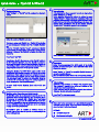
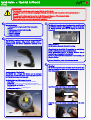
Quick-Guide Flystick2 & DTrack2 01 / 2012 Security advice: The rechargeable batteries may only be charged with the supplied charger. The batteries must be removed before shipping the Flystick2, otherwise the radio transmitter could be started by shock or vibration. The rechargeable batteries must be inserted into the battery pack taking care of the indicated polarity. CAUTION: Risk of explosion if battery is replaced by an incorrect type! Dispose used batteries according to governmental regulations. i 1 Included in delivery: ✔ 1 battery pack including 3 standard AAA rechargeable batteries ✔ 1 battery charger (100-240 Volt, 50-60 Hz) ✔ 1 USB radio transceiver ✔ 1 USB cable extension ✔ 1 hexagon key (2mm) 2 The USB radio transceiver has to be plugged into any USB port of the ARTTRACK Controller (ATC) before the controller is switched on. During operation, please do not unplug the USB radio transceiver. 1 The Flystick2 is a wireless input device for usage with all ART optical tracking systems, using passive markers under a protecting hood and wireless transmission operating in the 2.4GHz band. 2 Switch on the ATC. LED (2) lights continuously while ATC is booting. When DTrack2 is started, LED (1) is switched on and indicates that the radio transceiver was correctly initialized. During measurement, LED (1) is flashing whenever data is received from or transmitted to the Flystick2. In case of unsuccessful data transmission to the Flystick2, LED (2) starts flashing. For more information, please refer to the user manual. 3 Control elements of the Flystick2: The Flystick2 has a trigger, four buttons and an analogue joystick with an additional button functionality. All controls of the Flystick2 can be used simultaneously. The Flystick2 has two LEDs to signal its state: ● green flash … data has been transmitted successfully ● yellow flash … data has not been transmitted successfully ● flashing yellow periodically … indicates low battery – please recharge soon ● yellow permanently lit … registering phase Mounting: The battery compartment is at the lower end of the handle. It is fixed by a single screw, which can be opened using the supplied 2mm hexagon key. Insert the battery pack taking care of the polarity. !! Apply the cover of the battery compartment and fix the screw again. Quick-Guide 4 Flystick2 & DTrack2 Flystick configuration: Select “Settings” → “Flystick” and the configuration window is opened. 6 Body calibration: If the Flystick2 has been recognized correctly in step 4 please select “Calibration” → “Body”. In the appearing dialogue, the body to be selected is named “Flystick body 01”. Please define the orientation of the body coordinate system relative to the body (default setting is due to body). Make sure that all markers (depending on the target: four or five) of the Flystick2 are seen by the cameras using the “Monitor 2DOF” view which appears in the background. Define the number of Flysticks to be used. You have to assign your Flystick2 to a 'Flystick ID' by selecting 'F1' and selecting your Flystick2 out of the “available Flysticks” list. If the list “available Flysticks” doesn't contain your Flystick2 (represented by its serial number) although it is already present, just press a button of the Flystick2 to register it at the radio transceiver. Press “Calibrate” → the calibration starts within 5 seconds. Press “Select” and “OK”. Depending on the ATC, there are one or two Flystick1 entries in the list “available Flysticks“, even if no Flystick1 is present in the volume. This is due to the fact that the Flystick1 connects via serial COM-port which cannot be polled automatically. If you are using a Flystick1 please refer to the Flystick1 manual. Ticking the checkbox “use 6DOF filter” applies a filter to the measurement data in order to remove the jitter of the position measurement. If your application has been configured to use the output format of the Flystick1, you can simply tick the checkbox “use old output format” in order to be compatible. Using the old format will automatically change the analogue joystick to digital and make the leftmost button unusable. 7 Select “Display” → “Flystick” to see which Flystick2 buttons are currently pressed by the user. These are indicated by blue fields in the corresponding column. 8 For more details on the Flystick2, please refer to the user manual. 5 MultiUser option (if more than one Flystick is used): The MultiUser option is an enhancement especially for VR / AR applications when working with more than one Flystick. Up to six users can be equipped with a Flystick and a head target (usually mounted on glasses). The software DTrack2 tracks them all, but only transmits the data pair (Flystick and head body) of one user. Switching between the single users can be done by just pressing one of the Flystick buttons. The MultiUser option is available as additional license for DTrack2 if two or more (max. 6) Flysticks are participating in the entire tracking system. Display Data: During DTrack measurement the 6DOF results of the tracked Flystick2 are listed among the other calibrated bodies in the Display Data window. Output settings: In DTrack2, select “Settings“ → “Output“. You can either select “this computer” (remote PC) or enter an IP address of the computer you want to send data to. Please make sure that the checkbox for Flystick data is ticked. Otherwise, the data will not be transmitted. Press “Start” to start measurement. i Please refer to the user manual for a more detailed description of the ART tracking system. If you need further assistance please do not hesitate to contact our support: ART GmbH +49 (0)881-92530-00 http://www.ar-tracking.de © Copyright 2012 ART GmbH