1
weiSSer Text als Fake ...
System user manual
R
SMARTTRACK & DTrack
version 2.7
January 2012
c
2012
by ART GmbH
Contents are subject to
change without notice
dasbetrifft die gesamte seitenbreite der seite des
Trademarks
The following overview shows the registered trademarks of ART GmbH (Advanced Realtime Tracking GmbH):
trademarks
illustrated as
R
A.R.T.
R
ARTtrack
R
DTrack
R
smARTtrack
ART
ARTTRACK
DTrack2
SMARTTRACK
in Germany
in the EU
in the USA
×
×
×
×
×
×
×
×
×
×
×
×
×
R
R
Microsoft
and Windows
are trademarks registered in the United States and
other countries by the Microsoft Corporation.
The company names and product names written in this manual are trademarks
or registered trademarks of the respective companies.
License agreement
The license provider guarantees the license holder a personal right to use the
DTrack2 software. A single license entitles the license holder to use the
software on all computers and networks of the license holder’s
branch/subsidiary office.
In no event shall ART GmbH be liable for any incidental, indirect, or
consequential damages whatsoever (including, without limitation, damages for
loss of business profits, business interruption, loss of business information, or
any other pecuniary loss) arising out of the use of or inability to use the software
or hardware.
c
1999
- 2012 by ART GmbH
Am Öferl 6
D-82362 Weilheim i. OB
Germany
T +49 (0)881-92530-00
v +49 (0)881-92530-01
http://www.ar-tracking.de
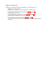
What’s new in version v2.7?
Following, a short overview of the main new features in DTrack2 version v2.7:
• Support for the SMARTTRACK :
Introduction of a simplified DTrack2 Frontend for the SMARTTRACK
• Enhancement for the Room adjustment (chapter 4.2.4.4 on page 54):
one-click adjustment of axes
• Password protection of configurations (chapter 4.2.4.2 on page 46):
protect important configurations with a password
• Tracking frequency status display (chapter 4.2.1.5 on page 34):
the status display changes its colour to red in case the effective tracking frequency
decreases
Contents
Terms and definitions . . . . . . . . . . . . . . . . . . . . . . . . . . . . . . . . .
7
1 Security advice
1.1 Symbols and their meaning . . . . . . . . . . . . . . . . . . . . . . . . . . .
1.2 Safety warnings . . . . . . . . . . . . . . . . . . . . . . . . . . . . . . . . .
8
8
8
2 Introduction
11
3 Markers and targets (rigid bodies)
13
3.1 Passive markers . . . . . . . . . . . . . . . . . . . . . . . . . . . . . . . . . 13
3.2 Active markers . . . . . . . . . . . . . . . . . . . . . . . . . . . . . . . . . . 14
3.3 Standard targets . . . . . . . . . . . . . . . . . . . . . . . . . . . . . . . . . 17
4 System setup
4.1 The SMARTTRACK . . . . . . . . . . . . . . . . . . . . . . . . .
4.1.1 The controller inside the SMARTTRACK . . . . . . . . .
4.1.2 Setting a static IP address without the DTrack2 Frontend
4.1.3 The setup file . . . . . . . . . . . . . . . . . . . . . . . . .
4.1.4 The information file . . . . . . . . . . . . . . . . . . . . . .
4.1.5 Wake On LAN . . . . . . . . . . . . . . . . . . . . . . . .
4.1.6 Remote command strings . . . . . . . . . . . . . . . . . .
4.2 DTrack2 frontend software . . . . . . . . . . . . . . . . . . . . .
4.2.1 Getting started . . . . . . . . . . . . . . . . . . . . . . . .
4.2.1.1 Installation guide (Windows) . . . . . . . . . . .
4.2.1.2 Installation guide (Linux) . . . . . . . . . . . . .
4.2.1.3 Software update . . . . . . . . . . . . . . . . . .
4.2.1.4 Start DTrack2 frontend software . . . . . . . . .
4.2.1.5 Connecting to the SMARTTRACK . . . . . . .
4.2.1.6 Adjustment of the SMARTTRACK . . . . . . . .
4.2.2 Room calibration . . . . . . . . . . . . . . . . . . . . . . .
4.2.3 Body calibration . . . . . . . . . . . . . . . . . . . . . . .
4.2.4 Menu structure . . . . . . . . . . . . . . . . . . . . . . . .
4.2.4.1 Overview . . . . . . . . . . . . . . . . . . . . . .
4.2.4.2 Menu DTrack2 . . . . . . . . . . . . . . . . . . .
4.2.4.3 Menu Settings . . . . . . . . . . . . . . . . . . .
4.2.4.4 Menu Calibration . . . . . . . . . . . . . . . . . .
4.2.4.5 Menu Display . . . . . . . . . . . . . . . . . . .
4.2.4.6 Menu About . . . . . . . . . . . . . . . . . . . .
5 Interaction devices
.
.
.
.
.
.
.
.
.
.
.
.
.
.
.
.
.
.
.
.
.
.
.
.
.
.
.
.
.
.
.
.
.
.
.
.
.
.
.
.
.
.
.
.
.
.
.
.
.
.
.
.
.
.
.
.
.
.
.
.
.
.
.
.
.
.
.
.
.
.
.
.
.
.
.
.
.
.
.
.
.
.
.
.
.
.
.
.
.
.
.
.
.
.
.
.
.
.
.
.
.
.
.
.
.
.
.
.
.
.
.
.
.
.
.
.
.
.
.
.
.
.
.
.
.
.
.
.
.
.
.
.
.
.
.
.
.
.
.
.
.
.
.
.
22
22
25
26
27
28
28
29
31
31
31
32
33
33
33
35
37
40
45
45
46
46
53
57
58
60
5
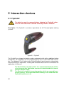
5.1 Flystick2 . . . . . . . . . . . . . . . . . . . . . . . . . . . . . . . . . . . . . . 60
5.2 Flystick3 . . . . . . . . . . . . . . . . . . . . . . . . . . . . . . . . . . . . . . 65
6 General Information
71
6.1 Service . . . . . . . . . . . . . . . . . . . . . . . . . . . . . . . . . . . . . . 71
6.2 Cleaning of the equipment . . . . . . . . . . . . . . . . . . . . . . . . . . . . 71
6.3 Warranty and liability . . . . . . . . . . . . . . . . . . . . . . . . . . . . . . 71
A Technical specifications
73
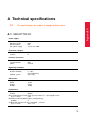
A.1 SMARTTRACK . . . . . . . . . . . . . . . . . . . . . . . . . . . . . . . . . 73
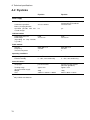
A.2 Flysticks . . . . . . . . . . . . . . . . . . . . . . . . . . . . . . . . . . . . . . 74
A.3 Overall system . . . . . . . . . . . . . . . . . . . . . . . . . . . . . . . . . . 75
B Radiation Protection for SMARTTRACK
B.1 Used Instructions . . . . . . . . . . . . . . . . . . . .
B.2 Classification of the LED Flash . . . . . . . . . . . .
B.3 Maximum Permitted Exposure of Radiation (MPER)
B.4 Resulting Safety Instructions . . . . . . . . . . . . .
.
.
.
.
.
.
.
.
.
.
.
.
.
.
.
.
.
.
.
.
.
.
.
.
.
.
.
.
.
.
.
.
.
.
.
.
.
.
.
.
.
.
.
.
.
.
.
.
.
.
.
.
76
76
76
76
77
C Technical Appendix
C.1 Definition of Coordinates and Rotations . . . . . . . . . . . . . . . . . . . .
C.1.1 Room Calibration . . . . . . . . . . . . . . . . . . . . . . . . . . . . .
C.1.1.1 Room Adjustment . . . . . . . . . . . . . . . . . . . . . . .
C.1.2 Body Calibration . . . . . . . . . . . . . . . . . . . . . . . . . . . . .
C.1.2.1 Definition of the Coordinates by the Body itself . . . . . . .
C.1.2.2 Definition of the Coordinates by the Room Coordinate System, with Origin in the Center of the Markers . . . . . . . .
C.1.2.3 Definition of the Coordinates by the Room Coordinate System, with Origin in a Marker . . . . . . . . . . . . . . . . . .
C.1.3 6DOF Results . . . . . . . . . . . . . . . . . . . . . . . . . . . . . .
C.1.4 3DOF Data . . . . . . . . . . . . . . . . . . . . . . . . . . . . . . . .
C.1.5 Flystick devices . . . . . . . . . . . . . . . . . . . . . . . . . . . . . .
C.1.5.1 Flystick2 . . . . . . . . . . . . . . . . . . . . . . . . . . . .
C.1.5.2 Flystick3 . . . . . . . . . . . . . . . . . . . . . . . . . . . .
C.2 Output of Measurement Data via Ethernet . . . . . . . . . . . . . . . . . . .
C.2.1 Frame Counter . . . . . . . . . . . . . . . . . . . . . . . . . . . . . .
C.2.2 Timestamp . . . . . . . . . . . . . . . . . . . . . . . . . . . . . . . .
C.2.3 Standard 6DOF Bodies . . . . . . . . . . . . . . . . . . . . . . . . .
C.2.4 Flysticks . . . . . . . . . . . . . . . . . . . . . . . . . . . . . . . . . .
C.2.5 Flysticks (Old Format) . . . . . . . . . . . . . . . . . . . . . . . . . .
C.2.6 Additional 3DOF Markers . . . . . . . . . . . . . . . . . . . . . . . .
C.2.7 Additional Informations . . . . . . . . . . . . . . . . . . . . . . . . .
79
79
79
79
80
80
List of Figures
88
List of Tables
89
Index
90
6
80
80
81
81
81
82
82
83
83
84
84
85
86
86
87
term
definition
3DOF
6DOF
base
three degrees of freedom (i.e. only position)
six degrees of freedom (i.e. position and orientation)
imaginary connecting line between the two integrated cameras
of the SMARTTRACK
teach the system the geometry of a rigid body
rigid arrangement of several single markers (see also "target")
belongs to the room calibration set and defines origin and orientation of the room coordinate system
equipment to mount an infrared camera to the ceiling
body calibration
body, rigid body
calibration angle (410mm or 710mm)
ceiling suspension
DTrack2
backend software
frontend software
infrared optical tracking
license code (license key)
marker
measurement volume
modulated flash
mutual blinding
room calibration
room calibration set
target
tracking
virtual point cloud
wand
Linux-based software which does all necessary calculations
graphical user interface to control the SMARTTRACK
position measurement of bodies (subjects or objects) based
upon infrared light and optical measurement procedures
software key to unlock certain capabilities of the tracking system
object either made of retro reflective material or LED for position
tracking (3DOF)
defines the volume where optical tracking is possible
infrared signal which is used for wireless synchronization
one camera sees disturbing reflections caused by the infrared
flashes of another one
teach the system the position of each camera and define origin
and orientation of the room coordinate system
consists of angle and wand
rigid arrangement of several single markers ( = rigid body)
position measurement of bodies that move in a defined space
used for calculating the relative positions of the IR cameras
precalibrated stick carrying two markers. The wand belongs to
the room calibration set and is used to generate a virtual point
cloud and to scale the system
7
Chapter 0
Terms and definitions
1 Security advice
1.1 Symbols and their meaning
You can find the following symbols and their signification on the equipment or in the manual:
i
Z
Useful and important notes.
Important notes, which may lead to system malfunction or to the
loss of warranty by non-observance.
Important safety warning to assure operation safety.
These warnings have to be considered, otherwise user
and equipment could be endangered, the equipment could be
damaged or the function of the equipment is not warranted.
Safety warning for infrared radiation.
These warnings have to be considered, otherwise users eyes
could be endangered.
Table 1.1: Symbols and their meaning
1.2 Safety warnings
Z
Safe operation of the equipment is only warranted if the warnings in
this manual and on the equipment are observed.
• Never use the equipment if any part looks damaged.
• Safe operation is not possible, if
– the housing is damaged,
– any fluid attains in the housing,
– objects attain inside the equipment,
– the equipment shows any visible faults (smoke, sparks, fire, smells, etc.) or
– the power cord is damaged.
• In any of the cases mentioned above (or similar) pull the power cord out of the power
8
1.2 Safety warnings
socket immediately. Otherwise, users or environment are endangered. Please contact the ART service.
• Never open the equipment! Only personnel authorized by ART is allowed to open
the equipment. Inside of the equipment there are various hazards like high voltage,
electric shocks - even if the equipment is disconnected - which can lead to death on
contact. In case of malfunction of the equipment please contact the ART service.
• Only peripheral devices which meet the safety requirements of EN/IEC 60950 for
extra low voltage may be attached on Ethernet-, BNC- and the DC-circuit of the
equipment.
• The cameras emit infrared-light flashes which can pose a threat to human health
and the environment. Keep enough distance to the flashes of the cameras or the IR
flashes. Never look directly into the IR light sources. Carefully read chapter B.
• Be sure that the cameras are firmly mounted in the correct position.
• Do not touch the front pane of the cameras, since the acrylic pane and the lens are
highly sensitive surfaces. Be careful to avoid permanent damages (e.g. scratches).
Only touch the housings of the cameras.
• The ventilation holes of the SMARTTRACK must not be covered. Air circulation is
necessary to prevent the cameras from overheating. If the air circulation is restricted
overheating will damage the cameras. The minimum distance between equipment
and environmental objects has to be greater than 3 cm.
• The equipment has to be attached to a power socket with grounding. If the grounding wire is defective the requirement of the safety and the electromagnetic compatibility (EMC) are not guaranteed. To check the function of the grounding wire ask
your regional located electrician.
• Before switching on any device, verify that voltage and frequency of your electric
installation are within the allowed ranges of the equipment. The characteristics of
the equipment can be found on the appliance rating plate or in chapter A. The appliance rating plates are on the equipment’s housing (SMARTTRACK on the backside
of the housing)
• The power switch on the backside does not completely separate the devices from
the electricity network. To completely separate the equipment from the electricity
network the power plug must be disconnected from the power socket. The power
plug has to be accessible freely. The power socket must be close to the equipment.
• The cabling should be realized such that
– no one can stumble on the cords,
9
Chapter 1
• Never change or alter the equipment, neither mechanically nor electrically. Only the
components described by ART shall be used. The conformity and the warranty of
the producer (ART ) expire by non-compliance.
1 Security advice
– the cords cannot be damaged,
– the cords cannot tear down the cameras.
Install a pull relief!
• Only use original ART (or ART authorized) components and accessories. Using
non-original components or accessories may damage the equipment, cause malfunctions or may void operation safety. The provided components and original accessories can be found in chapters 4 and 5. Only use the originally provided external
power supply for operating the SMARTTRACK
• The equipment must not be dropped and/or knocked.
• Do not use any solvents or water to clean the cameras. For more information about
cleaning the cameras please read chapter 6.2 on page 71.
• Never expose the equipment to high humidity levels or condensating humidity. Protect the cameras against water and chemicals.
• The equipment must not be operated in environments with intensive formation of
dust or hot environments where temperatures rise above 40◦ C (100◦ F).
Z
10
ART explicitly denies any liability or warranty if the product is modified
in any way or not used according to this manual and the specification
labels on the equipment.
2 Introduction
Position and/or orientation of those rigid bodies can be measured. If only the spatial position (X, Y, Z) is measured we call this "three degrees of freedom" (3DOF) tracking. The
simultaneous measurement of position and orientation (three independent angular coordinates) is called "six degrees of freedom" (6DOF) tracking.
Single markers are sufficient if only 3DOF coordinates are needed. For 6DOF tracking, a
rigid body is mandatory.
Passive markers are covered with retro reflective material - they act as light reflectors.
Active light emitters (i.e. based on infrared LEDs) are called active markers.
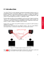
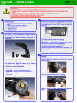
Figure 2.1: Principle of optical tracking (stereo vision)
Figure 2.1 shows the principle of infrared optical tracking with a two-camera system and
a standard target. The SMARTTRACK makes use of the same principle.
11
Chapter 2
The SMARTTRACK is a fully integrated stand-alone infrared optical tracking system. It is
designed to be used in small volumes (approx. 2m3 ). In this user manual we are going to
perceive "tracking" as measurement of the position of objects or subjects that move in a
defined space. These objects or subjects to be tracked have to be equipped with single
markers or rigid arrangements of markers (= rigid body or target).
2 Introduction
The cameras are sending out synchronized IR flashes which are reflected towards the
lens by the retro reflective material which is covering the markers of the target. The
integrated tracking cameras scan a certain volume, detect the IR radiation that is reflected by the markers and create a greyscale image based on the received IR radiation. The SMARTTRACK calculates the 2D marker positions with high accuracy using
pattern recognition internally. A mean 2D-accuracy of 0.04 pixels (0.1 pixels maximum
2D-deviation) is standard in ART tracking cameras. Then, based on the 2D data, the
SMARTTRACK calculates 3DOF or 6DOF data. The base for this calculation is that the
cameras’ field of views are overlapping. DTrack2 calculates the path of the optical rays
from the cameras to the markers and delivers the ray intersections in three-dimensional
coordinates. These intersections are the positions of the markers.
The position and orientation of the cameras are known from the room calibration. During
body calibration, DTrack2 identifies certain marker arrangements as rigid bodies. Based
upon this, DTrack2 is able to calculate 6DOF data and, finally, knows position and orientation of the target and, therefore, of the object or subject to be tracked.
In optical tracking systems you have to be aware that tracking is only possible as long as
the target is positioned in tracking range of the cameras and is not occluded by any other
objects or the object to be tracked. More in detail, at least four markers of a target have
to be visible for a minimum of two cameras to enable tracking.
i
12
The SMARTTRACK has a limited field-of-view and range! It is designed
to be used in small volumes. Please refer to chapter 4.1 on page 22 for
more information on the tracking volume of the SMARTTRACK .
3 Markers and targets (rigid bodies)
3.1 Passive markers
The passive markers used in ART tracking systems are retro reflectors. These markers
reflect the incoming IR radiation into the direction of the incoming light. More precise: the
IR radiation is reflected into a narrow range of angles around the (opposite) direction of
the incoming light. Passive markers can be either
1. spherical markers:
+ excellent visibility from any perspective,
- expensive fabrication,
- sensitive surface,
Chapter 3
- target requires larger volume → danger of mechanical damage.
2. flat markers:
+ cheap,
+ flat targets possible,
+ robust surface because cover may be applied,
- the angular range of visibility is limited to approx. ±45◦ .
Passive markers are mostly spheres covered with retro reflecting foils. However, they can
also be stickers made from retro reflecting material.
Retro reflecting sheets or foils available on the market can be based on two different optical principles:
1. Triple mirrors, which are arranged such that their planes
form angles of 90◦ by pairs, are reflecting light in the described way. Mostly foils with arrangements of many very
small mirrors in a plane are used.
13
3 Markers and targets (rigid bodies)
2. Glass balls (with a proper refraction index) are focussing
incoming light approximately to the opposite surface of the
ball. A layer of microscopic glass balls, carried by a reflecting material, acts as a retro reflector. These foils can be
fabricated on a flexible carrier material, thus they are widely
used for equipping spherical markers with retro reflecting
surfaces.
i
ART spherical markers are covered with retro reflecting foils, based on
the glass balls principle.
Z
The quality of the markers decreases when they are in contact with
dust, dirt, fat, liquids, glue or comparable contaminants. Please make
sure that the markers are not touched or damaged.
3.2 Active markers
Basics
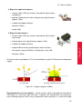
Active markers are light (i.e. infrared light) emitting elements, mostly LEDs.
In ART tracking systems four types of LED-based active markers may be used, depending on the application:
1. Single LEDs without diffusor sphere:
+ can be covered with acrylic protection film,
+ results in simple and robust markers providing visibility up
to high distances (up to 10m),
- the angular range of visibility is limited to approx. ±60◦ .
2. Single LEDs with diffusor sphere:
+ for optimum angular range of visibility,
- distance between marker and tracking camera is limited to
a short distance (up to 4.5m).
14
3.2 Active markers
3. Big active spherical markers:
+ several single LEDs per marker, covered with light scattering spheres,
+ provide visibility from all sides and up to very high distances
(approx. 20m),
+ suitable for outdoor tracking,
- diameter: 50mm,
- weight: 50g.
4. Big active flat markers:
+ several single LEDs per marker, covered with light scattering surface,
+ tracking up to very high distances (approx. 20m),
+ suitable for outdoor tracking,
Chapter 3
+ magnetic base for easy positioning on metal surfaces,
- the angular range of visibility is limited to less than 180◦ ,
- diameter: 30mm.
All active markers provided by ART are controlled by a special PC board and need power
supply.
(a) Single LED
(b) Single LED with diffusor sphere
Figure 3.1: Angular range of visibility
Synchronization of active markers Active markers could in principle be activated in
CW mode (i.e. continuous light emission). However, this would not be very clever because tracking cameras have a very narrow time slot of sensitivity, i.e. most of the light
15
3 Markers and targets (rigid bodies)
emitted by the markers would be useless for tracking. As a consequence, maximum distance between cameras and marker would be very short due to an upper limit of power
dissipation allowed for each single LED. Therefore, all active markers provided by ART are
emitting radiation only when the tracking cameras are sensitive, thus having to be synchronized with the cameras.
Synchronization can be done by a wired connection between the tracking system and the
pc-board controlling the active markers, but can also be done in a wireless way.
For wireless synchronization a coded IR flash is being sent out by a tracking camera. The
active marker’s PC board recognizes the coded flash and activates the LEDs.
16
3.3 Standard targets
Type
Description
Hand target
Weight
Marker
size
The hand target is designed for hand track- 25g / 0.9oz
ing in usability and assembly studies respectively. It is also frequently used as a
small general-purpose target. Due to the
small size this target is easily occluded by
the hand carrying it. Therefore, proper arrangement of tracking cameras has to be
used in order to avoid occlusions.
(110 × 80 × 28)mm
12mm
Large hand target
This hand target is designed for hand tracking in a two camera tracking system. Its
large size allows to move the hand in almost all directions, without losing tracking.
30g / 1.1oz
(170 × 120 × 35)mm
12mm
Claw target
The claw target looks just the same as the
hand target. But it comes in a bigger size
and is equipped with bigger markers.
35g / 1.2oz
(160 × 110 × 30)mm
16mm
17
Chapter 3
3.3 Standard targets
approx. Dimension
Description
Tree target
Weight
approx. Dimension
Marker
size
Originally designed for tracking HMDs, the 75g / 2.65oz
tree target is a general-purpose target
for tracking from longer distances. It is
equipped with 20mm markers.
(195 × 170 × 120)mm
20mm
Generic glasses target
For head tracking mostly in passive stereo
systems, tracking targets must be fixed to
the stereo glasses. ART offers several
light-weight standard targets for this purpose.
(270 × 120 × 35)mm
12mm
INFITEC PREMIUM target
Target tailored to the INFITEC PREMIUM 26g / 0.9oz
passive stereo glasses.
(225 × 85 × 80)mm
12mm
min:
14g / 0.5oz
max:
22g / 0.7oz
3 Markers and targets (rigid bodies)
18
Type
Type
Description
Weight
approx. Dimension
Marker
size
R
CrystalEyes
2/3 target
Target tailored to the shutter glasses of the
StereoGraphics active stereo system. It fits
R
to both CrystalEyes
2 and 3.
28g / 1oz
(215 × 120 × 60)mm
12mm
R
CrystalEyes
5 target
Target tailored to the shutter glasses of the
StereoGraphics active stereo system. It fits
R
to the CrystalEyes
5.
19g / 0.7oz
(195 × 105 × 40)mm
12mm
NuVision APG6000
and APG6100 target
Target tailored to the NuVision APG6000
and APG6100 shutter glasses.
17g / 0.6 oz
(220 × 125 × 75)mm
12mm
3.3 Standard targets
19
Chapter 3
Description
Weight
approx. Dimension
Marker
size
R
Volfoni EDGE
target
R
Target tailored to the Volfoni EDGE
shut- 23g / 0.7 oz
ter glasses.
(230 × 95 × 60)mm
12mm
R
NVIDIA 3D Vision
Pro Target tailored to the NVidia 3D Vision Pro 25g / 0.9 oz
shutter glasses.
target
(225 × 100 × 60)mm
12mm
NVisor SX 60 target
(300 × 215 × 35)mm
12mm
Target tailored to the NVisor SX 60 head 55g / 1.94oz
mounted display.
3 Markers and targets (rigid bodies)
20
Type
Type
Description
Motion capture targets
ART provides a complete set of targets for
motion capture purposes. All targets are
6DOF targets and can be identified by the
tracking system. A full ART MoCap target
set consists of (subsets can be generated):
1 Glasses target (AGT4)
2 Shoulder targets (UT)
1 Dorsal target (DT)
2 Upper arm targets (HBT)
2 Forearm targets (UBT)
2 Hand targets (HT)
1 Waist target (WT, one-piece)
1 Waist target (WT, multi-part), each
2 Upper leg targets (FBT)
2 Lower leg targets (TBT)
2 Foot targets (FT)
Weight
approx. Dimension
Marker
size
28g / 1.0oz
44g / 1.55oz
84g / 2.96oz
52g / 1.83oz
50g / 1.76oz
25g / 0.9oz
195g / 6.9oz
30g / 1.1oz
99g / 3.49oz
58g / 2.05oz
65g / 2.29oz
(225 × 180 × 95)mm
(90 × 75 × 35)mm
(150 × 65 × 35)mm
(150 × 70 × 35)mm
(150 × 65 × 35)mm
(110 × 80 × 28)mm
(390 × 140 × 50)mm
(90 × 60 × 50)mm
(220 × 120 × 40)mm
(205 × 70 × 35)mm
(95 × 105 × 70)mm
12mm
12mm
12mm
12mm
12mm
12mm
14mm
16mm
16mm
16mm
16mm
Table 3.3: Standard targets overview
3.3 Standard targets
21
Chapter 3
4 System setup
4.1 The SMARTTRACK
Do not look directly into the SMARTTRACK from short distance (<
10cm) for a longer period of time (> 10sec)! Please refer to chapter
B on page 76 for more information.
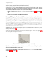
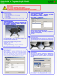
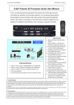
Description The SMARTTRACK is a fully integrated stand-alone infrared optical tracking system. It is designed to be used in small volumes of approx. 2m3 .
Figure 4.1: SMARTTRACK
Tracking volume
Mounting The SMARTTRACK is optimized for a predefined measurement volume. System operation in smaller or bigger measurement volumes can lead to reduced accuracy or
other malfunctions. The measurement volume can be adjusted within certain limits simply
by changing the flash intensity of the SMARTTRACK (see chapter 4.2.4.3 on page 47).
The tracking system is very sensitive to camera movements. Therefore, the cameras have
to be mounted in a way that reduces camera movements (especially vibrations) as much
22
4.1 The SMARTTRACK
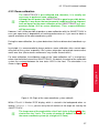
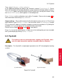
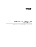
Figure 4.2: Attaching the T-piece to the SMARTTRACK
as possible.
i
Mounting on tripods may be sufficient for presentations and preliminary installations, but is not recommended as a final solution!
Feel free to contact ART in case you want to realise a more complex installation. We will
assist you in your planning.
Make sure you install the system in a way that you can easily access the SMARTTRACK and its cables. Be especially careful to fix it firmly so it cannot fall off.
If the SMARTTRACK is falling down it will be damaged and it exposes a danger to humans and the environment.
Avoid hard shocks! A new camera calibration at the ART facilities
might become necessary in that case.
Chapter 4
The cabling should be performed such that
• no one can stumble on the cords,
• the cords cannot be damaged,
• the cords cannot tear down the cameras,
• the line of sight of the camera is not disturbed.
Inappropriate cabling may imply dangers to both, people and equipment. Cable ducts or fixings should be used and a pull relief should
be installed!
To avoid measurement problems, no light sources or highly reflecting areas should be
visible to the camera. Especially strong point light sources like e.g. halogen lamps and
direct or reflected sunlight may imply problems for the measurement (fluorescent lamps
are ok).
The T-piece for the SMARTTRACK can be attached on both bottom and top side (see
figure 4.2).
23
4 System setup
Only use screws supplied with the carrier for mounting it.
You shall never unfasten other screws of the SMARTTRACK (see chapter 1.2 on page
8). Otherwise, the SMARTTRACK may be damaged and liability and warranty is void.
Furthermore, please make sure the ventilator holes are not covered.
Please refer to 4.2 to learn how to install the DTrack2 frontend software.
24
4.1 The SMARTTRACK
4.1.1 The controller inside the SMARTTRACK
The SMARTTRACK is an integrated tracking system. That means, inside the small housing we integrated not only two tracking cameras but also the Controller which performs all
calculations and generates the data output stream.
The software DTrack2 consists of frontend and backend software. The frontend software
is installed on a remote PC which is connected to the SMARTTRACK via Ethernet. A
GUI for easy handling enables the user to control the tracking system completely from
the remote PC. The benefit is that the system becomes more flexible, i.e. different users
can control the tracking system at any one time (but not simultaneously!) from different
working places.
Furthermore, DTrack2 provides the possibility to control its functions via Ethernet (i.e.
without the DTrack2 frontend software). This is done by establishing a TCP/IP connection with the SMARTTRACK and exchanging short command strings (refer to chapter
4.1.6 on page 29). Please contact ART if you are interested in using this feature.
The SMARTTRACK is equipped with an input for an external synchronization signal (rectangular or video sync signal). The signals for external synchronization are transferred via
BNC connections.
Z
The external sync input is not internally terminated.
When synchronizing with a video input, a T-piece with an external
75Ω terminating resistor should be used if the signal line ends at the
SMARTTRACK .
When using a TTL-signal you should not use a terminating resistor.
However, you should use a shielded cable for the synchronization with
a TTL-signal.
By default, the SMARTTRACK is set up to support DHCP. Connect the Ethernet cable to
your local network and connect the power supply. If you want to set a specific static IP
address before booting the ATC please refer to chapter 4.1.2 on page 26 for more information.
Press the switch on the back to start the SMARTTRACK . If it is booting without connected Ethernet cable it will use its standard IP address.
i
The fall-back IP address of the SMARTTRACK is 192.168.0.1 (subnet
mask 255.255.255.0)!
25
Chapter 4
The backend software, which is Linux-based, runs on the integrated ATC - all necessary
calculations (3DOF, 6DOF data, ...) are done by it. The data and control commands are
interchanged via a TCP/IP connection between the SMARTTRACK and the DTrack2 frontend software on the remote PC. Data output to the application or graphics workstation is
done via a UDP connection.
Interaction devices have to be connected to the respective ports of the SMARTTRACK (refer to chapter 5 on page 60).
4 System setup
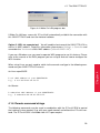
You may configure another static IP address as follows:
• select Settings → Controller
• untick the checkbox DHCP client
• enter IP address and subnet mask
• optionally, enter gateway and nameserver
• reboot the SMARTTRACK for the changes to take effect
Z
Please make sure to remember these settings. Otherwise, your
SMARTTRACK may become unreachable due to wrong IP settings! Refer to chapter 4.1.2 on page 26).
Finally, start the DTrack2 frontend software on the remote PC. Please refer to chapter 4.2
on page 31 for more details.
4.1.2 Setting a static IP address without the DTrack2 Frontend
It is possible to configure the IP address of the SMARTTRACK without the DTrack2 frontend software. You only need a standard USB stick (FAT32 formatted) on which you save
a setup file (format see below).
• Plug in the USB stick. It doesn’t matter if the SMARTTRACK is up and running or
not.
• If necessary start up the SMARTTRACK .
• Wait some time (approx. 20-30 seconds) for the SMARTTRACK to write the two
files onto the USB stick.
• Unplug the USB stick.
• Now, you may view the information file or edit the setup file with any editor (instructions given in the setup file).
• In case you changed the setup file, please plug in the USB stick to the SMARTTRACK again.
• Wait some time (approx. 20-30 seconds) for the SMARTTRACK to read the setup
file.
• Shut down and restart the SMARTTRACK for the changes to take effect.
Now, your SMARTTRACK is configured according to your requirements.
26
4.1 The SMARTTRACK
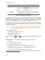
4.1.3 The setup file
This file is used to configure the SMARTTRACK without using the DTrack2 frontend
software regarding three parameters, which are:
• configuring the SMARTTRACK to be a DHCP client,
• setting a static IP address and
• carrying out a factory reset.
Carrying out a factory reset will result in the loss of all your settings!
1# ARTtrack Controller Setup:
2
3
4# ethernet settings:
5# - uncomment just one of the lines starting with ’SETNET’
6
7# ethernet settings: DHCP
8# - uncomment the following line to activate DHCP
9#SETNET="dhcp"
10
11# ethernet settings: fix IP address and subnet mask
12# - uncomment the following line to set a fix IP address and subnet mask
13#SETNET="ip 192.168.0.1 255.255.255.0"
14
15# factory reset of all other settings:
16# - CAUTION: use with care, all your settings will be lost!
17# - uncomment the following line to reset all other Controller settings
18#RESETSETTINGS="yes"
Example:
If you wanted to setup a static IP you would have to remove the ’#’ sign and enter the
desired IP address, here for example: 123.123.0.1
before:
13#SETNET="ip 192.168.0.1 255.255.255.0"
after:
13 SETNET="ip 123.123.0.1 255.255.255.0"
27
Chapter 4
Following, a description of the file (e.g. smarttrack00007_setup.txt) format:
4 System setup
4.1.4 The information file
This file contains the current settings of the SMARTTRACK . Following, a description of
the file format (e.g. smarttrack00007_info.txt):
ARTtrack Controller Information:
Serial Number
: 00007
Ethernet (LAN)
: dhcp
Ethernet IP (LAN) : 10.10.5.22 255.255.0.0 10.10.0.253
Ethernet MAC (LAN): 00:24:1D:00:C3:B3
4.1.5 Wake On LAN
The SMARTTRACK is capable of Wake On LAN (WOL) if it has been forced into standby
mode before by the user (DTrack2 → ARTtrack Controller standby ).
There are two options for waking up the controller remotely:
1. you may use DTrack2 or
2. use a separate tool (Windows: WOL program; Linux: console-based command).
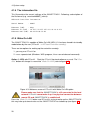
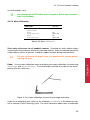
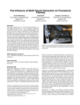
Option 1 - WOL via DTrack2 Start the DTrack2 frontend software as usual. The ’Connect’ button will change its name into ’Wake On LAN’ (refer to figure 4.3).
Figure 4.3: Welcome screen of DTrack2 with Wake On LAN option
Please make sure that the SMARTTRACK is still connected to the local
network! DTrack2 cannot wake it up if no physical connection between
remote PC and SMARTTRACK is established!
Press the ’Wake On LAN’ button and DTrack2 is trying to wake up the SMARTTRACK this may take up to two minutes as the SMARTTRACK has to boot up (see figure 4.4).
28
4.1 The SMARTTRACK
Figure 4.4: Wake On LAN progress bar
If Wake On LAN was successful DTrack2 will automatically establish the connection with
this SMARTTRACK and start the frontend software.
Option 2 - WOL via separate tool You will need the hostname of the SMARTTRACK as
well as its MAC address. To get this information, please press Settings → Controller and
remember the ’hostname’ and its MAC address (’ethernet-MAC LAN’).
If you are a Windows user you need a separate WOL program to use this feature. Please
refer to the manual of the WOL program you are using to find out how to configure the
WOL function.
When using Linux you only need to switch to the console and type in the following command and your SMARTTRACK restarts:
Chapter 4
for Linux openSUSE:
$ wol <MAC address of your SMARTTRACK>
e.g.: $ wol 00:1D:92:3A:58:5F
for Ubuntu:
$ wakeonlan <MAC address of your SMARTTRACK>
e.g.: $ wakeonlan 00:1D:92:3A:58:5F
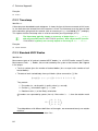
4.1.6 Remote command strings
The following commands may be used in combination with the DTrack2 SDK to control
the tracking system remotely (e.g. with your media control) and without the DTrack2 frontend. The DTrack2 SDK is available from ART upon request.
29
4 System setup
Command string (always preceded by "dtrack2")
Description
tracking start
Start the measurement
tracking stop
Stop the measurement
set config active_config <name>
Change the configuration to <name>
set output net <channel id> udp <host> <port>
Configure where the data has to be sent to
example: dtrack2 set output net ch02 udp 231.231.0.1 5003
set output net <channel id> multicast <host> <port>
Configure where the data has to be sent to
example: dtrack2 set output net ch02 multicast 231.231.0.1 5003
set output active <channel id> <output type> <yes/no> Activate or deactivate the data output and specify
the data to be transmitted
example: dtrack2 set output active ch02 all yes
system shutdown
Force the SMARTTRACK to go into standby
30
4.2 DTrack2 frontend software
4.2 DTrack2 frontend software
The software DTrack2 is intended to run on a remote PC (Windows or Linux). The
SMARTTRACK can be controlled remotely via Ethernet. The software DTrack2 itself is
delivered via CD-ROM.
Z
DTrack2 supports the SMARTTRACK starting with version v2.7.0.
Please don’t use it with older versions of the DTrack2 frontend software.
4.2.1 Getting started
Please refer to chapter A.3 on page 75 for more information on supported operating systems.
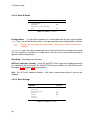
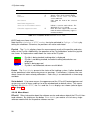
4.2.1.1 Installation guide (Windows)
Click Next to continue and to start the installation
process for ART DTrack2 software. Administrator rights are not necessary.
Now, please choose the destination folder in
which you want to install DTrack2 .
31
Chapter 4
Run the installation executable "DTrack2_v2.x.x_win32_install.exe" and the installation
wizard of DTrack2 starts.
4 System setup
Please read the license terms carefully and
press I Agree if you agree indeed. A new window shows the installation progress.
The installation of the DTrack2 software is complete now. DTrack2 has been installed on your
computer. Click Next.
Press Finish to complete the DTrack2 setup wizard. Now, you can use DTrack2 .
4.2.1.2 Installation guide (Linux)
The software is packed in an archive (DTrack2_v2.x.x_linux32.tar.gz). You do not need
to have administrator rights to extract all files to a user-defined folder. In a shell, change to
the user-defined folder and type in the command tar xvf DTrack2_v2.x.x_linux32.tar.gz
in order to extract the files. For ease of use, you may create a shortcut on the desktop.
DTrack2 can be started with the command ./DTrack2.
32
4.2 DTrack2 frontend software
Z
The DTrack2 frontend software for Linux is a 32 Bit application. If you
are running a 64 Bit Linux please install all 32 Bit extensions for your
distribution.
4.2.1.3 Software update
Please contact ART in order to receive the latest DTrack2 software. For the installation
of the update, please proceed as mentioned before in chapters 4.2.1.1 and 4.2.1.2.
4.2.1.4 Start DTrack2 frontend software
When you start DTrack2 on the remote PC you will see the following start window (see
figure 4.5).
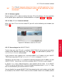
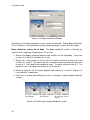
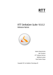
4.2.1.5 Connecting to the SMARTTRACK
The first time you start DTrack2 , no default SMARTTRACK will be found and another
window will be opened automatically (see figure 4.6). The radio button at position Specific ARTtrack Controller will be ticked.
If you know the name (typically like "smarttrack-00001") or IP address of your SMARTTRACK you may enter it in line hostname or IP address and press Connect.
Otherwise, you can select Scan, if you don’t know the hostname or the IP address of your
SMARTTRACK . You will see a list of the available SMARTTRACKs in your network.
In column Name every SMARTTRACK in your network will be listed. If no SMARTTRACK or not the desired SMARTTRACK is listed there please press Update list. Now,
the list should contain your desired SMARTTRACK .
You can identify the correct SMARTTRACK by comparing the serial number on the label
on the back of the SMARTTRACK with the serial number listed in this window (column
33
Chapter 4
Figure 4.5: Welcome screen of DTrack2
4 System setup
(a) specific ATC
(b) scan the network
Figure 4.6: ARTTRACK Controller Selection
Serial). SMARTTRACKs set in grey are used by other PCs in the network (→ IP address
listed at the bottom of the welcome screen). It is only possible to connect to SMARTTRACKs set in black. Select the entry which fits to your desired SMARTTRACK and
press Connect.
The next time you start DTrack2 your SMARTTRACK is still known by the software and
DTrack2 automatically searches for it. The welcome screen shows the name of your
SMARTTRACK . If this is the one you want to connect to, just press Connect.
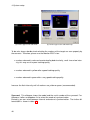
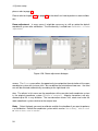
The graphical user interface The graphical user interface of DTrack2 offers different
views which can be switched on and off by the user:
1.
Monitor 2DOF
Graphical display of markers seen/tracked by the cameras.
Colour code signifies the circularity or the size of the markers, respectively.
2. Event Display
Displays DTrack2 events (e.g. "no valid room calibration")
3. Data Display
Displays measurement results (6DOF and/or 3DOF)
4. Flystick
Shows the measurement results (6DOF and/or 3DOF) and
the operation of the buttons and the joystick
5. Measurement Tool Shows the measurement results of the Measurement
Tool and, if assigned, the reference body
By default the first three are shown (see figure 4.7).
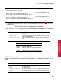
In the status bar, a button for starting and stopping of the measurement is integrated.
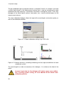
Additionally, you may retrieve information regarding the cameras connected, the synchronization frequency, the number of bodies tracked and the number of single markers seen.
The synchronization frequency field is changing its colour to yellow, orange and red in
case the effective frequency is decreasing (see figure 4.8):
• grey: max. 5 frames per minute lost (i.e. 3600 frames per minute are transmitted)
• yellow: 5 - 10 frames per minute lost
34
4.2 DTrack2 frontend software
• orange: 10 - 15 frames per minute lost
• red: > 15 frames per minute lost
(a) yellow: 5 - 10 frames per
minute lost
(b) orange: 10 - 15 frames per
minute lost
Chapter 4
Figure 4.7: Graphical user interface of DTrack2
(c) red: > 15 frames per minute
lost
Figure 4.8: Visualization of the synchronization frequency decrease
4.2.1.6 Adjustment of the SMARTTRACK
So far, the SMARTTRACK has been mounted and connected to the remote PC either
directly or via a network.
Now, adjust the SMARTTRACK in a way that allows to cover the desired measurement
volume as good as possible. To check that, DTrack2 provides the Monitor 2DOF display
that essentially is a graphical display of the field of view of the SMARTTRACK and of the
35
4 System setup
markers that are seen by it (presented two-dimensional).
As the SMARTTRACK is pre-calibrated there’s basically not much more to do - you can
start tracking right away. If you need to arrange the coordinate systems of the tracking
system and the application software you’ll have two possibilities:
1. within DTrack2 go to Calibration → Room adjustment (refer to 4.2.4.4 on page 54),
or
2. adjust the values within the application software.
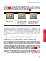
Monitor 2DOF display The Monitor 2DOF view shows two black windows for the integrated IR cameras (equivalent to the field of view) with a schematic display of positions
and sizes of all recognized markers. A simple colour code signifies the size and the circularity of the markers (green = very good quality, yellow = good quality, red = bad quality).
As a rule of thumb, for measurement applications with high accuracy requirements the
markers should be displayed in green; for VR applications yellow markers are always ok.
The Monitor 2DOF display is particularly useful for the final adjustment (especially orientation adjustments) of the SMARTTRACK .
Additionally, the intensity of the brightest pixel in the field of view is shown using a bar
display (refer to figure 4.7).
A click with the right mouse button into one of the windows opens a menu (see figure 4.9)
with settings for the respective camera.
Figure 4.9: Monitor 2DOF view menu (e.g. camera 1)
By clicking and holding the left mouse button on one of the camera displays, its position
can be moved within Monitor 2DOF view.
A more detailed description of the features of the Monitor 2DOF view can be found in
chapter 4.2.4.5 on page 57.
36
4.2 DTrack2 frontend software
4.2.2 Room calibration
i
The SMARTTRACK is pre-calibrated and, therefore, it is usually not
necessary to perform a room calibration.
Although we will protect the SMARTTRACK as good as possible before
shipment, it may occur that environmental conditions during shipment
have an impact on the room calibration of the SMARTTRACK (e.g. temperatures below -30◦ C or severe vibrations). Then, a room calibration
will be necessary.
However, it will still be possible to perform a room calibration with the SMARTTRACK in
case you experience a degradation of tracking performance or if you want to obtain a
special orientation of the room coordinate system.
During the room calibration, the system determines the three-dimensional coordinate system.
In principle, it is recommended to always perform a room calibration after a certain operating time of the system, especially if the system setup does not exclude camera movements over time (these camera movements may also be thermal drifts!).
Chapter 4
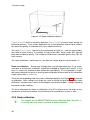
For room calibration, the calibration angle of the "room calibration set" is inserted anywhere into the field of view of the SMARTTRACK . By default, the origin of the calibration
system lies centered between the two status LEDs in the front. The orientation is as
shown in figure 4.10.
Figure 4.10: Origin of the room coordinate system (default)
Within DTrack2 ’s Monitor 2DOF display, which is started in the background when selecting Calibration → Room, you can verify that all markers of the angle are seen by the
SMARTTRACK .
i
The longer arm of the angle defines the X axis (refer to figure 4.12); the
shorter one the Y axis. The center of marker #1 defines the origin of
the room coordinate system (at a height of 15.5mm).
37
4 System setup
The pre-calibrated stick carrying two markers is called the "wand". Its function is to create
a virtual "point cloud" in the measurement volume that is used for calculating the room
calibration with high accuracy. Furthermore, the wand is scaling the system. That’s why
damages of the wand (loose markers, bent poles, etc.) lead to miscalculations of the
measurement volume.
The room calibration dialogue allows the input of the wand length and marker quality, as
well as the calibration duration.
Figure 4.11: Room calibration settings (e.g. RCS 410)
Figure 4.12: Marker distances (including numbering) on the angle and definition of room
coordinate system
The wand length has to be set manually in this dialogue - it is written on the label of the
wand.
Incorrect input data for this dialogue will lead to a poor room calibration, to wrong system scaling, or to an abortion of the whole room
calibration process.
38
4.2 DTrack2 frontend software
If the default orientation and position of the coordinate system (i.e. ’Middle of cameras’,
see figure 4.10) is not adequate for your application you may select an alternative from
the list at the bottom of the dialogue. Then, you’ll define how the coordinate system of the
room is created relative to the calibration angle (refer to table 4.1).
Standard
Powerwall
Powerwall standing
In the Standard setting the
angle defines the X/Y plane (X
at the long, Y at the short
beam) and Z upward.
With the Powerwall setting the
X/Y plane is in the screen and
the Z axis pointing out of the
screen. This is the standard
screen coordinate system of
many VR systems (e.g.
OpenGL, TrackD, etc.).
With the Powerwall standing
setting the same coordinate
system as in the Powerwall
setting is created. However, the
angle tool must be positioned
vertically parallel to the screen.
The allowed marker quality for the calibration can be chosen in a selection box. If the
quality of measured markers is worse than the chosen quality, these markers will not be
used for the calculation of the room calibration. The default setting for the quality of the
markers is ’normal quality ’ and should only be changed by experienced users. For example, choosing ’any quality ’ may allow room calibration in critical situations where standard
settings would lead to calibration failure. However, the quality of the room calibration will
be poor.
i
If you don’t succeed in performing a successful room calibration with
the ’normal quality’ setting, please contact ART !
After pressing Calibrate, the room calibration is started with five seconds delay.
Move the wand gently within the measurement volume, in order to generate a virtual point
cloud. This point cloud should fill at least about two thirds of the measurement volume.
Moving the wand in only a very small volume will result in reduced accuracy of calibration.
Therefore, a compromise has to be found between (1) too wide movements that often
cause the failing of room calibration, and (2) sparse movements that lead to a valid, but
inaccurate room calibration. Avoid rapid and hectic movement (see figure 4.13). During
calibration, the two markers of the wand should be visible to both integrated cameras.
After a successful room calibration, the DTrack2 info window with the calibration results is
displayed. This window shows the mean residuals for the single cameras (here: ’Residual’ = mean residual of rays during marker detection), as well as the mean deviation
39
Chapter 4
Table 4.1: Options for coordinate system definition
4 System setup
Figure 4.13: Room calibration process
(’wand residual’) and the maximum deviation (’wand range’) of wand length during the
calibration process. These values depend on the system geometry and can give information about the quality of calibration only to an experienced user.
The value ’Used Frames’ represents the percentage of valid (i.e., used for room calibration) data for each camera. It should be as high as possible. Values under 50% indicate
poor room calibration quality. The number of valid frames should be greater than 70% for
each camera.
The room calibration is confirmed (i.e., the data are stored) by pressing the button OK .
Room re-calibration Setups may change after a certain operation time; if e.g. movement due to mechanical instabilities cannot be excluded or thermal drifts occur. In that
case it is necessary to perform room calibrations periodically. DTrack2 provides a simplified room calibration to revise an existing room calibration without need of the calibration
angle, called room re-calibration.
Check the corresponding field in the room calibration dialogue (see figure 4.14) to activate
re-calibration. Most settings have to be the same as during the previous standard room
calibration, therefore most values of the dialogue cannot be changed - settings regarding
the wand may be modified.
The main advantage of a room re-calibration is that DTrack2 preserves the origin of your
coordinate system and therefore, the orientation of the coordinate system as well.
4.2.3 Body calibration
i
40
The targets for the SMARTTRACK are pre-calibrated and, therefore, it
is usually not necessary to perform a body calibration.
4.2 DTrack2 frontend software
Figure 4.14: Room re-calibration dialogue
The process of teaching a target’s geometry to the tracking system is called body calibration. For a body calibration, the target (= rigid body) to be calibrated has to be in the field
of view of both integrated cameras of the SMARTTRACK . The number of bodies to be
tracked has to be configured in Settings → Tracking.
After pressing Calibrate, the body calibration is started within five seconds delay. The
body can be moved during body calibration, always considering that the cameras should
see each marker of the body at the best.
If the body is not moved during the body calibration it should be considered that each
marker of the target has to be seen by the cameras. If two markers, seen from one camera’s point of view, are merging to one reflex, body calibration may be affected. These
"merging marker situations" should be avoided during body calibration, i.e. the target
should be oriented in a way that reduces merging markers to a minimum. The target
orientation can be checked before starting the body calibration, using DTrack2 ’s Monitor
2DOF display, which is opened automatically in the background after selecting Calibration
→ Body .
Furthermore, the absence of any additional markers in the measurement volume has to
be ensured for body calibration. If additional markers that are not part of the target to be
calibrated are in the field of view of the IR cameras during body calibration, these markers will be assigned to the target. That means, the target is not correctly calibrated and,
therefore, tracking problems may occur.
First, the target that shall be calibrated has to be selected in select list Body .
The type of body calibration can be set as ’due to body ’, ’due to room’ or ’due to room
(zero in marker)’. The difference between these calibration types is to be found in the
41
Chapter 4
However, it will still be possible to perform a body calibration with the SMARTTRACK in
case you want to calibrate self-built targets or if you experience a degradation of tracking
performance.
4 System setup
Figure 4.15: Body calibration dialogue
orientation of the body coordinate system relative to the body. During body calibration,
DTrack2 defines a local coordinate system (body coordinate system) for each target.
Body calibration setting due to body The body coordinate system is fixed by the
markers of the rigid body according to a set of rules:
1. Search the biggest distance between two markers of the rigid body. These two
markers (# 1 and # 2) will define the X axis.
2. Search for a third marker (# 3) that has the smallest distance to one of the two
markers # 1 and # 2. The marker that has smallest distance to marker # 3 becomes
marker # 1. It will define the coordinate origin. The other marker will be # 2. The
positive X axis is directed from marker # 1 to marker # 2.
3. Marker # 3 defines the X/Y plane, together with markers # 1 and # 2. Marker # 3
has a positive Y coordinate.
4. The Z axis is already defined by these rules, resulting in a right-handed coordinate
system.
(a) Body calibration (b) Body calibration (c) Body calibration
"due to body"
"due to room"
"due to room (zero in
marker)"
Figure 4.16: Defining the target coordinate system
42
4.2 DTrack2 frontend software
Body calibration setting due to room The origin of the body coordinate system is set
to the center (center of gravity) of all markers building the rigid body. The axes of the body
coordinate system are parallel to the axes of the room coordinate system in the beginning
of the body calibration. I.e., the result of a body calibration will depend on the angular position of the target during calibration. A 6DOF measurement, following calibration without
having moved the body, will give the angular coordinates 0◦ / 0◦ / 0◦ .
If the target was moved during calibration, the angular position of the target at the beginning of the calibration will be taken.
Body calibration setting due to room (zero in marker) A combination of the first two
methods. The direction of the axes of the body coordinate system will be set parallel to
the room coordinate system in the moment of body calibration - like done with setting due
to room. The origin of the body coordinate system is given by one marker of the body,
according to the rules given for setting due to body.
Within min. marker quality you have to select the quality of the recognized markers default setting is ’normal quality ’. If the quality of the measured markers is worse than the
chosen quality, these markers will not be used for the calculation of the body calibration.
The button Calibrate activates the body calibration which is starting with a delay of 5 seconds. Body calibration is completed with the presentation of the calibration result.
Z
Please check if all markers of the rigid body have been recognized.
i
Z
After a new room calibration it is not necessary to perform a new body
calibration. Only if the body itself changes you have to calibrate the
body again.
The previous body calibration will be lost if you carry out a new body
calibration. If you want to save the previous body calibration please
use the ’Save file(s)’ option in the Body calibration dialogue.
Calibration with a calibration file The calibration files for our targets are available on
request. Each file is specific for just one type of target. It contains the dimensions of the
target and the distances between the markers. The file is created at ART on site performing a body calibration in a defined environment or measurement volume respectively.
Press Load file(s) (see figure 4.15) and choose the calibration file(s) for your targets. The
format of the file name has to be according to "standard b01.txt" - the identifier "b01"
refers to the ID of the target.
Z
The previous body calibrations will be lost if you load new calibration
files.
43
Chapter 4
Then, confirm the result with OK . If this is done, the geometry data of the calibrated target
will be stored in the Backend.
4 System setup
DTrack2 automatically assigns the calibration file to the respective target by using the
identifier in the file name.
i
Invalid or corrupt files are not loaded by DTrack2 .
This is indicated by an error message in the confirmation dialogue (see figure 4.17). Press
’Load’ to confirm the import of the body calibration files.
Figure 4.17: Import of calibration files
Press Save file(s) to store the body calibration files of the currently used bodies. The files
can be saved at a desired location on the remote PC. This function is intended as a simple
means for the user to easily create backups of calibrated bodies.
44
4.2 DTrack2 frontend software
4.2.4 Menu structure
4.2.4.1 Overview
Shortcut
Configurations
Start/Stop
ARTtrack Controller standby
Quit
Settings
M
Q
page 46
Lock the used configuration and save its settings
Start/Stop measurement
Force the SMARTTRACK to go into standby mode
Quit DTrack2
Shortcut
Cameras
Synccard
A.R.T. Radio Info
F7
Tracking
F8
Output
F9
Flystick
Controller
Calibration
page 46
Camera settings
Synccard settings
Opens a dialogue where you can see available
transceivers and devices within your setup
General settings for standard DTrack2 targets and options for starting the measurement under special conditions
Set output channels and configure the data to be transmitted
Configure your Flystick
Configure the ATC for your local network
Shortcut
Start static reflex scan for all
enabled cameras
Room
Room adjustment
Body
Body adjustment
Display
page 53
Starts the static reflex scan
F5
Shift + F5
F6
Shift + F6
Room calibration
Adjust room coordinate system
Body calibration
Adjust body coordinate system
Shortcut
Monitor 2DOF
Data
Flystick
Events
Set to default
F10
About
page 57
Graphical display of markers recognized by the cameras (monitor 2DOF view)
Display measurement results (6DOF and/or 3DOF)
Display Flystick measurement data
Display event messages generated by DTrack2
Reset the shown displays to default
Shortcut
DTrack2
ARTtrack Controller
ARTtrack Controller Update
What’s this?
Shift + F1
page 58
Frontend software version
Backend software version
Start the assistant for the ATC update
Help
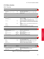
Table 4.2: DTrack2 menu structure overview
45
Chapter 4
DTrack2
4 System setup
4.2.4.2 Menu DTrack2
DTrack2
Shortcut
Configurations
Start/Stop
ARTtrack controller standby
Quit
M
Q
Table 4.3: Menu DTrack2
Configurations It is possible to protect the used configuration by pressing the button
Lock . Then, you will be forced to enter a new password and your configuration is locked.
Z
Please do not forget this password! Otherwise, please contact our
support.
Log settings saves the active configuration to a text file which can be saved on the remote
PC. This function is intended as a simple means for the user to easily create backups of
(personalized) configurations.
Start/Stop Start/Stop measurement.
ARTtrack controller standby Force the SMARTTRACK to go into standby mode with
this command. You can restart the SMARTTRACK by using Wake On LAN. Please refer
to chapter 4.1.5 on page 28 for more details.
Quit Quit DTrack2 frontend software - the active measurement doesn’t have to be
stopped.
4.2.4.3 Menu Settings
Settings
Shortcut
Cameras
Synccard
A.R.T. Radio Info
Tracking
Output
Flystick
Controller
F7
F8
F9
Table 4.4: Menu Settings
46
4.2 DTrack2 frontend software
Cameras This dialogue offers the possibility to adjust the ’flash intensity ’ and to activate the ’modulated flash’. The modulated flash may only be used with active targets. It
is used to synchronize an active target.
DTrack2 is capable of suppressing reflexes (e.g. sunrays on the floor)
in a static way. However, reflex suppression should always be the last option to be considered. If possible try adjusting the cameras in order to minimize reflexes.
Reflex suppression
Z
You should always be aware that reflex suppression results in removing of the area, in which the reflex originated, from the tracking volume.
There are two possibilities to carry out a reflex suppression:
1. Select Calibration → Start Static Reflex Scan for all enabled cameras to make sure
that static reflexes will be suppressed.
2. While measurement is running you may define the areas to be suppressed manually. In the Monitor 2DOF display, right-click on the respective camera window and
enable ’Edit reflex suppression areas’. Alternatively, you may use the shortcut (’E’)
to enable this mode (shown in figure 4.18(a) on page 48).
Within the edit mode you may (also refer to figure 4.18(b) on page 48)
• create new areas,
• delete areas,
• resize areas and
• move areas.
Reflex suppression areas are enabled when you leave the edit mode (by disabling
’Edit reflex suppression areas’) and accept the changes. The single areas defined
are stored in the SMARTTRACK and can be edited each time you enter this mode.
The flash intensity may be changed within an interval of 0 .. 7.
These settings strongly depend on the working area and range. If you have a small working area where you are close to the cameras small flash intensities may be sufficient.
Otherwise, if your working area is a bit further away from the SMARTTRACK (but still
within tracking range) it may be necessary to change to greater flash intensities.
Flash settings
Generally speaking, you should adjust the flash settings in a way that the recognized
markers are coloured in green or yellow.
Do not look directly into the camera from short distance for a longer
period of time!
Please refer to chapter B on page 76 for more information.
47
Chapter 4
• clear regions,
4 System setup
(a) Reflex suppression edit mode
(b) Reflex suppression edit mode help
To be safe, always double-check whether the markers of the target are seen properly by
the cameras. Therefore, please use the Monitor 2DOF view:
• markers coloured in red are characterized by bad circularity, small size or low intensity; this may result in poor tracking quality
• markers coloured in yellow offer a good tracking quality
• markers coloured in green offer a very good tracking quality
Increase the flash intensity until all markers are yellow or green (recommended).
Synccard This dialogue shows the model and the serial number of the synccard. Furthermore, it offers a dropdown list to select the mode of synchronization.
Basically, you can select between internal and external synchronization. The further differentiation is shown in table 4.5.
48
4.2 DTrack2 frontend software
supported synccard mode
field of application
internal generated signal (15 - 60Hz)
external video signal
external video signal, for validated shutter glasses 1
external video signal, for validated shutter glasses, divisor 2 2
active-stereo projection with an
analogue video sync signal (=VGA)
external TTL signal
external TTL signal, for validated shutter glasses 1
external TTL signal, for validated shutter glasses, divisor 2 2
active-stereo projection with a TTL
sync signal
direct settings
advanced custom settings
1
2
predefined settings that should be used with the shutter glasses mentioned in table 4.6
if, additionally, the frequency of the external synchronization signal is greater than 60Hz, this mode
should be used
Table 4.5: Overview of the supported synccard modes
Option
Description
source
configure the type of synchronization to be ’internal’, ’video’,
’ttl’ or ’ttlinv ’
change the frequency in an interval of 10 Hz to 60 Hz (only for
internal synchronization!)
reduce the tracking frequency (only for external synchronization!)
configure the delay between the syncgroups
frequency [Hz]
divisor for external signal
Delay [us]
Brand
Type
RealD
NuVision
XPand
NVidia
Volfoni
CrystalEyes 1, 2, 3, 5
APG6000, APG6100
X103 (with NuVision Long-Range Emitter)
3D Vision Pro (RF sync’ed)
EDGE (with Volfoni or NuVision LR Emitter)
Chapter 4
If you select ’direct settings’ you may use advanced options for configuring the synccard:
Table 4.6: Overview of validated shutter glasses
A.R.T. Radio Info When you are using a Flystick, for example, you will get information
about the used transceiver and the Flystick device itself. The following information is offered:
Description
’Model’
’Serial’
’Version’
’Is free (only for Devices)’
’Is present’
the model of the transceiver or the device respectively
the serial number
the firmware version
the device is not free (= ’no’) if it is assigned to an interaction
device ID
the device or the transceiver is present in the tracking volume
49
4 System setup
By clicking the button Show details you may change the channel the transceiver is transmitting on.
Tracking The number of 6DOF bodies represents the number of targets that should be
tracked. In this context, the number of targets does not include the interaction devices
(e.g. Flystick2, Flystick3). These are completely configurable in separate menus.
However, the maximum total number of bodies that may be used with
the SMARTTRACK includes the calibrated interaction devices (i.e. Flystick)!
i
The two checkboxes which allow more sophisticated settings are described in table 4.7).
Checkbox
Description
’calculation of 3DOF markers’
’automatic start of measurement
after booting’
’automatic restart of measurement after loss of sync signal’ 1
Calculate the coordinates of single markers.
The measurement is started directly after booting
the ATC or ATC/TP.
As soon as DTrack2 acquires the sync signal again
the measurement is started.
1
has been used formerly. Now, activated by default and not changeable.
Table 4.7: Tracking settings - Description of the checkboxes
In the Advanced menu DTrack2 presents an overview of the number of bodies
you have configured before. The name and state (’calibrated’ or ’not calibrated’) of each
body is shown. By default, the name is left blank. You are free to define a name for each
body. Just double-click into the name field and enter a name for the specific body. The
entered name will appear in the data display as soon as you start the measurement.
Advanced
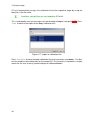
Output The dialogue Output determines the settings of data output via Ethernet. Data
output will be enabled when you tick the checkbox active.
In total, up to 5 UDP channels for DTrack2 data output can be configured. Tick the checkbox this computer to send data to the remote PC you are currently working at. If you want
to send data to any computer within your local network just enter the IP address of the receiver and a port number. In addition, it is possible to define a multicast output. By ticking
this checkbox the UDP data is sent to a group of addresses in the range of 225.0.0.0 to
238.255.255.255.
In order to reduce the data of the UDP output data stream you may set the ’send data
divisor ’ to values from 1 to 10. The numbers have the following meaning:
• 1 .. every frame is transmitted,
• 2 .. every second frame is transmitted,
• ...
50
4.2 DTrack2 frontend software
Identifier
Description
fr
ts
6dcal
6d
3d
6df2
6df
frame counter
timestamp
number of calibrated bodies
6DOF standard body
3DOF marker
Flystick
Flystick (old)
only available if activated in Flystick
settings (→ checkbox ’use old output
format’)
Figure 4.18: Output settings
Table 4.8: Output identifiers
• 10 .. every tenth frame is transmitted.
The mandatory requirement to use this function is that the PC, where DTrack2 is installed, needs to have two separate Ethernet plugs: one for connecting to the SMARTTRACK and one for the respective local network. The DTrack2 frontend reads the data
from the SMARTTRACK and routes it to the local network where the application PC is
connected to.
i
Z
Using this function will cause a short delay during forwarding of the
data.
Do not use this function if the application PC and the ATC are in the
same network!
Please refer to chapter C on page 79 for the format of the data output.
Flystick In the Flystick Settings you can define the number of Flysticks to be used.
Checkbox
Description
’use old output format’
Use the output format of the old Flystick1 (see chapter C on page 79)
Table 4.9: Flystick settings - Description of the checkboxes
Below, there are two more properties which can be configured for Flystick3:
51
Chapter 4
The UDP output data may be routed by DTrack2 by ticking the checkbox act as router
for tracking output. This functionality is especially important for customers where it is not
allowed to connect the SMARTTRACK to their local network due to security reasons.
4 System setup
• sync groups:
Configure your Flystick3 to send out IR flashes for one or more syncgroups (syncgroup #1, syncgroups #1 and #2, . . . ; default = syncgroup #1).
• flash intensity :
Set the flash intensity of the active target of the Flystick3 (default = 3) by moving the
slider.
If you change the number of Flysticks you will immediately recognize entries in the selected Flysticks field. The fields Model, Serial and Port are empty by default.
Make sure that your Flystick is in the available Flysticks list - if necessary, compare the
serial number listed here to the one printed on the battery compartment of the Flystick2 or
on the back cover of the Flystick3. Now, you have to assign your Flystick to the respective
Flystick ID.
Therefore,
• mark the respective Flystick ID,
• mark the desired available Flystick and
• press Select.
Repeat these steps if you want to use another Flystick. Please refer to chapter 5.1 on
page 60 to learn how to install the Flystick2 and refer to chapter 5.2 on page 65 for the
Flystick3.
Controller The menu for the Advanced ARTtrack Controller Settings is divided into two
tabs - Network and Time.
On the Network tab you may change the hostname (not recommended!) and the domain
according to your network guidelines. When the network cable has been plugged into the
SMARTTRACK while booting, the SMARTTRACK is a DHCP client and the checkbox
is ticked. If the network cable is unplugged while booting the SMARTTRACK uses its
default IP address (i.e. 192.168.0.1).
You may also specify IP address, subnet mask , gateway and nameserver as desired.
The MAC address of the SMARTTRACK is printed in the last line for your information
(ethernet-MAC LAN).
On the Time tab you can set the UTC time of the SMARTTRACK . Furthermore, you can
synchronize the UTC (=Universal Time Coordinated) time using NTP (=Network Time
Protocol). NTP is a protocol designed to synchronize the clocks of computers over a network. Tick the checkbox activate NTP and enter hostname or IP address of your server.
If NTP is activated the SMARTTRACK is trying to connect to the NTP server repeatedly
in order to update its clock. The values for ’reachability ’ range between 0% - 100% (typically). They are a measure for the quality of the reachability of the NTP server. Only
NTP servers which are contacted over the internet may provoke some problems. The
quality of the synchronization of the clocks is indicated with ’estimitated precision’ in the
52
4.2 DTrack2 frontend software
unit milliseconds (=ms).
i
Synchronizing with NTP takes quite a long time. Active measurements
won’t be disturbed.
4.2.4.4 Menu Calibration
Calibration
Start static reflex scan for all enabled cameras
Room
Room adjustment
Body
Body adjustment
Shortcut
F5
Shift + F5
F6
Shift + F6
Table 4.10: Menu Calibration
Start static reflex scan for all enabled cameras Scanning for static reflexes allows
searching the measurement volume for unwanted reflexes. Areas are defined around the
visible reflexes, where all reflexes should be suppressed later during measurements.
Be sure to remove all targets from the measurement volume before
starting the scan.
Room Use the room calibration menu to configure your room calibration set concerning
wand length and marker distances. The wand length is printed on a label on the wand please enter the value here.
Figure 4.19: A room calibration set consisting of angle and wand
If you are re-calibrating your room use the checkbox re-calibration in the bottom left corner to indicate it to the tracking system. For more information about room re-calibration
53
Chapter 4
Z
4 System setup
please refer to page 40.
Please refer to chapter 4.2.2 on page 37 for the details on how to perform a room calibration.
Room adjustment In many cases it might be necessary to shift or rotate the default
coordinate system after calibration. The functionality is called from Calibration → Room
adjustment.
(a) ’normal’
(b) ’powerwall’
Figure 4.20: Room adjustment dialogue
The Coarse menu offers the opportunity to manipulate the orientation of the room
coordinate system with just one click. You can define the orientation of two axes - the third
one will be oriented automatically according to the right-hand rule.
Coarse
The offsets in this menu are the coordinates of the new (desired) coordinate system
in the original coordinate system (’Middle of cameras’). Angular corrections are only
allowed up to 20◦ in any direction. The transformation values shift, rotate and scale the
room coordinate system relative to the original one.
Fine
Body Select the body you want to calibrate and tick the checkbox if you want to perform
a re-calibration. Define the coordinate system which can be ’due to body ’, ’due to room’
or ’due to room, zero in marker ’.
54
4.2 DTrack2 frontend software
Type of coordinate system
Description
’due to body ’
the body coordinate system is completely defined by the target
geometry
the body coordinate system is oriented parallel to the room coordinate system. In these cases, the orientation of the body during
body calibration defines the orientation of the body coordinate
system relative to the body. If the body is moved, the orientation
of start position is used.
’due to room’
’due to room, zero in marker ’
The recommended value for the marker quality is ’normal quality ’. If you want to use body
calibration files for calibrating your target, just click Load file(s) and select the appropriate
calibration file(s). By clicking on Save file(s) you can save your body calibrations in separate text files.
Please refer to chapter 4.2.3 on page 40 for the details on how to perform a body calibration.
Body adjustment If you want to manipulate calibration data of rigid bodies this menu
offers the solution. Just select the body you want to manipulate from the drop-down list
which appears at the top of the window. Then, you have the choice between a general or
a special manipulation:
Action
Description
Body position [mm]
Body orientation [deg]
Set origin
translate the body coordinate system along its axes in steps of 1mm
rotate the body coordinate system around its axes
activate a marker in the graphic view by left-clicking with the mouse. The
marker is highlighted and the button Set origin is activated. Pressing
this button translates the origin of the body coordinate system into the
center of the selected marker.
translate the origin of the body coordinate system into the target’s center
of gravity
activate two markers sequentially in the graphic view by left-clicking with
the mouse. The first one is highlighted in white, the second one in grey.
Additionally, the button Set axis is activated. Pressing this button opens
a dialogue to configure the transformation.
pressing this button aligns the body coordinate system in parallel to the
room coordinate system
Set origin to COG
Set axis
Adjust axes to room
Special manipulation
Chapter 4
General manipulation The body coordinate system may be defined in a general manner,
i.e. as desired by the user.
Choose from the following predefined transformations:
• due to body
The body coordinate system is completely defined by the target geometry (see page
42).
• due to room (origin in COG)
55
4 System setup
The coordinate system is rotated in order to be aligned in parallel to the room coordinate system with the origin to be in the center of gravity (COG) (see page 43). In
order to use this function, the checkbox ’use tracked orientation’ has to be ticked.
• due to room (origin in marker)
The coordinate system is rotated in order to be aligned in parallel to the room coordinate system with the origin to be in the marker (see page 43). In order to use this
function, the checkbox ’use tracked orientation’ has to be ticked.
The default view for the calibration data of the rigid body is the ’Graphic view’. Press the
right mouse button and a menu with the following options pops up:
Option
Description
’Small markers’
’Colored markers’
’Long axes’
reduce the size of the markers
show the markers in different colours (default: greyish)
extend the vector arrows of the body coordinate system by infinite
dashed lines
show the center of gravity when changing the orientation of the
view
show the XY plane
show the YZ plane
show the XZ plane
shows the room coordinate system (only available when checkbox ’use tracked orientation’ is ticked)
add a line between two selected markers (option greyed out until
two markers are selected)
remove a line between two selected markers (option greyed out
until line is selected)
switch to the data view
’Show COG’
’Show XY plane’
’Show YZ plane’
’Show XZ plane’
’Show room orientation’
’Add line between markers’
’Delete line between markers’
’Data view’
The View position and View orientation may be changed according to the customer’s
choice. The graphic view may be moved along and/or rotated around the axes. This may
be achieved in two different ways:
1. hold down the "Strg" key and the left (right) mouse button to change the position
(orientation)
2. use the six control dials to adjust position and orientation
To restore the default view, just press ’Reset view’. Tick the ’use tracked orientation’
checkbox if you want to rotate or move the target in the graphic view by rotating or moving
the real target within the measurement volume.
i
56
If you press OK , the changes which have been done for all bodies
will be confirmed (changes are sent to the controller) and the dialogue
closes.
Pressing Apply only results in a confirmation of the changes only for
the currently selected body - the body will directly be reloaded afterwards.
4.2 DTrack2 frontend software
4.2.4.5 Menu Display
Display
Shortcut
Monitor 2DOF
Data
Flystick
Events
F10
Table 4.11: Menu Display
Monitor 2DOF The Monitor 2DOF display essentially is a graphical display of the field
of view of the SMARTTRACK and of the markers that are seen by it. The Monitor 2DOF
display shows two black windows (equivalent to the field of view), with a schematic display
of positions and sizes of all recognized markers. A simple color code signifies the size
and the circularity of the markers (green = very good quality, yellow = good quality, red =
poor quality).
Each marker is either displayed as a circle or as a cross. This indicates the projected size
of the marker on the CCD chip inside the camera (i.e. circle = big marker and cross =
small marker).
In the Monitor 2DOF display it is possible to interact with your mouse as certain functions
are assigned to the mouse buttons.
• middle mouse button:
Click to hide all camera displays except for the one you pointed at. Click once again
and all camera displays are shown.
• right mouse button:
A menu is opened; see table 4.12 for more details.
Data On the left hand side, the Data display shows the 6DOF measurement results of
the position and orientation of the body relative to the room coordinate system. The rotation angles are rotations around the X, Y and Z axis. The mathematical definition can be
found in chapter C on page 79. A simple colour code indicates if the body is tracked or not:
green ...
red
...
white
body is being tracked; tracking data is displayed
body is not being tracked; instead of tracking data dashes are
displayed
... body is not calibrated; columns are left blank
On the right hand side, the 3DOF calculation for single markers or uncalibrated targets
is shown. All recognized single markers that are have not been assigned to a calibrated
57
Chapter 4
• left mouse button:
Click and hold down to move a camera display within the Monitor 2DOF view.
4 System setup
Function
Shortcut
Grid
Cross
Fullscreen
G
C
F
One Camera
Static Reflex Suppression
Start scan for all enabled cameras
Edit reflex suppression areas
E
Shows a grid in the camera display.
Shows a cross in the camera display.
Resizes Monitor 2DOF view to full
screen and back.
Only show the view of the selected
camera.
Initiates a scan for static reflexes. Enabled only if Active is ticked.
Enter the reflex suppression area edit
mode in order to interactively suppress
unwanted reflexes.
Table 4.12: Features of the Monitor 2DOF view
6DOF body are shown here.
Note that the calculation of 3DOF markers has to be activated in Settings → Tracking by
ticking the checkbox. Otherwise, the positions will not be calculated.
Flystick The Flystick display shows the measurement results of the position and orientation of the Flystick. Additionally, the operation of the Flystick buttons and of the joystick
are shown. A simple colour code shows the status of the Flystick:
green
red
blue
white
...
...
Flystick is being tracked; tracking data is displayed
Flystick is not being tracked; instead of tracking data dashes are
displayed
... button is being pressed
... Flystick is not calibrated; columns are left blank
Events The Event display presents the status of the tracking system. It offers feedback
of the operational state concerning errors or warnings. Furthermore, it informs the user
about successful room or body calibrations. Each entry is associated with a timestamp
and date.
Set to default If, for some reason, the appearance of the DTrack2 Frontend got messed
up you may reset all views and the size of the window back to default values. This means
that only the Monitor 2DOF , the Data and the Events displays are shown (refer to figure
4.7 on page 35).
4.2.4.6 Menu About
DTrack2 Offers information about the software version and release date of the DTrack2 frontend software. By clicking on the button Show details you receive a list of every single
software module with the respective software version.
58
4.2 DTrack2 frontend software
About
Shortcut
DTrack2
ARTtrack Controller
ARTtrack Controller Update
What’s this?
Shift + F1
Table 4.13: Menu About
ARTtrack Controller Offers information about the software version and release date
of the DTrack2 backend software. Additionally, name and serial number of the SMARTTRACK are shown.
ARTtrack Controller Update If you update your DTrack2 frontend software it is mandatory that you also update the software of the SMARTTRACK . An assistant will guide you
through the process of the software update. In case you abort the update of the SMARTTRACK software (not recommended!) during this process you can carry it out later. Just
click About → ARTtrack Controller update and follow the instructions of the assistant
given during this process.
Please restart the SMARTTRACK after the assistant finished.
i
Personal settings and configurations (e.g. room and body calibration,
output settings, etc.) will not be lost during update!
Chapter 4
What’s this? By clicking What’s this, you may use our context-sensitive help function
within DTrack2 frontend software. Just use the mouse cursor to point on any feature of
the DTrack2 GUI and you will receive an information with a click on the left mouse button.
59
5 Interaction devices
5.1 Flystick2
The batteries must be removed before shipping the Flystick2, otherwise the radio transmitter could be started by shock or vibration.
Description The Flystick2 is a wireless input device for ART infrared optical tracking
systems.
Figure 5.1: Flystick2
The Flystick2 has a trigger, four buttons and an analogue joystick with an additional button
functionality. All interactions are transmitted wirelessly via a 2.4 GHz ISM radio connection. The software DTrack2 takes up the Flystick2 button & joystick events and correlates
them with the 6DOF output data. Tracking and interaction data are then transmitted to the
application via Ethernet.
i
60
The Flystick2 has no power switch. It is activated automatically within
a few seconds after any button event and is deactivated after several
minutes without usage.
The Flystick2 is tracked via passive markers which are covered by an
acrylic housing. This means that 6DOF tracking is still valid when the
Flystick2 electronics is off.
5.1 Flystick2
Top view
status LEDs
green pulse
yellow pulse
→ button pressed or joystick position successfully transmitted
→ button pressed or joystick position could
not be transmitted
→ low battery, recharge soon
yellow flashing
press the trigger or any button to invoke an interaction which can
be defined in the user application (e.g. drag objects while button
trigger pressed, open a menu dialogue, . . . )
trigger, button
and joystick
Table 5.1: Description of the Flystick2
The output data consists of:
• position and orientation of the Flystick,
• status of buttons and joystick,
• number of used Flysticks.
Please refer to chapter C for more information about the format of the output data.
Control elements The numbering sequence of the buttons is as follows:
• # 1 trigger
• # 2 - # 4 blue buttons, right to left
Chapter 5
• # 5 pressing the joystick
Figure 5.2: Flystick2 control elements
In neutral position the joystick transmits x=0, y=0.
61
5 Interaction devices
• Moving left creates negative x values, moving right positive x values.
• Moving down creates negative y values, moving up positive y values.
• Full extension into any direction creates values of 1.0 or -1.0.
The Flystick2 device provides all functions (buttons, trigger and joystick) simultaneously.
Radio module The Flystick2 uses a radio module in the 2.4GHz band. This band is
standardized internationally and can be used without a license. Range with line of sight
is more than 7m but can be reduced when passing material, e.g. projection screens.
Radio Transceiver2 The USB Radio Transceiver2 has to be plugged in to any free USB
port of the controller before the controller is switched on. During operation, please do not
unplug the USB radio transceiver. This would lead to malfunction of the tracking system.
Please make sure that either the old radio transceiver (connected via
the camera network) or the new USB radio transceiver RT2 is connected to the controller. Connecting both radio transceivers to one
controller would lead to malfunction of the Flystick2 or Flystick3.
Switch on the controller. LED (2) which is framed by a circle (see figure 5.3) lights continuously while controller is booting. When DTrack2 is started, LED (1) which is framed
by a square (see figure 5.3) is switched on and indicates that the radio transceiver was
correctly initialized; LED (2) extinguishes.
During measurement, LED (1) is flashing whenever data is received from or transmitted
to the Flystick. In case of unsuccessful data transmission to the Flystick, LED (2) starts
flashing.
Figure 5.3: USB Radio Transceiver2
Battery pack The battery compartment is at the lower end of the handle. It is fixed with
a single screw which can be opened with the supplied 2mm hexagon key. Remove the
screw and take off the cover of the battery compartment.
Insert the battery pack taking care of the polarity - also note the imprinting "<<INSERT<<"
on the battery pack. Apply the cover of the battery compartment again and fix the screw.
62
5.1 Flystick2
(a) Step 1
(b) Step 2
(c) Step 3
Figure 5.4: Flystick2 - inserting the battery pack
i
The battery pack includes 3 standard AAA rechargeable batteries.
The polarity of the batteries is indicated inside the battery pack. The
rechargeable batteries must be inserted into the battery pack in the indicated polarity.
Dispose used batteries according to governmental regulations (life cycle approximately 2 years).
Risk of explosion if battery is replaced by an incorrect type!
Chapter 5
Charging jack The charging jack is at the bottom of the handle and has to be connected
with the supplied battery charger.
Figure 5.5: Charging the battery of the Flystick2
To prevent damage the battery charger automatically disconnects the Flystick2 electronics. That is why using the Flystick2 with connected charger is not possible.
63
5 Interaction devices
The rechargeable batteries may only be charged with the supplied
charger. To ensure a long life cycle, only recharge the batteries if
they’re empty.
Battery charger A battery charger is supplied with the delivered Flystick2 and must be
used for charging the batteries. For your convenience, the battery pack may remain inside
the Flystick2 for charging. However, during the charging process the Flystick2 cannot be
used.
As soon as the battery pack is connected to the charger, the red LED ("Charge") is
switched on and the green LED ("Ready") starts flashing - the testing cycle is started.
After approximately 1min the testing cycle is over (the green LED extinguishes) and the
charging process starts.
Once the battery pack is fully charged the charger switches off the "Charge" LED, the
"Ready" LED is switched on and the charger goes into trickle charging mode automatically (indicated by a flashing "Ready" LED). Now, the battery pack may be used again.
Please also refer to table 5.2 for an overview of the status LEDs on the battery charger.
Status LED
Colour
Description
Power
red
Charge
Ready
red
green
Discharge
yellow
Button for discharging
yellow
is switched as soon as the charger is connected to
the power plug
is switched on while the charging process is active
is switched on for approx. 2min when the battery
pack is fully charged and starts flashing afterwards
is flashing during the testing cycle
is switched on when the discharging process has
been initialised by pressing the yellow button
starts the discharging process
Table 5.2: Status LEDs quick reference
If you want to discharge the battery pack prior to charging, just press the yellow button
for about 2sec to initiate the discharging process ("Discharge" LED is switched on). This
may take several hours in some cases. However, after this procedure, the battery charger
automatically switches over to the charging process.
Body calibration First, configure the number of Flystick2 you are using: select Settings
→ Flystick and configure the number of Flysticks. You have to assign your Flystick2 to a
’Flystick ID’ by selecting, for example, ’F1’ and selecting your Flystick2 out of the ’available Flysticks’ list.
Now, press Select to finalize the assignment.
i
64
If the ’available Flysticks’ list doesn’t contain your Flystick2 although
it is already present, just press any button of the Flystick2 to register
it at the radio transceiver.
5.2 Flystick3
Then, select Calibration → Body calibration.
In the appearing dialogue the body to be selected is named ’Flystick body 01’. Please
define the orientation of the body coordinate system relative to the body (default setting is
’due to body ’). Make sure that all markers of the Flystick2 are seen by the cameras using
the Monitor 2DOF display which appears in the background.
Press Calibrate and the calibration starts within 5 seconds. Please refer to page 40 for
more information concerning body calibration.
Output settings Please define where the Flystick data has to be sent to. In DTrack2 frontend software, select Settings → Output. You can either select this computer (= remote
PC) or enter an IP address of another computer you want to send data to. By ticking the
checkbox ’6df2’ you can define the Flystick data to be transmitted.
Please refer to chapter 4.2.4.3 on page 50 for more details.
Press Start to start the measurement. In order to see the tracking data you have to enable
the Flystick display by clicking Display → Flystick .
5.2 Flystick3
The batteries must be removed before shipping the Flystick3, otherwise the radio transmitter could be started by shock or vibration.
Chapter 5
Description The Flystick3 is a lightweight input device for ART infrared optical tracking
systems.
(a) active target
(b) passive target
Figure 5.6: Flystick3
65
5 Interaction devices
Top view
status LEDs
green pulse
yellow pulse
→ button pressed or joystick position successfully transmitted
→ button pressed or joystick position could
not be transmitted
→ low battery, recharge soon
yellow flashing
press the trigger or any button to invoke an interaction which can
be defined in the user application (e.g. drag objects while button
trigger pressed, open a menu dialogue, . . . )
trigger, button
and joystick
Table 5.3: Description of the Flystick3
It is equipped with an active1 or passive target, a trigger, three buttons and an analogue
joystick for wireless interaction in a virtual environment. Like with the Flystick2, all interactions are transmitted wirelessly via a 2.4 GHz ISM radio connection. Synchronization
of the Flystick3 is provided wirelessly with a modulated flash by one camera.
The software DTrack2 takes up the Flystick3 button and joystick events and correlates
them with the 6DOF output data. Tracking and interaction data are then transmitted to the
application via Ethernet.
Z
The radio transmission and the active target are switched off after 15
minutes without usage. Press any button to reactivate the Flystick3
and, therefore, tracking.
The output data consists of:
• position and orientation of the Flystick,
• status of buttons and joystick,
• number of used Flysticks.
Please refer to chapter C on page 79 for more information about the format of the output
data.
Control elements The numbering sequence of the buttons is as follows:
• # 1 trigger
• # 2 - # 4 blue buttons, right to left
In neutral position the joystick transmits x=0, y=0.
• Moving left creates negative x values, moving right positive x values.
• Moving down creates negative y values, moving up positive y values.
• Full extension into any direction creates values of 1.0 or -1.0.
The Flystick3 device provides all functions (buttons, trigger and joystick) simultaneously.
1
discontinued in December 2011
66
5.2 Flystick3
Figure 5.7: Flystick3 control elements
Radio Transceiver2 The USB Radio Transceiver2 has to be plugged into any free USB
port of the SMARTTRACK before it is switched on. During operation, please do not
unplug the USB radio transceiver. This would lead to malfunction of the tracking system.
Switch on the SMARTTRACK . LED (2) which is framed by a circle (see figure 5.3) lights
continuously while the SMARTTRACK is booting. When DTrack2 is started, LED (1)
which is framed by a square (see figure 5.3) is switched on and indicates that the radio
transceiver was correctly initialized; LED (2) extinguishes.
During measurement, LED (1) is flashing whenever data is received from or transmitted
to the Flystick. In case of unsuccessful data transmission to the Flystick, LED (2) starts
flashing.
Battery charger A battery charger is supplied with the delivered Flystick3 and must be
used for charging the batteries. For your convenience, the battery pack may remain inside the Flystick3 for charging. During the charging process you may continue using your
Flystick3.
As soon as the battery pack is connected to the charger, the red LED ("Charge") is
switched on. Once the battery pack is fully charged the charger switches off the "Charge"
LED, the green "Ready" LED is switched on. Now, the battery pack may be used again.
The rechargeable batteries may only be charged with the supplied
charger.
67
Chapter 5
Please make sure that either the old radio transceiver (connected via
the camera network) or the new USB radio transceiver RT2 is connected to the SMARTTRACK . Connecting both radio transceivers to
one SMARTTRACK would lead to malfunction of the Flystick2 or Flystick3.
5 Interaction devices
Inserting the battery For inserting the battery into the Flystick3, you have to take off
the back cover completely.
Risk of explosion if battery is replaced by an incorrect type!
Dispose used batteries according to governmental regulations.
Therefore, loosen the four screws using the 2.5mm hexagon key and remove the back
cover.
Place the battery correctly within the cut-out.
Apply the back cover again and tighten the screws carefully.
68
5.2 Flystick3
Wireless synchronization The receiver for the modulated infrared signal which is used
for synchronization is located in the middle of the joint between transparent target and
handpiece (see figure 5.8).
Figure 5.8: Position of the receiver for synchronization
Active targets need synchronization in order to make sure that the IR
LEDs are flashing at the proper time. To ensure wireless synchronization the following points should be observed:
Z
• Note that the synchronization will not work near plasma screens.
Body calibration First, configure the number of Flystick3 you are using: select Settings
→ Flystick and configure the number of Flysticks. You have to assign your Flystick3 to a
’Flystick ID’ by selecting, for example, ’F1’ and selecting your Flystick3 out of the ’available Flysticks’ list.
Now, press Select to finalize the assignment.
i
If the ’available Flysticks’ list doesn’t contain your Flystick3 although
it is already present, just press any button of the Flystick3 to register
it at the radio transceiver.
Then, select Calibration → Body calibration.
In the appearing dialogue the body to be selected is named ’Flystick body 01’. Please
define the orientation of the body coordinate system relative to the body (default setting is
’due to body ’). Make sure that all markers of the Flystick3 are seen by the cameras using
the Monitor 2DOF display which appears in the background.
Press Calibrate and the calibration starts within 5 seconds. Please refer to page 40 for
more information concerning body calibration.
69
Chapter 5
• If two or more tracking systems using wireless synchronization
are in the same room, then external synchronization of the systems might be necessary (e.g. at tradeshows).
5 Interaction devices
Output settings Please define where the Flystick data has to be sent to. In DTrack2 frontend software, select Settings → Output. You can either select this computer (= remote
PC) or enter an IP address of another computer you want to send data to. By ticking the
checkbox ’6df2’ you can define the Flystick data to be transmitted.
Please refer to chapter 4.2.4.3 on page 50 for more details.
Press Start to start the measurement. In order to see the tracking data you have to enable
the Flystick display by clicking Display → Flystick .
70
6 General Information
6.1 Service
It is recommended to maintain the equipment every three years. If you experience any
problems please do not hesitate to contact our support.
Never try to repair anything yourself!!
Opening the equipment implies risks for health and environment as well as loss of warranty and liability.
6.2 Cleaning of the equipment
Only the housing of the cameras may be cleaned. Before cleaning shut down the system
and disconnect the power cords.
Never use water or any chemicals. Just use a dry, lint-free and antistatic tissue like lenscleaners for optical equipment.
Do not open the housings!
Opening the housings implies risk for health and environment, as well as loss of warranty
and liability.
Hardware ART warrants the hardware to be free from defects in workmanship and material under normal use and service and in its original, unmodified condition, for a period
of 24 months from the time of purchase. The time of purchase is defined as the day when
the end-user takes possession of the equipment. If ART or any company authorized by
ART installs the system, the time of purchase is the time of the first installation.
In case of defects during the warranty period, ART will repair or replace any defective
parts. Replaced parts become property of ART .
Software Software supplied either on the tracking-PC or in cameras is furnished on a
tested "As Is" basis. ART explicitly does not warrant that the software is error (bug) free.
71
Chapter 6
6.3 Warranty and liability
6 General Information
If the users detect bugs, ART will provide a workaround or bug fix as soon as possible
after the notification.
Liability ART products are not authorized for use in any circumstances where human
life might be endangered by malfunction, measurement errors or interrupted operation of
the system without written approval of a managing director of ART .
It is the user’s sole responsibility to check the results of the measurement data and to
protect any consecutive system against malfunction, measurement errors or interrupted
operation of the systems supplied by ART . Under no circumstances ART can be held
liable for consequential damages or incidental costs, including production downtimes,
whether arising from measurement errors, interrupted operation or any other malfunction
of the system.
Warranty restrictions All warranty and liability is void, if the system
• is not operated according to the manual,
• shows damages or signs of abuse,
• has been opened by non-authorized people (non-members of ART and companies
not authorized by ART ),
• has been modified by the user or any third party,
• has not been used according to the specifications of this manual.
72
A Technical specifications
The specifications are subject to change without notice.
Appendix A
Z
A.1 SMARTTRACK
Power supply
Nominal voltage
Maximal current
Maximal power
Ext. power supply
12V
0.5A
6W
12.2V / 3A / 40W
Protection category
Ext. power supply
Camera
I
III
Interface connectors
data
synchronization
power
RJ45
BNC
external
Operating conditions
Temperature
Relative humidity
Cooling system
0 .. 40◦ C
5 .. 50%
non-condensing
active (fan)
Dimensions
Length
Width
Height
Weight
420mm
15mm
54mm
1470g
Performance
Frame rate
max. 60fps (adjustable)
IR flash
850nm
Max. tracking distance with 12mm passive markers (F .. focal length in mm).
@ F = 2.1mm
2.5m
Maximum number of 6DOF targets (simultaneously)
@ 60fps
4
Field of view (FoV for each lens, horizontal × vertical)
@ F = 2.1mm
100◦ × 84◦
73
A Technical specifications
A.2 Flysticks
Flystick2
Flystick3
Rechargeable battery
3 standard AAA batteries
Continuous operation1
Battery charging duration
Operation possible with connected charger
at least 10 hours
lithium battery (850mAh / 3.7V)
integrated in the handheld
at least 8 hours
no
yes
USB
at least 7m
USB
at least 7m
IEEE 802.15.4
2.4 GHz
1
IEEE 802.15.4
2.4 GHz
1
0 .. 40◦ C
5 .. 50%, non-condensing
0 .. 40◦ C
5 .. 50%, non-condensing
Target type
passive markers
Tracking range
(@ 3.5mm focal length)
Weight
Size
approx. 4m
passive or active markers
(IR-LEDs @ 880nm)
approx. 4.5m
250g
220mm x 180mm x 100mm
120g
245m x 90mm x 75mm
Power supply
USB transmitter
Connection to the PC
Radio range
(depending on setup location,
e.g. walls)
Radio module
Type ID
Frequency
Transmission power
Operating conditions
Operating temperature
Relative humidity
General features
1
74
only valid for new batteries
A.3 Overall system
A.3 Overall system
Operating conditions
Temperature
Relative humidity
0 .. 40◦ C
5 .. 50%, non-condensing
Compatible shutter glasses
×
×
×, radio synchronization
×
×
×
×
×, with Volfoni or NuVision Long-Range Emitter
×, with NuVision Long-Range Emitter
Appendix A
NuVision APG6000
NuVision APG6100
NVidia 3D Vision Pro
RealD CE1
RealD CE2
RealD CE3
RealD CE4
RealD CE5
Volfoni EDGE
XPand X103
DTrack2 frontend software
System requirements
- Free disk space
- Processor
- RAM
Operating systems
Settings firewall (remote PC)
- used ports
≥ 200MB
Intel: ≥ P4 2GHz
AMD: ≥ K6 1.6Ghz
≥ 1GB
Windows XP 32/64 Bit
Windows 7 64 Bit
Linux openSUSE 11.3 32/64 Bit
ubuntu 10.04 32/64 Bit
50105 (for UDP & TCP)
50110 (for UDP)
75
B Radiation Protection for
SMARTTRACK
B.1 Used Instructions
All calculations refer to German DIN EN 60825-1: "Safety of laser products" ("Sicherheit
von Laser-Einrichtungen"), which is correspondingly applied to noncoherent illumination
by LEDs. Derived safety instructions correspond to "Durchführungsanweisung zur UVV
Laserstrahlung" ("Instructions for using UVV laser radiation") of German "Hauptverband
der gewerblichen Berufsgenossenschaften" ("Association of commercial and industrial
workers compensation insurance carriers") (October 1995).
B.2 Classification of the LED Flash
The wave length of the LEDs (medium wave length) is in the near infrared at 850nm. It is
an expanded source having an area of about 37mm x 37mm.
The emitted radiation is divergent (in contrast to laser radiation). The radiation source is
pulsed repeatedly. According to the above-named instructions, three cases have to be
considered when using repeatedly pulsed or modulated laser sources of this wave length.
Safety instructions will then be determined by the biggest limitation found in these cases:
• exposure of radiation by one single impulse
• average radiation intensity
• radiation by one single impulse with a correction factor for a sequence of impulses.
The intensity of divergent radiation depends on the distance between observer (his eyes
respectively) and radiation source.
B.3 Maximum Permitted Exposure of Radiation (MPER)
This chapter shows the "maximum permitted exposure of radiation" (MPER) for the above
mentioned cases.
Exposure of Radiation by One Single Impulse Partial result: the exposure of radiation
is lower than the MPER value, when ensuring a distance of more than 10cm between IR
flash and eye.
76
B.4 Resulting Safety Instructions
Average Radiation Intensity Partial result: the exposure of radiation is lower than the
MPER value, when ensuring a distance of more than 10cm between IR flash and eye.
Radiation by One Single Impulse with a Correction Factor for a Sequence of Impulses Partial result: the limitations derived from this case are the most significant.
They determine the below listed safety instructions.
B.4 Resulting Safety Instructions
The values of minimum necessary distances to the external flash are
pretty high. During setup, do NOT look into the flash or, better, switch
off the external flash!
However, the external flashes are typically mounted behind a projection screen which reduces the radiation intensity by a certain factor
depending on the type of screen used. Therefore, only the values for
the external flash itself are stated.
Figure B.1: SMARTTRACK : Minimum necessary distance at 60Hz and different flash
intensities
Example (see figure B.1): Setting a flash intensity of 7 with a duration of exposure of 1
hour, the minimum distance between observer’s eye and the SMARTTRACK has to be at
77
Appendix B
The following diagrams show the minimum necessary distance between IR flash and eyes
to fulfill the exposure limitations according to chapter B.3 on page 77.
B Radiation Protection for SMARTTRACK
least 14cm.
Usually the cameras are mounted e.g. at the ceiling of a room; so during normal operation an observer never gets closer to the cameras than the minimum distance. During
mounting of the IR cameras attention should be payed to switch on the cameras only for
adjustment and not to expose service technicians or other people at a not allowed amount.
If inappropriate use of the IR cameras is possible, employees have to
be instructed accordingly and warning notices have to be attached at
the tracking cameras.
78
C Technical Appendix
C.1 Definition of Coordinates and Rotations
C.1.1 Room Calibration
Type
longer arm
shorter arm
’normal’
’powerwall’
’powerwall standing’
+X axis
+X axis
-X axis
+Y axis
-Z axis
+Y axis
For example, a room calibration of type ’normal’ would result in a coordinate system like the
following:
1. The marker located in the crossing point of the two arms is defining the origin of the coordinate system.
2. The longer arm of the calibration tool defines the +X axis.
3. The shorter arm of the calibration tool defines the +Y axis. (i.e., the tool markers define the
X/Y plane.)
4. The Z axis is added in order to give a right-handed coordinate system.
C.1.1.1 Room Adjustment
DTrack2 allows to modify the room coordinate system by specifying these seven values:
• lx , ly , lz for a translational offset (denoted x, y, z in the GUI),
• η, θ, φ for a rotation (denoted rx, ry, rz in the GUI).
• s for a scaling factor.
These offsets are defined as a shift and/or rotation and/or scaling of the room coordinate system
relative to the original one. Mathematically a point ~xorig in the original room is transformed into a
point ~xmod in the modified room coordinate system by:
~xmod = (RT · ~xorig − ~l) · s
where the rotation matrix R is calculated from η, θ and φ like defined in section C.1.3.
79
Appendix C
The calibration angle defines origin and axes of the coordinate system. This can be done in three
different ways:
C Technical Appendix
C.1.2 Body Calibration
During the body calibration DTrack2 is fixing a local coordinate system (body coordinate system)
for each rigid body. Both coordinate systems define the later 6DOF output (see chapter C.1.3 on
page 81). The calibration can be done in three different ways (to be selected in the menu Calibrate
/ Body of the body calibration):
C.1.2.1 Definition of the Coordinates by the Body itself
Body calibration setting due to body :
The body coordinate system is fixed by the markers of the rigid body according to a set of rules:
1. Search the biggest distance between two markers of the rigid body. These two markers (#1
and #2) will define the X axis.
2. Search for a third marker (#3) that has the smallest distance to one of the two markers #1
and #2. The marker that has smallest distance to marker #3 becomes marker #1. It will
define the coordinate origin. The other marker will be #2. The positive X axis is directed
from marker #1 to marker #2.
3. Marker #3 defines the X/Y plane, together with markers #1 and #2. Marker #3 has a positive
Y coordinate.
4. The Z axis is already defined by these rules, resulting in a right-handed coordinate system.
C.1.2.2 Definition of the Coordinates by the Room Coordinate System, with Origin
in the Center of the Markers
Body calibration setting due to room:
The origin of the body coordinate system is set to the center (center of gravity) of all markers
building the rigid body. The axes of the body coordinate system are parallel to the axes of the
room coordinate system in the beginning of the body calibration.
I.e., the result of a body calibration will depend on the angular position of the target during calibration. A 6DOF measurement, following calibration without having moved the body, will give the
angular coordinates 0◦ / 0◦ / 0◦ .
If the target was moved during calibration, the angular position of the target at the beginning of the
calibration will be taken.
C.1.2.3 Definition of the Coordinates by the Room Coordinate System, with Origin
in a Marker
Body calibration setting due to room (zero in marker):
A combination of the first two methods. The direction of the axes of the body coordinate system
will be set parallel to the room coordinate system in the moment of body calibration - like done
with setting due to room. The origin of the body coordinate system is given by one marker of the
body, according to the rules given for setting due to body .
80
C.1 Definition of Coordinates and Rotations
C.1.3 6DOF Results
Position and Orientation
Position and orientation of a target are expressed by an affine transformation (~s, R) that transforms
a vector ~x from the body coordinate system to the room coordinate system:
~xroom = R · ~xbody + ~s
I.e., the coordinates ~s give the position of the origin of the body coordinate system (marker #1 or
center of gravity, as described above), measured in room coordinates.
The 3 × 3 rotation matrix R describes the rotation part of the transformation. The columns of the
matrix R are the axes (X, Y, Z) of the body coordinate system, expressed in room coordinates.
Description by Rotation Angles
The rotation matrix can be replaced by three consecutive rotations Ri (χ) (rotation angle χ, rotation
axis i). The angles, as given in the DTrack2 data output, are defined by the equation:
R = Rx (η) · Ry (θ) · Rz (φ)
Appendix C
Expressed in trigonometric functions, that means:
cos φ cos θ
− sin φ cos θ
sin θ
R = sin φ cos η + cos φ sin θ sin η cos φ cos η − sin φ sin θ sin η − cos θ sin η
sin φ sin η − cos φ sin θ cos η cos φ sin η + sin φ sin θ cos η cos θ cos η
Note that per definitionem the angles can only have the values:
−180◦ ≤ φ ≤ 180◦ , −90◦ ≤ θ ≤ 90◦ , −180◦ ≤ η ≤ 180◦
Z
Note: rotation angles can show strange behaviour at certain orientations. At
particular orientations close to θ = ±90◦ the other two angles can experience
large odd-looking changes.
When connecting DTrack2 to an application, often problems appear caused by different definitions
of rotation angles. To avoid that, we recommend to use rotation matrices.
C.1.4 3DOF Data
Besides the tracking of 6DOF bodies, DTrack2 is able to calculate the coordinates of single markers, i.e. markers that can not be recognized as part of a rigid body. The output values are the
coordinates of these markers, measured in room coordinates.
In some situations, a rigid body within the measurement volume is (temporarily) not correctly
recognized by the software. In these cases, its markers appear as 3DOF objects.
3DOF markers are tracked (as long as possible) and labeled with an ID number. When a 3DOF
marker vanishes (or is recognized as part of a 6DOF body), its ID number will not be used any
more, as long as the tracking is active.
C.1.5 Flystick devices
DTrack2 is supporting the following input devices:
• Flystick2 and
81
C Technical Appendix
• Flystick3.
Each of the afore mentioned devices is equipped with buttons (4 - 8) and a small joystick. Input
transactions are transmitted wirelessly to the controller and added to the 6DOF tracking result of
the Flystick body.
There are two types of output formats available, called 6df and 6df2 (details see chapter C.2.4 on
page 85 and chapter C.2.5 on page 86); they differ in the number of carried input controls. Only
the newer 6df2 format is capable of processing analogue values (or controllers) as produced by a
joystick. Both formats use the same order of buttons (details see below):
Output Format
Number of Buttons
Order of Buttons
Number of Controllers
6df
6df2
8 (fix)
device dependent
“right to left”
“right to left”
—
device dependent
C.1.5.1 Flystick2
Each Flystick2 is equipped with six switches (buttons) and a small joystick, that produces two
analogue values, one for horizontal and one for vertical movement. When using the old output
format 6df, the joystick values are transferred into hat switch actions; two of the buttons cannot be
accessed.
Switch
labelled as
(in figure C.1)
6df Output
6df2 Output
front switch (yellow)
outer right switch on backside (blue)
inner right switch on backside (blue)
inner left switch on backside (blue)
outer left switch on backside (blue)
switch on joystick (yellow)
joystick (yellow) to the left
joystick (yellow) to the right
joystick (yellow) up
joystick (yellow) down
id 0
id 1
id 2
id 3
id 4
id 5
–
–
–
–
code 01 (hex)
code 02 (hex)
code 04 (hex)
code 08 (hex)
–
–
code 20 (hex)
code 80 (hex)
code 40 (hex)
code 10 (hex)
button code 01 (hex)
button code 02 (hex)
button code 04 (hex)
button code 08 (hex)
button code 10 (hex)
button code 20 (hex)
first controller up to 1.0
first controller up to −1.0
second controller up to 1.0
second controller up to −1.0
C.1.5.2 Flystick3
Each Flystick3 is equipped with four switches (buttons) and a small joystick, that produces two
analogue values, one for horizontal and one for vertical movement. When using the old output
format 6df, the joystick values are transferred into hat switch actions.
82
Switch
labelled as
(in figure C.1)
6df Output
6df2 Output
bottom switch (yellow)
top right switch (blue)
top middle switch (blue)
top left switch (blue)
joystick (yellow) to the left
joystick (yellow) to the right
joystick (yellow) up
joystick (yellow) down
id 0
id 1
id 2
id 3
–
–
–
–
code 01 (hex)
code 02 (hex)
code 04 (hex)
code 08 (hex)
code 20 (hex)
code 80 (hex)
code 40 (hex)
code 10 (hex)
button code 01 (hex)
button code 02 (hex)
button code 04 (hex)
button code 08 (hex)
first controller up to 1.0
first controller up to −1.0
second controller up to 1.0
second controller up to −1.0
C.2 Output of Measurement Data via Ethernet
(a) Flystick2
(b) Flystick3
Figure C.1: Allocation of ID number to the Flystick buttons
DTrack2 uses ethernet (UDP/IP datagrams) to send measurement data to other applications. The
IP address and the port of the application (and the computer it runs on) can be configured in
Settings → Output.
Each datagram carries all the results of a single measurement, coded in ASCII format. One datagram is sent after each measurement of the cameras, i.e. following the synchronization frequency.
The ’send data divisor ’ in Settings → Output offers the possibility to decrease the data output
frequency (foutput = fsync /ddivisor ).
i
All data are given in units millimeter (mm) or angular degree (deg / ◦ ).
ART provides free sample source code (‘DTrack2SDK’, in C++) to receive and parse the output
data. Please contact ART to get it.
A UDP datagram in ASCII format contains several lines separated by CR/LF (hex 0D 0A). Each
line carries data of a specific type and starts with an identifier. In Settings → Output you may
configure which lines or data types should be included in the output:
Identifier
Type of data
enable/disable in
fr
ts
6dcal
6d
3d
6df/6df2
frame counter
timestamp
additional informations
standard bodies (6DOF)
additional markers (3DOF)
Flysticks (6DOF + buttons)
always enabled
Settings → Output
Settings → Output
Settings → Output
Settings → Output
Settings → Output
(’ts’)
(’6dcal’)
(’6d’)
(’3d’)
(’6df / 6df2’)
C.2.1 Frame Counter
Identifier fr.
This line is always the first one. It carries a frame counter (counting with synchronization frequency).
83
Appendix C
C.2 Output of Measurement Data via Ethernet
C Technical Appendix
Example:
fr 21753
C.2.2 Timestamp
Identifier ts.
A timestamp can be added to each datagram. It shows the time at the measurement of this frame,
i.e. the time when the infrared flash of the cameras is fired. The timestamp uses the internal clock
of the controller, giving back the seconds (with an accuracy of 1µs) since 00:00 UTC1 (midnight).
This implies that the timestamp value is reset to zero when passing midnight (UTC)!
The timestamp typically shows an accuracy of better than ∆terr ∼ ±0.01ms
with a Synccard2 (used in ARTTRACK systems). With a SynccardTP (used in
TRACKPACK systems) one can only expect an accuracy of ∆terr ∼ ±0.5ms.
i
Example:
ts 39596.024831
C.2.3 Standard 6DOF Bodies
Identifier 6d.
Measurement data of all tracked standard 6DOF bodies (i.e. all 6DOF bodies except Flysticks,
Measurement Tools . . . ). Bodies, that are not tracked by the system at that moment, don’t appear
in the output.
• The first number gives the number of tracked bodies (less or equal to the number of calibrated bodies).
• The data of each tracked body show up in blocks (three consecutive []) like:
[id qu][sx sy sz η θ φ][b0 b1 b2 b3 b4 b5 b6 b7 b8 ]
They contain:
1. ID number (id, starting with 0), quality value (qu, unused),
2. Position (si ), orientation angles (η θ φ) and
3. Rotation matrix (bi ) of the Body’s orientation.
All numbers are separated by spaces (hex 20). Nine values b0 . . . b8 form the rotation matrix
R:
b0 b3 b6
R = b1 b4 b7
b2 b5 b8
To avoid problems with different definitions of the angles, we recommend to only use rotation
matrices.
1
Coordinated Universal Time = Greenwich Mean Time
84
C.2 Output of Measurement Data via Ethernet
Example (one line):
6d 1 [0 1.000][326.848 -187.216 109.503 -160.4704 -3.6963
-7.0913][-0.940508 -0.339238 -0.019025 0.333599 -0.932599 0.137735
-0.064467 0.123194 0.990286]
C.2.4 Flysticks
Identifier 6df2.
Z
Note: this format version replaces the older 6df format (see C.2.5). Use it
whenever possible.
The newer format for Flysticks is quite similar to the format of standard 6DOF bodies. It provides
tracking data for all Flysticks and other ART radio devices (see C.1.5):
• The first number after the identifier 6df2 gives the number of defined (i.e. calibrated) Flysticks.
• The second number gives the number of Flystick data, that are following in the line.
• The data of each Flystick show up in blocks (four consecutive []), like:
The four blocks contain:
1. ID number (id, starting with 0), quality value (qu, see below) and the number of available buttons and controllers (nbt and nct).
2. Position of the Flystick (si ).
3. Orientation of the Flystick, given as rotation matrix (bi , like standard bodies).
4. Status of buttons (bti , see below) and controllers (cti , see below).
• The quality (qu) can (so far) just get the values 1.000 or −1.000. −1.000 means that the
target of the Flystick is not visible at the moment. Even in that case a Flystick appears in the
output data. Then dummy values are used for position (zero) and orientation (zero matrix!).
Informations about buttons and controllers are valid as long as the wireless transmission is
active.
• When buttons of the Flysticks are pressed the (decimal) numbers bti change. They are
coded binary (i.e. switch 1 activated = bit 0 set, switch 2 activated = bit 1 set, . . . ) with a
maximum of 32 buttons per bti number.
Z
Note that the number of bti numbers in the block can vary with different
Flystick hardware! If the device isn’t equipped with buttons, the output
won’t contain any bti number!
• Controller elements are transferred into floating point numbers cti , reaching from −1.00 to
1.00. In the output line they follow the button informations (one number for each controller).
Note that the number of cti numbers in the block can vary with different
Flystick hardware! If the device isn’t equipped with controller elements,
the output won’t contain any cti number!
Z
85
Appendix C
[id qu nbt nct][sx sy sz ][b0 b1 b2 b3 b4 b5 b6 b7 b8 ][bt0 ... ct0 ct1 ...]
C Technical Appendix
Example (one line) for two devices, one Flystick2 (ID 0) and one Flystick1 (ID 1):
6df2 2 2 [0 1.000 6 2][-228.992 270.818 92.561][0.758006 -0.652230 0.004807 -0.651759
-0.757133 0.044271 -0.025236 -0.036691 -0.999008][5 0.13 -1.00] [1 -1.000 4 2][0.000
0.000 0.000][0.000000 0.000000 0.000000 0.000000 0.000000 0.000000 0.000000 0.000000
0.000000][1 1.00 0.00]
C.2.5 Flysticks (Old Format)
Identifier 6df.
Z
i
Note: supported just for compatibility. It is recommended to use the newer
Flystick format 6df2 (see chapter C.2.4 on page 85) whenever possible.
Refer to chapter C.1.5.1 on page 82 to find out which buttons of the Flystick2
are NOT transmitted when using the old output format 6df.
This older format for Flysticks is quite similar to the format of standard 6DOF bodies:
• The first number gives the number of defined Flysticks.
• The data of each Flystick show up in blocks (three consecutive []) like:
[id qu bt][sx sy sz η θ φ][b0 b1 b2 b3 b4 b5 b6 b7 b8 ]
They contain:
1. ID number (id, starting with 0), quality value (qu, see below) and button information
(bt, see below),
2. Position (si ) and orientation angles (η θ φ) and
3. Orientation (bi ) of the Flystick.
• The quality (qu) can (so far) just get the values 1.000 or −1.000. −1.000 means that the
target of the Flystick is not visible at the moment. Even in that case a Flystick appears in the
output data. Then dummy values are used for position (zero) and orientation (zero matrix!).
Informations about buttons are valid as long as the wireless transmission is active.
• When buttons of the Flysticks are pressed the (decimal) number bt changes. It is coded
binary (i.e. switch 1 activated = bit 0 set, switch 2 activated = bit 1 set, . . . ).
Example (one line):
6df 1 [0 1.000 2][261.103 116.520 41.085 19.6522 -57.3530 116.5992]
[-0.241543 0.968868 -0.054332 -0.482366 -0.168461 -0.859619
-0.842010 -0.181427 0.508039]
C.2.6 Additional 3DOF Markers
Identifier 3d.
The format of additional markers (all markers that don’t belong to a 6DOF object) looks like a
reduced format of standard bodies:
• The first number is the number of tracked additional markers.
86
C.2 Output of Measurement Data via Ethernet
• Blocks (two consecutive []) follow for each marker:
[id qu][sx sy sz ]
They contain ID number (id, starting with 1) and a quality value (qu, still unused), and the
position (si ).
Example (one line):
3d 6 [79 1.000][210.730 -90.669 -108.554] [83 1.000][61.235 -165.625
3.217] [87 1.000][123.633 -107.836 0.110] [88 1.000][212.383 -133.640
77.199] [90 1.000][326.455 -187.055 109.589] [91 1.000][303.185
-239.771 114.861]
C.2.7 Additional Informations
Identifier 6dcal.
6dcal 3
Z
Note that this number does not include all calibrated bodies. In particular, it
counts the calibrated bodies that show up in the output lines 6d, 6df and 6dmt.
87
Appendix C
Optionally, the number of the calibrated bodies (not only of the tracked ones) can be included in a
data set. This is done within an additional line like:
List of Figures
2.1 Principle of optical tracking (stereo vision) . . . . . . . . . . . . . . . . . . . 11
3.1 Angular range of visibility . . . . . . . . . . . . . . . . . . . . . . . . . . . . 15
22
23
28
29
33
34
35
35
36
37
38
4.13
4.14
4.15
4.16
4.17
4.18
4.19
4.20
SMARTTRACK . . . . . . . . . . . . . . . . . . . . . . . . . . . . . . . . .
Attaching the T-piece to the SMARTTRACK . . . . . . . . . . . . . . . . .
Welcome screen of DTrack2 with Wake On LAN option . . . . . . . . . . .
Wake On LAN progress bar . . . . . . . . . . . . . . . . . . . . . . . . . . .
Welcome screen of DTrack2 . . . . . . . . . . . . . . . . . . . . . . . . . .
ARTTRACK Controller Selection . . . . . . . . . . . . . . . . . . . . . . . .
Graphical user interface of DTrack2 . . . . . . . . . . . . . . . . . . . . . .
Visualization of the synchronization frequency decrease . . . . . . . . . . .
Monitor 2DOF view menu (e.g. camera 1) . . . . . . . . . . . . . . . . . . .
Origin of the room coordinate system (default) . . . . . . . . . . . . . . . .
Room calibration settings (e.g. RCS 410) . . . . . . . . . . . . . . . . . . .
Marker distances (including numbering) on the angle and definition of room
coordinate system . . . . . . . . . . . . . . . . . . . . . . . . . . . . . . . .
Room calibration process . . . . . . . . . . . . . . . . . . . . . . . . . . . .
Room re-calibration dialogue . . . . . . . . . . . . . . . . . . . . . . . . . .
Body calibration dialogue . . . . . . . . . . . . . . . . . . . . . . . . . . . .
Defining the target coordinate system . . . . . . . . . . . . . . . . . . . . .
Import of calibration files . . . . . . . . . . . . . . . . . . . . . . . . . . . . .
Output settings . . . . . . . . . . . . . . . . . . . . . . . . . . . . . . . . . .
A room calibration set consisting of angle and wand . . . . . . . . . . . . .
Room adjustment dialogue . . . . . . . . . . . . . . . . . . . . . . . . . . .
5.1
5.2
5.3
5.4
5.5
5.6
5.7
5.8
Flystick2 . . . . . . . . . . . . . . . . . . . .
Flystick2 control elements . . . . . . . . . .
USB Radio Transceiver2 . . . . . . . . . . .
Flystick2 - inserting the battery pack . . . .
Charging the battery of the Flystick2 . . . .
Flystick3 . . . . . . . . . . . . . . . . . . . .
Flystick3 control elements . . . . . . . . . .
Position of the receiver for synchronization .
60
61
62
63
63
65
67
69
4.1
4.2
4.3
4.4
4.5
4.6
4.7
4.8
4.9
4.10
4.11
4.12
.
.
.
.
.
.
.
.
.
.
.
.
.
.
.
.
.
.
.
.
.
.
.
.
.
.
.
.
.
.
.
.
.
.
.
.
.
.
.
.
.
.
.
.
.
.
.
.
.
.
.
.
.
.
.
.
.
.
.
.
.
.
.
.
.
.
.
.
.
.
.
.
.
.
.
.
.
.
.
.
.
.
.
.
.
.
.
.
.
.
.
.
.
.
.
.
.
.
.
.
.
.
.
.
.
.
.
.
.
.
.
.
.
.
.
.
.
.
.
.
.
.
.
.
.
.
.
.
.
.
.
.
.
.
.
.
.
.
.
.
.
.
.
.
38
40
41
42
42
44
51
53
54
B.1 SMARTTRACK : Minimum necessary distance at 60Hz and different flash
intensities . . . . . . . . . . . . . . . . . . . . . . . . . . . . . . . . . . . . . 77
C.1 Allocation of ID number to the Flystick buttons . . . . . . . . . . . . . . . . . 83
88
List of Tables
1.1 Symbols and their meaning . . . . . . . . . . . . . . . . . . . . . . . . . . .
8
4.1
4.2
4.3
4.4
4.5
4.6
4.7
4.8
4.9
4.10
4.11
4.12
4.13
Options for coordinate system definition . . . . .
DTrack2 menu structure overview . . . . . . . .
Menu DTrack2 . . . . . . . . . . . . . . . . . . .
Menu Settings . . . . . . . . . . . . . . . . . . .
Overview of the supported synccard modes . . .
Overview of validated shutter glasses . . . . . .
Tracking settings - Description of the checkboxes
Output identifiers . . . . . . . . . . . . . . . . . .
Flystick settings - Description of the checkboxes
Menu Calibration . . . . . . . . . . . . . . . . . .
Menu Display . . . . . . . . . . . . . . . . . . . .
Features of the Monitor 2DOF view . . . . . . . .
Menu About . . . . . . . . . . . . . . . . . . . . .
.
.
.
.
.
.
.
.
.
.
.
.
.
.
.
.
.
.
.
.
.
.
.
.
.
.
.
.
.
.
.
.
.
.
.
.
.
.
.
.
.
.
.
.
.
.
.
.
.
.
.
.
.
.
.
.
.
.
.
.
.
.
.
.
.
.
.
.
.
.
.
.
.
.
.
.
.
.
.
.
.
.
.
.
.
.
.
.
.
.
.
.
.
.
.
.
.
.
.
.
.
.
.
.
.
.
.
.
.
.
.
.
.
.
.
.
.
.
.
.
.
.
.
.
.
.
.
.
.
.
.
.
.
.
.
.
.
.
.
.
.
.
.
.
.
.
.
.
.
.
.
.
.
.
.
.
.
.
.
.
.
.
.
.
.
.
.
.
.
.
.
.
.
.
.
.
.
.
.
.
.
.
.
.
.
.
.
.
.
.
.
.
.
.
.
39
45
46
46
49
49
50
51
51
53
57
58
59
5.1 Description of the Flystick2 . . . . . . . . . . . . . . . . . . . . . . . . . . . 61
5.2 Status LEDs quick reference . . . . . . . . . . . . . . . . . . . . . . . . . . 64
5.3 Description of the Flystick3 . . . . . . . . . . . . . . . . . . . . . . . . . . . 66
89
Appendix C
3.3 Standard targets overview . . . . . . . . . . . . . . . . . . . . . . . . . . . . 21
Index
body adjustment, 55
calibration
body calibration, 41, 54
calibration file, 43, 55
room calibration, 37, 53
room re-calibration, 40
center of gravity, 56
coded flash, 16
configuration management, 46
controller, 25
Data Display, 34
data output, 50
DHCP, 52
Event Display, 34
field of view (FoV), 35, 73
flash intensity, 47
infrared optical tracking system, 11
interaction device
Flystick2, 51, 60
Flystick3, 51, 65
IP address, 26
liability, 71
line of sight, 62
MAC address, 29, 52
marker
active marker, 14
big active flat marker, 15
big active spherical marker, 15
passive marker, 13
measurement volume, 39
Monitor 2DOF, 34, 57
motion capture, 21
radio module, 62
90
reflex suppression
automatic, 47
manual, 47
remote PC, 31
retro reflector, 14
rigid body, 17
room adjustment, 54
room calibration set, 37
send data divisor, 50
service and support, 71
Settings, 46
shutter glasses (validated), 49
SMARTTRACK, 22, 31, 52
software
DTrack2, 31, 46
standby mode, 46
static reflex scan, 53
synchronization
active marker synchronization, 15
external synchronization, 48
internal synchronization, 48
synchronization signal, 25
targets, 17
timestamp, 51, 84
tracking, 50
trademarks, 2
USB radio transceiver (RT2), 62, 67
virtual point cloud, 39
Wake On LAN (WOL), 28
wand, 38, 53
warranty, 71