1
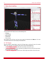
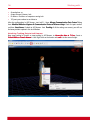
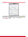
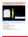
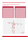
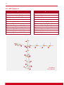
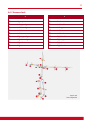
ARTART-Human
Motion Capture User Manual
Version 2.0
Advanced Realtime Tracking GmbH
July 2013
Table of Contents
1
Introduction..................................................................................................................... 1
1.1 What is ART-Human? ...................................................................................................................... 1
1.2 Features .......................................................................................................................................... 1
1.3 New in Version 2.0 ......................................................................................................................... 1
2
Main User Interface ......................................................................................................... 2
2.1
2.2
2.3
2.4
2.5
3
Creating and Calibrating Models..................................................................................... 6
3.1
3.2
3.3
3.4
4
3D Viewer ....................................................................................................................................... 2
Control Window .............................................................................................................................. 3
Models Window .............................................................................................................................. 3
Tools Window ................................................................................................................................. 4
Display Settings .............................................................................................................................. 4
Preparing DTrack ............................................................................................................................ 6
Putting on the MoCap Targets ........................................................................................................ 7
Creating a new Model .................................................................................................................... 8
Calibrating a Model ........................................................................................................................ 9
Output Configuration .................................................................................................... 11
4.1 Retargeting Options ...................................................................................................................... 11
4.2 Output Channels ........................................................................................................................... 12
5
Working with… ............................................................................................................ 15
5.1
5.2
5.3
5.4
5.5
6
ART Hybrid Optical-Inertial Targets ............................................................................................... 15
ART Fingertracking ....................................................................................................................... 15
Siemens PLM Jack ......................................................................................................................... 15
Dassault 3DVIA Studio .................................................................................................................. 19
AutoDesk® MotionBuilder® 2009-2011 ...................................................................................... 19
License Management .................................................................................................... 19
A Bone IDs and Coordinate System Specifications ............................................................ 20
A.1
A.2
A.3
A.4
A.5
ART-Human v2 .............................................................................................................................. 20
ART-Human v2 Fingertracking Assignment ................................................................................... 21
ART-Human v1 .............................................................................................................................. 22
Siemens Jack ................................................................................................................................. 23
Dassault Systèmes Live Motion Standard v1 ................................................................................. 24
Introduction
1
1 Introduction
1.1 What is ART-Human?
ART-Human allows an ART optical tracking systems to be used for Motion Capture. ART-Human can
automatically calibrate the bone lengths of a human body model in a simple calibration procedure to an
accuracy level of 1cm. Using advanced inverse kinematics, the human body pose is reconstructed in realtime and visualized in 3D. The resulting bone positions can be sent in real-time to other applications using
6dj, VRPN or Siemens Jack interfaces or recorded to disk in C3D and BVH formats.
1.2 Features
The most important features of ART-Human are:
•
•
•
•
•
•
•
•
Real-time inverse kinematics solver
Simple calibration procedure
Support of hybrid optical-inertial tracking for better occlusion handling
Full-body and upper-body tracking
Full Fingertracking support
Interfaces to Autodesk MotionBuilder® 2009-2011, Siemens Jack and Dassault Systèmes Live Motion
Standard v1
Real-time output via VRPN, 6dj and Siemens Jack interfaces
Output to C3D and BVH files for animation and motion analysis
1.3 New in Version 2.0
Version 2.0 of ART-Human was rewritten from ground up and includes many new features and bug fixes.
Compared to version 1.x, the most important new features are:
•
•
•
•
•
•
•
•
•
New and more accurate inverse kinematics solver
More detailed spine model
Improved calibration process
Reworked user interface
Full Fingertracking integration
Real-time VRPN output
C3D and BVH file output
Dassault Systèmes Live Motion Standard v1 support
New license model
2
Main User Interface
2 Main User Interface
The user interface of ART-Human consists of the following views:
•
•
•
•
•
3D Viewer
Control Window
Models Window
Tools Window
Display Settings
With exception of the 3D Viewer, each view can be enabled or disabled from the View menu. The views
can be placed freely on the screen by drag and drop operations.
2.1 3D Viewer
When the tracking or target display is active, the 3D Viewer shows a real-time 3D view of the tracked
models, tools and targets. The viewpoint can be moved using the following operations:
•
•
•
To move left/right and up/down, hold the left mouse button and move the mouse
To move forward/backward, use the scroll wheel or hold both the shift key and the left mouse button
while moving the mouse up or down
To rotate the viewing position around the scene, hold the right mouse button and move the mouse
Main User Interface
3
For a full screen view, choose View Full Screen from the menu or press F5 . If the viewing position was
accidentally moved out of the tracking volume, the position can be reset using View Reset View or by
pressing the ESC key. The contents of the 3D Viewer can be changed in the Display Settings view (see
section 2.5).
2.2 Control Window
The control window is used to start and stop the tracking process
and provides some information about the current tracking state.
To start or stop the real-time inverse kinematics tracking and
activate the configured output channel, push Tracking . When no
models are calibrated, a real-time display of the tracking targets as
provided by DTrack (with no inverse kinematics) can be activated by
pressing Display .
Additionally, the following information is provided:
Option
Option
Description
f ps
Frames per second of the output data.
Targets
Number of active tracking targets provided by DTrack.
M odels
Shows the currently tracked models.
2.3 Models Window
The Models Window shows the currently available models and
allows basic operations on the model list. By clicking on the
arrow left of the model name, it is possible to navigate through
the bone hierarchy of each model and view the current target
assignments and bone lengths for each calibrated bone.
To create a new model, press the
button, which will open
the New Human M
Model
odel dialog. You can assign the model a
name, an icon and choose the MoCap target set to use.
Creation of new models is described in more detail in section
3.3. To delete a model, select it and press the button.
The model calibration is started by selecting the model and
clicking on Calibrate . For more details on calibration, see
section 3.4. Manual changes to the target assignment can be reset using the
button.
A calibrated model can be saved to disk using the
button. ART-Human currently supports two formats,
which can be chosen in the Save Model dialog: The human models (*.hm) format contains the whole
hierarchy and calibration data for backup or transfer of calibration to another computer. The segment
descriptions (*.csv) format provides a simple method to export segment lengths for use by other
programs. Note that the segment descriptions do not contain the full hierarchy or calibration information,
4
Main User Interface
and thus cannot be loaded back into ART-Human. An exported human model can be loaded from disk
using the button.
Remark: Normally it is not necessary to explicitly save models except for backup or transferring to
ART--Human automatically saves the models in the Models Window to its
another computer, as ART
internal workspace and loads them on start of the application.
To activate a model for tracking, check the check box left of the model name. Only active models will be
used for inverse kinematics and output.
For target assignment, the double click the Target field of the bone and enter the DTrack target ID.
Special target types such as Flysticks or measurement tools can be specified using the following naming
scheme:
Target IDs
Body Type
01, …, 99
DTrack standard bodies and inertial targets
H01, …, H99
Hand targets used by the finger tracking module
F01, …, F99
Flysticks
M01, …, M99
Measurement tools
Remark: Normally, targets are assigned to bones automatically during calibration. Manual
assignment is only necessary when this does not work for some reason. Manu
Manuaal target assignment
Calibration
can also be done in the Calibrati
on dialog.
2.4 Tools Window
Tools are additional tracking targets which are not used for inverse
kinematics and passed through to the output channel by ART-Human.
Among others, they can be used for prop tracking and interaction
devices.
Clicking on
creates a new tool, while
deletes the selected tool.
By double-clicking on the tool Name, the name can be changed. To
assign a target, double-click the Target field and enter the body id. For
Flysticks, measurement tools, etc. use the same naming scheme as
described in section 2.3.
The buttons
and
save and load the tool name and target assignment to and from a file on disk.
2.5 Display Settings
The contents displayed in the 3D viewer can be customized be
activating and deactivating the various options in the Display
Settings window. The following options are available:
Main User Interface
5
World Display
The following options control the display of items which are always present in the scene:
Option
Option
Description
Grid
Shows a grid on the floor.
Coordinate System
Shows the axes and the origin of the current room coordinate system.
Number of Targets
Shows the number of available and assigned targets.
Human Model Display
The following options control the display of the tracked models:
Option
Option
Description
Spheres
Displays the bones of the tracked model using three-dimensional ellipsoids.
Cones
Displays the bones of the tracked model as cones. In contrast to the Spheres
option, the orientation of bones can be recognized more easily
Lines
Draws straight lines between the joints of the tracked model.
Model Name
Shows the name of the model next to the model’s head. Useful when multiple
models are tracked.
Segment IDs
Draws the bone IDs next to each bone. Useful for debugging the output.
Joints
Draws the joint locations as spheres.
Coordinate Systems
Draws a coordinate system at the origin of each bone.
Retargeted Model
If activated, the retargeted model is shown, as sent to the output channel.
Otherwise, the internal representation is shown.
Target Display
The following options control the display of DTrack tracking targets, i.e. of ART-Human’s inputs:
Option
Option
Description
Coordinate Systems
Draws a coordinate system at the origin of each target.
Target IDs
Draws the target ID next to each target’s location. Useful for checking the target
assignment.
6
Creating and Calibrating Models
Tool Display
The following options control the display of tools:
Option
Option
Description
Name
Draws the name of the tool next to its location.
IDs
Draws the numeric ID of the target next to its location. Whether the ID or the
name is output depends on the selected output channel (see section 4.2).
Coordinate System
Draws a coordinate system at the origin of each tracked tool.
Sphere
Draws a sphere at the origin of each tracked tool.
3 Creating and Calibrating Models
Before a model can be tracked, a number of steps have to be performed, which consist of:
•
•
•
•
Setting up the DTrack system
Putting on the MoCap Suit
Creating a new model
Calibrating the model
3.1 Preparing DTrack
For setting up the camera system and to perform an initial room calibration, please follow the instructions
given in the DTrack user manual.
Calibrating the Tracking Targets
To track the targets of the MoCap suit with the camera system, a body
body calibration of all tracking targets
must be performed in the DTrack software once. The simplest solution is to use the Target Library method
which allows the simultaneous calibration of all MoCap targets, even when already worn on the body.
Please refer to the DTrack2 user manual for details.
In cases where body calibration using the target library is not possible (e.g. when using an older target set
or an older DTrack version), each target must be calibrated individually using the Custom Calibration
method. We recommend calibrating using the due to room coordinate system setting.
Remark: There is no need to calibrate targets in any particular order or to assign particular body
IDs. In most cases, the correct assignment is automatically computed during calibration.
Configuring DTrack Output
Finally, please configure DTrack to send the tracking data to the computer running ART-Human. The
simplest method is to run the DTrack Frontend on the same computer as ART-Human, open
Settings Output , activate an output C hannel and set the destination to this computer .
Please also make sure that at least the fields ts and 6d are enabled. If you want to use additional target
types such as Flysticks, measurement tools or inertial bodies, please enable the respective output fields as
well.
Creating and Calibrating Models
7
Remark: When using inertial targets, make sure to have the 6di field enabled. Otherwise, inertial
ART--Human will not behave correctly in occlusion situations.
targets may seem to track, but ART
Configuring ART-Human Input
After configuring the output channel in DTrack, go back to ARTHuman and open Main Input Configu
Configuration
ration from the menu.
Make sure that the DTrack UDP port number matches the one of
the DTrack output channel and set the ground plane to
correspond to the room calibration setting of DTrack.
3.2 Putting on the MoCap Targets
After DTrack is configured appropriately, please put on the tracking targets. Each target contains a small
symbol indicating where on the body it should be worn.
When putting on the target set, there are several important points to consider:
8
Creating and Calibrating Models
•
The chest and hip targets can be worn either in front or back of the body
•
The hip target is best worn in the middle of waist, not on the left or the right side
•
The foot targets should be near the tip instead of near the ankle
Finally, walk around in the tracking volume and check if all the targets can be tracked well.
3.3 Creating a new Model
A new model is created by pressing the
button in the Models Window , which opens the New Human
Model dialog. Please enter a descriptive name and optionally choose an icon.
Creating and Calibrating Models
9
Under Type of MoCap set , please choose the target set you want to use. Currently, the following target
sets are supported.
•
•
Full body (17 targets): A full body target set, consisting of the following targets: hip, chest, head,
shoulders (2x), upper arms (2x), lower arms (2x), hands (2x), upper legs (2x), lower legs (2x) and feet
(2x).
Upper body (7 targets): A simplified target set for tracking arms and head only. It consists of the
following targets: head, upper arms (2x), lower arms (2x) and hands (2x).
Using this target set, tracking will start with the upper thoracic spine and bones below will not be part
of the output stream. Also note that this target set does not allow tracking of the correct torso
orientation and thus, the torso will always be standing upright.
If you want to use ART-Human together with Fingertracking, please also tick the left hand and/or right
hand checkboxes. After clicking OK, the model will be created and can be calibrated.
3.4 Calibrating a Model
To calibrate a new or existing model, first click on the model in the Models Window and then click
Calibrate . Now, the Human Model Calibration dialog should open.
Target Assignment
If you want to use the automatic target assignment, please check the box Assign Targets
automatically . In this case, remove any tracking targets that do not belong to the model from the tracking
volume, so that only targets on the person are tracked by DTrack during calibration. Any other targets in
the volume may cause the automatic assignment to fail.
10
Creating and Calibrating Models
If you want to keep the current target assignment or override the assignment manually, disable the check
box and enter target IDs manually. For targets other than standard bodies, follow the target naming
scheme given in section 2.3.
Starting the Calibration in T Posture
To start the calibration, press Start . After a five seconds count-down, data recording will start. At the
beginning of the calibration, the person must be standing in T posture, i.e. upright with arms pointing
away from the body, as shown in the picture below. If the T posture is not set appropriately, there will be
displacements between the calculated human model and the real motion. It is particularly important that
•
•
•
•
the feet are parallel and standing firmly on the ground
the hands are flat and oriented parallel to the ground
the neck is stretched upwards
the head is looking forward (and not to a screen standing on the side)
Output Configuration
11
Joint Calibration Movement
After the data recording has started while standing in T posture, move all limbs until all progress bars
reach 100% in order to calibrate the bone lengths and target position. The calibration will automatically
finish when enough motion is recorded.
Remark: Please cconsider
onsider that most joints can be rotated in two or three axes and move the limbs
accordingly. Rotating all possible axes may greatly improve calibration quality!
After the calibration has finished, push Tracking and move inside the tracking volume to test the motions
of the calibrated model. If you are not satisfied with the results, try to calibrate again, putting extra
emphasis on the motions of the body parts that did not look correct.
4 Output Configuration
In order to define the output of ART-Human, open
Main Output Configuration from the main menu. In
the Output Configuration dialog, two separate aspects
need to be configured:
•
•
the retargeting of the model, defining the world
units, the available bones and their orientations
the actual output channel used to transmit data to
an application
In general, ART-Human allows all available options to be
combined freely; however, specific applications may
require specific settings. More information about the
settings required for certain applications are given in
section 5.
4.1 Retargeting Options
ART-Human provides a number of pre-defined retargeting settings which specify the following aspects of
the model data sent to the application:
•
•
•
•
number of bones
orientation of the bones
numeric IDs of the bones
distal or proximal bone coordinates
By clicking on the Details button, a preview of each retargeted model with target IDs and bone
orientations can be seen. The following retargeting settings are available:
ART-Human v2 (Default)
This default setting contains the new spine model with four spine segments. In T-pose, all bones are
oriented such that X points left, Y points backwards and Z points up. The ART-Human v2 setting uses
proximal bone coordinate systems, i.e. the origins are located at the bone end closer to the pelvis. Please
refer to appendix A.1for details about the coordinate systems and bone IDs.
12
Output Configuration
Unless required by some other application, we recommend using this setting as it most accurately
describes the result of ART-Human’s inverse kinematics.
The ART-Human v2 configuration also supports the ART Fingertracking. When Fingertracking is activated,
the orientations and positions of the finger bones are sent to the configured output channel along the
ART-Human bones. Please refer to appendix A.2 for bone IDs and to section 5.2 for general Fingertracking
settings.
ART-Human v1
The ART-Human v1 retargeting setting is provided for compatibility with older versions of ART-Human. The
setting uses a distal bone representation, i.e. the origin of the bone coordinate systems is at the end of the
bone that is further away from the pelvis in T posture. Compared to v2, the spine contains fewer segments
and the orientation of the right arm is changed such that the x axis points outwards. Please refer to
appendix A.1 for details about the coordinate systems and bone IDs.
Siemens Jack
This retargeting setting is suitable for use with the Siemens PLM Jack software. It uses two spine and one
neck segment. The y axis of each bone coordinate system points along the bone in an outward direction.
The z axis points towards the front, with the exception of the feet where it points upwards. Please refer to
appendix A.4 for details about the coordinate systems and bone IDs.
Dassault Systèmes Live Motion Standard v1
This retargeting setting is suitable for use with Dassault software such as 3DVIA Studio. It uses the same
spine model as ART-Human v2 but adds additional coordinates systems for the toes (which are not tracked
by ART-Human). The y axis of each bone coordinate system points along the bone in an outward direction.
The z axis points towards the front, with the exception of the feet where it points upwards. Please refer to
appendix A.5 for details about the coordinate systems and bone IDs.
General Retargeting Settings
ART-Human provides a number of general retargeting settings which may be applied to all models:
Option
Option
Description
unit
Determines the unit in which the bone positions are given. Available choices are
meters (m), centimeters (cm) and millimeters (mm).
ground plane
ART-Human can apply an extra rotation to the output data which is configured
here. Output coordinate systems are always right-handed.
4.2 Output Channels
The output settings define the output channel that is used to send the retargeted bone coordinates to an
application. Currently, the following choices are available:
6dj/UDP
This setting makes ART-Human send UDP packages to a client application. It extends the standard UDP
format used by DTrack with a 6dj line that contains the 6DoF pose of each bone in the retargeted models.
Output Configuration
13
Please refer to the technical appendix of the DTrack User Manual for a general introduction to the format.
The destination IP address and UDP port of the UDP packets can be specified in the dialog.
An example frame looks like this:
fr 34514
ts 64425.076492
6d 15 [0 1.000][522.1646 -141.5154 1347.3978 0.3947 0.2996 89.6321][0.006420 0.999956 0.006855
-0.999966 0.006384 0.005273 0.005229 -0.006889 0.999963][1 1.000]…
6dj 3 1 [0 20][0 1.000][562.7647 -128.7422 781.4459 -0.0000 0.0000 87.8071][0.038265 0.999268
0.000000 -0.999268 0.038265 0.000000 0.000000 0.000000 1.000000][1 1.000][564.9398 -128.8686
966.4164 1.1212 2.2889 88.7907][0.021088 0.999602 0.018721 -0.998980 0.020320 0.040335
0.039939 -0.019552 0.999011][2 1.000][522.1646 -141.5154 1347.3978 0.3947 0.2996
89.6321][0.006420 0.999956 0.006855 -0.999966 0.006384 0.005273 0.005229 -0.006889
0.999963][3 1.000][654.3460 -144.7520 1504.9670 -1.5249 1.7823 90.0123][-0.000215 0.999646 0.026605 -0.999516 0.000613 0.031097 0.031102…
Where the meaning of each line is:
Line tag
Description
fr
DTrack frame counter
ts
Time stamp in seconds
6d
Number of tracked tools, for each tool followed by
[id qu][sx sy sz η θ φ][b0 … b8]
•
•
•
•
Id number (id, starting with 0) of the tool
quality value qu (not used)
Position sx sy sz and euler angles η θ φ
Rotation matrix b0 … b8 of the tool’s orientation
Please refer to the DTrack User Manual for an exact definition of euler angles and rotation
matrices.
6dj
Number of calibrated models, number of output models. For each output model, the
following element appears:
[id num]
•
•
Id number (id, starting with 0) of the model
Number num of retargeted bones.
For each retargeted bone, the [id num] element is followed by num elements of the form
[id qu][sx sy sz η θ φ][b0 … b8]
These have the same definition as for the 6d field above and represent the retargeted bone
pose relative to the world coordinate system.
14
Output Configuration
Siemens Jack
In order to communicate with Siemens PLM Jack, use this output format, which opens a TCP network
connection to Jack. The destination IP address and TCP port number of Jack can be specified. For Jack
configuration, see section 5.3.
VRPN
When this output setting is activated, ART-Human opens a VRPN server to transmit retargeted bone poses.
The local port number of the server can be specified. For each retargeted model, a tracker is created having
the same name as the model. Each bone is represented by a sensor using the IDs specified in the
retargeting settings. We recommend also setting the unit settings to m to conform to the VRPN
conventions.
For each defined tool, a dedicated tracker is created having the same name as the tool. A single sensor
with id 0 transmits tool position and orientation on each tracker.
C3D file
For offline storage of tracking data in C3D format, please use the C3D file output setting. Each time the
tracking is started, a new file is created in the specified directory. The file name will consist of the current
date and time. In C3D, each bone’s position and orientation is described using three “virtual markers”
which are distributed as follows:
Marker ID
Location
0
At origin of bone coordinate system
1
20mm along the y axis of the bone
2
20mm along the z axis of the bone
Each marker is named according to the following naming scheme:
h<modelid>b<boneid>m<markerid>
Where modelid is the number of the model, boneid is the id of the bone as specified by the
retargeting setting and markerid is the id of the virtual marker as specified by the table above.
For tools, the naming is
tool<toolid>m<markerid>
Where toolid is the number of the tool and markerid is the id of the virtual marker as specified by
the table above.
BVH file
For offline storage of tracking data in BVH format, please use the BVH file output setting. Each time the
tracking is started, a new file is created in the specified directory. The file name will consist of the current
date and time. BVH files contain the full bone hierarchy of the retargeted models. The pose of the bones is
then described using relative angles. The generated file contains all tracked models and tools using the
names specified in the Model/Tool Windows.
Working with…
15
If the exact position of extremities matters (and not just the joint angles), we recommend to use the ARTART Human v2 retargeting setting.
5 Working with…
The following section explains how to interface ART-Human with special ART tracking targets and with 3rd
party software.
5.1 ART Hybrid Optical-Inertial Targets
The ART hybrid optical-inertial motion capture targets contain wireless inertial sensors that allow
continuous motion capture even when a large part of the targets can no longer be seen by the optical
tracking cameras.
To setup inertial targets in DTrack, follow the instructions in the DTrack2 user manual. Do make sure that
the 6di output format is enabled in the DTrack output settings. When 6di is not enabled, the inertial
targets may seem to work, but will not produce correct results in occlusion situations.
To use inertial target in ART-Human, simply treat them the same way as standard targets. ART-Human will
automatically recognize the inertial functionality when the 6di output is active.
5.2 ART Fingertracking
As of version 2, ART-Human fully integrates the ART Fingertracking system, enabling live preview of the
finger poses in the 3D viewer. Additionally, finger bone data can be sent with the normal output channels
of ART-Human.
To setup the Fingertracking and calibrate the hands in DTrack, please follow the instructions provided
by the DTrack2 user manual. Also make sure that the gl and glcal outputs are enabled in the DTrack
output settings.
After calibrating the hands in DTrack, switch to ART-Human and create a new model. In the New Model
dialog, check the right hand and/or left hand boxes, depending on which hands you want to use. The
model can now be calibrated normally. If you don’t want to use the automatic target assignment, please
enter H01 , H02 , etc. as the target IDs for the hands.
In the ART-Human Output Settings dialog, choose the ARTART - Human v2 retargeting, as this is the only
setting that supports Fingertracking.
5.3 Siemens PLM Jack
Please also refer to the document TrackingJackFigures.
TrackingJackFigures.pdf
pdf provided by Siemens PLM.
ART-Human Settings
First, follow the instructions given in section 3 to calibrate the human model until the tracking can work
normally. Then configure the output settings as follows:
•
•
Retargeting: Siemens Jack
Unit: cm
16
•
•
•
•
Working with…
Ground plane: zx
Output channel: Siemens Jack
IP address: IP address of computer running Jack
TCP port: port number to send data to
After the configuration in ART-Human, start Jack7.1. Open Mocap Communication Port Control dialog
from Modules Motion Capture Comm
Communication
unication Protocol Server Setup . Check the port number
and then Start Server . Go back to ART-Human. Start Tracking . If all the settings are correct, you will see
the bone positions update in the Jack Window.
Attaching Tracking Data to Jack Humans
Now stop tracking in Dtrack2 or stop tracking in ART-Human, to freeze the data at T Pose. Create a
Default Male or Female Human in Jack. Right click on the human and scale it to the correct height.
Working with…
17
Open Mocap Tracking dialog from Modules Motion Capture Communication Protocol Tracking
Setup . Press Add to open Tracking Setup dialog. Pick up the Human Figure by pressing and click the
mouse on the Human. Press Add Pair . Press Constrain in the Mocap Track
Tracking
ing dialog and now the
human is constrained to the joints data.
18
Working with…
Tool Tracking
In the Tool Window of ART-Human, create tools to send to Jack. Set the target id and the name of the tool,
check the checkbox in front. Then in the tracking mode, the tool target data will be send to Jack as the
name “Tools_b_<toolname>”.
Starting and Stopping Tracking
The work routine to communicate with Jack should be:
1.
2.
3.
4.
Start Server in Mocap Communication Port Control
Start Tracking in ART-Human
Stop Tracking in ART-Human
Stop Server in Mocap Communication Port Control
Otherwise, the communication might have a problem and cause a crash of Jack.
License Management
19
5.4 Dassault 3DVIA Studio
First, follow the instructions given in section 3 to calibrate the human model until the tracking can work
normally. Then configure the output settings as follows:
•
•
•
•
Retargeting: Dassault Systèmes Live Motion Standard v1
Unit: m
Ground plane: xy
Output channel: VRPN
3DVIA also requires the first tracked model to be named “User0”, the second “User1”, etc.
To connect to ART-Human from 3DVIA Studio, please follow the instructions in the 3DVIA documentation.
5.5 AutoDesk® MotionBuilder® 2009-2011
Please refer to the document MotionCapturingwithDtrack_v1.1.
MotionCapturingwithDtrack_v1.1.pdf
pdf .
6 License Management
ART-Human is using USB dongles for copy protection and license storage. The USB dongle must be present
on a USB port of the computer while ART-Human is running.
The USB dongles require special drivers which normally are installed by the ART-Human setup program. In
case of problems, the latest version of the drivers (CBUSetup) can be downloaded from the following
website:
https://www.marx.com/de/support/downloads
For licensing questions or to obtain additional licenses, please contact your ART sales representative.
20
A Bone IDs and Coordinate System Specifications
A.1 ART-Human v2
Bone ID
Bone Assignment
Bone ID
Bone Assignment
0
Pelvis
11
Right shoulder
1
Lower lumbar spine
12
Right upper arm (humerus)
2
Upper lumbar spine
13
Right lower arm (radius/ula)
3
Lower thoracic spine
14
Right hand
4
Upper thoracic spine
15
Left upper leg (femur)
5
Neck
16
Left lower leg (fibula/tibia)
6
Head
17
Left foot
7
Left shoulder
18
Right upper leg (femur)
8
Left upper arm (humerus)
19
Right lower leg (fibula/tibia)
9
Left lower arm (radius/ula)
20
Right foot
10
Left hand
21
A.2 ART-Human v2 Fingertracking Assignment
If Fingertracking is activated, additional bones will be used to represent the state of all finger segments.
For the meaning of the segments, see the DTrack2 user manual. Note that the coordinate system
orientation of the finger segments in ART-Human is the same as that of the corresponding hand.
Bone IDs
Fingertracking Bone Assignments
2121 -24
Left thumb: root, middle, outer, tip
2525 -28
Left index finger: root, middle, outer, tip
2929 -32
Left middle finger: root, middle, outer, tip
3333 -36
Left ring finger: root, middle, outer, tip
3737 -40
Left pinky: root, middle, outer, tip
4141-44
Right thumb: root, middle, outer, tip
4545 -48
Right index finger: root, middle, outer, tip
4949 -52
Right middle finger: root, middle, outer, tip
5353 -56
Right ring finger: root, middle, outer, tip
5757 -60
Right pinky: root, middle, outer, tip
22
A.3 ART-Human v1
Bone ID
Bone Assignment
Bone ID
Bone Assignment
0
Pelvis (“hip”)
10
Left hand
1
Lower spine (“chest”)
11
Right hand
2
Upper spine (“neck”)
12
Left hip
3
Head
13
Right hip
4
Left shoulder
14
Left upper leg (“knee”)
5
Right shoulder
15
Right upper leg (“knee”)
6
Left upper arm (“elbow”)
16
Left lower leg (“ankle”)
7
Right upper arm (“elbow”)
17
Right lower leg (“ankle”)
8
Left lower arm (“wrist”)
18
Left foot
9
Right lower arm (“wrist”)
19
Right foot
23
A.4 Siemens Jack
Bone ID
Bone Assignment
Bone ID
Bone Assignment
0
Pelvis/lower spine
10
Neck
1
Upper spine
11
Head
2
Left upper leg
12
Left shoulder
3
Left lower leg
13
Left upper arm
4
Left foot
14
Left lower arm
5
Left toes
15
Left hand
6
Right upper leg
16
Right shoulder
7
Right lower leg
17
Right upper arm
8
Right foot
18
Right lower arm
9
Right toes
19
Right hand
24
A.5 Dassault Systèmes Live Motion Standard v1
Bone ID
Bone Assignment
Bone ID
Bone Assignment
0
Pelvis
12
Spine4
1
Left upper leg
13
Left Shoulder
2
Left lower leg
14
Left upper arm
3
Left foot
15
Left lower arm
4
Left toe
16
Left Hand
5
Right upper leg
17
Right Shoulder
6
Right lower leg
18
Right upper arm
7
Right foot
19
Right lower arm
8
Right toe
20
Right Hand
9
Spine1
21
Neck
10
Spine2
22
Head
11
Spine3