1
4.2
Expansion Module MAC00-B1/B2/B4
4.2.10
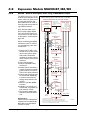
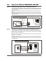
Connecting a PNP signal source to the Multifunction I/O
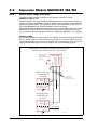
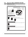
The drawing below shows how to connect a PNP source to the MAC00-B1, B2 or B4
multifunction I/Os. The diagram shows the A channel. The B channel must be connected
in the same manner.
Ensure that the A- and B- terminals are unconnected in order to maintain proper function.
Warning: Voltages higher than 5V must under no circumstance be connected directly to
the input since this will damage the input permanently. Use a proper resistor as indicated
in the table below.
PNP (source) output connected to the A and B input
Power
Supply
5-32VDC
+
PNP
Output
switch
Optional
resistor
See table
Dip-Switch setting:
NPN
A+
PNP
INPUT
SETUP + NPN
B PNP
B+
A+
Warning:
Never connect voltages
higher than 5V directly to
the A or B terminals since
this can damage the inputs.
OCM
If used, the B+ terminal must be connected in the same manner as the A+ terminal.
The A- and B- terminals must be left unconnected.
TT0941GB
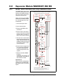
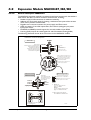
Connecting a balanced/push-pull signal to the Multifunction I/O
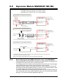
The drawing below shows how to connect a balanced or push-pull signal source to the
MAC00-B1, B2 or B4 multifunction I/Os. Use twisted-pair cable for the balanced signals
in order to ensure noise immunity.
Note: If inputs are used in pulse-direction format input A (A+/A-) is pulse input and input
B (B+/B-) is direction input.
Warning: Voltages higher than 5V must under no circumstance be connected directly to
the input since this will damage the input permanently. Use a proper resistor as indicated
in the table below.
Balanced or push-pull output connected to the A and B input
MAC motor with MAC00-B1, B2 or B4 expansion module
BOCM
Signal GND
RS422 outputs (balanced)
Twisted pair cable is recommended
OFF
OFF
OFF
OFF
A
B+
B
1 2 3 4
A-
From internal
Control circuitry
NPN
A+
PNP
INPUT
SETUP + NPN
B PNP
ON
A+
A
P u ls /d ir
Dip-Switch setting:
External pulse source
F o rm a t
Q u a d ra tu re
4.2.11
OFF
ON
OFF
ON
Dipswitch 5+6 only at MAC00-B4.
Please consult the B4 chapter.
BA-
Ground
1 2 3 4
Signal source (PLC)
MAC motor with MAC00-B1, B2 or B4 expansion module
Resistor size
0 Ohm (none)
390 Ohm
1 kOhm
1.2 kOhm
1.8 kOhm
2.7 kOhm
3.3 kOhm
ON
Supply:
5VDC
8VDC
12VDC
15VDC
18VDC
24VDC
30VDC
B
Dipswitch 5+6 only at MAC00-B4.
Please consult the B4 chapter.
Warning:
Never connect voltages
higher than 5V directly to
the A or B terminals since
this can damage the inputs.
TT0943GB
JVL Industri Elektronik A/S - User Manual - Integrated Servo Motors MAC050 - 3000
125