1
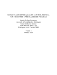
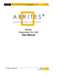
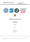
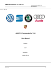
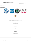
Calar Alto AutoGuider User Manual.
José Ignacio Vico ([email protected])
Jesús Aceituno ([email protected])
October 18, 2012
1
Contents
1 Outline.
3
2 Connection and start.
3
3 What dialogues can
3.1 Selector. . . . . .
3.2 Main. . . . . . .
3.3 Full frame. . . .
3.4 Console. . . . . .
3.5 Stages. . . . . . .
3.6 Parameters. . . .
3.7 Telescope. . . . .
3.8 Plot. . . . . . . .
you find?.
. . . . . . .
. . . . . . .
. . . . . . .
. . . . . . .
. . . . . . .
. . . . . . .
. . . . . . .
. . . . . . .
.
.
.
.
.
.
.
.
.
.
.
.
.
.
.
.
.
.
.
.
.
.
.
.
.
.
.
.
.
.
.
.
.
.
.
.
.
.
.
.
.
.
.
.
.
.
.
.
.
.
.
.
.
.
.
.
.
.
.
.
.
.
.
.
.
.
.
.
.
.
.
.
.
.
.
.
.
.
.
.
.
.
.
.
.
.
.
.
.
.
.
.
.
.
.
.
.
.
.
.
.
.
.
.
.
.
.
.
.
.
.
.
.
.
.
.
.
.
.
.
.
.
.
.
.
.
.
.
.
.
.
.
.
.
.
.
.
.
.
.
.
.
.
.
.
.
.
.
.
.
.
.
.
.
.
.
.
.
.
.
4
4
4
5
7
8
9
10
11
4 Using the mouse.
12
4.1 Left button. . . . . . . . . . . . . . . . . . . . . . . . . . . . . . . 12
4.2 Right button. . . . . . . . . . . . . . . . . . . . . . . . . . . . . . 12
4.3 Middle button. . . . . . . . . . . . . . . . . . . . . . . . . . . . . 12
5 Menus.
5.1 “File” menu. . . . .
5.2 “View” menu. . . . .
5.3 “Marks” menu. . . .
5.4 “Acquisition” menu.
.
.
.
.
.
.
.
.
.
.
.
.
.
.
.
.
.
.
.
.
.
.
.
.
.
.
.
.
.
.
.
.
.
.
.
.
.
.
.
.
.
.
.
.
.
.
.
.
.
.
.
.
.
.
.
.
.
.
.
.
.
.
.
.
.
.
.
.
.
.
.
.
.
.
.
.
.
.
.
.
.
.
.
.
.
.
.
.
.
.
.
.
.
.
.
.
.
.
.
.
12
12
13
14
14
6 Operation.
6.1 Initialization. . . .
6.2 Focus. . . . . . . .
6.3 Normal operation.
6.4 Finalize. . . . . . .
6.5 Marks. . . . . . . .
.
.
.
.
.
.
.
.
.
.
.
.
.
.
.
.
.
.
.
.
.
.
.
.
.
.
.
.
.
.
.
.
.
.
.
.
.
.
.
.
.
.
.
.
.
.
.
.
.
.
.
.
.
.
.
.
.
.
.
.
.
.
.
.
.
.
.
.
.
.
.
.
.
.
.
.
.
.
.
.
.
.
.
.
.
.
.
.
.
.
.
.
.
.
.
.
.
.
.
.
.
.
.
.
.
.
.
.
.
.
.
.
.
.
.
.
.
.
.
.
.
.
.
.
.
14
14
14
15
15
15
.
.
.
.
.
7 Remote Operation.
16
7.1 Protocol. . . . . . . . . . . . . . . . . . . . . . . . . . . . . . . . 16
8 Troubleshooting.
17
8.1 Frozen image. . . . . . . . . . . . . . . . . . . . . . . . . . . . . . 17
2
1
Outline.
The system is based on PC. It has one or two cameras (depending on telescope
and instrument) for imaging. The optical control is done through electronic
old system, although a new compatible electronic have been developed. The
telescope control is done via serial port using the former system and is intended
precisely to the connection of a system guided.
Camera
AG Ring
Camera
TELESCOPE
USB
NPort
RS422
tecs
RS232
NPort
Electronics
PC
LAN
Figure 1: Outline of the system.
Figure 1 is the outline of the system. In it is possible to identify the components mentioned above and how are they connected. The communication
between system modules is Ethernet network, using a serial port server (NPort)
for serial communication.
2
Connection and start.
The operation of the Auto Guider is done through a remote desktop to the
control PC of the system.
All the different systems have the same user and password to login:
User: ag
Password: aGui2er
Each telescope and instrument have a different PC to connect:
1.23m Telescope: ag12.caha.es
2.2m Telescope CAFOS and CAFE : ag22.caha.es
2.2m Telescope BUSCA: agx.caha.es
3.5m Telescope: ag35.caha.es
3
The PC for BUSCA in 2.2 telescope is the reserve for any breakdown PC in
other instrument or telescope.
Once you have started the remote desktop and logged in you can find the
icon to run the software: AutoGuider.
3
3.1
What dialogues can you find?.
Selector.
Figure 2: Instrument selection dialogue.
The first dialogue shown when starting the software is an instrument selector,
which allows you to select which of the configuration files stored on the PC use.
The default selection will be the one used in the last run of the software.
3.2
Main.
The main dialogue is the first you can see once the software set-up is selected;
this dialogue is the only one that is essential for the operation of the AutoGuider;
other dialogues can be opened from main dialogue and they have more specifics
functions or general information functions.
Figure 3: Main dialogue.
In this dialogue you can find: two buttons: “Start” and “Stop”, an image
display with associated cut values, a message line, a process bar and two text
that show the connection state with telescope and electronics.
“Start” Button: Start guiding. By clicking this button the automatic guiding
Starts. Initially the button colour is soft green. While the initialization
of the guiding the button turns yellow. the system takes an image, analyses it looking for valid stars for guiding and, if it finds some, begins the
4
automatic guiding in the selected star. In case there is no valid star for
guiding the system will move the camera field and repeat the image acquisition until a valid star is founded, this movement will be done only
if it is possible (is in Guide-Field mode and is allowed to move) and is
checked “Guidefield auto search” in “Stages” dialogue (described in section 3.5). If it cannot find any star above the whole field the system will
open the “Full frame” dialogue (described in section 3.3) and will ask you
for a manual selection of the guiding star (the manual selection can ever
be done in the “Full frame” dialogue). During guiding the “Start” button
turns light green. If the reference guiding star is lost the button turns blue
and no corrections are send to telescope until the start is founded again
and guiding continues in normal way.
“Stop” Button: Stops all the actions the system is doing. When this button
is clicked the guiding or the imaging acquiring is stopped. The system
goes in a “stand by” status waiting for any new command.
Image display: Depending on the state of the software and other opened dialogues, the display will show different images. In the start of the execution
it shows the full reduced last acquisition. If the “Full frame” dialogue is
opened the display shows a zoom of the environment of the pointer over
the full frame display in the “Full frame” dialogue (described in section
3.3). If the software is in guiding state the display shows the environment
of the guiding position. A red crux marks the reference position of the
guiding star, a green crux marks the current position of the mass centre
of the guiding star.
Messages line: Under the image display we can find a text line that shows
interactive information: absolute position of the cursor when it is in the
image display or the horizontal and vertical width of guiding star when
guiding is active.
Process bar: On the process bar it is shown the time evolution of the acquisition exposure.
Communication Monitors: there are two different monitors: one monitor for
the communication with telescope ans another one for the communication
with optics control electronics. Monitors consists in a text line with the
state of the communication. The text indicates if the communication
is correct (“OK”), if there was a prompt error in communication (“No
answer”) or if it has been impossible to establish the connection from the
beginning (“Not conect”). These monitors can be helpful in the initial
diagnosis of faults.
3.3
Full frame.
“Full frame“ dialogue shows the last acquired full frame by the active camera.
In this dialogue we can identify a display box where images are shown and
a zone of buttons and text to interact with the system.
Image display: Shows the last image acquired by the active camera. This
display is actualized automatically on each acquiring of the active camera.
5
Figure 4: Full frame dialogue.
When the cursor moves inside the display the image display in the main
dialogue actualizes with the zoom of the zone around the position of the
cursor in the image (see section 3.2).
Cut values set: At the right of the image display you can find two text boxes
where can be set the upper and lower cut values for the shown image.
Position and value text: In this text are shown the instant position of the
cursor over the image and the image value in this position.
“Show marks” selector: when this selector is marked the follow marks, Slit
position mark and user marks are superimposed on the image. When it
is not marked none mark will be shown in the image.
“Threshold” set: The threshold value can be modified for the automatically
selection of the guiding star. This is done by changing the value in the
edit box and pressing the button “Apply Threshold”.
“Take image” button: By clicking “Take image” button the system will acquire an image with the active camera and will show it in the image
display, after this the system remains in “Stand by” state waiting for new
commands.
6
“Take continuous” button: By clicking “Take continuous” button the system will acquire images in a continuous way, showing each image in the
image display once is acquired. The continuous acquisition of images stops
when the guiding begins or when “Stop” button is clicked in this dialogue
or the main dialogue (section 3.2).
“Move telescope” button: “Move telescope” button let you send controlled
movements of the telescope. Once is clicked the system ask for setting the
origin point of the movement with a double click on the right button of
the mouse, after this ask for the setting of the destiny point with the same
button of the mouse. The system will move the telescope in the way that
the part of the image in the origin point will appear in the point set as
origin point.
“Centre on Slit” button: “Centre on Slit” button moves the telescope to
get the part of the image set as origin with a double click on the right
button of the mouse in the position set as slit position in the setting file.
The setting of the slit position can be done with “Set Slit Pos” button.
“Set Slit Pos” button: The slit position can be changed in the setting file
with the “Set Slit Pos” button. When the “Set Slit Pos” button is clicked
the system ask for the position of the slit in the image with a right button double click of the mouse. Once the position is selected the system
overwrites the setting file and generates a new marks file with the new
position of the slit. (see section 5.3).
“Stop” button: The “Stop“ button of this dialogue has the same function
of the “Stop” button in the main dialogue. It stops any activity in the
software, letting the system in a stand by state.
“Exposure time” set: With this text box the exposition time for the images
taken with the current camera can be set. When this value is modified
the value of the equivalent text box in the “Parameters” changes to the
same value (see section 3.6).
Information box: In this text box will appear information on what is the
system doing, it will show instructions to interact with the system.
“Dismiss” Button: This button closes “Full frame” dialogue; none of the
activities or states in the system will be affected.
3.4
Console.
In this dialogue are shown the system information messages for the user. Messages have an importance hierarchical criteria. A selection of the highest level
to show can be done for the text console and for the log file.
Different hierarchy levels are:
0.- Free.
1.- Free.
2.- Main errors.
3.- Blocks / basic information.
7
Figure 5: Console dialogue.
4.5.6.7.8.9.-
3.5
Minor errors.
Steps inside blocks.
Secondary messages.
Working states (debug mode).
Received messages (debug mode).
Sent messages (debug mode).
Stages.
The ”Stages“ dialogue lets take the control of the electronic of the system.
Figure 6: Stages dialogue.
Elements in this dialogue are disposed in function groups for a better identification:
“Motors” group: With two control bars to set the position of focus and guide
field:
“Focus” bar: Bar with values from 100 to -100. With it the current
camera focus position can be set. Each camera has its own focus
position and is conserved when mode is changed. When software is
closed the current position of focus in each mode are saved in a file
in order to set the same focus position in the next execution of the
software.
8
“Guide field” bar: Bar with values from 100 to -100. With it is set the
position of the guiding field in “Off Axis” camera.
“Camera” group: With this group the operation mode of the system is set:
“Acquisition” mode: In this mode the field that covers the camera is
the same field that covers the instrument. (Warning, the AutoGuider
system is vignetting).
“Slit-View” mode: The camera shows the image of the slit of the installed instrument.
Modo “Guide-Field”: The camera shows a field ”Off Axis” for guiding
out of the instrument field.
“Filters(On Axis)” group: With this group a filter can be selected.
Not all the systems have all the possibilities of the electronics, so, the specific
setting for each instrument defines what controls are available and disables in
the dialogue the controls that are not available.
3.6
Parameters.
In this dialogue are set some parameters for the proper working of the system.
It is possible to save it to the setting file to make changes permanent.
Figure 7: Parameters dialogue.
“OK” button: Closes the window without any other effect in the system.
“Save” button: Save the current parameters in the current setting file chosen
at the initial selector (see section 3.1).
“Aggressiveness Factor” setting: In this text box the value of the aggressiveness factor can be set. The aggressiveness factor is the factor in which
is decreased the calculated guiding correction movement of the telescope,
is expressed as a percentage of the total. The goal of the aggressiveness
factor is to avoid the overshoot in corrections. In case of overshoot as
oscillations with increasing amplitude this factor must be decreased.
9
“Exposure time”: In this text box the exposure time for the images taken by
the current camera can be set. By the value in this text box the value
in the equivalent text box in “Full frame” dialogue is modified too (see
section 3.3).
“Centering position” set: In those text boxes can be set the coordinates of
the centre of the slit. The coordinates of the centre of the slit is the point
of the image in the “Full frame” where the selected start is sent when is
clicked the button “Centre on Slit” in this dialogue. The values can be
set writing them directly in the text boxes or through the action of the
“Set Slit Pos” button in the “Full frame” dialogue (see section 3.3).
“Mark size” set: In this text box can be set the size of the marks placed
by users over the image of the “Full frame” dialogue. The explanations
about the marks system in the software can be found in section 6.5 of this
manual.
Statistical “Window” size: In this text box can be set the size of the window
used for make the statistical computing.
3.7
Telescope.
This dialogue allows to obtain information about the telescope and gives a way
to interact with it.
Figure 8: Telescope dialogue.
It is divided into groups for better organization of its elements.
“OK” button: Close the dialogue without any other effect on the system.
10
“Move Telescope” group: Moves the telescope the indicated amount of arcseconds in the edit box (is possible to introduce decimal numbers) in the
direction given by each of the four directional buttons.
“Telescope Data” group: Displays the information obtained in the last communication. This information can be refresh by clicking the “Refresh
Data” button.
“Force Cass angle” group: It allows to replace the cassegrain angle information in the communication by the angle indicated in the edit box if
“Force” selector is marked.
3.8
Plot.
This dialogue shows graphs with guiding information.
Figure 9: Plot dialogue.
The information consists of three different graphics:
“fwhm”: Shows the “fwhm” in the horizontal and vertical cut of the guide
star.
“Centroid variations”: Shows the error on the guidance found in each new
acquisition.
“Star intensity”: Shows the peak intensity of the guide star taking the maximum as 100%.
11
4
Using the mouse.
The mouse has different behaviour when used on image frames of the main
dialogue (described in section 3.2) and “Full frame” (section 3.3).
By moving the cursor over the image boxes information text boxes are actualized with the cursor position in the whole image and the value of the image
in the pixel indicated by the cursor.
4.1
Left button.
In “Full frame“ dialogue, when double-click on left button over a star in the
image box the guiding will start using this star as guiding star. The guiding
will not be done over just the point indicated by cursor, but over the nearest
centroid to the cursor selected point, in this way displacements and guiding
errors are avoid.
4.2
Right button.
In the ”Full frame“ dialogue, double-click on right button is necessary with
”Move telescope“, ”Centre on Slit“ and ”Set Slit Pos“ buttons (described in
section 3.3). The information box at the bottom of the dialogue will give additional information.
4.3
Middle button.
In ”Full frame“ dialogue, the middle button is utilized to interact with the mark
system through the menu commands described in section 5.3. The information
box at the bottom of the dialogue will give additional information.
5
Menus.
Both main dialogue (section 3.2) and Full frame dialogue (section 3.3) have the
same menu. Tanto el diálogo principal (sección 3.2) como el diálogo Full frame
(sección 3.3) cuentan con el mismo menú de comandos. The full outline of the
dialogue menu can be found in figure 10.
5.1
“File” menu.
From this menu can be selected commands related to file processing and main
program functions.
“Load Image”: In this menu you can load a previously saved image with this
software. Selecting this option opens a dialogue box to select the image
to load.
“Save Image”: In this menu you can save the current image to a file. The
images are saved in standard FITS format and can be retrieved using the
“Load Image” option described above.
12
File
View
Marks
Acquisition
Draw cross
Draw circle
Load Image
Save Image
Delete mark
Exit
Clear marks
Load marks
Save marks
Palette
Show plot
Med3
Parameters
Med5
Console
Med9
Stages
Min−Max
Full frame
User Def
Take one
Take continuous
Autofocus
Telescope
Figure 10: Schema of menus.
“Exit”: Option to exit and close the system. Leaving the system correctly all
elements of this are placed in positions of rest and retreat of the optical
path of the instrument, for that reason should always exit the system
properly. In case of an erroneous output of the system is advisable to
re-start to exit it correctly.
5.2
“View” menu.
Form this menu can be selected the palettes applied to the images taken by
cameras; different system dialogues can be opened too from this menu.
“Palette”: Select the options for the palette to display images.
Med3: Takes “threshold” less once standard deviation as minimum and
“threshold” plus three times standard deviation as maximum.
Med5: Takes “threshold” less once standard deviation as minimum and
“threshold” plus five times standard deviation as maximum.
Med9: Takes “threshold” less once standard deviation as minimum and
“threshold” plus nine times standard deviation as maximum.
Min-Max: Takes as maximum and minimum the actual maximum and
minimum of the image.
User Def: Takes the values introduced by user in text boxes near images.
“Show plot”: Opens “Show plot” dialogue described in section 3.8.
“Parameters”: Opens “Parameters” dialogue described in section 3.6.
“Console”: Opens “Console” dialogue described in section 3.4.
“Stages”: Opens “Stages” dialog described in section 3.5.
13
“Full frame”: Opens “Full frame” dialogue described in section 3.3.
“Telescope”: Opens “Telescope” dialogue described in section 3.7.
5.3
“Marks” menu.
In “marks” menu are all the commands related to the marks system. The new
marks will have the size indicated by “Mark size” parameter in “parameters”
dialogue described in section 3.6.
“Draw cross”: Draw a cross-shaped mark on the place indicated by the user.
“Draw circle”: Draw a circle-shaped mark on the place indicated by the user.
“Delete mark”: Eliminates the mark designated by the user.
“Clear marks”: Removes all brands of the image box.
“Load marks”: Recovers a previously saved file marks.
“Save marks”: Saves in a file the current marks configuration of the image
box in “Ful frame” dialogue.
5.4
“Acquisition” menu.
“Take one”: This option performs the same action as the “Take image” button in “Full frame” dialogue as described in section 3.3.
“Take continuous”: This option performs the same action as the “Take continuous” button in “Full frame” dialogue as described in section 3.3.
“Autofocus”: Auto focus function for the current camera. Is necessary an
approximate manual focusing and this function will make a fine adjustment. Is an experimental function and success is not assured unless the
field distortion in the image is small.
6
6.1
Operation.
Initialization.
When software initializes the selection dialogue is displayed, the set-up selected
by the last user is marked as default configuration. Once is selected the proper
set-up the main dialogue is shown.
6.2
Focus.
To focus the camera is necessary to open the “Stages” dialogue to set up the
focus position. It is also usefull to open the “Full frame” dialogue in order to
have a better vision of the captured image.
It is necessary to select the working mode in the “Camera” group of the
“Stages” dialogue. Clicking “Take continuous” button in “Full frame” dialogue
(or in “Acquisition” menu “Take continuous” option) a continuous capture of
images is shown in the image box of the “Full frame” dialogue. Then focus
14
position must be changed in the focus bar of the “Stages” dialogue until the
image is properly focused. The response time of the mechanics of the focus is
on the order of seconds and it is necessary to wait for his positioning. If the
focus position seems to be erratic it is necessary to wait until it stabilizes
6.3
Normal operation.
Once the camera is focused it is possible to begin the automatic selection of the
guiding star by clicking “Start” button in the main dialogue or to do a manual
selection of the guiding start double-clicking with the left button of the mouse
over the selected start in the image box of the “Full frame” dialogue (see mouse
using in section 4). Then guiding must begin and the “Start” button of the
main dialogue tuns to a bright green colour.
During guiding, with each new image capture the environment of the guiding
star is shown in the image box of the main dialogue. A green crux marks the
position of the star in the image and a red crux marks the position over the
guiding is done.
In case the star is not visible (segment movement in telescope dome, an
isolated cloud or any other reason) the “Start” button will turn to blue colour
and no command will send to the telescope. When the star apears again in the
image and the software detects it the “Start” turn back to bright green and
guiding continues automatically.
The main dialogue must always be opened, close it would leave the system
as if product is used the “Exit” option in “File” menu. It is not necessary that
the other dialogues are open for guiding, but the user can keep them open to
their tastes and interests.
6.4
Finalize.
The guiding can be finished just by pressing the “Stop” button that can be
found in main and “Full frame” dialogues. The system will go to an idle state.
To finish the execution of the software it is necessary to select “Exit” option
from “File” menu (section 5.1). The software will also end its run closing the
main dialogue (section 3.2). Software needs to be closed properly so that all
mechanical components are in their rest positions.
6.5
Marks.
The software has a marking system so that the user can draw circles or crosses
that serve as references for positioning objects, mark positions in the field or
any other utility that may be of their interest.
The configuration of the instruments with a slit or fiber in which position
the object to be observed can have an associated file marks that displays the
position of the slit or fiber. To set up the position of the marks for a given
configuration should be done by the ”Set Slit Pos“ button in the ”Full frame“
dialogue as described in section 3.3.
Users can make their own mark, save them to a file or retrieve previously
saved marks. The mark files have the extension “.mark”. The mark file associated with a configuration will have the name of the configuration with the
extension “.mark”.
15
All possible actions that can be done with marks are described in section 5.3
of this manual.
7
Remote Operation.
There is the possibility of controlling the system remotely. This remote control
works for the basic operation, but it is enough for a full observation.
7.1
Protocol.
The connection to the system is implemented through a socket connection. The
used port can be set in the set up file. By default the selected port is 900.
The communication protocol is a polled dialogue in ASCII characters. The
client connects the system and send commands, commands are processed by the
system and an answer is returned back to the client to confirm the execution of
the command or warning about any error in the system.
The answer is standard for all commands: the system returns a 1 character
if there was any error in the execution of the command followed by a string
with information about the error. If execution of the command is successful the
system returns a 0 character followed by a string with information about the
execution of the command if it is necessary.
The list of available command is:
GON : Begins the automatic guiding. It has the same effect of clicking the
“start” button in “main” or “full frame” dialogues.
GOFF : Finishes any activity of the system and let it in a stand by state. It
has the same effect of clicking the “stop” button in “main” or “full frame”
dialogues.
ST : Returns back the state of the system. The format of the state string is
0AA.BB; AA Returns the current operation mode of the system:
GF : Guide-Field mode.
AF : Acquisition mode.
SF : Slit-view mode.
BB returns the state of the system:
ST : The system is in stand by status.
GU : The system is guiding.
FO : The system is focusing.
TI : The system is taking images.
IN : The system is in indeterminate status.
SF : Sets the system in “slit-view mode”. It has the same effect of selecting
“Slit-View” mode in “Camera” group of “Stages” dialogue.
GF : Sets the system in “guide-field mode”. It has the same effect of selecting
“Guide-Field” mode in “Camera” group of “Stages” dialogue.
16
AF : Sets the system in “acquisition mode”. It has the same effect of selecting
“Acquisition” mode in “Camera” group of “Stages” dialogue.
FIL / FIL a : Without parameter returns back the current filter set in the
system. If a parameter is sent with value 1, 2 or 3, the system will set the
asked filter and will answer with the filter at the end of the execution.
FOC / FOC b : Without parameter returns back the current position of the
camera focus. If a parameter is sent with an integer value between -100
and 100 the system will set the focus position at the asked position and
will answer with the focus position at the end of the execution.
POS / POS c : Without parameter returns back the current position of the
guiding field. If a parameter is sent with an integer value between -100
and 100 the system will set the guiding field at the asked position and will
answer with the guiding field position at the end of the execution.
MG u.u v.v : Move and guide command stop guiding moves the telescope an
offset u.u v.v given in arcsecs and resumes the guiding in this position.
8
Troubleshooting.
This section will include various tips and quick steps to solve common problems
encountered in the use of the system. To include more points to this section,
please refer to email [email protected] with the problem detected.
8.1
Frozen image.
Problem description: Sometimes is not updated properly the image box of
the “Full frame” dialogue and it remains frozen.
Cause: For some reason the software does not update the image box.
Solution: Reopen the dialogue by selecting “Full frame” option from “View”
menu (section 5.2).
17