1
MV Network management
MV/LV substations remote
monitoring
Merlin Gerin Easergy Range
Easergy FLAIR 200C
DNP 3.0 Communication
User’s Manual
F200C DNP 3.0 Communication
Summary
SUMMARY ............................................................................3
SOFTWARE CONFIGURATION...........................................4
DEVICE PROFILE DOCUMENT .........................................13
IMPLEMENTATION TABLE................................................16
SPECIAL CONSIDERATIONS............................................22
F200C DNP 3.0 Communication
Software Configuration
General
Local configuration
Configuration and diagnosis of the Flair 200C is performed by
connecting a laptop PC.
This software can be used to :
2
3
RD
RD
TD
TD
-Change the Flair 200C configuration (communication parameters,
alarms, etc.)
-Read the equipment state of the Flair 200C
-Read the recordings made by the Flair 200C
-Reset the time of the Flair 200C
2
3
0 V DC
5
5
7
8
R TS
R TS
C TS
C TS
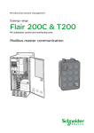
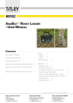
Requisite equipment
7
M etal
part
C onn ector on
com puter en d
8
M etal part
C onn ector on
F2 00C end
The equipment is configured using a PC provided with MS-DOS
and :
"Flair 200 Configuration and diagnostic" software,
Connection cable
Running the configuration program
Connect the cable to serial port 1 (COM1) of the computer and
to the serial connector of FLAIR 200C.
Start the PC under Windows and insert the "Easergy" CD-Rom.
The configuration program is run. Select the start menu.
The main menu appears.
Comments concerning use of the software :
Following modifications, the configuration data are only
acknowledged by the equipment after validation in the "OK" zone.
During modifications and before the validation operation, the
equipment runs with the previous data, which are therefore at
least partially different from the data momentarily displayed on the
screen.
Action in the "Cancel" zone displays the old parameters again.
The zone in which the cursor is positioned is highlighted.
To move between zones (data input fields or function title), the
"arrow keys" or "tabulation" key are used.
To select a highlighted zone, the "Enter" or "Space" keys are
used.
Schneider Electric
Easergy FLAIR 200C – DNP 3.0 Communication NT00138EN-01.doc
4
F200C DNP 3.0 Communication
Parameter values are modified using:
the "+" or "Space" keys to increase the value,
the "-" key to reduce the value.
When a parameter value is at its maximum, pressing the "+" or
"Space" key changes the value to its minimum. Pressing the "" key changes it back to the maximum.
To exit a sub-menu, the user presses the "Escape" key.
To exit the main menu, the user presses the "Alt" and "F4" keys
simultaneously.
Specific messages :
When the configuration software is started up, several types of
message may appear on the screen:
"Unidentified Equipment connected": the serial link between
the configuration computer and the equipment to be configured is
not valid: check the connection cord, and the connection location
at the computer end.
Fault messages: related to a configuration loss or internal
problem.
Software configuration :
Pressing the F10 key accesses the software configuration menu.
The menu is used to modify:
display colors,
the serial port used.
Schneider Electric
Easergy FLAIR 200C – DNP 3.0 Communication NT00138EN-01.doc
5
F200C DNP 3.0 Communication
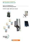
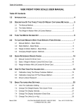
Main menu
MERLIN GERIN - Configuration and Diagnostic - ALT+F4=Exit DNP3 Setup:
RTU address
:
SCADA address :
DNP3 Parameters
PARAMETERS SETUP
Equipment name: f200c
SCADA address :
• May take every value between 0 and
65534.
• Default value is 0.
Measurement and fault detection
Alarm Parameters
Setup Time
Energy Preset
0
0
Modem Type: Direct RS 232
Communication Parameters
SAVE CONFIGURATION :
OK
Cancel
DNP3 Parameters :
Displays the configuration screen of
protocol dedicated parameters.
Modem type
• Defines the communication medium.
Possible values : Direct RS232 ,
Hayes, GSM, GPRS.
• In this exemple, default value is :
Direct RS232.
Easergy Flair 200C DNP3
PROM v1.00, PIC v2.08, Type: A
RTU address :
• May take every value between 0 and
65534.
• Default value is 0.
DIAGNOSIS
Display events
Display analog
Equipment states
Erase events
DNP3 Analyser
Alarm Parameters :
Displays the alarm configuration screen.
DNP3 Analyser :
Displays the trace of exchanges between the equipment and the
control station.
Communication Parameters (RS232,
Hayes and GSM only) :
Displays the communication medium
parameters setup screen according to the
medium selected.
MERLIN GERIN - Configuration and Diagnostic - ALT+F4=Exit Easergy Flair 200C DNP3
PROM v1.00, PIC v0.00, Type: A
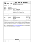
GPRS modem version :
GPRS Parameters (GPRS only) :
Displays the configuration screen of GPRS
dedicated parameters.
DNP3 Setup:
RTU address
:
SCADA address :
DNP3 Parameters
PARAMETERS SETUP
Equipment name: f200c
Measurement and fault detection
Alarm Parameters
Setup Time
Energy Preset
0
0
Modem Type: GPRS
GPRS Parameters
TCP/IP parameters
TCP/IP Parameters (GPRS only) :
Displays the configuration screen of
TCP/IP dedicated parameters
SAVE CONFIGURATION :
OK
Cancel
Default Config.
DIAGNOSIS
Display events
Display analog
Equipment state
Erase events
DNP3 Analyser
Schneider Electric
Easergy FLAIR 200C – DNP 3.0 Communication NT00138EN-01.doc
6
F200C DNP 3.0 Communication
Alarm Parameters
MERLIN GERIN - Configuration and Diagnostic - ALT+F4=Exit Alarm Parameters
Digital Input :
• For each Digital Input, the "yes" option
causes sending of an alarm on each
change of state of the input.
• Default value is no.
Digital input 1
Digital input 2
Digital input 3
Digital input 4
Digital input 5
Digital input 6
Flair 200C fault
:
:
:
:
:
:
:
no
no
no
no
no
no
no
Alarm message enabled : no
Dial up test :
no
Cyclic dial up :
Starting time (min) :
(hour) :
Period (hours)
:
no
0
0
24
Alarm on … :
• The "yes" option causes sending of an
alarm upon occurrence of the fault.
• Default value is no.
Alarm message enabled :
• The yes option activates alarm
transmission.
• Default value is no.
Note : Alarm call to the control station and
SMS sending can be enabled at the same
time. The SMS message is sent first.
Dial-up test:
• The "yes" option allows a test to be
performed on alarm transmission to
the control station. The Flair 200C is
calling the supervisor after recording of
the configuration.
• Default value is no.
Alarm on AC supply off detection :
Alarm on phase fault detection :
Alarm on earth fault detection :
no
no
no
Escape=Exit
Cyclic dial-up :
• The yes option causes cyclic dial-up to the control station.
• Default value is no.
Starting time (min & hour) :
• Starting time (in the following 24 hours) of the cyclic dial-up.
• Default value is midnight.
Period :
• Time interval between two consecutive cyclic dial-ups, from 0
to 255h.
• Default value is 24 hours
Communication Parameters
(RS232, Hayes or GSM modem type)
MERLIN GERIN - Configuration and Diagnostic - ALT+F4=Exit Modem : Direct RS 232
Host baud rate : 9600
Handle DSR : no
Handle DCD : no
Host baud rate:
• This is the transmission speed
between the SCADA and the RTU.
The available values are 200, 300,
600, 1200, 2400, 4800 and 9600
bauds
• The default value is set to 9600 bauds.
Handle DSR:
• Select "yes" if you want F200C to
detect connection, using DSR.
• Default value is "no".
Schneider Electric
Communication Parameters
Direct RS 232
Handle CTS
:
CTS delay
:
RTS (or CTS) to message delay :
Message to RTS delay
:
bauds
no
20ms
20ms
20ms
Escape=Exit
Easergy FLAIR 200C – DNP 3.0 Communication NT00138EN-01.doc
7
F200C DNP 3.0 Communication
Handle DCD:
• Select "yes" if you want F200C to
control reception with DCD.
• Default value is "no".
RTS (or CTS) to message delay:
• It's the delay F200C will wait after RTS (or CTS if handled)
before sending the message. Value is from 0 to 500 ms.
• Default value is 20 ms.
Handle CTS:
• Select "yes" if you want F200C to wait
for CTS after asserting RTS before
sending the message.
• Default value is "no".
Message to RTS delay:
• It's the delay F200C will wait after the end of the message
before asserting RTS low. Value is from 0 to 500 ms.
• Default value is 20 ms.
CTS Delay:
• It's the delay F200C will wait for CTS if
handled. Value is from 20 to 500 ms.
• Default value is 20 ms.
MERLIN GERIN - Configuration and Diagnostic - ALT+F4=Exit Communication Parameters
Hayes
Modem : Hayes
Host baud rate : 9600
Dialing type
: Tone
Host baud rate :
• This is the transmission speed
between the SCADA and the RTU.
The available values are 200, 300,
600, 1200, 2400, 4800 and 9600
bauds
• The default value is set to 9600 bauds.
bauds
Host tel number (main)
: 0478574532
Host tel number (standby) : 0478574532
Dial up delay time - first attempt : 1s
(0s = random value) - second attempt : 1mn
- third attempt : 2mn
Max transmission time : 10mn
Modem init : E0Q0V1&C1&D2S0=2
Factory modem init
Dialing type :
• Tone, pulse or none.
• The default value is tone.
Escape=Exit
nd
Host tel number (main) :
• Phone number of the control station
(maximum 15 digits).
• This field is empty in default settings
Host tel number (standby) :
• Standby number od the control station
if the main number is unavailable
station (maximum 15 digits).
• This field is empty in default settings
Dial up delay time :
Time lag between the occurrence of an
alarm and the call to the SCADA.
rst
1 attempt :
• Configurable from 0 to 60 s in
increments of 1 s.
• Default value : 1s.
The value 0 corresponds to a random time
lag between 1 and 60 s to avoid all the
equipment calling the SCADA at the same
time.
Schneider Electric
2 attempt :
In the event that the first call fails, time lag before the second call
to the SCADA.
• Configurable from 0 to 5 min in increments of 1 min.
• Default value : 1mn.
The value 0 corresponds to a random delay between 1 and 5 min.
rd
3 attempt :
In the event that the second call fails, time lag before the third call
to the SCADA.
• Configurable from 0 to 10 min in increments of 1 min.
• Default value : 2 mn.
The value 0 corresponds to a random delay between 1 and 5 min.
Maximum transmission time:
Maximum lasting time of a call. After this time, systematic call
break.
• Configurable from 1 to 30 min in increments of 1 min.
• Default value : 10 min.
Modem init :
• Hayes modem initialization chain (AT command)
• Default settings : E0Q0V1&C1&D2S0=2.
Factory modem init :
Restores the factory initialization chain
Easergy FLAIR 200C – DNP 3.0 Communication NT00138EN-01.doc
8
F200C DNP 3.0 Communication
MERLIN GERIN - Configuration and Diagnostic - ALT+F4=Exit GSM
Host baud rate :
• This is the transmission speed
between the SCADA and theRTU. The
available values are 200, 300, 600,
1200, 2400, 4800 and 9600 bauds
• The default value is set to 9600 bauds.
PIN code:
• PIN code of the SIM card.
• Default value : 0000.
In the event of an incorrect PIN code, “PIN
code error” appears in the “Equipment
states” menu.
Important: after three incorrect attempts
the SIM card becomes invalid. To make
it valid, a mobile phone must be used
(The Flair 200C cannot do this).
Please, consult the user guide of the SIM
Card to return to an available status.
Alarm Parameters :
Host tel number (main) :
• Phone number of the control station
(maximum 15 digits).
• This field is empty in default settings
Host tel number (standby) :
• Standby number od the control station
if the main number is unavailable
station (maximum 15 digits).
• This field is empty in default settings
Dial up delay time :
Time lag between the occurrence of an
alarm and the call to the SCADA.
rst
1 attempt :
• Configurable from 0 to 60 s in
increments of 1 s.
• Default value : 1s.
The value 0 corresponds to a random time
lag between 1 and 60 s to avoid all the
equipment calling the SCADA at the same
time.
Schneider Electric
Communication Parameters
Modem : GSM
Host baud rate : 9600 bauds
PIN code : 0000
Alarm parameters
Host tel number (main)
:
Host tel number (standby) :
Dial up delay time - first attempt : 1s
(0s = random value) - second attempt : 1mn
- third attempt : 2mn
Max transmission time : 10mn
Short Message System : SMS
Short Message System enabled
: no
SMS service center phone number :
SMS user phone number
:
Escape=Exit
nd
2 attempt :
In the event that the first call fails, time lag before the second call
to the SCADA.
• Configurable from 0 to 5 min in increments of 1 min.
• Default value : 1mn.
The value 0 corresponds to a random delay between 1 and 5 min.
rd
3 attempt :
In the event that the second call fails, time lag before the third call
to the SCADA.
• Configurable from 0 to 10 min in increments of 1 min.
• Default value : 2 mn.
The value 0 corresponds to a random delay between 1 and 5 min.
Maximum transmission time:
Maximum lasting time of a call. After this time, systematic call
break.
• Configurable from 1 to 30 min in increments of 1 min.
• Default value : 10 min.
Short Message System (SMS) :
SMS activated :
• Yes/No, enables SMS’s to be sent or not
• Default value is no.
SMS service center phone number :
• Phone number of the SMS server (refer to the notice with the
SIM card)
• This field is empty in default settings.
SMS user phone number :
• Mobile phone number of the recipient of the SMS’s
• This field is empty in default settings.
Easergy FLAIR 200C – DNP 3.0 Communication NT00138EN-01.doc
9
F200C DNP 3.0 Communication
GPRS Parameters
(GPRS version only)
MERLIN GERIN - Configuration and Diagnostic - ALT+F4=Exit PIN code:
Setting of the PIN code into the SIM card
(default value is 0000).
In case of wrong PIN code, "SIM card
failure" appears in the screen "Equipment
states".
Important: after three incorrect attempts
the SIM card becomes invalid. To make
it valid, a mobile phone must be used
(The Flair 200C cannot do this).
Please, consult the user guide of the SIM
Card to return to an available status.
APN Server:
Enter the APN(Access Point Name) which
you obtain from your GPRS provider
APN Login and Password:
Enter the login and the password provided
with your GPRS account.
Note: In major case, no login and
password are required for GPRS access.
GPRS Parameters
SIM CARD PARAMETERS
PIN code : 0000
GPRS COMMUNICATION PARAMETERS
APN Server (Max 30 Digits)
APN Login (Max 30 Digits)
APN Password (Max 30 Digits)
:
:
:
Time between connection attempt:
internet-entreprise
5mn
Escape=Exit
Time between connection attempt :
Delay time between 2 failed connection attempts to the IP network
TCP/IP Parameters
(GPRS version only)
MERLIN GERIN - Configuration and Diagnostic - ALT+F4=Exit Local Port:
Enter the port number you want F200C to
listen to incoming TCP connection. Value
is from 1 to 65535.
Max transmission time:
Maximum duration of a TCP/IP connection.
On time-out expiry, the TCP/IP connection
is closed.
Each time the F200C receives a request,
the timer is re-armed.
Schneider Electric
F200C PARAMETERS
Host address:
The address of the F200C is currently
allocated dynamically (0.0.0.0 corresponds
to dynamic allocation). The allocated
address is readable in Equipment State
menu. This field should be writable in
future use
Listen Mode:
Select yes, if you want F200C to listen to
incoming TCP connection. When the
equipment is in alarm mode, F200C stops
listening to incoming connection.
TCP/IP parameters
F200C Parameters
Host address(0.0.0.0 if dynamic)
Listen mode
Local port(1-65535)
Max transmission time
TCP connect. delay - 1st try
(0s = random value) - 2nd try
- 3rd try
SCADA PARAMETERS
IP address
Socket type
Remote port(1-65535)
:
:
:
:
0.0.0.0
yes
20000
10mn
:
:
:
1s
1mn
2mn
:
:
:
192.168.1.13
TCP
2404
Escape=Exit
TCP/IP connect. delay:
Time to send an alarm configured with "delayed" option:
•
first attempt: adjustable from 0 to 1min. per steps of 1s.
Setting it to ‘’0’’ selects a random time between 0 and 1 min
(this is mandatory to prevent all equipment calling the SCADA
at the same time).
•
second attempt: configurable from 0 to 5min. per steps of
1min. Setting it to ‘’0’’ selects a random time between 0 and 5
min.
Easergy FLAIR 200C – DNP 3.0 Communication NT00138EN-01.doc
10
F200C DNP 3.0 Communication
SCADA Parameters
•
third attempt: configurable from 0 to
10 min, in steps of 1 min. Setting it to
‘’0’’ selects a random time between 0
and 10 min
Note: The 2nd and 3rd emissions are only
used by the equipment if the preceding
one did not manage to send the frame.
Ip address :
Enter the Ip address of the SCADA
Socket type:
Not implemented(for future use).
Remote port:
Enter the port number the SCADA listens to incoming connection.
MERLIN GERIN - Configuration and Diagnostic - ALT+F4=Exit DNP3 Parameters
Idle line delay :
It's the minimum line idle interval between
two consecutive frames. Values are from
10 to 100 ms.
• 10 ms is the default value.
Requires Data Link Layer Confirm :
• Select "yes" if you want User Data to
be sent using a "SEND – CONFIRM
expected" frame type by the Link
Layer. Selecting "no" configures Link
Layer to use a "SEND – NO REPLY
expected" frame type for User Data
transmission.
Notice that in the case where "SEND –
NO REPLY expected" frame type is
used F200C will never send "RESET
of remote link" frames. It will work
strictly as a slave.
• Default is "yes".
Maximum Data Link Re-tries :
• Defines the number of re-tries by the
Link Layer, when the RTU doesn't
receive any "CONFIRM" frame (ACK
or NACK) to a frame using a "SEND –
CONFIRM expected" frame type.
When the Maximum Data Link Re-tries
is reached without confirmation, Link
Layer will perform "RESET of remote
link" to re-initialise the link.
• Default value is 3.
Time-out :
• It's the delay Link Layer will wait for a
"CONFIRM" frame after sending a
"SEND – CONFIRM expected" frame.
Values are from 1 to 10 s.
• Default value is 5 s.
Schneider Electric
DNP3 Parameters
LINK LAYER
Idle line delay
Requires Data Link Confirm
Maximum Data Link Re-tries
Time-out
Delay before emission
:
:
:
:
:
10ms
no
3
5s
10s
APPLICATION LAYER
Handle requested object(s) unknown bit
Sends Unsolicited Responses
Wait delay
Requires Application Confirm
Maximum Application Re-tries
Time-out
Transmission of currents on changes
Deadband value
:
:
:
:
:
:
:
:
yes
no
100ms
no
3
1mn
yes
10
Escape=Exit
Delay before emission :
• To avoid collision when spontaneously emitting on a halfduplex link, F200C will wait a T delay after seeing the link is
no more busy (using CD). If at this moment, CD is still not
present, F200C will send the message. If present, it will wait
another T delay. T delay is the sum of "Delay before
emission" and a random value. Configured values are from 0
to 10 s.
• Default value is 0 s.
Transmission of currents on changes :
• You can permit or inhibit transmission of currents
measurements on changes by selecting respectively "yes" or
"no".
• Default value is "yes".
Deadband value
• It's the difference there must be between last reported value
and current value to have a Change Event generated. Range
is from 1 to 10 000 in increments of 1.
• Default value is 10
Easergy FLAIR 200C – DNP 3.0 Communication NT00138EN-01.doc
11
F200C DNP 3.0 Communication
MERLIN GERIN - Configuration and Diagnostic - ALT+F4=Exit Fault passage indicator:
Phase fault
Earth fault
Equipment State
The equipment states menu is used to
display the information linked to the state
of the F200C.
Fault passage indicator
Faults are indicated in reverse video
Equipment States
Current states are indicated in reverse
video
Digital inputs:
DI 1
DI 2
DI 3
DI 4
DI 5
DI 6
Modem state :
TCP Connected !
Ip address :
193.249.197.190
Escape=Exit
Digital Outputs
Use the “S” (select), “C” (confirm) and “A”
(cAncel) keys to control the relay outputs
Digital Inputs
Inputs in logical state 1 are indicated in
reverse video
Modem not identified: F200C was unable
to
communicate with the modem used.
Modem state
comments
Modem Init...
Entering code pin...
Code pin error !
Network
registration...
GPRS registration...
PDP Init...
PDP Closing...
PDP Status...
PDP Connected !
G200 is configuring the modem
Wrong code pin
IMSI registration
Closing TCP listened
TCP Closing...
TCP Listening...
TCP Listened !
GSM SIM card failure: F200C has detected
the embedded GSM modem card, but
cannot read the SIM card.
TCP Connecting...
TCP Connected !
Modem failure !
GSM registration
denied !
Ip address (GPRS only): Indicates the
current Ip address of the F200C.
GSM signal quality
Specific to the GSM modem, the barchart
indicates the quality of the reception signal
Open a PDP session
Close the PDP session
Check the PDP status
Stand-bye state when listen mode is
not activated.
Close the listen port
Disconnection from the SCADA
Opening the listen port
Stand-bye state when listen mode is
activated.
Try to connect to the SCADA
Connected to the SCADA
IMSI registration is refused by the
operator (check your SIM card right
with your provider)
GPRS registration or PDP activation is
refused by the operator (check your
SIM card right with your provider)
GPRS registration
denied !
MERLIN GERIN - Configuration and Diagnostic - ALT+F4=Exit 31:43.16 >>.......... 05 64 4F 44 00 00 00 00 03 C5
Schneider Electric
GSM signal quality:
The signal must be between 17 and 31 (0 at start, 99 is faulty)
0
Max(31)
received signal: 0
This analyser shows the different frames
recognised with some complementary
information such as the direction of the
frame (Host -> F200C or F200C -> Host),
possibly the error detected (character
framing error, overflow, checksum, bad
length, bad control character). In case of
multiple errors, it's the first one that is
indicated.
Each correct frame is shown, one block
per line (10 bytes for the first one, 18 bytes
for next ones, last one may be shorter).
DO Controle: Select
Confirm command
cAncel command
Communication state:
Modem not identified
SIM card failure
Digital outputs:
-----[|]-----> DO1
-----[|]-----> DO2
Equipment state:
Flair 200C fault
Local conf
Remote conf
Config. fault
Alarm processing...
AC supply off
DNP3 Analyser
Equipment state
55:52.99 < ..........
55:53.00 >>..........
55:55.09 < ..........
55:55.10 >>..........
55:57.20 < ..........
55:57.21 >>..........
55:57.69 < ..........
55:57.78 >>..........
C7
00
00
05
E0
05
E5
05
E1
05
E6
05
E2
05
E7
05
E3
05
E8
00
04
C7
06
01
64
C4
64
C4
64
C5
64
C5
64
C6
64
C6
64
C7
64
C7
06
01
81
01
18
11
01
0A
81
11
01
0A
81
11
01
0A
81
0B
01
4F
81
01
5E
90
00
FC
C4
3C
44
90
C4
3C
44
90
C4
3C
44
90
C4
3C
44
90
98
01
00
00
01
00
02
00
02
00
02
00
02
00
02
00
02
00
01
00
00
04
01
01
01
86
00
06
00
4F
00
06
00
AD
00
06
00
EA
00
06
00
01
01
8A
01
00
13
00
3C
00
2B
00
3C
00
8C
00
3C
00
A5
00
3F
00
01
88
13
00
00
1E
00
03
00
00
01
01
CE
06
F7
17
00
00
83
3C
93
07 02 00 1E 02 00 16 82
00 01 00 00 01 00 F2 60
07 0A 01 F6 08 00 73 B9
04 06 95 9D
00 CE 83
03 06 3C 04 06 FC 67
00 F7 93
00 CE 83
03 06 3C 04 06 3E 24
00 F7 93
00
DB
00
00
04
1E
64 47
03
00
01
01
C5
17 07 02 00 1E 02 00 9A D4
8F 04 01 92 05 01 8F 49 2A
00 07 0A 01 DA 08 00 C0 17
Pause...
Easergy FLAIR 200C – DNP 3.0 Communication NT00138EN-01.doc
12
F200C DNP 3.0 Communication
! "# $
&'(
%
"# $
%'*+ ,-
Device Profile Document
)
& . /00 !- $
&'( )/ (-' $
) ! 1/ ,-,$
",-!
."&
) ! ,0 , ,$
-"2. 23(-,45/ (-' ,4" !1/".'5'!,,/00 !- ' " '-' - -+ %'*+ ,( #0.- .',-', ,(!'2 ' -+ "--"(+ -"2.7 $
•
•
•
•
8'"!9'0/-: .. "!'"-' ,$ " "..0 '-,
8'"!9( / -!; .. "!'"-' ,$ " "..0 '-,
".*'0/-: .. "!'"-' ,$ " "..0 '-,
".* /-0/-: .. "!'"-' ,$ " "..0 '-,
"<'#/# "-" '=)!"#
!" ,#'-- $
'> 6 (--,7 $
?
"<'#/# 00.'("-' )!"*# - '> 6 (--,7 $
!" ,#'-- $
( '& $
( '& $
"<'#/# "-" '=
6 7
?6
7
?@
6#/,-2 ? 7
:-!',$
)'< "-AAAA
5'*/!"2.4!" *
6 7
& ., /00 !- 6-+
"<'#/# 00.'("-'
-
6 7
"9 ! :-!',$
)'< "-AAAA
5'*/!"2.4!" *
-
6 7
"2.," "00.'("-' 5!"*# -- ( -"' "..(.",, "-"6'(./ '* <0" ,' 45/-/! /, " !, !& 0 '-,7 "
& - 23(-,6( !!,0 '*- & -2/55!("0"('-97
(".( 5'*/!"-' B'-+"
Schneider Electric
Easergy FLAIR 200C – DNP 3.0 Communication NT00138EN-01.doc
13
F200C DNP 3.0 Communication
1/'!, "-" '= "9 !
&!
.B"9,
# -'# ,
5'*/!"2.6
1/'!, 00.'("-'
5'!#"-' $
7
"9 !
5'!#"-' $
&!
.B"9,6 -!( ##
7
C + !0 !-'* & - "-"6 ."& &'( , .97
C + , '*#/.-':5!"*# -!,0 , ,6 ."& &'( , .97
# -'# ,
5'*/!"2.6
5D # -'# ,D
4B+ EAAAAAAAAAAAAAAAAAAAAAAAAAAAAAAAAAAAAA
7
'# /-,B+'. B"'-'*5 !$
"-" '=
5'!#
#0.- 00.)!"*# 00.'("-'
5'!#
#0.- 00. ,0 ,
)'<
)'<
)'<
)'<
"-AAAA
"-AAAA
"-AAAA
"-AAAA
"!'"2.
"!'"2.
"!'"2.
"!'"2.
5'*/!"2.6
5'*/!"2.
5'*/!"2.6
5'*/!"2.
7
7
-+ !,AAAAAAAAAAAAAAAAAAAAAAAAAAAAAAAAAAAAAAAAAAAAAAAAAAAAAAAAAAAAAAAAAAAAA
, < (/-,
C
-! . 0 !"-' ,$
8'"!9 /-0/-,
&!
&!
&!
&!
.B"9,
.B"9,6 7
.B"9,6F7
.B"9,6F7
#
#
#
#
-'#
-'#
-'#
-'#
,
,
,
,
5'*/!"2.
5'*/!"2.
5'*/!"2.
5'*/!"2.
/ -H
/.,
/., 55
"-(+
"-(+ 55
&!
&!
&!
&!
&!
.B"9,6F7
.B"9,6 7
.B"9,6 7
.B"9,6 7
.B"9,6 7
#
#
#
#
#
-'#
-'#
-'#
-'#
-'#
,
,
,
,
,
5'*/!"2.
5'*/!"2.
5'*/!"2.
5'*/!"2.
5'*/!"2.
//
."! / /
&!
&!
.B"9,
.B"9,
# -'# ,
# -'# ,
5'*/!"2.
5'*/!"2.
;
6 7
6 7
6F7
G
(".( 5'*/!"-' B'-+"
< (/-,",'-+",2 !( '&
.B"9, < (/-,"I /.,
IB'-+I :-'# IJ ,
Schneider Electric
Easergy FLAIR 200C – DNP 3.0 Communication NT00138EN-01.doc
14
F200C DNP 3.0 Communication
0 !-,8'"!9 0/- +" *
&"!'"-' !1/ ,- $
& -,B+
,0 ('5'(
&!
.9-'# :-"**
.9 :-'# :-"**
5'*/!"2. - , 2 -+4
-+ !6"--"(+ <0." "-' 7
,
, .'('-
0 !-,-'# :-"** 8'"!9 0/- +" *
,0 ('5'(&"!'"-' !1/ ,- $
&!
8'"!9 0/- +" * C '-+ '#
8'"!9 0/- +" * C '-+ ."-'&
5'*/!"2. 6"--"(+ <0." "-' 7
!-+
,0 , ,$
& -,B+
, -"-'( "-"'
&!
5'*/!"2. 6"--"(+ <0." "-' 7
.9( !-"' 23(-,
# -'# ,6"--"(+ <0." "-' 7
, .'('-
'#
,0 , ,$
&!
C+
&'( ,-"!-,
C + -"-/,)."*, +" *
-+ ! 0-' ,0 !#'--
8
)/ (-' (
8
,,/00 !-
5"/.- / -! 23(- "!'"-' $
/ -!,
/ -!, 0 !5'*/!"2. 6"--"(+ <0." "-' 7
5"/.- 23(5"/.- "!'"-'
'-:29:0 '-.',-"--"(+
, /.-':)!"*# - ,0 , ,$
Schneider Electric
.. & !"-$
/ -!, 0 !5'*/!"2. 6"--"(+ <0." "-' 7
8'-,
8'-,
-+ ! "./ AAAAAAAAAAA
'-:29:0 '-.',-"--"(+
,
Easergy FLAIR 200C – DNP 3.0 Communication NT00138EN-01.doc
15
F200C DNP 3.0 Communication
Implementation Table
OBJECT
!
Description
"#
$%
!&
&%
!&
'(
$%
!&
&%
!&
'(
8'"!9 0/-; .. "!'"-' ,
8'"!9 0/-
?
8'"!9 0/-B'-+ -"-/,
?
8'"!9 0/- +" * B'-+ '#
?
-! . ."9 /0/-8.(=
8'"!9
F4
4@
?
(+ 5
!1/ ,-
/ -!; .. "!'"-' ,
:8'-8'"!9
/ -!
?
".* 0/-; .. "!'"-' ,
:8'- ".* 0/-
?
:8'- ".* 0/-
?
:8'- ".* +" *
& -B'-+ '#
?
".* /-0/- -"-/,; .. "!'"-' ,
F
:8'- ".* /-0/-8.(=
F4
4@
:8'- ".* /-0/-8.(=
F4
4@
'# "
"-
6,
7
@
B+ !
1/" -'
-9J
.",,
"-"
.",,
"-"
4 4@
.",,
"-"
4 4@
6 7
.",,
"-"
4 4@
6 7
-! ".
'("-' ,
' <J
23(23(-
'-' - %'*+ ,-
6,
7
& ., /00 !-
(7) : RESPONSE TO THIS REQUEST IS OBJECT UNKNOWN
Schneider Electric
Easergy FLAIR 200C – DNP 3.0 Communication NT00138EN-01.doc
16
F200C DNP 3.0 Communication
Description
$& (
6+ < (7
)
*%
**
!$
"#
%
)
$
* *!$
"#
!*$
%
-! . ."9
/0/-8.(=
-! . ."9
/0/-8.(=
-! . ."9
/0/-8.(=
-! . ."9
/0/-8.(=
'*'-". /-0/'*'-". /-0/!, -
!*9
, - 5)"/.- ",,"*
'("-!
Control relay output block :
0 and 1 : Command of digital output 1 and 2.
2 : Loading of the meter Energy with the preset energy value (32 bits) on closing order.
3 : Fault passage indicator reset on closing order.
Description
$& (
6+ < (7
)
"#
8'"!9
8'"!9
8'"!9
8'"!9
8'"!9
8'"!9
8'"!9
8'"!9
8'"!9
8'"!9
8'"!9
8'"!9
8'"!9
8'"!9
8'"!9
8'"!9
8'"!9
8'"!9
8'"!9
8'"!9
8'"!9
8'"!9
8'"!9
8'"!9
0/0/0/0/0/0/0/0/0/0/0/0/0/0/0/0/0/0/0/0/0/0/0/0/-
Schneider Electric
F F
@ @
? ?
8
)
F
@
?
F
*%
* *!$
%
-"-/,
-"-/,
-"-/,
-"-/,
-"-/,
-"-/,
-"-/,
-"-/,
-"-/,
-"-/,
-"-/,
-"-/,
-"-/,
-"-/,
-"-/,
-"-/,
-"-/,
-"-/,
-"-/,
-"-/,
-"-/,
-"-/,
-"-/,
-"-/,
)
$
* *!$
"#
C '-+
C '-+
C '-+
C '-+
C '-+
C '-+
C '-+
C '-+
C '-+
C '-+
C '-+
C '-+
C '-+
C '-+
C '-+
C '-+
C '-+
C '-+
C '-+
C '-+
C '-+
C '-+
C '-+
C '-+
%
'#
'#
'#
'#
'#
'#
'#
'#
'#
'#
'#
'#
'#
'#
'#
'#
'#
'#
'#
'#
'#
'#
'#
'#
Easergy FLAIR 200C – DNP 3.0 Communication NT00138EN-01.doc
!*$
'*'-". 0/'*'-". 0/'*'-". 0/'*'-". 0/'*'-". 0/-F
'*'-". 0/, !&
, !&
)."'!
5"/.(".( 5'*/!"-'
# - ( 5'*/!"-'
, !&
5'*/!"-' 5"/.-"(=@ K
& -.,,
, !&
"!-+5"/.)/*'-'& "!-+5"/.,/00.9 550+",
+", 5"/.)",-0+", 5"/., !&
, !&
, !&
17
F200C DNP 3.0 Communication
Description
$& (
6+ < (7
)
"#
*%
* *!$
".* 0/-
%
:8'-
".* 0/-
:8'-
".* 0/-
:8'-
".* 0/-
:8'-
".* 0/-
:8'-
".* 0/-
F F
0/0/0/0/-
Description
$& (
6+ < (7
)
@ @
? ?
$& (
6+ < (7
)
%
:8'C '-+ '#
:8'C '-+ '#
:8'C '-+ '#
:8'C '-+ '#
:8'C '-+ '#
+", (/!! +", (/!! +", (/!! % # 0 ."!(/!! & !"* (/!! - # "
$& (
6+ < (7
)!1/ (9
)
* *!$
!*$
%
.-"* 0+",
(-'& 0 B !
"(-'& 0 B !
00"! -0 B !
)
$
"#
* *!$
!*$
%
!*9
+
"#
$
"#
*%
* *!$
%
:8'-
8'"!9( / -!
,
".* /-0/-
%
:8'-
".* /-0/-
:8'-
".* /-0/-
:2'-
".* /-0/-
:2'-
Schneider Electric
!*$
B !5"(-!9
*%
* *!$
%
:8':8':8':8'-
"#
Description
"#
* *!$
:8'-
"#
".*
".*
".*
".*
$
:8'-
".* 0/-
Description
)
"#
!*$
%
:8'C '-+ /'#
:8'C '-+ /'#
:8'C '-+ /'#
:8'C '-+ /'#
Easergy FLAIR 200C – DNP 3.0 Communication NT00138EN-01.doc
9(.'( '"./00 !'
!*90!, -&"./
)
6
" !,,
& !,'
.97
6!"
.95 !5/-/! /, 7
6
" !,,
& !,'
.97
18
F200C DNP 3.0 Communication
Analog output 0 : Cyclic dial period
The Flair 200C may periodically dial up. This function can be used to check if the equipment is still running and to
download measurements. The parameters of the cyclic dial up are coded as follows :
Most significant byte :
Set
0
Hour (0 to 24)
B15
0
B8
Minute (0 to 59)
B7
B0
Set = 1 : Cyclic dial up process is on (only if alarms are activated).
Set = 0 : Cyclic dial up process is off.
Hour and Minute stand for the starting time of the process in the current day.
Least significant byte :
0
B15
Period (0 to 255 hours)
B8
B7
B0
Period stands for the number of hours between two automatic calls.
Analog output 2 and 3 : IP addresses (for GPRS only)
F200C IP address: IP address of the F200C (must be 0.0.0.0 if dynamic allocation is used)
SCADA IP address: IP address of the SCADA
Each byte can be : 0 <byte < 255
For instance, 193.251.9.68 is coded as :
68 / 0x44
9 / 0x09
251 / 0xFB
193 / 0xC1
Schneider Electric
byte 1
byte 2
byte 3
byte 4
Easergy FLAIR 200C – DNP 3.0 Communication NT00138EN-01.doc
19
F200C DNP 3.0 Communication
Description
$& (
6+ < (7
+
"#
".* /-0/".* /-0/-
F F
,
%
:8':8'-
".* /-0/-
:8'-
".* /-0/-
:8'-
".* /-0/-
@ @
:8'-
".* /-0/-
? ?
:8'-
".* /-0/".* /-0/-
:8'8
:8'-
".* /-0/-
:8'-
".* /-0/-
:8'-
"#
!*$
%
:8'C '-+ /- '#
:8'C '-+ /- '#
:8'C '-+ /- '#
:8'C '-+ /- '#
:8'C '-+ /- '#
:8'C '-+ /- '#
:8'C '-+ /- '#
:8'C '-+ /- '#
:8'C '-+ /- '#
:8'C '-+ /- '#
."!#,
B !- 55-+!,+ .
B!
-+!,+ .
#"<-+!,+ .
-+!,+ .
, -5"/.--'#
#"<5"/.-"(= -'#
5"/.-"(= -'#
)."'!
6
6
0 !.97
0 !.97
Analog output 4 : Alarms on TSS
1 = Alarm is ON if the TSS is ON
0 = Alarm is not used
Alarme
1
2
3
4
5
6
7
8
9
10
11
12
13
14
15
16
Analog output 4 : alarms on TSS
Désignation
Digital input 1
Digital input 2
Digital input 3
Digital input 4
Digital input 5
Digital input 6
Flair 200C fault
Test alarm
Short message system enabled
Reserved
AC supply off
Phase fault
Earth fault
Alarm message set up
Reserved
Reserved
Schneider Electric
Bit
0
1
2
3
4
5
6
7
8
9
10
11
12
13
14
15
Easergy FLAIR 200C – DNP 3.0 Communication NT00138EN-01.doc
20
F200C DNP 3.0 Communication
Analog output 5 to 11 :
Analog Output index
(decimal value)
5
6
7
8
9
10
11
Parameter of measurements range
Parameter
min
Power off threshold
Power on threshold
Imax threshold
I0 threshold
Reset fault time
Imax fault ack. time
I0 fault ack time
5
70
40
20
1
40
20
max
95
120
750
160
12
800
800
Incremental
value
1
1
1
1
1
1
1
unit
%
%
A
A
h
ms
ms
Analog output 12 and 13 : F200C and SCADA ports (for GPRS only)
F200C port : local port on which F200C is listening to incoming connections (only if local parameter listen mode
is <ON>)
SCADA port : remote port on which the SCADA is listening to incoming connections from F200C
Possible values: 1 to 65535
Schneider Electric
Easergy FLAIR 200C – DNP 3.0 Communication NT00138EN-01.doc
21
F200C DNP 3.0 Communication
Special considerations
Internal INdications
Control center time synchronization
Bit 4 of first IIN byte is set when F200C starts up. This bit is cleared when the SCADA sends its first clock
synchronization message.
Then F200C sets it again regularly (every hour) to ensure the SCADA is answering it on a regular basis.
This clock synchronization is required to ensure a proper accuracy of time-stamping process. Should F200C not
receive a new synchronization message from the master within an hour after the last one, the IIN bit is set.
Schneider Electric
Easergy FLAIR 200C – DNP 3.0 Communication NT00138EN-01.doc
22
Schneider Electric SA
NT00138EN-01.doc Edition : 09/2006
Schneider Electric
64-70, avenue Jean-Baptiste
Clément
F- 92646 Boulogne Billancourt
Cedex
Tel.: +33 (0)1 46 99 70 00
Fax: +33 (0)1 46 99 71 00
http://www.schneider-electric.fr
Due to changes in standards and equipment,
the characteristics mentioned in the texts and images of this
document cannot be considered as binding unless confirmed
by our services.
Publication: Schneider Electric Industries SA
Easergy FLAIR 200C – DNP 3.0 Communication NT00138EN-01.doc
23