1
94276E-02
2008-02
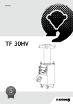
FLEXIT L4 X
L7 X
Operating Instructions
Air Handling Unit - Cross
Innhold
1
2
3
4
5
6
8
9
10
11
12
13
14
15
Sizes/Physical Dimensions
1.1 Dimensions L4 X
1.2 Dimensions L7 X
Installation
2.1 Inspection/Maintenance
2.2 Space Required
2.3 Recommended Location/Sound Insulation
2.5 Drainage
Connections
Electrical Works
4.1 Automatics
4.2 Supply Air Temperature Sencor (B1)
4.3 Temperature sensor water battery (B5)
4.4 External Components
Plumbing Works
5.1 Techncal Data Water Batteries (Tansformer and EC)
5.2 Possible Valve Types
5.3 Possible Valve Motor
5.4 Connections
General Drawings and System Drawings
6.1 L4 XE and L7 XE
6.2 L4 XW and L7 XW
7
Capasity and sound data
7.1 Capacity Diagram, Sound Data, Specifications - L4 XE (Transformer regulation)
7.2 Capacity Diagram, Sound Data, Specifications - L4 XE EC
7.3 Capacity Diagram, Sound Data, Specifications - L7 XE (Transformer regulation)
7.4 Capacity Diagram, Sound Data, Specifications - L7 XE EC
Technical Specifications
8.1 Technical Specifications L4 X
8.2 Technical Specifications L7 X
Final Check
Important Safety Instructions
Functional Decription
11.1 Heating Elements
Cleaning - Maintenance L4 X/L7 X
Fault Location
CE Declaration of Conformity
Product/Environmental Declaration
2
4
4
4
5
5
5
5
5
6
6
6
6
6
6
7
7
8
8
8
9
9
10
11
11
12
13
14
15
15
15
16
17
17
17
18
20
21
22
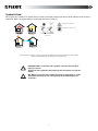
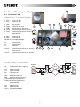
Symbols Used
This product has a number of symbols that are used to label the product itself and in the installation and user documentation. Here is an explanation of some of the commonest symbols
DANGER! ELECTRICITY
DANGER! DO NOT TOUCH
SUPPLY
EXTRACT
EXHAUST
OUTDOOR
EXCHANGER/SUMMER
CASSETTE
Our products are subject to continuous development and we therefore reserve the right to make changes.
We also disclaim liability for any printing errors that may occur. .
!
CAUTION: When a text bears this symbol, it means that personal
injury or serious
damage to the equipment may follow if the instructions are not followed.
NB: When a text bears this symbol, damage to equipment or a poor
utilisation ratio may be the consequence of not following the instructions.
3
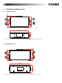
1
Sizes/Physical Dimensions
1.1
Dimensions L4 X
*Mål i mm
OBS: The units have doors on each side so that they can be operated from either side.
1.2 Dimensions L7 X
*Mål i mm
OBS: The units have doors on each side so that they can be operated from either side.
4
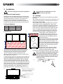
2
Installation
Check that the installed unit has a fall
towards the drainage outlet.
The unit is designed for indoor installation.
2.1
Inspection/Maintenance
2.5 Drainage
The unit must be installed with space for service and
maintenance such as filter replacement and cleaning
the fans and recovery system. It is also important
for the unit to be located so that the electrical
cabinet is easily accessible for electrical connection,
troubleshooting and future component replacement.
The drainage system must be installed by a qualified
plummer.
The condensated water must be lead to the nearest air
valve for discharge water, drainage from wash basin/
dishwasher or floor outlet.
This connection mus always be placed in a frost free
environment and be completed with a water lock
(enclosed). A water lock MUST be installed or this will
lead to the drainage system not functioning due to
under pressure in the ventilation unit. Make sure that
there is a height differeanse between the drainage
outlet and the water lock/drainage pipe, in order for
function properly (see Fig. 3). You must use 15 mm
copper pipes, with a minimum fall of
5°, avoiding if possible cold rooms. In
could rooms the drainage pipe must be
insulated with at least 50 mm mineral
wool (drain bowls).
If the pipe cannot be lead directly down
from the unit, it must be placed between
inner roof and insulation. If there is no
risk of frost the water lock may be placed
in the loft insulationand connected with
ventilation unit and breather pipe with
16mm plasic hose.
Condensation water pipe must never
be placed on top of the loft insulation
without installing heating cable
connected to the piping and proper outside insulation.
2.2 Space Required
Type
A
B
L4 X
400 mm
500 mm
L7 X
500 mm
500 mm
A: In front/above unit
B: Distance from wall
Fig. 1
"
!
Space in front of unit: min. A-measures (se listing).
Space over unit: min. 50 cm. These are minimum
requirements that only take service needs into
account. National statutory requirements for
electrical safety may deviate from this. Check which
rules apply in your country.
Pour some water in the bottom of the ventilation unit so that the water lock is filled.
If the drainage system is not installed in accordance with prevailing standards water
leaks may occur.
2.3 Recommended Location/Sound Insulation
The unit is intended for installation in lofts, but may
also be mounted in other locations. The unit should
not be installed dirictly above sleeping rooms due to
potential noise problems. The unit should be placed on
a firm surface e.g. plaster or compound board in level
position. If the room is noise sencitive the floorboard
can be placed ontop of an additional firm piece of
insulation material for optimal muffeling (see Fig. 2).
Fig. 2
Fig. 3
Min 100 mm
waterlock
Must be room forat least 50 mm
insulation for drainage pipe, in
areas with frost condions
Additional floorboard
Additional insulation
Floorboard
Insulation
Recommended surface
5
Min 5° fall
Connections
4.1 Automatics
The control package is supplied with the unit. The lowvoltage cable must be laid between the unit and the
switch unit. See separate automatics documentation.
• The ducts usually come from joists and are
connected to the nipples on the top of the unit.
• Ensure that the ducts are connected to the
right nipple. See the labelling on the unit
(top/bottom and behind door). The symbols are
explained on page 3 and the placing is shown
on measurement drawing in Chap. 1.
• Pull the duct insulation well up to the unit.
• To avoid condensation, it is very important for
the outdoor air duct to have insulation and a
plastic sleeve pulled right down to the unit. Seal
the plastic sleeve to the unit with tape.
The outdoor air duct is normally designed with
25 mm insulation.
• Lay the outdoor air duct with a slight incline
towards the outdoor air cap so that any water
that enters drains out again.
• With a short distance between the unit and
the exhaust point, sound insulation must be
installed to meet the requirements for the outdoor sound level.
• Ducts must have good sound insulation, particularly above the unit.
4.2 Supply Air Temperature Sencor (B1)
Temperature sensor B1 must be placed after
the water battery.
This should be placed in the supply air duct (red on Flexit
Drawing/Symbold Used page 3) approx. 1 m from the
unit. Roll out the marked wire coil on the unit located
close to the supply air intake. Drill a Ø 7 mm hole in the
duct where the sencor can be placed. Seal the hole with
a sealant and tape the wire on the outside of the duct to
keep in place.
4.3 Temperature sensor for water battery (B5)
Electrical Works
In order to avoid that the water battery is destroyed
by frost a temperature sensor (B5) must be installed
on the return water pipe where the cold water leaves
the battery
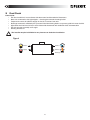
The unit should be equipped with a separate earth-leakage circuit-breaker.
Power Cord
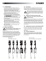
4.4 External Components
The unit is supplied with a 1.8 m cable and plug
(which also functions as the service switch). The
cable emerges on the top of the unit (front) on the
left side of a right model and the right side of a left
model. This is connected to a 230 V 50 Hz singlephase earthed power point that is located in an
easily accessible position close by.
For fuse types, see chap. 8.
Refer to separate electrical circut drawing enclosed
with the individual ventilation unit and Fig. 4 below.
All electrical connections must be made by qualified
personell only.
Water models
Connected to external box
Electrical models
Connected directely on the mainvboard
6
Damper motor 230V
2-wires
Vent motor 230V
3-way vent
Pump motor 230V
Damper motor 230V
2-wires
Damper motor 230V
3-wires
Fig. 4
Damper motor 230V
3-wires
4
The low-voltage cable must be laid at least
30 cm away from the 230 V cable. For flush
installation, lay the cable in 20 mm conduit
pipe.
B5 Temperature
sensor Water battery
3
WATERBATTERY
5
Plumbing Works
All plumbing work must be performed by an authorised
plumber.
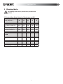
5.1 Techncal Data Water Batteries (Tansformer and EC)
Water temp. In °C
80
70
60
50
40
Water temp. Out °C
60
50
40
30
30
Water pressure l/s
0,06
0,05
0,04
0,03
0,05
Pressure drop waterside
kPa
8,30
6,12
4,18
2,48
8,53
Max battery capasity kW
4,6
3,8
3,0
2,5
2,2
Max temp. increase °C
39,1
32,4
25,6
18,6
18,6
Pipe connection Ø mm
10
10
10
10
10
Recommended kvs-value
1,0
1,0
1,0
1,0
1,6
Water pressure l/s
0,07
0,06
0,04
0,03
0,06
Pressure drop waterside
kPa
12,4
9,3
6,6
4,1
13,1
Max battery capasity kW
5,4
4,5
3,7
2,8
2,6
Max temp. increase °C
32,0
26,9
21,6
16,3
15,5
Pipe connection Ø mm
10
10
10
10
10
Recommended kvs-value
1,0
1,0
1,0
1,0
1,0
L4 XW
L7 XW
7
WATERBATTERY
5.2 Possible Valve Types
3-way valve, type Belimo DN15:
Article no.
56597 Kvs 1,6
Article no.
56604 Kvs. 1,0
5.3 Possible Valve Motor
Valve motor type Belimo L230A-SR, 0-10V.
Article no.
56596.
24V motor cannot be used
5.4 Connections
Use the recommended connection (see Fig. 18) unless
specified otherwise. The water supply must be at the
bottom of the water battery - the return must be on
the top.
Place the adjustment valve as close to the unit as
possible. (Please note that many valve motors can go
in both directions and this can be set on the motor.
Set it so that the valve opens on an increasing 0-10 V
signal.)
Vannbatteriene har ingen luftemulighet da
dette ikke har noen funksjon.
Om aggregatets vannbatteri er det høyeste
punktet i kretsen må luftningsventil monteres etter vannbatteriet
Hot water from
boiler system
3-way valve
If you use a water battery that has not had glycol
(or another antifreeze) added, the unit should be in
a heated room on account of the risk of frost in the
battery. Install air dampers with spring-loaded return
for outdoor air. Place the unit close to a gully to avoid
damage caused by any water leaks.
Pump
Throttle valve
B5
Water battery in the
supply air system
Fig. 18 Recommended connection
8
14
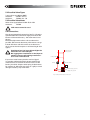
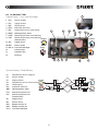
6 General Drawings and System Drawings
6.1 L4 XE and L7 XE
General Figure - Cross Heat Exchanger
1 (FI2)
Extract air filter
2 (FI1)
Supply air filter
3
4
5
6
Thermoguard
Preheater, electrical
7
Heating battery, electrical
Extract
Overheating thermostat heating
(B6)
(EB2)
(EB1)
(F20)
7 (F10)
Overheating thermostat heating
(manual reset)
8 (M1)
Supply air fan
9 (M2)
Extract air fan
10 (HR-X) Cross heat exhanger
3
1
12
11
2
4
15
Outdoor
Supply
11
Control panel
12
Control central
13
Drainage
14 (F11)
Overheating thermostat pre-heating
14
Exhaust
7
6
5
8
10
9
13
(manual reset)
15 (F21)
Overheating thermostat pre-heating
System Drawing - Electrical Battery
& &
Extract
B1
Temperature sencor, supply air
FI2
Extract air filter
FI1
& &
%"
F10\F11 Overheating thermostat
(manual reset)
M1
Supply air fan
M2
HR-X
Extract air fan
Cross heat exhanger
(28
"
-
Supply
9
Outdoor
&)
%"
"
Supply air filter
B6
Thermoguard
EB2
Preheater, electrical
EB1
Heating battery, electrical
F20\F21Overheating thermostat
&)
-
Exhaust
6.2 L4 XW and L7 XW
8
General Figure - Cross Heat Exchanger
1 (FI2)
Extract air filter
2 (FI1)
Supply air filter
3 (B6)
4 (EB2)
5 (B5)
Thermoguard
Preheater, electrical
Temperature sencor, water batter
6 (WB1)
7 (F20)
8 (F10)
Heating battery, water
Overheating thermostat preheating
Overheating thermostat preheating
Extract
(manual reset)
9 (M1)
Supply air fan
10 (M2)
Extract air fan
11 (HR-X) Cross heat exhanger
12
Control panel
13
Connector box
14
Drainage
3
1
13
12
2
4
7
8
Outdoor
Exhaust
Supply
9
5
6
11
14
10
System Drawing - Water Battery
B1
Temperature sencor, supply air
FI2
Extract air filter
FI1
B5
Avtrekk
Supply air filter
Temperature sencor, water battery
B6
EB2
WB1
F20
Thermoguard
Preheater, electrical
Heating battery, water
Overheating thermostat
F10
Overheating thermostat
(manual reset)
M1
Supply air fan
M2
DA1
DA2
HR-X
Extract air fan
Damper, extract air
Damper, outdoor air
Cross heat exhanger
& &
&)
"
(28
"
%"
"
Tilluft
-
10
-
7"
Uteluft
&)
$!
$!
Avkast
7
Capasity and sound data
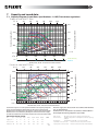
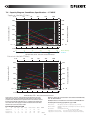
7.1
Capacity Diagram, Sound Data, Specifications - L4 XE (Transformer regulation)
Supply air side (with F7 filter)
20
40
100
80
60
120
400
200
300
150
Power consumption in Watt
Contact resistance (Pa)
l/s 0
230V
100
200
190V
170V
150V
120V
105V
85V
60V
100
230V
190V
170V
150V
77dB(A)
77dB
(A)
75dB(A)
75dB
(A)
120V
85V
60V
105V
50
70dB(A)
70dB
(A)
65dB(A)
65dB
(A)
0
Pa 0
100
200
300
400
500
0
-5
-15
-30
-50
-75
0
15
30
40
55
65
m3/h 0
W
Water Battery
Pa
F5 Filter
Air flow rate, m3 /h - Pressure correction factor
Extract air side (with F7 filter)
20
40
100
80
60
120
400
200
300
150
230V
230V
200
100
190V
170V
190V
170V
150V
120V
105V
85V
60V
100
58dB(A)
150V
55dB(A)
50
120V
50dB(A)
105V
85V
45dB(A)
60V
0
Pa 0
m3/h 0
100
Power consumption in Watt
Contact resistance (Pa)
l/s 0
300
200
400
W
500
3
Air flow rate, m /h - Pressure correction factor
Sound data is given at sound power level LwA in the capacity diagrams
Data for supply air is measured in accordance with ISO 5136,
and is corrected with the table below for the various octave bands.
the “In duct method”.
Radiated noise produces Lw in the various octave bands and total LwA.
Radiated noise is measured in accordance with ISO 9614-2.
Radiated noise is estimated by finding the noise level from the supply
Bruel & Kjær measuring equipment, type 2260.
air table and deduct the total value found in the correction factor table.
Correction factor for Lw
Hz
63
Supply air 3
Extract air 18
Radiated --47
125 250
2
-2
14
1
-42 -40
500
-5
-12
-43
1000
-5
-14
-44
2000 4000
-6
-13
-28
-37
-45 -49
8000
-29
-43
-57
LwA
-38,7
11
Blue curves:
Green curves:
Air capacity at various capacity settings in Volt.
Supply air fan power consumption at various capacity
settings.
Red curves:
Sound power level LwA, cf. correction table.
Light blue correction axis:
Pressure increase using an EU-5 filter.
Light green correction axis: Pressure reduction using a water battery.
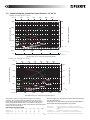
7.2 Capacity Diagram, Sound Data, Specifications - L4 XE EC
Supply air side (with F7 filter)
20
40
100
80
60
120
400
(''
300
.,
200
,'
Power consumption in Watt
Contact resistance (Pa)
l/s 0
(''
(''
100
),
/'
-'
+'
Pa 0
m3/h 0
/'
-'
70dB(A)
70dB
(A)
65dB(A)
65dB
(A)
+'
60dB(A)
60dB
(A)
,,[98
75dB(A)
75dB
(A)
W
0
100
200
300
400
500
$,
$(,
$*'
$,'
$.,
*'
+'
,,
-,
NXk\i9Xkk\ip
Pa
0
(,
=,=`ck\i
Air flow rate, m3 /h - Pressure correction factor
Extract air side (with F7 filter)
20
40
80
60
100
120
400
(''
300
.,
200
,'
(''
(''
/'
100
/'
-'
-'
),
-'[98
,,[98
,'[98
+'
+,[98
+'[98
+'
Pa 0
m3/h 0
100
Power consumption in Watt
Contact resistance (Pa)
l/s 0
0 W
300
200
400
500
Air flow rate, m3 /h - Pressure correction factor
Sound data is given at sound power level LwA in the capacity
diagrams and is corrected with the table below for the various
octave bands. Radiated noise produces Lw in the various octave
bands and total LwA. Radiated noise is estimated by finding the
noise level from the supply air table and deduct the total value found
in the correction factor table.
Correction factor for LwA
Hz
63
Supply air 9
Extract air-38
Radiated -47
125 250
6
-2
-33 -32
-42 -40
500
-3
-40
-43
1000
-4
-42
-44
2000 4000
-9
-17
-43
-44
-45 -49
8000
-31
-45
-57
LwA
-34,5
12
Data for supply air is measured in accordance with ISO 5136,
the “In duct method”.
Radiated noise is measured in accordance with ISO 9614-2.
Bruel & Kjær measuring equipment, type 2260.
Blue curves:
Green curves:
Air capacity at various capacity settings in Volt.
Supply air fan power consumption at various capacity
settings.
Red curves:
Sound power level LwA, cf. correction table.
Light blue correction axis:
Pressure increase using an EU-5 filter.
Light green correction axis: Pressure reduction using a water battery.
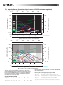
7.3 Capacity Diagram, Sound Data, Specifications - L7 XE (Transformer regulation)
Supply air side (with F7 filter)
40
160
120
80
200
500
250
400
200
230V
300
100
120V
105V
85V
60V
100
Pa
150
190V
170V
150V
200
85V
60V
0
Power consumption in Watt
Contact resistance (Pa)
l/s 0
m3/h 0
0
Pa
0
105V
230V
190V
170V
150V
120V
65dB(A) 70dB(A)
200
75dB(A)
20
80dB(A)
0
-15
-25
600
-40
800
-55
35
50
65
85
400
-5
50
W
Water Battery
F5-filter
Air flow rate, m3 /h - Pressure correction factor
Extract air side (with F7 filter)
40
200
160
120
80
500
250
400
200
230V
300
100
230V
120V
105V
85V
60V
100
Pa
150
190V
170V
150V
200
150V
60V
0
Power consumption in Watt
Contact resistance (Pa)
l/s 0
85V
105V
190V
170V
50
120V
50dB(A) 55dB(A)
m3/h 0
64dB(A)
200
60dB(A)
600
400
0
W
800
Pa
0
20
35
50
60
F5 Filter
3
Air flow rate, m /h - Pressure correction factor
Sound data is given at sound power level LwA in the capacity
diagrams and is corrected with the table below for the various
octave bands. Radiated noise produces Lw in the various octave
bands and total LwA. Radiated noise is estimated by finding the
noise level from the supply air table and deduct the total value
found in the correction factor table.
Correction factor for LwA
Hz
63
Supply air 3
Extract air 10
Radiated -55
125 250
1
2
8
5
-43 -35
500
-1
-2
-36
1000
-7
-11
-33
2000 4000
-11
-18
-19
-30
-31
-40
8000
-31
-48
-50
LwA
-27,1
13
Data for supply air is measured in accordance with ISO 5136,
the “In duct method”.
Radiated noise is measured in accordance with ISO 9614-2.
Bruel & Kjær measuring equipment, type 2260.
Blue curves:
Green curves:
Air capacity at various capacity settings in Volt.
Supply air fan power consumption at various capacity
settings.
Red curves:
Sound power level LwA, cf. correction table.
Light blue correction axis:
Pressure increase using an EU-5 filter.
Light green correction axis: Pressure reduction using a water battery.
7.4 Capacity Diagram, Sound Data, Specifications - L7 XE EC
Contact resistance (Pa)
l/s 0
40
160
120
80
200
500
250
400
200
300
150
200
(''
100
/'
100
(''
-'
+'
Pa
Power consumption in Watt
Supply air side (with F7 filter)
+'
0
m3/h 0
/'
-'
/*[98
.,[9
8 /'[98
.'[98
-'[98 -,[98
200
0
-5
0
20
50
-15
-25
600
-40
800
-55
35
50
65
85
400
0
W
Water Battery
Pa
F5-filter
Air flow rate, m3 /h - Pressure correction factor
Extract air side (with F7 filter)
40
80
160
120
200
500
250
400
200
300
150
200
100
(''
/'
100
(''
50
/'
-'
Pa
Power consumption in Watt
Contact resistance (Pa)
l/s 0
-'
+'
+'
0
m3/h 0
-,[98 -/[98
,'[98 ,,[98 -'[98
200
600
400
0
W
800
Air flow rate, m3 /h - Pressure correction factor
Sound data is given at sound power level LwA in the capacity
Data for supply air is measured in accordance with ISO 5136,
diagrams and is corrected with the table below for the various
the “In duct method”.
octave bands. Radiated noise produces Lw in the various octave
Radiated noise is measured in accordance with ISO 9614-2.
bands and total LwA. Radiated noise is estimated by finding the
Bruel & Kjær measuring equipment, type 2260.
noise level from the supply air table and deduct the total value
found in the correction factor table.
Blue curves:
Green curves:
Air capacity at various capacity settings in Volt.
Supply air fan power consumption at various capacity
settings.
Red curves:
Sound power level LwA, cf. correction table.
Light blue correction axis:
Pressure increase using an EU-5 filter.
Light green correction axis: Pressure reduction using a water battery.
Correction factor for LwA
Hz
63
Supply air 6
Extract air 11
Radiated -36
125
1
2
-31
250
-2
4
-33
500
-4
0
-41
1000
-5
-13
-42
2000 4000
-7
-14
-15
-28
-39
-41
8000
-27
-44
-47
LwA
-33,4
14
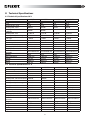
8 Technical Specifications
8.1 Technical Specifications L4 X
Rated voltage
Fuse
Rated current, total
L4 XE
230 V/50 Hz
10 A
8,7 A
L4 XE EC
230 V/50 Hz
10 A
8,0 A
L4 XW
230 V/50 Hz
10 A
5,7 A
L4 XW EC
230 V/50 Hz
10 A
5,0 A
Rated power, total
1990 W
1826 W
1315 W
1151 W
Rated power, electric
batteries
1650 W
1650 W
Rated power, fans
2 x 165 W
2 x 83 W
2 x 165 W
2 x 83 W
Rated power, preheating
975 W
975 W
975 W
975 W
Fan type
F-wheel
F-wheel
F-wheel
F-wheel
Fan motor control
Max. fan speed
Automatic control standard
Filter type (SUP/EXTR)
SUP filter dimensions (WxHxD)
EXTR filter dimensions
(WxHxD)
Weight
Duct connection
Height
Width
Depth
Transformer
2230 r/min
CS 50
F7/G3
225x220x50 mm
EC-Stepless
2900 r/min
CS 50
F7/G3
225x220x50 mm
Transformer
2230 r/min
CS 50
F7/G3
225x220x50 mm
EC-Stepless
2900 r/min
CS 50
F7/G3
225x220x50 mm
225x220x20 mm 225x220x20 mm 225x220x20 mm 225x220x20 mm
36 kg
Ø 160 mm
675 mm
1000 mm
350 mm
36 kg
Ø 160 mm
675 mm
1000 mm
350 mm
36 kg
Ø 160 mm
675 mm
1000 mm
350 mm
36 kg
Ø 160 mm
675 mm
1000 mm
350 mm
8.2 Technical Specifications L7 X
Rated voltage
Fuse
Rated current, total
L7 XE
230 V/50 Hz
16 A
10.7 A
L7 XE EC
230 V/50 Hz
16 A
10.2 A
L7 XW
230 V/50 Hz
10 A
6.4 A
L7 XW EC
230 V/50 Hz
16 A
5.9 A
Rated power, total
2470 W
2350 W
1470 W
1350 W
Rated power, electric batteries 2000 W
2000 W
Rated power, fans
2 x 230 W
2 x 170 W
2 x 230 W
2 x 170 W
Rated power, preheating
1000 W
1000 W
1000 W
1000 W
Fan type
F-wheel
F-wheel
F-wheel
F-wheel
Fan motor control
Max. fan speed
Automatic control standard
Filter type (SUP/EXTR)
SUP filter dimensions (WxHxD)
EXTR filter dimensions
(WxHxD)
Weight
Duct connection
Height
Width
Depth
Transformer
2120 r/min
CS 50
F7/G3
394x223x250 mm
EC-Stepless
2250 r/min
CS 50
F7/G3
394x223x250 mm
Transformer
2120 r/min
CS 50
F7/G3
394x223x250 mm
EC-Stepless
2250 r/min
CS 50
F7/G3
394x223x250 mm
394x223x20 mm
394x223x20 mm
394x223x20 mm
394x223x20 mm
66 kg
Ø 250 mm
680 mm
1170 mm
465 mm
66 kg
Ø 250 mm
680 mm
1170 mm
465 mm
66 kg
Ø 250 mm
680 mm
1170 mm
465 mm
66 kg
Ø 250 mm
680 mm
1170 mm
465 mm
15
9
Final Check
Control that:
• The duct insulation is in accordance with the manual and the technical documents
• Ducts are connected to the right nipples – check against the unit drawings below
• Temperature sencor installed in supply air duct, 0,5-1 meters from unit
• Drainage connected, sufficiently frost protected and functioning. Refer to separate guide in in water lock kit.
• Adjustment has been carried out in accordance with the manual and ventilation data documentation
• The unit operates normally at all stages
• Heating switches on
The installer may be held liable for any incorrect or defective installation.
Type L
Extract
Outdoor
Supply
Exhaust
Drainage
16
USER GUIDE
10 Important Safety Instructions
To reduce the risk of fire, electric shock or
injury, read all the safety instructions and
warning texts before using the unit.
This unit is only designed for ventilation air in
buildings.
It must not be used to extract combustible or
flammable gases.
Remove the power plug before commencing any
service and maintenance work.
Before you open the door, the unit must be dead and
the fans must have been given time to stop (min. 3
minutes).
The unit contains heating elements that must not be
touched when they are hot.
The unit must not be operated without the filters
being in place.
Follow the instructions in the user manual.
!
•
•
•
•
•
•
•
11.2
Frost Protection
The ventilation unit is provided with a special
thermoguard for maximum benefit of the heat
recovery section and maintenance of a balanced
ventilation. The thermoguard has a sencor stick
B6 with a double function. It is located in the heat
exchangers extract air duct and has a NTC-element
for controlling temperature and an indicator for
registration of moisture. This prevents frost in the
heat exchanger.
Selve frostsikringsfunksjonen har følgende forløp:
- Preheater EB2 is activated.
- When this does not provide sufficient frost
protection, the supply air fan, M1 ,speed is reduced.
To maintain a good indoor climate, comply
with regulations and, to avoid condensation damage, the unit must never be stopped
apart from during service/maintenance or in
connection with an accident.
11 Functional Decription
I kryssveksleren HR-X passerer den kalde uteluften
og den varme avtrekksluften i "kryss" uten å komme i
direkte kontakt med hverandre. Ved dette prinsippet vil
mye av varmen i avtrekksluften bli overført til tilluften.
I tillegg vil et termostatstyrt ettervarmeelement EB1
sørge for at tilluften holder ønsket temperatur. Denne
tilluften føres via kanaler og ventiler til oppholdsrom
og soverom. Avtrekksluften suges ut fra enten samme
rom eller via dørspalter/overstrømningsrister til toalett
og våtrom. Den brukte luften føres via kanalsystemet
tilbake til aggregatet, gir fra seg varme som nevnt, og
blåses ut av bygningen via takhatt eller veggrist.
11.1 Heating Elements
The heating elements are protected against
overheating by the F20/F21 overheating thermostats,
which switches off at 65 °C. As an additional safety
measure, the F10/F11 overheating thermostats switches
off at 80 °C. The overheating thermostats must be reset
manually (Chap. 6).
17
12 Cleaning - Maintenance L4 X/L7 X
Before opening the door of the heat recovery system: switch off the heat, let the fans continue for
three minutes to remove hot air, remove the power from the unit and wait 2 minutes before opening
the doors.
Doors: Opened by loosening both eccentric hooks and releasing the hooks. The doors can then be completely
removed.
Fans: Item nos. 9 and 10/Chap. 6. General Drawings. The fans normally require no maintanance. If the ventilation
unit is delivered combined with a kitchen hood (K-model), or is connected to an external kitchen hood
(A-model), the fans must be cleaned once pr. year. The fans are cleaned with a small brush and compressed
air, if available.
NB! Do not use water. Disassemble the fans as follows:
L4 X: Pull out the quick-release contacts. The fan with the visible quick-release contact is loosened by unscrewing
the 4 screws in the round motor plate and carefully pulling the motor out of the motor housing. For the fan
with the visible intake opening, the screw for the rail in the side wall must be removed and the rail pushed
down as far as possible. The entire fan housing can then be released and turned around. The fan can then be
released with 4 screws, like the first fan.
L7 X: The fan with the visible quick-release contact is loosened by unscrewing the 3 screws in the end of the fan
housing and carefully pulling the fan out. For the fan on which the screws are on the opposite side, the entire
fan housing must be loosened by unscrewing the mounting rails (2 screws) on each side of the fan, thus
releasing it. The fan can then be released with 3 screws, like the first fan. The fan can be disassembled most
easily if the exchanger cassette is removed first.
Filter: To preserve a healthy indoor environment, it is important to change filters when they are dirty. Dirty filters
lead to: Increased air resistance in the filter – less air in the home – the risk of bacterial growth in the filter
– in the worst case scenario, the system can be damaged.
How often the filters need to be changed depends on the degree of contamination of the air where they
are installed. In general, the filters need to be changed once a year, preferably in the autumn (after the
pollen season). In areas with a lot of dust and contamination, the filters should be changed in the spring
and autumn. Order no. for a complete set of filters: L4 X- 12318, L7 X - 12313
Loft model filter location
Thermoguard
Extract air filter:
Flat filter with cardboard frame
Supply air ilter:
Prefilter and
compact filter
Cross
exchanger
Exchanger
cassette:
Valves and
duct system:
Outdoor air
intake:
Roof hat:
Summer
operation:
Should be checked roughly once a year for dust and dirt in the air ducts. First remove the
thermoguard (3) and carefully pull the cross exchanger (11) out. If cleaning is required, place it in
a bowl with warm soapy water (NB! not soda) and finally flush it through with warm water. Clean
the thermoguard separately with a dry cloth. When removing/installing the exchanger cassette,
it is important to ensure that both the cassette and the sensor rod are located correctly and
that the cable plug is inserted in the contact. The thermoguard must be located 6 cm from the
top of the exchanger cassette and in the centre of the exchanger cassette. Located on the side
facing the extract air filter.
The valves should be cleaned at least once a year.
The duct system should be cleaned at least every 10 years.
Check once a year that the grille is not clogged with leaves, dust and dirt.
Check once a year that the drainage gap at the bottom is not clogged with leaves. This applies
only if the system has a roof hat.
During the warm part of the year (outside the heating season), there is no need to recover heat.
18
The exchanger cassette can be replaced with a summer cassette that is available as an accessory.
This is pushed into place where the cross exchanger (11) is located. This allows the outdoor air to
enter the building directly without heat recovery taking place. The thermoguard (3) must then be
transferred to the summer cassette. Its location is shown on the label. NB! At the same time, the
heating must be switched off (press the left switch (+) on the control panel so that the green light
goes out) to avoid the heating element switching on unnecessarily.
Remember to reverse this again in the autumn.
Drainage:
!
At the base of the unit there is a condensation water drain (14) that conducts condensation water
to the waste water drain. It is important that this drain is always open, in good condition and well
insulated where it is exposed to frost. It is also recommended that you keep an eye on the drainage
system to avoid any leaks occurring.
Lack of cleaning as prescribed will increase the risk of fire in the event of an accident.
19
COMMON
13 Fault Location
If a power failure occurs the ventilation unit will return to the factory settings when restarting.
Error:
The fans do not function and/
or:
Do the following:
The fans are not running
or unable to regulate
- Check that the power cord is correctly inserted in the outlet
- Check that the fuses in the fuse box are active
- The overheating thermostat(s) (Pos.no. 7, 8/Chapt. 6) General
Drawings) may have been activated. Remove white
plastic cover and push white reset button.
- Check that thermoguard (Pos. no. 3) is connected.
Suppy air feels too cold
- Check that the heating battery switch is on and that the summer
cassette is not installed.
- The heating regulation thermostat (Pos.no. 4/Chapt. 6) may be set to
higher temperature.
- Check thet the thermoguard termofuktføler (Pos. no. 3) is connected.
- The overheating thermostat (s) (Pos.no. 7, 8) may have been
activated. Remove white cover and press the white reset button.
Check that the switch for for secondary heating is activated
The air supply substantially reduced
- Filter (Pos.no. 1, 2/Chapt. 6) may be clogged with dirt. Clean or
replace, see under Cleaning - Maintenance.
- Grille for supply air inlet may be clogged, see
under Cleaning - Maintenance.
If non of these measures solves the trouble, contact your supplier for service.
Please report the model type and serial number (found on the sign inside the ventilation unit/
open door).
20
14 CE Declaration of Conformity
This declaration confirms that the products meet the requirements in the following Council Directives and standards:
89/336/EEC Electromagnetic compatibility (EMC)
73/23/EEC Low-voltage Directive (LVD)
NEK EN 60335-1 :94 + A11:95 + A1:96 + A1:96 + A12:96
55014:93, EN 61000-3-2/-3:95, EN 55014-2:97
Manufacturer:
Equipment group:
FLEXIT AS, Televeien 15, N-1870 Ørje
Ventilation units for installation in ducts
Type:
VG 400: 1997
VG 700: 1997
The product is CE-marked:
Shown in the list above
FLEXIT AS 02/05/2001
Pål J. Martinsen
General Manager
The right to give notice of lack of conformity applies to this product in accordance with the existing terms of sale,
provided that the product is correctly used and maintained. Filters are consumables.
The symbol on the product or on its packaging indicates that this product may not be treated as household waste. Instead it shall be handed over
to the applicable collection point for the recycling of electrical and electronic equipment.
By ensuring this product is disposed of correctly, you will help prevent potential negative consequences for the environment and human healthe,
which could otherwisw be caused by inappropriate waste handeling of this product. For more detailed information, please contact your local city
office, your household waste disposal service or the shop where you purchased the product.
Notice of lack of conformity as a result of incorrect or defective installation must be submitted to the installation company responsible.
The right to give notice of lack of conformity may lapse if the system is used incorrectly or maintenance is grossly neglected.
21
15 Product/Environmental Declaration
The declaration applies to the Flexit L4 X/L7 X ventilation units
Materials:
Materials with which the user or treated air come into contact:
• The unit’s outer walls are made of galvanised steel DX51D+Z275 (NS-EN 10142)
• The rotary wheel-type heat exchanger, made of aluminium
• Miscellaneous electric cables with PVC insulation
• Electric motors consisting of galvanised steel, aluminium and copper
• Heating elements made of steel
• Air filters of glass fibre, cardboard and EVA melting glue
Materials in the unit with which service personnel may come into contact:
• Plastic-insulated electric cables
• Miscellaneous other electrical components
• Insulation of type EPS/Dacron
Other materials that may occur in small quantities:
• Silicon sealant
• Polyethylene foamed plastic
• EPDM rubber gaskets
• Miscellaneous steel screws, nuts and pop rivets, plus small quantities of copper and brass.
Safety:
Materials:
Use:
The materials are considered to be completely harmless to users.
The unit is an electrical appliance which must be made dead for service and inspection. The unit also
contains rotating motors that must have time to stop before the inspection door is opened, plus heating
elements with a high operating temperature.
22
23
Flexit AS, Televeien 15, N-1870 Ørje
www.flexit.com