1
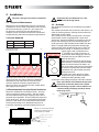
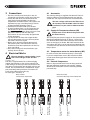
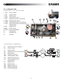
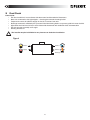
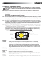
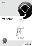
Connections
4.1 Automatics
The control package is supplied with the unit. The lowvoltage cable must be laid between the unit and the
switch unit. See separate automatics documentation.
• The ducts usually come from joists and are
connected to the nipples on the top of the unit.
• Ensure that the ducts are connected to the
right nipple. See the labelling on the unit
(top/bottom and behind door). The symbols are
explained on page 3 and the placing is shown
on measurement drawing in Chap. 1.
• Pull the duct insulation well up to the unit.
• To avoid condensation, it is very important for
the outdoor air duct to have insulation and a
plastic sleeve pulled right down to the unit. Seal
the plastic sleeve to the unit with tape.
The outdoor air duct is normally designed with
25 mm insulation.
• Lay the outdoor air duct with a slight incline
towards the outdoor air cap so that any water
that enters drains out again.
• With a short distance between the unit and
the exhaust point, sound insulation must be
installed to meet the requirements for the outdoor sound level.
• Ducts must have good sound insulation, particularly above the unit.
4.2 Supply Air Temperature Sencor (B1)
Temperature sensor B1 must be placed after
the water battery.
This should be placed in the supply air duct (red on Flexit
Drawing/Symbold Used page 3) approx. 1 m from the
unit. Roll out the marked wire coil on the unit located
close to the supply air intake. Drill a Ø 7 mm hole in the
duct where the sencor can be placed. Seal the hole with
a sealant and tape the wire on the outside of the duct to
keep in place.
4.3 Temperature sensor for water battery (B5)
Electrical Works
In order to avoid that the water battery is destroyed
by frost a temperature sensor (B5) must be installed
on the return water pipe where the cold water leaves
the battery
The unit should be equipped with a separate earth-leakage circuit-breaker.
Power Cord
4.4 External Components
The unit is supplied with a 1.8 m cable and plug
(which also functions as the service switch). The
cable emerges on the top of the unit (front) on the
left side of a right model and the right side of a left
model. This is connected to a 230 V 50 Hz singlephase earthed power point that is located in an
easily accessible position close by.
For fuse types, see chap. 8.
Refer to separate electrical circut drawing enclosed
with the individual ventilation unit and Fig. 4 below.
All electrical connections must be made by qualified
personell only.
Water models
Connected to external box
Electrical models
Connected directely on the mainvboard
6
Damper motor 230V
2-wires
Vent motor 230V
3-way vent
Pump motor 230V
Damper motor 230V
2-wires
Damper motor 230V
3-wires
Fig. 4
Damper motor 230V
3-wires
4
The low-voltage cable must be laid at least
30 cm away from the 230 V cable. For flush
installation, lay the cable in 20 mm conduit
pipe.
B5 Temperature
sensor Water battery
3