1
SIDSA
Semiconductor Design Solutions
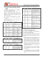
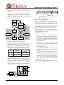
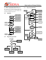
(see figure 2.1). After the stop condition, the bus is
considered to be free, and a high level must be set
in both SDA and SCL lines.
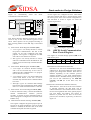
VDD
SCL (serial clock)
SDA (serial data)
SCL in
SCL in
SCL out SDA in
SCL outSDA in
SDA out
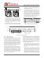
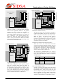
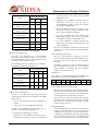
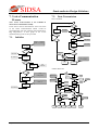
• Acknowledgement: All address and data words are
serially transmitted through the SDA line in 8-bit
words, most significant bit first. Each byte
transmitted is followed by an acknowledge bit set
by the receiver. The receiver must pull-down the
SDA line during the 9th clock cycle to acknowledge
that it has received each word. During this cycle,
the transmitter has to release the SDA line to
receive the confirmation from the receiver.
SDA out
Fig. 2.2: Connection of devices to the 2-wire bus
bus free
• Start Condition: A high-to-low transition in SDA
line with SCL high is a start condition (see figure
2.1). Only the master device may generate this
situation. The bus is considered to be busy after a
start condition. A start command always precedes
any command in the bus.
bus busy
SCL out by
transmitter
1
2
8
9
SDA out by
transmitter
not acknowledge
SDA out by
receiver
• Stop Condition: A low-to-high transition in SDA
while SCL is high is interpreted as a stop condition
acknowledge
start condition
clock pulse for acknowledge
Fig. 2.3: Acknowledge of receiver on the 2-wire bus
Bus busy
start condition
SCL
address word
1
1st data word
2
8
9
....... last data word
1
8
stop condition
9
read
SDA
MSB
write
address field
operation field
acknowledge cycles
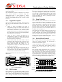
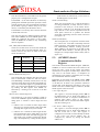
Fig. 2.4: Data transfer on the 2-wire interface
2.2.
Data Transfer
After a start condition, the master device must send a
slave address. This first word has two purposes: firstly,
it is used to identify the slave device in the bus;
secondly, it is used to establish the transfer direction of
the communication (that is, configure the slave device
as receiver or transmitter). The first word is seven bits
long (address field) followed by an eight bit (operation
field) which is the R/W command select bit. A read
operation is initiated if this bit is high; otherwise, a
write operation is initiated (see figure 2.4).
The slave addressed must pull-down the ninth bit as
mentioned before (see figure 2.3). If the master device
do not detect a zero in the ninth clock cycle, no device
has been addressed. The master must then re-try to start
a communication or release the 2-wire bus. The first
action would be done by sending a different address
after a new start condition. The second one will be
done by producing a stop condition.
Chapter 8. Serial Communication Interface
The number of bytes that can be transmitted between
the start and the stop condition is unrestricted. Data
transfer is always finished by an stop command (see
figure 2.4). In other words, several start commands are
allowed without releasing the bus. Various
combinations of read/write format are possible in the
same transmission session. These formats are described
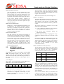
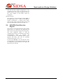
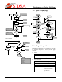
below (and shown in figure 2.5):
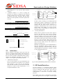
• Master transmitter: The master device transmits
data to the slave receiver. The transfer direction is
not changed, and the acknowledge bit is always set
by the slave. This format is used in write
operations.
• Master receiver: The master device reads data
from the slave after the first byte transmitted. The
transfer direction changes after the first byte (that
is, the address word transmission has master→ slave
direction while any other word is slave→ master
transmitted). The acknowledge bit is always set by
the receiver. Due to this fact only the first
3