1
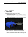
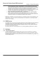
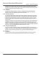
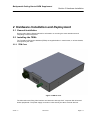
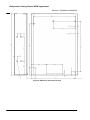
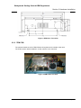
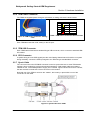
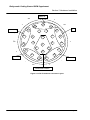
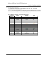
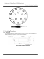
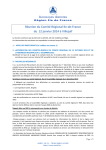
Bathyswath Getting Started OEM Supplement Bathyswath Email: [email protected], Web: www.bathyswath.com Issue 1.1 Dec 2013 Bathyswath . This is an unpublished work, the copyright in which vests in Bathyswath. All rights reserved. The information contained herein is the property of Bathyswath and is supplied without liability for errors or omissions. No part may be reproduced or used except as authorized by contract or other written permission. The copyright and the foregoing restriction on reproduction and use extend to all media in which this information may be embodied. Bathyswath Getting Started OEM Supplement Contents This Page Intentionally Left Blank Issue 1.1 Dec 2013 Page ii Bathyswath Getting Started OEM Supplement Contents Contents Contents iii Preface v 1 General Description 1.1 System Description 1.2 OEM Version 1.3 Hardware 1.4 Software 2 Hardware Installation and Deployment 2.1 General Installation 2.2 Installing the TEMs 2.3 Installing Transducers 3 Reference 3.1 Glossary 3.2 Bathyswath Web Page 3.3 Bathyswath Support Issue 1.1 Dec 2013 1-1 1-1 1-2 1-2 1-4 2-1 2-1 2-1 2-10 3-1 3-1 3-4 3-4 Page iii Bathyswath Getting Started OEM Supplement Preface Preface This document provides additional information to the main Bathyswath Getting Started manual, for use with the OEM version of the product. Refer to the main Getting Started document for information on how to set up the system and its software. This document gives information on the interfaces that are not exposed in the standard version of Bathyswath. This manual refers to Bathyswath V1 OEM. . Issue 1.1 Dec 2013 Page v Bathyswath Getting Started OEM Supplement Contents This Page Intentionally Left Blank Issue 1.1 Dec 2013 Page vi Bathyswath Getting Started OEM Supplement Section 1 General Description 1 General Description 1.1 System Description Bathyswath is a wide-swath bathymetry and sidescan imaging system. The standard basic sonar system consists of the following components: Transducer Interface Unit (TIU). This contains the main system electronics, and connects the sonar transducers to a PC computer Sonar transducers: one facing port, and one facing starboard. In the base system, the user mounts the transducers to a suitable location on their vessel. Additional mounting hardware is optionally available: see below. Bathyswath software suite, for installation on the Customer’s PC computer. The Bathyswath software supports real-time data acquisition, post-processing, and interfaces to most third-party software suites. Figure 1-1 The Bathyswath base system comprises a Transducer Interface Unit (left shows one type- others are available) and two sonar transducers (Bathyswath-H shown right). Further optional components include: Issue 1.1 Transducer mounting bracket: a ‘V’ bracket, which holds the two transducers at the correct mounting angles. For dedicated use on a small vessel or platform, the user may prefer to Dec 2013 Page 1-1 Bathyswath Getting Started OEM Supplement Section 1 General Description mount the transducers directly onto the platform. The two transducers should be fixed facing downwards at an angle of approximately 30° from the horizontal, with one facing port and the other starboard. In this case, the transducer mounting bracket is not required. Transducer drawings and further advice are available from Bathyswath on request. Transducer pole: this allows the mounting bracket to be mounted over the side of a vessel, or similar. It is provided in four easily separated sections, for easy transport. Bow-mounting kit: fixes the transducer pole to the bow of a vessel; includes an anglebracket, which holds the transducers level on a sloping bow. Laptop computer, configured for use with Bathyswath. This can be used for preparing survey session plans, and for post-processing collected data. It is provided complete with an Ethernet-to-serial unit, for interfacing to auxiliary sensor systems. Bathyswath is available in three sonar frequencies. The 468 kHz version is most applicable to very small platforms, due to the small size and light weight of the transducers, and the higher spatial resolution of the imaging. 1.2 OEM Version In the OEM version, only the main “transducer electronics modules” (TEMs) and sonar transducers are supplied, together with the Bathyswath software. The user is expected to install these components in their own system, for example underwater vehicles, or sonar systems integrated into custom-built equipment cabinets. The system options for mounting transducers, etc. are also available to OEM clients on request. 1.3 Hardware 1.3.1 General description The main components of a standard Bathyswath system are sonar transducer(s), Transducer Electronics Module(s) (TEMs) in a Transducer Interface Unit (TIU), and a PC computer. Data is recorded by the PC computer onto disk. Data may be archived onto standard PC e.g. stored on an external (USB) disk drive. Issue 1.1 Dec 2013 Page 1-2 Bathyswath Getting Started OEM Supplement Section 1 General Description PC Computer Auxiliary Sensors Position Motion Sensor Compass Electronics Transducer Electronics Modules (TEMs) in Transducer Interface Unit (TIU) Interface the sonar transducers to the PC, and - Produce transmit signal - Amplify received signal - Digitise signal and transmit it to PC Sonar Transducers Piezo-electric elements, arranged in horizontal rows. No active electronic components. Encased in nylon or polyurethane Figure 1-2 Bathyswath Hardware Block Diagram In the OEM version, only the TEMs and transducers are supplied, and users install the TEMs in their own electronics housings. 1.3.2 Transducer Electronics Modules (TEMs) The Transducer Electronics Modules connect the sonar transducers to the PC computer. One Transducer Electronics Module is used for each sonar transducer. Each Transducer Electronics Module (TEM) contains a single printed circuit board (PCB), with flexible connections to the computer and sonar transducer. It is thus extremely robust. The TEM on-board data processing is implemented in a large FPGA. The TEM PCB has sub-sections performing the following functions: Transmitter, which sends an electrical pulse to the sonar transducers. This makes the sonar pulse. Analogue Receiver, which amplifies the returned echo signals, and produces sidescan amplitude data. The Bathyswath analogue circuits provide very high gain and low noise, enabling signals below acoustic sea noise to be measured. The limiting factor to performance is therefore determined only by the external environment. Phase Interface, which receives the amplified sonar signals, measures the phase differences between them and converts the sidescan data into digital form. 1.3.3 USB system interface Each Transducer Electronics Module (TEM) is connected to the PC computer using an industrystandard USB connection. Up to 4 TEMs can be connected to one PC, although two or three are the usual number. If the sonar system needs to be mounted at a distance from the computer, then the USB interface can be extended using a commercial USB extender or USB-to-Ethernet converter. Alternatively, a remote compact computer unit can be installed close to the sonar system and auxiliary sensors, Issue 1.1 Dec 2013 Page 1-3 Bathyswath Getting Started OEM Supplement Section 1 General Description which then acts as a data storage and control unit for the sonar. This remote unit can then be operated over a network link, either cable or Wireless, using standard remote interface software. This latter option is useful for remote systems, such as USVs (unmanned surface vehicles), UUVs (unmanned underwater vehicles) and towed vehicles. 1.3.4 Software The Bathyswath software operates in Windows 7, Vista, XP and 2000. Commands may be entered via the mouse and keyboard. A wide range of displays is available, which allow the operator to monitor and control the operation of the sonar system. 1.3.5 Auxiliary interfaces The operating software supports ports to allow real time interfaces to other survey suite sensors, including Motion Measurement, Position (DGPS / RTK DGPS) and Heading (NMEA 0183 format). It also supports multiple information streams from integrated systems such as the CodaOctopus F180. Tide height information can be input manually either from a telemetry system or in post processing. Water speed of sound profiles may be input manually after speed of sound dips or in post processing. Interfaces are supported using RS232 serial ports and Ethernet UDP ports. Not all attitude sensors provide Ethernet interfaces, but where they do, they are preferable because they are faster, and therefore the delay between sending and receiving is shorter, and because they contain more information. For example, such interfaces generally attach the time at which the data was valid with the string. This allows the Bathyswath user to opt to use the sensor time for processing, rather than the PC time. See section Error! Reference source not found. for details. 1.3.6 Personal Computer (PC) The PC serves as the man-machine interface. Commands may be entered via the mouse and keyboard. A wide range of displays is available, which allow the operator to control and monitor the operation of the sonar system. In OEM systems, this computer could be a single-board computer. At present, only Windows operating systems are supported by the Bathyswath software. 1.4 Software The system software works the same way with Bathyswath OEM as it does with the standard product. Refer to the main Getting Started manual and the Online Help for more details. Issue 1.1 Dec 2013 Page 1-4 Bathyswath Getting Started OEM Supplement Section 2 Hardware Installation 2 Hardware Installation and Deployment 2.1 General Installation See the main Getting Started manual for information on mounting the sonar transducers and integrating to external systems. 2.2 Installing the TEMs The Transducer Electronics Modules (TEMs) are supplied either in metal cases, or as bare boards, as required by the client. 2.2.1 TEM Case Figure 3 TEM in Case The dimensions and fixing hole locations are identical to old-style 5.25” computer disk drives and similar peripherals. The power supply connection is also exactly the same as those devices. Issue 1.1 Dec 2013 Page 2-1 Bathyswath Getting Started OEM Supplement Section 2 Hardware Installation Figure 4 TEM Case: Side and Top View Issue 1.1 Dec 2013 Page 2-2 Bathyswath Getting Started OEM Supplement Section 2 Hardware Installation Figure 5 TEM Case: Front View 2.2.2 TEM PCB The external interfaces of the TEM PCB are all exposed to the outside of the case. The PCB is shown below installed in a case, with the cover removed. Figure 6 TEM PCB, Front View Issue 1.1 Dec 2013 Page 2-3 Bathyswath Getting Started OEM Supplement Section 2 Hardware Installation Figure 8 TEM PCB, Digital & Power Sections Figure 7 TEM PCB, Analogue Section 2.2.3 Mounting the PCB The TEM PCB has five mounting holes, which take M3 screws. See below, and Figure 4, top view, for the locations of these holes. Figure 9 TEM PCB Mounting Issue 1.1 Dec 2013 Page 2-4 Bathyswath Getting Started OEM Supplement Section 2 Hardware Installation 2.2.4 TEM Power Connector The TEMs are supplied power through a 4-pin Molex; a mating connector is shown below. Pin # Figure 10 TEM Power Connector - Mating Lead Colour Function 1 Yellow +12 V 2 Black Ground 3 Black Ground 4 Red +5 V Table 1 TEM Power Connector Power Pin-Out Each TEM takes less than 10W, mostly on the 5V input. 2.2.5 TEM USB Connector Each TEM board is fitted with a standard B-type USB connector, which connects to standard USB A-B cables. 2.2.6 PPS Connector If system timing is to use PPS signals (see the main Getting Started manual for advice on system timing methods), connect the PPS input signal to the TEM using a standard BNC connector. 2.2.7 Synch Cable The connector next to the PPS BNC connector is used to synchronise two or three TEM boards together; this is needed for synchronous transmit operations. Bathyswath cable part 01320 is needed for this; contact Bathyswath to supply one if needed. Figure 6 shows the revision 2 board; the later revision 5 boards use a Lemo connector in this location. Note that one of the TEMs is set to be the “master”; this is set by a special link in one of the connectors on the cable. Figure 11 Synch Cable for 2 TEMs Issue 1.1 Dec 2013 Page 2-5 Bathyswath Getting Started OEM Supplement Section 2 Hardware Installation Figure 12 Sync Cable for 3 TEMs 2.2.8 Auxiliary Connector The connector to the right of the Synch connector is used for special purposes, and is not normally connected in most systems. 2.2.9 TEM Transducer Connector A Bathyswath transducer is connected to each TEM using the transducer connector. By default, the software assigns port 1 to the lowest-numbered serial number transducer (the software reads the serial number through the USB port), port 2 to the next, and so on. Port 1 is assigned as the port transducer and port 2 as the starboard transducer. Issue 1.1 Dec 2013 Page 2-6 Bathyswath Getting Started OEM Supplement Section 2 Hardware Installation The wiring of the Bathyswath transducer connectors in the standard TEM is shown in Figure 2-13. TIU: Pin letter on 26way Connector Function Description B + Stave A A - Stave A R SCREEN Stave A P + Stave B N - Stave B M SCREEN Stave B L + Stave C K - Stave C J SCREEN Stave C H + Stave D G - Stave D F SCREEN Stave D E + TX D - TX C SCREEN TX The different transducer frequency versions are encoded in pins W, X, Y, c and b. These codes are implemented in the transducer connectors as follows: Issue 1.1 Transducer Implementation 117 Pins W Y and b linked together 234 Pins X c and b linked together 468 Pins c and b linked together Dec 2013 Page 2-7 Bathyswath Getting Started OEM Supplement Section 2 Hardware Installation Stave A - Sc + A + R Stave B Sc B P T X C T S - a N Sc U b Z M V c E + W Y F L + D X G K Stave C J H Stave D - Sc + Transducer Select Lines Figure 2-13 TIU Transducer Connector Layout Issue 1.1 Dec 2013 Page 2-8 Bathyswath Getting Started OEM Supplement Section 2 Hardware Installation 2.2.10 Transducer Connector The standard Bathyswath transducers are supplied with short cable “tails”, fitted with an underwater connector as described below. The AUV version of the transducers are not fitted with connectors, because different vehicles need different termination arrangements. Instead, they are supplied with bare-ended cable tails, with the function of each wire described on labels attached to each cable core. On the transducer 1-metre tail, the connections are as follows: Issue 1.1 Pin number on 16-way con Function Description Colour 15 + Stave A White 14 - Stave A Blue 4 SCREEN Stave A N/A 13 + Stave B White 12 - Stave B Orange 3 SCREEN Stave B N/A 10 + Stave C White 9 - Stave C Yellow 2 SCREEN Stave C N/A 8 + Stave D White 7 - Stave D Green 1 SCREEN Stave D N/A 6 + TX White 16 - TX Red 5 SCREEN TX N/A 11 Overall Screen Overall Screen N/A Dec 2013 Page 2-9 Bathyswath Getting Started OEM Supplement Section 2 Hardware Installation 6 +ve -v e 16 7 Transmit -ve +ve Stave 15 5 Screen Stave A Stave D 3 2 -ve +ve 13 Screen Screen 9 -ve Screen Scree n 8 14 4 1 +ve StaveC Stave B 12 -ve +ve 10 11 View 2.3 Installing Transducers 2.3.1 Mounting The mounting details for the standard transducers are given in the main Getting Started manual. OEM systems may be supplied on request with AUV transducers. Figure 14 AUV Transducer Dimensions Issue 1.1 Dec 2013 Page 2-10 Bathyswath Getting Started OEM Supplement Section 3 Reference 3 Reference 3.1 Glossary Issue 1.1 PPS A system of electronic pulses for synchronising subsystem clocks 3D Three-dimensional AGDS Acoustic Ground Discrimination System: a system that uses data from an echosounder to determine the type of the seabed ASCII A common computer format for human-readable text data Attitude The angular orientation of the system AUV Autonomous underwater vehicle Bathymetry Measuring depth Bathyswath-H High-frequency Bathyswath variant, working at 468kHz Bathyswath-L Low-frequency Bathyswath variant, working at 117kHz Bathyswath-M Medium-frequency Bathyswath variant, working at 234kHz Beam-former A sonar system that generates discrete beams of angular measurement to the seabed. Synonymous with ‘multibeam’. CAD Computer-aided design: computer software drawing packages CD Compact disk Chart datum A nationally or internationally agreed baseline for height measurement COTS Commercial-off-the-shelf: i.e., bought from a shop, rather than specially built for a one-off job DC Direct current DGPS Differential GPS: improves the accuracy of basic GPS by comparing the position obtained by a GPS system with that obtained at a fixed GPS station at a known location DTM Digital Terrain Model: a digital ‘map’ of the seabed, where depth and sidescan data are stored with reference to their geographical position DVD Digital versatile disk EMC Electromagnetic compatibility: robustness to external electrical ‘noise’ signals, and limiting transmission of such unwanted signals Ethernet A commonly used method for connecting computers together in local networks FPGA Field Programmable Gate Array: a digital electronic logic chip that can be programmed to carry out a set of tasks GMT Greenwich Mean Time; time zone; the Bathyswath software works in GMT GPS Global Positioning System: the most commonly-used satellite positioning system Grazing angle The angle that a sound ‘beam’ makes with the seabed Dec 2013 Page 3-1 Bathyswath Getting Started OEM Supplement Section 3 Reference Issue 1.1 Grid file The file used by the Grid Processor application to store its data. Uses an ‘.sxg’ file extension. Gridproc The Grid Processor application Horizontal range The maximum reach of the sonar, measured horizontally along the seabed; compare with ‘Slant range’ Hydrography Measurement of physical characteristics of waters; commonly used to refer to those measurements and descriptions of navigable waters necessary for safe navigation of vessels Interferometer A sonar system that measures depths by comparing the phase of the signal received on a set of vertically-separated transducer staves. Also called ‘Phase Differencing Bathymetric System’ (PDBS) Inverter A unit that provides mains (120 or 240V AC) power supply from a DC supply, usually from a battery Line spacing The distance between survey lines run across the seabed LVC Line Voltage Conditioner: a unit that ‘cleans’ a power supply, to reduce the effects of ‘noise’ or possibly damaging ‘spikes’ in the supply Multibeam See ‘Beam-former’ NMEA National Marine Electronics Association; the NMEA 0183 format is commonly used to send data from marine electronics equipment such as compasses and positioning systems Noise Unwanted signal NTP Network Time Protocol: a method for synchronising computer clocks over a network Online help The electronic user manual that is accessed directly from the Swath software Patch test A method used to calibrate the relative locations and angles of the components of a survey system, by comparing depth results from overlapping survey runs PC Personal Computer PC Clock Recording the time of a data sample using the time of the computer’s clock at the instant the sample is received in the software. Compare with ‘Sensor Clock’ PDBS Phase Differencing Bathymetric System; see ‘Interferometer’ Ping A complete transmit-receive cycle, measuring depth and sidescan information over a profile of the seabed. Also sometimes used to refer to just the transmitted acoustic signal. Postprocessing Processing sonar data after it has been collected; compare with ‘real time’ PRF Ping (or pulse) repetition frequency: the number of pings emitted per second Profile A 2D set of depth measurements, usually taken sideways from a survey vessel PSU Power Supply Unit QA Quality assessment Dec 2013 Page 3-2 Bathyswath Getting Started OEM Supplement Section 3 Reference Issue 1.1 Raw data file The file used by the Swath Processor application to store raw data. Uses an ‘.sxr’ file extension. Real time Data processing at the same time as data is collected; compare with ‘Post-processing’ RF Radio frequency RIB Rigid inflatable boat ROV Remotely-operated vehicle; an unmanned underwater vehicle that is connected to a surface vessel by a cable and controlled by a human operator RS232 A commonly-used format for serial data connections RTK Real-time kinematic GPS: an accurate form of GPS measurement Sensor Clock Recording the time of a data sample using a clock maintained inside the sensor itself. Compare with ‘PC Clock’ Session file The file used by the Swath Processor application to store its settings. Uses a ‘.sxs’ file extension. Sidescan Images of the seabed using the amplitude (strength) of the acoustic returns from the seabed. These are usually represented as grey pixels in a ‘waterfall’ display on the screen, with the brightness of pixels representing the strength of the signal. Slant range The maximum reach of the sonar, measured in a direct line from the sonar transducers to the seabed; compare with ‘Horizontal range’ Spreading loss Reduction of the amplitude of the sonar signal as it passes through the water Squat Change in height of a vessel in the water as the vessel moves Survey line An area of the seabed is usually surveyed by running a series of parallel straight lines across it Swath The Swath Processor application swath A ‘ribbon’ of seabed depth measurements, made up of a series of ‘profile’ measurements of depth as the sonar is moved forwards over the seabed SWATHplus Previous versions of the Bathyswath sonar were called “SWATHplus” Swathsounding Measuring the depth in a line extending outwards from the sonar transducer, then moving forwards to build up swaths TCP/IP A data format used to transfer data over Ethernet. UDP is another type. TCP/IP is a more reliable protocol, but is slightly slower. TEM Transducer Electronics Module: provides the input and output electronics for one sonar transducer Third-party software Software that is produced by organisations other than Bathyswath or its clients TIU Transducer Interface Unit: the blue box containg the TEMs Transducer The component that is placed in the water and converts sound energy into electrical signals and vice versa TVG Time-varying gain: an adaptable gain correction applied to sidescan data to remove the gross changes in amplitude caused by range and transducer beam shape, leaving an image of the seabed itself Dec 2013 Page 3-3 Bathyswath Getting Started OEM Supplement Section 3 Reference UDP User Datagram Protocol; see ‘TCP/IP’ UPS Uninterruptible Power Supply: a power supply that maintains a mains power supply from battery if the mains supply (e.g. from a generator) fails USB Universal Serial Bus. A common computer peripheral interface. USV Unmanned surface vehicle UTC Coordinated Universal Time; a time zone, equivalent to GMT UTM Universal Transverse Mercator: a commonly-used format for representing latitude and longitude positions in a plane representation as Easting and Northing UUV Unmanned underwater vehicle; usually synonymous with AUV V-bracket The V-shaped mechanical assembly that holds a pair of transducers XTF An industry-standard data format, commonly used for sidescan data. These files use a ‘.xtf’ file extension. xyz A position in three-dimensional space xyza Three dimensional position plus amplitude ZDA An NMEA 0813 protocol message that is used with PPS signals to synchronise subsystem clocks 3.2 Bathyswath Web Page Latest information on Bathyswath and related products can be found on the Bathyswath web page: www.bathyswath.com 3.3 Bathyswath Support Technical support is available from Bathyswath. Time-limited support may be provided with the sale, after which yearly support packages can be purchased. A convenient route to support is to email [email protected] Issue 1.1 Dec 2013 Page 3-4