1
ASE® 300 ACCELERATED SOLVENT EXTRACTOR
OPERATOR’S MANUAL
© 2000 Dionex Corporation
Document No. 031672
Revision 01
April 2000
©2000 by Dionex Corporation
All rights reserved worldwide.
Printed in the United States of America.
This publication is protected by federal copyright law. No part of this publication
may be copied or distributed, transmitted, transcribed, stored in a retrieval system,
or transmitted into any human or computer language, in any form or by any means,
electronic, mechanical, magnetic, manual, or otherwise, or disclosed to third parties
without the express written permission of Dionex Corporation, 1228 Titan Way,
Sunnyvale, California 94088-3603 U.S.A.
DISCLAIMER OF WARRANTY AND LIMITED WARRANTY
THIS PUBLICATION IS PROVIDED “AS IS” WITHOUT WARRANTY OF
ANY KIND. DIONEX CORPORATION DOES NOT WARRANT,
GUARANTEE, OR MAKE ANY EXPRESS OR IMPLIED
REPRESENTATIONS REGARDING THE USE, OR THE RESULTS OF THE
USE, OF THIS PUBLICATION IN TERMS OF CORRECTNESS,
ACCURACY, RELIABILITY, CURRENTNESS, OR OTHERWISE.
FURTHER, DIONEX CORPORATION RESERVES THE RIGHT TO REVISE
THIS PUBLICATION AND TO MAKE CHANGES FROM TIME TO TIME
IN THE CONTENT HEREINOF WITHOUT OBLIGATION OF DIONEX
CORPORATION TO NOTIFY ANY PERSON OR ORGANIZATION OF
SUCH REVISION OR CHANGES.
TRADEMARKS
AutoASE , AutoSeal , and DX-LAN are trademarks of Dionex Corporation.
ASE® 200 is a registered trademark of Dionex Corporation.
Teflon®, Tefzel®, and Viton® are registered trademarks of E.I. duPont de Nemours
& Company.
PRINTING HISTORY
Revision 01, April 2000
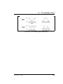
Contents
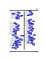
1 • Introduction
1.1
ASE 300 Options . . . . . . . . . . . . . . . . .
1-2
1.2
About This Manual . . . . . . . . . . . . . . . .
1.2.1 Typefaces . . . . . . . . . . . . . . . . .
1.2.2 Safety Messages and Notes . . . . . . .
1-3
1-3
1-4
1.2.3
1-5
Symbols . . . . . . . . . . . . . . . . . .
2 • Description
2.1
. . . .
. . . .
. . . .
2-1
2-3
2-5
. . . .
2-7
. . . .
. . . .
. . . .
2-8
2-9
2-10
2.2
Extraction Process . . . . . . . . . . . . . . . . .
2-11
2.3
Operating Modes . . . . . . . . . . . . . . . . .
2.3.1 Local Mode . . . . . . . . . . . . . . . .
2.3.2 Remote Mode . . . . . . . . . . . . . . .
2-22
2-22
2-22
2.4
Method and Schedule Control . . . . . . . . . .
2-23
Doc. 031672-01 4/2000
Operating Features . . . . . . . . . . . . .
2.1.1 Control Panel Display . . . . . .
2.1.2 Control Panel Keypad . . . . . .
2.1.3 Sample Cells, Rinse Tubes, and
Cell Tray . . . . . . . . . . . . .
2.1.4 Collection Bottles, Rinse Bottles,
and Bottle Tray . . . . . . . . . .
2.1.5 Solvent Reservoir Compartment
2.1.6 Electronics Area . . . . . . . . .
i
Contents
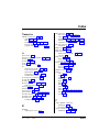
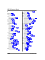
3 • Operation and Maintenance
ii
3.1
Preparing to Run . . . . . . . . . . . . . . . . .
3.1.1 Solvent Selection and Preparation . .
3.1.2 Filling the Solvent Reservoir . . . . .
3.1.3 Sample Preparation . . . . . . . . . . .
3.1.4 Cell Selection and Filling . . . . . . .
3.1.5 Bottle Loading . . . . . . . . . . . . .
3.1.6 Rinsing/Priming the System . . . . . .
3.1.7 Automatic Rinsing Between Samples
3.1.8 Operation with an External Device . .
.
.
.
.
.
.
.
.
.
3-1
3-1
3-2
3-3
3-5
3-10
3-11
3-12
3-13
3.2
Methods and Schedules . . . . . . . . . . . . . .
3.2.1 Creating Methods . . . . . . . . . . . . .
3-21
3-22
3.2.2
3.2.3
3.2.4
Example Methods . . . . . . . . . . . .
Creating Schedules . . . . . . . . . . . .
Example Schedules . . . . . . . . . . . .
3-27
3-31
3-33
3.3
Method Development Guidelines . . . . . . . . .
3-37
3.4
Running Extractions . . . . . . . . . . . .
3.4.1 Running Under Method Control
3.4.2 Running Under Schedule Control
3.4.3 Aborting a Run . . . . . . . . . .
.
.
.
.
3-39
3-39
3-42
3-43
3.5
Post-Extraction Procedures . . . . . . . . . . . .
3.5.1 Cleaning the Cells . . . . . . . . . . . .
3.5.2 Processing Extracts . . . . . . . . . . . .
3-44
3-44
3-44
3.6
Routine Maintenance . . . . . . . . . . . . . . .
3.6.1 Daily Maintenance . . . . . . . . . . . .
3.6.2 Periodic Maintenance . . . . . . . . . .
3-45
3-45
3-45
3.7
Shutdown . . . . . . . . . . . . . . . . . . . . . .
3-47
.
.
.
.
.
.
.
.
.
.
.
.
Doc. 031672-01 4/2000
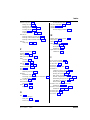
Contents
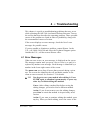
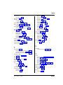
4 • Troubleshooting
4.1
Error Messages . . . . . . . . . . . . . . . . . . .
4-1
4.2
System Stopped . . . . . . . . . . . . . . . . . .
4-21
4.3
Liquid Leaks . . . . . . . . . . . . . . . . . . . .
4-22
4.4
Gas/Air Leaks . . . . . . . . . . . . . . . . . . .
4-25
5 • Service
5.1
Replacing the Cell PEEK Seal and
Teflon O-Ring . . . . . . . . . . . . . . . . . . .
5-2
5.2
Replacing Tubing and Fittings . . . . . . . . . .
5-3
5.3
Cleaning and/or Replacing Pump Check Valves
5-4
5.4
Replacing Piston Seals . . . . . . . . . . . . . .
5-7
5.5
Replacing the Pressure Relief Valve . . . . . . .
5-10
5.6
Replacing the Static Valve . . . . . . . . . . . .
5-11
5.7
Replacing Needles . . . . . . . . . . . . . . . . .
5.7.1 Vent Needle . . . . . . . . . . . . . . . .
5.7.2 Source Needle . . . . . . . . . . . . . .
5-12
5-12
5-14
5.8
Changing the Main Power Fuses . . . . . . . . .
5-15
5.9
Calibrating the Hydrocarbon Sensor . . . . . . .
5-16
5.10 Replacing the Hydrocarbon Sensor . . . . . . .
5-18
A • Specifications
A.1 Physical . . . . . . . . . . . . . . . . . . . . . . .
A-1
A.2 Environmental . . . . . . . . . . . . . . . . . . .
A-1
A.3 Electrical . . . . . . . . . . . . . . . . . . . . . .
A-1
A.4 Pneumatic . . . . . . . . . . . . . . . . . . . . .
A-1
A.5 Display and Keypad
. . . . . . . . . . . . . . .
A-2
A.6 Extraction Cells and Tray . . . . . . . . . . . . .
A-2
Doc. 031672-01 4/2000
iii
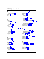
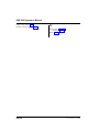
Contents
A.7 Collection Bottles and Trays . . . . . . . . . . . .
A-2
A.8 Interior Components . . . . . . . . . . . . . . . .
A-2
B • Installation
B.1
Facility Requirements . . . . . . . . . . . . . . . .
B-1
B.2
Installation Instructions . . . . . . . . . . . . . . .
B.2.1 Air/Nitrogen Connections . . . . . . . . .
B.2.2 Electrical Connections . . . . . . . . . . .
B-2
B-2
B-5
B.2.3
. . .
B-7
. . .
. . .
B-10
B-14
.
.
.
.
.
.
.
.
B-17
B-21
B-23
B-24
Module Setup . . . . . . . . . . . . . . . . . . . .
B-25
B.2.4
B.2.5
B.2.6
B.2.7
B.2.8
B.2.9
B.3
DX-LAN Interface:
10BASE-T Connections (Optional)
DX-LAN Interface:
BNC Connections (Optional) . . . .
Check Pressure Readings . . . . . .
Solvent Reservoir Compartment
Connections . . . . . . . . . . . . .
Cell and Rinse Tube Inspection . . .
Power-Up . . . . . . . . . . . . . . .
Rinsing/Priming the System . . . .
.
.
.
.
C • Diagnostic Screens
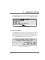
C.1
Power-Up Screen . . . . . . . . . . . . . . . . . .
C-1
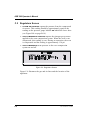
C.2
Regulators Screen . . . . . . . . . . . . . . . . . .
C-2
C.3
Error Log Screen . . . . . . . . . . . . . . . . . .
C-4
C.4
Hydrocarbon Calibration Screen . . . . . . . . . .
C-5
C.5
Leak Sensor Calibration and Status Screen . . . .
C-6
D • Reordering Information
iv
Doc. 031672-01 4/2000
Contents
E • TTL and Relay Control
E.1
TTL and Relay Output Operation . . . . . . . .
E-1
E.2
TTL Input Operation . . . . . . . . . . . . . . .
E.2.1 TTL Input Signal Modes . . . . . . . .
E-1
E-2
Index
Doc. 031672-01 4/2000
v
Contents
vi
Doc. 031672-01 4/2000
1 • Introduction
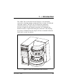
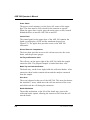
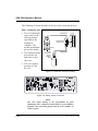
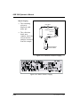
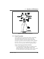
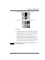
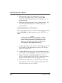
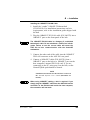
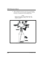
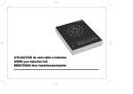
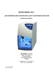
The ASE® 300 Accelerated Solvent Extractor is an automated
system for extracting organic compounds from a variety of solid and
semisolid samples. The ASE 300 accelerates the traditional
extraction process by using solvent at elevated temperatures.
Pressure is applied to the sample extraction cell to maintain the
heated solvent in a liquid state during the extraction. After heating,
the extract is flushed from the sample cell into a standard collection
bottle and is ready for analysis.
Figure 1-1. ASE 300 Accelerated Solvent Extractor
Doc. 031672-01 4/2000
1-1
ASE 300 Operator’s Manual
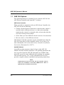
1.1 ASE 300 Options
Two optional products are available for use with the ASE 300: the
ASE Solvent Controller and AutoASE software.
ASE Solvent Controller
When operated in conjunction with an ASE Solvent Controller, the
ASE 300 can do the following:
•
Change solvents between extractions so that the same sample is
extracted with a different solvent, or so that each remaining
sample on the carousel is extracted with a solvent other than the
one used for the previous sample.
•
Select from up to four different solvent reservoirs for extractions.
•
Mix two, three, or four different solvents.
ASE Solvent Controller operation can be controlled from either the
ASE 300 front panel or from AutoASE release 2.0 (or later). For
more information, refer to the ASE Solvent Controller Installation
Instructions (Document No. 031277).
AutoASE Software
AutoASE provides computer control of up to eight ASE 300
modules and ASE Solvent Controllers. All operating parameters the
user can select from the ASE 300 front panel are available from
AutoASE, as well as some additional ones (printing, for example).
The AutoASE Software User’s Guide (Document No. 031259)
provides complete software installation and operating instructions.
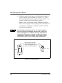
NOTE
Communication between the ASE 300 and AutoASE software
requires the installation of the DX-LAN interface. Refer to
Appendix B for installation instructions.
1-2
Doc. 031672-01 4/2000
1 • Introduction
1.2 About This Manual
Chapter 1, Introduction, introduces the ASE 300 and explains the
conventions used in this manual (including safety-related messages).
Chapter 2, Description, describes the physical aspects of the
ASE 300 and the extraction process.
Chapter 3, Operation and Maintenance, discusses operating
procedures and presents several examples of how to create and run
methods and schedules. Routine preventive maintenance
requirements are included.
Chapter 4, Troubleshooting, lists minor operating problems and
provides step-by-step procedures to isolate and eliminate their
sources.
Chapter 5, Service, presents step-by-step instructions for routine
service and parts replacement procedures.
Appendix A, Specifications, contains the ASE 300 specifications
and installation site requirements.
Appendix B, Installation, describes how to install the ASE 300.
Appendix C, Diagnostic Screens, describes the ASE 300 diagnostic
screens.
Appendix D, Reordering Information, lists spare parts.
Appendix E, TTL and Relay Control, describes relay and TTL
input and output functions.
1.2.1 Typefaces
•
Capitalized bold type indicates a front panel button:
Press Start to begin running the method.
•
Uppercase bold type indicates the name of a menu, a
screen, or an on-screen field:
Display the
METHOD EDITOR
Move the cursor to the
Doc. 031672-01 4/2000
screen.
EDIT#
field.
1-3
ASE 300 Operator’s Manual
1.2.2 Safety Messages and Notes
The ASE 300 meets European, EMC, and safety requirements
per Council Directives 73/23/EEC and 89/336/EEC, EN
61010-1:1993 (safety), EN 50082-1:1992 (susceptibility), and
EN 55011:1991 (emissions). The CE and GS safety label on
the ASE 300 attests to compliance with these standards.
To ensure operator safety, do not use the ASE 300 for any
applications other than those described in this manual. If
there is a question regarding appropriate usage, contact
Dionex before proceeding.
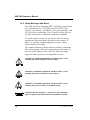
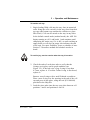
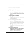
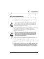
This manual contains warnings and precautionary statements
that, when properly followed, can prevent personal injury to
the user and/or damage to the ASE 300. Safety messages
appear in bold type and are accompanied by icons.
Indicates an imminently hazardous situation which, if not
avoided, will result in death or serious injury.
Indicates a potentially hazardous situation which, if not
avoided, may result in death or serious injury.
Indicates a potentially hazardous situation which, if not
avoided, may result in minor or moderate injury.
Indicates that the function or process of the instrument
may be impaired. Operation does not constitute a hazard.
1-4
Doc. 031672-01 4/2000
1 • Introduction
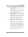
Informational messages also appear throughout this manual.
These are labeled NOTE and are in bold type:
NOTE
NOTES call attention to certain information. They alert
the user to an unexpected result of an action, suggest how
to optimize instrument performance, etc.
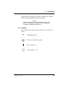
1.2.3 Symbols
The symbols below appear on the ASE 300 or on ASE 300
labels.
~
Alternating current
Protective conductor terminal
Power supply is on
Power supply is off
Doc. 031672-01 4/2000
1-5
ASE 300 Operator’s Manual
1-6
Doc. 031672-01 4/2000
2 • Description
•
Section 2.1 describes the operating features and components of
the ASE 300.
•
Section 2.2 describes the extraction process.
•
Section 2.3 describes the two operating modes for the ASE 300.
•
Section 2.4 describes both method and schedule control of the
ASE 300.
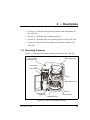
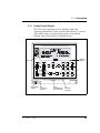
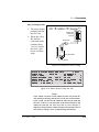
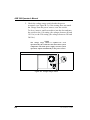
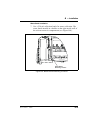
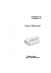
2.1 Operating Features
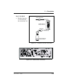
Figure 2-1 illustrates the main operating features of the ASE 300.
Oven Area
(Behind safety covers)
Electronics Area
(Behind upper door)
Control Panel
Pow er Switch
Cell Tray
Sam ple Extraction Cell
Bottle Tray
Solvent Reservoir
Com partm ent
Collection Bottle
Needle Mechanism
Figure 2-1. ASE 300 Operating Features
Doc. 031672-01 4/2000
2-1
ASE 300 Operator’s Manual
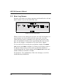
Power Switch
The power switch actuator is at the lower left corner of the upper
door. The door must be fully closed for the actuator to operate.
When the upper door is open, press the main power switch, located
behind the door, to turn the ASE 300 on and off.
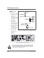
Control Panel
The control panel on the upper door of the ASE 300 contains the
liquid crystal display (LCD) and the membrane keypad (see
Figure 2-2). The upper door provides access to the ASE 300
electronics.
Solvent Reservoir Compartment
The lower door provides access to the solvent reservoir, the waste
bottle, and the pressure gauges.
Cell Tray and Extraction Cells
The cell tray, on the upper right of the ASE 300, holds the sample
extraction cells. The prepared sample is loaded into these cells.
Bottle Tray and Collection Bottles
The bottle tray, on the lower right, holds the collection bottles. After
extraction, these bottles contain solvent and the analytes extracted
from the sample.
Oven Area
The oven is housed at the rear of the ASE 300. This area also houses
the AutoSeal arms, which move the cell into and out of the oven,
and which seal the cell during the extraction.
Needle Mechanism
The needle mechanism, at the left of the bottle tray, pierces the
collection bottle septum, allowing the extract to flow from the cell
into the bottle.
2-2
Doc. 031672-01 4/2000
2 • Description
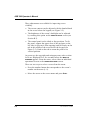
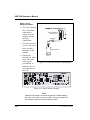
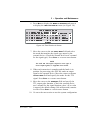
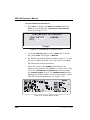
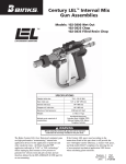
2.1.1 Control Panel Display
The LCD, also called the screen, displays status and
operating information. Fields on the screen that are in reverse
video (blue letters on white background) can be edited.
Normal video fields display information only.
A S E 3 0 0 A C C E L E R ATE D S O LV E N T E X T R A C TO R
/2$' 0(7+2'6&+('8/(
&20081,&$7,21
7,0(
)81&7,21 ,1
TIME
FUNCTION
IN0(18
&855(17 67$786
',$*1267,&
0(18
8 ',$*1267,&
0(7+2' (',725
7,0(
)81&7,21
,1
(;71/ INTERFACE
,17(5)$&(
9 EXTNL
6&+('8/( (',725
(;71/ ,17(5)$&(
02'8/( 6(783
M em b ran e
K eypad
LC D
Pow er Sw itch
A ctu ator
Tab
(for o pening
the d oo r)
K nob
(for ad justin g th e
screen con trast)
Tab
(for tiltin g
the p an el)
Figure 2-2. ASE 300 Control Panel
Doc. 031672-01 4/2000
2-3
ASE 300 Operator’s Manual
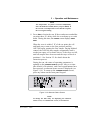
Three adjustments are available for improving screen
visibility:
•
The screen contrast can be adjusted with the knurled knob
in the recess below the keypad (see Figure 2-2).
•
The brightness of the screen’s backlight can be adjusted
by resetting this option on the MODULE SETUP screen (see
Section B.3).
•
The control panel can be tilted to four positions. To tilt
the panel, support the upper door of the enclosure at the
left side (to prevent it from opening) and lift firmly on the
tab in the middle of the recess below the keypad (see
Figure 2-2). Push on the tab to return the panel to its
vertical position.
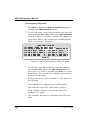
At power-up, the copyright and microprocessor code revision
levels are displayed for a few seconds before the MENU OF
SCREENS appears. From the menu, select either an individual
operational screen or the DIAGNOSTIC MENU screen.
There are two ways to select a screen from the menu:
2-4
•
Press the number button that corresponds to the screen’s
number on the menu (1–9).
•
Move the cursor to the screen name and press Enter .
Doc. 031672-01 4/2000
2 • Description
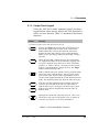
2.1.2 Control Panel Keypad
Unless the ASE 300 is under computer control, pressing a
keypad button either directly affects ASE 300 operation or
affects a screen function. Table 2-1 summarizes the button
functions.
Button
Function
The following buttons affect ASE 300 operation directly:
Trays
(F re e S pin)
Trays
(E nga ge d)
Pressing the Trays button toggles the cell and bottle trays
between the engaged and free spin modes. LEDs on the
button indicate the current mode. When the left LED is
lighted, the bottle and cell trays can be rotated manually.
Switch to free spin during loading and unloading of bottles
and cells.
When the right LED is lighted, the tray drive mechanisms
are engaged and cannot be moved manually. Toggling from
free spin to engaged causes the trays to rotate to the home
position (i.e., bottle 1 and cell 1 are ready for the next run).
Starting a run automatically engages the trays. The Trays
button is disabled during a run.
Starts a manual rinse cycle, which is used to prime the pump
and to rinse after a solvent change. The trays rotate to the
nearest rinse bottle and rinse tube. Approximately 5 mL of
solvent is then pumped through the system and into the rinse
bottle. This button functions only when the ASE 300 is idle.
S tart
(Idle)
S tart
Starts the currently loaded method or schedule. When the
system is idle, the LED on the left side of the button is
lighted. When a run is in progress, the LED on the right is
lighted. This button is disabled when the ASE 300 is in
Remote mode.
(R u nnin g)
Interrupts the current run. The pump turns off, valves close,
and all flow stops. The screen displays a list of options for
selection. See Section 3.4.3 for more information.
Table 2-1. Front Panel Button Functions
Doc. 031672-01 4/2000
2-5
ASE 300 Operator’s Manual
Button
Function
The following buttons control functions:
From the SCHEDULE EDITOR screen, press Alt followed by
Select ∆ to delete the current line and move up the lines
below the deleted line. Press Alt followed by Select ∇ to
insert a new line. This button is disabled when the ASE 300
is in Remote mode.
Removes the value from the current entry field. This button
is disabled when the ASE 300 is in Remote mode.
6HOHFW
6HOHFW
The Select buttons cycle between predetermined options in
entry fields. To confirm the selected value, press Enter or
move the cursor out of the field by pressing an arrow button.
In fields that have predetermined numeric choices, Select ∆
increases the value by one unit and Select ∇ decreases the
value by one unit. Holding down a Select button increases
(or decreases) the value continuously.
The arrow buttons move the cursor in the direction of the
arrow to the next entry field, if one exists. At the end of a
line, the left arrow wraps the cursor around to the next entry
field on the line above; the right arrow wraps the cursor to
the next entry field on the line below. The up and down
arrows do not wrap around.
After entering a new value in an entry field, pressing an
arrow button to move the cursor to another field saves the
change.
Displays a context-sensitive help screen.
Displays a list of the available screens.
The numeric buttons enter the selected number into the
current entry field. From a menu, pressing a numeric button
opens the corresponding screen.
Saves changes made in entry fields. When a menu screen is
displayed, pressing Enter opens the highlighted screen.
Table 2-1. Front Panel Button Functions (continued)
2-6
Doc. 031672-01 4/2000
2 • Description
NOTE
Appendix D contains part numbers for cells, bottles,
and other consumable accessories.
2.1.3 Sample Cells, Rinse Tubes, and Cell Tray
The cell tray holds 12 sample cells and two rinse tubes.
Sample cells are available in these sizes: 34 mL, 66 mL, and
100 mL. Interchangeable caps screw onto each end of the cell
body and are hand-tightened. Inside each cap is a stainless
steel frit and a PEEK seal. During a run, the cell caps are
compressed to form a tight seal between the caps and the cell
body.
Each cell cap contains an external O-ring. Teflon® O-rings
(P/N 049457, pkg. of 50) are standard. Use Viton® O-rings
(P/N 056325, pkg. of 50) for high temperature applications,
such as dioxins.
If the external O-ring is Viton, do not use acetone.
Install the sample cells in any order. During a run, sensors
determine the cell size in each tray position.
To avoid personal injury, exercise caution when the tray is
in motion.
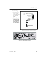
Rinse tubes are small-diameter metal tubes that fit into the
two rinse positions in the cell tray (see Figure 2-3). During a
rinse cycle, the tray rotates to the nearest rinse position that
ensures that the heated cells remain behind the safety cover
over the oven (see Figure 2-1). Solvent passes directly
through the rinse tube during the cycle.
Doc. 031672-01 4/2000
2-7
ASE 300 Operator’s Manual
R in se Tu be
C ell
Figure 2-3. Rinse Tubes
2.1.4 Collection Bottles, Rinse Bottles, and Bottle Tray
The bottle tray holds 12 collection bottles and one rinse
bottle.
The 250 mL collection bottle (P/N 056284, pkg. of 12) is
made of clear glass. Each collection bottle cap has a
solvent-resistant septum. During a run, the needle mechanism
pierces the septum, creating a liquid flow path from the
sample cell to the collection bottle.
The rinse position (labeled R1) accommodates one standard
250 mL collection bottle. During a rinse cycle, the tray
rotates to the rinse position. Before starting the rinse, if the
bottle sensors determine that the rinse bottle is absent or full,
the screen displays an error message. Solvent is then pumped
through the system and collected in the rinse bottle.
To avoid personal injury, exercise caution whenever the
tray is in motion.
2-8
Doc. 031672-01 4/2000
2 • Description
2.1.5 Solvent Reservoir Compartment
The compartment behind the front lower door (see Figure
2-1) contains the solvent reservoir, waste bottle, and pressure
gauges.
The ASE 300 Ship Kit (P/N 056667) includes a 2-liter glass
reservoir with shatterproof plastic coating (P/N 045901) and a
bottle cap assembly (P/N 051977) with tubing and fittings for
connecting the reservoir to the ASE 300.
NOTE
When an ASE Solvent Controller is in use, install the
solvent reservoirs in the Solvent Controller.
A 250 mL collection bottle is used to collect waste. The
waste bottle sits in a holder on the right side of the reservoir
compartment. Two vent lines, one from the pressure relief
valve and one from the needle mechanism, are connected to
the top of the waste bottle holder. The waste bottle collects
the small amounts of solvent vented through the two lines.
A vent outlet line is also connected to the waste bottle holder.
Gas is vented out this line to the rear panel, which can be
connected to a hood. The Ship Kit includes additional vent
tubing for this purpose.
Check the waste bottle daily and empty whenever necessary.
Doc. 031672-01 4/2000
2-9
ASE 300 Operator’s Manual
2.1.6 Electronics Area
The ASE 300 electronics area is located behind the upper
front door (see Figure 2-1). To open the door, pull on the tab
located to the right of the main power actuator (see
Figure 2-2).
A strip of eight 2-pin connectors (two relay outputs, two TTL
outputs, and two TTL inputs) on the CPU card allows the
ASE 300 to communicate with an external sample preparation
device. See Section 3.1.8 for details about implementing this
feature.
Do not remove any of the electronics cards. There are no
user-serviceable components on the cards. If servicing is
required, it must be performed by qualified personnel and
appropriate electrostatic discharge (ESD) handling
procedures must be followed.
2-10
Doc. 031672-01 4/2000
2 • Description
2.2 Extraction Process
Before starting an extraction, perform the following steps. Refer to
Chapter 3 for instructions.
•
Prepare samples and load them into the extraction cells.
•
Place cells in the cell tray.
•
Place collection bottles in the bottle tray.
•
Create a method.
•
Load the method.
The remainder of this section describes the automatic portion of the
extraction process—the steps that the ASE 300 performs after you
press Start to begin a run.
The extraction process consists of eight main steps:
•
Loading the cell into the oven
•
Filling the cell with solvent
•
Heating the cell (equilibration)
•
Static extraction
•
Flushing with fresh solvent
•
Purging solvent from the system
•
End relief
•
Unloading the cell
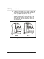
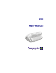
Figure 2-4 shows the solvent and gas flow path through key
components of the ASE 300.
Doc. 031672-01 4/2000
2-11
ASE 300 Operator’s Manual
Left-Side Panel D oor
Transducer
Relief Valve
Oven/A utoSeal Area
(under top-right cover)
AutoSeal Arm
Check Valve
Sample Cell or
Rinse Tube
Purge Valve
Pump
Solenoids
Pump
N eedle M echanism
(on right-inside panel)
Static
Valve
Regulator
50 psi
To N 2
Sup ply
Prime
Valve
Tee
To Vent on
Rear Panel
To Vent on
Rear Panel
Solvent
Reservoir
Waste
Bottle
Collection
Bottle
Solvent R eservoir
C om partm ent
Gas Lines
Solvent Lines
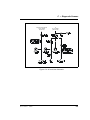
Figure 2-4. ASE 300 Schematic
During the extraction process, the CURRENT STATUS screen displays
the step being run, as well as other operating parameters. Figure 2-5
is an example of the CURRENT STATUS screen. Table 2-2 describes the
screen parameters.
6<67(0 67$786 ),//,1* &(//
/2&$/
&21752/
0(7+2'
6&+('8/(
67(3 7,0(
0(7+2'
7(03(5$785( °&
&(//
35(6685(
SVL &(// 6,=( 67$7,& 2 3803
2
%77/
385*( & 5(/,() &
92/80( P/
Figure 2-5. Current Status Screen
2-12
Doc. 031672-01 4/2000
2 • Description
Parameter
Description
SYSTEM STATUS
Current step (load, fill, heat, static, flush, purge, unload)
Current control type (method or schedule)
Step’s programmed time is first, followed by the elapsed
time
Programmed temperature is first, followed by the current
temperature
Programmed pressure is first, followed by the current
pressure
Status of valves (C=closed, O=open)
CONTROL
STEP TIME
TEMPERATURE
PRESSURE
STATIC PUMP
PURGE RELIEF
SCHEDULE
METHOD
CELL
CELL SIZE
BTTL
VOLUME (mL)
Current schedule (if any)
Current method
Current cell
Size of the cell (34 mL, 66 mL, or 100 mL)
Current bottle
Approximate amount of solvent delivered by the pump
Table 2-2. Current Status Screen Parameters
If no keypad buttons are pressed for a specified duration, an
alternate status screen replaces the CURRENT STATUS screen (see
Figure 2-6). Press any button to return to the CURRENT STATUS
screen. To change the time delay for displaying the alternate status
screen or to disable the screen, see Section B.3.
BTTL
Figure 2-6. Alternate Status Screen
Doc. 031672-01 4/2000
2-13
ASE 300 Operator’s Manual
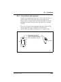
The following sections describe each step in the extraction process.
Step 1: Loading the Cell
•
The cell and bottle
trays rotate to the
initial positions
specified in the
method or
schedule. The
needle mechanism
pierces the bottle.
•
The AutoSeal arms
pick up the cell
and move it into
the oven.
•
The oven applies
pressure to seal
the cell.
AutoSeal Arm
Oven
Cell w ith Sample
M oved to Oven
Solvent
AutoSeal Arm
Needle
M echanism
Pierces
Collection
Bottle
Figure 2-7. Extraction Process: Loading
/2&$/
°
%77/
Figure 2-8. Status Screen: Load Cell
NOTE
The oven begins heating to the programmed set point
immediately after a method is loaded (before you press Start to
begin the run). Cell loading begins when the oven is within 5 °C
of the set point.
2-14
Doc. 031672-01 4/2000
2 • Description
Step 2: Filling the Cell
•
•
The pump begins
pumping solvent
into the cell.
When the cell is
full and the
collection bottle
contains about
7 mL of solvent,
the static valve
closes and flow
stops.
From
Pum p
Oven
Pum p On
Sam ple Cell
Filled with
Solvent
Static Valve
Open
Collection Bottle
7 m L Sensor
Figure 2-9. Extraction Process: Filling
6<67(0 67$786 ),//,1* &(//
/2&$/
&21752/
0(7+2'
6&+('8/(
67(3 7,0(
0(7+2'
7(03(5$785( °&
&(//
35(6685(
SVL &(// 6,=( 67$7,& 2 3803
2
%77/
385*( & 5(/,() &
92/80( P/
Figure 2-10. Status Screen: Filling the Cell
NOTE
If the sample cell does not fill within the time-out period, the
ASE 300 stops running, and advances to the next cell and bottle.
If the second cell does not fill within the time-out, the ASE 300
advances to the next cell and bottle. If the third cell fails to fill
within the time-out, all runs stop and an error message is
displayed. The problem is usually caused by a block in the solvent
flow path (see Chapter 4 for troubleshooting information).
Doc. 031672-01 4/2000
2-15
ASE 300 Operator’s Manual
Steps 3 and 4:
Heating and Static
•
•
•
The cell is heated
for a fixed time
(optional) to
ensure that the
sample reaches
thermal
equilibrium.
Sam ple Cell Heated
Under Pressure
Static Valve
Closed
The static period
occurs. Select the
time (usually 5
minutes) in the
method.
During the
heating and static
steps, the static
valve opens
periodically to
maintain the set
point pressure in
the cell.
Oven On
Pump On
Collection Bottle
Figure 2-11. Extraction Process: Heating/Static
/2&$/
PLQ
°
%77/
Figure 2-12. Status Screen: Heating
NOTE
When the cell pressure exceeds the set point by 1.4 MPa (200 psi),
the static valve opens to relieve pressure. Any solvent that exits
the cell then is directed into the collection bottle.
2-16
Doc. 031672-01 4/2000
2 • Description
Step 5: Flushing
•
•
The static valve
opens and the
extract flows into
the collection
bottle.
Fro m
Pump
Pump O n
S o lven t F lu sh ed
Th roug h Cell
Fresh solvent is
pumped through
the cell (usually
50 to 100% of
the cell volume).
S tatic Valve
O p en
S o lven t an d E xtract
C ollected in B o ttle
Figure 2-13. Extraction Process: Flushing
/2&$/
°
34
B TTL:
40
Figure 2-14. Status Screen: Flushing
Doc. 031672-01 4/2000
2-17
ASE 300 Operator’s Manual
Step 6: Purging
•
•
The remaining
solvent is
displaced with
purge gas.
Purge Valve
Open
N2
Last Solvent Purged
from Cell
The collection
bottle now
contains all of the
solvent and the
analytes extracted
from the sample.
Static Valve
Open
Solvent and Extract
Collected in Bottle
Figure 2-15. Extraction Process: Purging
/2&$/
6(&
°
BTTL:
34
45
Figure 2-16. Status Screen: Purging
2-18
Doc. 031672-01 4/2000
2 • Description
Step 7: End Relief
•
P ressure Relief Valve
Residual pressure
is released from
the extraction cell.
O pen
Residual P ressure
Released from Cell
S ta tic Valve
O pen
S olvent and Extract
Colle cted in Bottle
Figure 2-17. Extraction Process: End Relief
(1'
5(/,()
/2&$/
°
%77/
34
45
Figure 2-18. Status Screen: End Relief
Doc. 031672-01 4/2000
2-19
ASE 300 Operator’s Manual
Step 8:
Unloading the Cell
To Waste
•
Pressure is vented
from the system.
•
The cell is
unloaded from the
oven and returned
to the tray.
•
•
•
The needle
mechanism is
removed from the
collection bottle.
The trays advance
to their next
positions and the
next run starts.
The ASE 300
stops when all
runs are
completed.
Pressure Relief
Valve Open
Cell Rem oved
From Oven
Needles
Rem oved
From Bottle
Collection B ottle
Figure 2-19. Extraction Process: Unloading the Cell
/2&$/
°
%77/
Figure 2-20. Status Screen: Unloading
Cells are extremely hot after an extraction. Allow the cells
to cool for at least 15 minutes before handling, especially
if the cells were heated over 50 °C.
2-20
Doc. 031672-01 4/2000
2 • Description
During an extraction, solenoids turn the pump flow on and off. In
addition, the following valves control solvent flow and pressure in
the system:
•
The static valve controls the flow of solvent to the collection
bottle. Pressure in the cell increases when the pump is on and the
static valve is closed.
•
The purge valve controls gas pressure to the cell.
•
The pressure relief valve releases any residual pressure after an
extraction.
•
The prime valve controls gas pressure to the solvent bottle.
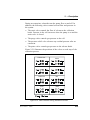
Figure 2-21 illustrates the positions of the valves at each step of the
extraction process.
LO A D /U N LOA D
PU R GE
FILL
EN D R ELIE F
H E AT/S TATIC
ID LE
FLU SH
R IN S E
Figure 2-21. Valve Positions During Extraction Process
Doc. 031672-01 4/2000
2-21
ASE 300 Operator’s Manual
2.3 Operating Modes
The ASE 300 has two operating modes: Local and Remote. Select
the mode from the MODULE SETUP screen (see Section B.3). The
CURRENT STATUS screen displays the selected mode (see Figure 2-5).
2.3.1 Local Mode
When the ASE 300 power is turned on, it defaults to Local
mode. In Local mode, operation is controlled by commands
input directly from the ASE 300 keypad.
2.3.2 Remote Mode
In Remote mode, the ASE 300 accepts operating commands
from AutoASE software version 2.0 (or later). The CURRENT
STATUS screen displays the method steps as they are executed.
In Remote mode, the following conditions apply:
•
Only three ASE 300 keypad buttons are functional: Trays,
Rinse, and Abort.
•
The LOAD METHOD OR SCHEDULE screen is not accessible.
Although other screens can be displayed, only one field
can be edited: the operating mode can be toggled from
Remote to Local on the MODULE SETUP screen.
•
All global rinse commands selected from the keypad are
disregarded.
•
Selecting Remote mode does not override the ASE 300
parameters specified for operation with an external sample
preparation device (see Section 3.1.8). Similarly, if you
select the YES option for BYPASS HEATUP or REDUCE
RELIEF on the MODULE SETUP screen, selecting Remote
mode does not override this.
Sending an operating command from AutoASE automatically
switches the ASE 300 to Remote mode, if it is not already
selected. To return to LOCAL mode, open the MODULE SETUP
screen and reset the mode.
2-22
Doc. 031672-01 4/2000
2 • Description
2.4 Method and Schedule Control
NOTE
This section describes how to create methods and schedules from
the ASE 300 front panel. For instructions on creating methods
and schedules from AutoASE software, refer to the AutoASE
manual or online Help.
Before running an extraction, you must create a method that defines
operating conditions for the run. A method specifies the following
parameters:
•
Oven temperature
•
Static time
•
Amount of solvent to flush through the cell
•
Solvent types and percentages (if the ASE Solvent Controller is
installed)
•
Purge time
•
Cycles
The ASE 300 can store up to 24 methods. Section 3.2.1 describes
how to create methods from the ASE 300 front panel.
For a series of extractions, you can define a schedule of runs. A
schedule specifies the method to run on each sample in the schedule,
the sample cell assigned to each collection bottle, and the rinse
status after each sample run. The ASE 300 can store up to 24
schedules. Section 3.2.3 describes how to create schedules from the
ASE 300 front panel.
The ASE 300 provides two control modes:
•
Method control runs the same method on each consecutive
sample loaded in the tray.
•
Schedule control runs a series of methods according to the
schedule definition.
Doc. 031672-01 4/2000
2-23
ASE 300 Operator’s Manual
2-24
Doc. 031672-01 4/2000
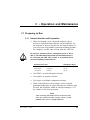
3 • Operation and Maintenance
3.1 Preparing to Run
3.1.1 Solvent Selection and Preparation
•
When developing a new extraction method, select a
solvent or solvent mixture that has a high solubility for
the analytes of interest, but not for the sample matrix. If
you have been using another extraction method (Soxhlet,
for example), use the same solvent with the ASE 300.
Do not use solvents with an autoignition point of 40 to
300 °C. The table below lists some solvents that should not
be used with the ASE 300. If there is a question about
solvent suitability, contact Dionex.
Solvents Not to Use
Autoignition Point
Carbon disulfide
Diethylether
1,4-Dioxane
100 °C
180 °C
180 °C
CS2
(C2H5) 2O
C 4H8O2
•
Use HPLC- or pesticide-grade solvents.
•
Use organic or aqueous solvents.
•
Use single- or multiple-component solvents.
•
Weak acids and bases (for example, acetic acid and
potassium hydroxide) or other noncorrosive additives may
be used, but should be added in small percentages (<5%
by volume) to the solvent system.
NOTE
After extracting with acidic solvents or basic solvents,
rinse the system with 100% organic solvent or with
distilled water before overnight shutdown.
Doc. 031672-01 4/2000
3-1
ASE 300 Operator’s Manual
•
Solvents do not usually need to be degassed. Degas
solvents only if the analyte of interest oxidizes easily.
•
If the extraction cell cap external O-ring is Viton, do not
use acetone.
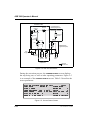
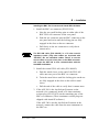
3.1.2 Filling the Solvent Reservoir
NOTE
When using an ASE Solvent Controller, disregard this
section and follow the instructions in the Solvent
Controller manual.
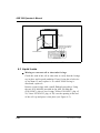
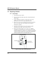
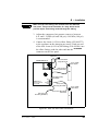
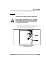
1. Fill the solvent reservoir with prepared solvent and set it
inside the ASE 300 solvent reservoir compartment (see
Figure 2-1).
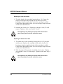
Use only Dionex solvent reservoirs (1-liter, P/N 045900;
2-liter, P/N 045901). These are glass reservoirs with a plastic,
shatterproof coating. Make sure the pressure applied to
the reservoirs does not exceed 0.07 MPa (10 psi).
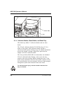
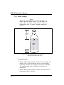
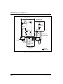
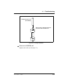
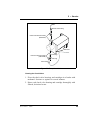
2. Insert the outlet line extending from the underside of the
reservoir cap assembly into the reservoir (see Figure 3-1).
Make sure that the in-line filter rests on the bottom of the
reservoir. This prevents air from being drawn through the
line. If needed, gently pull on the outlet line to bring
more tubing into the reservoir.
3. Make sure that the solvent level in the reservoir is below
the gas inlet line (see Figure 3-1). This prevents solvent
from coming into contact with pneumatic valves.
4. Hand-tighten the lock ring cap securely over the stopper.
5. When refilling the reservoir, remove the cap and stopper
and remove the reservoir from the compartment. It is not
necessary to disconnect the inlet and outlet lines.
3-2
Doc. 031672-01 4/2000
3 • Operation and Maintenance
Figure 3-1. Solvent Reservoir Connections
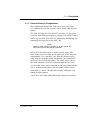
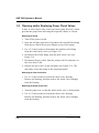
3.1.3 Sample Preparation
Some samples must be mixed with a drying or dispersing
agent before being loaded into the cells. If you have
successfully followed a particular sample pretreatment
procedure for another extraction method, continue using this
procedure. However, if you are preparing a new sample or
have never run an extraction, follow the guidelines below.
Drying or Dispersing Agent Selection Guidelines
•
Doc. 031672-01 4/2000
Two drying and dispersing agents are referred to in the
section that follows: sodium sulfate (Na2 SO4 ) and
pelletized diatomaceous earth (DE). Of these, DE is easier
to work with because it dries samples more quickly,
3-3
ASE 300 Operator’s Manual
provides a cleaner transfer of the mixtures to the cell, and
extracts well. Although sodium sulfate is more readily
available, it tends to clump the samples, making transfer
more difficult.
•
The use of sodium sulfate with very wet samples (30%
moisture) may result in clogging of the frits in the cell
with recrystallized sodium sulfate, particularly if a mixed
solvent with acetone is used. In these cases, use DE as a
drying agent and mix it with the sample before loading
into the extraction cell. (Alternately, DE can be used as a
drying agent in the cell in place of sodium sulfate for all
levels of moisture.)
•
For very wet samples, regardless of which drying agent is
used, you must add sodium sulfate to the bottles after
collection and then pass the extracts through a drying
column or drying cartridge to dry the extract completely.
At the temperatures used during ASE 300 extractions,
more water is co-extracted than with other extraction
procedures. To ensure good analyte recovery, thoroughly
rinse the sodium sulfate from the bottle and the cleanup
column.
•
Never use sodium sulfate with polar extraction solvents,
such as methanol. At the temperatures used during
ASE 300 extractions, polar solvents are dissolved by
sodium sulfate.
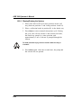
Sample Preparation Guidelines
The following mixtures are recommendations only; adjust the
proportions as required.
•
If the sample appears dry, use one of these mixtures:
4 grams sample to 1 gram DE
4 grams sample to 4 grams Na2SO4
3-4
Doc. 031672-01 4/2000
3 • Operation and Maintenance
•
If the sample appears wet, use one of these mixtures:
4 grams sample to 2 grams DE
4 grams sample to 8 grams Na2SO4
•
If the sample is pure liquid, use 5 grams sample to
3 grams DE
Mix the sample and the DE or Na 2SO 4 thoroughly in a small
bottle, beaker, or mortar.
3.1.4 Cell Selection and Filling
Three cell sizes are available: 34 mL, 66 mL, and 100 mL.
The cell size does not affect the extraction time, but it does
determine how much solvent is used; because the cell is filled
with solvent during the extraction, larger cells require more
solvent. Also, a cell that is partially filled with sample
requires more solvent than a full cell.
In general, when choosing a cell size:
•
Select the smallest cell that holds enough sample to
produce accurate extraction results.
•
Take into account any drying or dispersing agents,
because these increase the volume of the sample.
•
When preparing the sample, make sure that the drying or
dispersing agent and sample are thoroughly mixed.
Cell Filters
A disposable cellulose or glass-fiber filter must be installed
in the cell before sample is loaded. The filter prevents
blockage of the stainless steel frit in the bottom cap.
Cellulose filters are appropriate for most extraction methods
using organic solvents. Glass-fiber filters are typically used
for aqueous extractions, where cellulose may provide
inadequate filtration or may be a source of interference with
the analytical technique.
Doc. 031672-01 4/2000
3-5
ASE 300 Operator’s Manual
To insert the filter:
Always hand-tighten the bottom cell cap onto the cell body
before installing the filter. Do not place the filter in the
bottom cap before installing the cap; this creates an
improper seal and allows leaks.
NOTE
It may be helpful to use the Dionex logo and serial number
etched on the cell body to identify the direction of fluid
flow. For example, designate the end closer to the logo and
serial number as the top, and then follow that convention
when installing the filter and loading cells into the tray.
Or, use a marking pen to draw an arrow on the cell to
indicate the direction of flow.
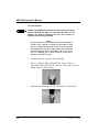
1. Unscrew the top cap from the cell body.
2. Place a cellulose filter (P/N 056780, box of 100) or
glass-fiber filter (P/N 056781, box of 100) in the cell at a
slight angle, as shown here:
3. Position the insertion tool (P/N 056929) over the filter:
3-6
Doc. 031672-01 4/2000
3 • Operation and Maintenance
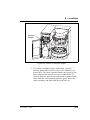
4. Slowly push the insertion tool into the cell:
5. Make sure the filter is in full contact with the cell:
To fill the cell:
1. Using an aluminum funnel (P/N 056699), carefully load
the sample into the cell. Be sure to keep the threads on
the cell body and cap as clean as possible; this prevents
thread fouling and extends the life of the cell.
2. If desired, fill any void volume in the cell with an inert
material, such as Ottawa sand (Fisher S23-3). This
reduces the amount of solvent used during the extraction.
3. Screw the top cap onto the cell body and hand-tighten. Do
not use a wrench or other tool to tighten the cap.
Hand-tighten the cell caps. The use of a wrench or other
tool can damage the cell.
Doc. 031672-01 4/2000
3-7
ASE 300 Operator’s Manual
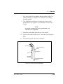
4. Check the ends of each cap to verify that the O-rings are
in place and in good condition (see Figure 3-2). If the
hole size of any O-ring is less than 0.5 mm, replace it. If
a white Teflon O-ring is discolored, replace it.
Remove worn O-rings with a small flathead screwdriver.
Place a new O-ring over the opening in the end of the cell
cap and press it into place, using the tool (P/N 049660)
provided in the Ship Kit.
Do not attach any labels to the cell. The cells fit snugly in
the oven during the extraction process and a label may
cause misalignment. In addition, the high temperatures
used during extraction can damage the label. For sample
identification, reference the Dionex serial number etched
on the cell or write on the cell body with a marking pen.
C heck ends of ce lls and
rinse tubes for O -rings
(Teflon : P /N 049457, P kg . 50;
V ito n: P /N 056325, P kg . 50)
R inse Tub e
C ell
Figure 3-2. O-Ring Inspection
3-8
Doc. 031672-01 4/2000
3 • Operation and Maintenance
To load the cell tray:
1. Begin loading filled cells into the tray slots in numerical
order. Hang the cells vertically in the tray slots from their
top caps (the bottom cap contains the cellulose or glassfiber filter). Cells can be mixed on the tray in any order.
In the default control mode (method mode), the ASE 300
begins running at cell 1 and bottle 1 and continues until
completing the entire tray, if it is full, or until reaching an
empty bottle or cell slot (an empty slot indicates the end
of the run). For more flexibility, create a schedule of runs.
Section 3.2 describes method and schedule modes in
detail.
To avoid injury, exercise caution when the tray is in motion.
2. Check the ends of each rinse tube to verify that the
O-rings are in place and in good condition (see
Figure 3-2). If the hole size of any O-ring is less than
0.5 mm, replace it. If a white Teflon O-ring is discolored,
replace it.
Remove worn O-rings with a small flathead screwdriver.
Place a new O-ring over the opening in the end of the cell
cap and press it into place, using the tool (P/N 049660)
provided in the Ship Kit.
3. Load the rinse tubes into the two open slots between cell
positions 3 and 4 and positions 9 and 10.
Doc. 031672-01 4/2000
3-9
ASE 300 Operator’s Manual
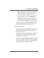
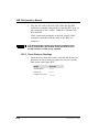
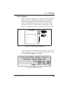
3.1.5 Bottle Loading
NOTE
During the extraction process, sensors determine if a
bottle is present, contains solvent, or is full. Figure 3-0
shows where to attach a bottle label, or write an
identification name or number, without blocking the
sensors.
5.25 cm
(2.07 in)
Label
Okay
1.27 cm
(0.05 in)
Figure 3-3. Acceptable Bottle Label Location
(Bottle not shown actual size)
To load the bottles:
3-10
•
When running under method control, for each sample cell
loaded, load a collection bottle into the corresponding
bottle tray position. For example, if positions 1 through
10 contain sample cells, load bottles in positions 1
through 10.
•
When running under schedule control, load the bottles as
programmed in the schedule.
Doc. 031672-01 4/2000
3 • Operation and Maintenance
•
Load a bottle into the rinse slot (labeled R1).
Check the rinse bottle after each series of runs; if necessary,
empty the bottle before starting the next series.
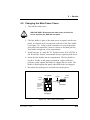
3.1.6 Rinsing/Priming the System
Pressing the Rinse button on the keypad starts a manual rinse,
or prime, cycle. During the cycle, the cell tray rotates to the
nearest rinse tube, the bottle tray rotates to a rinse position,
and approximately 5 mL of solvent is pumped through the
system.
Run a rinse cycle at the following times:
•
After initial setup
NOTE
When running with an ASE Solvent Controller, the
system automatically rinses with 9 mL of solvent when
the Start button is pressed. The rinse is also 9 mL if
the schedule calls for a change of solvent.
•
After the ASE 300 has been shut down for more than a
day, or when the solvent lines contain bubbles
•
After refilling the solvent reservoir
•
After changing solvents (rinse twice to remove all of the
old solvent)
To set up the ASE 300 to automatically run a rinse between
sample extractions, see Section 3.1.7.
Doc. 031672-01 4/2000
3-11
ASE 300 Operator’s Manual
3.1.7 Automatic Rinsing Between Samples
An automatic rinse cycle can run between sample extractions.
The automatic rinse cycle is identical to the manual rinse
cycle (see Section 3.1.5), except that only 2 mL of solvent is
pumped through the system during an automatic rinse cycle.
•
When running under method control, you can set up the
ASE 300 to run an automatic rinse cycle after each
sample extraction (see the steps below).
•
When running under schedule control, you must specify
on each line in the schedule whether an automatic rinse
cycle is performed (see Section 3.2.3).
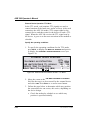
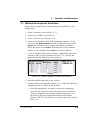
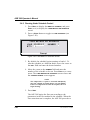
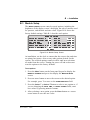
To set up automatic rinses during method control:
1. Verify that the rinse tubes are in place. Verify that an
empty rinse bottle is in place.
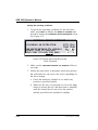
2. Press Menu to display the MENU OF SCREENS and press 5
to display the MODULE SETUP screen.
3. Move the cursor to the METHOD RINSE field and press a
Select button to toggle the field to ON (see Figure 3-4).
Press Enter or a cursor arrow button. A rinse cycle is then
performed after each sample extraction run. Method rinse
remains the default until toggled off from the MODULE
SETUP screen.
02'8/( 6(783
62/9(17 6(/(&7 12
02'(
/2&$/
'$7(
6&51 %$&./,*+7 +,*+
7,0(
.(< 6281'
21
0(7+2' 5,16( 21
(5525 6281'
21
'(7$,/ 6&5((1 35(6685( 81,76 36,
5('8&( 5(/,() 12
%<3$66 +($783 12
3URPSW
Figure 3-4. Module Setup Screen (Method Rinse On)
3-12
Doc. 031672-01 4/2000
3 • Operation and Maintenance
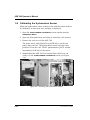
3.1.8 Operation with an External Device
An external sample preparation device (such as a device
equipped with a robotic arm) can be interfaced to the
ASE 300 to perform these tasks:
•
Access collection bottles containing sample processed by
the ASE 300, or
•
Insert cells into the ASE 300 cell tray and/or remove cells
from the cell tray
When interfaced with an external device, the ASE 300 can
operate in one of two modes:
•
In the fixed time mode, operation is based on a specified
time period.
•
In the TTL mode, operation is based on synchronization of
TTL start and stop signals.
The following sections describe these operating modes in
more detail.
External Device Operation: Fixed Time Mode
To operate in the fixed time mode, the user must specify the
bottle tray and/or cell tray position and the length of time
each tray remains immobile. While the trays are immobile,
the external device accesses the sample cells and/or extraction
bottles. At the end of the specified time, the ASE 300 goes on
to perform the next extraction in the entered method or
schedule.
Doc. 031672-01 4/2000
3-13
ASE 300 Operator’s Manual
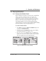
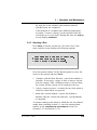
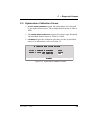
Specify the operating conditions:
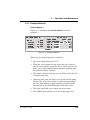
1. To specify the operating conditions for the fixed time
mode, press Menu to display the MENU OF SCREENS and
press 9 to display the EXTERNAL DEVICE INTERFACE screen
(see Figure 3-5).
EXTER N AL DEVIC E IN TER FA C E
FO LLO W ING A N EXTR A C TIO N :
U SE WA IT/C O N TIN U E TTL SIG N ALS
R O TATE TR AY TO PO SITIO N
H O LD TRAY (TTL=N O) FO R (M IN )
B TTL C ELL
TR AY TR AY
NO
NO
12
12
5
2
Figure 3-5. External Device Interface Screen:
Fixed Time Mode
2. Make sure the
set to NO.
USE WAIT/CONTINUE TTL SIGNALS
fields are
3. Follow the steps below to determine which tray position
the external device can access; this varies, depending on
the device design.
a. Check the method or schedule to see which tray
position is specified initially.
b. Make sure the tray is in position one. Press the Trays
button to release the tray, and then rotate it manually
until the external device can access the position
initially specified in the method or schedule.
3-14
Doc. 031672-01 4/2000
3 • Operation and Maintenance
c. Check to see which tray position is now in the home
position. Move the cursor to the ROTATE TRAY TO
POSITION field for the tray(s) to be accessed by the
external device and enter this number. Press Enter or a
cursor arrow button.
4. Move the cursor to the HOLD TRAY FOR field and enter the
number of minutes that the tray remains immobile. Be
sure to allow enough time for the external device to
perform its function and then move clear of the trays
before the ASE 300 goes on to the next extraction. Press
Enter or a cursor arrow button.
If the specified time is too short, the ASE 300 may attempt
to move a tray while it is being accessed by the external
device.
5. This completes the setup for operation in the fixed time
mode.
Doc. 031672-01 4/2000
3-15
ASE 300 Operator’s Manual
External Device Operation: TTL Mode
In the TTL mode, wait/continue TTL signals are used to
control rotation of the bottle tray and/or cell tray. After each
extraction, the ASE 300 sends a TTL output signal to the
external device and then waits for the device to send a TTL
signal. When the ASE 300 receives the TTL signal sent by
the device, it goes on to the next extraction in the method or
schedule.
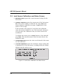
Specify the operating conditions:
1. To specify the operating conditions for the TTL mode,
press Menu to display the MENU OF SCREENS and press 9
to display the EXTERNAL DEVICE INTERFACE screen (see
Figure 3-6).
EXTER N AL DEVIC E IN TER FA C E
FO LLO W ING A N EXTR A C TIO N :
U SE WA IT/C O N TIN U E TTL SIG N ALS
R O TATE TR AY TO PO SITIO N
H O LD TRAY (TTL=N O) FO R (M IN )
B TTL C ELL
TR AY TR AY
YES YES
12
12
0
0
Figure 3-6. External Device Interface Screen: TTL Mode
2. Move the cursor to the USE WAIT/CONTINUE TTL SIGNALS
field for the tray(s) to be accessed by the external device
and select YES. Press Enter or a cursor arrow button.
3. Follow the steps below to determine which tray position
the external device can access; this varies, depending on
the device design.
a. Check the method or schedule to see which tray
position is specified initially.
3-16
Doc. 031672-01 4/2000
3 • Operation and Maintenance
b. Make sure the tray is in position one. Press the Trays
button to release the tray, and then rotate it manually
until the external device can access the position
initially specified in the method or schedule.
c. Check to see which tray position is now in the home
position. Move the cursor to the ROTATE TRAY TO
POSITION field for the tray(s) to be accessed by the
external device and enter this number. (Do not enter
zero; this disables operation of the external device
interface feature.) Press Enter or a cursor arrow button.
4. Make sure zero is entered in the HOLD TRAY FOR fields;
this disables operation in the fixed time mode. Go on to
the next section to make the TTL connections.
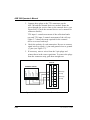
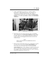
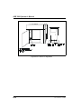
Make the TTL connections:
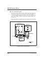
1. The TTL/relay connector strip is located on the CPU card,
behind the upper door (see Figure B-0). To open the door,
pull on the tab located to the right of the main power
actuator (see Figure 2-2).
Each 2-pin connector on the strip includes a signal pin (+)
and a ground (-) pin. The ASE 300 Ship Kit includes
twisted pairs of wires (P/N 043598) and two 2-pin
connector plugs (P/N 921019).
2. Attach a 2-pin connector plug to both ends of each pair of
wires to be connected. Strip the ends of the wires, insert
into the plug, and use a screwdriver to tighten the locking
screw. The signal wire goes on the top of each plug; the
ground wire goes on the bottom of the plug.
Doc. 031672-01 4/2000
3-17
ASE 300 Operator’s Manual
3. Connect these plugs to the TTL connectors on the
ASE 300 and the external device as needed. Route the
wires through the service chase to the external device (see
Figure B-0). (Check the external device user’s manual for
connector details.)
TTL input 1 controls movement of the collection bottle
tray and TTL input 2 controls movement of the cell tray.
Figure 3-7 shows the setup required for the external
device to access both trays.
4. Check the polarity of each connection. Be sure to connect
signal wires to signal (+) pins and ground wires to ground
(-) pins (see Figure 3-7).
5. If necessary, remove wires from the 2-pin plugs and
reinsert them in the correct positions. To remove the plugs
from the connector strip, pull them straight out.
ASE 300
R LY -1
O UT
EXTERN AL DEVIC E
TTL 2 O U T
GND
TTL 2 IN
GND
TTL 1 O U T
GND
TTL 1 IN
GND
R LY -2
O UT
+ T TL-1
- O UT
B ottle Tray
+ TTL-2
- O UT
C ell Tray
+ TTL-1
- IN
B ottle Tray
+ TTL-2
- IN
C ell Tray
+ TTL-3
- IN
TTL-4
IN
+
-
*Inactive
Figure 3-7. TTL Connections to an External Device
3-18
Doc. 031672-01 4/2000
3 • Operation and Maintenance
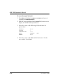
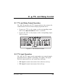
6. Press Menu to display the MENU OF SCREENS and press 8
to display the TIME FUNCTION IN screen (see Figure 3-8).
77/
77/
77/
77/
77/
77/
7,0( )81&7,21 ,1
,1387 02'( 1250$/ 38/6(
287387 02'( 1250$/ ('*( '85$7,21 ,1 %77/ &217 77/ 287 %77/
,1 &(// &217 77/ 287 &(//
,1 8186('
5/< 287 8186(' ,1 8186('
5/< 287 8186(' 3URPSW
Figure 3-8. Time Function In Screen
7. Move the cursor to the TTL INPUT MODE field and select
the mode that matches the signal type output by the
external device. (Check the external device user’s manual
for the signal type.) Press Enter or a cursor arrow button.
NOTE
The ASE 300 TTL inputs respond to four types of
device output signals; see Appendix E for details.
8. When each extraction is complete and the bottle is in
position for processing, the ASE 300 sends an output
signal to the external device. Move the cursor to the TTL
OUTPUT MODE field and specify the mode for this TTL
signal. Press Enter or a cursor arrow button.
9. Move the cursor to the DURATION field and specify the
TTL output pulse duration. (Check the external device
user’s manual for the signal duration values.) If no value
is entered, the default setting (100 milliseconds) remains
in effect. Press Enter or a cursor arrow button.
10. Go on to the next section to test the system configuration.
Doc. 031672-01 4/2000
3-19
ASE 300 Operator’s Manual
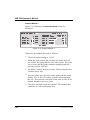
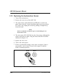
Test the system configuration:
1. Press Menu to display the MENU OF SCREENS and press 8
to display the TIME FUNCTION IN screen.
2. To verify the setup for the collection bottle tray, move the
cursor to the TTL OUT 1 BTTL field on the TIME FUNCTION IN
screen (see Figure 3-9). Select 1 and then press Enter or a
cursor arrow button. The external device should respond
when it receives the TTL signal.
77/
77/
77/
77/
77/
77/
7,0( )81&7,21 ,1
,1387 02'( 1250$/ 38/6(
287387 02'( 1250$/ ('*( '85$7,21 ,1 %77/ &217 77/ 287 %77/
,1 &(// &217 77/ 287 &(//
,1 8186('
5/< 287 8186(' ,1 8186('
5/< 287 8186(' 3URPSW
Figure 3-9. Time Function In Screen: Testing TTL Mode
3. To verify the setup for the cell tray, move the cursor to
the TTL OUT 2 CELL field on the TIME FUNCTION IN screen
(see Figure 3-9). Select 1 and then press Enter or a cursor
arrow button. The external device should respond when it
receives the TTL signal.
4. If the external device fails to respond to a TTL signal, do
the following:
Check that the TTL connections are correctly made.
Check that the correct TTL input mode is selected.
Using a digital voltmeter, verify that the ASE 300 is
sending a +5 V signal.
5. This completes the setup for operation in the fixed time
mode.
3-20
Doc. 031672-01 4/2000
3 • Operation and Maintenance
3.2 Methods and Schedules
NOTE
The following sections describe how to create custom methods
and schedules from the ASE 300 front panel. To get started
quickly, without creating a new method, run the default method
(see Section 3.4.1). For instructions on how to use AutoASE
software to create methods and schedules, refer to the AutoASE
manual or online Help.
Each sample extraction occurs according to a predefined set of
operating parameters, or method. A method specifies the cell heating
time, oven temperature, cell pressure, etc. The ASE 300 can store up
to 24 methods.
When running a series of extractions, you can run each sample using
the same method (method control), or customize the series by
defining a schedule of runs (schedule control). A schedule specifies
the method to run on each sample in the schedule, the sample cell
assigned to each collection bottle, and the rinse status after each
sample run. The ASE 300 can store up to 24 schedules.
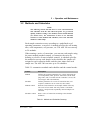
Table 3-1 summarizes methods and schedules and the control modes.
Feature
Description
Method
Defines the operating parameters for a single extraction run
(oven temperature, time, pressure, amount of solvent flush,
purge time, and, if an ASE Solvent Controller is in use, the
solvent types and concentrations).
Schedule
Defines parameters for a series of extraction runs (cell
sequence, method to run on each cell, rinse status).
Method control
Runs the same method on each sample loaded in the tray.
The series of runs starts with cell position 1 and bottle
position 1 and proceeds sequentially until all samples are
extracted.
Schedule control
Runs a series of extractions according to the schedule
definition.
Table 3-1. Methods and Schedules Summary
Doc. 031672-01 4/2000
3-21
ASE 300 Operator’s Manual
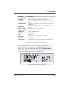
3.2.1 Creating Methods
Table 3-2 describes each method parameter. Refer to
Section 3.2.2 for example methods and Section 3.3 for
method development guidelines.
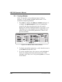
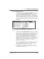
1. Press Menu to display the MENU OF SCREENS and press 3
to display the METHOD EDITOR. If you are opening the
screen for the first time after power-up, the screen
displays the default method parameters (see Figure 3-10).
Thereafter, the screen displays the last method that was
edited (if any) or the default parameters (if there is no
previous method).
0(7+2' (',7 #
PLQ
+($7
PLQ
67$7,&
)/86+ YRO
385*( VHF
&<&/(6
6$9( 72
SVL
35(6685(
&
7(03(5$785(
62/ $ 27+(5
%
62/ % 27+(5
%
62/ & 27+(5
%
62/ ' 27+(5
%
3URPSW
Figure 3-10. Method Editor Screen (Default)
2. To display the default parameters, verify that the cursor is
in the EDIT# field and enter zero.
3. To create a method, move the cursor to each highlighted
field to be changed and enter the desired value. After
entering a new value, save it by pressing Enter or a cursor
arrow button.
3-22
Doc. 031672-01 4/2000
3 • Operation and Maintenance
Parameter
Function
Value Range
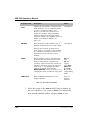
HEAT
Amount of time allowed for the sample to
reach thermal equilibrium. The duration of the
initial heat-up step depends on the method’s
temperature set point.
Set the set point to 0 only when the heat-up
period is not required to achieve complete
recovery of analytes.
5 to 9 min
Set Point (°C)
0 (off)
40-100
101-125
126-150
151-175
176-200
Heat-up Time (Minutes)
0
5
6
7
8
9
STATIC
Static solvent extraction time.
0 to 99 min
(default=5)
FLUSH%
Amount of solvent to flush through the cell
following the static heating step, expressed as
a percentage of the cell volume. For example,
if FLUSH=50%, 17 mL is flushed through a
34 mL cell, 33 mL is flushed through a
66 mL cell, and so on.
0 to 150% vol
in 5%
increments
(default=60)
PURGE
Amount of time nitrogen gas purges the cell.
60 to 900 sec
(default=100)
CYCLES
Number of times to perform the static heating
and flushing steps. When more than one cycle
is specified, the flush % volume is divided
among the cycles (see Example Method 1 on
page 3-27).
1 to 5
(default=1)
TEMPERATURE
Temperature at which to heat the cell. The
temperature also determines the duration of
the initial heat-up step (see page 3-25).
0, 40 to
200 °C
(0=off,
default=100)
Table 3-2. Method Editor Parameters
Doc. 031672-01 4/2000
3-23
ASE 300 Operator’s Manual
Parameter
Function
Value Range
PRESSURE
Amount of fluid pressure in the cell during
extraction. The pressure is maintained by the
pump.
1500 psi
(fixed)
10.34 MPa
102.1 atm
103.4 bar
SOL
SOL
SOL
SOL
The solvent type and concentration used for
the extraction. Unless an ASE Solvent
Controller is in use, this information is for
report purposes only and these fields may be
left blank.
5 to 100% in
5% increments
(default=100%
of solvent A);
solvent types
are listed on
page 3-25
A
B
C
D
Table 3-2. Method Editor Parameters (continued)
4. After entering the desired parameters, move the cursor to
the SAVE TO field. Enter a new (unused) method number,
or press Select ∆ to display the next unused method
number. Press Enter to save the method.
NOTE
To restore the default method parameters, move the
cursor to the EDIT# field and press Delete.
When the cursor is in the SAVE TO field, pressing Select ∆
cycles through the available method numbers. For
example, if methods 1 and 3 already exist, pressing
Select ∆ displays 2, the next unused number. Pressing
Select ∆ again displays 4, the next unused number. Press
Enter to save the method under the desired number.
3-24
Doc. 031672-01 4/2000
3 • Operation and Maintenance
Entering Solvent Types and Percentages
The METHOD EDITOR screen lists some of the most common
solvents for extractions. From the list, select the type(s) and
percentage of solvent(s) used in each method. If the solvent is
not listed, select OTHER.
Do not use solvents with an autoignition point of 40 to
200 °C. If you have a question about solvent suitability,
contact Dionex.
When an ASE Solvent Controller is in operation, these
selections determine the solvent type and amount delivered
by the Solvent Controller to the ASE 300. If the Solvent
Controller is not present and configured, this information has
no effect on the extraction.
To select a solvent type:
1. Move the cursor to the SOL A field and press Select ∆ or
Select ∇ to scroll through the list of solvents. The
following solvents are listed:
Acetone
Acetonitrile
Chloroform
Ethanol
Hexane
iso-Octane
iso-Propanol
Methanol
MeCl2
Pet Ether
PERC
THF
Toluene
Water
Water/Acid
Other
2. After selecting the type, press the right cursor arrow to go
to the % field and enter the percent concentration. If you
enter 100% in this field, the percentages for the other
three solvents are reset to zero.
3. If the solvent is a mixture of two or more types, enter the
other solvent types and percentages in the SOL B, SOL C ,
and/or SOL D fields. Make sure the total for all solvents is
equal to 100%.
Doc. 031672-01 4/2000
3-25
ASE 300 Operator’s Manual
Editing Methods
After creating a method, you can modify it by changing
parameter values. Either save the changes to the existing
method number, or save the altered method to a new method
number and preserve the original method.
1. Open the METHOD EDITOR screen. In the EDIT# field, enter
the number of the method to be edited (1-24), or press
Select ∆ to scroll through the numbers of previously
stored methods.
To display the default method parameters, enter zero.
2. After selecting the method number, press Enter. The
method’s defined parameters appear.
3. To change a parameter value, move the cursor to the field
and enter the new value. This deletes the previous value.
Table 3-2 lists the values allowed for each parameter.
4. When changes are complete, move the cursor to the SAVE
TO field. Press Enter to save the changes to the current
method number, or select a new method number and press
Enter.
3-26
Doc. 031672-01 4/2000
3 • Operation and Maintenance
3.2.2 Example Methods
Example Method 1
Figure 3-11 illustrates the
Example 1.
0(7+2' (',7 #
+($7
67$7,&
)/86+ %
385*(
&<&/(6
PLQ
PLQ
YRO
VHF
METHOD EDITOR
screen for
6$9( 72 35(6685(
SVL
7(03(5$785(
&
62/ $ 0HWKDQRO
%
62/ % 2WKHU
%
62/ & 2WKHU
%
%
62/ ' 2WKHU
3URPSW
Figure 3-11. Example Method 1
When run, the method proceeds as follows:
•
The oven begins heating to 75 °C.
•
When the oven reaches the set point, the cell is moved
into the oven and the pump fills the cell with solvent. The
static valve closes and the pump continues pumping until
the pressure reaches 1500 psi.
•
The initial 5-minute heat step occurs, followed by the first
5-minute static step.
•
After the static step, the static valve opens and the pump
flushes 13% of the cell volume of fresh solvent through
the cell. This amount is approximately one-third of the
total of 40% to be flushed through in the three cycles.
•
The static and flush cycles repeat two more times.
•
The method then continues to a 90-second purge step.
Doc. 031672-01 4/2000
3-27
ASE 300 Operator’s Manual
To create Example Method 1:
1. Press Menu to display the MENU OF SCREENS and press 3
to display the METHOD EDITOR.
2. With the cursor positioned in the EDIT# field, enter zero to
display the default method parameters.
3. Move the cursor to the following fields and enter the
given values:
FLUSH %
CYCLES
TEMPERATURE
SOL A
PURGE
40 vol
3
75 °C
Methanol
90 sec
100%
4. Move the cursor to the SAVE TO field and enter 3 for the
new method. Press Enter.
3-28
Doc. 031672-01 4/2000
3 • Operation and Maintenance
Example Method 2
Figure 3-12 illustrates the
Example 2.
0(7+2' (',7 #
+($7
67$7,&
)/86+ %
385*(
&<&/(6
PLQ
PLQ
YRO
VHF
METHOD EDITOR
screen for
6$9( 72 35(6685(
SVL
7(03(5$785(
&
62/ $ $FHWRQH
%
62/ % +H[DQH
%
62/ & 2WKHU
%
%
62/ ' 2WKHU
3URPSW
Figure 3-12. Example Method 2
When run, the method proceeds as follows:
•
The oven begins heating to 125 °C.
•
When the oven reaches the set point, the cell is moved
into the oven and the pump fills the cell with solvent. The
static valve closes and the pump continues pumping until
the pressure reaches 1500 psi.
•
An initial 6-minute heat step occurs, followed by a
10-minute static step.
•
After the static step, the static valve opens and the pump
flushes 70% of the cell volume of fresh solvent through
the cell.
•
The method then continues to a 60-second purge step.
Doc. 031672-01 4/2000
3-29
ASE 300 Operator’s Manual
Example Method 3
Figure 3-13 illustrates the
Example 3.
0(7+2' (',7 #
+($7
67$7,&
)/86+
385*(
&<&/(6
PLQ
PLQ
YRO
VHF
METHOD EDITOR
screen for
6$9( 72 35(6685(
SVL
7(03(5$785(
&
62/ $ $FHWRQH
%
62/ % 0H&O
%
62/ & 2WKHU
%
%
62/ ' 2WKHU
3URPSW
Figure 3-13. Example Method 3
When run, the method proceeds as follows:
3-30
•
The oven begins heating to 150 °C.
•
When the oven reaches the set point, the bottle and cell
are loaded. The pump fills the cell with solvent. The static
valve closes and the pump continues pumping until the
pressure reaches 1500 psi.
•
An initial 7-minute heat step occurs, followed by the first
5-minute static step.
•
After the static step, the static valve opens and the pump
flushes 25% of the cell volume of fresh solvent through
the cell. This amount is one-half of the total of 50% to be
flushed through in the two cycles.
•
The static and flush steps are repeated. The method then
continues to a 60-second purge step.
Doc. 031672-01 4/2000
3 • Operation and Maintenance
3.2.3 Creating Schedules
1. Press Menu to display the MENU OF SCREENS and press 4
to display the SCHEDULE EDITOR. When the screen is
opened for the first time after power-up, it displays the
default schedule parameters (see Figure 3-14). Thereafter,
the screen displays either the last schedule that was edited
(if any) or the default parameters (if there is no previous
schedule).
SCHEDULE EDIT #
1
RINSE
BTTL# CELL# M ETHOD#
O FF
1
1
2
2
O FF
3
O FF
3
4
4
O FF
5
5
O FF
Prom pt
SAVE TO
SAM PLE ID
Figure 3-14. Schedule Editor Screen (Default)
Each line in the SCHEDULE EDITOR represents one sample
extraction run. The maximum runs per schedule is 12. A
bottle number (1 through 12) is permanently assigned to
each line in the SCHEDULE EDITOR. Corresponding cell
numbers are preassigned to each bottle, but number
assignments are not permanent; you can change the cell
number sequence, skip cell numbers, or use the same cell
number multiple times. Bottle number assignments,
however, are permanent.
To scroll through the schedule, press the down arrow
button repeatedly. When the cursor reaches the bottom
line on the screen, the next line scrolls up.
2. For each line in a schedule, enter the desired schedule
information (see Table 3-3).
Doc. 031672-01 4/2000
3-31
ASE 300 Operator’s Manual
Schedule Field
Description
Values
CELL
Initially, the cell numbers correspond to the
bottle numbers (cell 1 is assigned to bottle
1, cell 2 is assigned to bottle 2, etc.).
However, you can enter a different cell
number. For example, when performing
multiple extractions on the same sample,
assign one sample cell to multiple (up to 12)
bottles (see Example Schedule 3 on
page 3-35).
1 through 12
METHOD
Enter the number of the method to run. A
different method can be run on each sample.
1 through 24
Because the oven heats up faster than it
cools down, it is advisable to enter methods
in a schedule from coolest to hottest. This
minimizes the oven wait time between
methods.
RINSE
SAMPLE ID
Specify whether a rinse is performed after
each extraction and which solvent is used.
When an ASE Solvent Controller is in
operation, select ON if the last solvent was
a mixture; otherwise, specify the solvent in
bottle A, B, C, or D. Initially, this field
contains the default value from the
MODULE SETUP screen (see Section 3.1.7).
Changing this field overrides the setup value.
Enter an identification number for the
sample (optional).
OFF=no
rinse,
ON=last
solvent
used; ON A,
ON B, ON
C, and ON
D=solvent in
corresponding
bottle
Up to 10
numeric
characters
Table 3-3. Schedule Parameters
3. Move the cursor to the SAVE TO field. Enter a number for
the new schedule (1-24), or press Select ∆ to display the
next unused schedule number and press Enter to save.
3-32
Doc. 031672-01 4/2000
3 • Operation and Maintenance
3.2.4 Example Schedules
Example Schedule 1
Run a different method every six extractions. Do not rinse
between extractions.
Bottle#
1
2
3
4
5
6
7
8
9
10
11
12
Doc. 031672-01 4/2000
Cell#
1
2
3
4
5
6
7
8
9
10
11
12
Method#
1
1
1
1
1
1
2
2
2
2
2
2
Rinse
OFF
OFF
OFF
OFF
OFF
OFF
OFF
OFF
OFF
OFF
OFF
OFF
Sample ID
3-33
ASE 300 Operator’s Manual
To create Example Schedule 1:
1. Press Menu to display the MENU OF SCREENS and 5 to
display the MODULE SETUP screen.
2. Verify that the METHOD RINSE field is OFF. If necessary,
move the cursor to the field and press Select ∆ to toggle
to OFF. Press Enter.
3. Verify that the MODE field is LOCAL. If necessary, move
the cursor to the field and press Select ∆ to toggle to
LOCAL. Press Enter.
4. Press Menu to display the MENU OF SCREENS and 4 to
display the SCHEDULE EDITOR .
5. With the cursor positioned in the EDIT# field, enter zero to
display the default schedule parameters (see Figure 3-14).
6. In this schedule, the method number is the only parameter
that needs to be entered because all others remain at their
default values. Move the cursor to the METHOD# field and
enter 1 for lines 1-6 in the schedule. Enter 2 for lines
7-12.
7. Move the cursor to the SAVE TO field and enter a number
for the new schedule. Press Enter.
3-34
Doc. 031672-01 4/2000
3 • Operation and Maintenance
Example Schedule 2
Run a different method every six extractions. Run three
extractions on the last cell. Rinse between extractions.
Bottle#
1
2
3
4
5
6
7
8
9
10
11
12
Doc. 031672-01 4/2000
Cell#
1
2
3
4
5
6
7
8
9
10
10
10
Method#
1
1
1
1
1
1
2
2
2
2
2
2
Rinse
ON
ON
ON
ON
ON
ON
ON
ON
ON
ON
ON
ON
Sample ID
1001
1002
1003
1004
1005
1006
1007
1008
1009
1010
1011
1012
3-35
ASE 300 Operator’s Manual
Example Schedule 3
Run three extractions on each cell. Run a different method
every six extractions. Rinse between samples.
Bottle#
1
2
3
4
5
6
7
8
9
10
11
12
3-36
Cell#
1
1
1
2
2
2
3
3
3
4
4
4
Method#
1
1
1
1
1
1
2
2
2
2
2
2
Rinse
OFF
OFF
ON
OFF
OFF
ON
OFF
OFF
ON
OFF
OFF
ON
Sample ID
1
2
3
4
Doc. 031672-01 4/2000
3 • Operation and Maintenance
3.3 Method Development Guidelines
Follow the procedure below when developing a method for a new
sample type:
1. Select a solvent(s) (see Section 3.1.1).
2. Prepare the sample (see Section 4.).
3. Select a cell size (see Section 3.1.4).
4. Create a new method with default operating parameters. To do
this, go to the METHOD EDITOR screen, position the cursor in the
EDIT# field, and enter zero to display the default parameters.
Move the cursor to the SAVE TO field and select a new method
number (2, for example). Press Enter to save the method.
5. Create a schedule that extracts the same sample three times into
separate bottles (see the example in Figure 3-15). Specify the
method created in Step 4 for each extraction.
2
SCHEDULE EDIT #
RINSE
BTTL# CELL# M ETHOD#
2
O FF
1
1
1
2
2
O FF
O FF
1
3
2
4
O FF
5
O FF
Prom pt
SAVE TO 2
SAM PLE ID
Figure 3-15. Example Schedule for Method Development
6. Run the schedule and analyze the extracts.
7. If target analytes are present in bottle 2 or 3, make the following
adjustments (one at a time) to the method:
a. Raise the temperature. In general, raising the temperature
increases the efficiency of the extraction process. However,
because compounds can degrade at high temperatures, it is
advisable to keep the temperature below the maximum
allowed (200 °C). If oxidation is a concern, degas the solvent
before use.
Doc. 031672-01 4/2000
3-37
ASE 300 Operator’s Manual
b. Run two static/flush cycles. Extending the static time
enhances diffusion of the analytes into the extraction fluid.
Separating the static time into two cycles, rather than using
one longer cycle, allows the introduction of fresh solvent
midway through. The fresh solvent helps maintain a favorable
solvent/sample equilibrium for samples that are heavily
loaded or otherwise difficult to extract.
c. Increase the flush volume to allow more solvent to pass
through the sample. The flush volume can be up to 150% of
the cell volume.
NOTE
To prevent overfilling of the 100 mL cells, it may be
necessary to balance the number of static cycles and flush
volume.
8. After each adjustment, repeat the schedule and analyze the
extract. When target analytes no longer appear in the extract
from the second bottle, the method is complete for this sample
type.
9. If analytes still appear in the extract from the second bottle,
make the following adjustments (one at a time) to the method:
3-38
•
Run three static/flush cycles.
•
Raise the temperature again.
•
Extend the static time.
•
Select a different solvent.
Doc. 031672-01 4/2000
3 • Operation and Maintenance
3.4 Running Extractions
3.4.1 Running Under Method Control
Before running an extraction, you must create a method that
defines operating conditions for the run. Section 3.2.1
explains how to create methods from the ASE 300 front
panel. For instructions on creating methods with AutoASE
software, refer to the software manual or online Help.
The default method lets you get started running quickly,
without having to create any custom methods. Before running
the default method, assign a method number to it.
To number the default method:
1. Press Menu to display the MENU OF SCREENS and press 3
to display the METHOD EDITOR.
2. With the cursor in the EDIT# field, enter zero to display
the default parameters (see Figure 3-16).
3. Move the cursor to the SAVE TO field; press Select ∆ to
display the next unused method number and press Enter .
The new method can now be loaded and run.
0(7+2' (',7 #
+($7
67$7,&
)/86+ 385*( &<&/(6
PLQ
PLQ
YRO
VHF
6$9( 72
SVL
35(6685(
&
7(03(5$785(
62/ $ 27+(5
%
62/ % 27+(5
%
62/ & 27+(5
%
62/ ' 27+(5
%
3URPSW
Figure 3-16. Method Editor Screen (Default)
Doc. 031672-01 4/2000
3-39
ASE 300 Operator’s Manual
To load a method and start the run:
4. Press Menu to display the MENU OF SCREENS , and press
Enter (or 1 ) to display the LOAD METHOD OR SCHEDULE
screen (see Figure 3-17).
LO A D M ETH O D OR SC H EDU LE
N U M B ER
LO A D M ETHO D
1
B TTL
1
Prom pt
Figure 3-17. Load Method or Schedule Screen
5. Verify that METHOD appears in the LOAD field. If it does
not, press Select ∆ to toggle to METHOD.
6. By default, the method begins running at bottle 1. To start
the run at a different bottle, move the cursor to the BTTL
field and enter the desired number.
7. Move the cursor to the NUMBER field and enter the
number of the method. Press Enter or a cursor arrow. This
closes the LOAD METHOD OR SCHEDULE screen and opens
the CURRENT STATUS screen. The CURRENT STATUS screen
displays the method number, as well as the status of other
ASE 300 operating parameters (see Figure 3-18).
/2&$/
°
%77/
Figure 3-18. Current Status Screen
3-40
Doc. 031672-01 4/2000
3 • Operation and Maintenance
NOTE
The temperature set point is activated immediately
after the method is loaded (before you press Start). If
the current oven temperature is less than the set point,
the oven begins heating.
8. Press Start to begin the run. If the oven has not reached the
set point, there is a delay while the oven heats up or cools
down. During this time, the STATUS screen displays OVEN
WAIT.
When the oven is within 5 °C of the set point, the cell
and bottle trays rotate to the first positions and the
ASE 300 begins running the first sample. During Method
control, the ASE 300 runs samples sequentially until it
reaches an empty cell or bottle slot or, if the trays are full,
until all samples have been run and the trays are back at
positions 1. See Section 2.2 for details about the
extraction process.
During the run, the status of operating parameters is
updated on the CURRENT STATUS screen. After a set time
(the default is 20 minutes), and if no keypad buttons have
been pressed, an alternate status screen is displayed (see
Figure 3-19). To return to the CURRENT STATUS screen,
press any button on the front panel keypad.
B TTL
Figure 3-19. Alternate Status Screen
NOTE
To change the time delay for displaying the alternate
status screen, or to disable the screen, see Section B.3.
Doc. 031672-01 4/2000
3-41
ASE 300 Operator’s Manual
3.4.2 Running Under Schedule Control
1. Press Menu to display the MENU OF SCREENS , and press
Enter (or 1 ) to display the LOAD METHOD OR SCHEDULE
screen.
2. Press a Select button to toggle to
Figure 3-20).
LOAD SCHEDULE
(see
LO A D M ETH O D OR SC H EDU LE
LO A D SC H ED U LE
1
B TTL
N U M B ER
1
Prom pt
Figure 3-20. Load Method or Schedule Screen
3. By default, the schedule begins running at bottle 1. To
start the schedule at a different bottle, move the cursor to
the BTTL field and enter the desired number.
4. Move the cursor to the NUMBER field and enter the
number of the schedule to be run. Press Enter or a cursor
arrow. The LOAD METHOD OR SCHEDULE screen closes and
the CURRENT STATUS screen appears.
NOTE
The temperature set point is activated immediately
after the schedule is loaded (before you press Start).
If the oven temperature is below the set point, the oven
begins heating.
5. Press Start.
The ASE 300 begins the first run according to the
parameters in the first method in the schedule. When the
first extraction run is complete, the ASE 300 proceeds to
3-42
Doc. 031672-01 4/2000
3 • Operation and Maintenance
the next line in the schedule and continues until all
scheduled runs are completed.
If the methods in a schedule have different temperature
set points, it causes a delay(s) in the schedule while the
oven heats up or cools down. During this time, the STATUS
screen displays OVEN WAIT.
3.4.3 Aborting a Run
Press Abort to halt the current run. All valves close, flow
stops, and the screen displays the following options:
&RQWLQXH ZLWK WKH DERUW IXQFWLRQ
&DQFHO UHWXUQ WR SURFHVV
$ERUW DIWHU FXUUHQW PHWKRG
Press the numeric button for the desired option (or move the
cursor to the option) and press Enter.
1
Continue with the abort function—cancels the method or
schedule. If necessary, a purge is done to remove solvent
from the sample. Then, residual pressure is relieved from
the system and the current cell is returned to the tray.
2
Cancel: return to process—resumes the run at the point at
which the abort button was pressed.
3 Abort after current method—cancels the method or
schedule after the current run (and rinse, if programmed)
is completed.
To resume running at the bottle at which the run was aborted
(rather than restarting at bottle 1), enter the starting bottle
number on the LOAD METHOD OR SCHEDULE screen (see
Sections 3.4.1 and Section 3.4.2).
Doc. 031672-01 4/2000
3-43
ASE 300 Operator’s Manual
3.5 Post-Extraction Procedures
3.5.1 Cleaning the Cells
Cells are extremely hot after an extraction. Allow cells to
cool for at least 15 minutes before handling. Be especially
cautious with cells that have been heated over 50 °C.
After use, empty the cells and rinse the cell bodies and cell
caps with water or organic solvent.
•
Cell bodies (but not cell caps) can be cleaned in a
dishwasher or high temperature cleaning unit. Do not
exceed 400 °C when performing high temperature
cleaning.
•
For most applications, simply rinsing the end caps is
sufficient. If necessary, disassemble the end caps (see
Section 5.1) and sonicate or soak in solvent.
3.5.2 Processing Extracts
The composition of the extracts generated by the ASE 300 is
very close to that generated by Soxhlet and other standard
liquid extraction techniques when using the same solvent.
Therefore, you may use the same analytical method for the
ASE extracts that was employed for extracts obtained from
other techniques.
NOTE
An external device can be interfaced with the ASE 300
system to automatically process the sample extracts. See
Section 3.1.8 for details.
3-44
Doc. 031672-01 4/2000
3 • Operation and Maintenance
3.6 Routine Maintenance
This section describes routine maintenance procedures that may be
performed by the user. All other maintenance procedures must be
performed by Dionex personnel.
3.6.1 Daily Maintenance
•
Fill the solvent reservoir, if needed. Run a rinse cycle
after filling.
•
Empty the waste bottle, if needed.
•
Empty the rinse bottle.
•
Check the gases.
•
Check for leaks from the solvent reservoir, pump, valves,
and other components in the flow path (see Figure 3-21).
Wipe up liquids and tighten or replace leaking fittings
(see Section 5.2).
3.6.2 Periodic Maintenance
•
Replace the external O-rings (P/N 049457, pkg. of 50
Teflon O-rings; P/N 056325, pkg. of 50 Viton O-rings) in
the cell caps and rinse tubes approximately every 50 to 75
extractions. (Viton O-rings are for use in high temperature
applications, such as dioxins.)
•
Replace the PEEK seals (P/N 056777, pkg. of 10;
P/N 056776, pkg. of 50) inside the cell caps after
approximately every 50 to 75 extractions (see Section 5.1).
•
Verify that the two needles on the needle mechanism are
straight. See Section 5.7 for replacement instructions.
•
Replace the septum in the rinse bottle.
Doc. 031672-01 4/2000
3-45
ASE 300 Operator’s Manual
Left-Side Panel Door
Transducer
Relief Valve
Oven/AutoSeal Area
(under top-right cover)
AutoSeal Arm
Check Valve
Sam ple Cell or
Rinse Tube
Purge Valve
Pump
Solenoids
Pump
Needle M echanism
(on right-inside panel)
Static
Valve
Regulator
50 psi
To N 2
Supply
Prime
Valve
Tee
To Vent on
Rear Panel
To Vent on
Rear Panel
Solvent
Reservoir
Waste
Bottle
Collection
Bottle
Solvent Reservoir
Com partm ent
Gas Lines
Solvent Lines
Figure 3-21. Solvent Flow Schematic
3-46
Doc. 031672-01 4/2000
3 • Operation and Maintenance
3.7 Shutdown
•
If the solvent is 100% organic, simply turn off the power for
overnight shutdown.
•
If the solvent contains acids or other strong additives, rinse the
system with a 100% organic solvent or with distilled water
before overnight shutdown.
•
For longer shutdowns, also turn off the gas and compressed air
supplies.
•
Before shipping the ASE 300, empty all solvent bottles,
reconnect the bottles to the system, and run one or more rinse
cycles to remove solvent from the lines.
NOTE
If there is no input to the ASE 300 for four hours (no control
panel buttons are pressed and no commands are received from
AutoASE software), the oven is automatically shut off.
Doc. 031672-01 4/2000
3-47
ASE 300 Operator’s Manual
3-48
Doc. 031672-01 4/2000
4 • Troubleshooting
This chapter is a guide to troubleshooting problems that may occur
while operating the ASE 300 Accelerated Solvent Extractor. Turn to
the section that best describes the operating problem. There, possible
causes of the problem are listed in order of probability, along with
the recommended courses of action.
If the screen displays an error message, check the list of error
messages for possible causes.
If you are unable to eliminate a problem, contact Dionex. In the
U.S., call 1-800-346-6390 and select the Technical Support option.
Outside the U.S., call the nearest Dionex office.
4.1 Error Messages
When an error occurs, an error message is displayed on the screen.
The message remains until you press a key to clear it, or until it is
replaced by another error message. Each message is identified by a
number in the lower-right corner of the screen.
The ERROR LOG screen lists all errors that occurred during a given
run. The screen also identifies the cell and bottle number in use
when an error occurred. See Section C.3 for details.
•
212
You forgot to save your method after editing it. Press
ENTER again to abandon it permanently or press any
other key to finish editing this method.
Cause: After editing a method, but before saving the
editing changes, you tried to load a different method.
Action: If you do not want to save the editing changes,
press Enter to retain the method in its previously saved
version.
Action: If you want to continue editing the method, press
any key. When you finish editing, move the cursor to the
Doc. 031672-01 4/2000
4-1
ASE 300 Operator’s Manual
field and press Enter to save the changes to the
current method number. To save the changes to a different
number, move the cursor to the SAVE TO field and enter a
new (unused) method number, or press Select ∆ to display
the next unused method number. Press Enter to save the
method.
SAVE TO
•
224
You forgot to save your method after editing it. Press
MENU again to abandon it permanently or press any
key other than ENTER to finish editing the method.
Cause: After editing a method, but before saving the
editing changes, you pressed the Menu button to exit the
METHOD EDITOR screen.
Action: If you do not want to save the editing changes,
press Menu again to retain the method in its previously
saved version.
Action: If you want to continue editing the method, press
any key. When you finish editing, move the cursor to the
SAVE TO field and press Enter to save the changes to the
current method number. To save the changes to a different
number, move the cursor to the SAVE TO field and enter a
new (unused) method number, or press Select ∆ to display
the next unused method number. Press Enter to save the
method.
•
248
The instrument is in REMOTE mode. Put the instrument in LOCAL mode to use this function.
Cause: When the ASE 300 is in REMOTE mode, some
functions are disabled and only three keypad buttons are
functional: Trays, Rinse, and Abort.
Action: Press Menu to display the MENU OF SCREENS and
press 5 to display the MODULE SETUP screen. Move the
cursor to the MODE field and press a Select button to
toggle the field to LOCAL (see Figure 3-4). Press Enter or
a cursor arrow button.
4-2
Doc. 031672-01 4/2000
4 • Troubleshooting
•
300
You pressed an incorrect key for this entry.
Cause: You pressed an invalid key, unexpected for this
entry.
Action: Enter an acceptable value. Table 3-2 lists the
values allowed for method parameters. Table 3-3 lists the
values allowed for schedule parameters.
•
301
Detected an error in the database.
Cause: The memory in which the database is stored has
become corrupted.
Action: Contact Dionex for assistance.
•
302
There is an ASE function in progress. Please wait for
function to complete.
Cause: The function in progress must occur by itself, or
else cannot occur at the same time as the function you
attempted to initiate.
Action: Wait until the function in progress is completed
before pressing a front panel button or making an entry on
the screen.
•
303
A valid schedule has not been selected.
Cause: You selected a nonexistent schedule number to run.
Action: Enter a valid schedule number in the NUMBER
field of the LOAD METHOD OR SCHEDULE screen.
Doc. 031672-01 4/2000
4-3
ASE 300 Operator’s Manual
•
304
There is an error in the composition of the schedule
line.
Cause: The line references a nonexistent method or a
method that contains an error. If the error is in line 1 of
the schedule, this message appears when the schedule is
loaded. Otherwise, the schedule begins running, but stops
when it reaches the schedule line with the error.
Action: Check all lines in the schedule. Enter a valid
method number and/or correct the error in the method.
Table 3-2 lists the values allowed for method parameters.
Table 3-3 lists the values allowed for schedule parameters
•
305
The oven will not come up to temperature.
Cause: The heater cable connection to the power supply
is loose, or there is a problem with a heater component.
Action: Open the upper door. The power supply is on the
left. Check the heater cable plugged into the 4-pin
connector on the power supply; if the cable is plugged in
firmly, the problem is with an internal heater component.
Contact Dionex for assistance.
•
306
Time-out on flush portion of the method.
Cause: The pump was unable to deliver the specified
flush volume before the time-out expired; the cell or lines
may be plugged.
Action: Rinse the system to ensure that the pump and
valves are clear. If the rinse runs successfully, the cell
may be plugged. Clean or replace the stainless steel cell
frit (see Section 5.1) and replace the cellulose or
glass-fiber filter (see Section 3.1.4). Then, mix the sample
with a dispersing agent (see Section 3.1.3) and run the
extraction again.
If the rinse is not successful, the solvent lines may be
plugged. Contact Dionex for assistance.
4-4
Doc. 031672-01 4/2000
4 • Troubleshooting
•
307
Time-out condition in loading a collection bottle.
Cause: A collection bottle was not in the specified
position of the schedule.
Action: Before running a schedule, check that all bottles
are in place.
•
308
The collection bottle is full.
Cause: The collection bottle is full, or the sensor failed to
detect it.
Action: Empty the bottle, if needed, and check that the
bottle label is not blocking the area read by the sensor.
See Figure 3-0 for acceptable bottle label locations. If the
error message reappears, contact Dionex for assistance.
•
309
Error time-out condition in loading a cell.
Cause: A cell was not in the specified position of the
schedule.
Action: Before beginning a schedule, check that all cells
are in place.
•
310
Error time-out condition in unloading a cell.
Cause: A cell was not in the specified position of the
schedule.
Action: Before beginning a schedule, check that all cells
are in place.
•
311
The selected method is not valid or a method has not
been selected.
Cause: The selected method is incomplete, or a method
was not selected.
Action: If you have not done so already, select a method.
If the selected method is invalid, make sure there are no
missing steps.
Doc. 031672-01 4/2000
4-5
ASE 300 Operator’s Manual
•
312
Solvent does not reach collection bottle or rinse bottle.
Cause: The safety time-out expired before the bottle
sensors detected any solvent in the bottle; the cell or lines
may be plugged.
Action: After the run, rinse the system to make sure that
the pump and valves are clear. If the rinse runs
successfully, the cell may be plugged. Clean or replace
the stainless steel cell frit (see Section 5.1) and replace
the cellulose or glass-fiber filter (see Section 3.1.4). Then,
mix the sample with a dispersing agent (see Section 3.1.3)
and run the extraction again.
If the rinse is not successful, the solvent lines may be
plugged. Contact Dionex for assistance.
•
313
A schedule or method run cannot start because of a
safety condition. Check incoming air or bottle tray.
Cause: Air or nitrogen pressures are low.
Action: Check regulator pressures (see Section B.2.5).
Check for air leaks (see Section 4.4).
•
314
The needle will not retract.
Cause: The needle mechanism is disabled.
Action: Check the air pressure. The air source should be
between 0.41 and 1.38 MPa (60 and 200 psi); 0.69 MPa
(100 psi) is recommended. Check the system air regulator
pressure (see Section B.2.5). Check the delivery of air to
the needle mechanism. Open the left-side panel door and
make sure nothing is blocking the needle mechanism.
4-6
Doc. 031672-01 4/2000
4 • Troubleshooting
•
315
Bottle tray will not home.
Cause: The tray is blocked or disabled, or the sensor is
out.
Action: Make sure nothing is physically blocking the tray.
Manually check the tray movement. If necessary, contact
Dionex for assistance.
•
316
WARNING: Rinse bottle is missing or full. Please empty
and replace rinse bottle. Press ENTER to continue.
Cause: The rinse bottle is not available for use, or is not
detected by the bottle sensors.
Action: Make sure the rinse bottle is present in the R1
position of the bottle tray. If the rinse bottle is full, empty
or replace it.
Action: Make sure the bottle label is not blocking the
area read by the bottle sensors. See Figure 3-0 for
acceptable locations for bottle labels. If the error message
reappears, contact Dionex for assistance.
•
317
Needle will not engage or a collection bottle is not
present.
Cause: A collection bottle was not in the specified
position of the schedule, or the movement of the needle
assembly to the tray is physically blocked.
Action: Before beginning a schedule, check that all
bottles are in place. Open the left-side panel door and
make sure nothing is blocking the needle mechanism.
•
318
Bottle will not go to position.
Cause: The bottle tray is incorrectly installed.
Action: Contact Dionex for assistance.
Doc. 031672-01 4/2000
4-7
ASE 300 Operator’s Manual
•
319
Collection bottle is missing.
Cause: No collection bottle is installed, or the sensors
cannot detect the bottle.
Action: Make sure a collection bottle is installed in the
correct position of the bottle tray.
Action: Make sure the bottle label is not blocking the
area read by the sensors. See Figure 3-0 for acceptable
locations for bottle labels. If the error message reappears,
contact Dionex for assistance.
•
320
Bottle tray motor logic error condition.
Cause: The bottle tray motor or sensor has malfunctioned.
Action: Contact Dionex for assistance.
•
321
Cell tray will not home.
Cause: The tray is blocked or disabled, or the sensor is
out.
Action: Make sure nothing is physically blocking the tray.
Manually check the tray movement. If necessary, contact
Dionex for assistance.
•
322
There are no rinse tubes.
Cause: The cell tray does not contain any rinse tubes.
Action: Install rinse tubes between positions 3 and 4 and
positions 9 and 10 of the cell tray.
•
323
Cell tray will not rotate to the correct position.
Cause: The tray is physically blocked, or the sensor is out
of position.
Action: Make sure nothing is physically blocking the tray.
Manually check the tray movement. If necessary, contact
Dionex for assistance.
4-8
Doc. 031672-01 4/2000
4 • Troubleshooting
•
324
Cell tray motor logic error condition.
Cause: The cell tray motor or sensor has malfunctioned.
Action: Contact Dionex for assistance.
•
325
The AutoSeal arm will not open.
Cause: The air supply is not reaching the arm.
Action: Check the air pressure. The air source should be
between 0.41 and 1.38 MPa (60 and 200 psi); 0.69 MPa
(100 psi) is recommended. Check the system air regulator
pressure (see Section B.2.5). Check for air leaks (see
Section 4.4).
•
326
There is a cell in the AutoSeal arm.
Cause: The cell was not returned to the tray.
Action: Remove the cell from the arm and place it in the
correct position in the tray.
•
327
The AutoSeal arm will not move to the tray.
Cause: The air supply is not reaching the arm.
Action: Check the air pressure. The air source should be
between 0.41 and 1.38 MPa (60 and 200 psi); 0.69 MPa
(100 psi) is recommended. Check the system air regulator
pressure (see Section B.2.5). Check for air leaks (see
Section 4.4).
Cause: The arm is hitting the cell tray.
Action: The arm is out of alignment. Contact Dionex for
assistance.
•
328
No cell present at this position.
Cause: No cell is installed, or the sensors cannot detect it.
Action: Make sure a cell is installed in the correct
position in the tray. If the sensors do not detect the
installed cell, contact Dionex for assistance.
Doc. 031672-01 4/2000
4-9
ASE 300 Operator’s Manual
•
329
The AutoSeal arm will not move to the oven.
Cause: The air supply is not reaching the arm.
Action: Check the air pressure. The air source should be
between 0.41 and 1.38 MPa (60 and 200 psi); 0.69 MPa
(100 psi) is recommended. Check the system air regulator
pressure (see Section B.2.5). Check for air leaks (see
Section 4.4).
•
331
The entered value for this parameter is not in range.
Please re-enter value.
Cause: The value is too high or too low for this parameter.
Action: Enter an acceptable value. Table 3-2 lists the
values allowed for method parameters. Table 3-3 lists the
values allowed for schedule parameters.
•
332
Cannot perform the rinse function because another
function is in progress.
Cause: The Rinse button functions only when the
ASE 300 is idle. (The LED on the left of the Start button
is lighted when the ASE 300 is idle.)
Action: Wait until the function in progress is completed
before pressing the Rinse button.
•
333
Cannot engage the tray motors at this time because
another function is in progress.
Cause: The tray can be engaged only when the ASE 300
is idle. (The LED on the left of the Start button is lighted
when the ASE 300 is idle.)
Action: Wait until the function in progress is completed,
or press the Abort button and select the desired option.
4-10
Doc. 031672-01 4/2000
4 • Troubleshooting
•
334
Cannot start a schedule or method run because another
function is in progress.
Cause: A schedule or method cannot begin while another
function is in progress.
Action: Wait until the function in progress is completed.
Or, press the Abort button, select the desired option, and
then start the schedule or method.
•
335
Cannot engage or disengage the tray motors because
either the bottle needle is in place or the AutoSeal arm
has a cell at the tray.
Cause: The bottle tray can be engaged or disengaged only
when the ASE 300 is idle. (The LED on the left of the
Start button is lighted when the ASE 300 is idle.)
Action: Wait until the ASE 300 is idle, or else press the
Abort button and select the desired option.
•
336
Cell pressure has exceeded maximum allowable
threshold. The pump has been turned off for safety
reasons.
Cause: A blockage in the system; the cell or lines may be
plugged, or the static or relief valves may have failed.
Action: Run a rinse cycle. If the rinse runs successfully,
the cell may be plugged. Clean or replace the stainless
steel cell frit (see Section 5.1) and replace the cellulose or
glass-fiber filter (see Section 3.1.4). Next, mix the sample
with a dispersing agent such as diatomaceous earth or
sand (see Section 3.1.3) and run the extraction again.
If the rinse is not successful, there may be a blockage in
the solvent lines, or the static or relief valve may need
replacing. Contact Dionex for assistance.
Doc. 031672-01 4/2000
4-11
ASE 300 Operator’s Manual
•
337
Possible problem with the Temperature RTD. It
appears to be shorted.
Cause: The temperature display is inconsistent with
normal operation.
Action: The RTD (Resistive Temperature Device) should
be replaced. Contact Dionex for assistance.
•
339
A process (schedule/method) in progress. Please wait
for completion of task.
Cause: The schedule or method must finish running
before a new function is initiated.
Action: Wait until the schedule or method finishes
running before pressing a front panel button or making an
entry on the screen. Or, cancel the process by pressing the
Abort button, and then initiate the new task .
•
341
Oven nitrogen pressure is low.
Cause: The nitrogen gas pressure applied to the oven
compression system during an extraction is less than the
approximately 1.03 MPa (150 psi) that is required.
Action: Check the compression oven gauge in the solvent
reservoir compartment (see Figure B-0 in Appendix B);
the gauge should read 150 psi. If it does not, adjust the
regulator knob for the gauge (see Figure B-6) until the
gauge reads 130 psi.
Action: Adjust the pressure regulator on the nitrogen
supply to 0.97 to 1.38 MPa (140 to 200 psi).
Action: If the nitrogen supply is low, replace it.
Action: If there is any drift in the electronics, they must
be recalibrated. Contact Dionex for assistance.
4-12
Doc. 031672-01 4/2000
4 • Troubleshooting
•
342
Solvent vapor threshold exceeded.
Cause: A leak in the cell.
Action: Tighten the cell caps (hand-tighten only). Check
for foreign material on the threads of the cap, seal
surface, and cell body. If necessary, replace the O-rings
(see Figure 3-2) and/or the PEEK seals (see Section 5.1).
Cause: Solvent was not completely removed from the cell
during the purge cycle (especially with 100 mL cells).
Action: Increase the purge time (see Section 3.2.1).
Cause: A leak in the system.
Action: Open the left-side panel door and visually inspect
the following for leaks (see Figure 4-3): pump check
valves, pump fittings, solvent line fittings, transducer
fittings, relief valve fittings, and static valve fittings.
Tighten or replace any leaking fittings (see Section 5.2).
•
343
Internal leak into pan threshold exceeded. Please
correct problem and press any key to continue.
Cause: There is a leak in the solvent flow path.
Action: Open the left-side panel door and visually inspect
the following for leaks (see Figure 4-3): pump check
valves, pump fittings, solvent line fittings, transducer
fittings, relief valve fittings, and static valve fittings.
Tighten or replace any leaking fittings (see Section 5.2).
•
344
Pump cavitation: Check solvent bottle for solvent.
There may be a leak or other pump-related problem.
Cause: The solvent reservoir is empty.
Action: Refill the solvent reservoir with a prepared
solvent.
Doc. 031672-01 4/2000
4-13
ASE 300 Operator’s Manual
Cause: A defective cell cap O-ring is allowing leakage.
Action: Replace the external O-rings (P/N 049457, pkg.
of 50 Teflon O-rings; P/N 056325, pkg. of 50 Viton
O-rings). Replace the O-rings approximately every 50 to
75 extractions, or when worn.
Cause: Air in the lines.
Action: Check all air lines.
•
345
System air pressure has dropped below a safe level.
Restore air pressure and press any key to continue.
Cause: The SYSTEM AIR PRESSURE is the pressure from
the compressed air source. This reading should be
approximately equal to the reading on the pressure gauge
labeled AIR behind the lower door (see Figure B-0 on
page B-14).
Action: Adjust the pressure regulator for the air supply to
50 psi.
Action: If the error message appears again, the electronics
may need to be recalibrated. Contact Dionex for
assistance.
•
346
Total solvent percentage should be equal to 100% to
run.
Cause: You attempted to run a method in which the total
for all solvents is less than 100%. This may be an older
method, written before the introduction of the ASE
Solvent Controller.
Action: Adjust the percentages in the method so that the
total for all solvents equals 100%, save the method, and
restart the run.
4-14
Doc. 031672-01 4/2000
4 • Troubleshooting
Cause: AutoASE downloaded a method in which the total
of the selected solvents does not equal 100%.
Action: Adjust the percentages in the method so that the
total for all solvents equals 100%, save the method, and
restart the run.
Cause: The total solvent percentage in the method equals
100%, but memory is corrupted.
Action: Contact Dionex for assistance.
•
347
The instrument is in REMOTE mode. Put the instrument in LOCAL mode to modify this entry.
Cause: In some cases, the ASE 300 must be in LOCAL
mode before you can enter a value on the screen or press
a Select button to toggle a field between parameters.
Action: Press Menu to display the MENU OF SCREENS and
press 5 to display the MODULE SETUP screen. Move the
cursor to the MODE field and press a Select button to
toggle the field to LOCAL (see Figure 3-4). Press Enter or
a cursor arrow button.
•
348
The instrument is in REMOTE mode. Put the instrument in LOCAL mode to use this function.
Cause: In some cases, the ASE 300 must be in LOCAL
mode before you can operate a particular feature.
Action: Press Menu to display the MENU OF SCREENS and
press 5 to display the MODULE SETUP screen. Move the
cursor to the MODE field and press a Select button to
toggle the field to LOCAL (see Figure 3-4). Press Enter or
a cursor arrow button.
Doc. 031672-01 4/2000
4-15
ASE 300 Operator’s Manual
•
349
You forgot to save your method after editing it. Press
ENTER again to abandon it permanently or press
any other key to finish editing this method.
Cause: You tried to load a new method before saving
changes to the method currently being edited.
Action: If you do not want to save the editing changes,
press Enter to abandon them and retain the method in its
previously saved version. If you want to continue editing
the method, press any key. When you finish editing, you
have two options:
To save the changes to the current method number, move
the cursor to the SAVE TO field and press Enter.
To save the changes to a different method number, move
the cursor to the SAVE TO field and enter a new (unused)
schedule number, or press Select ∆ to display the next
unused method number. Press Enter to save the method.
•
350
You forgot to save your method after editing it. Press
MENU again to abandon it permanently or press
any other key to continue editing the method.
Cause: You pressed Menu before saving changes to the
method currently being edited.
Action: If you do not want to save the editing changes,
press Menu again. This retains the method in its
previously saved version. If you want to continue editing
the method, press any key. When you finish editing, you
have two options:
To save the changes to the current method number, move
the cursor to the SAVE TO field and press Enter.
To save the changes to a different method number, move
the cursor to the SAVE TO field and enter a new (unused)
method number, or press Select ∆ to display the next
unused method number. Press Enter to save the method.
4-16
Doc. 031672-01 4/2000
4 • Troubleshooting
•
351
You forgot to save your schedule after editing it. Press
ENTER again to abandon it permanently or press
any other key to finish editing this schedule.
Cause: You tried to load a new schedule before saving
changes to the schedule currently being edited.
Action: If you do not want to save the editing changes,
press Enter. This retains the schedule in its previously
saved version. If you want to continue editing the
schedule, press any key. When you finish editing, you
have two options:
To save the changes to the current schedule number, move
the cursor to the SAVE TO field and press Enter.
To save the changes to a different schedule number, move
the cursor to the SAVE TO field and enter a new (unused)
schedule number, or press Select ∆ to display the next
unused schedule number. Press Enter to save the schedule.
•
352
You forgot to save your schedule after editing it. Press
MENU again to abandon it permanently or press
any other key to continue editing the schedule.
Cause: You pressed Menu before saving changes to the
schedule currently being edited.
Action: If you do not want to save the editing changes,
press Menu again to abandon them and retain the schedule
in its previously saved version. If you want to continue
editing the schedule, press any key. When you finish
editing, you have two options:
To save the changes to the current schedule number, move
the cursor to the SAVE TO field and press Enter.
To save the changes to a different schedule number, move
the cursor to the SAVE TO field and enter a new (unused)
schedule number, or press Select ∆ to display the next
unused schedule number. Press Enter to save the schedule.
Doc. 031672-01 4/2000
4-17
ASE 300 Operator’s Manual
•
353
Method cannot be saved if total solvent percentage is
not equal to 100%. Check solvent percentage for error.
Cause: You attempted to save a method in which the total
of selected solvents is less than or greater than 100%.
Action: Adjust the percentages so that the total for all
solvents equals 100% and then save the method.
•
354
Hydrocarbon sensor reading is low. Recalibrate
hydrocarbon baseline. Hydrocarbon sensor may need to
be replaced.
Cause: The hydrocarbon level is significantly lower than
expected.
Action: Calibrate the hydrocarbon sensor at the earliest
opportunity. Refer to Section 5.9 for calibration
instructions.
Action: If the error message reappears, replace the
hydrocarbon sensor. Refer to Section 5.10 for instructions
on how to install a new sensor.
•
355
WARNING ONLY: Hydrocarbon sensor reading is low.
Recalibrate hydrocarbon baseline, using diagnostic
screen.
Cause: The hydrocarbon level is lower than expected.
Action: Calibration of the hydrocarbon sensor is
recommended at this time, but is not required. If you do
not calibrate the sensor now, there is a risk that a
subsequent run may be aborted unexpectedly. Refer to
Section 5.9 for calibration instructions.
4-18
Doc. 031672-01 4/2000
4 • Troubleshooting
•
356
Time-out condition in rotating the collection bottle for
external interface.
Cause: A collection bottle was not in the specified
position before the time-out expired. The bottle tray is
physically blocked, or the electronics have malfunctioned.
Action: Turn off the power. Make sure nothing is
physically blocking the tray. Manually check the tray
movement. Turn on the power and resume operation.
Action: If the error message reappears, the electronics
have malfunctioned. Contact Dionex for assistance.
•
357
Conflicting entry: Either the bottle position is zero or
TTL is enabled.
Cause: To have an external device access sample from the
collection bottle tray, you must specify a non-zero tray
position and disable the TTL signals.
to display the
screen. If necessary, move
the cursor to the ROTATE BTTL TRAY TO POSITION field and
enter a new (non-zero) position. If necessary, move the
cursor to the USE WAIT/CONTINUE TTL SIGNALS field and
select NO. Press Enter or a cursor arrow button to save the
editing changes.
Action: Press
9
on the
MENU OF SCREENS
EXTERNAL DEVICE INTERFACE
•
358
Time-out condition in rotating the cell tray for external
interface.
Cause: A cell was not in the specified position before the
time-out expired. The cell tray is physically blocked, or
the electronics have malfunctioned.
Action: Turn off the power. Make sure nothing is
physically blocking the tray. Manually check the tray
movement. Turn on the power and resume operation.
Action: If the error message reappears, the electronics
have malfunctioned. Contact Dionex for assistance.
Doc. 031672-01 4/2000
4-19
ASE 300 Operator’s Manual
•
359
Conflicting entry: Either the cell position is zero or
TTL is enabled.
Cause: To have an external device access the cell tray,
you must specify a non-zero tray position and disable the
TTL signals.
Action: Press
to display the
screen. If necessary, move
the cursor to the ROTATE TRAY TO POSITION field and enter a
new (non-zero) position. If necessary, move the cursor to
the USE WAIT/CONTINUE TTL SIGNALS field and select NO.
Press Enter or a cursor arrow button to save the changes.
9
on the
MENU OF SCREENS
EXTERNAL DEVICE INTERFACE
•
361
Leak sensor needs recalibration. Go to Leak Sensor
Status and Calibration screen to perform recalibration
operation.
Cause: The leak sensor is out of calibration.
Action: See Section C.5 for calibration instructions.
•
362
Invalid leak sensor reading. May be open or short
circuit, or bad sensor. See Leak Sensor Status and
Calibration screen for more information.
Cause: There is an open or short circuit, or the leak
sensor malfunctioned.
Action: The leak sensor card, the cables, or the sensor
must be replaced. Contact Dionex for assistance.
•
363
Current leak sensor voltage is outside of legal
calibration range.
Cause: Attempting to calibrate when the leak sensor
voltage reading is outside the normal dry range.
Action: Clean and dry the area thoroughly, and then
recalibrate the leak sensor (see Section C.5).
4-20
Doc. 031672-01 4/2000
4 • Troubleshooting
4.2 System Stopped
•
Method or schedule complete
Check the display screen for error messages. If no messages are
displayed, the ASE 300 probably stopped because the method or
schedule run was complete.
During Method control, the ASE 300 runs samples sequentially
until it reaches an empty cell or bottle slot or, if the trays are
full, until all samples have been run and the trays are back to
positions 1.
During Schedule control, the ASE 300 runs according to each
line defined in the schedule. A schedule is complete when no
more lines are defined.
•
Electrical cables improperly installed
Open the left-side panel door and the upper-front door. Check
that all electrical cables are seated properly in the connectors on
the printed circuit boards.
•
Valve driver card problem
1. Open the left-side panel door.
2. Check the LEDs on the valve driver card (the PC board at the
top of the left-side panel door). If the ASE 300 completed at
least one run and is now idle, the LEDs at positions D15,
D17, and D23 should be lighted (see Figure 4-1).
3. Turn off the power briefly. Turn on the power again and
check that the LEDs at positions D15, D17, and D23 are
lighted. If any other lights are on, there may be a problem
with the card. Contact Dionex for assistance.
Doc. 031672-01 4/2000
4-21
ASE 300 Operator’s Manual
Power
Switch
If the A SE 300 has com pleted at
least one run, lighted LE Ds are
at D 15 D 17 D 23
Left-Side Panel Do or
Valve D river C ard
Figure 4-1. Valve Driver Card LEDs
4.3 Liquid Leaks
•
Missing or worn-out cell or rinse tube O-rings
Check the ends of the cell or rinse tube to verify that the O-rings
are in place and in good condition. If any O-ring has a hole size
of less than 0.5 mm, replace it. If a white Teflon O-ring is
discolored, replace it.
Remove worn O-rings with a small flathead screwdriver. Using
the tool (P/N 049660) provided in the ASE 300 Ship Kit
(P/N 056667), place a new O-ring (Teflon: P/N 049457, pkg. of
50; Viton: P/N 056325, pkg. of 50) over the opening in the end
of the cell cap and press it into place (see Figure 4-2).
4-22
Doc. 031672-01 4/2000
4 • Troubleshooting
O -R ing Inse rtion Too l
(P/N 04 9660 )
P lac e O -ring in ope ning an d press
into place w ith ins ertion to ol.
Figure 4-2. O-Ring Installation
•
Worn-out cell PEEK seal
Replace the seal (see Section 5.1).
Doc. 031672-01 4/2000
4-23
ASE 300 Operator’s Manual
•
Leak in solvent flow path
Open the left-side panel door and visually inspect the following
for leaks (see Figure 4-3): pump check valves, pump fittings,
solvent line fittings, transducer fittings, relief valve fittings, and
static valve fittings. Tighten or replace any leaking fittings (see
Section 5.2).
If the pump head is leaking, replace the piston seals (see Section
5.4).
Left-Side Panel Door
Tran sducer
R elief Valve
Oven/A utoSeal Area
(under top-right cover)
A utoS eal A rm
C heck V alve
S am ple C ell or
R inse Tube
P urge Valve
P um p
S olenoids
P um p
Needle Mechanism
(on right-inside panel)
S tatic
Valve
R egulator
50 psi
To N 2
Supply
P rim e
Valve
Tee
To Vent on
Rear Panel
To Vent on
Rear Panel
S olvent
R eservoir
W aste
B ottle
C ollection
B ottle
Solvent R eservoir
Compartment
Gas Lines
Solvent Lines
Figure 4-3. Solvent Flow Schematic
4-24
Doc. 031672-01 4/2000
4 • Troubleshooting
•
Leaking into waste bottle during static cycle
If fluid drips into the waste bottle when the cell is under pressure
and the static valve is closed, the relief valve is dirty or worn
(see Section 5.5).
•
Leaking into collection bottle during static cycle
Check the source needle tip in the collection bottle. (This is the
slightly longer needle, near the rear of the ASE 300.) If fluid
drips into the collection bottle from the source needle during the
static cycle, the static valve is dirty or worn (see Section 5.6).
4.4 Gas/Air Leaks
Gas/air leaks are usually audible and frequently cause excessive
gas/air consumption.
Check for leaks at the air/gas supply, the rear panel, the solvent
reservoir compartment, and the interior connections. Open the
left-side panel door for access to the interior connections. Listen for
leaks and/or run your hand over the area to feel the escaping gas.
If you find any loose connections, push the tubing firmly onto its
fitting. If the fitting or tubing continues to leak, replace it.
Do not open the door while running an extraction.
Doc. 031672-01 4/2000
4-25
ASE 300 Operator’s Manual
4-26
Doc. 031672-01 4/2000
5 • Service
This chapter describes routine service procedures for the ASE 300
that the user may perform. Any service procedure not described here
must be performed by Dionex personnel.
NOTES
The ASE 300 electronics cannot be serviced by the user. All
repairs involving electronics components must be performed by
Dionex personnel.
The CPU card contains a lithium battery. If the CPU card is
replaced, dispose of the used battery according to the
manufacturer’s instructions.
Before replacing any part, refer to the troubleshooting information in
Chapter 4 to isolate the cause of the problem. When ordering
replacement parts, please include the ASE 300 model number and
serial number. To contact Dionex in the U.S., call 1-800-346-6390.
Outside the U.S., call the nearest Dionex office.
Substituting non-Dionex parts may impair ASE 300 performance,
thereby voiding the product warranty. See the warranty statement in
the Dionex Terms and Conditions for more information.
Doc. 031672-01 4/2000
5-1
ASE 300 Operator’s Manual
5.1 Replacing the Cell PEEK Seal and Teflon O-Ring
A worn PEEK seal is deeply grooved and fails to form a tight seal
between the cell cap and body during extractions, causing leaks.
Refer to Figure 5-1 for cell assembly components and part numbers.
1. Unscrew the cap from the cell body.
2. Use the snap ring pliers (P/N 056684) provided in the ASE 300
Ship Kit (P/N 056667) to remove the snap ring from the cell cap.
Insert the pointed ends of the tool into the two holes in the snap
ring and squeeze the handles of the tool together to release the
tension on the ring. While continuing to squeeze the handles,
pull the ring out of the cap. When the ring is out, carefully
release the handles of the tool and remove the ring from the tool.
3. Remove the cap insert. Also remove the PEEK seal, which fits
into a groove in the bottom of the insert.
Cell Body
(P/N 056646, 34 mL ;
P /N 056696, 66 m L;
P /N 056693, 100 m L)
S nap R in g
(P/N 056778, P kg. 10)
Cap In sert
Cell En d Ca p Asse mb ly
(in clu des frits a nd seals)
(P/N 056921, P kg. 2)
P EE K S eal
(P/N 056776, P kg. 50;
P /N 056777, P kg. 10)
S ta inless Steel F rit
(P/N 056775, P kg. 50)
E nd Cap
O-Ring
(P/N 049457, P kg. 50)
Figure 5-1. Cell Assembly
5-2
Doc. 031672-01 4/2000
5 • Service
4. Remove the stainless steel frit from the bottom of the end cap.
Clean the frit (by sonicating in solvent) or replace it.
5. Place the cleaned (or new) stainless steel frit into the bottom of
the end cap. Press a new PEEK seal into the bottom of the cap
insert. Align the pins in the cap insert with the grooves in the
end cap and then place the insert, with the PEEK seal facing
down, into the end cap.
6. Set the cap assembly upright on the workbench. To install the
snap ring, insert the snap ring tool into the holes on the ring and
squeeze the tool handles to bring the ends of the ring together.
Insert the ring into the cap. Use your fingers to push the ring
under the lip of the end cap. Make sure that the entire ring is
under the lip, and then release the tension on the tool and
remove the tool from the ring.
7. Screw the cap back onto the cell body and hand-tighten.
5.2 Replacing Tubing and Fittings
The ASE 300 is plumbed with the following tubing and fittings:
P/N
Description/Used For
056641
AutoSeal tip assembly
056675
Tubing assembly; AutoSeal solvent inlet and outlet lines
Use a 1/4-inch open-end wrench (P/N 049452) to tighten stainless
steel fittings. Do not overtighten!
Ferrule fittings (P/N 043276) and 10-32 fitting bolts (P/N 043275)
are used for PEEK tubing connections. For tightening requirements,
see Installation of Dionex Ferrule Fittings (Document No. 034213).
Doc. 031672-01 4/2000
5-3
ASE 300 Operator’s Manual
5.3 Cleaning and/or Replacing Pump Check Valves
A dirty or worn check valve causes an erratic pump flow rate, which
prevents the pump from delivering the expected volume of solvent.
Removing the Pump
1. Turn off the power switch.
2. Open the left-side panel door. Disconnect the red and blue tubing
from the two black elbow press fittings on top of the pump.
3. Use a 1/4-inch wrench to disconnect the stainless steel fitting
from the outlet check valve (see Figure 5-2).
4. Disconnect the Teflon fitting from the inlet check valve (see
Figure 5-2).
5. Disconnect the gray cable from the pump to the J8 connector on
the valve driver card.
6. Remove the two screws in the end plates (see Figure 5-2). The
end plates secure the pump to the component panel.
Removing the Inlet Check Valve
1. Use a 1/2-inch wrench to loosen the check valve housing.
Remove the housing, and then remove the check valve cartridge
from the housing.
Removing the Outlet Check Valve
1. Turn the pump over, so that the outlet check valve is facing down.
2. Use a 1/2-inch wrench to loosen the check valve housing.
Remove the housing, and then remove the check valve cartridge
from the housing.
5-4
Doc. 031672-01 4/2000
5 • Service
Stain less Steel Fitting
O u tlet C h eck Valve A ssem bly
(P/N 047665)
En d Plates
In let C h eck Valve A ssem b ly
(P/N 047664)
C artridg e
H o usin g
Teflon F ittin g
Figure 5-2. Pump Check Valves
Cleaning the Check Valves
1. Place the check valve housings and cartridges in a beaker with
methanol. Sonicate or agitate for several minutes.
2. Rinse each check valve housing and cartridge thoroughly with
filtered, deionized water.
Doc. 031672-01 4/2000
5-5
ASE 300 Operator’s Manual
Replacing the Inlet Check Valve
1. The inlet check valve assembly housing has a 1/4-28 port (the
larger port). Replace the cartridge in the inlet check valve
housing so that the double-hole end of the cartridge is visible.
Liquid flows through the check valve in the large single hole and
out the small double holes.
2. Reinstall the check valve. Tighten just enough to seat (25 in-lb
torque). Tighten a little more only if it leaks.
Overtightening may damage the pump head and the check
valve housing and crush the check valve seats.
Replacing the Outlet Check Valve
1. The outlet check valve assembly housing has a 10-32 port (the
smaller port). Replace the cartridge in the outlet check valve
housing so that the single-hole end of the cartridge is visible.
Liquid flows through the check valve in the large single hole and
out the small double holes.
2. With the pump still inverted, reinstall the check valve. Tighten
just enough to seat (25 in-lb torque). Tighten a little more only if
it leaks.
Overtightening may damage the pump head and the check
valve housing and crush the check valve seats.
5-6
Doc. 031672-01 4/2000
5 • Service
Reinstalling the Pump
1. Reinstall the pump on the component panel.
2. Reconnect the two air lines to the press fittings on the top of the
pump.
3. Reconnect the solvent lines to the inlet and outlet check valve
housings.
4. Reconnect the electrical connector to J6 on the valve driver card.
Completing the Procedure
1. Turn on the power switch.
2. Rinse the system (see Section B.2.9). If the system will not rinse
and all other possible causes of the problem have been
eliminated, replace the check valve cartridges (P/N 047755).
5.4 Replacing Piston Seals
Leaking from the pump head indicates that the piston seal and piston
rinse seal should be replaced.
Removing the Pump
1. Turn off the power switch.
2. Open the left-side panel door. Disconnect the red and blue tubing
from the two black elbow press fittings on top of the pump.
3. Use a 1/4-inch wrench to disconnect the stainless steel fitting
from the outlet check valve (see Figure 5-2).
4. Disconnect the Teflon fitting from the inlet check (see
Figure 5-2).
5. Disconnect the gray cable from the pump to the J8 connector on
the valve driver card.
6. Remove the two screws in the end plates (see Figure 5-2). The
end plates secure the pump to the component panel.
Doc. 031672-01 4/2000
5-7
ASE 300 Operator’s Manual
Replacing the Piston Seal
1. Using a 7 mm nut driver or wrench, loosen and remove the two
nuts securing the pump head to the body.
2. Slide the pump head off the bolts.
3. Locate the piston seal (orange with a white internal ring) behind
the tan piston guide in the pump head.
4. Insert the new piston seal (P/N 047583), with the white ring face
down, into the pump head.
5. Reinstall the pump head into the pump body.
Replacing the Piston Rinse Seal
1. Remove the black cover from the side of the pump.
2. Remove the small electronics card from the side of the pump.
3. Using a 7 mm nut driver or wrench, loosen and remove the nuts
from the ends of the bolts that secure the end plates to the pump
body.
4. Remove the left end plate from the pump cylinder, exposing the
piston.
5. Remove the piston rinse seal from the left end plate. The rinse
seal is orange, as is the piston seal, but does not contain a white
ring.
6. Insert the new piston rinse seal (P/N 048722), with the closed
end facing down, into the end plate. Gently press the seal into
place with a cotton-tipped swab (or other tool with a soft tip).
7. Verify that the piston rinse seal was properly installed by sliding
the piston backwards through the hole. If the seal sticks to the
piston and comes out of the left end plate, it was not installed
firmly enough. Gently press the seal into place.
8. Secure the pump cylinder to the end plates and tighten the bolts.
5-8
Doc. 031672-01 4/2000
5 • Service
9. Reattach the electronics card to the side of the pump and replace
the black cover.
Reinstalling the Pump
1. Reinstall the pump on the component panel.
2. Reconnect the two air lines to the press fittings on the top of the
pump.
3. Reconnect the solvent lines to the inlet and outlet check valve
housings.
4. Reconnect the electrical connector to J6 on the valve driver card.
5. Turn on the power switch.
Doc. 031672-01 4/2000
5-9
ASE 300 Operator’s Manual
5.5 Replacing the Pressure Relief Valve
Leaking into the waste bottle when the pressure relief valve is
closed indicates a dirty or worn valve.
1. Turn off the power switch.
2. Open the left-side panel door.
3. The relief valve (P/N 048889) is installed on the component
panel, directly above the pump. Disconnect the green tubing
from the elbow press fitting on the valve.
4. Disconnect the stainless steel line from the left side of the valve.
This tubing connects to the transducer.
5. Disconnect the stainless steel line from the right side of the
valve. This tubing connects to the upper AutoSeal arm.
6. Disconnect the green PEEK waste line.
7. Loosen the two screws on the bracket that secures the valve to
the panel. Slip the screws through the keyholes on the bracket
and remove the valve.
8. Install the new valve on the bracket and tighten the screws.
Reconnect all of the lines.
5-10
Doc. 031672-01 4/2000
5 • Service
5.6 Replacing the Static Valve
Leaking from the source needle into the collection bottle when the
static valve is closed indicates a dirty or worn valve.
1. Turn off the power switch.
2. Open the left-side panel door.
3. The static valve (P/N 048778) is installed on the rear of the
needle mechanism. Disconnect the two stainless steel lines from
the valve.
4. Disconnect the orange tubing from the elbow press fitting on the
valve.
5. Loosen the two screws on the bracket that secures the valve to
the needle mechanism. Slip the screws through the keyholes on
the bracket and remove the valve.
6. Install the new valve on the bracket and tighten the screws.
Reconnect all of the lines.
Doc. 031672-01 4/2000
5-11
ASE 300 Operator’s Manual
5.7 Replacing Needles
5.7.1 Vent Needle
1. Turn off the power switch.
2. Open the front door and remove the solvent bottle and
waste bottle.
3. Using a Phillips screwdriver, remove the two screws
holding the waste block to the right-hand wall.
4. Remove the four screws holding the bottle skirt in place.
Press in on both sides of the bottle skirt and pull it
through the opening.
5. Open the left-side panel door and locate the needle
assembly on the inside wall of the ASE 300.
6. Remove the bottle needle cover. First, use a Phillips
screwdriver to loosen the two screws on the back of the
needle mechanism (see Figure 5-0). Swing the mechanism
to the left, lift the needle cover up and off, and push the
needle mechanism back toward the bottle tray.
Rear of Needle Assembly
¼ -inch Stainless Steel
Fitting
Loosen two screws
to rem ove needle cover
Static Valve
Figure 5-3. Rear View of Needle Mechanism
5-12
Doc. 031672-01 4/2000
5 • Service
7. The vent needle is the slightly shorter needle with clear
tubing attached (see Figure 5-4). Pull the clear tubing
from the needle.
8. Use a Phillips screwdriver to loosen the screw on the
needle block (see Figure 5-4). Pull down to remove the
needle.
NOTE
The needle is slightly loose in the needle block, even
when the screw is tightened.
9. Push the clear tubing onto the new vent needle.
10. Replace the bottle needle cover. Close the left-side panel
door.
11. Reinstall the bottle skirt and vent block.
To S tatic Valv e
C lear Tubing
1/4-in S tainle ss Ste el
Fitting
N eedle B lock
Sc re w
Vent N eedle
(P /N 0492 55)
Source N eedle As sem bly
(P /N 0566 77)
Figure 5-4. Vent and Source Needles
Doc. 031672-01 4/2000
5-13
ASE 300 Operator’s Manual
5.7.2 Source Needle
1. Turn off the power switch.
2. Open the front door and remove the solvent bottle and
waste bottle.
3. Using a Phillips screwdriver, remove the two screws
holding the waste block to the right-hand wall.
4. Remove the four screws holding the bottle skirt in place.
Press in on both sides of the bottle skirt and pull it
through the opening.
5. Open the left-side panel door and locate the needle
assembly on the inside wall of the ASE 300.
6. Remove the bottle needle cover. First, use a Phillips
screwdriver to loosen the two screws located on the back
of the needle assembly (see Figure 5-0). Swing the needle
assembly to the left, lift the cover up and off, and push
the assembly back toward the bottle tray.
7. Use a 1/4-inch open-end wrench to disconnect the
stainless steel fitting on the left side of the static valve.
8. Swing the needle assembly to the left, toward the back of
the instrument. Disconnect the 1/4-inch stainless steel
fitting from the needle block (see Figure 5-4) and remove
the source needle.
9. Orient the new source needle assembly (P/N 056677) with
the opening toward the front of the needle block. Insert
the needle into the needle block from the top.
10. Replace the stainless steel tubing and fittings on the
static valve and the needle block.
11. Replace the bottle needle cover and close the left-side
door.
12. Reinstall the bottle skirt and vent block.
13. Reinstall the solvent bottle and waste bottle.
5-14
Doc. 031672-01 4/2000
5 • Service
5.8 Changing the Main Power Fuses
1. Turn off the main power.
HIGH VOLTAGE—Disconnect the main power cord from its
source and from the ASE 300 rear panel.
2. The fuse holder is part of the main power receptacle on the rear
panel. A recessed lock is located on each side of the fuse holder
(see Figure 5-5). Using a small screwdriver or your fingernails,
push each lock toward the center to release it and then pull the
fuse holder straight out of its compartment.
3. Install two new 6.3 amp IEC127 fast-blow fuses (P/N 954762) in
the fuse holder. Dionex recommends always replacing both fuses.
4. Insert the fuse holder into its compartment. The fuse holder is
keyed to fit only in the proper orientation. Apply sufficient
pressure evenly against the holder to engage the two locks. The
holder is flush against the panel when both locks are engaged.
5. Reconnect the main power cord and turn on the power.
Fuse Holder
F u ses (2)
L o ck in g
S p rin g
L o ckin g
Sp rin g
Key
In sert
sc re w d river
an d tw ist to
relea se
(e ach sid e)
Fuse Holder
(Side View)
M ain Pow er
Receptacle
Figure 5-5. Main Power Fuse Holder
Doc. 031672-01 4/2000
5-15
ASE 300 Operator’s Manual
5.9 Calibrating the Hydrocarbon Sensor
When the hydrocarbon sensor reading is low and the sensor needs to
be calibrated, an on-screen error message is displayed.
1. Open the
HYDROCARBON CALIBRATION
screen (option 4 on the
DIAGNOSTIC MENU).
2. Open the front panel door and swing it toward the cell carousel.
3. Remove the rear cover of the ASE 300.
The motor driver card (labeled Tray MTR/AS) is on the rear
panel, above the fan. The hydrocarbon sensor is plugged into
position J14 on the card. The R1 potentiometer (pot) is located
immediately to the left of the sensor.
4. Stand behind the ASE 300 in a location from which you can
clearly see the HYDROCARBON CALIBRATION screen (see Figure
5-6).
Figure 5-6. Accessing the Hydrocarbon Sensor
5-16
Doc. 031672-01 4/2000
5 • Service
5. Using a small flathead screwdriver or a trimmer adjuster
(P/N 035617), begin adjusting the R1 pot (see Figure 5-7).
Turning the pot clockwise decreases the value; turning it
counterclockwise increases the value. When the ACTUAL SENSOR
READING is set to 4000, press Enter to calibrate the UPPER VAPOR
THRESHOLD.
Figure 5-7. Adjusting the R1 Potentiometer
6. Reinstall the rear cover and wait for the sensor to equilibrate.
After equilibration, the UPPER VAPOR THRESHOLD reading should
be 9500 ± 3000. If it is not, carefully insert the screwdriver or
trimmer adjuster tool through the hole on the rear cover and
readjust the pot.
NOTE
Failure to replace the rear cover invalidates the sensor test
in the next step.
7. Hold an open solvent bottle in the service compartment, near the
rear panel, and verify that the ACTUAL SENSOR READING rises.
Next, remove the solvent bottle and verify that the ACTUAL
SENSOR READING drops. If the readings rise and fall correctly, the
sensor is operating correctly and you may resume operation. If
the readings do not rise and fall correctly, the sensor is defective
and must be replaced (see Section 5.10).
Doc. 031672-01 4/2000
5-17
ASE 300 Operator’s Manual
5.10 Replacing the Hydrocarbon Sensor
1. Turn off the main power.
2. Remove the rear cover of the ASE 300.
3. The motor driver card (labeled Tray MTR/AS) is on the rear
panel, above the fan. Locate the hydrocarbon sensor in position
J14 of the card. Unplug the sensor by pulling it straight away
from the board.
NOTE
Dionex recommends wearing latex gloves when handling the new
hydrocarbon sensor.
4. The new sensor (P/N 938918) has only four prongs, although the
sensor socket has six holes. Plug the sensor into the four holes
indicated in Figure 5-8.
5. Replace the rear cover.
6. Turn on the main power.
7. Dionex recommends burning in the sensor overnight. If this is
not possible, wait at least 2 hours for the signal to stabilize
before resuming operation.
Socket
Sensor
Sensor
Figure 5-8. Orienting the New Hydrocarbon Sensor
5-18
Doc. 031672-01 4/2000
5 • Service
Doc. 031672-01 4/2000
5-19
A • Specifications
A.1 Physical
Dimensions
Weight
59.4 cm high x 58.8 cm wide x 60.4 cm deep
(23.4 in x 23.1 in x 23.8 in)
74 kg (164 lb)
A.2 Environmental
Operating
Temperature
Operating
Humidity
Decibel Level
10 to 40 °C (50 to 104 °F)
5 to 95% relative humidity, noncondensing
64 db (at “A WEIGHING” setting)
A.3 Electrical
Main Power
Requirements
90 to 260 Vac, 50/60 Hz; less than 5 amps at 120 Vac. The
ASE 300 main power supply is auto-sensing and requires no
voltage or frequency adjustment.
Oven Power
Requirements
Switch for selecting the heater voltage range: 90 to 130 Vac,
or 220 to 260 Vac
Fuse
Requirements
Two IEC127 fast-blow fuses rated 6.3 amps (P/N 954762)
A.4 Pneumatic
Laboratory Air
Nitrogen
Doc. 031672-01 4/2000
0.41 to 1.38 MPa (60 to 200 psi)
0.97 to 1.38 MPa (140 to 200 psi)
A-1
ASE 300 Operator’s Manual
A.5 Display and Keypad
Display
Liquid crystal with adjustable backlighting and contrast
Keypad
26-button keypad for entering commands and programming
methods and schedules
A.6 Extraction Cells and Tray
Extraction
Cells
Cell Tray
Stainless steel cell and caps with PEEK seals and stainless
steel frits. The cell internal diameter is 28 mm (1.12 in).
Cell Description
Actual Volume
34 mL
66 mL
100 mL
33.0 mL
66.0 mL
99.8 mL
12 sample cell positions and 4 rinse positions
A.7 Collection Bottles and Trays
Collection
Bottles
Bottle Trays
250 mL bottle; the bottle septum is Teflon-coated on the
solvent side
12 collection bottle positions and 1 rinse position
A.8 Interior Components
Oven
Pump
Operating pressure of 10.35 MPa (1500 psi)
Valves
High pressure valves: purge, pressure relief, and static
Bottle Sensors
Leak Sensors
A-2
Heats to 200 °C. Accommodates one cell at a time in a
vertical position. Shuts off automatically after four hours of
system inactivity.
Sensors for detecting bottle present, bottle containing
approximately 7 mL, and full bottle
Hydrocarbon vapor and liquid level
Doc. 031672-01 4/2000
B • Installation
B.1 Facility Requirements
Provide the following installation site facilities for the ASE 300:
•
A sturdy table or workbench with enough free space behind the
ASE 300 for connections and ventilation.
Use caution when lifting the ASE 300. Two or more persons
should lift the module, which weighs 74 kg (164 lb). Lift
only from the bottom or side surfaces; lifting with the panel
doors will damage the door hinges.
•
A source of laboratory compressed air, regulated to between 0.41
and 1.38 MPa (60 and 200 psi); 0.69 MPa (100 psi) is
recommended. If compressed air is unavailable, substitute
nitrogen (see Section B.2.1).
To avoid contamination and possible deterioration of the
pump and air valve seals, make sure laboratory compressed
air is oil-free, dry, and filtered, and maintained within the
pressure limits specified above.
•
A source of 99.9% pure nitrogen gas, regulated to between 0.97
and 1.38 MPa (140 and 200 psi); 1.03 MPa (150 psi) is
recommended. UHP (ultra-high purity) gas may be required for
applications using a very clean baseline electron capture detector
(ECD).
•
A power source of 90 to 260 Vac; 50/60 Hz. For operation of the
oven, set a switch to select either the low voltage range (90 to
130 Vac) or high voltage range (220 to 260 Vac) (see page B-6).
Doc. 031672-01 4/2000
B-1
ASE 300 Operator’s Manual
B.2 Installation Instructions
The ASE 300 Ship Kit (P/N 056667) contains all of the parts needed
to install the instrument.
B.2.1 Air/Nitrogen Connections
NOTE
This section describes two installation procedures. The
first procedure explains how to connect compressed air
and nitrogen gas sources to the ASE 300. The second
procedure explains how to configure the system when
compressed air is not available.
Compressed Air and Nitrogen Connections
NOTE
The air and nitrogen connections are press fittings. To
connect a press fitting, firmly push the tubing into the
fitting until it is seated. To disconnect a press fitting,
use your fingers (or a small open-end wrench) to press
the ring on the fitting in, while pulling the tubing out.
1. Connect the 6-mm (0.25-in) elbow fitting (P/N 214738) to
the regulator on the compressed air source.
2. Push one end of the yellow 6-mm (0.25-in) OD tubing
(P/N 214739) into the elbow fitting; connect the inlet
filter assembly (P/N 049492) to the other end of the
tubing. Check that the arrow on the filter points in the
direction of the air flow (toward the ASE 300). Push the
tubing on the other end of the filter assembly into the AIR
connector on the ASE 300 rear panel (see Figure B-1).
Do not obstruct or pressurize the vent outlet.
B-2
Doc. 031672-01 4/2000
B • Installation
Make sure the vent tubing runs downhill from the ASE 300
rear panel. This prevents formation of a trap, which would
prevent vapors from being vented through the tubing.
3. Adjust the compressed air pressure source to between
0.41 and 1.38 MPa (60 and 200 psi); 0.69 MPa (100 psi)
is recommended.
4. Connect the 4-mm (0.156-in) elbow fitting (P/N 049272)
to the regulator on the nitrogen gas source. Push one end
of the blue 4-mm (0.156-in) OD tubing (P/N 049296) into
the elbow fitting; push the other end into the NITROGEN
connector on the rear panel.
Pow er Cord
ASE 300 Rear Panel
6-m m (0.25-in) Elbow
Fitting (P/N 214738)
0.41 to 1.38 MPa
(60 to 200 psi)
6-m m (0.25-in) OD
Yellow Tubing (P/N 214739)
AIR
Inlet Filter A ssem bly
(P/N 049492)
WARNING! Do not
obstruct or pressurize
the vent outlet.
Aux
Air
Nitrogen
Vent
4-m m (0.156-in) OD
Blue Tubing (P/N 049296)
0.97 to 1.38 MPa
(140 to 200 psi)
8-m m (0.312-in) OD
Clear Tubing (P/N 053514)
4-m m (0.156-in) Elbow Fitting
(P/N 049272)
N2
Figure B-1. ASE 300 Rear Panel Connections
Doc. 031672-01 4/2000
B-3
ASE 300 Operator’s Manual
5. Push one end of the 10-ft section of clear 8-mm
(0.312-in) OD tubing (P/N 053514) into the VENT
connector on the rear panel. Route the tubing to a vent
hood (optional).
6. Adjust the nitrogen pressure source to between 0.97 and
1.38 MPa (140 and 200 psi); 1.03 MPa (150 psi) is
recommended.
Substituting Nitrogen for Compressed Air
This section describes how to connect the nitrogen gas source
to the NITROGEN and AIR connectors on the ASE 300 rear
panel.
NOTE
The nitrogen connections are press fittings. To connect
a press fitting, firmly push the tubing into the fitting
until it is seated. To disconnect a press fitting, use your
fingers (or a small open-end wrench) to press the ring
on the fitting in, while pulling the tubing out.
1. Connect the yellow 6-mm (0.25-in) OD tubing end of the
tee assembly to the AIR connector on the ASE 300 rear
panel (see Figure B-2).
2. Connect the blue 4-mm (0.156-in) OD tubing end of the
tee assembly to the NITROGEN connector on the rear panel.
3. Wrap Teflon tape around the threads of the 6-mm
(0.25-in) elbow fitting (P/N 214738). Connect the elbow
fitting to the regulator on the nitrogen gas source.
4. Push one end of the yellow 6-mm (0.25-in) OD tubing
(P/N 214739) into the elbow fitting; push the other end
into the fitting on the tee assembly.
B-4
Doc. 031672-01 4/2000
B • Installation
6-m m (0.25-in) E lbow Fitting
(P/N 214738)
Rear Panel
Connectors
Aux
6-m m (0.25-in) O D Yellow Tubing
(P/N 214739)
Inlet Filter Assem bly
(P/N 049492)
Connect to nitrogen source
0.97 to 1.38 M Pa
(140 to 200 psi)
Air
6-m m (0.25-in) O D Yellow Tubing
(P/N 214739)
Nitrogen
Vent
WARNING! Do not
obstruct or pressurize
the vent outlet.
Air/Nitrogen Tee A ssem bly
(P/N 049680)
4-m m (0.156-in) OD Blue Tubing
(P/N 049296)
Figure B-2. Connections for Substituting Nitrogen for Air
B.2.2 Electrical Connections
1. Connect a modular power cord (IEC 320 C13) from the
power receptacle on the ASE 300 rear panel to a
grounded, single-phase power source of 90 to 260 Vac,
50/60 Hz.
SHOCK HAZARD—To avoid electrical shock, a grounded
receptacle must be used. Do not operate or connect to AC
power mains without an earthed ground connection.
The power cord is used as the main disconnect device.
Make sure the power source outlet is located near the ASE
300 and is easily accessible.
Operation at AC input levels outside the specified operating
voltage range may damage the ASE 300.
Doc. 031672-01 4/2000
B-5
ASE 300 Operator’s Manual
2. Check the voltage range switch beside the power
receptacle (see Figure B-3); if the setting does not match
the voltage from the power source, reset the switch.
To do so, insert a small screwdriver into the slot and turn
the switch to the 110 setting (for voltages between 90 and
130 Vac) or the 220 setting (for voltages between 220 and
260 Vac).
NOTE
The voltage range switch is required for oven
operation only; the switch does not affect other system
components. The main power supply, used for system
operation, adjusts automatically to the power source.
ASE 300 R ear Panel
Figure B-3. Voltage Range Switch
B-6
Doc. 031672-01 4/2000
B • Installation
B.2.3 DX-LAN Interface: 10BASE-T Connections (Optional)
NOTE
Check the DX-LAN connector on the ASE 300 rear panel
before proceeding. If a 10BASE-T RJ-45 (telephone-style)
connector is installed, follow the interface instructions
below. However, if a BNC connector is installed, go on to
Section B.2.4.
In order to communicate with the AutoASE workstation, the
ASE 300 must contain a 10BASE-T DX-LAN interface card
(P/N 056800). In addition, an unshielded twisted-pair
10BASE-T DX-LAN cable (P/N 960279) must be connected
from the 10BASE-T RJ-45 connector on the rear panel to a
“combo” 10BASE-T Ethernet hub (P/N 056910).
Installing or Replacing the 10BASE-T DX-LAN Interface Card
STATIC—The ASE 300 electronics cannot be serviced by
the user. The DX-LAN interface card should be installed by
qualified personnel only. Be sure to observe standard
anti-static procedures when installing the interface card.
To prevent damage to the ASE 300, turn off the main power
before i nstall ing th e DX-LAN i nterface card. After
confirming that the LED on the CPU card is off (not green
or red), unplug the power cord from the mains. Do not rely
on the front panel power switch.
1. To replace an existing DX-LAN interface card, remove
the DX-LAN cable from the 10BASE-T connector on the
ASE 300 rear panel (see Figure B-4).
2. Open the ASE 300 upper front door. Remove any
TTL/Relay plugs from the connectors at slot 4 (the SP
card) of the electronics chassis. (The label on the inside
of the front door identifies the card locations.)
Doc. 031672-01 4/2000
B-7
ASE 300 Operator’s Manual
3. Disconnect the 60-pin ribbon cable from the inside of the
front panel. To do so, close the tilt panel (to expose the
connector and its ejector latches) and then open the
ejector latches and remove the cable.
4. Using a screwdriver as a lever, open the white ejector
latch at the bottom of the CPU card. Remove the CPU
card, cable, and Relay card as a single unit.
5. Remove the DX-LAN interface card (if present) from slot
4 of the electronics chassis.
6. Insert the new DX-LAN interface card (P/N 056800) into
slot 4:
a. Slide the card to the rear.
b. Verify that the 10BASE-T connector is aligned with
the opening at the rear and that the card is aligned
with the card connector.
c. Press firmly on the card until it mates fully with the
DX-LAN connector on the rear panel.
7. Reinstall the CPU/Relay card. Press firmly until the CPU
card is inserted into the connector on the rear panel.
8. Reconnect the ribbon cable to the 60-pin connector on the
front panel. The header and connector are key-polarized
near the center. The ejector latches should be partially
open to accept the cable connector.
9. Install the 10BASE-T DX-LAN cable (see the following
section).
B-8
Doc. 031672-01 4/2000
B • Installation
Installing the 10BASE-T DX-LAN Cable
1. Install the “combo” 10BASE-T Ethernet hub
(P/N 056910). For installation instructions and site
requirements, refer to the installation guide shipped with
the hub.
2. Plug the 10BASE-T DX-LAN cable (P/N 960279) into a
10BASE-T port on the front panel of the hub.
The 10BASE-T DX-LAN cable is a Category 5 unshielded
twisted-pair cable. Do not substitute a cable of an inferior
grade. Failure to use the correct cable will cause the
ASE 300 to lose communication with the AutoASE
workstation.
3. Connect the other end of the cable into the 10BASE-T
DX-LAN connector on the ASE 300 rear panel.
4. Connect a 10BASE-T cable (P/N 960279) from a
10BASE-T port on the hub to a 10BASE-T port on the
host computer’s internal DX-LAN card. If you are
connecting to the PC using port 8 on the hub, set the
Normal/Uplink push button to Normal.
NOTE
Installation instructions for this DX-LAN card are in
the AutoASE Software User’s Guide (Document No.
031259).
When using 10BASE-T cabling, a hub is required. If you
simply plug the 10BASE-T cable from the ASE 300 into the
connector on the DX-LAN card inside the host computer,
the connection will not work.
Doc. 031672-01 4/2000
B-9
ASE 300 Operator’s Manual
DX-LAN Network Upgrade
If you upgrade the network from a BNC DX-LAN to a
10BASE-T DX-LAN, turn off the computer power briefly
after completing the installation procedure, and then turn on
the power again. This allows the PC’s internal DX-LAN
Ethernet card to detect the 10BASE-T connection; the
Ethernet card searches for the type of installed cabling only
at power-up.
Cascading Hubs
Cascading, or connecting hubs together through their
10BASE-T ports, increases the number of ports or the number
of users supported on the network. For instructions, refer to
the installation guide for the hub.
B.2.4 DX-LAN Interface: BNC Connections (Optional)
NOTE
Check the DX-LAN connector on the ASE 300 rear panel
before proceeding. If a BNC connector is installed, follow
the interface instructions below. However, if a 10BASE-T
RJ-45 (telephone-style) connector is installed, follow the
instructions in Section B.2.3.
In order to communicate with the AutoASE workstation, the
ASE 300 must contain a BNC DX-LAN interface card
(P/N 056800). In addition, a coaxial DX-LAN cable
(P/N 960405) must be connected to the BNC tee connector
(P/N 921914) on the rear panel. From the ASE 300, connect
the coaxial DX-LAN cable to one of the following:
B-10
•
Another ASE 300 equipped with a BNC connector, or
•
A “combo” 10BASE-T Ethernet hub (P/N 056910). The
hub has one BNC port and three 10BASE-T (RJ-45) ports.
Doc. 031672-01 4/2000
B • Installation
Installing or Replacing the BNC DX-LAN Interface Card
STATIC—The ASE 300 electronics cannot be serviced by
the user. The DX-LAN interface card should be installed by
qualified personnel only. Be sure to observe standard
anti-static procedures when installing the interface card.
To prevent damage to the ASE 300, turn off the main power
before i nstall ing th e DX-LAN i nterface card. After
confirming that the LED on the CPU card is off (not green
or red), unplug the power cord from the mains. Do not rely
on the front panel power switch.
1. To replace an existing BNC DX-LAN interface card,
remove the hex nut securing the BNC DX-LAN connector
to the ASE 300 rear panel (see Figure B-4).
D X- L A N
Figure B-4. Rear Panel DX-LAN Connector
(BNC Connector Shown)
2.
Doc. 031672-01 4/2000
B-11
ASE 300 Operator’s Manual
2. Open the ASE 300 upper front door. Remove any
TTL/Relay plugs from the connectors at slot 4 (the SP
card) of the electronics chassis. (The label on the inside
of the front door identifies the card locations.)
3. Disconnect the 60-pin ribbon cable from the inside of the
front panel. To do so, close the tilt panel (to expose the
connector and its ejector latches) and then open the
ejector latches and remove the cable.
4. Using a screwdriver as a lever, open the white ejector
latch at the bottom of the CPU card. Remove the CPU
card, cable, and Relay card as a single unit.
5. Remove the DX-LAN interface card (if present) from slot
4 of the electronics chassis.
6. Insert the new BNC DX-LAN interface card (P/N 044195)
into slot 4:
a. Slide the card to the rear.
b. Verify that the BNC connector is aligned with the
opening at the rear and that the card is aligned with
the connector.
c. Press firmly on the card until it mates fully with the
DX-LAN connector on the rear panel.
7. Reinstall the CPU/Relay card. Press firmly until the CPU
card is inserted into the connector on the rear panel.
8. Reconnect the ribbon cable to the 60-pin connector on the
front panel. The header and connector are key-polarized
near the center. The ejector latches should be partially
open to accept the cable connector.
9. Install the hex nut, BNC tee connector, and coaxial
DX-LAN cable (see the following section).
B-12
Doc. 031672-01 4/2000
B • Installation
Installing the BNC Tee Connector and Coaxial DX-LAN Cable
1. Install the BNC tee connector (P/N 921914):
a. Note the two small locking pins on either side of the
BNC DX-LAN connector on the rear panel.
b. Push the tee connector onto the BNC connector on the
rear panel and twist until the locking pins are fully
engaged in the slots on the tee connector.
c. Pull firmly on the tee connector to verify that it
cannot move.
The DX-LAN cable (P/N 960405) is a 50 ohm coaxial
impedance cable. (Fifty ohm cables are imprinted with
“RG-58U.”) Do not substitute cables. Failure to use the
correct cable or to lock it into place on the BNC connector
will cause the ASE 300 to lose communication with the
AutoASE workstation.
2. Install the coaxial DX-LAN cable (P/N 960405):
a. Push the metal sleeve on the end of the DX-LAN
cable onto one port of the BNC tee connector.
b. Twist the metal sleeve until the locking pins on the tee
are fully engaged in the slots on the cable’s metal
sleeve.
c. Pull the end of the cable to verify that it cannot move.
3. If the ASE 300 is the last Solvent Extractor on the
network to be connected, install a 50 ohm terminator
resistor plug (P/N 921034) on the remaining port of the
BNC tee connector. (These terminator resistor plugs are
shipped with AutoASE software.)
If the ASE 300 is not the last Solvent Extractor in the
network, connect the cable from the next instrument to
the BNC tee.
Doc. 031672-01 4/2000
B-13
ASE 300 Operator’s Manual
4. Plug the free end of the DX-LAN cable into the BNC
connector on another instrument, or into the BNC port on
the rear panel of the “combo” 10BASE-T Ethernet hub
(P/N 056910).
If the connection terminates at the hub, install a BNC
terminator (included with the hub) on the BNC tee
connector.
A 50 ohm terminator resistor plug must be installed at each
end of the BNC DX-LAN network. Verify that both ends of
the DX-LAN have resistor plugs installed.
B.2.5 Check Pressure Readings
1. Open the lower front door and verify that the factory-set
pressures on the air and gas gauges are correct (see the
table below and Figure B-0).
B-14
Gauge
Pressure
Solvent Bottle
10 ± 1
System Air
50 ± 3
Compression Oven
130 ± 5
Doc. 031672-01 4/2000
B • Installation
Pressure
Gauges
Figure B-5. Location of Pressure Gauges
2. If a pressure reading requires adjustment, open the
left-side panel door to gain access to the regulator (see
Figure B-6). The three regulator knobs correspond to the
three gauges in the solvent reservoir compartment. To
adjust a pressure, pull out the appropriate regulator knob,
rotate until the corresponding pressure gauge shows the
correct reading, and then push the knob back in.
Doc. 031672-01 4/2000
B-15
ASE 300 Operator’s Manual
Figure B-6. Location of Regulators
B-16
Doc. 031672-01 4/2000
B • Installation
B.2.6 Solvent Reservoir Compartment Connections
Solvent Reservoir Connections
NOTE
When operating with an ASE Solvent Controller,
disregard this section and follow the installation
instructions in the Solvent Controller manual.
1. Fill the solvent reservoir (P/N 045901) with a prepared
solvent, such as acetone. See Section 3.1.1 for
information about selecting and preparing solvents.
Use only Dionex solvent reservoirs. These are glass
reservoirs with a plastic, shatterproof coating. To prevent
operator injury, make sure the pressure applied to the
reservoirs does not exceed 0.07 MPa (10 psi).
2. Insert the outlet line extending from the underside of the
reservoir cap assembly (P/N 049496) into the reservoir
(see Figure B-0). Make sure that the in-line filter rests on
the bottom of the reservoir; this prevents air from being
drawn through the line. If necessary, gently pull on the
outlet line to bring more line into the reservoir.
3. Hand-tighten the cap securely over the stopper.
4. Set the reservoir in the solvent reservoir compartment.
Screw the fitting on the solvent outlet line into the
connector labeled SOLVENT at the top of the reservoir
compartment (see Figure B-0).
5. Push the fitting on the gas inlet line into the connector
labeled GAS. (To disconnect the line, push down on the
small latch at the top of the connector and pull the fitting
out.)
Doc. 031672-01 4/2000
B-17
ASE 300 Operator’s Manual
6. When refilling the reservoir, remove the cap and stopper
and remove the reservoir from the compartment. It is not
necessary to disconnect the solvent and gas lines.
NOTE
Fill the reservoir only when the ASE 300 is idle. The
reservoir is pressurized during rinse cycles and
sample extractions.
Figure B-7. Solvent Reservoir Assembly
B-18
Doc. 031672-01 4/2000
B • Installation
Waste Bottle Installation
7. Use a 250 mL collection bottle for waste collection. The
waste bottle installs in a holder on the right inside wall of
the solvent reservoir compartment (see Figure B-8).
Waste B ottle
M ounting Location
Figure B-8. Waste Bracket Mounting Locations
Doc. 031672-01 4/2000
B-19
ASE 300 Operator’s Manual
8. To install the waste bottle, tilt it at about a 15° angle and
align the lip of the bottle with the opening under the top
bracket of the holder (see Figure B-9, view A).
9. Push the lip of the bottle up into the top bracket and
straighten the bottle until it is vertical and rests on the
bottom ledge (see Figure B-9, view B). To remove the
bottle, push it up. Then, tilt it out and pull it down and
away from the ledge.
View A
View B
Figure B-9. Waste Bottle Installation
B-20
Doc. 031672-01 4/2000
B • Installation
B.2.7 Cell and Rinse Tube Inspection
O-rings are installed in the exterior ends of each cell cap, as
well as in the ends of the rinse tubes (see Figure B-10).
Before each run, inspect the caps and rinse tubes. Press any
dislodged O-rings back into place and replace any missing
O-rings.
Place the O-ring over the opening in the end of the cell cap
or rinse tube and press it into place, using the tool
(P/N 049660) provided in the Ship Kit (see Figure B-0).
C heck ends of ce lls and
rinse tubes for O -rings
(Teflon : P /N 049457, P kg . 50;
V ito n: P /N 056325, P kg . 50)
R inse Tub e
C ell
Figure B-10. O-Ring Inspection
Doc. 031672-01 4/2000
B-21
ASE 300 Operator’s Manual
O -R ing Insertion Tool
(P/N 049660)
Place O-ring in opening and press
into place w ith insertion tool.
Figure B-11. O-Ring Installation
B-22
Doc. 031672-01 4/2000
B • Installation
B.2.8 Power-Up
Make sure that the upper door is completely closed, and then
press the power switch actuator on the lower-left corner of
the door (see Figure B-13). This actuates the main power
switch, located behind the door. The switch actuator works
only when the door is closed. When the upper door is open,
press the main power switch to turn the ASE 300 on and off.
Figure B-12. Power Switch and Actuator
At power-up, the copyright and microprocessor code revision
levels are displayed for a few seconds (see Figure B-12) and
then the MENU OF SCREENS is displayed.
$6( $&&(/(5$7(' 62/9(17 (;75$&725
&23<5,*+7 ',21(; &253 02'8/(:$5( 5(9 QQQ
%,26 5(9 QQQ
';/$1 ,' '
3URPSW
Figure B-13. Power-Up Screen
Doc. 031672-01 4/2000
B-23
ASE 300 Operator’s Manual
B.2.9 Rinsing/Priming the System
1. Place rinse tubes in the two rinse positions on the cell
tray (between positions 3 and 4 and positions 9 and 10).
2. Place a collection bottle in position R1 in the bottle tray.
3. Press Rinse to start a manual rinse/prime cycle. During
the cycle, the cell tray rotates to the nearest rinse tube,
the bottle tray rotates to a rinse position, and
approximately 5 mL of solvent is pumped through the
system.
To avoid personal injury, exercise caution when the tray is
in motion.
4. Press Rinse again. After the second rinse, the pump and
the solvent line are primed.
B-24
Doc. 031672-01 4/2000
B • Installation
B.3 Module Setup
The MODULE SETUP screen controls several options, including the
brightness of the display screen’s backlight, the unit of measure used
for pressure, and the date and time clock. Figure B-14 shows the
factory default settings. Table B-1 describes each option.
02'8/( 6(783
62/9(17 6(/(&7 12
02'(
/2&$/
'$7(
\\PPGG
6&51 %$&./,*+7 +,*+
.(< 6281'
21
7,0(
KKPPVV
(5525 6281'
21
0(7+2' 5,16( 2))
35(6685( 81,76 36,
'(7$,/ 6&5((1 5('8&( 5(/,() 12
%<3$66 +($783 12
3URPSW
Figure B-14. Module Setup Screen
At installation, set the clock to ensure that the correct date and time
are printed on reports. Also set any other options desired for the
system. The selected options remain in effect until new selections
are made from the screen. Turning the power off and on does not
reset the options to the factory defaults.
To set options:
1. Press the Menu button on the front panel keypad to display the
MENU OF SCREENS and press 5 to display the MODULE SETUP
screen.
2. Press an arrow button to move the cursor to the desired option.
For example, press ∇ to move to the SCRN BACKLIGHT field.
3. Press the Select ∇ or Select ∆ button to select a new option or, if
you are changing the DATE, TIME, or DETAIL SCREEN fields, enter
new values by pressing numeric buttons.
4. After selecting a new option, press the Enter button or a cursor
arrow button to save the new value.
Doc. 031672-01 4/2000
B-25
ASE 300 Operator’s Manual
Option
Description
Values
SOLVENT
SELECT
Indicates whether an ASE Solvent Controller
is connected to the ASE 300.
NO (default)
YES
SCRN
BACKLIGHT
Selects the brightness of the LCD screen’s
backlight. The off option darkens the screen
completely. When off, press any button on the
keypad to turn on the light again.
LOW
MEDIUM
HIGH (default)
OFF
KEY SOUND
When on, a low pitched beep sounds when a
keypad button is pressed. Select off to disable
the sound.
ON (default)
OFF
ERROR
SOUND
When on, a high pitched beep sounds when
pressing a button results in an error message.
Select off to disable the sound.
ON (default)
OFF
PRESSURE
UNITS
Selects the unit of measure for pressure.
PSI (default)
MPa
ATM
BAR
BYPASS
HEAT-UP
Determines whether the initial heat-up step
occurs. Selecting YES (bypassing the heat-up
step) reduces the total extraction time, but
should be selected only if you can achieve
complete recovery of analytes without
heating.
When YES is selected, this option remains in
effect when the ASE 300 is operating in
Remote mode with AutoASE software.
Note: The duration of the heat-up step
depends on the method’s temperature set
point; see Table 3-2 for details.
NO (default)
YES
MODE
Selects the mode of operation.
LOCAL
(default)
REMOTE
DATE
Sets the real-time clock date, which records
the date and time in reports. Enter the year
first, then the month, and then the day. For
example, for August 23, 1999, enter 990823.
yymmdd
Table B-1. Module Setup Options
B-26
Doc. 031672-01 4/2000
B • Installation
Option
Description
Values
TIME
Sets the 24-hour real-time clock. Enter the
hour first, followed by minutes, and then
seconds. For example, for 8:35 a.m. and 50
seconds, enter 083550. For 8:35 p.m. and 50
seconds, enter 203550.
hhmmss
METHOD
RINSE
Determines whether an automatic rinse cycle
is run after each sample run during method
control (see Section 3.1.7 for details).
ON
OFF (default)
DETAIL
SCREEN
Sets the time delay in minutes for displaying
the alternate large character status screen. The
alternate screen automatically replaces the
CURRENT STATUS screen after this set delay
period (see page 3-41 for details).
0, 1 to 98, 99
0=10 sec
99=disable
(default=20
min)
To disable the alternate status screen and
always view the CURRENT STATUS screen,
enter 99. To set a 10-second delay, enter 0.
REDUCE
RELIEF
Determines how long it takes to relieve
system pressure after a run. Selecting YES
reduces the total extraction time.
When YES is selected, this option remains in
effect when the ASE 300 is operating in
Remote mode with AutoASE software.
60 sec, 30 sec
NO=60 sec
(default);
YES=30 sec
Table B-1. Module Setup Options (continued)
Doc. 031672-01 4/2000
B-27
C • Diagnostic Screens
This appendix describes the ASE 300 diagnostic screens. To open
the DIAGNOSTIC MENU , select screen 7 from the MENU OF SCREENS.
32:(583 6&5((1
5(*8/$7256
(5525 /2*
+<'52&$5%21 &$/,%5$7,21
/($. &$/,%5$7,21
Figure C-1. Diagnostic Menu
C.1 Power-Up Screen
The POWER-UP screen displays the revision numbers of the ASE 300
internal control programs and the identification number of the
DX-LAN interface (if connected). The screen is displayed briefly
each time the ASE 300 is turned on. If necessary, select the screen
from the DIAGNOSTIC MENU to review the information.
$6( $&&(/(5$7(' 62/9(17 (;75$&725
&23<5,*+7 ',21(; &253 02'8/(:$5( 5(9 QQQ
%,26 5(9 QQQ
';/$1 ,' '
3URPSW
Figure C-2. Power-Up Screen
Doc. 031672-01 4/2000
C-1
ASE 300 Operator’s Manual
C.2 Regulators Screen
•
reports the pressure from the compressed
air source. This reading should be approximately equal to the
reading on the pressure gauge labeled AIR behind the lower door
(see Figure B-0 on page B-14).
•
reports the nitrogen gas pressure
applied to the oven compression system. When the oven is not
compressed, this reading is zero. During an extraction, the oven
is compressed and the reading is approximately 130 psi.
•
SYSTEM AIR PRESSURE
OVEN COMPRESSION PRESSURE
OVEN COMPRESSION
turns pressure to the oven compression
system on and off.
Figure C-3. Regulators Screen
Figure C-4 illustrates the gas and air lines and the location of the
regulators.
C-2
Doc. 031672-01 4/2000
C • Diagnostic Screens
La boratory C om p ressed A ir
0.41 to 1 .38 M Pa
(60 to 200 p si)
N2
0.97 to 1 .38 M Pa
(140 to 200 psi)
Figure C-4. Air and Gas Schematic
Doc. 031672-01 4/2000
C-3
ASE 300 Operator’s Manual
C.3 Error Log Screen
Records errors that occur during operation and identifies the cell and
bottle number in use at the time of the error.
Figure C-5. Error Log Screen
When an error occurs during an extraction, the ASE 300 displays an
error message on-screen and records the error in the error log.
Unless the error causes a shutdown, the ASE 300 proceeds to the
next cell and bottle. If other errors occur during the series of runs,
they are also logged. A maximum of 26 errors can be logged.
To view the list of errors after the run finishes, display the ERROR
screen (press Menu, and then 7). If there are too many errors to
be shown on one screen, use the arrow up and down buttons to
scroll through the list. Errors remain on the ERROR LOG screen until
another method or schedule is loaded.
LOG
See Section 4.1 for explanations of the error messages, as well as
troubleshooting information.
C-4
Doc. 031672-01 4/2000
C • Diagnostic Screens
C.4 Hydrocarbon Calibration Screen
•
reports the hydrocarbon level detected
by the hydrocarbon sensor. The reading should remain at 3000 to
4000.
•
The UPPER VAPOR THRESHOLD reports the solvent vapor threshold.
The threshold should remain at 13000 to 15000.
•
begins the calibration procedure for the hydrocarbon
sensor. For instructions, refer to Section 5.9.
ACTUAL SENSOR READING
CALIBRATE
+<'52&$5%21 &$/,%5$7,21
$&78$/ 6(1625 5($',1*
833(5 9$325 7+5(6+2/'
&$/,%5$7(
<(6
3URPSW
Figure C-6. Hydrocarbon Calibration Screen
Doc. 031672-01 4/2000
C-5
ASE 300 Operator’s Manual
C.5 Leak Sensor Calibration and Status Screen
•
MEASURED VALUE
reports the current measured voltage for the
leak sensor.
•
reports the current state of the leak sensor:
DRY if the sensor reading is within the dry range, WET if the
sensor reading is within the wet range, or ERR (error) if the
sensor is out of range.
CURRENT CONDITION
If the measured value drops 0.02 volt below the calibration
value, the current condition is wet. If the measured value goes
0.01 volt above the calibration value, the sensor needs to be
recalibrated.
To calibrate the sensor, press a Select button to select CAL and
press Enter. The current measured value becomes the new dry
calibration value.
•
CALIBRATION VALUE
reports the value saved when the leak sensor
was last calibrated.
•
LOW LEAK THRESHOLD reports the minimum voltage reading that
is intrepreted as a dry leak sensor; a reading below this voltage
indicates that the sensor is wet.
/($. 6(1625 &$/,%5$7,21 $1' 67$786
75$<
0($685(' 9$/8(
&855(17 &21',7,21
'5<
&$/,%5$7,21 9$/8(
/2: /($. 7+5(6+2/'
3URPSW
Figure C-7. Leak Sensor Calibration and Status Screen
C-6
Doc. 031672-01 4/2000
D • Reordering Information
P/N
Item
Quantity
056284
049463
049464
055395
250 mL Clear Collection Bottles
Lids for Collection Bottles
Septa for Collection Bottles
Teflon/Silicone Low-Bleed Septa for Collection
Bottles
Pkg.
Pkg.
Pkg.
Pkg.
12
72
72
72
056690
056694
056691
056768
056769
056770
056921
Pkg.
Pkg.
Pkg.
1
1
1
Pkg.
6
6
6
056646
056696
056693
34 mL Extraction Cells, Assembled
66 mL Extraction Cells, Assembled
100 mL Extraction Cells, Assembled
34 mL Extraction Cell, Assembled
66 mL Extraction Cell, Assembled
100 mL Extraction Cell, Assembled
End Caps for Extraction Cells
(includes frits and seals)
34 mL Extraction Cell Body
66 mL Extraction Cell Body
100 mL Extraction Cell Body
056775
056776
056777
056778
056684
049457
056325
056780
056781
056929
056699
Stainless Steel Frits for Extraction Cell Caps
PEEK Seals for Extraction Cell Caps
PEEK Seals for Extraction Cell Caps
Snap Rings for Extraction Cell Caps
Snap Ring Tool
External O-Rings for Extraction Cell Caps, Teflon
External O-Rings for Extraction Cell Caps, Viton
30 mm Cellulose Filters, type D28
30 mm Glass-Fiber Filters
Filter Insertion Tool
Aluminum Funnel
Pkg.
Pkg.
Pkg.
Pkg.
1
Pkg.
Pkg.
Pkg.
Pkg.
1
1
Doc. 031672-01 4/2000
2
1
1
1
50
50
10
10
50
50
100
100
D-1
ASE 300 Operator’s Manual
D-2
P/N
Item
Quantity
045900
045901
048670
1 L Glass Bottle, Plastic-Coated
2 L Glass Bottle, Plastic-Coated
Bottle Cap Only, Blue
1
1
1
049296
053514
214739
056675
215428
Tubing, 4-mm (0.16-in) OD Nitrogen Line
Tubing, 8-mm (0.31-in) 0D Vent Line
Tubing, 6-mm (0.25-in) OD Air Line
Tubing Assembly, Solvent Carrier Line
Filter for Air Inlet Line
Per Ft.
Per Ft.
Per Ft.
1
1
056677
049255
Source Needle
Vent Needle
1
1
Doc. 031672-01 4/2000
E • TTL and Relay Control
E.1 TTL and Relay Output Operation
The ASE 300 provides two TTL outputs and two relay contacts for
communication with an external sample preparation device.
•
To turn on a TTL or relay output, set the corresponding output
field on the TIME FUNCTION IN screen to 1 (closed).
•
To turn off a TTL or relay output, set the corresponding output
field to 0 (open).
77/
77/
77/
77/
77/
77/
7,0( )81&7,21 ,1
,1387 02'( 1250$/ 38/6(
287387 02'( 1250$/ ('*( '85$7,21 ,1 %77/ &217 77/ 287 %77/
,1 &(// &217 77/ 287 &(//
,1 8186('
5/< 287 8186(' ,1 8186('
5/< 287 8186(' 3URPSW
Figure E-1. Time Function In Screen
E.2 TTL Input Operation
The ASE 300 TTL inputs can be connected to any external sample
preparation device capable of providing TTL signals. The signal
from the connected device can control these functions:
•
TTL input 1 controls movement of the collection vial tray.
•
TTL input 2 controls movement of the cell tray.
Doc. 031672-01 4/2000
E-1
ASE 300 Operator’s Manual
E.2.1 TTL Input Signal Modes
The ASE 300 TTL inputs respond to four types of signals to
accommodate different types of device output signals. The
default signal mode is normal edge. If the device connected
to the ASE 300 outputs a different signal type, select a
different signal mode from the TIME FUNCTION IN screen (see
Figure E-1).
These are the four input signal modes:
•
Normal Edge: In normal edge operation, the negative
(falling) edge of a signal turns on the function and the
positive (rising) edge turns off the function (see
Figure E-2).
•
Inverted Edge: The inverted edge mode works identically
to the normal edge mode, except that the positive and
negative edges are reversed in function.
•
Normal Pulse: In normal pulse operation, the negative
(falling) edge of the TTL signal is the active edge and the
positive (rising) edge is ignored.
The minimum pulse width guaranteed to be detected is
50 ms. The maximum pulse width guaranteed to be
ignored as noise or invalid is 4 milliseconds. The action
of the ASE 300 is undefined for pulses less than 50 ms or
greater than 4 ms.
•
E-2
Inverted Pulse: The inverted pulse mode operates
identically to the normal pulse mode, except that the
positive and negative edges are reversed in function.
Doc. 031672-01 4/2000
E • TTL and Relay Control
Figure E-2. TTL and Relay Input Signal Modes
Doc. 031672-01 4/2000
E-3
ASE 300 Operator’s Manual
E-4
Doc. 031672-01 4/2000
Index
Numerics
10BASE-T DX-LAN, 1-2, B-7
Cable, B-7, B-9
Hub, B-7
Installation, B-7, B-8, B-9, B-10
Interface card, B-7
Upgrade from BNC DX-LAN, B-10
A
Abort button, 2-5
Aborting a method or schedule, 2-5, 3-43
Acetone, 3-25
Acetonitrile, 3-25
Acids, 3-1
Actuator, power switch, 2-2
Air
Checking the pressure, 4-14, C-2
Source requirements, B-1
Specifications, A-1
Substituting nitrogen for, B-26
Troubleshooting leaks, 4-25
Air and gas lines schematic, C-3
Air inlet filter, B-2
Alt button, 2-6
Alternate status screen, 2-13, 3-41
Setting the time delay, B-27
Analytes, 2-18
Analyzing extracts, 3-44
Arrow buttons, 2-6
ASE Solvent Controller, 1-2, 3-25, B-17
AutoASE software, 1-2, 3-39, 3-47
Automatic rinse, 3-12, B-27
AutoSeal arms, 2-2, 2-11, 2-14
Troubleshooting, 4-9
B
Backlight
Adjusting the screen, B-26
Doc. 031672-01 4/2000
BNC DX-LAN, 1-2, B-10
BNC tee connector, B-10, B-13
Cable, B-10
Installation, B-11, B-12, B-13, B-14
Interface card, B-10, B-11
Upgrade to 10BASE-T DX-LAN, B-10
BNC tee connector, B-10
Installation, B-13
Bottle caps, 2-8
Bottle gas gauge, B-14
Bottle sensors
Bottle absent, bottle full, 2-8, 3-10
Cell size, 2-7
Bottle tray, 2-2, 2-8
Rinse slots, 3-11
Troubleshooting, 4-7
Bottles, 2-2, 2-8, 2-9, 2-11
Loading on tray, 3-10
Sizes of, 3-10
Specifications, A-2
Bubbles in lines, 3-11
Buttons
Abort, 2-5
Alt, 2-6
Cursor arrows, 2-6
Delete, 2-6
Enter, 2-6
Help, 2-6
Menu, 2-6
Numeric, 2-6
Rinse, 2-5
Select, 2-6, 3-24, 4-2, 4-16, 4-17
Start, 2-5
Trays, 2-5
C
Cable, 10BASE-T DX-LAN
Installation, B-9
Specifications, B-9
Cable, coaxial DX-LAN, B-10
Installation, B-13, B-14
Index-1
ASE 300 Operator’s Manual
Specifications, B-13
Hydrocarbon sensor, C-5
Canceling a run, 3-43
Caps
see also Cell caps
Bottle, 2-8
Cell caps
Assembly/disassembly, 5-2
Cleaning, 3-44
Replacing the frit and seal, 5-2
Cell pressure
Troubleshooting, 4-11
Cell tray, 2-2, 2-7
Loading, 3-9
Troubleshooting, 4-8
Cells, 2-2, 2-7, 2-11
Cleaning, 3-44
Filling with sample, 3-5
Labeling, 3-8
Numbering in a schedule, 3-31
Sizes of, 2-7, 2-13, 3-5
Specifications, A-2
Specifying in schedules, 3-32
Check valves, 5-4
Chloroform, 3-25
Cleaning
Cell cap frit, 5-3
Cells, 3-44
Pump check valves, 5-3
Static valve, 5-11
Collection bottles, 2-2, 2-8, 2-11
see also Bottles
Compressed air requirements, B-1
Compression pressure, C-2
Concentration of solvent, 3-25
Contrast, adjusting the screen, 2-4
Control modes, 2-13, 2-22, 3-9, 3-21
Control panel, 2-2, 2-3
Keypad, 2-5
Creating methods, 3-22
Creating schedules, 3-31
Current Status screen, 2-12
Setting the display time-out, B-27
Cursor arrow buttons, 2-6
Cycles
Method parameter, 3-23
Specifying multiple, 3-30
Index-2
D
Daily maintenance, 3-45
Date, B-26
Default
Method parameters, 3-22
Module setup options, B-25
Schedule parameters, 3-31
Degassing solvents, 3-2
Delete button, 2-6
Deleting a schedule line, 2-6
Deleting values from screen fields, 2-6
Description
TTL input control, E-1
Detail screen, B-27
Developing methods, 3-37
Diagnostic screens, C-1, C-3, C-5
Diatomaceous earth, 3-4
Display, 2-3
Drying and dispersing agents, 3-3
DX-LAN connector, B-7, B-10
E
Edge input signal mode, E-2
Editing methods, 3-26
Electrical specifications, A-1
Electronics, 2-2
Troubleshooting, 4-21
Enlarged character screen, 2-13, 3-41
Enter button, 2-6
Equilibrium
Solvent/sample, 3-38
Temperature, 2-16
Error Log screen, 4-1, C-4
Hydrocarbon sensor, 4-18
Error messages, 4-1
Error sounds
Turning on and off, B-26
Ethanol, 3-25
Example methods, 3-27
Example schedules, 3-33
External device interface, 3-13
Extraction cells, 2-2, 2-7, 2-11
see also Cells
Doc. 031672-01 4/2000
Index
Extraction process, 2-11
Filling the cell, 2-15
Flushing the cell, 2-17
Heating and static steps, 2-16
Loading the cell, 2-14
Purging, 2-18
Unloading the cell, 2-19, 2-20
Extractions
Running multiple on each cell, 3-36
Running under method control, 3-39
Running under schedule control, 3-42
Extracts
Analyzing, 3-37, 3-44
F
Facility requirements, B-1
Features, 2-1
Filling the cell, 2-15
Filling the solvent bottle, 3-2
Filter
Air inlet, B-2
Solvent line, 3-2
Fittings, 5-3
Air and gas, B-2, B-4
Fixed time mode, 3-13
Flow, 2-21
Flush%
Method parameter, 3-23
Flushing
Extraction step, 2-17
Increasing volume to improve extraction, 3-38
Troubleshooting, 4-4
Frit, cell cap, 2-7
Functional description
TTL input, E-1
Fuses, A-1
Replacing, 5-15
G
Troubleshooting leaks, 4-25
Gas lines schematic, C-3
Gauges, 2-9, B-14
Guidelines
For developing methods, 3-37
H
Heater voltage range switch, B-6
Help button, 2-6
Hood, 2-9
Hub, 10BASE-T, B-7, B-9
Cascading, B-10
Description, B-10
Installation, B-9
Hydrocarbon sensor
Calibration, C-5
I
Icons used in manual, 1-4
IEC safety requirements, 1-4
In-line filter, 3-2
Inlet filter, B-2
Inserting a schedule line, 2-6
Installation
Checking pressure gauges, B-14
Facility requirements, B-1
Priming the system, B-24
Rear panel connections, B-2
Solvent compartment connections, B-17
Substituting nitrogen for air, B-26
TTL/Relay connections, E-3
Waste bottle, B-19
Interface card, 10BASE-T DX-LAN
Installation, B-7, B-8
Interface card, BNC DX-LAN, B-10
Installation, B-11, B-12
Inverted edge, E-2
Inverted pulse, E-2
Iso-octane, 3-25
Gas, 2-18
see also Nitrogen
Flow path, 2-11
Source requirements, B-1
Doc. 031672-01 4/2000
Index-3
ASE 300 Operator’s Manual
K
Key sounds
Turning on and off, B-26
Keypad, 2-5
Keys
see Buttons
L
Labeling
Cells, 3-8
Laboratory air requirements, B-1
LCD, 2-2, 2-3
Leak sensor
Calibration, C-6
Leaks
Gas/air, 4-25
Liquid, 4-22
Load Method or Schedule screen, 3-40, 3-42
Loading
Cell tray, 3-9
Methods, 3-40
Schedules, 3-42
Troubleshooting, 4-5
Vial tray, 3-10
Local mode, 2-22
Logging errors, 4-1
M
Maintenance, 3-45
Manual
Conventions, 1-3
Description, 1-3
MeCl2, 3-25
Menu
Button, 2-6
Menus, 2-4
Messages
Error, 4-1
Safety, 1-4
Methanol, 3-25
Method control, 2-22
Definition of, 3-21
Index-4
Running under, 3-39
Method Editor screen, 3-22
Method mode, 3-9
Method rinse, B-27
Methods
Creating, 3-22
Default parameters, 3-22
Definition of, 3-21
Development guidelines, 3-37
Editing, 3-26
Examples, 3-27
Numbering the default method, 3-39
Selecting an unused number, 3-24, 4-2, 4-16,
4-17
Selecting parameters, 3-23, 3-24
Specifying in schedules, 3-32
Module Setup screen, 3-12, B-25
Multiple extractions, 3-36
N
Na2SO4, 3-4
Needle mechanism, 2-2, 2-9, 2-11
Replacing the source needle, 5-13
Replacing the vent needle, 5-12
Troubleshooting, 4-6
Nitrogen, 2-11, 2-18, A-1
Gauge, B-14
Source requirements, B-1
Substituting for compressed air, B-26
Normal edge, E-2
Normal pulse, E-2
Numeric buttons, 2-6
O
O-rings, 3-8, B-21
Replacement schedule, 3-45, 4-14
Replacing, 4-22
Fixed time mode, 3-14
Operating configuration
TTL input, E-1
Operating features, 2-1
Operating modes, 2-22
Doc. 031672-01 4/2000
Index
Options
ASE 300 accessories, 1-2
Setting operating options, B-25
Oven, 2-2, 2-11
Automatic shut-off, 3-47
Checking the compression pressure, C-2
Heat up and cool down, 3-41, 3-43
Troubleshooting, 4-4
Voltage range switch, B-6
Oven Wait message, 3-41, 3-43
P
Part numbers, D-1
Parts replacement, D-1
PEEK seal, cell cap, 2-7
Replacement procedure, 5-2
Replacement schedule, 3-45
Periodic maintenance, 3-45
Physical dimensions, A-1
Post-extraction procedures, 3-44
Power cord, B-5
Power requirements, A-1, B-1
Power switch, 2-2
Power-up, 2-4, B-22
Power-Up screen, C-1
Preparing sample, 3-2
Preparing to run, 3-1
Pressure, 2-13
Checking the system air pressure, 4-14, C-2
Controlling, 2-21
Oven compression, C-2
Sealing the cell, 2-14
Selecting the unit of measure, B-26
Set point during extraction, 2-16, 3-24
To the solvent bottle, 2-21
Pressure gauges, 2-9, B-14
Pressure relief valve, 2-9, 2-11, 2-21
Replacing, 5-10
Prime valve, 2-11, 2-21
Priming the system, 2-5, 3-11, B-24
Process, 2-11
Processing extracts, 3-44
Pulse input signal mode, E-2
Pump, 2-11, 2-21
Check valves, 5-4
Doc. 031672-01 4/2000
Solenoids, 3-45
Specifications, A-2
Purge
Method parameter, 3-23
Purge valve, 2-11, 2-21
Purging, 2-18
R
Real-time clock, B-26
Rear panel, B-2
Refilling the solvent bottle, 3-11
Regulators, B-15
Regulators screen, C-2
Relief valve, 2-9, 2-11, 2-21
Cleaning/replacing, 5-10
Remote mode, 2-22
Replacing
Cell frit and seal, 5-2
Needles, 5-12
Pressure relief valve, 5-10
Pump check valves, 5-3
Static valve, 5-11
Tubing and fittings, 5-3
Reservoir, 2-9
Connections, B-17
Filling, 3-2
Revision numbers, C-1
Revisions, Moduleware, BIOS, B-23
Rinse bottles, 2-8
Rinse button, 2-5
Rinse cycle, 2-5, 2-7, 3-10
Automatic, 3-12, B-27
Specifying in schedules, 3-32
Rinse tubes, 2-7, 3-9, B-21
Routine maintenance, 3-45
RTD, troubleshooting, 4-12
Running, 3-1
Aborting a run, 3-43
Under method control, 3-39
Under schedule control, 3-42
Index-5
ASE 300 Operator’s Manual
S
Safety icons, 1-4
Safety messages, 1-4
Sample cells, 2-7, 2-11
see also Cells
Samples
Difficulty in extracting, 3-38
Identifying in schedules, 3-32
Preparing, 3-2
Saving methods, 3-24
Saving schedules, 3-32
Schedule control, 2-22
Definition of, 3-21
Schedule Editor
Default parameters, 3-31
Schedules
Creating, 3-31
Definition of, 3-21
Deleting and inserting lines, 2-6
Examples, 3-33
Running, 3-42
Saving, 3-32
Specifying parameters, 3-32
Using for method development, 3-37
Schematic
Air and gas lines, C-3
Solvent flow, 3-45
System overview, 2-11
Screen backlighting
Adjusting, B-26
Screen contrast
Adjusting, 2-4
Screens, 2-3
Alternate status, 2-13, 3-41
Current Status, 2-12, B-27
Diagnostic Menu, C-1, C-3, C-5
Error Log, C-4
Load Method or Schedule, 3-40
Method Editor, 3-22
Module Setup, 3-12, B-25
Power-Up, C-1
Regulators, C-2
Schedule Editor, 3-31
Scrolling the schedule screen, 3-31
Seals
Cell cap replacement procedure, 5-2
Index-6
Cell cap replacement schedule, 3-45
Select buttons, 2-6
Selecting options, 2-6
Sensors
Specifications, A-2
Serial number, 3-6, 3-8
Service procedures
Changing fuses, 5-15
Cleaning/replacing pump check valves, 5-3
Replacing needles, 5-12
Replacing the cell frit and seal, 5-2
Replacing the pressure relief valve, 5-10
Replacing the source needle, 5-13
Replacing the static valve, 5-11
Replacing tubing and fittings, 5-3
Set point temperature, 3-41
Ship Kit, B-2
Shutdown, 3-47
Signal modes for TTL input, E-2
Site requirements, B-1
Skipping cell numbers, 3-31
Solenoids, 2-21, 3-45
Solvent
Changing, 3-11
Controlling flow, 2-21
Filling the bottle, 3-2
Flow schematic, 3-45
Preparing, 3-1
Rinsing after changing, 3-11
Specifying in a method, 3-24, 3-25
Usage, 3-5
Solvent bottle, 2-9, 2-11
Connections, B-17
Solvent compartment, 2-2, 2-9
Connections, B-17
Solvent flow path, 2-11
Troubleshooting, 4-6, 4-24
Sonicating, 5-3, 5-5
Source needle, 5-13
Specifications, A-1
Air and gas, A-1
Cell, bottles, trays, A-2
Electrical, A-1
Oven, A-2
Pump, A-2
Sensors, A-2
Valves, A-2
Doc. 031672-01 4/2000
Index
Stainless steel
Cell cap frit, 2-7
Start button, 2-5
Starting
A method, 3-40
A schedule, 3-42
Static method parameter, 3-23
Static valve, 2-11, 2-15, 2-16, 2-21
Replacing, 5-11
Status screen, 2-12
Setting the display time-out, B-27
Step Time, 2-13
Steps, 2-11
Filling the cell, 2-15
Flushing the cell, 2-17
Heating and static, 2-16
Loading the cell, 2-14
Purging, 2-18
Unloading the cell, 2-19, 2-20
Stopping a method or schedule, 2-5, 3-43
Symbols, 1-5
System air gauge, B-14
System air pressure, 4-14, C-2
System status, 2-13
T
Temperature, 2-13
Increasing to improve extraction, 3-37
Reaching the set point, 2-14, 3-41
Specifying the method set point, 3-23
Terminator plugs
Installation, B-13, B-14
THF, 3-25
Time, B-27
Time Function In screen, E-2
Toluene, 3-25
Transducer, 3-45
Tray
Bottle, 2-2, 2-8
Cell, 2-2, 2-7, 3-9
Engaging/disengaging, 2-5
Trays button, 2-5
Troubleshooting
Bottle tray, 4-7
Cell tray, 4-8
Doc. 031672-01 4/2000
Electrical, 4-21
Error messages, 4-1
Excessive cell pressure, 4-11
Flushing, 4-4
Gas/air leaks, 4-25
Loading, 4-5
Needle mechanism, 4-6
Oven, 4-4
Pressure Relief valve, 4-25
RTD, 4-12
Safety condition, 4-6
Solvent flow blocked, 4-6
System has stopped, 4-21
TTL mode, 3-16, 3-17
TTL/Relay control, E-1
Connectors, E-1
Input operation, E-1
Input signal modes, E-2
Installation, E-3
Output operation, E-1
Tubing, 5-3
Air and gas, B-2
Vent, B-4
U
Unloading
Cell from the oven, 2-19, 2-20
V
Valves
Pressure relief, 2-9, 2-11, 2-21, 5-10
Prime, 2-11, 2-21
Pump check valves, 5-4
Purge, 2-11, 2-21
Specifications, A-2
Static, 2-11, 2-15, 2-16, 2-21, 5-11
Troubleshooting, 4-25
Valves’ status, 2-13
Vent lines, 2-9, 2-11
Vent needle
Replacing, 5-12
Venting
Pressure, 2-20
Index-7
ASE 300 Operator’s Manual
Voltage range switch, B-6
Volume of solvent pumped, 2-13
W
Waste bottle, 2-9, 2-11
Installation, B-19
Water, 3-25
Index-8
Doc. 031672-01 4/2000