1
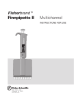
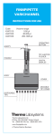
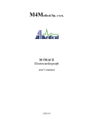
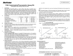
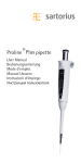
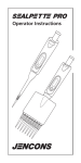
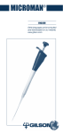
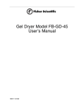
Fisherbrand ®
Finnpipette II
Digital
R
Fisherbrand
Finnpipette®
10.0
Finnpipette®
1.0 0
Fisherbrand
R
INSTRUCTIONS FOR USE
2000 PARK LANE
Pittsburgh PA 15275
800-766-7000
1
00
1 0npipette
R
Fin
A1 2 3 4
A1 2 3 4
B
C
B
C
4
6
A1 2 3 4
A1 2 3 4 5
B
C
B
C
5
7
1
1000
1 0 0 0
Finnpipette
2
11
®
9
3
12
10
2
CONTENTS
PRODUCT DESCRIPTION
PIPETTE OPERATION
PIPETTING TECHNIQUES
CALIBRATION
MAINTENANCE
TROUBLE SHOOTING
PACKAGE
SPARE PARTS
8
13
A
B
C
14
3
4
4
5
7
9
11
11
12-13
PRODUCT DESCRIPTION
The Fisher
Fisherbrand Finnpipette II is a manual digital pipette. It operates
on the air displacement principle (i.e. an air interface) and uses
detachable, disposable tips.
The adjusted delivery volume is displayed digitally on a readout window
on the handle.
Fisherbrand® Finnpipette II pipettes
The eleven different models of Fisher
cover a volume range from 0.2 µl to 10 ml.
Fisher
Catalog Number
Volume Range
Tip Size
21377814
0.2 µl - 2 µl, micro
10
21377815
0.5 µl - 10 µl, micro
10
21377816
0.5 µl - 10 µl
250 Universal, 200 Ext
21377817
2 µl - 20 µl
250 Universal, 300, 200 Ext
21377818
5 µl - 50 µl
250 Universal, 300, 200 Ext
21377819
10 µl - 100 µl
250 Universal, 300, 200 Ext
21377820
20 µl - 200 µl
250 Universal, 300, 200 Ext
21377821
100 µl - 1000 µl
1000,1000 Ext
21377822
200 µl - 1000 µl
1000
21377823
1 ml - 5 ml
5 ml
21377824
2 ml - 10 ml
10 ml
®
1 DIGITAL DISPLAY
The adjusted delivery volume is clearly indicated in the large digital
display on the handle.
RAW MATERIALS
The Fisher
Fisherbrand® Finnpipette II is made of mechanically durable and
chemically resistant materials.
PIPETTE OPERATION
SETTING THE DELIVERY VOLUME
the delivery volume using the push button on the top of the
2 1. Set
pipette.To increase the delivery volume, turn the push button
counterclockwise. To decrease the delivery volume, turn it clockwise.
2. Make sure that the desired delivery volume clicks into place and
that the digits are completely visible in the display window.
1 3. Do not set volumes outside the pipette´s specified volume range.
Using excessive force to turn the push button outside the range
may jam the mechanism and eventually damage the pipette.
4
TIP EJECTION
3
To help eliminate the risk of contamination, each pipette is fitted with a
tip ejectorsystem.
The tip ejector system consists of a soft-touch tip ejector and specially
designed gearing mechanism. To release the tip, point the pipette at
suitable waste receptacle and press the tip ejector with your thumb.
SAFETY LABEL
13
You can mark the pipette application your initials the calibration date,
etc. on the safety label.
Remove the clear plastic window on the edge closest to the push
button (use the service tool that comes with the pipette, or a
screwdriver). Mark the adhesive label with a felt-tipped or other pen and
snap the window back in place.
SHELF HANGER
14
You can attach the pipette shelf hanger on a counter, pipette stand or
anywhere where you want to hang your pipette.
Clean the area where you plan to attach the shelf hanger. Apply two
stickers to the underside of the shelf hanger. Press the shelf hanger
firmly into place -- on a shelf, countertop or pipette stand. To use, hang
the grippy finger rest on the shelf hanger.
PIPETTING TECHNIQUES
Push and release the push button slowly at all
Figures 4-7:
times particularly when working with high
A = Ready position
viscosity liquids. Never allow the push button to
B = First stop
snap back.
C = Second stop
Make sure that the tip is firmly attached to the
tip cone. Check for foreign particles in the tip.
Before you begin your actual pipetting work, fill and empty the tip 2-3
times with the solution that you will be pipetting. Hold the pipette in an
upright position while aspirating liquid. The grippy should rest on your
index finger. Make sure that the tips, pipette and solution are at the
same temperature.
FORWARD TECHNIQUE
4
Fill a clean reagent reservoir with the liquid to be dispensed.
1. Depress the push button to the first stop.
2. Dip the tip under the surface of the liquid in the reservoir to a depth
of about 1 cm and slowly release the push button. Withdraw the tip
from the liquid touching it against the edge of the reservoir to
remove excess liquid.
5
3. Deliver the liquid by gently depressing the push button to the first
stop. After a delay of about one second, continue to depress the
push button all the way to the second stop. This action will empty
the tip.
4. Release the push button to the ready position. If necessary, change
the tip and continue pipetting.
5 REVERSE TECHNIQUE
The reverse technique is suitable for dispensing liquids that have a high
viscosity or a tendency to foam easily. The technique is also
recommended for dispensing very small volumes. Fill a clean reagent
reservoir with the liquid to be dispensed.
1. Depress the push button all the way to the second stop.
2. Dip the tip under the surface of the liquid in the reservoir to a depth
of about 1 cm, and slowly release the push button.
This action will fill the tip. Withdraw the tip from the liquid touching
it against the edge of the reservoir to remove excess liquid.
3. Deliver the preset volume by gently depressing the push button to
the first stop. Hold the push button at the first stop. Some liquid
will remain in the tip and this should not be included in the delivery.
4. The remaining liquid should either be discarded with the tip or
pipetted back into the container.
6 REPETITIVE TECHNIQUE
The repetitive technique offers a rapid and simple procedure for
repeated delivery of the same volume. Fill a clean reagent reservoir
with the liquid to be dispensed.
1. Depress the push button all the way to the second stop.
2. Dip the tip under the surface of the liquid in the reservoir to a depth
of about 1 cm, and slowly release the push button. This action will
fill the tip. Withdraw the tipfrom the liquid touching against the
edge of the reservoir to remove excess liquid.
3. Deliver the preset volume by gently depressing the push button to
the first stop. Hold the push button at the first stop. Some liquid
will remain in the tip and this should not be included in the delivery.
4. Continue pipetting by repeating steps 2 and 3.
7 PIPETTING WHOLE BLOOD
(deproteinization in blood glucose determination, for example)
Use steps 1 and 2 of the forward technique to fill the tip with blood.
Wipe the tip carefully with a dry clean tissue.
1. Immerse the tip into the reagent and depress the push button to the
first stop, making sure the tip is well below the surface.
2. Release the push button slowly to the ready position. This will fill
the tip. Keep the tip in the solution.
6
3. Depress the push button to the first stop and release slowly. Keep
repeating this procedure until the interior wall of the tip is clear.
4. Finally, depress the push button all the way to the second stop to
completely empty the tip.
CALIBRATION
All Finnpipettes are factory calibrated and adjusted to give the volumes
as specified with distilled or deionized water. The pipettes are
constructed to permit re-adjustment for liquids of different
temperature and viscosity.
DEVICE REQUIREMENTS AND TEST CONDITIONS
An analytical balance must be used. The scale graduation value of the
balance should be chosen according to the selected test volume of the
pipette:
Volume range
readable graduation
under 10 µl
0.00 1 mg
10-100 µl
0.01 mg
above 100 µl
0.1 mg
Test liquid: Water, distilled or deionized, “grade 3” water conforming
ISO 3696. Tests are done in a draft-free room at a constant (±0.5°C)
temperature of water, pipette and air between 15°C to 30°C. The
relative humidity must be above 50%. Especially with volumes under 50
µl the air humidity should be as high as possible to reduce the effect of
evaporation loss. Special accessories, such as the evaporation trap,
are recommended.
PROCEDURE TO CHECK CALIBRATION
The pipette is checked with the maximum volume (nominal volume) and
with the minimum volume. A new tip is first pre-wetted 3-5 times and a
series of ten pipettings is done with both volumes. A pipette is always
adjusted for delivery (Ex) of the selected volume.
Procedure:
1. Do 10 pipettings with the minimum volume.
2. Do 10 pipettings with the maximum volume.
3. Calculate the accuracy (A) and precision (cv) of both series.
4. Compare the results to the limits in the Table 1.
If the calculated results are within the selected limits, the adjustment
of the pipette is correct.
7
TABLE 1: Maximum permissible errors according ISO8655
8 ADJUSTMENT
Adjustment is done with
the service tool.
1. Place the service tool
into the openings of the
calibration nut at the
top of the handle.
2. Turn the service tool
clockwise to increase,
or counterclockwise to
decrease the volume.
3. After adjustment check
the calibration according
to the instructions above.
FORMULAS FOR
CALCULATING
RESULTS
Range
Volume
µl
0,2-2 µl
2
0.2
0,5-10 µl
10
1
2-20 µl
20
2
5-50 µl
50
5
10-100 µl
100
10
20-200 µl
200
20
200-1000 µl 1000
200
100-1000 µl 1000
100
1-5 ml
5000
1000
2-10 ml
10000
2000
Accuracy
µl
%
±0.080 ±4
±0.080 ±40
±0.120 ±1.2
±0.120 ±12
±0.20 ±1.0
±0.20 ±10.0
±0.50 ±1.0
±0.50 ±10
±0.80 ±0.8
±0.80 ±8.0
±1.60 ±0.8
±1.60 ±8.0
±8.0
±0.8
±8.0
±4.0
±8.0
±0.8
±8.0
±8.0
±40.0 ±0.8
±40.0 ±4.0
±60.0 ±0.6
±60.0 ±3.0
Precision
s.d. µl cv%
0.040 2.0
0.020 20.0
0.080 0.8
0.080 8.0
0.10
0.5
0.10
5.0
0.20
0.4
0.20
4.0
0.30
0.3
0.30
3.0
0.60
0.3
0.60
3.0
3.0
0.3
3.0
1.5
3.0
0.3
3.0
3.0
15.0
0.3
15.0
1.5
30.0
0.3
30.0
1.5
Conversion of mass to volume
V = (w + e) x Z
V = volume (µl)
w = weight (mg)
e = evaporation loss (mg)
Z = conversion factor for mg/µl conversion
Evaporation loss can be significant with low volumes. To determine
mass loss, dispense water to the weighing vessel, note the reading and
start a stopwatch. See how much the reading decreases during 30
seconds (e.g. 6 mg = 0.2 mg/s).
Compare this to the pipetting time from taring to reading. Typically
pipetting time might be 10 seconds and the mass loss is 2 mg (10 s x
0.2 mg/s) in this example. If an evaporation trap or lid on the vessel is
used the correction of evaporation is usually unnecessary.
The factor Z is for converting the weight of the water to volume at test
temperature and pressure. A typical value is 1.0032 µl/mg at 22°C and
95 kPa. See the conversion table on page 15.
Accuracy (systematic error)
Accuracy is the difference between the dispensed volume and the
selected volume of a pipette.
A = V - V0
A = accuracy
V = mean volume
V0 = nominal volume
Accuracy can be expressed as a relative value: A% = 100% x A / V0
8
Precision (random error)
Precision refers to the repeatability of the pipettings. It is expressed as
standard deviation (s) or coefficient of variation (cv)
n
s = standards deviation
S (V - V ) 2
v = mean volume
S = i=1 i
n = number of measurements
n -1
Standard deviation can be expressed as a relative value (CV)
CV = 100% x S / V
MAINTENANCE
When the Fisher
Fisherbrand Finnpipette II is not in use, make sure it is
stored in an upright position. We recommend a Finnpipette stand for
this purpose.
®
SHORT-TERM CHECKING
The pipette should be checked at the beginning of each day for dust and
dirt on the outside surfaces of the pipette.
Particular attention should be paid to the tip cone. No other solvents
except 70 % ethanol should be used to clean the pipette.
LONG-TERM MAINTENANCE
If the pipette is used daily it should be checked every three months. The
servicing procedure starts with the disassembly of the pipette.
DISASSEMBLING 0.2-50 µl PIPETTES
1. Press the tip ejector.
9
2. Insert the maintenance pliers under the ejector bar to release the
tip ejector.
3. Remove the tip cone by pressing with maintenance pliers.
10
4. Pull out the piston and the spring.
5. Keep the tip cone vertically and push out with piston the rest of the
piston assembly. Then keep the tip cone upside down and tap all
parts from tip cone. Remember keep all parts in order on table for
reassembly.
6. Clean the piston, the piston spring and the O-rings with a dry
napless cloth.
7. Check the tip cone for foreign particles.
8. Grease the cleaned parts with the lubricant that comes with the pipette.
9. Reassemble the pipette components.
All 0.2-50 µl: First, slide the spring 14, spring support 15 and tube15
16 back on the piston. Compress the spring with fingers by pressing
piston and spring support 15 agains each other.
5-50 µl: Slide bigger O-ring 17, smaller O-ring 18, (2-20µl bigger Oring 18a, smaller O-ring 18b), spring support 19 (sharp edges
against spring) and small spring 20 on the piston.
9
0.5-10 µl: First slide O-ring tube 17 (larger hole first), bigger O-ring
18, smaller O-ring 19 and O-ring support 20 on the piston. Then slide
small spring 21, spring support 22 (sharp edges against spring) and
O-ring 22 on the O-ring support 20.
0.2-2 µl: First slide O-ring tube 17 (larger hole first) and sealing
combination 18 on the piston. Then slide small spring 19, spring
support 20 (sharp edges against spring) and O-ring 21 on the sealing
combination 18.
All 0.2-50 µl: Carefully slide the entire assembly into the tip cone
and release your fingers.
10. With the push button depressed all the way carefully attach the tip
cone to the handle so that the adapter opening is on the tip ejector
side. Do not bend the thin piston wire when assembling. Press in
the snap joints.
11. Assemble the tip ejector and check the calibration according to the
instructions.
DISASSEMBLING 50-1000 µl PIPETTES
9 1. Press the tip ejector.
2. Insert the pliers under the ejector bar to release the tip ejector.
10 3. Remove the tip cone using the maintenance pliers.
4.
5.
6.
7.
8.
Pull out the piston.
Remove the O-ring, O-ring support and spring from the tip cone.
Clean the piston, the piston spring and the O-ring with a dry napless cloth.
Check the cylinder for foreign particles.
Grease the cleaned parts with the lubricant that comes with the
pipette.
9. Slide parts over the piston pressing down the large spring. Attach
the tip cone to the handle so that the adapter opening is on the tip
ejector side, and press in the snap joints.
10. Check the calibration according to the instructions.
DISASSEMBLING 1-10 ml PIPETTES
9 1. Press the tip ejector.
2. Insert the pliers under the ejector bar to release the tip ejector.
10 3. Remove the part 2 from part 1 of the tip ejector using the
maintenance pliers to release the snap joint.
12 4. Remove the cylinder by pressing part 1 of the tip ejector firmly
towards the cylin der.This action releases the snap joint so you can
remove the cylinder.
5. Clean the O-ring and cylinder. Regrease the O-ring and the cylinder.
6. Assemble the parts in the opposite order of disassembly. All joints
are snap fit and can be pushed together by hand. Be careful not to
bend the pipette during assembly because this could damage the
snap joints or the piston.
7. Check the calibration according to the instructions.
10
TROUBLE SHOOTING
The table below lists possible problems and their solutions.
Defect
Leakage
Possible reason
Tip incorrectly attached
Foreign particles
between tip and tip cone
Foreign particles between the
piston, the O-ring and the
cylinder
Insufficient amount of grease
on cylinder and O-ring
O-ring damaged
Inaccurate Incorrect operation
dispensing Tip incorrectly attached
Calibration altered: caused
by misuse, for example
Inaccurate Unsuitable calibration.
dispensing High viscosity liquids may
with certain require recalibration.
liquids
Solution
Attach firmly
Clean tip cones attach
new tips
Clean and grease O-ring
and cylinder.
Grease accordingly
Change the O-ring
Follow instructions carefully
Attach firmly
Recalibrate according to
instructions
Recalibrate with
the liquids in question.
PACKAGE
The Fisherbrand Finnpipette II is shipped in a specially designed
package containing the following items:
®
1. The Finnpipette
2. Service tool
3. Maintenance pliers
4. Tube of grease
5. Instruction manual
6. Calibration certificate
7. Shelf hanger
8. Two stickers
CAUTION!
The Fisherbrand® Finnpipette II is designed to allow easy in-lab
service. If you would prefer to have us or your local representative
service your pipette, please make sure that the pipette has been
decontaminated before you send it to us.
Please note that the postal authorities in your country may prohibit
or restrict the shipment of contaminated material by mail.
11
12
10
4
3
2-10 ml
2
1
10
6
1-5 ml
5
17
16
15
15
16
14
13
14
13
16
15
14
13
17
16
15
14
13
18 a
17
16
15
14
13
17
16
15
14
13
100-1000µl 20-200µl
0,5-10µl
5-50µl
200-1000µl
2-20µl
10-100µl
16
15
14
13
0,2-2µl
13
15
14
13
12
11
14
13
12
11
16
15
12
11
10
12
11
10
12
11
10
12
11
10
20
19
18
12
11
10
20
18 b
19
10
23
22
21
20
19
18
11
a b
12
10
20
21
19
18
17
12
11
SPARE PARTS
15 Figure 15 lists spare parts and reorder numbers
All
1.
2.
3.
4.
20-200µl
10593720
2900580
10593050
1527200
2-10ml
5. 10592550
6. 2207450
10. 10593660
11. 2206730
12. 1033050
13. 10593440
14. 10593670
1-5ml
5.
6.
10.
11.
12.
13.
14.
15.
16.
10592540
2207440
10593680
2206720
1030230
10593130
10593690
1058180
1131940
5.
6.
10.
11.
12.
13.
14.
15.
16.
2-20µl
10592520
2207410
10593420
10593630
10593110
1053840
1130510
1053860
1030160
10-100µl
5.
6.
10.
11.
12.
13.
14.
15.
16.
10592520
2207400
10593620
10593630
10593110
2206600
1131810
10593340
1030510
5-50µl
5.
6.
10.
100-1000µl /
11.
200-1000µl
12.
5. 10592530
13.
6. 2207420 / 100µl 14.
6. 2207430 / 200µl 15.
10. 10593410
16.
11. 10593630
17.
12. 10593100
18.
13. 10589450
19.
14. 1130560
20.
15. 1130550
16. 1054260
17. 1030020
10592510
2207390
10593430
10593630
10593110
2206430
1131810
10593340
10593330
1030500
1033060
10593500
1132000
14
5. 10592510
6. 2207380
10. 10593090
11. 10593630
12. 10593110
13. 2206440
14. 1131810
15. 10593340
16. 10593330
17. 10593320
18. a 1030380
18. b 1033110
19. 10593360
20. 1132120
0,5-10µl
5. 10592500
6. 2207370
10. 10593090
11. 10593630
12. a 10593110
12. b 10593120
13. 2205710
14. 1131810
15. 10593340
16. 10593330
17. 10593310
18. 1030170
19. 1030060
20. 10593290
21. 1131800
22. 10593360
23. 1030170
Shelf hanger
2206740
0,2-2µl
5.
6.
10.
11.
12.
13.
14.
15.
16.
17.
18.
19.
20.
21.
10592560
2207360
10593090
10593630
10593120
2205700
1131810
10593340
10593330
10593300
2205730
1131800
10593360
1030170
Temperature
°C
Air pressure
hPA (mbar)
800
853
907
960
1013
1067
15
15.5
16
1.0018
1.0018
1.0019
1.0018
1.0018
1.0020
1.0019
1.0019
1.0020
1.0019
1.0020
1.0021
1.0020
1.0020
1.0021
1.0020
1.0021
1.0022
16.5
17
17.5
1.0020
1.0021
1.0022
1.0020
1.0021
1.0022
1.0021
1.0022
1.0023
1.0022
1.0022
1.0023
1.0022
1.0023
1.0024
1.0023
1.0023
1.0024
18
18.5
19
1.0022
1.0023
1.0024
1.0023
1.0024
1.0025
1.0024
1.0025
1.0025
1.0024
1.0025
1.0026
1.0025
1.0026
1.0027
1.0025
1.0026
1.0027
19.5
20
20.5
1.0025
1.0026
1.0027
1.0026
1.0027
1.0028
1.0026
1.0027
1.0028
1.0027
1.0028
1.0029
1.0028
1.0029
1.0030
1.0028
1.0029
1.0030
21
21.5
22
1.0028
1.0030
1.0031
1.0029
1.0030
1.0031
1.0030
1.0031
1.0032
1.0030
1.0031
1.0032
1.0031
1.0032
1.0033
1.0031
1.0032
1.0033
22.5
23
23.5
1.0032
1.0033
1.0034
1.0032
1.0033
1.0035
1.0033
1.0034
1.0035
1.0033
1.0035
1.0036
1.0034
1.0035
1.0036
1.0035
1.0036
1.0037
24
24.5
25
1.0035
1.0037
1.0038
1.0036
1.0037
1.0038
1.0036
1.0038
1.0039
1.0037
1.0038
1.0039
1.0038
1.0039
1.0040
1.0038
1.0039
1.0041
25.5
26
26.5
1.0039
1.0040
1.0042
1.0040
1.0041
1.0042
1.0040
1.0042
1.0043
1.0041
1.0042
1.0043
1.0041
1.0043
1.0044
1.0042
1.0043
1.0045
27
27.5
28
1.0043
1.0044
1.0046
1.0044
1.0045
1.0046
1.0044
1.0046
1.0047
1.0045
1.0046
1.0048
1.0045
1.0047
1.0048
1.0046
1.0047
1.0049
28.5
29
29.5
30
1.0047
1.0049
1.0050
1.0052
1.0048
1.0049
1.0051
1.0052
1.0048
1.0050
1.0051
1.0053
1.0049
1.0050
1.0052
1.0053
1.0050
1.0051
1.0052
1.0054
1.0050
1.0052
1.0053
1.0055
15
©2002 Fisher Scientific Litho in U.S.A. BN
16
1507910-02
For customer service, call 1-800-766-7000.
To fax an order, use 1-800-926-1166.
To order online: www.fishersci.com