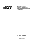
1
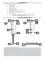
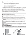
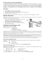
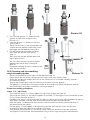
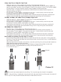
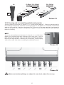
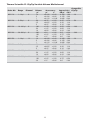
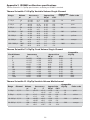
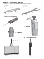
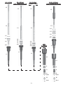
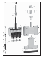
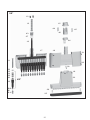
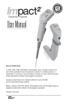
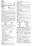
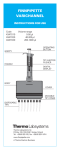
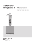
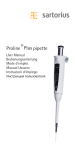
User Manual
Thermo Scientific F1-ClipTip
Single Channel
Multichannel
Instructions for Use
1
This product complies with the European Union Directive 98/79/EC, and it is marked with
a CE marking.
When the product is used in applications related to the Directive 98/79/EC, read the
additional information enclosed in the product package or contact the manufacturer at
[email protected] to ensure correct and safe use.
The CE mark covers the system containing the CE marked F1-ClipTip pipette and the CE
marked ClipTip pipette tips.
Product specifications are subject to change without prior notice. ClipTip is a registered
trademark of Thermo Fisher Scientific Inc. and its subsidiaries.
2
CONTENTS
1.
2.
3.
4.
5.
6.
7.
8.
9.
10.
INTRODUCTION
PACKAGE
MAIN ILLUSTRATION
SAFETY
OPERATION
CALIBRATION AND ADJUSTMENT
MAINTENANCE
STERILIZATION
TROUBLESHOOTING
APPENDICES
3
4
5
5
6
7
9
11
16
16
17
1. Introduction
Congratulations on your purchase of a Thermo Scientific® F1-ClipTip® pipette!
The F1-ClipTip is a general purpose air displacement micropipette. Its intended use is for aspirating
and dispensing liquids.
The F1-ClipTip features an innovative interlocking tip interface technology that locks the tip in place
ensuring secure tip attachment and preventing tips from being displaced in the middle of pipetting.
F1-ClipTip operates only with ClipTip® tips. For improved ergonomics, tips are attached and ejected
using minimal application pressure.
The F1-ClipTip product offering covers a volume range from 1 µl to 1000 µl and includes variable and
fixed volume single channel pipettes as well as multichannel pipettes. The convenient color coding*
system facilitates to identify the correct ClipTip by volume for use.
F1-ClipTip Variable Volume Single Channel
Cat. no.
Description
Volume range
4641170
4641180
4641190
4641200
4641210
4641220
4641230
F1-ClipTip 1-10 µl
F1-ClipTip 2-20 µl
F1-ClipTip 5-50 µl
F1-ClipTip 10-100 µl
F1-ClipTip 20-200 µl
F1-ClipTip 30-300 µl
F1-ClipTip 100-1000 µl
Increment
Color code
Compatible
ClipTip
0.02 µl
0.02 µl
0.1 µl
0.2 µl
0.2 µl
1 µl
1 µl
pink
pink
violet
yellow
yellow
orange
blue
ClipTip 20
ClipTip 20
ClipTip 50
ClipTip 200
ClipTip 200
ClipTip 300
ClipTip 1000
1–10 µl
2–20 µl
5–50 µl
10–100 µl
20–200 µl
30–300 µl
100–1000 µl
F1-ClipTip Fixed Volume Single Channel
Cat. no.
Description
4651170
4651180
4651190
4651200
4651210
4651220
4651230
4651240
4651250
4651260
4651270
F1-ClipTip 1 µl
F1-ClipTip 5 µl
F1-ClipTip 10 µl
F1-ClipTip 20 µl
F1-ClipTip 25 µl
F1-ClipTip 50 µl
F1-ClipTip 100 µl
F1-ClipTip 200 µl
F1-ClipTip 250 µl
F1-ClipTip 500 µl
F1-ClipTip 1000 µl
Volume range
1 µl
5 µl
10 µl
20 µl
25 µl
50 µl
100 µl
200 µl
250 µl
500 µl
1000 µl
Color code
Compatible ClipTip
dark blue
dark blue
dark blue
dark blue
dark blue
dark blue
dark blue
dark blue
dark blue
dark blue
dark blue
ClipTip 20
ClipTip 20
ClipTip 20
ClipTip 50
ClipTip 50
ClipTip 50
ClipTip 200
ClipTip 200
ClipTip 300
ClipTip 1000
ClipTip 1000
* color coding does not apply to fixed models
F1-ClipTip Multichannel
Cat. no.
Description
Channels
4661110
4661120
4661130
4661140
F1-ClipTip 8-ch 1–10 µl
F1-ClipTip 8-ch 5–50 µl
F1-ClipTip 8-ch 10–100 µl
F1-ClipTip 8-ch 30–300 µl
4661150
4661160
4661170
4661180
F1-ClipTip 12-ch 1–10 µl
F1-ClipTip 12-ch 5–50 µl
F1-ClipTip 12-ch 10–100 µl
F1-ClipTip 12-ch 30–300 µl
Volume
range
Increment
8
8
8
8
1–10 µl
5–50 µl
10–100 µl
30–300 µl
12
12
12
12
1–10 µl
5–50 µl
10–100 µl
30–300 µl
4
Color code
Compatible
ClipTip
0.02 µl
0.1 µl
0.2 µl
1 µl
pink
violet
yellow
orange
ClipTip 20
ClipTip 50
ClipTip 200
ClipTip 300
0.02 µl
0.1 µl
0.2 µl
1 µl
pink
violet
yellow
orange
ClipTip 20
ClipTip 50
ClipTip 200
ClipTip 300
2. Package
The F1-ClipTip package contains the following items:
1. F1-ClipTip pipette
2. Service tool
3. Multichannel service tool
4. Tip fitting tool
5. ClipTip tip sample
6. Tube of grease (Order No. 2203130)
7. Instructions for Use
8. Calibration certificate / Warranty Certificate
9. Shelf hanger (Order No. 2206040)
10. Warning labels
11. O-ring Order No. 2214930 Single Channel Pipette (Scp) 300 (3 pcs)
Order No. 2215540 Scp 1000 (3 pcs)
Order No. 2214920 Multichannel Pipette (Mcp) (12 pcs)
3. Main Illustration
1
2
1
8
2
3
4
3
4
5
8
7
1
2
3
4
5
6
7
8
8
6
7
Pipetting and volume adjustment button
Adjustable finger rest
Tip ejector
Volume display
Space for personal ID tag
Tip fitting
Tip sealing O-ring
Color coding
5
8
6
3.1. Materials
The F1-ClipTip is made of mechanically durable and chemically resistant materials.
The F1-ClipTip pipette includes components which contain the antimicrobial additive, silver sodium
hydrogen zirconium phosphate. Silver is known to inhibit the growth of a broad spectrum of microorganisms. For waste disposal instructions, contact your local environmental agency. For more
information, contact us at [email protected].
Common laboratory disinfectants, such as 70 % ethanol, can be used without effect on antimicrobial
treatment.
Aggressive substances can damage the pipette or pipette parts. Check for material
compatibility before using organic solvents and aggressive chemicals.
ClipTip pipette tips are made of natural color virgin polypropolyene. The tips feature a hydrophobic
surface, which effectively prevents liquid retention. ClipTips pipette tips come in multiple packaging
options including racks and reload packs, in sterile and non-sterile versions. ClipTip tips are also available
with a filter and are certified free of human DNA, RNase, DNase, ATP and endotoxin contamination.
The material used in F1-ClipTip pipettes and ClipTip tips are as follows:
F1-CLIPTIP PIPETTES
Material
Component
External surfaces of the upper parts:
ABS/PC
PA
PEI
Foil
acrylonitrilebutadienstyrene/polycarbonate
polyamide
polyetherimide
Exterior and interior of lower parts:
PEI
PA
PVDF
EPDM
FVM
Steel
polyetherimide
polyamide
polyvinyldenfluoride
ethylene-propylene-diene rubber
fluorosilicone rubber
stainless steel
PP
PE
polypropylene
polyethylene
CLIPTIP TIPS
Tip
Filters
4. Safety
Cautions are marked with this symbol
.
4.1. Intended use
The intended use of the device is to transfer liquids in the volume range of 1 µl to 1000 µl.
The F1-ClipTip pipette and ClipTip tip are designed as a component of an analyzing system for an end
user, who is responsible for validating the system to ensure reliable and safe results.
Damage to health
Follow general procedures for hazard prevention and safety instructions; e.g. wear
protective clothing, eye protection and gloves.
For use and waste disposal of hazardous (e.g. radioactive and potentially infectious) material,
follow the safety instructions and general laboratory practice.
The pipette and tips are not intended for in vivo use. Do not use the pipette for pipetting any liquid
to be injected into a human body.
Do not eject the tip towards anybody.
The F1-ClipTip is to be used by trained personnel with required laboratory skills. The instructions for
use must be read prior to and during the use of the device (pipette and tip). The F1-ClipTip pipette can
be used between +4°C and +40°C.
6
Incorrect dispensing results
Performance may vary due to:
a. pipetting method (forward pipetting technique recommended)
b. temperature (air, liquid, vessel, pipette, and tip)
c. pressure
d. humidity
e. operator, e.g. thumb movement, pipetting angle
f. liquid density, viscosity and vapor pressure
g. type of tip
If the pipetting performance is critical to the outcome of a specific application, the result has to
be assured with an alternative test, and if this is not an option, by duplicate testing.
The possibility of an incorrect volume delivery during pipetting cannot be entirely mitigated.
To avoid inaccurate dispensing and/or leakage, check that the tip is properly attached to
the pipette.
When rotating the volume adjustment button, do not exceed the volume range of the pipette.
Otherwise the pipette may be damaged or affect pipetting performance.
Pipetting performance cannot be guaranteed if the tip is reused.
Choose only a tip and pipette with matching color coding.
5. Operation
Cautions for incorrect operation
For optimum performance, make sure that the tips, pipette and solution are at the same
temperature.
Before you begin your actual pipetting, fill and empty the tip three to five times with the
solution that you will be pipetting.
Push and release the pipetting button slowly at all times particularly when working with high
viscosity liquids. Never allow the pipetting button to snap back.
Do not hold the pipette horizontally or upside down when there is liquid inside the tip. Sample
liquid may enter the pipette, which will affect the pipetting performance and may damage
the pipette.
Operate the pipetting button gently. If it is quickly released, sample liquid may enter the pipette,
which will affect the pipetting performance and may damage the pipette.
Follow the ergonomic guidelines for laboratory work to minimize the risk of repetitive strain
injury (RSI).
5.1 ID-tag
You can mark the pipette ID-tag with your initials, pipetting application or calibration date. Remove
the pipette’s module to replace the tag. Mark the label and slide the tag together with the holder
back to its slot (Picture 1).
5.2 Adjusting the finger rest
The finger rest supports the position of the pipette on the index finger, enhancing ergonomics. The
finger rest can be adjusted by rotating it 60 degrees in both directions from the center position
(Picture 2). Usually right-handed operators turn it left (counter clockwise) to achieve the best possible
position for the thumb to eject the tip.
Picture 1
Picture 2
7
5.3 Setting the delivery volume
1. Set the delivery volume using the volume adjustment
button on the top of the pipette (Picture 3). Pull the
button to activate the volume setting.
2. To increase the delivery volume, turn the button
counterclockwise. To decrease the delivery volume,
turn it clockwise.
3. Lock the volume by pushing the button down.
4. Check the volume on the display.
NOTE! Do not set volumes outside the pipette´s specified
volume range. Using excessive force to turn the volume
adjustment button outside the range may jam the
mechanism and eventually damage the pipette.
1
+
2
Picture 3
5.4 Tip attachment
1. To attach the tip, guide the pipette into a ClipTip in a rack
and press with light force until the tip is attached. A delicate
click sound will indicate that the tip is attached. The tip is
attached when the clips* (Picture 4) are locked to the tip fitting.
Do not use excessive force when attaching the tips as the
device requires minimum attachment force.
2. Lift the pipette.
3. If the tip is not attached, repeat Steps 1 and 2.
*
Incorrect use of tips
Use only ClipTip tips with an F1-ClipTip pipette.
Picture 4
Check that all clips are locked to ensure tip sealing.
ClipTip tips are designed for single use only.
To ensure sterility and purity of tips check that the package is unbroken. For sterile tips also
ensure that the indicator dot is red.
Check that the tip is complete and unbroken. Check for foreign particles in the tip.
Check that the filter tips have filters in place and that each filter is unbroken and not tilted.
5.5 Aspirating and dispensing liquid
1. Fill a suitable vessel with the liquid to be dispensed.
2. Depress the pipetting button to the first stop (Picture 5).
3. Dip the tip under the surface of the liquid
1 2 3 4
in the reservoir to a depth of about 1 cm
and slowly release the button.
Withdraw the tip from the liquid by moving
it against the edge of the reservoir to
remove excess liquid.
4. Deliver the liquid by gently depressing the
button to the first stop. After a delay of
about one second, continue to depress the
button all the way to the second stop. This
action will empty the tip.
5. Withdraw the tip by moving it against the edge of the target container.
Picture 5
Ensure proper functioning of F1-ClipTip 1-10µl multichannel and 1-50 µl
single channel pipettes
The F1-ClipTip 1-10µl multichannel and 1-50 µl single channel pipettes utilize an innovative super
blow-out piston technology to ensure efficient liquid delivery with small volumes. In pipettes with
the super blow-out piston three separate movements are observed (Picture 6) when the plunger is
pressed down to dispense liquid:
1. Primary plunger movement – delivers the set volume amount
2. Blow-out – additional phase to dispense residual liquid
3. Super blow-out – enhances the effectiveness of blow-out
8
Picture 6
Plunger in up position
Plunger in down position
When the pipette is not used for a period of time, the plunger movement may become stiff due to
hardening of grease. In rare cases this can affect the functionality of the super blow-out piston,
which can become temporarily jammed. To ensure proper functionality it is recommended to press
the plunger several times to the final stop (step 3 in picture) before dosing the sample liquid. This
releases the piston and re-distributes the lubricant.
NOTE! If the super blow-out piston is jammed, increased force might be required to release it. Ensure
that plunger moves to the down position (Picture 6).
For more information about different pipetting techniques, check the Good Laboratory Pipetting
Guide available at www.thermoscientitific.com/GLP.
5.6 Tip ejection
To release the tip, point the pipette at a suitable waste receptacle and press the tip ejector with
your thumb.
6. Calibration and Adjustment
6.1 Factory calibration limits
F1-ClipTip pipettes are factory calibrated and adjusted to give the volumes as specified with distilled
or deionized water using the forward pipetting technique. Manufacturer specifications are shown on
the pipette calibration certificate and in Appendix 2.
Cautions for calibration and pipette adjustment
It should be noted that the use of different pipetting techniques may affect the calibration
results. The pipettes are constructed to permit re-adjustment for other pipetting techniques
or liquids of different temperature and viscosity.
The performance of a new and serviced pipette must be checked and documented.
The manufacturer’s specifications should be used as guidelines and the user should establish
acceptable imprecision and inaccuracy performance limits (ISO 8655).
The user determines the performance and applicability of the pipette and tip combination
for a particular application and determine the required interval for performance checking.
Before starting the actual dosing, pre-rinse the tip with the liquid by filling and emptying the
tip three to five times to improve accuracy and precision.
6.2 Test conditions and equipment
An analytical balance must be used. The scale graduation value of the balance should be chosen
according to the selected test volume of the pipette:
Volume range
Readable graduation
under 10 µl
0.001 mg
10–100 µl
0.01 mg
above 100 µl
0.1 mg
The test liquid is deionized distilled “grade 3” water in compliance with ISO 3696. Tests are done in a
draft-free room at a constant (±0.5°C) temperature between 15°C to 30°C. The relative humidity must
be above 50%. Especially with volumes under 50 µl, air humidity should be as high as possible to reduce
the effect of evaporation loss. Special accessories, such as an evaporation trap, are recommended.
9
6.3 Procedure to check calibration
The pipette is checked at maximum volume (nominal volume) and minimum volume. A new tip is
first pre-wetted three to five times and a series of ten pipettings is done at both volumes. A pipette
is always adjusted according to the delivery of the selected volume. Use of the forward pipetting
technique is recommended. The maximum permissible errors are valid for the forward pipetting
method. It is recommended to use the ISO8655 calibration limits in Appendix 3 or user-defined
specifications.
Procedure:
1. Do 10 pipettings at the minimum volume.
2. Do 10 pipettings at the maximum volume.
3. Calculate the inaccuracy (A) and imprecision (CV) of both series.
4. Compare the results to the limits.
If the calculated results are within the selected limits, the adjustment of the pipette is correct.
Pipette adjustment
Adjustment is done only for one volume. The recommended adjustment volume is the minimum
volume or 10% of the maximum volume.
1. Fit the service tool (Picture 7) into the openings of the
calibration nut at the top of the handle.
2. Turn the service tool clockwise to increase, or
counterclockwise to decrease the volume.
3. After adjustment, check the calibration according to
the instructions above.
Formulas for calculating results
Conversion of mass to volume
Picture 7
V = (w + e) x Z V = volume (µl)
w = weight (mg)
e = evaporation loss (mg)
Z = conversion factor for µl/mg conversion
Evaporation loss can be significant at low volumes. To determine mass loss, dispense water into the
weighing vessel, note the reading and start a stopwatch. Check and note down how much the reading
decreases during 30 seconds (e.g. 6 mg = 0.2 mg/s).
Compare this to the pipetting time from taring to reading. Typically , the pipetting time might be 10
seconds and the mass loss is then 2 mg (10 s x 0.2 mg/s in this example). If an evaporation trap or lid
on the vessel is used, the correction of evaporation is usually unnecessary.
The factor Z is for converting the weight of the water to volume at the test temperature and pressure.
A typical value is 1.0032 µl/mg at 22°C and 95 kPa. See the conversion table in Appendix 1.
Inaccuracy (systematic error)
Inaccuracy is the difference between the dispensed volume and the selected volume of a pipette.
A = V - V0 A = inaccuracy
V = mean volume
V0 = nominal volume
Inaccuracy can be expressed as a relative value: A% = 100% x A / V0
Imprecision (random error)
Imprecision refers to the repeatability of the pipettings. It is expressed as standard deviation (S) or
coefficient of variation (CV)
S = standards deviation
V = mean volume
n = number of measurements
Standard deviation can be expressed as a relative value: CV = 100% x S / V
10
7. Maintenance
Cautions for incorrect maintenance
The pipette should be regularly serviced according to the instructions for use.
The pipette performance and functioning must be checked after maintenance.
Aggressive substances can damage the pipette or pipette parts. Check for material
compatibility before using organic solvents and aggressive chemicals.
Use only original Thermo Scientific spare parts and ClipTip tips.
Avoid excess grease. Use only the grease provided with the pipette.
If the pipette is used daily, it is recommended to service the pipette every three months.
When the F1-ClipTip is not in use, make sure it is stored in an upright position. We
recommend a pipette stand for this purpose.
When shipping the device for service or inspection, ensure that it is completely free of
chemical, biological, or radioactive contamination.
7.1 Daily maintenance
The pipette should be checked at the beginning of each day for dust and dirt on its outside surfaces.
Particular attention should be paid to the tip cone. To clean the pipette, we recommend wiping it with
a napless cloth wetted with 70% ethanol.
Leakage test
A leakage test can be performed at any time. It is recommended to be carried out after maintenance
or autoclaving.
Pre-wet the tip three to five times with water.
Aspirate a nominal volume of water into the tip.
Place the pipette on a stand or keep it firmly in your hand.
Wait for 20 seconds.
If a drop falls within 20 s, the pipette is leaking.
If the pipette leaks, see Chapter 9: “Troubleshooting” for possible reasons and solutions.
7.2 Periodic maintenance
The maintenance procedure starts with the disassembly of the pipette.
F1-ClipTip O-rings 5.1 are wear parts. It is recommended to replace O-rings regularly to ensure
proper sealing. Always replace the O-rings if they are worn or damaged.
7.2.1 Disassembly of single channel pipettes
1. Remove the tip fitting 5 (Picture 8).
To remove the tip fitting, place the end of tool 3 (Picture 9) without a metal rod on the tip fitting
tool against the tip fitting.
The tip fitting will guide the tool properly into place. Turn the tool counterclockwise ½ turn to
untighten the tip fitting.
Rotate the tip fitting tool and press the end with a metal rod through the tip fitting. Be careful not
to damage the O-ring inside the system with excess force.
Loosen the tip fitting with a tool and pull it out. Make sure that the O-ring comes out with the tip
fitting (Picture 10).
5.2
3
5
Picture 8
5.1
Picture 9
11
Picture 10
2. Press the tip ejector 4.1. Rotate the tip
ejector 10 clockwise and pull it out
(Picture 11).
3. Turn the tip cone 11 clockwise with the
service tool 1.
There are two slots in the service tool: the
smaller one for pipettes under 300 µl and
the bigger one for pipettes over 300 µl.
4. Pull out the piston assembly and other
parts from the handle with the tip
cone 11.
Then turn the tip cone upside down and
tap all parts from it.
You can check the parts of each specific
pipette from the pictures starting on
page 22.
Remember to keep all parts in order on the
table for reassembly.
4.1
1
10
11
7.2.2 Cleaning and reassembling
single channel pipettes
Picture 11
-
General maintenance instructions can be found on page 10.
Clean the piston, the piston spring and the O-rings with a dry napless cloth.
Check the tip cone for foreign particles or dirt. Immerse it in a suitable cleaning solution.
Dry before assembly.
- Grease the cleaned parts with the lubricant that comes with the pipette.
- The pipette is assembled in the reverse order to disassembling. Check the volume-specific
reassembling of the piston assemblies starting on page 22.
Piston reassembly procedures
1-10µl, 1 / 5 / 10µl Fixed
- First slide the spring 21, O-ring support 22 and O-ring 23 onto the tube 20.
- Then slide the spring 13, the spring support 16 and tube 17, the bigger O-ring 18 and the smaller
O-ring 19 back onto the piston 12.
- Compress the spring 13 with your fingers by pressing the piston and the spring support 16 against
each other, and then slide the tube 20 with the remaining parts onto the piston.
- Hold the spring 13 compressed and carefully slide the entire assembly into the tip cone 11,
and then release the spring.
- Put the spring 15 and support 14 on top of the tip cone and carefully insert the tip cone
assembly 42 onto the handle 4 and tighten it by hand.
- Reassemble the tip ejector 10. Put the tip fitting 5 onto the end of the tip cone assembly
and tighten it with the tool. We recommend using a new O-ring during each maintenance.
12
2-20µl, 20µl Fixed, 5-50µl 25 / 50µl Fixed
- Slide the spring 13, spring support 16 and tube 17 back onto the piston 12.
- Compress the spring 13 with your fingers by pressing the piston 12 and the spring support 16
against each other, and then slide the bigger O-ring 18, the smaller O-ring 19, the spring support
20 and spring 21 (smaller diameter against spring support 20) onto the piston.
- Hold the spring 13 compressed and carefully slide the entire assembly into the tip cone 11,
and then release the spring.
- Put the spring 15 and support 14 on top of the tip cone 11 and carefully insert the tip cone
assembly 42 onto the handle 4 and tighten it by hand.
- Reassemble the tip ejector 10. Put the tip fitting 5 onto the end of the tip cone assembly and
tighten it with the tool. We recommend using a new O-ring during each maintenance.
10-100µl, 20-200µl, 100 / 200µl Fixed, 30-300µl, 250µl Fixed
- Slide the spring 13, spring support 16 and O-ring 17 back onto the piston 12.
- Slide the entire assembly into the tip cone 11.
- Put the spring 15 and support 14 on top of the tip cone 11 and carefully insert the tip cone
assembly 42 into the handle 4 and tighten it by hand.
- Reassemble the tip ejector 10. Put the tip fitting 5 onto the end of the tip cone assembly 42
and tighten it with the tool. We recommend using a new O-ring during each maintenance.
100-1000µl, 500 / 1000µl Fixed
- Put the O-ring 17 and support ring 16 onto the tip cone 11.
- Slide the spring 13 onto the piston 12 and slide the entire assembly into the tip cone 11.
- Put the spring 15 and support 14 on top of the tip cone 11 and carefully insert the tip cone
assembly 42 into the handle 4 and tighten it by hand.
- Reassemble the tip ejector 11. Put the tip fitting 5 onto the end of the tip cone assembly 42
and tighten it with the tool. We recommend using a new O-ring during each maintenance.
Reassembly of tip fitting 5 and O-rings 5.1 and 5.2
- Place the tip fitting onto the tool end with a metal rod so that the screw end is facing upwards.
Place the O-ring into the rod above the tip fitting or make sure that the O-ring is at the bottom of
the cylinder’s screw end.
Align the tool with the cylinder and carefully screw the tip fitting in by turning the tool clockwise.
Stop tightening when you feel resistance.
Rotate the tip fitting tool and tighten the tip fitting by using the end without a metal rod.
Check that there is no gap between tip fitting and cylinder (Picture 12).
- Fit in a new O-ring 5.1.
No gap
Picture 12
Be careful not to overtighten the tip fitting. This may damage the thread in the pipette.
NOTE! If the tip fitting is tightened using the end with the metal rod of tip fitting tool, the tool will
start to slip. This may disform the tool and make it more difficult to use.
13
7.2.3 Disassembly of multichannel pipettes
1. Remove and discard the O-ring and remove the tip fittings (Picture 8) with the Tip fitting tool
(Picture 9).
We recommend replacing the O-ring during each maintenance.
2. Press the tip ejector 4.1 down, whereupon it presses the tip ejector 23 down at the same
time. Keep the ejector cover manually in the down position and let the tip ejector rise to the
normal position, whereupon the parts snap apart revealing a slot 7. If needed, facilitate
lightly by hand.
3. Keep the handle 4 still and insert the second end of the service tool 2 into the slot and turn
clockwise to separate the handle and the module 6. from each other. Loosen until you can pull the
parts apart.
4. Pull the holder spring 13 downwards and remove the two locking pieces 12. Finally, remove
the holder spring carefully ensuring that the spring does not fly off.
5. Remove the two MCP adapter claws 44/45 and pull the MCP adapter 46 away. Remove the
MCP spring base 43 by pulling upwards.
6. Remove the two screws 19 and pull the tip ejector 23 into the down position as shown in
the picture on page 24.
7. While the tip ejector 23 is in the down position, open its upper end slightly on both sides and
pull downwards. Remove the fastening spring 22. Remove the ejector link 24. Press the piston bar
16 beam into the down position. Finally unfasten the four screws 20/21 and the tip ejector.
The ejector slide 25 and two springs 26 can be removed for maintenance. This does not belong to
the regular long-term service, however.
8. Disengage the housing bottom 17 and piston bar 16 from each other. You can disengage the tip
cone assembly 42 by pulling it away from the piston assembly 31. Disengage the piston assembly
by pulling it out sideways from the piston bar as shown in the picture on page 24. Remove the
piston spring 33.
7.2.4 Service instructions for multichannel pipette tip cones / cylinders
Volume: 1–10 µl
Disengage the tip cone cover 32 from the tip cone A (Picture 13) by easing it off with a flat-head
screwdriver. The tip cone cover and the interior parts of the tip cone, the second support 35, the
O-ring 37, the sealing casing 38, the dash spring 39, the spring support 40, and the O-ring 41, can all
be removed in order by using the piston assembly 31 as shown in the picture. If some parts remain in
the tip cone, they can be removed by turning the tip cone upside down and tapping it.
32
A
37
35
32
31
38
41 40
39
Picture 13
Volumes: 5–50 µl, 10–100 µl, and 30–300 µl
Disengage the tip cone cover 32 from the tip cone B (Picture 13) by easing it off with a flat-head
screwdriver. The tip cone cover and the interior parts of the tip cone, the O-ring spring 34, the
supporter ring 35, and the O-ring 36 ( 5–50µl/10–100µl: also O-ring 37), can all be removed in order
by using the piston assembly 31 as shown in the picture. If some parts remain in the tip cone, they
can be removed by turning the tip cone upside down and tapping it.
14
32
5-50μl/ 10–100μl
30–300μl
31
34
32
32
35
37
B
31
35
36
36
34
Picture 14
7.2.5 Cleaning and reassembling multichannel pipettes
See the cleaning instructions in Section 7.2.2 “Single channel pipettes”. Check the volume-specific
reassembling of the piston assemblies starting on page 24. The pipette is assembled in the reverse
order to disassembling. Note that the ejector link 24 must be in the down position simultaneously
with the tip ejector 23 as shown in the picture on page 24. Clean and lubricate the holder spring 13
before assembling.
NOTE!
To ensure even performance between all channels in a multichannel
pipette, all tip cones have to be changed at the same time, if any of
them needs to be changed. Don’t mix tip cones of different packages,
because one bag contains a matched set of tip cones. Place aligning
studs to the same side when assembling the module (Picture 1).
Picture 15
Picture 16
Make sure that the tip fittings are aligned in same level, adjust if necessary.
15
8. Sterilization
Before autoclaving, disassemble the tip fitting from the tip cone and autoclave them separately. After
autoclaving, the tip cone and tip fitting must be cooled to room temperature for at least two hours.
When reassembling, make sure that the tip cone and tip fitting are dry. We recommend checking
the calibration after every sterilization cycle. The effectiveness of the autoclaving must be verified
by the user.
8.1 Autoclavable parts:
Single and multichannel pipettes:
- Tip fitting (5)
- Tip fitting O-ring (5.1)
Single channel pipettes:
- Tip cone assembly (42)
Parts can be repeatedly autoclaved at 121°C (252°F) (2 ata) for 20 minutes.
9. Troubleshooting
The table below lists possible problems and their solutions.
Defect
Possible reason
Possible action
Leakage
• Tip fitting incorrectly attached or
loose
►Re-attach/tighten the tip fitting
or replace with new tip fitting(s)
using the tool.
►Discard the tip.
►Change the O-ring.
►Attach firmly.
►Clean the tip cones and attach
new tips.
►Clean and grease the O-ring and
cylinder.
►Grease accordingly.
• ClipTip clips are bent
• Tip fitting o-ring damaged
• Tip incorrectly attached
• Foreign particles between the tip
and the tip cone
• Foreign particles between the
piston, the O-ring and the cylinder
• Insufficient amount of grease on the
cylinder and the O-ring
• O-ring damaged
Inaccurate
dispensing
• Incorrect operation
• Tip incorrectly attached
• Calibration altered; caused by
misuse, for example
• Wrong tip
• Unsuitable calibration: a list of
factors is presented in Section 4.1
“Calibration and adjustment“
• Tip cone part 11 is loose
►Change the O-ring.
►Follow the instructions carefully.
►Attach firmly.
►Recalibrate according to the
instructions.
►Use the correct tip.
►Readjust the pipette.
• Pipette not serviced
►Tighten the tip cone firmly to the
handle.
►Perform pipette service.
Tip not ejecting
• Tip fitting not properly attached
• Uneven tip ejecting with the
multichannel
►Tighten the tip fitting.
►Tighten the tip fitting with the
tool or replace the tip fitting set.
Piston jammed
• Pipette has been unused for a long
period
• Grease is removed while pipetting a
highly volatile solvent repeatedly
►Remove the tip if attached.
Press the plunger to the second
stop and release several times
to re-apply the grease.
16
10. Appendices
Appendix 1. Conversion table
Value of the conversion factor Z (µl/mg), as a function of temperature and pressure, for distilled
water.
Temperature
°C
15.0
15.5
16.0
16.5
17.0
17.5
18.0
18.5
19.0
19.5
20.0
20.5
21.0
21.5
22.0
22.5
23.0
23.5
24.0
24.5
25.0
25.5
26.0
26.5
27.0
27.5
28.0
28.5
29.0
29.5
30.0
Air pressure
kPa
80
85
90
95
100
101.3
105
1.0017
1.0018
1.0019
1.0020
1.0021
1.0022
1.0022
1.0023
1.0024
1.0025
1.0026
1.0027
1.0028
1.0030
1.0031
1.0032
1.0033
1.0034
1.0035
1.0037
1.0038
1.0039
1.0040
1.0042
1.0043
1.0045
1.0046
1.0047
1.0049
1.0050
1.0052
1.0018
1.0019
1.0020
1.0020
1.0021
1.0022
1.0023
1.0024
1.0025
1.0026
1.0027
1.0028
1.0029
1.0030
1.0031
1.0032
1.0033
1.0035
1.0036
1.0037
1.0038
1.0040
1.0041
1.0042
1.0044
1.0045
1.0046
1.0048
1.0049
1.0051
1.0052
1.0019
1.0019
1.0020
1.0021
1.0022
1.0023
1.0023
1.0024
1.0025
1.0026
1.0027
1.0028
1.0029
1.0031
1.0032
1.0033
1.0034
1.0035
1.0036
1.0038
1.0039
1.0040
1.0041
1.0043
1.0044
1.0046
1.0047
1.0048
1.0050
1.0051
1.0053
1.0019
1.0020
1.0021
1.0021
1.0022
1.0023
1.0024
1.0025
1.0026
1.0027
1.0028
1.0029
1.0030
1.0031
1.0032
1.0033
1.0034
1.0036
1.0037
1.0038
1.0039
1.0041
1.0042
1.0043
1.0045
1.0046
1.0047
1.0049
1.0050
1.0052
1.0053
1.0020
1.0020
1.0021
1.0022
1.0023
1.0024
1.0025
1.0025
1.0026
1.0027
1.0028
1.0029
1.0031
1.0032
1.0033
1.0034
1.0035
1.0036
1.0037
1.0039
1.0040
1.0041
1.0042
1.0044
1.0045
1.0047
1.0048
1.0049
1.0051
1.0052
1.0054
1.0020
1.0020
1.0021
1.0022
1.0023
1.0024
1.0025
1.0026
1.0027
1.0028
1.0029
1.0030
1.0031
1.0032
1.0033
1.0034
1.0035
1.0036
1.0038
1.0039
1.0040
1.0041
1.0043
1.0044
1.0045
1.0047
1.0048
1.0050
1.0051
1.0052
1.0054
1.0020
1.0021
1.0022
1.0022
1.0023
1.0024
1.0025
1.0026
1.0027
1.0028
1.0029
1.0030
1.0031
1.0032
1.0033
1.0034
1.0036
1.0037
1.0038
1.0039
1.0040
1.0042
1.0043
1.0044
1.0046
1.0047
1.0048
1.0050
1.0051
1.0053
1.0054
17
Appendix 2. Manufacturer specification limits
Thermo Scientific F1-ClipTip Variable Volume Single Channel
Order No.
Range
4641170
1–10 µl
4641180
2–20 µl
4641190
5–50 µl
4641200
10–100 µl
4641210
20–200 µl
4641220
30–300 µl
4641230
100–1000 µl
Volume
µl
10
5
1
20
10
2
50
25
5
100
50
10
200
100
20
300
150
30
1000
500
100
Inaccuracy
µl
%
±0.100
±0.075
±0.025
±0.20
±0.15
±0.06
±0.30
±0.25
±0.15
±0.80
±0.60
±0.30
±1.2
±1.0
±0.36
±1.8
±1.5
±0.45
±6.0
±4.0
±1.0
±1.00
±1.50
±2.50
±1.00
±1.50
±3.00
±0.60
±1.00
±3.00
±0.80
±1.20
±3.00
±0.60
±1.00
±1.80
±0.60
±1.00
±1.50
±0.60
±0.80
±1.00
Compatible
Imprecision
ClipTip
SD µl
CV%
0.050
0.040
0.020
0.08
0.06
0.05
0.15
0.13
0.125
0.20
0.20
0.10
0.4
0.4
0.14
0.6
0.6
0.18
2.0
1.5
0.6
0.50
0.80
2.00
0.40
0.60
2.50
0.30
0.50
2.50
0.20
0.40
1.00
0.20
0.40
0.70
0.20
0.40
0.60
0.20
0.30
0.60
20
20
50
200
200
300
1000
Thermo Scientific F1-ClipTip Fixed Volume Single Channel
Order No.
4651170
4651180
4651190
4651200
4651210
4651220
4651230
4651240
4651250
4651260
4651270
Volume
µl
1
5
10
20
25
50
100
200
250
500
1000
Inaccuracy
µl
%
±0.040
±4.00
±0.070
±1.40
±0.090
±0.90
±0.14
±0.70
±0.15
±0.60
±0.30
±0.60
±0.40
±0.40
±0.80
±0.40
±1.0
±0.40
±1.5
±0.30
±3.0
±0.30
18
Imprecision
SD µl
CV%
0.040
4.00
0.070
1.40
0.080
0.80
0.100
0.50
0.125
0.50
0.20
0.40
0.30
0.30
0.600
0.30
0.75
0.30
1.5
0.30
3.0
0.30
Compatible
ClipTip
20
20
20
20
50
50
200
200
300
1000
1000
Thermo Scientific F1-ClipTip Variable Volume Multichannel
Order No. Range
Channel
4661110
1–10 µl
8
4661120
5–50 µl
8
4661130
10–100 µl
8
4661140
30–300 µl
8
4661150
1–10 µl
12
4661160
5–50 µl
12
4661170
10–100 µl
12
4661180
30–300 µl
12
Volume
µl
10
5
1
50
25
5
100
50
10
300
150
30
10
5
1
50
25
5
100
50
10
300
150
30
Compatible
Inaccuracy
Imprecision ClipTip
µl
%
SD µl CV%
±0.240 ±2.40
0.160 1.60
20
±0.200 ±4.00
0.150 3.00
±0.120 ±12.00 0.080 8.00
±0.75
±1.50
0.35 0.70
50
±0.625 ±2.50
0.30 1.20
±0.25
±5.00
0.10 2.00
±1.30
±1.30
0.50 0.50
200
±1.25
±2.50
0.60 1.20
±0.50
±5.00
0.20 2.00
±3.0
±1.00
0.9
0.30
300
±2.25
±1.50
0.75 0.50
±1.5
±5.00
0.6
2.00
±0.240 ±2.40
0.160 1.60
20
±0.200 ±4.00
0.150 3.00
±0.120 ±12.00 0.080 8.00
±0.75
±1.50
0.35 0.70
50
±0.625 ±2.50
0.30 1.20
±0.25
±5.00
0.10 2.00
±1.30
±1.30
0.50 0.50
200
±1.25
±2.50
0.60 1.20
±0.50
±5.00
0.20 2.00
±3.0
±1.00
0.9
0.30
300
±2.25
±1.50
0.75 0.50
±1.5
±5.00
0.6
2.00
19
Appendix 3. ISO8655 calibration specifications
Thermo Scientific F1-ClipTip specifications according to ISO8655 standard.
Thermo Scientific F1-ClipTip Variable Volume Single Channel
Range
Volume
µl
1–10 µl
10
1
2–20 µl
20
2
5–50 µl
50
5
10–100 µl
100
10
20–200 µl
200
20
30–300 µl
300
30
100–1000 µl 1000
100
Inaccuracy
µl
%
±0.120
±1.2
±0.120
±12
±0.20
±1.0
±0.20
±10.0
±0.50
±1.0
±0.50
±10
±0.80
±0.8
±0.80
±8.0
±1.60
±0.8
±1.60
±8.0
±4.0
±1.3
±4.0
±13
±8.0
±0.8
±8.0
±8.0
Imprecision
SD µl
CV%
0.080
0.8
0.080
8.0
0.10
0.5
0.10
5.0
0.20
0.4
0.20
4.0
0.30
0.3
0.30
3.0
0.60
0.3
0.60
3.0
1.5
0.5
1.5
5.0
3.0
0.3
3.0
3.0
Compatible
ClipTip
Color code
20
pink
20
pink
50
violet
200
yellow
200
yellow
300
orange
1000
blue
Thermo Scientific F1-ClipTip Fixed Volume Single Channel
Fixed Volume
µl
1
5
10
20
25
50
100
200
250
500
1000
Inaccuracy
µl
%
±0.050
±5.00
±0.125
±2.50
±0.120
±1.20
±0.20
±1.00
±0.50
±2.00
±0.50
±1.00
±0.80
±0.80
±1.60
±0.80
±4.00
±1.60
±4.00
±0.80
±8.00
±0.80
Imprecision
SD µl
CV%
0.050
5.00
0.075
1.50
0.080
0.80
0.10
0.50
0.20
0.80
0.20
0.40
0.30
0.30
0.60
0.30
1.50
0.60
1.50
0.30
3.00
0.30
Compatible
ClipTip
20
20
20
20
50
50
200
200
300
1000
1000
Thermo Scientific F1-ClipTip Variable Volume Multichannel
Range
Channel
1–10 µl
8, 12
5–50 µl
8, 12
10–100 µl 8, 12
30–300 µl 8, 12
Volume
Inaccuracy
µl
µl
%
10
±0.24
±2.4
1
±0.24
50
±1.0
±2.0
5
±1.0
±20
100
±0.80
±0.8
10
±0.80
±8.0
300
±8.0
±2.7
30
±8.0
±26.7
20
Compatible
Imprecision ClipTip
Color code
SD µl CV%
0.16
1.6
20
pink
±24
0.16
16
0.4
0.8
50
violet
0.4
8.0
0.30
0.3
200
yellow
0.30
3.0
3.0
1.0
300
orange
3.0
10.0
Appendix 4. Assembly and spare parts
* Available as a spare part. See model specific order numbers on page 26.
1062930
Multichannel service tool
1062800
Service and
adjustment tool
1
2
2215870 Tip fitting tool
3
* 4. Handle
* 5. Tip fitting
* 42. Tip cone assembly
* 50. Module
21
1–10μl
1μl / 5μl / 10μl Fixed
14
15
12
5–50μl
25 / 50 μl Fixed
2–20μl
20 μl Fixed
14
14
12
15
12
16
15
16
16
17
17
18*
17
18*
19*
19*
20
18*
20
21
19*
21
20
22
23*
13
21
11
All
1–300μl
13
11
13
11
10
9
8
6
5.2*
5*
5.1*
22
10–100μl
12
20–200μl
100 / 200 μl Fixed
12
30–300μl
250μl Fixed
100–1000μl
500 / 1000 μl Fixed
12
12
13
13
13
13
14
15
16
14
17*
15
16
17*
14
15
16
17*
14
15
16
17*
All
1–300μl
11
11
11
11
10
10
23
9
9
8
8
6
6
5.2*
5.2*
5*
5*
5.1*
5.1*
* 50
12
15
13
45
44
46
43
27
24
16
18
17
21
31
20
33
32
22
35
37
19
38
39
40
41
23
42*
30
26
5.2*
5*
25
5.1*
24
50*
12
15
13
44
45
46
43
27
24
16
17
18
21
31
20
22
33
32
34
35
36
30
5.2*
5*
5.1*
19
23
42*
26
25
25
F1-ClipTip single channel and multichannel spare part order numbers
Single Channel
1–10μl / 1μl / 5μl / 10μl Fixed
30–300μl / 250μl Fixed
4.
4.
4.
4.
5.
5.1.
5.2.
18.
19.
23.
42.
4.
4.
5.
5.1.
5.2.
17.
42.
2214000 1-10μl
2214070 Fix 1μl
2214080 Fix 5μl
2214090 Fix 10μl
11072080
2214930 3 pcs
1030060
1030380
1030060
1030170
2214180
100–1000μl
500μl / 1000μl Fixed
4.
4.
4.
5.
5.1.
5.2.
17.
42.
2–20μl / 20μl Fixed
4.
4.
5.
5.1.
5.2.
18.
19.
42.
2214010 2–20μl
2214100 Fix 20μl
11072080
2214930 3 pcs
1030060
1030380
1033110
2214190
5–50μl / 25μl / 50μl Fixed
4.
4.
4.
5.
5.1.
5.2.
18.
19.
42.
8-ch / 12-ch
4.
4.
4.
4.
5.
5.1.
5.2.
42.
42.
42.
42.
2214030 10–100μl
11072080
2214930 3 pcs
1030060
1030510
2214210
2214000 1–10μl
2214020 5–50μl
2214030 10–100μl
2214050 30–300μl
11072080
2214920 12 pcs
1030060
2214390 1–10μl 12 pcs
2214400 5–50μl 12 pcs
2214410 10–100μl 12 pcs
2214420 30–300μl 12 pcs
8-ch
50.
50.
50.
50.
20–200μl / 100μl / 200μl Fixed
4.
4.
4.
5.
5.1.
5.2.
17.
42.
2214060 100–1000μl
2214160 Fix 500μl
2214170 Fix 1000μl
11072200
2215540 3 pcs
1033410
1030020
2214240
Multichannel
2214020 5–50μl
2214110 Fix 25μl
2214120 Fix 50μl
11072080
2214930 3 pcs
1030060
1030500
1039060
2214200
10–100μl
4.
5.
5.1.
5.2.
17.
42.
2214050 30–300μl
2214150 Fix 250μl
11072080
2214930 3 pcs
1030060
1033330
2214230
2214040 20–200μl
2214130 Fix 100μl
2214140 Fix 200μl
11072080
2214930 3 pcs
1030060
1030160
2214220
2213620 1–10μl
2213630 5–50μl
2213640 10–100μl
2213650 30–300μl
12-ch
50.
50.
50.
50.
26
2213660 1–10μl
2213670 5–50μl
2213680 10–100μl
2213690 30–300μl
Appendix 5. ClipTip ordering information
Thermo Scientific ClipTip racked and sterile tips
Code
ClipTip
94410210
94410213
94410250
94410253
94410310
94410313
94410510
94410513
94410710
94410713
ClipTip 20
ClipTip 20, sterile
ClipTip 50
ClipTip 50, sterile
ClipTip 200
ClipTip 200, sterile
ClipTip 300
ClipTip 300, sterile
ClipTip 1000
ClipTip 1000, sterile
Volume
20 µl
20 µl
50 µl
50 µl
200 µl
200 µl
300 µl
300 µl
1000 µl
1000 µl
Qty
10x96/rack
10x96/rack
10x96/rack
10x96/rack
10x96/rack
10x96/rack
10x96/rack
10x96/rack
8x96/rack
8x96/rack
Thermo Scientific ClipTip reload inserts
Code
ClipTip
94410217
94410218
94410257
94410258
94410317
94410318
94410517
94410518
94410717
94410718
ClipTip 20
ClipTip 20, sterile
ClipTip 50
ClipTip 50, sterile
ClipTip 200
ClipTip 200, sterile
ClipTip 300
ClipTip 300, sterile
ClipTip 1000
ClipTip 1000, sterile
Volume
20 µl
20 µl
50 µl
50 µl
200 µl
200 µl
300 µl
300 µl
1000 µl
1000 µl
Qty
10x96/insert
10x96/insert
10x96/insert
10x96/insert
10x96/insert
10x96/insert
10x96/insert
10x96/insert
8x96/insert
8x96/insert
Thermo Scientific ClipTip filter tips , sterile
Code
ClipTip
Volume
Qty
94420213
94420253
94420313
94420513
94420713
ClipTip Filter 20
ClipTip Filter 50
ClipTip Filter 200
ClipTip Filter 300
ClipTip Filter 1000
20 µl
50 µl
200 µl
300 µl
1000 µl
10x96/rack
10x96/rack
10x96/rack
10x96/rack
8x96/rack
All ClipTip tips are certified to be free from RNase, DNase, DNA, ATP and pyrogens.
27
Appendix 6. F1-ClipTip and ClipTip compatibility table
ClipTipFilter1000
ClipTipFilter300
ClipTipFilter20
ClipTip1000
ClipTip300
ClipTip200
ClipTip50
ClipTip20
Filtertips
ClipTipFilter50
NonͲfiltertips
ClipTipFilter200
F1ͲClipTip1൞10ʅl
x
x
F1ͲClipTip2൞20ʅl
x
x
F1ͲClipTip5൞50ʅl
x
x
F1ͲClipTip10൞100ʅl
x
x
F1ͲClipTip20൞200ʅl
x
x
F1ͲClipTip30൞300ʅl
x
x
F1ͲClipTip100൞1000ʅl
x
x
F1ͲClipTip1ʅlfixedvolume
x
x
F1ͲClipTip5ʅlfixedvolume
x
x
F1ͲClipTip10ʅlfixedvolume
x
x
F1ͲClipTip20ʅlfixedvolume
x
x
F1ͲClipTip25ʅlfixedvolume
x
x
F1ͲClipTip50ʅlfixedvolume
x
x
F1ͲClipTip100ʅlfixedvolume
x
x
F1ͲClipTip200ʅlfixedvolume
x
x
F1ͲClipTip250ʅlfixedvolume
x
x
F1ͲClipTip500ʅlfixedvolume
x
x
F1ͲClipTip1000ʅlfixedvolume
x
x
F1ͲClipTip8Ͳch1൞10ʅl
x
x
F1ͲClipTip8Ͳch5൞50ʅl
x
x
F1ͲClipTip8Ͳch10൞100ʅl
x
x
F1ͲClipTip8Ͳch30൞300ʅl
x
x
F1ͲClipTip12Ͳch1൞10ʅl
x
x
F1ͲClipTip12Ͳch5൞50ʅl
x
x
F1ͲClipTip12Ͳch10൞100ʅl
x
x
F1ͲClipTip12Ͳch30൞300ʅl
x
x
28
Appendix 7. Pipette accessories
Multichannel stand
#9420390
F–stand
#9420400
Reagent reservoir
100 ml #95128085
Reagent reservoir
25 ml #95128093
Reagent reservoir
25 ml divided #951228095
29
[email protected]
www.thermoscientific.com/GLP
www.thermoscientific.com
thermoscientific.com
© 2015 Thermo Fisher Scientific Inc. All rights reserved. All trademarks are the property of Thermo Fisher
Scientific Inc. and its subsidiaries. Specifications, terms and pricing are subject to change. Not all products
are available in all countries. Please consult your local sales representative for details.
Thermo Fisher Scientific
Ratastie 2, P.O.Box 100
FI-01621 Vantaa
Finland
1508810-05
30