1
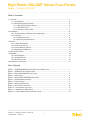
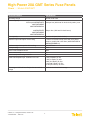
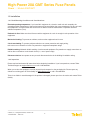
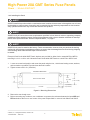
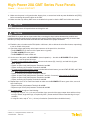
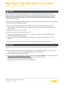
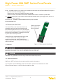
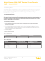
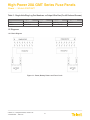
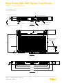
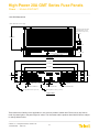
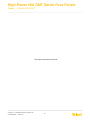
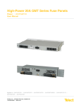
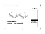
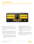
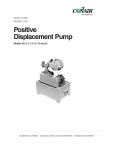
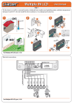
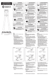
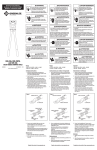
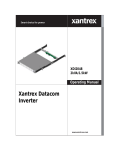
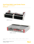
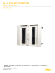
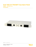
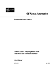
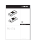
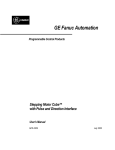
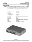
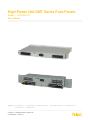
High-Power 20A GMT Series Fuse Panels Power :: 20HPGMTXX User Manual Applys to : 20HPGMT05R :: 20HPGMT05FR :: 20HPGMT05BNR :: 20HPGMT05BNR-24 :: 20HPGMT12R-75 :: 20HPGMT03R :: 20HPGMT02R © Telect, Inc., All Rights Reserved, 130339-7 A0 1.509.926.6000 :: telect.com High-Power 20A GMT Series Fuse Panels Power :: Models 20HPGMT Table of Contents 1.1 Overview ................................................................................................................................1 1.1.1 Specifications ..............................................................................................................2 1.1.2 Standard & Special Features ......................................................................................5 1.1.2.1 Bay & Failure Alarm Options ...............................................................................6 1.1.2.2 Fail-Safe Circuit ...................................................................................................7 1.1.2.3 Power-Line Noise Filter .......................................................................................7 1.2 Installation ..............................................................................................................................8 1.2.1 Rack-Mounting Conditions and Considerations ..........................................................8 1.2.2 Inspection ....................................................................................................................8 1.2.3 Installing the Panel .................................................................................................9 1.2.4 Replacing the Alarm Board ....................................................................................13 1.3 Service ................................................................................................................................. 13 1.3.1 Owner Maintenance ...................................................................................................13 1.3.2 In-Warranty Service ....................................................................................................14 1.3.3 Out-Of-Warranty Service ............................................................................................14 1.3.4 Repacking for Shipment .............................................................................................14 1.4 Parts & Accessories.............................................................................................................. 14 1.5 Diagrams .............................................................................................................................. 16 1.5.1 Block Diagram.............................................................................................................16 1.5.2 1RU Dimensions ........................................................................................................17 1.5.3 2RU Dimensions ........................................................................................................18 1.6 Certificate of Conformity ...................................................................................................... 19 List of Figures Figure 1 - 20HPGMT05BNR (1RU Panel) Front and Rear View ................................................1 Figure 2 - 20HPGMT12R-75 (2RU Panel) ..................................................................................1 Figure 3 - Model 20HPGMT05R (Front View) .............................................................................2 Figure 4 - Alarm Panel .................................................................................................................5 Figure 5 - Model 20HPGMT05BNR (Rear View) .........................................................................6 Figure 6 - Standard Alarm Hookups ............................................................................................6 Figure 7 - Alarm Hookups ............................................................................................................7 Figure 8 - Mounting Dimensions ..................................................................................................9 Figure 9 - Ground Lug Connection ............................................................................................ 10 Figure 10 - Compression Lug Inputs ..........................................................................................10 Figure 11 - Replacing the Alarm Board ...................................................................................... 13 Figure 12 - Power, Battery Return and Fuse Circuit .................................................................. 16 © Telect, Inc., All Rights Reserved, 130339-7 A0 1.509.926.6000 :: telect.com ii High-Power 20A GMT Series Fuse Panels Power :: Models 20HPGMT 1.1 Overview Telect’s High-Power 100A GMT Series Fuse Panels provide protected secondary distribution of -48 VDC power to telecommunications equipment at the bay level (20HPGMT05BNR-24 is 24VDC). Fuse panels are available for GMT outputs up to 20A per position in dual-circuit (10/10, 15/15, and 20/20) panel configurations. Standard features include • Dual-circuit, 100A input buses, -48 VDC (20HPGMT05BNR-24 is 24VDC) • Discrete GMT fuse positions: 20A capacity w/o fuse management for heat dissipation Figure 1 - 20HPGMT05BNR (1RU Panel) Front and Rear View • Alarm circuit board replaceable with panel in service (hot-swap) • Minimal rack space: one, 1.75”. • EIA or 2”. WECO rack unit (1RU) • for rear access connections; 2RU for • total front access of dual-circuit 10/10 configuration • 19”. or 23”. rack mounting, with mounting brackets provided. Dual-Circuit 20/20 Panel (20HPGMT02R) requires a 23-in. rack. Figure 2 - 20HPGMT12R-75 (2RU Panel) • Transparent terminal cover meets electrical and equipment safety standards. • Dummy GMT fuses are provided for all fuse holders. • Holes provided in chassis for inserting colored fuse designation pins • All 20HPGMT panels are NEBS (Level 3) and CE certified. • Fire rating: UL 94V-0 and/or VW-1 (for wiring) • All models except 20HPGMT05R are recognized by UL for USA and Canada. 20HPGMT05R is UL listed for USA and Canada. © Telect, Inc., All Rights Reserved, 130339-7 A0 1.509.926.6000 :: telect.com 1 High-Power 20A GMT Series Fuse Panels Power :: Models 20HPGMT Special features include • Bay Alarm Circuitry (20HPGMT05BNR and 20HPGMT05BNR-24) • Fail-Safe Circuitry (20HPGMT05FR only): load sharing permits either feed to power all loads if the other feed fails. • Noise Filter Circuitry (20HPGMT05BNR and 20HPGMT05BNR-24) Telect’s High-Power GMT Series Fuse Panels use discrete, not modular, GMT fuse holders, to limit heat buildup when using 15A and 20A GMT fuses. POWER Figure 3 - Model 20HPGMT05R (Front View) 1.1.1 Specifications Environment: Specifications: Humidity 5% to 85% and noncondensing Temperature range Altitude range Acoustic noise -5°C to 55°C (-23°F to 131°F) -197 ft to 13,100 ft (-60 m to 4000 m) 0 dBA above ambient Fit & Finish Specifications: Weights (Approximate) Specifications: Material (Custom color/finish available) Cold-rolled steel, powder-coat telephone grey, baked polyure- thane. Clear polycarbonate protective terminal cover. Weight © Telect, Inc., All Rights Reserved, 130339-7 A0 1.509.926.6000 :: telect.com 8 to 12 lb (~3.5 to 5.5 kg), depending on model 2 High-Power 20A GMT Series Fuse Panels Power :: Models 20HPGMT Mechanical Interface: Input terminals — Compression Specifications: Stud: Lugs: Cable: Output terminals — Wire binding / Compression Alarm terminals — Wire Wrap Ground terminals Torque: Screw: Wire: #6 Phillips* panhead 14 to 22 AWG, copper wire Lug: 10 to 22 AWG, copper wire Spacing: 3/8 in. (9.5 mm) centerline with barrier distance of 0.260 in. (6.6 mm) Torque: 9 in.-lb (~1.0 N•m), max. 0.045 in. square wirewrap pins on 0.156 in. centers. Use 18 to 22 AWG copper Screws: Lugs: Cable: * Screws with cross-recessed heads ⁄4-20 with nut. (Use 7/16-in. [12 mm] socket.) Dual-hole compression lug (5/8 in. center to center). 0.516 in. (13.4 mm), max. lug width Up to 1/0 AWG copper, depending on input interruption device 62 in.-lb (~6.8 N•m), max. 1 Torque: 2, #10 Phillips* panhead Single- or dual-hole compression lug (5/8 in. center to center). Dual-hole lug is recommended. Up to #6 AWG copper for single-hole lug (Conductor size depends on input interruption device.) 21 in.-lb (~2.5 N•m), max. Dimensions: Specifications: Dimensions (nominal) without brackets for 20HPGMT02R Width: Height: Depth: Dimensions (nominal) without brackets for all but 20HPGMT12R-75 & 20HPGMT02R Dimensions (nominal) without brackets for 20HPGMT12R-75 † See Pages 17 and 18 for exact dimensions. © Telect, Inc., All Rights Reserved, 130339-7 A0 1.509.926.6000 :: telect.com 3 Width: Height: Depth: 17 in. (432 mm) 1.75 in. (44.4 mm) 12 in. (305 mm) Width: Height: Depth: 17 in. (432 mm) 3.5 in. (89 mm) 7.5 in. (190 mm) 21 in. (533 mm) 1.75 in. (44.4 mm) 12 in. (305 mm) High-Power 20A GMT Series Fuse Panels Power :: Models 20HPGMT Electrical Interface: Specifications: Operating voltage Current capacity -48 Vdc, both sides All Except 20HPGMT05FR 20HPGMT05BNR 20HPGMT05BNR-24 Fuse capacity: 100A per bus (200A total for dual-circuit panels), max. 20HPGMT05FR 20HPGMT05BNR 20HPGMT05BNR-24 75A per bus (150A total for both buses) 20, 30, or 40 (total, both circuits) Maximum input interruption device rating • 125A for all models except those with noise filters. • 90A for models with noise filters (20HPGMT05NR & 20HPGMT05BNR-24) Maximum output interruption device rating 20A GMT fuse Interrupt rating 450A Short circuit withstand current 450A Alarm contact relay 2A Alarm board power rating @ 48 Vdc 1W Panel heat dissipation per 100A bus @% load 1.0W (3.4 Btu/hr) @ 0% 1.2W (4.1 Btu/hr) @ 25% 4.8W (16.5 Btu/hr) @ 50% 11.4W (38.7 Btu/hr) @ 75% 21.3W (72.6 Btu/hr) @ 100% Percentage of full load heat dissipa- tion at nominal voltage © Telect, Inc., All Rights Reserved, 130339-7 A0 1.509.926.6000 :: telect.com less than 1% of total load wattage 4 High-Power 20A GMT Series Fuse Panels Power :: Models 20HPGMT 1.1.2 Standard & Special Features The following table compares the features of all standard 20HPGMT panels. All panels include a rear or front transparent cover and most, except as footnoted in the following chart, can be mounted in either 19”. or 23”. racks. The paragraphs that follow briefly describe some of the standard and special features included with these panels. Table 1 - Product Comparison Chart Model No. Fuse Array -48 Vdc 20HPGMT05R X 20HPGMT05BNR X 20HPGMT05FR Dual 10/10 20HPGMT03R Dual 15/15 20HPGMT02R (23 inch only) Bay Alarm X 20HPGMT05BNR-24 20HPGMT12R-75 (Front Access - 2RU) -24 Vdc Dual 20/20 Noise Filter X X X X Fail-Safe Circuit X X X X X GMT fuses are available in capacities ranging from 0.18A to 20A. A unique feature of the Telect High-Power GMT Fuse Panel is that the fuse positions are oriented so the identification flags face down to provide easy location of a blown fuse when the panel is at the top position of a relay rack or bay. (GMT splash covers are optional for maximum safety when fuses blow.) Another unique feature of the GMT panels is a small hole below each fuse position to accommodate color-coded optional designation pins. Designation pins are useful for quickly identifying required fuse positions and rating of the fuses. The panel is delivered with dummy fuses in all positions. The standard front panel includes dual-color LEDs for power and failure alarms on the face of an easily removable/replaceable alarm card: • The POWER LEDs are green when power is on and red when power to that side goes off. • The FAIL ALARM LED is green when all installed fuses are OK and red when any installed, operable fuse blows. C Rev: A OHPGMT05R SN: 0206381 L#:E179636 WK-YR: 11-1999 US LISTED B POWER A POWER FAIL ALARM Below the LEDs and alarm card is a pull-out circuit designation card accommodating up to 40 circuit designation entries. © Telect, Inc., All Rights Reserved, 130339-7 A0 1.509.926.6000 :: telect.com UL 20A MAX/FUSE Figure 4 - Alarm Panel 5 High-Power 20A GMT Series Fuse Panels Power :: Models 20HPGMT The back panel of the 1RU panels contains input and output terminal connections (NEG or POS connections at the top; RTN connections below), chassis ground connections, and wirewrap pins for external alarm hookups. Figure 5 - Model 20HPGMT05BNR (Rear View) 1.1.2.1 Bay & Failure Alarm Options The panel is available with alarm relays for standard remote/visual/audible failure alarms to light lights and sound alarms when either power feed to the panel fails and/or any fuse blows. Along with the standard alarms, Models 20HPGMT05BNR and 20HPGMT05BNR-24 include major/ minor bay alarms. Bay alarms are controlled externally to turn on the panel’s Form C relay contacts in-circuit with external bay devices or connections. Whenever a bay alarm occurs, the A POWER LED (for a major alarm) or B POWER LED (for a minor alarm) will blink until external control is turned off. Model 20HPGMT05FR includes enhanced power/fuse failure alarms thatreplace the standard failure alarms. Where the standard failure alarm doesn’t differentiate between power or fuse failure, the enhanced power/fuse failure alarms differentiate between A POWER, B POWER,and fuse failures NC NC C External Alarm Device RTN NO C R E M O T E NO V I S U A L A U D I B L E External Alarm Device RTN Figure 6 - Standard Alarm Hookups © Telect, Inc., All Rights Reserved, 130339-7 A0 1.509.926.6000 :: telect.com 6 High-Power 20A GMT Series Fuse Panels Power :: Models 20HPGMT External Alarm Device Maj In Maj RTN Min In Maj NC Min RTN Min NC Maj NO C Min NO MAJ MIN NC C NO A R External Alarm Device -Vdc PWR PWR FUSE A B NC C NO PWR PWR A B FUSE -Vdc NC C External Alarm Device Bay Alarms (20HPGMT05BNR & 20HPGMT05BNR-24) RTN -Vdc NO NC C NO External Alarm Device -Vdc RTN Enhanced Alarms (20HPGMT05FR) Figure 7 - Alarm Hookups 1.1.2.2 Fail-Safe Circuit Schottky diodes are cross-connected at the input to the power distribution circuits. When both power supplies are energized in a dual-circuit panel, power is balanced between the two supplies by the diodes. If one power supply loses its power or is shut down, the other supply shares its power with both outputs (A and B) through the Schottky diodes. The battery return circuits for A and B are common since both circuits must operate from either the A or B power source. The fail-safe feature reduces the A and B inputs to 75A maximum for each bus (total 150A per panel). The fail-safe feature also includes the enhanced failure alarms described previously. NOTE: For the fail safe load sharing to function properly, the capacity of each of the user-supplied external feeder fuses or breakers must be greater than the total load of the panel’s A and B outputs combined. For example, if the panel’s total Load A = 10A and Load B = 10A, then the feeder fuse for Side A and Side B must each be at least 20A (up to 125A). If the panel goes into Fail Safe mode, the lone input terminal can handle up to 150A. 1.1.2.3 Power-Line Noise Filter The filter characteristics under load are such that high-frequency transients are suppressed below effective interference levels for telecommunications equipment used with the panel. With this filter option, the max capacity of the bus is 75A. Typical filter characteristics are: 60 Hz -44dB 200 Hz -58dB 1kHz -96dB 10kHZ -102dB © Telect, Inc., All Rights Reserved, 130339-7 A0 1.509.926.6000 :: telect.com 7 High-Power 20A GMT Series Fuse Panels Power :: Models 20HPGMT 1.2 Installation 1.2.1 Rack-Mounting Conditions and Considerations Elevated operating temperature: If you install this equipment in a closed or multi-unit rack assembly, the operating ambient temperature of that environment may become higher than room temperature. Be sure to install the equipment in an environment that can become no warmer than the manufacturer’s specified maximum ambient temperature (Tma). Reduced air flow: Make sure the air flow around the equipment in a rack is enough for safe operation of the equipment. Mechanical loading: To prevent an accident, make sure the equipment load is even. Circuit overloading: To prevent problems with the over-current protection and supply wiring, take care not to overload the circuits. Pay attention to equipment nameplate ratings. Reliable earthing: Maintain reliable earthing of rack-mounted equipment. Pay attention to supply connections as well as direct connections to the branch circuit (i.e., use of power strips). Disconnect device: Incorporate an easy-to-reach disconnect device in the building’s installation wiring. 1.2.2 Inspection Please read and understand all instructions before beginning installation. If you have questions, contact Telect Technical Support at [email protected] or call 1.509.926.6000. When you receive the equipment, carefully unpack it and compare it to the packaging list. Please report any defective or missing parts to Telect Quality at [email protected] or call 1.509.926.6000. Telect is not liable for transit damaged. If the product is damaged, please report it to the carrier and contact Telect Quality. © Telect, Inc., All Rights Reserved, 130339-7 A0 1.509.926.6000 :: telect.com 8 High-Power 20A GMT Series Fuse Panels Power :: Models 20HPGMT 1.2.3 Installing the Panel ! ALERT ! ALERT ! ALERT ALERT! Install this product within a restricted-access location where access is through the use of a tool, lock and key, or other means of security, and is controlled by the authority responsible for the location. Only qualified technicians may install and maintain this product. ALERT! Verify all connections meet requirements specified in local electric codes or operating company guidelines before supplying power. Protect this equipment with a fuse or breaker sufficient to interrupt power levels specified under “Electrical Specifications,” on page 2. ALERT! Each panel is tested at the factory. Telect recommends, however, that you perform the testing outlined in the following installation procedure to ensure that no damage has occurred during shipping and handling. Both Sides A and B input circuits need to be tested. Except for Dual-Circuit 20/20 GMT Panels, brackets are provided for either flush or extended EIA or WECO mounting in a 19 in. or 23 in. rack. Mount the Dual-Circuit 20/20 GMT Panels to a 23-in EIA or WECO rack. 1. Locate an unused rack position and mount the panel using the four, 12-24 thread-cutting screws, washers, and star washers provided. Figure 8 shows the hole locations. 2. Tighten screws to 35 in.-lb. (4.29 N•m). MOUNTING BRACKETS 1” FRONT OR REAR PANEL 1 1/4” (3” for FFA) 1 3/4” (3 1/2” for FFA) 1” (19” RACK) 3” (23” RACK) 19” OR 23” Figure 8 - Mounting Dimensions 3. Remove the see-through cover. 4. Before connecting any conductor, use a multimeter to measure the resistance between the input NEG and RTN terminals at the front or rear corners of the panel. Expect 500Ω or more for both Side A and Side B. © Telect, Inc., All Rights Reserved, 130339-7 A0 1.509.926.6000 :: telect.com 9 High-Power 20A GMT Series Fuse Panels Power :: Models 20HPGMT ! WARNING WARNING! Failure to properly ground this equipment can create hazardous conditions to installation personnel and to the equipment. ! ALERT ALERT! Only use components and crimping tools approved by agencies or certifying bodies recognized in your country or region such as Underwriter’s Laboratories (UL), TUV, etc. 5. For ground wiring: Use a listed (approved) crimping tool to attach a listed (approved), single- or dual-hole compression lug (dual hole is highly recommended) suitable for a #10 stud (~5mm) on 5/8-in. (15.9 mm) centers onto a suitable ground wire. (Ground wire can be up to #6 AWG for a single-hole lug. Conductor size depends on input interruption device.) 6. Use a coarse, nonmetallic cleaning pad to clean terminals and stud(s). 7. Telect recommends that you lightly coat anti-oxidant on the lug, grounding screw(s), and surrounding contacting surface. 8. Connect the lug to the rear panel using the #10 screw(s) provided, as shown in Figure 9. 9. Make sure the input power is off. ! WARNING Figure 9-Ground Lug Connection WARNING! Before connecting input power cables, make sure the input power to the panel is turned off. 10. For input wiring: a. Crimp dual-hole compression lugs for 1⁄4-in. studs on 5/8-in. (15.9 mm) centers onto suitable copper wires (#6 to 1/0 AWG) for NEG (or POS) and RTN terminals, Feeds A and B. Lug width must not exceed 0.52 in. (13.4 mm). b. Use a coarse, nonmetallic cleaning pad to clean the terminals and studs. Figure 10 - Compression Lug Inputs c. Lightly coat anti-oxidant on the lugs and input negative and positive terminals. d. Connect the lugs to Feed A and B input terminals on the back of the panel using the 1⁄4-20 KEPs nuts and washers provided, as shown in Figure 10. e. Use a 7/16-in (12 mm) socket to tighten lugs to 62 in.-lb. (~6.8 N•m). © Telect, Inc., All Rights Reserved, 130339-7 A0 1.509.926.6000 :: telect.com 10 High-Power 20A GMT Series Fuse Panels Power :: Models 20HPGMT 11. Make sure the power is off (open breaker, dummy fuse, or vacant fuse holder at power distribution unit [PDU]) before connecting this panel’s cables to the PDU. 12. Make sure that only dummy GMT fuses are installed in the panel or that the GMT fuse holders are vacant. ! CAUTION ! CAUTION CAUTION! Disconnect all inputs before servicing this unit. CAUTION! For a panel with an input noise filter, reversing the input cables between the positive and negative terminals could result in damage to the panel. Double-check before proceeding to ensure that the NEG (or POS) and RTN feeds from the PDU are cabled to the proper terminals. 13. Enable the fuse or breaker at the PDU (90A or 125A max., with or without the noise-filter feature, respectively) to turn on Side A of the panel. 14. Check the voltage and polarity at the input connectors of the panel. Also, check that • The A POWER LED on the front of the panel turns on (green). • The FAIL ALARM LED turns green. • The B POWER LED must remain red. 15. On the rear of the panel, with A POWER lit (normal operation) — but with the B POWER LED off (failure operation) — test the power-fail relays: • For a panel with standard failure alarms, test across the remote (R), visual (V), and audi- ble (A) pins. When testing, − Expect an open circuit (00Ω) between Terminals C and NC. − Expect continuity (0Ω) between Terminals C and NO. • For a panel with enhanced failure alarms (included with fail-safe feature), test at A PWR, B PWR, and F ALM pins. When testing the A PWR and F ALM pins, − Expect continuity (0Ω) between Terminals C and NC. − Expect an open circuit (00Ω) between Terminals C and NO. Conversely, when testing the B PWR pins, − Expect an open circuit (00Ω) between Terminals C and NC. − Expect continuity (0Ω) between Terminals C and NO. 16. Repeat Steps 13 to 15 for Feed B and watch to make sure the B POWER LED turns green. Also, across all sets of alarm pins, • Expect continuity (0Ω) between Terminals C and NC. • Expect an open circuit (00Ω) between Terminals C and NO. 17. For output wiring, do either of the following: • If using lugs, strip off 3/8 in. (~10 mm) of insulation from one end of the copper output wires and then crimp on ring or forked, single-hole lugs, as required by NEC. (Screw terminals will accommodate lugs for up to 10 AWG.) • If using bare wire, strip off 5/8 in. (~15 mm) of insulation. (Stranded wires should be tinned.) © Telect, Inc., All Rights Reserved, 130339-7 A0 1.509.926.6000 :: telect.com 11 High-Power 20A GMT Series Fuse Panels Power :: Models 20HPGMT ! ALERT ALERT! GMT fuses have a small, inherent electrical resistance resulting in a small inherent power loss. For this reason, the GMT fuse manufacturer recommends that the load for GMT fuses up to and including 7.5A not exceed 80% of the fuse rating and that the load for GMT fuse sizes 10A, 15A, and 20A not exceed 70% of the fuse rating. For example, the load for a 15A GMT fuse should not exceed 10.5A (15A x 0.70 = 10.5A). Total load for all fuse outputs on each side must not exceed 100A for a panel without the fail-safe feature, or 75A for a panel with the fail-safe feature. 18. Telect recommends that you lightly coat anti-oxidant on lugs, wires, and output negative and positive terminals before connecting the lugs/wires to outputs. (NEC specifies only one lug/ wire and load for each output terminal.) 19. Tighten the screws to 9 in.-lb. (~1.0 N•m). 20. Connect the other end of the output wires to load. 21. Use the pull-out designation card at the front of the panel to record outputs, as specified by operating company standard operating procedures. 22. Make sure the inputs at loads are disabled by removing all power cards or all input fuses at the load equipment. Always follow the recommended operating company guidelines when disabling load equipment. ! ALERT ALERT! Use only UL-listed circuit breakers or UL-recognized component secondary protection devices. 23. Insert the proper sizes of GMT fuses in designated fuse holders using the designation card to identify the circuits. If applicable, install color-coded designation pins to match the fuses. 24. Check voltage and polarity at input of loads. 25. After you have installed all designated GMT fuses, check that the FAIL ALARM LED is still green. Again, test the alarm relay contacts at R, V, A, F ALM pins on the rear of the panel. As before, • Expect continuity (0Ω) between Terminals C and NC. • Expect an open circuit (00Ω) between Terminals C and NO. © Telect, Inc., All Rights Reserved, 130339-7 A0 1.509.926.6000 :: telect.com 12 High-Power 20A GMT Series Fuse Panels Power :: Models 20HPGMT 26. 26. If available, replace one of the fuses with a blown fuse and check that the FAIL ALARM LED changes to red. Check the R,V, A, F ALM pins again: • Expect an open circuit (∞Ω) between Terminals C and NC. • Expect continuity (0Ω) between Terminals C and NO. When finished, re-install the operable fuse. 27. If desired, wirewrap the remote external audio/visual alarm indicator wires (solid copper wires, #22 to #18 AWG) to the alarm terminals. 28. One by one, re-enable the load equipment and verify proper operation. 29. Re-install the cover. 1.2.4 Replacing the Alarm Board Plastic clips hold the alarm board to the front of the panel. If the alarm LEDs or other alarm functions are not operating properly, the alarm circuit board may be removed and replaced from the front of the fuse panel. You do not need to remove power or otherwise take the fuse panel or the equipment it is feeding out of service to perform alarm board replacement. Contact Telect for a replacement alarm board. (See “1.4 Parts & Accessories” on page 14.) When replacing an alarm board, ensure that the keyed connector at the rear wall of the panel mates properly with the new board. Figure 11 - Replacing the Alarm Board 1.3 Service ! WARNING ! CAUTION WARNING! DISCONNECT ALL INPUTS BEFORE SERVICING THIS UNIT. CAUTION! Only qualified technicians may install and maintain this product. 1.3.1 Owner Maintenance High-Power GMT Fuse Panels do not require special preventive maintenance. If you encounter technical difficulties, please use the online request form at www.telect.com under Support\Technical Support or call Telect directly at 888.821.4856. © Telect, Inc., All Rights Reserved, 130339-7 A0 1.509.926.6000 :: telect.com 13 High-Power 20A GMT Series Fuse Panels Power :: Models 20HPGMT 1.3.2 In-Warranty Service Contact Telect Quality at 1.509.926.6000 or e-mail us at [email protected]. Telect will ship a new replacement product, along with a return shipping label and authorization information. When you receive your replacement product, pack up the defective product and return it to Telect using the return label, box and any additional information provided. 1.3.3 Out-Of-Warranty Service Follow the In-Warranty directions above. Telect charges a processing fee for out-of-warranty service, and you must submit a Purchase Order along with a Return Material Authorization (RMA) before returning equipment. The processing fee guarantees a repair estimate and is credited against actual material and labor costs. Call Telect Quality at 1.509.926.6000 for more information. 1.3.4 Repacking for Shipment 1. Tag the equipment showing owner’s name, address, and telephone number, together with a detailed description of the problem. 2. Use the original shipping container if possible. If you do not have it, package the equipment in a way to prevent shipping damage. Include the RMA inside the container and legibly print the RMA number on the outside of the package, near the shipping address. 3. Insure the package. 1.4 Parts & Accessories Table 2 - Alarm Boards Item Alarm Board for Dual Circuits Description Part Number Standard 16188F01 Table 3 - GMT Fuses GMT Fuse Part Numbers GMT Fuse 0.18A Yellow (YEL) 130781 1 1 3 ⁄4A Violet (VIO) ⁄2A Red (RED) ⁄4A Brown (BRN) © Telect, Inc., All Rights Reserved, 130339-7 A0 1.509.926.6000 :: telect.com Parts Numbers for Colored Designation Pin 102435-21 100151 102435-2 004001 102435-5 004008 102435-7 14 High-Power 20A GMT Series Fuse Panels Power :: Models 20HPGMT Table 3 - GMT Fuses GMT Fuse Part Numbers GMT Fuse Parts Numbers for Colored Designation Pin 11/3A White (WHT) 004006 102435-9 1A Gray (GRY) 11⁄2A White/Yellow (WHT/YEL) 2A Orange (ORN) 2.5A White/Orange (WHT/ORN) 3A Blue (BLU) 3.5A White/Blue (WHT/BLU) 4A White/Brown (WHT/BRN) 5A Green (GRN) 71⁄2A Black/White (BLK/WHT) 10A Red/White (RED/WHT) 12A Yellow/Green (YEL/GRN) 15A Red/Blue (RED/BLU) 20A White/Green (WHT/GRN) Dummy Fuses GMT Safety Covers Medium-duty GMT fuse puller 100991 102435-8 004011 102435-10 004002 102435-11 130783 102435-12 004012 102435-13 130782 102435-14 004013 102435-15 004014 102435-16 004010 102435-17 004015 102435-18 102287 102435-19 102288 102435-20 127240RC 102435-22 132748 116915 06113-03 Table 4 - Dual-Hole Compression Lug Part Numbers vs. Input or Ground Wire Size For 1⁄4-in. Studs on 5/8-in. Centers) T&B Burndy Panduit 1/0 AWG #2 AWG #4 AWG #6 AWGa #8 AWG #10 AWG YA25L2NT14E1 (Burndy Die Code 12) YA2CL2NT14 (Burndy Die Code 10) YA4CL2TC14 (Burndy Die Code 8) YA6CL2TC14 (Burndy Die Code 7) YA8CL2TC14 (Burndy Die Code 9) YAV10 2TC14 LCDN2-14AQ (Panduit Die Code 33) (Burndy Die Code 10) 54206 (T&B Die Code 29) a. #6 AWG lug can be used for dual-hole grounding as well. © Telect, Inc., All Rights Reserved, 130339-7 A0 1.509.926.6000 :: telect.com 15 54205 (T&B Die Code 24) LCD6-14A-L (Panduit Die Code 24) (Burndy Die Code 7) 54850BE (T&B Die Code 21) LCD8-14A-L (Panduit Die Code 21) (Burndy Die Code 9) LCD10 -14A-L High-Power 20A GMT Series Fuse Panels Power :: Models 20HPGMT Table 5 - Single-Hole Ring Lug Part Numbers vs Output Wire Size (For #6 Panhead Screws) AMP Panduit #22 - 18 AWG 51863 PN18-6R-M #22-16 AWG 51863 #16 - 14 AWG 320619 PN14--6RN-M 1.5 Diagrams 1.5.1 Block Diagram Figure 12 - Power, Battery Return and Fuse Circuit © Telect, Inc., All Rights Reserved, 130339-7 A0 1.509.926.6000 :: telect.com 16 #12 - 10 AWG 329697 High-Power 20A GMT Series Fuse Panels Power :: Models 20HPGMT 1.5.2 1RU Dimensions N O T E : D im e n sio n s are in in. [m m ]. 1 0 -3 2 P a n h e a d S cre w s are Included. 0 .2 7 [6.8] 0 .6 2 [15.9] 1 4 - 20 S tu ds & K E P S N uts M a x. lu g w id th is 0 .5 4 in. (13.7 m m ) 0 .3 3 [8.5] 0 .6 2 [15.8] 0 .3 0 [7.5] 6 -3 2 P a n h e a d S crew s R E A R V IE W (R O T A T E D ) M a x. lu g w id th is 0 .6 7 in. (17.0 m m ) T ra n sp a re n t C over 2 .2 7 [57.7] P a n e l m a y b e flush m ounted o r e xte n d e d b y up to 3 in. (7 6 m m ) in 0 .5 in . (12.7 m m ) in cre m ents. 9 .6 3 [2 44.5] 3 .0 0 00 0 .1 2 [3.0] 0 .7 5 [18.9] T O P V IE W w w w .telect.com 1 .0 0 [25.4] 1 7 .0 0 [431.8] 1 9 .0 0 [482.6] 2 3 .0 0 [584.2] F R O N T V IE W © Telect, Inc., All Rights Reserved, 130339-7 A0 1.509.926.6000 :: telect.com 17 1 .2 5 [31.7] 1 .7 5 [44.5] High-Power 20A GMT Series Fuse Panels Power :: Models 20HPGMT 1.5.3 2RU Dimensions N O T E : D im en sions a re in in. [m m ]. P an el m ay b e flush m ounted o r e xte nd ed b y u p to 2 .5 in. (6 3 .5 m m ) in 0 .5 (1 2.7 m m ) in cre m ents. 7 .5 0 [19 0.5] 2 .5 0 [63 .5] 0.12 [3.0] 2 .4 4 [61 .9] T ran spa ren t C over O ve r T erm inals O nly (B otto m H a lf of F ront) T O P V IE W 2 3.00 [5 84 .2] 1 9.0 0 [4 82 .6] 1 7.0 0 [4 31 .8] w w w .telect.com 0 .98 [2 5.0] 0.27 [6.8] 0.62 [1 5.9] 1 4 0.33 [8 .5] - 20 S tu ds & K E P S N uts M ax. lug w idth is 0.54 in . (13.7 m m ) 2 .9 5 [75 .0] 3.48 [88.4] 0 .62 [15 .8] 1 0-32 P an he ad S crew s 0 .2 6 [6.6] 6-3 2 P a nh e ad S crew s M ax. lug w id th is 0.67 in . (17.0 m m ) F R O N T V IE W Telect assumes no liability for the application or use of these products. Neither does Telect convey any license under its patent rights or the patent rights of others. This document and the products described herein are subject to change without notice. © Telect, Inc., All Rights Reserved, 130339-7 A0 1.509.926.6000 :: telect.com 18 High-Power 20A GMT Series Fuse Panels Power :: Models 20HPGMT U.S. Conformity Assessment Body Certificate of Conformity No. 174-0923-1-0 ® Upon assessment of Technical Construction File 174-0923-1-0-TCF it has been determined that the Hendry Telephone Products Power Distribution and Fan Panels conform to the protection requirements set out in article 4 of EMC Directive 89/336/EEC as per EN 55022 :94 with A1 :95 & A2 :97 (class A), EN 61000-3-2 :95, EN 61000-3-3 :95, EN 300 386 V1.2.1 :00-03, and ETS 300 132-2; and in accordance with the Agreement on Mutual Recognition between the United States of America and the European Community, Sectoral Annex for EMC, this U.S. Conformity Assessment Body hereby certifies attestations of compliance to the EMC requirements so demonstrated. National Technical Systems 1536 E. Valencia Drive; Fullerton, CA, USA 92831-4797; Tel (714) 879-6110; Fax (714) 879-6117 © Telect, Inc., All Rights Reserved, 130339-7 A0 1.509.926.6000 :: telect.com 19 High-Power 20A GMT Series Fuse Panels Power :: Models 20HPGMT  This page intentionally left blank. © Telect, Inc., All Rights Reserved, 130339-7 A0 1.509.926.6000 :: telect.com 20