1
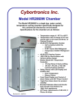
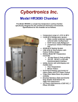
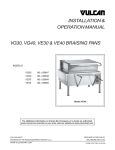
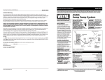
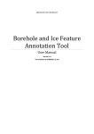
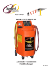
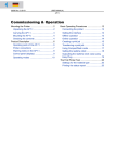
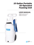
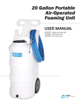
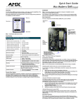
Cybortronics Inc.
Model HR2050 Chamber
Operation
And
Maintenance
Manual
CONFORMS TO
UL STD 61010A-1
CERT. TO CAN/CSA
C22.2 STD NO.1010.1
Operation and Maintenance Manual
PUBLISHED BY:
Cybortronics Inc.
13845-C Alton Parkway
Irvine, CA 92618
Phone: 1-800-289-8203
1-949-855-2814
FAX:
1-949-855-0278
E-Mail: [email protected]
No part of this manual may be reproduced in any form or
by any means, electronic or mechanical (including photocopying), nor may its contents be communicated to a
third party without prior written permission by Cybortronics Inc.
Contents of this manual may change without notice.
Revision Date: January 9, 2004
Page 2
Operation and Maintenance Manual
Table of Contents
Page
SECTION 1
SECTION 2
SECTION 3
SECTION 4
General Information
Safety
Warranty
Packing List
4
5
6
Product theory of Operation
Specifications, Dimensions
and pictorials
Watlow Quick programming Guide
Installation
Electrical Requirements
Wiring Requirements
Electrical Connections
7
9
16
17
Set Up
initial Turn-On
Verification of Controller
Verification of Chamber Functions
Dehumidifier Functions
18
SECTION 5
Calibration
20
SECTION 6
Maintenance
21
SECTION 7
Replacement Parts
24
SECTION 8
Schematics, Drawings
27
Page 3
19
Operation and Maintenance Manual
Chapter 1
GENERAL INFORMATION
Safety
Throughout this manual there are important instructions regarding
the safety considerations. They are focused as follows:
WARNING
Warning denotes a hazard. It calls attention to a
procedure, practice, condition or situation, which if not correctly
performed or adhered to, could result in injury to, or death of personnel.
CAUTION
Caution denotes a hazard. It calls attention to a
procedure, practice, condition or situation, which if not correctly
performed or adhered to, could result in damage to or destruction of part or
all of the product.
CAUTION
Note highlights important information. It calls
attention to an essential procedure, practice, or observation.
Indicates an Electrical Hazard. Improper handling could
cause electrical shock resulting in serious injury or death.
Page 4
Operation and Maintenance Manual
Warranty
•
Cybortronics issues a warranty for this product for the
material and parts for one, (1) year from the date of
shipment.
•
Cybortronics issues a warranty for labor costs for ninety,
(90) days from date of shipment.
•
Cybortronics issues the same warranty for product
shipped overseas, ONLY if a Cybortronics certified service representative witnesses the unpacking, and
installation of the product.
•
Additional warranties, and service contracts are available. Call Cybortronics Inc. and we will be happy to
assist to your service needs.
Page 5
Operation and Maintenance Manual
PACKING LIST
Your Cybortronics Inc. Model HR2050 Chamber, (standard model) has been
shipped from the factory with the following items. Please take an inventory of these
items.
Contact Cybortronics Inc. if any items are missing.
NOTE:
Your chamber may have additional items, please refer to your
purchase order.
1. One, (1) Model HR2050 Cybortronics Environmental Chamber
2. One, (1) Cybortronics Model HR2050 Operation and Maintenance Manual
Consisting of:
a. Watlow Series 988 Communications Manual
b. Munter Dehumidifier Unit Manual
c. Series L Temperature Limit Manual
d. Cybortronics Certification of Conformance/Compliance
e. Watlow Certification of Conformance
3. Four, (4) Adjustable Leveling Feet
4. Three (3) Replacement Condenser Filters
5. Two, (2) Replacement Dehumidifier Filters
6. UUT, (Unit Under Test) Interior Mounting Rack, (standard 19 inch rack rails with
6 support shelf rails.
7. Watlow Series 988 User’s Manual
Page 6
Operation and Maintenance Manual
SECTION 2
PRODUCT THEORY OF OPERATION
AND SPECIFICATIONS
THEORY OF OPERATION
The HR2050 temperature chamber provides an environment in which
electronic manufactured product (unit under test, UUT) can be subjected to
operating temperatures inside and outside normal operating environments. The
temperature chamber takes on the form of a standard electronic equipment
cabinet and features a standard 19” rack rail system to best adapt to the UUT. A
process controller monitors the air in the chamber and controls the functions of air
circulation, heating, cooling, dehumidification, and UUT power control, to induce
and regulate the environment.
BLOWER
High rate air flow is induced through the use of a 1300 CFM ¾ hp blower
that is designed to circulate the air over the UUT and through the temperatureinducing components of the chamber, for rapid and efficient transfer of
temperatures to and from the UUT.
HEATER
A triple element resistive heater of 14 kilowatts is proportionally controlled
through solid-state relays to induce and maintain temperatures rises from –10C to
80 C.
REFRIGERATION
A 3.5 hp R507 based refrigeration system is used to remove the heat from
the chamber and to provide temperatures as low as –10C. The refrigeration
system throttles condensed liquid refrigerant to the evaporator (the cold
component in the refrigeration system) by the temperature controller through the
use of a pulsing solenoid valve. This enables the cooling volume or intensity to be
proportionally delivered to the chamber and UUT.
DEHUMIDIFIER
A desiccant based dehumidifier re-circulates the interior air in the chamber
through a regenerative rotating desiccant wheel to remove moisture from the
Page 7
Operation and Maintenance Manual
interior air and to minimize condensation on the UUT during temperature rises from
freezing.
CONTROLLER
The components of the chamber are controlled via a Watlow 981 process
controller that samples the interior air temperature and regulates the heating,
cooling and dehumidification functions for ramp to, and maintain desired test
temperatures within the chamber. The 981 will operate manually through inputs
from the front panel keypad, from programmed ramp and soak profiles stored in
memory, or through instructions received via it’s standard RS232 communication
port.
A separate and independent Watlow Series L over-temperature controller
monitors the air inside the chamber for conditions above 80C. The controller then
inhibits the UUT power, heating and cooling functions and sounds an Sonalert
alarm in the event these conditions exist. This alarm condition requires a manual
reset by the operator to return the system to normal function.
• Temperature range of –10°C to 80°C
• Temperature rate of change of 5°C per minute with no live load and 50 lbs.
of Fixtured Product
• 50,000 BTU Refrigeration System
• Self contained within the chamber.
• R-507 Ozone Safe Refrigerant
• Compressor Inhibit if Refrigerant lost
• 40,000 BTU Heating System
• 1500 CFM Air Recirculation with “Vertical Airflow” design
• Watlow Model 981 Temperature Controller
• 20 step Ramp & Soak profiling
• RS-232 , RS-422, or EIA 485 Communications Interface
• Safety Alarms with LED Display and Audible alert
• Over-Temperature
• Blower Failure
• Input power phase status
• Front Panel Display and Control of Alarm Status and UUT Power Control
• Double Pane Glass Doors for product visibility
• Brushed Stainless Steel and Granite Grey Powder-Coat Exterior
• AC Power requirements, 208 VAC, 3 Phase, 60 Amps (w/UUT fully loaded)
Page 8
HR2050 Chamber Dimensions
Front View
Page 9
Operation and Maintenance Manual
HR2050 Chamber Front View
UUT Power
Control On-Off
(Optional)
Chamber
Control
Components
under Hood
Watlow
Temperature
Controller
Over-temp Alarm
Reset Switch
User Cable
Pass-thru
Ports
Door `Stay’ Adjust
Page 10
Operation and Maintenance Manual
HR2050 Chamber Rear View
Removable access
cover for Main
Blower and
Cooling Fan
Main AC Input
Disconnect and
Circuit Breaker
UUT/AC
Distribution Panel
P/N 204005
With
6 Fused, Switched
Outlets and
2 User Outlets
Dehumidifier
Temperature
Controller
RS-232
Interface
Dehumidifier
Filters
( Front and Rear )
Main AC Input
Connecter
Dehumidifier
Exhaust Restrictor
Do Not Remove
208 VAC 3 Phase
60 Amps
Condenser Coil
Compressor
Contactor
(behind
compressor)
Condenser Fan
Motor
Removable grills
covering (3)
Condenser
Air Filters
Compressor
Condensate
(rear filter
removed for
visibility)
Page 11
Operation and Maintenance Manual
HR2050 Chamber Dimensions
Footprint
Page 12
Operation and Maintenance Manual
CHAMBER CONTROL PANEL
INDICATES STATUS OF
AC POWER TO POWER
SUPPLY RACK
ALARM INDICATER LED’s
IF LIT, INDICATES ALARM
CONDITION.
(BLOWER ALARM SHOWN)
67
70
INDICATES CHAMBER
+12 VDC POWER
SUPPLY IS
OPERATIONAL.
AC PHASE
ENABLES/ DISABLES
AC POWER TO THE UUT
AC POWER PANEL OR
POWER SUPPLY RACK.
PUSH DOWN TO
RESET THE
OVER-TEMP
ALARM.
MOMENTARY
ACTION.
Page 13
Operation and Maintenance Manual
HR2050 Chamber Dimensions
Side View
Page 14
Operation and Maintenance Manual
CYB20477 AC Distribution Panel
The CYB20477 AC Distribution Panel is an option available in both 115 VAC and 208
VAC single phase versions. This panel provides six (6) fused Switched Outlets. The 6
Switched Outlets are controlled by individual Solid State Relays. Each of these SSR’s
are turned on or off by a connection to the DTR signal line on the RJ-45 interfaces located below the outlets. Two RJ-45’s are provided for each outlet such that an serial
control cable may be `passed thru’ the panel to facilitate the connection to ground
and DTR for the SSR’s. An LED is also attached to each DTR line. The ground line is
passed thru a relay connected to the chamber control circuit. This relay is controlled
via the Power On/Off switch located on the front panel of the chamber. The relay will
also be turned off if an Over-temp alarm condition is present in the chamber. This will
then disable all SSR’s and remove AC power to any product plugged into the 6 UUT
Outlets.
UUT AC
Outlet Circuit
Breaker and
Indicator
UUT AC
Power Outlets
RJ45 UUT
Power Control
Interface
Temperature
Controller
RS-232 Serial
Interface
Page 15
Operation and Maintenance Manual
Watlow Controller Quick Operation Guide
RED DISPLAY
DISPLAY KEY
This display will
normally indicate the
current temperature in
the chamber. It will also
indicate the value of the
parameters displayed
in the GREEN display.
This key will cause the GREEN
display to step thru
displaying the set-point, the
deviation from set-point, the % of
output power, and wether the
temperature is displayed in °C or
in °F.
67
L1 - Indicates that the
heaters are on.
L2 - Indicates that the
cooling system is on.
L3 - Dehumidifier Control
L4 - Indicates that data is
flowing over the RS-232
port.
The 1st press of this key
will enter the SYS menu.
Use up arrow key to step to
PID menu or PROG menu.
See Watlow manual to set
PROG values and steps.
UP and DOWN ARROWS
These keys are normally used to
change the set-point of the
controller. When pressed
simultaneously for approx. 3
seconds, you will enter the setup
mode. Please see the WATLOW
MANUAL.
70
L1 thru L4 DISPLAY
MODE KEY
GREEN
DISPLAY
This display will
normally indicate the
current set-point. It
will also indicate
other functions
depending on the
use of the DISP key
and the MODE key.
Values of these
other functions are
displayed in the
RED display.
RUN / HOLD KEY
Pressing this key once will allow you to
select which of the 4 Ramp and Soak
profiles to run. The RUN Led will flash
at this time. Pressing the key again will
start the
selected profile. The RUN
Led will be on steady while a profile is
running. Ifa profile is running, pressing
this key will stop execution of that
profile and the RUN Led will be off.
Page 16
Operation and Maintenance Manual
SECTION 3
INSTALLATION
SITE SELECTION:
•
Environmental Operating Conditions
Ambient Temperature should be between 6.1°C (43°F) and 29°C (85°F).
Relative Humidity should be no greater than 50%.
•
Flooring should be smooth and level
•
Minimum clearance for the sides and back of the chamber shall be no less than .91
meters, (three feet).
ELECTRICAL CONNECTIONS:
•
208VAC—230 VAC, 50Hz/60Hz,
Three phase, 60 Amps
Take proper precautions when working with
electrical devices.
WARNING! ELECTRICAL SHOCK
HAZARD!
POWER CONNECTION CONFIGURATIONS,
•
Plug, 4 Pole, Wire Grounding—Hubbell Type Plug—Cybortronics P/N 419004
•
•
Mating Connector—Hubbell Type Connector—Cybortronics P/N 405004
CHAMBER EXTERIOR DIMENSIONS:
•
•
•
•
Width— 762 mm, (30 inches)
Depth—1,422 mm, (56 inches)
Height—2,133 mm, (84 inches)
Weight—340 Kg, (750 Lbs.)
Page 17
Operation and Maintenance Manual
SECTION 4
1.
SET-UP, OPERATION AND VERIFICATIONS
•
Set-Up:
Inspect the chamber for shipping damage that may of occurred during transit.
•
Inspect that the filters are in place and that there are not any puncture holes.
•
Verify that the main breaker located on the back of the Chamber is in the “OFF”
position.
•
Connect the power cord.
Take proper precautions when working with electrical
devices.
WARNING! ELECTRICAL SHOCK HAZARD
The Refrigeration compressor is direction critical. Correct phasing
IS REQUIRED.
• The wiring of the power supply drop must match the phasing of the chamber
wiring.
• Wiring of the chamber is as follows: (from the large ground pin moving counterclockwise, looking at the plug)
Large Pin= ground
L1, L2, L3, Neutral, (moving counter-clockwise)
• Observe the Phase Monitor Status LED located on the Control Panel when the
circuit breaker on the chamber is switched on. If the red LED is lit, then the
power supply phasing to the chamber is NOT CORRECT and must be corrected
BEFORE the chamber can function.
• To correct the phasing, at least two of the legs, have to be interchanged.
• MAKE SURE THAT THE CHAMBER IS SWITCHED OFF BEFORE UNPLUGGING THE CHAMBER.
At NO TIME should an attempt be made to change the wiring on the
chamber. Damage to the chamber could result and will void the warranty.
•
Verify that the power cord for the Dehumidifier is plugged into its designated
socket located to the left of the dehumidifier.
•
Verify that the red vent plug on the dehumidifier is not blocked or occluded.
2. Initial Start-Up:
NOTE:
Your Cybortronics Chamber has been extensively tested at Cybortronics before it was packaged and shipped your location. It is advisable to cycle
your chamber to verify all heating and cooling functions are operating properly,
before you load the chamber with your product.
Page 18
Operation and Maintenance Manual
At anytime during this verification procedure your chamber does not function as
prescribed in this procedure, call Cybortronics Inc. (1-800-289-8203) and ask to
speak with a technical service representative.
(When contacting Cybortronics with any service or technical inquiries, please
have your chamber model and serial number available)
3.
•
•
VERFICATION OF TEMPERATURE CONTROLLER, REFRIGERATION
AND HEATER OPERATION
When the circuit breaker is switched to the “ON” position, the chamber
blower will activate and will start to heat or cool the chamber to the temperature set-point on the process controller, (usually 25ºC).
Verify that the chamber will cycle by following the following directions to cycle the chamber to 70°C and down to –10°C.
1.
Press the “↑” arrow keypad while watching the green display and
Ramp the temperature up to 70°. The chamber will now activate the heaters
and start heating. The red display indicates the actual chamber temperature.
2.
The chamber should take approxmately 5 minutes to reach 70°.
3.
At 35°, the Munter Dehumidifier will start. Verify the operation of
the dehumidifier by placing your hand over the red capped exhaust port. A
warm airflow should be exiting from the port.
4.
Now press the “↓” arrow keypad and reduce the temperature
setpoint to –10°, (observing the green display). The chamber will now shut off
the heaters. The refrigeration unit will now start and the temperature in the
chamber will start to drop.
5.
When the chamber has reached –1°,(the red display), the Munter
dehumidifier should shut off. Place your hand in front of the red exhaust port
and you should feel the air flow decreasing to nothing as the blower winds
down, (this may take several seconds for the blower to stop completely).
6. Once the chamber has reached –10°, you may reset the chamber set-point
temperature to 25ºC, (room temp.) or shut the chamber off.
7. If all of the above functions operate properly, your chamber is now ready to
use.
Page 19
Operation and Maintenance Manual
SECTION 5
1.
2.
3.
CALIBRATION:
The Watlow Series 998 Controller is the only device on the Model 2050
Chamber that requires calibration. The Time Delay and the OverTemperature Switch are adjusted at the factory.
a. Cybortronics recommends an annual verification of the Watlow
Controller. Specific Instructions on how to verify the Watlow Controller can
be found on the Watlow Website at: www.watlow.com. Look for the
calibration instructions for the 98X Series Controllers. It has been stated
by Watlow that the calibration procedures are identical for the 98X series
and the 998 Series Controllers.
The Watlow Over Temperature Limit has been set at the factory to alarm at
80ºC, ± 2ºC, (the safe maximum temperature). If the alarm sounds at a
different temperature, contact Cybortronics.
The Time Delay Switch for the refrigeration unit is programmed to shut off
the refrigeration compressor five, (5) minutes after the heating cycle has
started. If the switch seems to be malfunctioning or tripping at a
different time setting, that a replacement be ordered from Cybortronics Inc.
Page 20
Operation and Maintenance Manual
SECTION 5
•
MAINTENANCE:
The HR2050 Temperature Chamber has been designed to provide years of
trouble free operation when periodic maintenance schedules are followed. Adhering to the following periodic maintenance schedule will also keep your chamber within warranty.
Page 21
Operation and Maintenance Manual
Description
Maintenance Schedule
Maintenance Activity
P/N 809002
X
Monthly SemiAnnual
Condenser Filter (s)
Spare holders under the front electrical hood
X
X
X
Restock any spare fuses
Brush or vacuum as necessary
Check all fans for proper operation and direction
Check for Clean Condenser
Condenser Fan Operation
X
Condenser Fan, Heater Fan=counterclockwise (viewing rear of mtrs.)
Dehumidifier Filters (2)
X
Inspect monthly and replace as necessary P/N 809001
Dehumidifier Blower Operation Check that the dehumidifier is working when the L3 Watlow lamp is OFF.
Dessicant Wheel Movement
Check condensate pan and hose for good drainage
Look inside exhaust port to see dessicant wheel moving slowly
X
X
The dehumidifier operates between -1C and +35C. Verify exhaust exiting
from red exhaust port
Check Condensate Hose + Pan
Blower and Condenser Motors
Chamber/Condenser Blower
Operation
Check for Clean Evaporator
Look for discolored lugs, fuses, or relays, under hood
Moving freely, no lubrication required
Good blower air flow/ quiet motor/no vibration
Brush or vacuum as necessary
X
X
X
X
Leave water in copper tube trap to prevent moisture re-entering chamber
Check Electrical Connections
Ramp the chamber to 60C (depedent on UUT mass) (10-12min)HR2050
X
Check Heating Ramp
Annual
Page 22
Operation and Maintenance Manual
Heater Relay and Element
Operation
Maintenance Activity
Dial down overtemp to hear alarm, return to position and
reset @ 80 C
Check heater current while ramping, L1 lamp should be 'on'
solid, Approx. 30 Amps under load @ contact #2 of SSRs
(3 of them)
Description
X
X
X
Maintenance Schedule
Overtemp Alarm
Inside, back wall, in discharge. Gently push switch up, listen for alarm. Then reset on front panel
X
Semi-Annual
Blower Alarm
230 Volts, MAX. 3 Phase, check at control panel under
hood at L1, L2, L3
X
Monthly
Measure Input Voltages
Inspect Refrigeration, check for leaks, Check run current,
6.5 Amps
X
Check Refrigeration Operation
Check oil sight glass in compressor for proper level.
HR2050=10min ±2 minutes
Check Compressor Oil
Level
Verify correct reading by sampling at the chambers thermocouple
Performance 60-0 C
Temperature Control Verification
location, inside and just above door jamb. +/-2 degrees C
Annual
X
Page 23
Operation and Maintenance Manual
SECTION 7
RECOMMENDED SPARE/REPLACEMENT
PARTS
Cybortronics has included in this manual a comprehensive replacement and spare
parts list. Refer to your maintenance schedule in this manual for replacement
frequency.
Items marked by an asterisk indicate that the replacement and spare parts should
be added to your current inventory to reduce downtime.
Contact Cybortronics Inc. at: 1-949-855-2814. A Customer Service Representative will process your order. All orders are shipped F.O.B., Irvine California, USA.
Page 24
Operation and Maintenance Manual
CHAMBER MODEL HR2050 REPLACEMENT PARTS MATRIX
** Recommended on Hand
Description
Location
Part Number
Blower Motor
Top Air Box
412001
Blower Sub-Assembly
Top Air Box
204003
Capacitor, Blower Motor
Top Air Box
411001
Cooling Fan, Blower Motor
Top Air Box
608001
Fan, Condenser
Lower Refrigeration Area
419001
Dehumidifier Control Relay
Main Electrical Panel
402001
Heater Assembly
Top Air Box
204004
Fuse, 5 Amp
Main Electrical Panel
407001*
Fuse, 8 Amp
Main Electrical Panel
407002*
Fuse, 10 Amp
Main Electrical Panel
407003*
Fuse 15 Amp
Main Electrical Panel
407004*
Fuse 15 Amp
Main Electrical Panel
407005*
Fuse 25 Amp
Main Electrical Panel
407006*
Fuse 30 Amp
Main Electrical Panel
407007*
Fuse 40 Amp
Main Electrical Panel
407008*
Solid State Relay, 25Amp
Main Electrical Panel
507003*
Solid State Relay, 75A
Main Electrical Panel
507002*
Solid State Off Delay Timer
Main Electrical Panel
513001
Process Controller
Front Control Panel
418001*
Overtemp Controller
Front Control Panel
418002*
Power Supply, 12V
Main Electrical Panel
202001
Line Phase Moniter
Main Electrical Panel
419002
Fan Switch Assembly
Inside Chamber on Back Wall
204001
Fan Speed Control Unit
Refrigeration Control Box
416001
Main Circuit Breaker 60 Amp
Back Upper Panel
410001*
Dehumidifier Unit
Back of Chamber
204002
Relay, Main Control Board
PCB, Front Control Panel
402004
Refrigeration Contactor
Refrigeration Control Box
606001*
Dehumidifier Filter
Dehumidifier
809001*
Air Filters (12 per case)
Around Refrigeration System
809002*
Low Pressure Limit Switch
(5/20)
Lower Refrigeration Area
606002
Page 25
CHAMBER MODEL HR2050 REPLACEMENT
PARTS
MATRIX, CONT.
Operation and
Maintenance
Manual
Dehumidifier Filter
Dehumidifier
Air Filters (12 per case)
Around Refrigeration System
Low Pressure Limit Switch (5/20)
Lower Refrigeration Area
High Pressure Limit Switch (425/500)
Lower Refrigeration Area
Solenoid Valve
Lower Refrigeration Area
TXV Orifice Cartridge (for Main Expasion Valve Kit)
Lower Refrigeration Area
Main TXV Body (for Main Expasion Valve Kit) Lower Refrigeration Area
Dryer/Filter
Lower Refrigeration Area
Compressor
Lower Refrigeration Area
Refrigerant
Refrigeration System
UUT Panel
Outlet Control Relay
Main Electrical Panel
809001*
809002*
606002
606003
607001
608004
207001
608002
604002
608005
507003*
Revised 12/11//03
Page 26
Operation and Maintenance Manual
SECTION 8
Drawings and Schematics
Page 27
8
7
PHASE 3
To Fuses on
Main Control
Panel
6
5
4
3
2
1
F9
PHASE 2
F8
PHASE 1
F7
D
D
GROUND
1
J1
2
3
4
5
6
CB1
CB2
CB3
CB4
CB5
CB6
5A
5A
5A
5A
5A
5A
1
2
3
4
5
6
C
C
6 PIN MOLEX
SSR-25
-
SSR-25
+
-
SSR-25
+
-
SSR-25
+
-
SSR-25
+
-
SSR-25
+
-
+
K1
4
8
B
B
16
1
2
3
4
5
6
7
8
1
RELAY DPDT
RJ-45 IN
1
2
3
4
5
6
7
8
1
2
3
4
5
6
7
8
RJ-45 OUT
RJ-45 IN
1K
1K
1
2
3
4
5
6
7
8
RJ-45 OUT
1
2
3
4
5
6
7
8
RJ-45 IN
1K
1
2
3
4
5
6
7
8
RJ-45 OUT
1
2
3
4
5
6
7
8
1
2
3
4
5
6
7
8
RJ-45 IN
1K
RJ-45 OUT
1
2
3
4
5
6
7
8
1
2
3
4
5
6
7
8
RJ-45 IN
1
2
3
4
5
6
7
8
RJ-45 OUT
1
2
3
4
5
6
7
8
RJ-45 IN
1K
RJ-45 OUT
1K
A
A
CYBORTRONICS INC.
IRVINE, CALIF.
Title
AC DISTRIBUTION PANEL
Size
B
Date:
8
7
6
5
4
3
Document Number
Rev
CYB20440-208-SCH
Tuesday, October 28, 2003
2
C
Sheet
of
1
1
2
3
4
5
6
F13 TRM25
PHASE 3
7
COMPRESSOR
F12 TRM25
Blue
Condenser
CS1
8
A
PHASE 2
Red
MAIN
POWER
INPUT
3
L1
4
L2
5
L3
4KW Heater
CS2
Hi Side Pres.
2
4KW Heater
4KW Heater
Fan Motor
F11 TRM25
3 Phase
Line Monitor
8
Low Side Pres.
A
K2
Compressor
Solenoid
1
Bypass
Solenoid
LED On When Phase OK
A3T40
A3T40
-
AC AC com no nc
OVERTEMP
TRM8
CONTROL
F5
80
+
2
1
2
AC
AC
AC
SSR3
SSR-75A
SSR3
SSR-75A
-
+
-
+
-
+
RELAY
K3
3
F15
TRM8
4
F14
GROUND
AC
3
AC
SSR1
SSR-40A
AC
SSR4
SSR-75A
4
AC
AC
3
2
60 AMPS
1
NEUTRAL
1
3 PHASE
A3T40
4
FA
2
FB
208 VAC
3
FC
1
F4 AGC5
Black
4
PHASE 1
AGC5
B
B
SET
P1
BLWR
15A
BLOWER
+
Load
`T'
LS1
Control Line
Plug
sw
Power Pack
-
MAIN
sw
12 VDC
TC+ TC- SW SW
F1
1
2
Off Delay Timer
SWITCH
Dehumidifier
Line
F10 AGC10
RELAY
K1
Dehumidifier AC
+
F2
15A
Distribution
Panel
F7
15A
CYB20477A
F8
To Optional AC
SONALERT
F9
11
2
3
15A
13
14
15A
16
17
J2
14
13
12
11
10
9
8
7
6
5
4
3
2
1
J1
23
RJ-45
TEMP
CONTROL
5
6
7
9
C
RS-232 to
CPU
22
WATLOW
TxD
RxD
GND
10
1
-
D2
C
`T' Type
+
2
D1
JP1
1
2
3
4
5
6
7
8
Thermocouple
3
4
6
6
4
4
6
4
8
8
8
11
11
13
13
11
13
9
9
16
1
16
K3
K1
PWR
ON
S1
5
6
PWR ON/OFF
7
AUDIBLE RESET (Mom.)
BLWR
ALM
PHZ
ALM
OT
ALM
SYS
PWR
9
16
1
K2
S2
1
FRONT PANEL
LED'S AND SWITCHES
8
CYB20480 MODULE Rev. B
On/Off Control for External Device
D
Figure 1.1
Cable on rear of Chamber
D
J3
1
2
3
4
5
6
Switched Ground
By Power On/Off Switch
Cybortronics Inc.
13845-C Alton Pkwy
Irvine, CA 92618
1-800-289-8203
Switched +12 VDC
By Alarm Condition
Title
HR-2050 MAIN CONTROL SCHEMATIC
6 PIN MOLEX
Size
Document Number
Custom
CYB2050-SCH
Date:
1
2
3
4
5
6
7
Thursday, February 05, 2009
Rev
H
1
Sheet
8
of
1