1
Master Thesis
Sebastian Hoop
Semantic Preserving Transformations from
ATLAS Testcase Descriptions to Teststand
Sequences
June 4, 2015
supervised by:
Prof. Dr. S. Schupp
Prof. Dr. R. God
Dipl.-Ing. A. Wichmann
F. Sell
Hamburg University of Technology (TUHH)
Technische Universität Hamburg-Harburg
Institute for Software Systems
21073 Hamburg
Eidesstattliche Erklärung
Ich, SEBASTIAN HOOP (Student im Studiengang Informationstechnologie an der
Technischen Universität Hamburg-Harburg, Matr.-Nr. 20730088), versichere, dass ich
die vorliegende Masterarbeit selbständig verfasst und keine anderen als die angegebenen Hilfsmittel verwendet habe. Die Arbeit wurde in dieser oder ähnlicher Form noch
keiner Prüfungskomission vorgelegt.
Ort, Datum
Unterschrift
ii
Contents
Contents
1 Introduction
1.1 Motivation . . . . . . . . . . . . . . . . . . . . . . . . . . . . . . . . .
1.2 General Approach . . . . . . . . . . . . . . . . . . . . . . . . . . . . .
1.3 Goals . . . . . . . . . . . . . . . . . . . . . . . . . . . . . . . . . . . .
2 Transforming Languages
2.1 Compiler Construction . . . . . . . . .
2.1.1 Main Compilation Phases . . .
2.1.2 Context-free Grammars . . . .
2.2 Source Transformation tools . . . . . .
2.2.1 The Turing eXtender Language
2.2.2 Additional parsing techniques .
2.2.3 More Transformation Tools . .
1
1
1
2
.
.
.
.
.
.
.
4
4
4
5
7
7
10
11
3 Test Language Transformation
3.1 Test Software for Automatic Testing . . . . . . . . . . . . . . . . . . .
3.1.1 ATLAS: The Language for all Systems . . . . . . . . . . . . . .
3.1.2 TestStand: The Industry-Standard Test Management Software
3.1.3 Automatic test environments . . . . . . . . . . . . . . . . . . .
3.2 Requirements on the Translator . . . . . . . . . . . . . . . . . . . . . .
3.2.1 Parsing ATLAS Syntax . . . . . . . . . . . . . . . . . . . . . .
3.2.2 Preserving Semantics in Avionic Environments . . . . . . . . .
13
13
13
18
21
21
22
23
4 The Translator
4.1 Transformations . . . . . . . . . . .
4.1.1 Preamble . . . . . . . . . . .
4.1.2 Flow control . . . . . . . . .
4.1.3 Data Processing . . . . . . .
4.1.4 Hardware Control Statements
4.1.5 Expressions . . . . . . . . . .
4.2 Teststand Assembler . . . . . . . . .
4.2.1 Concept . . . . . . . . . . . .
4.2.2 Construction Examples . . .
.
.
.
.
.
.
.
.
.
25
26
27
32
37
38
40
41
42
46
.
.
.
.
49
49
50
51
52
5 Evaluation
5.1 Applicability .
5.2 Case Study . .
5.2.1 Limits .
5.2.2 Runtests
.
.
.
.
.
.
.
.
.
.
.
.
.
.
.
.
.
.
.
.
.
.
.
.
.
.
.
.
.
.
.
.
.
.
.
.
.
.
.
.
iii
.
.
.
.
.
.
.
.
.
.
.
.
.
.
.
.
.
.
.
.
.
.
.
.
.
.
.
.
.
.
.
.
.
.
.
.
.
.
.
.
.
.
.
.
.
.
.
.
.
.
.
.
.
.
.
.
.
.
.
.
.
.
.
.
.
.
.
.
.
.
.
.
.
.
.
.
.
.
.
.
.
.
.
.
.
.
.
.
.
.
.
.
.
.
.
.
.
.
.
.
.
.
.
.
.
.
.
.
.
.
.
.
.
.
.
.
.
.
.
.
.
.
.
.
.
.
.
.
.
.
.
.
.
.
.
.
.
.
.
.
.
.
.
.
.
.
.
.
.
.
.
.
.
.
.
.
.
.
.
.
.
.
.
.
.
.
.
.
.
.
.
.
.
.
.
.
.
.
.
.
.
.
.
.
.
.
.
.
.
.
.
.
.
.
.
.
.
.
.
.
.
.
.
.
.
.
.
.
.
.
.
.
.
.
.
.
.
.
.
.
.
.
.
.
.
.
.
.
.
.
.
.
.
.
.
.
.
.
.
.
.
.
.
.
.
.
.
.
.
.
.
.
.
.
.
.
.
.
.
.
.
.
.
.
.
.
.
.
.
.
.
.
.
.
.
.
.
.
.
.
.
.
.
.
.
.
.
.
.
.
.
.
.
.
.
.
.
.
.
.
.
.
.
.
.
.
.
.
.
.
.
.
.
.
.
.
.
.
.
.
.
.
.
.
.
.
.
.
.
.
.
.
.
.
.
.
.
.
.
.
.
.
.
.
.
.
.
.
.
.
.
.
.
.
.
.
.
.
.
.
.
Contents
6 Conclusion
6.1 Future Work . . . . . . . . . . . . . . . . . . . . . . . . . . . . . . . .
iv
55
57
Acronyms
Acronyms
AEEC Airlines Electronic Engeneering Committe
API Application Programming Interface
ARINC Aeronautical Radio Inc
ATE Automatic Test Enviroments
ATLAS Abbreviated Test Language for All Systems
CMM Component Maintenance Manual
GUI Graphical User Interface
IEEE Institute of Electrical and Electronics Engineers
LHT Lufthansa Technik AG
NI National Instruments
OEM Original Equipment Manufacturer
TSN Test Step Number
TUA Test Unit Adapter
TXL Turin eXtender Language
UUT Unit Under Test
v
List of Figures
List of Figures
1.1
Basic source transformation concept . . . . . . . . . . . . . . . . . . .
2
2.1
TXL Processor . . . . . . . . . . . . . . . . . . . . . . . . . . . . . . .
8
3.1
3.2
3.3
3.4
3.5
Standard ATLAS Statement Structure . . . . . . . . . . . . . . . . .
ATLAS Program Structure . . . . . . . . . . . . . . . . . . . . . . .
ATLAS Preamble Structure . . . . . . . . . . . . . . . . . . . . . . .
ATLAS Procedural Structure . . . . . . . . . . . . . . . . . . . . . .
TestStand System Architecture from TestStand User Manual[9, 1-4]
.
.
.
.
.
14
14
15
17
18
4.1
4.2
Transformation Concept . . . . . . . . . . . . . . . . . . . . . . . . . .
ATLAS Procedures . . . . . . . . . . . . . . . . . . . . . . . . . . . . .
25
30
5.1
5.2
5.3
Interchanged Limits . . . . . . . . . . . . . . . . . . . . . . . . . . . .
Incorrect Variable Monitoring . . . . . . . . . . . . . . . . . . . . . . .
Hardware Timing Problem . . . . . . . . . . . . . . . . . . . . . . . . .
51
53
54
vi
1 Introduction
1 Introduction
This work transforms ATLAS test cases to TestStand sequences using TXL. In consideration of preserving the semantics the test software is migrated into TestStand
using robust parsing techniques and the method is evaluated by means of a case study.
1.1 Motivation
All modern aircraft types consist of many electronic flight computers, a Fly-By-Wire
system. The aircraft manufacturer like Airbus and Boeing are subcontracting the
development and production of these components, so an airline has to deal with lots
of companies for the maintenance. In this market segment Maintenance, Repair and
Overhaul (MRO) companies like Lufthansa Technik AG (LHT) provide a complete
maintenance solution for all aircraft components for airlines.
To repair and certify a flight component a test according to the manufacturer specification is mandatory. Historically the test specification is often provided as Abbreviated Test Language for All Systems (ATLAS). The development of the test language
ATLAS started in 1967. The purpose of the original version (ARINC Specification
416) was an application and documentation language for manual and automatic testing of airline avionics. It was designed to describe both, the test procedure and the
needed hardware resources in a way that engineers could simply understand the instructions with no room for misunderstanding.
Nowadays it became more and more an ineffective way to host this old language
to modern measurement instruments. Due to the slow execution speed and the fact,
that ATLAS does not support digital bus systems, changes the way testing of digital
flight computers is implemented. But a manually programmed test program is very
cost intensive.
1.2 General Approach
To make it possible to use the ATLAS test specifications we need to develop a method
to convert the ATLAS source code into TestStand, an up to date programming language. The general approach in this work is source to source transformation. The
requirements on such a transformation are very high. Especially in avionic systems
preserving semantics is very important to approve safety and governmental restrictions, among others. This means we need a robust and reliable transformation system.
Figure 1.1 illustrates the basic concept of the transformation approach. The process
can be divided into 4 different phases:
1
1 Introduction
Figure 1.1: Basic source transformation concept
Parsing
The parsing phase is very similar to parsing done in a compiler[1]. A formal structure
in form of a grammar is introduced to describe the ATLAS language and parse it
into a tree structure for later transformation. It is important to build the grammar
as precise as possible to avoid ambiguity and prevent syntax failures. Thereby the
balance between a precise grammar and effective transformation rules already need
to be considered. The larger a grammar grows, the more complicated it is to develop
transformation rules later on. The solution to this task are robust parsing techniques
and island grammars.
Transformation
In the next phase transformation rules are applied to the parse tree. A direct transformation to the target language is not possible because TestStand sequence files are
stored in a proprietary binary format. So the parse tree is migrated into a structure describing macros for TestStand sequence building. Therefore, a grammar that
describes the TestStand macros is necessary. Because of the lack of formal semantic definitions of ATLAS and TestStand, there is no formal method of proofing the
semantics of the transformed source code correct, so we need to look at each transformation rule individually.
Unparse and Assemble
In the unparse phase the parse tree is assembled to an intermediate code that consist
of simple commands for construction of the final sequence files. We call this code
TestStand macros. In the assemble phase these macros are then read by a program,
the TestStand macro assembler, that is capable of constructing the TestStand sequence file.
1.3 Goals
The goal of the thesis is to develop a robust transformation system that is capable
of migrating ATLAS source code into running TestStand sequences. The transformations as correct as possible by observing each transformation rule individually and by
comparing the output a transformed program produces with the output of the source
2
1 Introduction
program.
This leads to the following contributions:
• Semantics
– Identify relevant means to describe and compare semantics.
– Develop a robust grammar to specify Original Equipment Manufacturer
(OEM) Software syntax.
– Introduce rules to transform one high level language into the other.
• Tool
– Construct an assembler program to produce the binary sequence file of the
new system.
– Design a grammar/pseudo language that can be read by the assembler
program.
• Evaluation
– Test the transformation system on different inputs and compare the results.
– Evaluate the output of one case study by comparing the results of both
programs.
3
2 Transforming Languages
2 Transforming Languages
In this chapter, the techniques of source transformation are introduced. The typical
application for source transformation is a compiler. In section 2.1 the basics of compiler construction are explained and the techniques and tools that are useful for this
work are introduced.
2.1 Compiler Construction
Simply stated, a compiler is a program that can read a program in one language - the source language - and translate it into an equivalent program
in another language - the target language[1]
Usually the target language for compilers is a low level language like Assembler or
even machine language. In this work, the source and the target language are high
level development languages, but the basic principles are the same so the techniques
of compiler construction can be adopted.
2.1.1 Main Compilation Phases
In general the work flow of a compiler can be divided into multiple phases. In the
following the major parts are illustrated:
• Lexical analysis: A Lexer reads the high level source code and chops its characters into meaningful tokens.
• Syntax analysis: A Parser reads this string of tokens and groups them into a
parse tree.
• Semantic analysis: A code generator converts the parse tree into a list of
machine instructions
Theses steps can also be found in source to source transformation. The key components are a well defined parser grammar and a code generator that does not violate
the semantics of the source program. Many compilers also have the ability to identify
and correct syntax failures or optimize the code. This is out of the scope of this work
but might be a possibility for future work.
Syntax analysis
There are two ways to describe a programming language. The first way is to describe
its semantics. What each program does when its being executed. The second way
4
2 Transforming Languages
is to describe the proper form of a programming language, the syntax. Contex-free
grammars or Backus-Naur-Form (BNF) are widely used to specify the syntax of a
programming language.
2.1.2 Context-free Grammars
A context-free grammar basically consists of four components:
1. A set of fundamental symbols of the language defined by the grammar. These
symbols are called terminal symbols, or tokens.
2. A set of non-terminals, that each represent a set of strings of terminals.
3. One of the non-terminals assigned to be a start symbol.
4. A set of productions that each consist of a head (a non-terminal) and the body
of the production (a sequence of terminals and/or non-terminals). Productions
specify the manner in which the terminals and non-terminals can be combined
to form strings.
The pictorial representation of how the start symbol of a grammar derives a string
in the language, is a parse tree. If a non-terminal X has a production ABC, the
parse tree would have an interior node named X and three children from left to right
named A, B, and C.
Formally a parse tree according to a context-free grammar is a tree with the following properties, given that is an empty string:
1. The root is designated by the start symbol.
2. Each leaf is designated by a terminal or by .
3. Each interior node is designated by a non-terminal.
4. If the non-terminal X is designated by some interior node and X1 , X2 , ..., Xn
are the labels of the children of that node from left to right, then there must
be a production X → X1 X2 ...Xn . X1 X2 ...Xn can either be a terminal or a
non-terminal. If X → is a production, than a node designated by X may have
a single child designated by .
If a grammar has more than one parse tree generating a given string of terminals,
it is said to be ambiguous. This is shown by finding a terminal sting that is the yield
of more than one parse tree.
So an unambiguous grammars for compiling applications need to be designed, or
an ambiguous grammars with additional rules to resolve the ambiguities to be used,
since a string with more then one parse tree usually has more than one meaning.
5
2 Transforming Languages
From the parse tree view point, there are two major parsing techniques to consider.
It is convenient to describe parsing as the process of building parse trees, although
a front end may in fact carry out a translation directly without building an explicit
tree.
Top-down parsing
Top-down parsing constructs the parse tree for the input string starting from the
root and developing the nodes depth-first. Alternatively, top-down parsing can also
be seen as finding a leftmost derivation for an input string. The key problem for each
step of a top-down parse is that of determining the production to be applied for a
non-terminal. For example using the general recursive-descent parsing approach. If
a production for non-terminal X is chosen, the rest of the parsing process consists of
matching the terminal symbols in the production body with the input string. If the
input string doesn’t match, backtracking might be required.
Predictive parsing is a special case of recursive-descent parsing. The correct Xproduction is chosen, by looking ahead at the input a fixed number of symbols. This
class of grammars is sometimes called LL(k) class, where k is the number of symbols
the parser in looking ahead.
Bottom-up parsing
Bottom-up parsing is approaching the problem, as the name may reveal, from the
other way around. The construction begins at the leaves and is working up towards
the root. This process man also be seen as reducing a string β to the start symbol of
the grammar. This means at each reduction step, a non-terminal at the head of the
production replaces a specific substring matching the body.
One form of bottom-up parsing is shift-reduced parsing. A stack holds the grammar
symbols and an input buffer holds the rest of the string. The parser, than does a
left-to-right scan, where it shifts zero or more input symbols onto the stack, until it is
ready to reduce a string β of grammar symbols on top of the stack. β is then reduced
to the head of the appropriate production. This cycle is repeated until the stack contains the start symbol and the input is empty, or until the parser has detected an error.
This leads to four possible actions a shift-reduce parser can make:
1. Shift: The next input symbol is shifted onto the top of the stack.
2. Reduce: Reduce the right end of the string that must be at the top of the stack.
Decide with what non-terminal to replace the string that is located on the left
end of the string within the stack.
3. Accept: Parsing has been completed successfully.
4. Error: A syntax error has been discovered. Call an error recovery routine.
6
2 Transforming Languages
The largest class of grammars for which shift-reduce parsers can be built, are called
LR grammars.
2.2 Source Transformation tools
2.2.1 The Turing eXtender Language
The original purpose of the Turin eXtender Language (TXL) in the early 1980’s was
to stretch the Turing programming language to include new language features. The
developers focused on true rapid prototyping with no generation or build steps. This
led to the decision to choose the functional programming language Lisp [11] as the
model for the underlying semantics of TXL because of the following reasons:
• One simple data structure - nested first-rest lists.
• Fast interpretive full backtracking implementation, well suited for rapid prototyping.
• Implementation is heavily optimised for list processing.
Therefore Lisp structures provide the foundation for many design decisions of TXL
early on. This leads to a parsing model with a top-down functional interpretation
of the grammar. The start symbol is the non-terminal [program]. The grammar is
directly interpreted as a recursive functional program that is consuming the input as
a list of terminal symbols. The structure of each TXL grammar consists of two kinds
of lists:
1. A choice list for alternation.
2. An order list for sequencing.
The interpretation of alternate form in choice lists is the order they are presented in
the grammar. The first matching alternative is taken as a success. The representation
in lists highly favours backtracking while parsing. If a choice alternative or sequence
element is failing, the algorithm simply backtracks one element of the list to try the
next alternate form. At the end, the result is a parse tree, that is represented in the
same nested list representation, like every TXL structure (grammar, parse tree, rules,
patterns and replacements). TXL also addresses the difficulties with left recursion in
top-down parses, by switching to a bottom-up interpretation of these productions on
the fly.
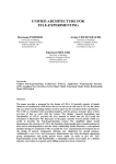
Figure 2.1 illustrates the the compiler and run time system for the TXL language.
The TXL processor directly interprets the TXL programs that are consisting of the
grammar and the transformation rules and functions.
7
2 Transforming Languages
Figure 2.1: TXL Processor
The grammar
The Source language to be transformed is described using an unrestricted ambiguous
context-free grammar in extended Backus-Naur-Form (BNF), from which a structure
parser is automatically derived. The basic notation is as follows:
• X: terminal symbols represent themselves
• [X]: non-terminal types appear in brackets
• |: the bar separates alternative syntactic forms
Listing 2.1 shows an example TXL grammar. The key unit is the define statement. Each define statement represents an ordered set of alternative forms for one
non-terminal. This set can be compared with a set of productions for a single nonterminal in a BNF grammar. Each alternative form is specified as a sequence of
terminal symbols and non-terminals. In case of the example grammar the terminals
shown are: +,-.*,/,(,). The non-terminal [number] in line 18 is a special predefined
non-terminal representing any "unsigned integer or real number beginning with a digit
and continuing with any number of digits, an optional decimal point followed by at
least one more digit, and an optional exponent beginning with the letter E or e and
followed by an optional sign and at least one digit."[7, 4]
Listing 2.1: Simple Example Grammar from TXL Cookbook [6]
1 define program
2
[ expression ]
3 end define
4
5 define e x p r e s s i o n
6
[ term ]
8
2 Transforming Languages
7
8
9
10
11
12
13
14
15
16
17
18
19
20
|
[ e x p r e s s i o n ] + [ term ]
|
[ e x p r e s s i o n ] − [ term ]
end define
define term
[ primary ]
|
[ term ] ∗ [ primary ]
|
[ term ] / [ primary ]
end define
define primary
[ number ]
|
( [ expression ] )
end define
Rules and functions
After parsing the source language into a parse tree according to the explained grammar, the rules and functions that are responsible for transforming the input parse tree
into the output parse tree are applied. The difference between a rule and a function
is, that a rule searches the scope of the tree it is applied to for matches to its pattern
and replaces every match, where a function just replaces the first match.
Listing 2.2: Simple Example Rule from TXL Cookbook [6]
1
2
3
4
5
6
rule addOnePlusOne
replace [ e x p r e s s i o n ]
1+1
by
2
end rule
% name
% t a r g e t type to search for
% p a t t e r n t o match
% r e p l a c e m e n t t o make
The Listing 2.2 illustrates a simple example rule. Every rule/function consists of a
name (line 1), a type (line 2), a pattern (line 3) and a replacement(line 5). The name
serves as identifier and the type is the non-terminal that the rule/function transforms.
If the argument tree of the rule/function matches the pattern, the replacement is the
result of the rule/function (In this case "2"). If the argument tree doesn’t match, the
result is the same tree again ("1+2" for example).
Every TXL function is homomorphic and total, because they always return a tree
of the same type as their argument to guarantee, that the transformation of an input
always results in a well-formed output according to the defined grammar. They also
always return the original tree if it does not match the pattern, so they produce a
9
2 Transforming Languages
result for any argument of the appropriate type.
2.2.2 Additional parsing techniques
When using TXL as a source to source transformation tool, some parsing techniques
might be useful to implement. In section 3.2.1 the need for a specialisation on certain
recurring parts of the ATLAS source language is discussed. This means a parser is
needed, that accepts unknown statements and transforms them properly. The techniques to achieve that functionality are presented in this section. The implementation
of these techniques are shown in chapter 4.
Robust Parsing
The general strategy of robust parsing was originally proposed by David Barnard
[2] and is based on the observation that the syntax of programming languages are
basically all structured into statements. These statements often have an explicit end
marker like the semicolon in Java or C and the period in Cobol. This observation
leads to a very effective way of syntax error handling and repair strategy.
This strategy can be described in a few steps:
1. A special recovery state is entered, every time a syntax error is detected.
2. Parsing is then continued in recovery state and the input is treated as if every
token matches but actually is not accepted. This leads to a valid parse of a
program that is slightly different from the original input.
3. Continue until the expected input token is a statement end marker. The actual
input is then flushed to this marker, the recovery state can be exited and normal
parsing continues. The flushed input can later be caught by a syntax error
routine, that prompts a warning for instance.
This technique can be used to accept every ATLAS input program while just transforming the parts that are actually implemented.
Island Grammars
Island grammars implement the basic idea of robust parsing. In software analysis
island grammars are used for example in source model extraction [12] or when building
documentation generators[8]. An island grammar simply consists of the following
parts:
1. Detailed productions for the parts of the language that are of interest.
2. Liberal productions that are catching the remaining parts.
3. An elementary set of definitions that cover the overall program structure.
10
2 Transforming Languages
General speaking an island grammar consist of constructs of interest (the islands)
and parts that are not interesting for the developer (the water).
Union Grammars
Unlike the language extension tasks for which TXL was designed, source to source
transformation requires transformations to deal with two language grammars - the
source language (ATLAS) and the target language (TestStand). Hence TXL rules
are constrained to be homomorphic, it could be problematic to solve this kind of
multi-grammar task.
The solution is union grammars. The basic paradigm for union grammars involves
the following steps:
1. Create working grammars for both the target and the source language.
2. Uniquely rename the non-terminals of the two grammars.
3. Identify a minimal set of corresponding non-terminals to be used as transformation targets.
4. Restructure and integrate the source and target grammars to form an integrated
translation grammar.
5. Build a set of independent translation rules for each corresponding non-terminal
2.2.3 More Transformation Tools
Source transformation is a great field of research. Although there are a lot of source
transformation tools, most of them are not designed to migrate two languages, but
they are still good to meet this task. In the following few of them are presented.
Many other source transformation tools and languages can be found on the program
transformation wiki, http://www.program-transformation.org.
Stratego
Stratego[13] is a modern language aimed at the specification of program transformation systems based on the paradigm of rewriting strategies. Stratego adapted an idea
from Elan[3] deduction meta system and uses pure rewriting rules with the separate
specification of generic rewriting. This separation allows careful control over the application of these rules and allows transformations rules to be reusable in multiple
different transformations. It also lead to a more compact and modular transformation
specification compared to TXL.
11
2 Transforming Languages
ASF + SDF
ASF+SDF [4] is a toolset for implementing many programming language manipulation tools like parsers and transformers, that is very different from TXL in its methods and implementation. It uses a GLR parsing algorithm providing grammar-based
modularity and supports the specification of patterns in concrete syntax
12
3 Test Language Transformation
3 Test Language Transformation
3.1 Test Software for Automatic Testing
This section introduces the source and target language and presents the environment
they are usually used in.
3.1.1 ATLAS: The Language for all Systems
The ATLAS test language was developed by the Aeronautical Radio Inc (ARINC)
to satify the desire for an application and documentation language for manual and
automatic testing in airline avionics. The Development started in 1967 by the Automatic Test Equipment Subcommitee of the Airlines Electronic Engeneering Committee (AEEC). In June 1969 ARINC published the first version of ARINC Specification
416 titled Abbreviated Test Language for Avionics Systems (ATLAS).
Because of the increasing interest on ATLAS for potential applications in industrial
and military testing, the amount of applications in other areas was growing so fast,
so that AEEC authorised the transfer of ATLAS to IEEE. IEEE Std. 416-1976 titled IEEE/ARINC Standard ATLAS Test Language was published in November 1976.
The further development of the avionics system for new aircraft lead to several
new versions and revisions until in March 1987 the ARINC Specification 626, titled
Standard ATLAS Language for Modular Test, was published. ARINC Specification 626-3[5], that was published in January 1995, is the most recent release and
the version that is used in this work.
The main features of ATLAS are the Unit Under Test (UUT) orientation, the unambiguous communication and the test equipment independence. The language is
suited to define the requirements of the UUT without creating dependencies to specific test equipment. To ensure an unambiguous description of the requirements of a
test procedure for the UUT designers, developers, users and maintenance technicians,
the description of test requirements and formal structures are defined precisely. Furthermore the description of the test requirements is designed to transport the test
specification from implementation on one set of test equipment to another.
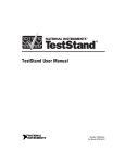
The ATLAS program structure basically consists of variables and statement syntax. A standard ATLAS statement consists of a flag field(F), statement number field
(STATNO), verb field (VERB), field separator(,), statement remainder (REMAINDER) and statement terminator($) arranged in Figure 3.1
Figure 3.2 illustrates the standard ATLAS program structure. Every ATLAS program starts with a begin atlas statement and ends with a terminate atlas statement.
13
3 Test Language Transformation
Figure 3.1: Standard ATLAS Statement Structure
The commence main procedure statement separates the two main elements: program
preamble structure and main procedural structure.
Figure 3.2: ATLAS Program Structure
The program preamble structure consists of statements that do not cause any tests
to be executed, but the information contained in the structure is used by the statements in the main procedural part. Figure 3.3 on page 15 illustrates all ATLAS
preamble statements defined in the ARINC Specification 626-3 [5]. In the following
these statements are briefly described.
Include statements reference to ATLAS modules that may be used in multiple test
programs. These modules contain non ATLAS code, that may be loaded into a UUT,
or often used preamble statements. They don’t contain any procedural statements
with the exception of procedures and functions.
Extend statements provide means to add supplementary definitions for signal and
for bus parameters, protocol parameters, bus modes and test equipment roles to the
ATLAS language.
Require statements describe and label the requirements on different hardware resources. These test resources are termed "virtual resources" and represent a link
between the test software and the "real resources". The checking and assignment of
"virtual resources" to "real resources" is a complex implementation problem which is
outside the scope of this work.
Declare statements establish, label and identify data types, constants and variables.
Establish statements specify a bus protocol for later use with do exchange statements.
Define statements establish and label parts of the test software which are not executed until the label is mentioned direct or indirect in a subsequent procedural statement. The procedure and function structure contain ATLAS procedural statements,
that are often used in the program flow.
Identify statements label and describe events that allow the establishment and implementation of signal and test action timing relationships.
14
Event interval
Event indicator
Time based
event
Function
Exchange Configuration
Digital Configuration
Load
Timer
Databus
15
Figure 3.3: ATLAS Preamble Structure
Variable
Exchange
Procedure
Event
Signal
Source
Signal
Timer
Identify statement
Modifier
Type
Drawing
Define statement
Event Monitor
Bus-Protocol
Establish
statement
Connection
Constant
Declare statement
ATLAS Module
Sensor
Require statement
Noun
Extend statement
Non-ATLAS
Module
Include statement
Program
preamble
structure
3 Test Language Transformation
3 Test Language Transformation
The main procedural structure is where the execution of the test procedure takes
place. It is possible to divide this structure into smaller blocks to separate test steps
or test chapters from each other. In the following the main procedural statements
illustrated in Figure 3.4 on page 17 are briefly described.
Data processing statements provide the capability to save test values for further
use in the test procedure, perform calculations on these values and compare test values with specified limits.
Input/Output statements provide the means of manually or automatically insertion
or extraction of data or information during the testing process.
Flow control statements provide the capability to control the order of statement
execution.
Hardware control statements describe source, sensor and load functions of signals
relative to the UUT.
Timing statements provide timing and synchronisation capabilities.
Databus statements provide capabilities which support the testing of UUTs that
utilize buses.
16
17
Read
Initiate
Stimulate
Sense
Manual intervention
Enable digital
configuration
Enable escape
Disable escape
Figure 3.4: ATLAS Procedural Structure
Prove
Read timer
Delete file
Do sequential
Verify
Perform
Create file
Measure
Do timed digital
Fetch
Disable
Disconnect
Connect
Enable
Update exchange
Do simultaneous
Finish
Go to
Disable file
access
Remove
Do exchange
Databus
statements
Wait for
Timing statements
Reset timer
For
Enable file access
Apply
Single action
verb
Signal statements
Monitor
While
Output
Compare
If/else/else if
Flow control
statements
Input
Input/Output
statements
Calculate
Data processing
statements
Main
procedural
structure
3 Test Language Transformation
3 Test Language Transformation
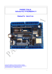
3.1.2 TestStand: The Industry-Standard Test Management Software
TestStand is a test management software environment developed by National Instruments (NI) for execution and development of automated test sequences. The software
is build to handle operations like sequencing of multiple test steps, calling test step
code modules, limit checking, user management, report generation or result collection.
TestStand highly utilises modules that are written in separate development languages for measurement code or individual test actions. With a set of adapters
allowing to call code modules written in a variety of languages it is even possible
to mix different programming languages in one test sequence. The current build-in
adapters link with Labview, LabWindows/CVI, C++/C, .NET, ActiveX/COM and
HTBasic.
Figure 3.5: TestStand System Architecture from TestStand User Manual[9, 1-4]
Figure 3.5 illustrates the TestStand system architecture. Major software compo-
18
3 Test Language Transformation
nents of TestStand include the TestStand engine, Sequence editor, Operator interface,
and module adapters. The essential part of the TestStand system architecture is the
engine. The TestStand engine runs sequences that contain different steps. Steps can
call external code modules utilising the standard adapter interface. This interface is
also used by sequences for calling subsequences.
The TestStand Sequence Editor represents the development environment. It
gives access to all TestStand features. Sequences can be created, edited, executed
and debugged. The built-in debugging tool is capable of setting breakpoints, Stepping
into, out of and over steps, tracing through program executioins, monitoring variables
and expressions during execution and performing an analysis of the sequence file to
locate errors.
The TestStand Operator Interface provide the possibility to create a custom
Graphical User Interface (GUI) for executing, debugging or editing, developed in any
programming language that can host ActiveX control or control ActiveX Automation
servers.
The TestStand Engine is a set of DLLs that provide access to the ActiveX Automation Application Programming Interface (API) that can be used to create, execute,
edit and debug sequences. This API is used by the sequence editor and Operator
Interface and can be called by any programming environment that supports ActiveX
Automation Servers.
Module Adapters are used to invoke code modules that are called by sequences.
A code module contains various functions that perform actions or specific tests. The
following adapters are included:
• LabView: Calls Labview VIs
• LabWindows/CVI: Calls C functions in a DLL
• C/C++ DLL: Calls C/C++ functions and static C++ class methods in a DLL
• .NET: Calls .NET assemblies
• ActiveX/COM: Calls methods and accesses properties of ActiveX/COM objects
• HTBasic: Calls HTBasic subroutines
• Sequence: passes parameters when calling subsequences.
The Graphical User Interface of TestStand provides the developer with various
building blocks. In the following an overview of the different TestStand blocks and
features are given.
In TestStand the places that store data values are called variables and properties. Variables can be created in certain contexts. They can be global to a sequence
19
3 Test Language Transformation
file, local to a certain sequence or station global to the computer the program is running on. Properties are containers of values. They can contain just a single value,
an array of values or various subproperties. Steps in sequences can store values in
properties. The properties of steps are determined by the type of the step.
Any TestStand sequence contains multiple steps. They can perform a variety of
tasks through several types of mechanisms. A step is capable to execute an expression, call a subsequence or an external code module. The step properties are used to
store parameters to pass to the code module, or serve as a place for the code module
to store the results. These properties are called custom properties and are different
for each step type. TestStand steps also have a number of built-in properties. The
Precondition property for example allows the specification of conditions that must be
true to execute the step. The Pre-/Postexpression property allows the specification
of an expression to evaluate before/after the execution of the step. The number of
custom properties a step has is determined by the step type. Every step of the same
type has the same custom properties in addition to the built-in properties. The predefined TestStand step types are as follows:
• Action
• Numeric Limit Test
• String Value Test
• Pass/Fail Test
• Label
• Goto
• Statement
• Limit Loader
• Message Popup
• Call Executable
• Sequence Call
In addition the test environment at Lufthansa Technik AG extend this set of types
by a number of custom steps:
• VTSA Numeric Limit Test
• VTSA Hexadecimal Limit Test
20
3 Test Language Transformation
• ChapterCall
• VTSA Post Text to Report
Any TestStand sequence consists of local variables, parameters, steps and built-in
properties. Sequence parameters are variables that store values passed by a sequence
call step. It is possible to pass parameters by value or by reference to any step in
the sequence. Local variables store values that are relevant for the execution of the
sequence. They apply only to the sequence they are created in. It is possible to run
multiple instances of the same sequence for example by calling this sequence recursively. In this case each instance of the sequence has its own parameters and local
variables.
3.1.3 Automatic test environments
Automatic test environments (ATE) are used to perform tests on a Unit Under Test
(UUT) using automation for measurements and evaluation of test results. Tests can
be performed by a single computer controlled digital multimeter up to a complex
system utilising multiple test instruments as well as AC and DC sources.
A desktop computer runs the test software and controls the test instruments via
different connections like PCI/PCIe, Ethernet, PXI/PXIe, USB, GPIB and several
more. Fast switching of instruments are realized by relays. A Test Unit Adapter
(TUA) is then used to connect the sensors and sources necessary for the test with
the UUT. This makes it possible to test multiple different UUTs using the same test
system but different test software and adapters.
Automatic test environments are widely used by electronics manufacturers for testing of components after fabrication, or by avionics and automotive companies for
maintenance and repair. Especially units that require regular testing of all parameters, like components that are critically important for human live, offer and area of
application for automatic testing.
ATLAS and TestStand are both programming languages for development of test
software for automatic test environments. The difference is, that the ATLAS test
software includes a hardware description of the TUA components. This information
need to be extracted before transformation, because hardware descriptions can not
be mapped to the TestStand software.
3.2 Requirements on the Translator
Like in any other language the two key components of ATLAS and TestStand are
syntax and semantics. That means the structure of the language, how symbols are
21
3 Test Language Transformation
ordered and what symbols to expect and the actual meaning of each symbol or set
of symbols. In this section the requirements on the grammar according to the syntax
are discussed as well as the demands on preserving the semantics.
3.2.1 Parsing ATLAS Syntax
The first task to accomplish is: How to design the grammar for parsing the source
language ATLAS? Section 3.1.1 shows ATLAS has grown to a very wide test language
used in a great number of automatic testing environments. This means, that not every aspect of the test language is necessary for testing avionic devices. So parts of the
syntax might never be used. Because there are only two major companies building
aircraft’s, the number of companies developing test programs for avionic equipment
is also fairly manageable. So there are not a lot developers writing new ATLAS code.
It is quite possible that developers rather reuse already existing code than write new
test programs from scratch.
This leads to the assumption that most parts of the test software does not differ
very much in terms of the structures that are used. Given that developing a grammar
that successfully parses every aspect of the ATLAS language is a very time consuming
task, building a grammar that does not picture the whole ATLAS syntax, but the
most common parts used in avionic test programs, suggests itself.
The problem with this approach is, that an incomplete grammar will lead to syntax errors while parsing. Therefore the robust parsing technique described in section
2.2.2 is needed. The implementation of such a technique is supported by two factors:
1. ATLAS programs exclusively consists of code lines that follow the standard
statement structure given in section 3.1.1 on page 13.
2. TXL grammars allow ambiguity. The parsing algorithm takes the first matching
alternative in the list as a success. This means providing a statement that
matches every input that has the standard ATLAS structure at the end of the
list, will catch all ATLAS statements that aren’t defined.
To implement robust parsing to TXL the non-terminal [A_unknown_statement]
is introduced. Listing 3.1 shows the unknown statement definition. The general
structure represents the standard ATLAS statement structure. A Statement number
followed by a ATLAS verb followed by a comma is accepted by the parser. The nonterminal A_remainder than accepts every input except the statement terminator
($).
Listing 3.1: Unknown Statement Definition
1 define A_unknown_statement
22
3 Test Language Transformation
2
3
% GENERAL ATLAS STATEMENT STRUCTURE
[ A_fstatno ] [ A_verb ] [ A _ f i e l d _ s e p a r a t o r ] [ repeat
A_remainder ] ’ $
4 end define
5
6 define A_remainder
7
%Bounded by t e r m i n a l symbol $
8
[ not ’ $ ] [ token_or_key ]
9 end define
10
11 define token_or_key
12
%TXL idiom f o r " any i n p u t "
13
[ token ] | [ key ]
14 end define
Every unknown statement can than be transformed to a special TestStand step,
that displays the unknown code line in the TestStand program. A developer might
transform these steps later by hand or the transformation system can be extended to
transform that statement properly.
3.2.2 Preserving Semantics in Avionic Environments
Preserving the semantics of the test software is an important part of the transformation system. The problem in this work is, that the semantics of nether ATLAS
nor TestStand are formally described. But proving semantically correctness is nearly
impossible with no formal descriptions of the source and target language. Developing
these formal descriptions is also not an option. Besides the immense amount of time
this would cost, the semantics described in the ARINC specification[5] are not precise
enough to deviate formal structures.
We will therefore take a practical approach: If the source program A and the transformed source program T get the same input, they have to produce the same output.
First, we will define, the input and output of A and T.
In automatic test environments, the possible input consists of all signals that come
from measurement equipment and the tested UUT, and also possible user input. With
the huge amount of data in different combinations it seems impossible to control the
semantics of the transformation process for all possible inputs. As stated in Section
3.2.1, there is a no need to transform the whole source language, but to focus on the
important aspects. To specify: only the semantics of those parts (that ought to be
transformed) must prevail. This way, the problem can be separated in different parts
and individual solutions for specific transformations should be considered. But what
are the really important parts of the program?
23
3 Test Language Transformation
The output of a test program is a report which summarizes the test results.This
report helps a technician to decide if a tested UUT is operational or not. If one
includes the user, the output can be defined as the reaction of the technician on the
report.Therefore it is important, that the technician can come to the same conclusion, not that both reports look exactly the same. Some informations are particularly
important for the equivalence of the output in the report. So how does a report like
this look like?
The key components of a test report are the informations that are available for
every single step.
• The distinct Test Step Number (TSN) for the precise identification of the test
steps.
• A short description of the test steps or the key components of the test steps,
like relevant pins.
• The measurement or the value for the comparison.
• The limits, in which the measurement was compared to create the test result.
• A conclusive result of the test: GO or NOGO.
It is very important that these informations are being ensured during the transformation pocess and can be found in the TestStand program. An important part of
the program is therefore the report generation. In ATLAS, the relevant statements
are the data processing statements CALCULATE and COMPARE as well as INPUT
and OUTPUT. Another significant part of a developing language is the program flow.
Executing the statements in the same order is essential for the program semantics. In
ATLAS, these statements are If-then-else-structures, procedures and functions. Anothert important aspect in automatic test languages is the hardware triggering, the
requirements to the hardware components as well as the commands to control them.
The rules of transformation of these components will be illustrated in chapter 4.
24
4 The Translator
4 The Translator
The transformation system is capable of parsing any ARINC 626-3 Spec ATLAS
source code and converting it into TestStand sequences. Thanks to the robust grammar, not implemented ATLAS statements can be transferred to the TestStand sequences without causing syntax errors. Figure 4.1 illustrates the schematic structure
of the transformation system.
Figure 4.1: Transformation Concept
Initially a small program merges all ATLAS source files into one input file. This
step mainly includes integrated modules and removes comments. To ease the parsing
process, dimensions are moved away from numerical values (5V → 5 V) and decimal
numbers less than 1 are corrected (.1 → 0.1).
The generated input file is then parsed with TXL into a tree structure. Listing 4.1
shows the basic grammar structure. The non-terminal define program marks the start
symbol. A_preamble_statement and A_procedural_statement are the non-terminals
that include a choice list of all essential statement definitions. At the end of each list
the unknown statements are intercepted.
25
4 The Translator
Listing 4.1: Basic ATLAS grammar structure
define program
[ A_begin_atlas_statement ] [ repeat preamble_statement ]
[ A_commence_statement ] [ repeat p r o c e d u r a l _ s t a t e m e n t ]
[ repeat b l o c k _ s t r u c t u r e ] [ A_terminate_atlas_statement ]
end define
define A_preamble_statement
[ A_extend_statement ]
|
[ A_require_statement ]
|
[ A_declare_statement ]
|
[ A_establish_statement ]
|
[ A_define_statement ]
|
[ A_identify_statement ]
|
[ A_unknown_preamble_statement ]
end define
define A_procedural_statement
[ A_declare_statement ]
|
[ A_calculate_statement ]
|
[ A_compare_statement ]
|
[ A_output_statement ]
|
[ A_input_statement ]
|
[ A_flow_control_statement ]
|
[ A_remove_statement ]
|
[ A_signal_statement ]
|
[ A_do_exchange_statement ]
|
[ A_subchapter_begin ]
|
[ A_subchapter_end ]
|
[ A_unknown_procedural_statement ]
end define
After converting the input file to a parse tree structure, the TXL transformation rules
are applied. A precise definition of the transformation rules are provided in section
4.1. At the end, the generated TestStand macros are imported by the TestStand Assembler program and a runnable sequence file is created. The TestStand Assembler
and the macro commands are presented in section 4.2.
4.1 Transformations
In this section, the different ATLAS structures are explained in detail. The semantics
are presented and the equivalent representations in TestStand as well as the rules that
26
4 The Translator
transform the statements are explained. Because there are no formal descriptions of
the semantics, every transformation rule is best practice.
4.1.1 Preamble
Preamble statements describe the structure, environment and variables of the test
program.
Hardware Resources
These statements primary describe the requirements on the different hardware resources. In ATLAS these statements are also called virtual resources. They define
the type of hardware that need to be used as well as ranges and limits that are required.
Listing 4.2: ATLAS Require Source Example Statement
REQUIRE, ’DC−SUPPLY ’ , SOURCE, DC SIGNAL ,
CONTROL,
VOLTAGE RANGE 0 V TO 120 V BY 0 . 0 1V ERRLMT +−0.01 V,
CAPABILITY,
CURRENT MAX 1 . 2 A,
LIMIT ,
CURRENT−LMT MAX 1 A,
CNX HI LO $
Listing 4.2 shows a typical ATLAS require statement. The resource requirements
are always divided into control, capability, limit and cnx (connection) parameters.
The virtual resource DC-SUPPLY represents a DC voltage Source with a range from
0V to 120V adjustable in 0.01 V steps with an accuracy of +-0.01V and the capability
of a current of 1.2 A maximum. It also needs the ability of limiting the current to
maximum 1 A. The proper example of use is shown in Listing 4.3. The virtual resource
DC-SUPPLY is used with the instructions illustrated in Table 4.1.
Line
1
2
3
4
5
Instruction
Control action
Voltage
Current max
Connection HI
Connection LO
Value
APPLY
18.7 V
0.5 A
J1A-30
J1A-03
Table 4.1: Example APPLY Statement Instructions
27
4 The Translator
Listing 4.3: ATLAS Apply Example Statement
1 APPLY, DC SIGNAL USING ’DC−SUPPLY ’ ,
2
VOLTAGE 1 8 . 7 V ERRLMT +−0.01 V,
3
CURRENT MAX 0 . 5 A,
4
CNX HI J1A−30
5
LO J1A−03 $
The Transformation of hardware resources is reduced to just creating the Teststand
sequence stub. Filling these stubs with actual hardware control instructions is outside the scope of this work, since an engineer needs to select the hardware that is
available at the test facility. However, the instructions need to be transferred to the
hardware sequence when calling it later on. Therefore the sequence needs to feature
the parameters established in the requirement definition.
Listing 4.4: Transform Require Rule
1 rule t r a n s f o r m R e q u i r e
2
replace [ preamble_statement ]
3
R e q u i r e [ A_require_statement ]
4
deconstruct ∗ [ l i s t c h a r l i t ] R e q u i r e
5
Names [ l i s t c h a r l i t ]
6
deconstruct ∗ [ A_require_type ] R e q u i r e
7
Type [ A_require_type ]
8
construct T_Require [ repeat T e s t s t a n d S t a t e m e n t ]
9
%empty
10
where not
11
Type [ i s E v e n t M o n i t o r ]
12
by
13
T_Require [ c o n v e r t R e q u i r e R e q u i r e each Names ]
14 end rule
Listing 4.4 illustrates the main transformation rule for hardware requirements. The
resource EventMonitor is not needed to hold events and doesn’t need to be translated to a sequence stub. In Teststand events are stored in a global container variable.
Therefore the constrained not isEventMonitor is included in lines 10 and 11. Because
it is possible to define multiple resources with different names, but the same ranges
and limits the function convertRequire is called in line 13 for each virtual resource
name.
Listing 4.5: Convert Require Function
1 function c o n v e r t R e q u i r e R e q u i r e [ A_require_statement ]
Name [ c h a r l i t ]
2
replace [ repeat T e s t s t a n d S t a t e m e n t ]
28
4 The Translator
3
T_Require [ repeat T e s t s t a n d S t a t e m e n t ]
4
5
deconstruct R e q u i r e
6
F [ A_fstatno ] ’REQUIRE ’ , _[ l i s t c h a r l i t ] ’ , Type
7
[ A_require_type ] ’ , Noun [ A_noun ] C o n t r o l
8
[ A_require_control ] Capability [ A_require_capability ]
9
_[ A _ r e q u i r e _ l i m i t ] Cnx [ A_require_cnx ] ’ $
10
11
construct ConCap [ l i s t A_require_body ]
12
_[ getBodyControl C o n t r o l ] [ g e t B o d y C a p a b i l i t y C a p a b i l i t y ]
13
14
construct T _ v a r i a b l e s [ repeat T _ v a r i a b l e s ]
15
’ v a r i a b l e ’ € ’ ’ Action ’ ’ € ’ S t r i n g ’ € ’ I n p u t p a r a m e t e r ’ € ;
16
’ v a r i a b l e ’ € ’ ’ Return ’ ’ € ’ Number ’ € ’ Outputparameter ’ € ;
17
18
construct newRequire [ T e s t s t a n d S t a t e m e n t ]
19
’ s e q u e n c e ’ € ’ B u i l d S e q u e n c e ’ € Name ’ € ’ Hardware ;
20
’ s e q u e n c e ’ € ’ S e t S e q u e n c e ’ € Name ;
21
T _ v a r i a b l e s [ g e t R e q u i r e V a r i a b l e s each ConCap ]
22
[ getRequireCnx Cnx ] [ g e t E x t r a V a r i a b l e s Noun ]
23
’ sequence ’€ ’ ResetSequence ;
24
25
by
26
T_Require [ . newRequire ]
27
28 end function
The function convertRequire shown in Listing 4.5 constructs the macros needed
to build a new hardware sequence. To get the remaining instruction parameters that
are needed for later sequence calls, the require statement is deconstructed in lines
5-9. The control, capability and connection information are stored in the variables
Control Capability and Cnx. The functions getRequireVariables and getRequireCnx in
lines 21 and 22 are extracting the instruction parameter names from the variables and
construct the corresponding variable macros. The function getExtraVariables covers
the fact, that a time interval also needs the parameters from, to and max-time. The
macro commands SetSequence and ResetSequence in lines 20 and 23 make sure the
assembler puts the variables into the right sequence.
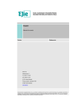
Procedures and Functions
These structures contain ATLAS code, that is often used in the program flow. Input and output parameters provide the possibility to transfer values from and to the
procedure or function during calls. Procedures can be called by a perform statement
29
4 The Translator
and functions are used in an expressions similar to variables. The equivalent representation in Teststand is a sequence with the cutback, that sequences can’t be called
in a expression. However the solution to this restriction was outside of the scope of
this work, therefore the case study doesn’t contain functions. This section focusses
on the definition of procedures.
Figure 4.2: ATLAS Procedures
Figure 4.2 illustrates the schematic representation of ATLAS procedures. Inputparameters, Outputparamets and local variable definitions are optional. The DEFINE
and END statements act as delimiter at the start and end of the procedure, where
the Procedurename acts as a unique identifier. To compare the names the best way
is to transform the hole structure altogether.
1
2
3
4
5
6
7
8
9
10
11
12
13
14
15
16
17
Listing 4.6: Procedure Transformation Rule
rule t r a n s f o r m P r o c e d u r e
replace [ preamble_statement ]
F [ A_fstatno ] ’DEFINE , Name [ c h a r l i t ] , ’PROCEDURE
Parameter [ A _ p a r a m e t e r _ d e f i n i t i o n ] ’ $
SubScope [ repeat p r o c e d u r a l _ s t a t e m e n t ]
F1 [ A_fstatno ] ’END , Name1 [ c h a r l i t ] ’ $
where %Test i f s t a r t and end p r o c e d u r e names a r e e q u a l
Name [= Name1 ]
construct I n p u t p a r a m e t e r [ l i s t A_input_parameter ]
_ [ g e t I n p u t Parameter ]
construct Outputparameter [ l i s t A_output_parameter ]
_ [ getOutput Parameter ]
construct Input [ repeat T _ v a r i a b l e s ]
_ [ c o n v e r t P a r a m e t e r I n p u t each I n p u t p a r a m e t e r ]
construct Output [ repeat T _ v a r i a b l e s ]
_ [ convertParameterOutput each Outputparameter ]
by
’ s e q u e n c e ’ € ’ B u i l d S e q u e n c e ’ € Name ’ € ’ Proced ure ’ ;
30
4 The Translator
18
19
20
21
22
23 end
’ s e q u e n c e ’ € ’ S e t S e q u e n c e ’ € Name ’ ;
’ v a r i a b l e ’€ ’ ’ Variables ’ ’€ ’ Container ’€ ’ Locals ’€ ;
Input [ . Output ]
SubScope [ p r o c e d u r a l T r a n s f o r m a t i o n s ]
’ sequence ’€ ’ ResetSequence ’ ;
rule
The procedure transformation rule is shown in Listing 4.6. In line 7 the name condition is checked. The input- and outputparameters are converted in lines 13 and 15
and the resulting macro commands are concatenated with the TXL built-in function
"." in line 20. Statements and local variables of the procedure are stored in the SubScope variable. To transform the content, the procedureTransformations function is
called. The macro commands SetSequence and ResetSequence in lines 18 and 22 make
sure the variables and statements are put into the right sequence by the assembler.
Variable Types
Table 4.2 illustrates the different variable types available in ATLAS, what they are
transformed to and if they are implemented yet. Due to the limitations on TestStand
variable types, it is not possible to find equivalent variable types. However this is
not required to achieve a semantically equivalent result in an avionic test environment. Below the different ATLAS variable types and their TestStand counterparts
are discussed:
1. Enumeration
Enumerations are not implemented to Teststand. However it is possible to
utilize the Container structure that is comparable with a struct in C to accomplish a similar result. Pre-declared ATLAS enumeration types are Boolean,
Char-Class and Dig-Class. While Boolean has an equivalent counterpart in
TestStand, Char-Class and Dig-Class can be translated like any other enumeration.
2. Connection
Connections are used to identify hardware pins of the UUT in ATLAS. Because
hardware control is not in the scope of this work, it is sufficient to save the connection name in a string variable and hand them over to the hardware sequence,
which will handle the connections of instruments to the corresponding pin.
3. Decimal, Integer and Bit
Numeric variables are entirely translated to the TestStand Number type. The
default representation is a double precision 64-bit floating point variable and it
is possible to change the representation to a signed or unsigned 64-bit Integer
but it is not possible to change the precision any further. So the intentional
usage of a wrap around need to be considered but is not expected in avionic
testing.
31
4 The Translator
4. Char
A char represents a single character. TestStand doesn’t contain variable types,
that represent a single character, this is why a char is transformed to a string.
5. Array
An array is a data structure consisting of a collection of elements, that can be
identified by an index. This structure also exists in TestStand. Therefore it
can be translated directly. However, arrays are not very common in ATLAS
test programs and are not used by the case study. This is why arrays are not
implemented yet.
6. String of Type A string of type basically is the same as a TestStand string
with the exception, that the characters of the string are more precisely defined.
Because the ATLAS source code is considered to be faultless, it is not expected
that wrong characters are stored in this variable. This is why the TestStand
string type is considered to be equivalent.
7. Record and File These data types have no equivalent counterparts in TestStand,
but are seldom used. It is recommended to find a work around with a NI
LabView VI, or a C++ dll.
ATLAS type
Enumeration
Connection
Decimal
Integer
Char
Bit
Boolean
Char-Class
Dig-Class
Array
String () of Type
Record
File
Teststand type
Number-Container
String
Number
Number
String
Number
Boolean
Number-Container
Number-Container
Array
String
−
−
Implemented
−
X
X
X
X
X
X
−
−
−
X
−
−
Table 4.2: ATLAS and Teststand Variable Type Comparison
4.1.2 Flow control
Flow control statements provide the capability to control the order of statement
execution. The ARINC specification 626-3 combines them in the chapter Procedural statements control[5]. Because short circuit semantics are not mentioned in the
32
4 The Translator
specification it is assumed that they are not implemented, whereas TestStand does
implement short circuit evaluation. This difference could be compensated by manipulating the underlying C++ code of the relevant flow control steps but this is outside
the scope of this work. Given that the example source code doesn’t use conditions
that would be violated by short circuit evaluation, this difference is irrelevant for the
evaluation. Nevertheless it needs to be considered for other source code transformations in the future.
If then else/else if Structures
These structures control the execution of statements provided that certain condition
expressions evaluate to true or false. The functional flow of these structures is shown
in the ARINC specification 626-3 [5] on page 151. The semantics are very similar to
each other, so the transformation to Teststand is very straight forward. Listing 4.7
illustrates the different transformation rules needed. The statements IF, ELSE IF,
ELSE, LEAVE and END have a equivalent representation in teststand.
Listing 4.7: If then else/else if Tranformation Rules
rule t r a n s f o r m _ I f
replace [ p r o c e d u r a l _ s t a t e m e n t ]
F [ A_fstatno ] ’ IF , Expr [ repeat A_expression ] , ’THEN ’ $
by
’ s t e p ’ € ’ NI_Flow_If ’ € F ’ I f ’ €
Expr [ t r a n s f o r m E x p r e s s i o n s ] ’ € F ’ IF , Expr , ’THEN
’$ ;
6 end rule
7
8 rule t r a n s f o r m _ E l s e _ I f
9
replace [ p r o c e d u r a l _ s t a t e m e n t ]
10
F [ A_fstatno ] ’ELSE ’ IF , Expr [ repeat A_expression ] ,
’THEN ’ $
11
by
12
’ s t e p ’ € ’ NI_Flow_ElseIf ’ € F ’ E l s e I f ’ €
Expr [ t r a n s f o r m E x p r e s s i o n s ] ’ € F ’ELSE ’ IF , Expr ,
’THEN ’ $ ;
13 end rule
14
15 rule t r a n s f o r m _ E l s e
16
replace [ p r o c e d u r a l _ s t a t e m e n t ]
17
F [ A_fstatno ] ’ELSE ’ $
18
by
19
’ s t e p ’ € ’ NI_Flow_Else ’ € F ’ E l s e ’ € F ’ELSE ’ $ ;
1
2
3
4
5
33
4 The Translator
20 end rule
21
22 rule transform_Leave
23
replace [ p r o c e d u r a l _ s t a t e m e n t ]
24
Leave [ A_leave_statement ]
25
deconstruct ∗ [ A_fstatno ] Leave
26
F [ A_fstatno ]
27
by
28
’ s t e p ’ € ’ Leave ’ € F ’ Leave ’ € Leave ;
29 end rule
30
31 rule transform_End
32
replace [ p r o c e d u r a l _ s t a t e m e n t ]
33
End [ A_end_statement ]
34
deconstruct ∗ [ A_fstatno ] End
35
F [ A_fstatno ]
36
by
37
’ s t e p ’ € ’ End ’ € F ’ End ’ €€ End ;
38 end rule
While
This structure provides the possibility to repetitively execute statements as long as
a certain condition evaluates to true. Listing 4.8 illustrates the while transformation
rule. The NI_Flow_While step is the equivalent representation of the WHILE statement.
Listing 4.8: While Tranformation Rules
rule transform_While
replace [ p r o c e d u r a l _ s t a t e m e n t ]
F [ A_fstatno ] ’WHILE , Expr [ repeat A_expression ] ,
’THEN ’ $
4
by
5
’ s t e p ’ € ’ NI_Flow_While ’ € F ’ While ’ €
Expr [ t r a n s f o r m E x p r e s s i o n s ] ’ € F ’WHILE , Expr ,
’THEN ’ $ ;
6 end rule
1
2
3
For
This structure provides the possibility to repetitively execute statements for a defined
amount of iterations. Because the Teststand NI_Flow_For step is equivalent to the
34
4 The Translator
ATLAS FOR statement, the counter variable, initial value, increment value and maximum value are just handed over to the macro assembler. Listing 4.9 illustrates the
for transformation rule. If the increment value is not defined, it is set to 1 by default
in ATLAS. Therefore the convert_Default_For rule manipulates the ATLAS code to
match the replacement condition of the transform_For rule.
Listing 4.9: For Tranformation Rules
rule transform_For
replace [ p r o c e d u r a l _ s t a t e m e n t ]
F [ A_fstatno ] ’FOR , Counter [ c h a r l i t ] ’= I n i t i a l
[ number ] ’THRU End [ number ] ’BY Increment [ number ] ,
’THEN ’ $
4
by
5
’ s t e p ’ € ’ NI_Flow_For ’ € F ’ For ’ € Counter ’ € I n i t i a l
’ € End ’ € Increment ’ € F ’FOR , Counter ’= I n i t i a l
’THRU End ’BY Increment , ’THEN ’ $ ;
6 end rule
7
8 rule convert_Default_For
9
replace [ p r o c e d u r a l _ s t a t e m e n t ]
10
F [ A_fstatno ] ’FOR , Counter [ c h a r l i t ] ’= I n i t i a l
[ number ] ’THRU End [ number ] , ’THEN ’ $
11
by
12
F ’FOR , Counter ’= I n i t i a l ’THRU End ’BY 1 , ’THEN ’ $
13 end rule
1
2
3
Perform
This statement directs the program flow to a procedure. The procedure is identified
by a unique name. It is possible to assign input values or variables and return variables. After executing the procedure statements, the program flow continues from
this statement. Because procedures are transformed to sequences, the equivalent Teststand step is a SequenceCall. Listing 4.10 illustrates the perform transformation rule.
Listing 4.10: Perform tranformation Rules
1
2
3
4
5
6
rule transform_Perform
replace [ p r o c e d u r a l _ s t a t e m e n t ]
F [ A_fstatno ] ’PERFORM , Name [ c h a r l i t ] Input
[ A_perform_parameters ] ’ $
construct T_Input [ l i s t A_expression ]
_ [ g e t P e r f o r m I n p u t Input ]
construct T_Output [ l i s t A_expression ]
35
4 The Translator
7
8
9
_ [ getPerformOutput Input ]
by
’ s t e p ’ € ’ S e q u e n c e C a l l ’ € F ’ Perform ’ € Name ’ €
T_Input [ , T_Output ] [ t r a n s f o r m E x p r e s s i o n s ] ’ € F
’PERFORM , Name Input ’ $ ;
10 end rule
Finish
This statement ends the program execution immediately. Because there is no direct
equivalent Teststand step, a number of steps are required to induce an equivalent behaviour. This is explained in section 4.2.2. As listing 4.11 shows the transformation
rule for the macro command is fairly simple.
Listing 4.11: Finish Transformation Rules
1 rule t r a n s f o r m _ F i n i s h
2
replace [ p r o c e d u r a l _ s t a t e m e n t ]
3
F [ A_fstatno ] ’ FINISH ’ $
4
by
5
’ s t e p ’ € ’ F i n i s h ’ € F ’ F i n i s h ’ € F ’ FINISH ’ $ ;
6 end rule
Wait
This statement suspends the program execution until a condition is satisfied. It is
possible to wait for a certain time, a specific timer to reach a specified time quantity,
a particular event to occur or a human manual intervention. In the scope of this
work, just the first condition is transformed, therefore the other options aren’t used
very often. Listing 4.12 illustrates the transformation rule. The equivalent Teststand
step to a wait for time statement is a wait step. Because the ATLAS statement
considers the time dimension and the Teststand step always uses milliseconds, the
convertTimeDim function in line 7 converts the time dimensions accordingly.
Listing 4.12: Wait Transformation Rules
1
2
3
4
5
6
rule transform_Wait
replace [ p r o c e d u r a l _ s t a t e m e n t ]
F [ A_fstatno ] ’WAIT ’FOR , ’TIME Time [ A_time_quantity ]
’$
construct T_time [ number ]
0
by
36
4 The Translator
7
’ s t e p ’ € ’ NI_Wait ’ € F ’ Wait ’ € T_time [ converTimeDim
Time ] ’ € F ’WAIT ’FOR , ’TIME Time ’ $ ;
8 end rule
4.1.3 Data Processing
Data processing statements provide the capability to save test values for further use
in the test procedure, perform calculations on these value and compare test values
with specified limits.
Calculate
The calculate statement evaluates an expression on the right side of an equals sign
and assigns the value to the variable on the left side of the equals sign. It is possible
to make more evaluations by separating each assignment by a comma.
This functionality can be provided by a statement step in TestStand. Every
evaluation-assignment pair can be written in the post-expression property and is
conveniently also separated by a comma.
Listing 4.13: Transform Calculate Rule
rule t r a n s f o r m C a l c u l a t e
replace [ p r o c e d u r a l _ s t a t e m e n t ]
F [ A_fstatno ] ’CALCUALTE ’ , Expr [ repeat A_expression ] ’ $
by
’ s t e p ’ € ’ Statement ’ € F ’ C a l c u a l t e ’ € Expr
[ t r a n s f o r m E x p r e s s i o n s ] ’ € F ’CALCUALTE ’ , Expr ’ $ ;
end rule
Listing 4.13 shows the transformation rule for calculate statements. The replacement rule is straight forward so only one subrule to transform the expressions is
needed. This means the main challenge is to translate these expressions properly.
For further information about expression transformation see section 4.1.5 on page
40. In the scope of this work, the expression transformation is just focused on the
expressions we encountered in the example code. So in future work the complete
transformation of the expressions is recommended.
Compare
This statement compares a variable with the limits defined in an evaluation field. This
comparison and the results are then printed to the report. The equivalent Teststand
step is the VTSA Numeric Limit Test. Important information are the variable name,
37
4 The Translator
the dimension of the value it represents, the evaluation format and the limits. For
the report, we also need the test step number(TSN) and a test description. Listing
4.14 shows the transformation rule in TXL.
Listing 4.14: Transform Compare Rule
1
2
3
4
5
6
7
8
9
10
rule transformCompare
replace [ p r o c e d u r a l _ s t a t e m e n t ]
F [ A_fstatno ] ’COMPARE ’ , Var [ c h a r l i t ] ’ , Comp [ repeat
A_comparison_value ] ’ $
construct Dim [ A_dim ]
’NODIM
construct Body [ repeat T_compare_body ]
_ [ getCompareValues each Comp ]
by
’ s t e p ’ € ’ VTSA_NumericTest ’ € F ’ Compare ’ € Var ’ € ’ €
Dim [ g e t A t l a s D i m e n s i o n Comp ] Body ’ € F ’COMPARE ’ , Var
’ , Comp ’ $ ;
end rule
The function getAtlasDimension in line 9 does aestetic transformations to the appearance of the dimension description in the report. Table 4.3 shows the conversions
we needed for the case study.
The function getCompareValues in line 7 transforms the evaluation field (Comp
[repeat A_comparison_value]) that is expressed in line 3.
ATLAS
dimension
USEC
MSEC
SEC
Teststand
dimension
us
ms
s
Table 4.3: Dimension Conversions
To get the possible evaluation formats for the evaluation field, we need to take a
look at table 4.4. Each row lists a field format and the result different variable values
will establish.
4.1.4 Hardware Control Statements
Signal statements primarily control the hardware components. The ARINC specification 626-3 combines them in the chapter Procedural statements signal [5, 189].
38
4 The Translator
Evaluation
Field Format
UL y LL z
GT x
LT x
EQ x
NE x
GE x
LE x
Value of
Variable v
v>y
y≥v≥z
z>v
v>x
v≤x
v<x
v≥x
v=x
v<>x
v<>x
v=x
v≥x
v<x
v≤x
v>x
Conditions
Established
Hi & NOGO
GO
LO & NOGO
GO
LO & NOGO
GO
LO & NOGO
GO
LO & NOGO
GO
LO & NOGO
GO
LO & NOGO
GO
LO & NOGO
Teststand
equivalent
GELE y z
GT x
LT x
EQ x
NE x
GE x
LE x
Table 4.4: Evaluation Field Relationships from Table 14-1 [5, 274]
Therefore hardware control is not in the scope of this work, the control actions, as
well as the values and limits are passed to the according hardware sequence. So most
of these statements can be transformed with one rule.
Statements that can be transformed by the rule transformSignal in listing 4.15:
• APPLY
• REMOVE
• CHANGE
• SETUP
• CONNECT
• DISCONNECT
• ARM
• FETCH
• RESET
• VERIFY
39
4 The Translator
• READ
Listing 4.15: Signal Statement Transformation Rule
1
2
3
4
5
6
7
8
9
10
11
12
13
14
15
16
17
rule t r a n s f o r m S i g n a l
replace [ p r o c e d u r a l _ s t a t e m e n t ]
F [ A_fstatno ] Verb [ A_signal_verb ] ’ , Mes [ A_measured_char ]
Noun [ A_noun_field ] ’ , Body [ l i s t A_require_body ] _[ opt
A _ f i e l d _ s e p a r a t o r ] Cnx [ A_conn_signal ] ’ $
deconstruct ∗ [ c h a r l i t ] Noun
Requirename [ c h a r l i t ]
deconstruct Cnx
’CNX Pins [ repeat A_Pins ]
construct Verbid [ i d ]
_[ u n p a r s e Verb ]
construct Return [ A_body_remainder ]
0
construct Parameters [ repeat T_signal_body ]
’ € ’ Action ’ , Verbid
’ € ’ Return ’ , Return [ getReturnValue Mes ]
by
’ s t e p ’ € ’ S i g n a l C a l l ’ € F Verbid ’ € Requirename
Parameters [ g e t S i g n a l P a r a m e t e r B o d y each Body ]
[ g e t S i g n a l P a r a m e t e r C n x each Pins ] ’ € F Verb ’ , Mes
Noun ’ , Body ’ , Cnx ’ $ ;
end rule
4.1.5 Expressions
An expression consists of one or more expression items, that are links via a mathematical, boolean and/or logic operator. Table 4.5 shows the different possible operators
and their equivalent counterpart in TestStand.
Most of these operators are expressed in the same way in ATLAS and TestStand.
That means that a lot of the parts of an expression don’t need to be transformed at
all. An expression item may be one of these for items:
• predefined or in preamble defined function
• another expression in parenthesis
• A variable
• a constant
40
4 The Translator
ATLAS
Operation
EQ
NE
GT
LT
GE
LE
XOR
OR
AND
NOT
+
**
*
/
DIV
MOD
&
Description
Equality
Inequality
Greater than
Less than
GT or EQ
LT or EQ
Exclusive OR
Logical OR
Logical AND
Logical NOT
Addition
Substraction
Exponentiate
Multiply
Division
Division
Modulo
Concatenation
Teststand
equivalent
== or EQ
!= or NE
> or GT
< or LT
>= or GE
<= or LE
XOR
OR
AND
NOT
+
Exp()
*
/
/
MOD
&
Table 4.5: Mathematical and Logical Conjunctions in ATLAS and TestStand
Variables in TestStand are stored in different places. That is why the TestStand assembler needs to evaluate the path of every variable. Therefore a transformation in
TXL is is not necessary.
A list of all predefined functions is included to the ARINC Spec 626-3 [5, 134].
The functions that are transformed so far are COPY(A,B,C) to Mid(A,B+1,C) and
BITS( ASCII7 , A) to Asc(A). It is not possible to call sequences from expressions in
TestStand, therefore custom functions can’t be implemented to TestStand without a
big effort. At this place a work around in the future needs to be considered. In most
cases ATLAS custom functions implement functionalities, that are already existing
in TestStand pre defined functions. Because the case study doesn’t use custom functions, they have not been implemented.
4.2 Teststand Assembler
The TestStand assembler is developed in TestStand to provide the possibility to create
binary sequence files. This is possible, because die TestStand API provides the possi-
41
4 The Translator
bility to manipulate existing persisted TestStand objects and to create new object on
runtime. Nevertheless TestStand primarily is a management software for automated
test environments. Most of the transformations should be done by the TXL rules.
Therefore the TestStnad assembler is designed to execute basic marco commands to
create TestStand steps, sequences and variables. These commands are explained in
the following.
4.2.1 Concept
The macro command list is being executed from top to bottom. Every macro command has a similar structure:
Category € Type € Name € Additional information € ATLAS code ;
There are four different Categories:
1. Steps : to create new TestStand steps
2. Sequences: To create new sequences and control in which sequence steps are
stored
3. Variables: To Declare and initialize new variables
4. edit: To Manipulates existing structures
In the following each macro command of the different categories is introduced.
Terminal symbols are bold variable symbols italic.
Step
This category includes every macro that is related to the creation of new TestStand
steps.
step € Label € Label name € ATLAS code ;
A Label has no effect on the actual program. It is used to display comments for
instance.
step € Unknown € Unknown Codeleine € § ATLAS code § ;
An unknown statement is a special form of a lable. It always has the name Unknown
Codeline and different display icon. To make a TestStand sequence runnable, at first
all Unknown statements need to be translated by hand.
step € nop € § ATLAS code § ;
42
4 The Translator
Another special form of a label step. This step represents ATLAS statements that
are not necessary for the correct execution of the test program.
step € NI_Flow_If € Statement number If € Condition € ATLAS
code ;
step € NI_Flow_ElseIf € Statement number If € Condition € ATLAS code ;
step € NI_Flow_While € Statement number While € Condition €
ATLAS code ;
Creates an If/Elseif/While step. At the Condition variable the condition expression
is assigned.
step € NI_Flow_For € Statement number For € Loop variable € Start
number € Number of loops € Increment value € ATLAS code ;
Creates a For step. The Loop variable represents the variable where the Index of
the for loop is stored. The Start number variable indicates, with what number the
Loop variable is initiated. The Number of loops is the upper limit and the Increment
value variable indicates the incrementation number.
step € End € Statement number End € ATLAS code ;
Creates an End step which marks the end of an if/for/while structure.
step € Leave € Statement number Leave € ATLAS code ;
Creates a Break step, that allows to jump out of if/for/while structures.
step € Report € Statement number Message € Text output € ATLAS
code ;
Creates a VTSA_PostText step to print text into the report. The variable Text output
contains the actual text, but can also contain additional variables, that have to be
mapped by the Assembler.
step € MessagePopup € Statement number Message € Input type €
ATLAS code ;
Creates a Message Popup step, that displays a popup message on run time. The Input
type variable indicates if the input is a text or a button input.
step € NI_Wait € Statement number Wait € Number € ATLAS code
;
Creates a wait step. The Number indicates the waiting time in seconds.
step € Statement € Statement number Name € Expression € ATLAS
code ;
43
4 The Translator
Creates a Statement step. The Expression variable contains the expression that has
to be performed. The translation of the variables in the Expression is handled by the
assembler.
step € Finish € Statement number Finish € ATLAS code ;
Creates a specific statement step that terminates the test run.
step € VTSA_NumericTest € Statement number Compare € Compare Variable € Compare pins €€ Dimension € Compare limits ATLAS
code ;
Creates a VTSA_Numeric_Limit Test step, that compares values with one another
and writes the results into the report. Compare Variable contains the variable that
ought to be compared. The compare pins variable contains the information at what
pins data is measured, so that they can be displayed in the report. The Dimension
variable explains the dimension of the compared values (zB. Ω oder V). The Compare
limits variable contains the information about the kind of comparison and the values
for the comparison.
step € SequenceCall € Statement number Perform € Sequence name
€ Parameters € ATLAS code ;
Creates a Sequence Call Step that invokes another sequence. The Sequence name
variable states the Name of the invoked sequence. In the Parameters, a comma
separated list contains the transfer parameters.
step € SignalCall € Statement number
Parameters € ATLAS code ;
Action € Sequence name €
Creates a Sequence Call step that activates one of the Sequences which contain the
hardware triggering. Action represents the kind of call (APPLY etc). The Sequence
name variable indicates the Name of the Hardware-Sequence to be invoked. In the
Parameters, a comma separated list contains the transfer parameters.
step € EventCall € Statement number Action € Event name € ATLAS
code ;
Creates a Sequence Call step, that calls a sequence that is connected with an event. At
launch, a global variable is retrieved which contains all events and their parameters.
There is no need to transfer parameters at this point. The name of the event is
deposited in Event name.
step € ExchangeCall € Statement number Action € Exchange name €
Parameters € ATLAS code ;
Creates Sequence Call step that calls one of the sequences which are connected with
a bus protocol. At launch, a global variable is retrieved which contains some of the
parameters. The name of the exchange protocol is filed in Exchange name. Further
parameters are exchanged via Parameters.
44
4 The Translator
Sequence
This category contains all macros that are necessary to create a sequence and to
control in which sequences variables and steps shall be saved.
sequence € BuildSequence € Sequence name € Sequence type ;
Creates a new sequence with the name Sequence Name. The Sequence type variable
solely creates a sequence description for aesthetic purposes that has no effect on the
procedure.
sequence € BuildChapter € Chapter name ;
Creates a new chapter. A chapter is a specific sequence that is called from the start
sequence automatically (MainSequence). A chapter holds a complete testchapter.
Chapter are independent from one another and create entry points of the test program.
Before every test run one can decide which test chapter should be launched.
sequence € SetSequence € Sequence name ;
Sets the global variable FileGlobals.ActualSequence (which contains the reference of
the current sequence) to the sequence with the name Sequence Name. All subsequent
steps and variables are therefore automatically written into this sequence.
sequence € RestSequence ;
Sets the global variable FileGlobals.ActualSequence back to the MainSequence.
Variable
This category contains all makros for the creation of variables.
variable € Names € Type € Location € Initials ;
Declares and initializes variables. Names is a comma seperated list with variable
names and Initials is a comma seperated list with their initial values. Types states
the kind of variable and Location states the storage location. So far, these types are
implemented:
• number
• string
• container
Also, variables for custom types can be forwarded. storage locations can be:
• Locals
• Inputparameter
• Outputparameter
• FileGlobals
• Exchange
45
4 The Translator
Edit
With this category, one can manipulate existing structures or save typedefs.
edit € Begin € Program name ;
edit € Terminate € Program name ;
Mark the beginning and the end of the ATLAS program and therefore don’t have any
impact on the program. Only the Program name is analysed and compared.
edit € Variable € Name € Initial ;
Variable values can be changed further in the process.
edit € Type € Name € Type ;
Adds a custom type to the global variable fileGlobals.Types with the name Name and
the predefined type Type.
4.2.2 Construction Examples
This section illustrates the implementation of some of the macros with the help of
exemplary code from the TestStand Assembler. The specific commands are processed
top-down.
Finish
Because Teststand does not have a dedicated step to end a test run, a statement step
is induced to accomplish this.
This particular example shows the general use of the TestStand API. Listing 4.16
illustrates the API commands that are executed in the Create New Finish Statement
step depicted above. The effect of each code line is explained in the following:
1. Creates a new Statement step and forwards the object reference to the NewStep
variable.
2. Creates a command in the subproperty PostExpression, so that the step can set
his own status to Passed on run time.
3. Manipulates the subproperty PassAction and sets the value to Terminate.
4. Sets the step name.
46
4 The Translator
5. Forwards the corresponding ATLAS code as a comment.
6. The variable FileGlobals.ActualSequence holds a reference object to the sequence
to write to. The API command InsertStep inserts the step into the sequence.
1
2
3
4
5
6
Listing 4.16: Using TestStand API to build a new Step
L o c a l s . NewStep = RunState . Engine . NewStep ( " " , " Statement " ) ,
L o c a l s . NewStep . AsStep . P o s t E x p r e s s i o n =
" RunState . Step . R e s u l t . S t a t u s =\" Passed \ " " ,
L o c a l s . NewStep . AsStep . P a s s A c t i o n = " Terminate " ,
L o c a l s . NewStep . AsStep . Name = Trim ( L o c a l s . S t e p a r r a y [ 2 ] , " ’ " ) ,
L o c a l s . NewStep . AsPropertyObject . Comment =
Str ( Locals . Steparray [ 3 ] ) ,
F i l e G l o b a l s . A c t u a l S e q u e n c e . AsSequence . I n s e r t S t e p (
L o c a l s . NewStep , F i l e G l o b a l s . A c t u a l S e q u e n c e .
AsSequence . GetNumSteps ( StepGroup_Main ) , StepGroup_Main ) ,
PassAction is implemented in every step and controls what ought to happen after the
step, when the status of the step is Passed. Usually, the next step in line is activated,
but in this case, the program is shut down. Because the statement can manipulate
its own status on runtime with the help of the TestStand API, the termination of the
test program is ensured.This steps looks like shown below. The row 999998 FINISH
$ shows the comment field and the associated ATLAS code.
For
Another example is the creation of a For Step. As mentioned in Section 4.2.1, this
step contains a Loop variable. Because it is unclear (at that moment) where this
variable is stored, it has to be searched for inside the program. Because of this, the
sequence locate Variable, as shown below, is accessed and the name of the variable
forwarded.
Listing 4.17 illustrates the API calls of the step Create New For Statement. The subproperties InitializationExpr, ConditionExpr, IncrementExpr and CustomLoop are no
standard subproperties, which every step has, therefore they have to be manipulated
via SetValString respectively SetValBoolean.
47
4 The Translator
Listing 4.17: Building a For Step using the TestStand API
1
2
3
4
5
6
7
8
L o c a l s . NewStep = RunState . Engine . NewStep ( " " , " NI_Flow_For " ) ,
F i l e G l o b a l s . A c t u a l S e q u e n c e . AsSequence . I n s e r t S t e p (
L o c a l s . NewStep , F i l e G l o b a l s . A c t u a l S e q u e n c e . AsSequence .
GetNumSteps ( StepGroup_Main ) , StepGroup_Main ) ,
L o c a l s . NewStep . AsPropertyObject . S e t V a l S t r i n g (
" I n i t i a l i z a t i o n E x p r " , 0 , L o c a l s . S t e p a r r a y [ 3 ] + "=" +
Locals . Steparray [ 4 ] ) ,
L o c a l s . NewStep . AsPropertyObject . S e t V a l S t r i n g (
" ConditionExpr " , 0 , L o c a l s . S t e p a r r a y [ 3 ] + "<=" +
Locals . Steparray [ 5 ] ) ,
L o c a l s . NewStep . AsPropertyObject . S e t V a l S t r i n g (
" IncrementExpr " , 0 , L o c a l s . S t e p a r r a y [ 3 ] + "+="
+L o c a l s . S t e p a r r a y [ 6 ] ) ,
L o c a l s . NewStep . AsPropertyObject . S e t V al B o o le a n (
" CustomLoop " , 0 , True ) ,
L o c a l s . NewStep . AsStep . Name = Trim ( L o c a l s . S t e p a r r a y [ 2 ] , " ’ " ) ,
L o c a l s . NewStep . AsPropertyObject . Comment =
Str ( Locals . Steparray [ 7 ] )
A step, generated like this, could look like this:
48
5 Evaluation
5 Evaluation
This chapter presents the tests that were excuted to evaluate our test system and the
results are discussed afterwards. The goal of this chapter is to verify the robustness
of the grammar and the properness of the transformation.
5.1 Applicability
To test the robustness of the parsing, grammar and transformation rules, the test
system was used to transform a number of different ARINC 626-3 ATLAS test programs. The results are discussed in this section. The test also verifies the assumption
that most parts of avionic test programs are similar to a certain point.
Table 5.1 illustrates various test programs that are used for testing of different
parts of an air plane. The table shows the total amount of code lines and the number
of unknown code lines for each tested program. As described in section 4.1 on page
26 every ATLAS code line, that is not explicitly defined in the ATLAS grammar, is
identified as an unknown code line.
ATLAS test
program name
EAU
HYDIM
ECSMC
PDCU
OEU
SZUM
SDM
WEU
CSC
ASG
LMC
Number of
code lines
3849
1774
1978
1776
983
2233
1039
4753
2292
1979
3482
Number of unknown
code lines absolute
0
197
241
205
158
355
194
910
464
445
988
Number of unknown
code lines relative
0%
11%
12%
12%
16%
16%
19%
19%
20%
23%
28%
Table 5.1: Unknown Code lines in different transformed Programs
First of all, the testing reveals that the test system is robust enough to translate
every ATLAS ARINC 626-3 Spec code line without the occurrence of parsing errors.
In addition it appears that the statement definitions of the ATLAS grammar were
precise enough to avoid pushing the limits of hardware while parsing. An ambiguous
grammar can easily exceed the capacity of computer memory while parsing even if
49
5 Evaluation
the program is small.
The results show that 70 to 90 percent of the ATLAS statements were successfully
transformed to an equivalent Teststand step. This could save a lot of time when
translating test programs, even if they could not be converted to 100 percent. Furthermore this result supports the assumption that avionic test programs are similar
in most parts or at least use the same ATLAS statements.
There are some situations to consider, were Teststand steps are transformed correctly but do not work immediately:
• Unknown expressions do not lead to unknown code lines because they are always
copied to the post expression part of the Teststand step. This means unknown
expressions are automatically caught by the Teststand built-in syntax check.
• Unknown variable or resource declarations lead to variables and resources that
can not be assigned during an assemble phase.
These cases result in Teststand steps, that are not considered in the table even if
they are not running properly. This implies that the percentage of not-running code
is probably higher. Nonetheless can the results be predictive of the transformed code,
because the expressions only represent a small fraction of the errors. Furthermore,
adding the not-declared variables and resources automatically corrects the allocationerrors in other steps. The test system is therefore robust and can be used in this setup
to save time.
5.2 Case Study
The following case study validates the transformation system regarding the proper
semantic. As mentioned in section 3.2.2, the semantical correctness is ensured if the
test report of the transformed test programs equals the test report of the original test
program. Saying that, both reports have to make the same predictions about the
UUT.
To verify the semantical correctness of the transformation rules, the rule set and
grammar was supplemented to convert 100% of the code lines of an example program.
The OEM ATLAS Programm consists of 19 Testchapters. The UUT consists of two
identically constructed components, who are both tested in the same way. Therefore,
the test chapter 2.x and 3.x are always identical, but refer to different pins on the
UUT. Every test chapter consists of different steps that can be identified with a
distinct Test Step Number (TSN). This number can be found in every step of the
Testreport. Therefore, the TSN can be used in our case study as an identification
mark to compare the results. Every Teststep can therefore be identified and compared
precisely:
50
5 Evaluation
1. The Teststeps have to come up in the exact same order in both reports.
2. Each test step with the same TSN has to run the same test.
3. Every test with the same TSN has to retrieve the same limits.
4. In a Test with the same UUT, Teststeps with the same TSN have to deliver the
same result measured.
5.2.1 Limits
To compare the program structure and measurement limits, the translated exemplary
program is executed without the hardware first. The program generates a report without measured values, but with every Teststep included. That report is than compared
with a reference report from the ATLAS source program. This allows to control for
missing teststeps and if the teststeps are in the right order, while testing, if the correct
limits were prompted. Therefore, the structure of the translated testprogram can be
validated.
Table 5.2 shows, for every chapter, the amount of teststeps that are mentioned in
the reference report, the amount of teststeps that can be found in the report of the
translated TestStand program and the amount of teststeps in the TestStand Report
that show correct limits.
The comparison of the reports shows that all teststeps appear in the right order in
TestStand. Nevertheless, two errors have been identified.
One teststep (in chapter 2.8 and 3.8) in the TestStand Report did not retrieve the
same limits as the ATLAS reference report. This can be associated with an error in
the ATLAS source code and does not imply a flawed translation. Figure 5.1 shows
the deficient teststep from chapter 2.8. The comment line of the test step shows the
translated ATLAS statement for comparison. Clearly, the limits for the upper and
lower bound were interchanged.
Figure 5.1: Interchanged Limits
In chapter 2.9 and 3.9, a teststep in the TestStand Report went missing. This
problem could be attributed to a defective implementation of the value query. Figure
5.2 shows the associated TestStand code. An If statement retrieves the boolean variable MAX-TIME. According to this, another variable is set to TRUE or FALSE. To
generate an entry in the report, a COMPARE Statement should check the variable
MAX-TIME for TRUE in the correct implementation. This error can therefore not
51
5 Evaluation
Chapter
number
1.0
2.1
2.2
2.3
2.4
2.5
2.6
2.7
2.8
2.9
3.1
3.2
3.3
3.4
3.5
3.6
3.7
3.8
3.9
# ATLAS
test steps
2
25
148
14
9
101
70
91
51
37
25
148
14
9
101
70
91
51
37
# TestStand
test steps
2
25
148
14
9
101
70
91
51
36
25
148
14
9
101
70
91
51
36
Number of
correct tests
2
25
148
14
9
101
70
91
50
36
25
148
14
9
101
70
91
50
36
Table 5.2: Checking Limits and Test Step Order
be associated with a defective transformation.
The comparison of the limits leads to the conclusion, that the ATLAS source program that generated the reference report was not identical with the used exemplary
program. We can assume, that errors from the ATLAS program code have been fixed
in the program for the reference report.
5.2.2 Runtests
To review the semantics, the test program is used on a test rig to examine an UUT.
UThe same UUT was used to compare the generated report with an existing ATLAS
report. The measured values in the TestStand report have to coincide with the ATLAS report.
An error occurred, due to the transformation, but was fixed immediately afterwards. The pre-defined function COPY(A,B,C) copies a substring of string A from
character index B with length C. In TestStand the equivalent function is Mid(A,B,C.
The only difference led to the failure. Character index B starts in ATLAS with 1 and
52
5 Evaluation
Figure 5.2: Incorrect Variable Monitoring
in TestStand with 0.
Table 5.3 shows the last results of the runtests. Because the chapters 2.x and 3.x
are identical, we take a closer look at chapter 1.0 to 2.9. The amount of test steps
and the amount of correctly measured values is stated for every chapter.
Chapter
number
1.0
2.1
2.2
2.3
2.4
2.5
2.6
2.7
2.8
2.9
# Test
steps
2
25
148
14
9
101
70
91
51
37
Correct
measured values
2
23
148
14
9
101
70
88
50
36
Table 5.3: Runtime Value Comparisons
Despite the above mentioned error, no other indifferences were ascertained that
could lead to the assumption of incorrect transformation. Other causes for errors will
be elaborated in the following section.
Problems
In the first runthrough of the test program, not a single generated chapter concurred
with the reference report. These Errors had different reasons:
1. Programming error in the ATLAS Source program
53
5 Evaluation
This error occured unexpectedly often:
• Incorrect implementation of RS232 communication.
• Parallel allocation of DC Voltage Sources.
• Interchanged Limits
• Incorrect variable comparison
2. Error in the Test Unit Adapter
Mostly, a false values could be associated with an error in the TUA due to
design issues and/or faulty wiring.
3. Programming- or timing error with the hardware triggering.
Programming errors occurred while activating the relays or triggering the hardware ressources. Another problem with the hardware triggering was the timing.
This error can be explained as follows.
Figure 5.3 illustrates three steps from the example program. In the first step, a
5V DC Source is applied to a HI pin J1A-22. After a 2.5 second waiting period, the
DC Source is disconnected. The idea is to have 5V on the pin J1A-22 for exactly
2.5 seconds. Unfortunately, the activation of the relays and the triggering of the DC
source leads to a delay, therefore a 5V slope of 3 seconds can be measured. This can
have an influence on the UUT and explain the false measures.
Figure 5.3: Hardware Timing Problem
54
6 Conclusion
6 Conclusion
This chapter concludes the thesis with a summary of the results and an outlook to
future work. The goal was a semantic preservative transform from ATLAS test case
descriptions to TestStand sequences. This goal was achieved in this work and was
evaluated by means of a case study. The result is a working prove of concept. The
method greatly simplifies the migration process of two test languages.
At first we developed a grammar to parse the ATLAS test case descriptions into
a parse tree. The grammar is designed in a way, that all program statements are
accepted by the parser and cause no syntax error, even if they are not defined in the
grammar. Consequently it is possible to transform common or important parts of the
test description automatically, while rare statement are preserved in the program for
later transformation by hand.
TestStand is a test management software with a graphical development interface
that saves the source code into binary sequence files. Therefore there is no TestStand
compiler that accepts text files as input. That is why a TestStand Assembler program
had to be developed, that is capable of an automated creation of TestStand sequence
files with the use of macro commands that are specially developed for this purpose.
The parse tree is then converted to macro commands for the TestStand Assembler
using transformation rules. These rules are carefully crafted to preserve the semantics
of the test program. To evaluate the transformation system, the grammar and transformation rules were expanded to transform 100% of an example source program.
Furthermore, multiple additional input test programs were translated with the transformation system, to check the robustness of the parser and to record the amount of
statements the grammar can transform completely.
The evaluation shows promising results, namely that the transformation system is
capable of handling the given task. All tested ATLAS source programs were successful
transformed to TestStand sequences. 70% to 90% of the code lines of each individual
translated program do not subsequently have to be revised by hand. This supports
the assumption, that large parts of the ATLAS test case descriptions are developed
with small amounts of the available features the ATLAS language provides. The face
that after transformation at most 30% of the code lines of the source program need to
be reviewed by hand, promises significant time savings in the migration process. This
can certainly be improved by an extension of the grammar and the transformation
rules.
During the run test we could also identify two weaknesses of the transformation
systems. A major source of error are the descriptions of the ATLAS semantics in
the ARINC specification 626-3 [5]. These have proved to be not as precise as claimed
55
6 Conclusion
by the authors. Especially the descriptions of pre-defined ATLAS functions are ambiguous and incomplete. For example, in the description of the ATLAS function
COPY(A,B,C)1 the information, that the index starts at one, is missing. That has
caused the index in the transformed TastStand program to be off of one digit, because
the index of the nearly equivalent TestStand function Mid(A,B,C)1 starts at zero.
Another major source of error are the ATLAS test descriptions themselves. The
transformation system is not capable of identifying semantic errors in the program
code. The robustness of the grammar sometimes also causes the acceptance of incorrect syntax. Therefore, it was assumed for this work, that the source code is error-free.
However, the run test has shown that the ATLAS test descriptions contained multiple
errors. These errors were most likely fixed in the test software of the manufacturer,
but not in the ATLAS test case descriptions of the CMM.
The source transformation tool TXL has proven to be extremely solid. The transformations have taken no longer than one minute, even when using source code with
many code lines and unknown statements. Considering it takes the TestStand Assembler 20 to 30 minutes afterwards to construct the sequence files, the time the
transformations take are even less significant. However, if the grammar is still significantly expanded and there are a lot of unknown statement, the backtracking could
cause the main memory to overflow.
1
Copy from string A at index B a substring with length C
56
6 Conclusion
6.1 Future Work
During the work on the project, some promising ideas had to be discarded due to time
restrictions and the evaluation process exposed some weaknesses in the transformation
system. The following suggestions show great potential to improve the capabilities of
the transformation system:
• The Teststand Macro Assembler could be extended to support the creation
of a Report to ease the transformation process. Information about unused
or undefined variables and unknown statements are a great help during the
transformation of unknown code lines by hand or the identification of semantic
failures.
• A big point that has led to the transformation of ATLAS test case descriptions
into TestStand sequences at all is that some structures, such as digital bus
systems in ATLAS can only be realized with complicated and slow workarounds.
A process, that recognizes these cumbersome workarounds and improves them
according to the possibilities that TestStand offers, could optimize the clarity
and the performance of the test program significantly.
• The mapping of the virtual resources of the test case descriptions to real resources of the automatic test environment and the control of these hardware
components in TestStand is still a manual task. A process that automates this
approach could save a lot of time and reduce the likelihood of errors.
57
Listings
Listings
2.1
2.2
Simple Example Grammar from TXL Cookbook [6] . . . . . . . . . . .
Simple Example Rule from TXL Cookbook [6] . . . . . . . . . . . . .
8
9
3.1
Unknown Statement Definition . . . . . . . . . . . . . . . . . . . . . .
22
4.1
4.2
4.3
4.4
4.5
4.6
4.7
4.8
4.9
4.10
4.11
4.12
4.13
4.14
4.15
4.16
4.17
Basic ATLAS grammar structure . . . . . . .
ATLAS Require Source Example Statement .
ATLAS Apply Example Statement . . . . . .
Transform Require Rule . . . . . . . . . . . .
Convert Require Function . . . . . . . . . . .
Procedure Transformation Rule . . . . . . . .
If then else/else if Tranformation Rules . . .
While Tranformation Rules . . . . . . . . . .
For Tranformation Rules . . . . . . . . . . . .
Perform tranformation Rules . . . . . . . . .
Finish Transformation Rules . . . . . . . . . .
Wait Transformation Rules . . . . . . . . . .
Transform Calculate Rule . . . . . . . . . . .
Transform Compare Rule . . . . . . . . . . .
Signal Statement Transformation Rule . . . .
Using TestStand API to build a new Step . .
Building a For Step using the TestStand API
26
27
28
28
28
30
33
34
35
35
36
36
37
38
40
47
48
58
.
.
.
.
.
.
.
.
.
.
.
.
.
.
.
.
.
.
.
.
.
.
.
.
.
.
.
.
.
.
.
.
.
.
.
.
.
.
.
.
.
.
.
.
.
.
.
.
.
.
.
.
.
.
.
.
.
.
.
.
.
.
.
.
.
.
.
.
.
.
.
.
.
.
.
.
.
.
.
.
.
.
.
.
.
.
.
.
.
.
.
.
.
.
.
.
.
.
.
.
.
.
.
.
.
.
.
.
.
.
.
.
.
.
.
.
.
.
.
.
.
.
.
.
.
.
.
.
.
.
.
.
.
.
.
.
.
.
.
.
.
.
.
.
.
.
.
.
.
.
.
.
.
.
.
.
.
.
.
.
.
.
.
.
.
.
.
.
.
.
.
.
.
.
.
.
.
.
.
.
.
.
.
.
.
.
.
.
.
.
.
.
.
.
.
.
.
.
.
.
.
.
.
.
.
.
.
.
.
.
.
.
.
.
.
.
.
.
.
.
.
.
.
.
.
.
.
.
.
.
.
.
.
.
.
.
.
.
Bibliography
Bibliography
[1] Alfred V. Aho, Monica S. Lam, Ravi Sethi, and Jeffrey D. Ullman. Compilers:
Principles, Techniques, and Tools (2Nd Edition). Addison-Wesley, Boston, MA,
USA, 2007.
[2] David T. Barnard. Automatic generation of syntax-repairing and paragraphing
parsers. Master’s thesis, University of Toronto, April 1975.
[3] Peter Borovansky, Claude Kirchner, Hélène Kirchner, Pierre etienne Moreau,
and Christophe Ringeissen. An overview of elan. Elsevier Science, 1998.
[4] Mark Brand, Jan Heering, Paul Klint, and Pieter A. Olivier. Compiling language
definitions: The asf+sdf compiler. Technical report, CWI (Centre for Mathematics and Computer Science), Amsterdam, The Netherlands, The Netherlands,
2000.
[5] AIRLINES ELECTRONIC ENGINEERING COMMITTEE. STANDARD ATLAS LANGUAGE FOR MODULAR TEST. AERONAUTICAL RADIO, INC.,
2551 RIVA ROAD, ANNAPOLIS, MARYLAND 21401, arinc specification 626-3
edition, January 1995.
[6] James R. Cordy. Excerpts from the txl cookbook. In Proceedings of the 3rd
International Summer School Conference on Generative and Transformational
Techniques in Software Engineering III, pages 27–91, 2011.
[7] James R. Cordy. The TXL Programming Language, Version 10.6. Queen’s
University at Kingston, Kingston, Ontarion K7L 3N6, Canada, July 2012.
[8] Arie Van Deursen and Tobias Kuipers. Building documentation generators. In
In Proceedings; IEEE International Conference on Software Maintenance, pages
40–49. IEEE Computer Society, 1999.
[9] National Instruments. TestStand User Manual. National Instruments Corporation, 6504 Bridge Point Parkway Austin, Texsas, December 1998.
[10] National Instruments. Why choose ni teststand?
http://www.ni.com/
white-paper/4832/en/, February 2014. Last visited 17.05.2015.
[11] John McCarthy. LISP 1.5 Programmer’s Manual. The MIT Press, 1962.
[12] Leon Moonen. Generating robust parsers using island grammars. In Proceedings of the 8th Working Conference on Reverse Engineering, pages 13–22. IEEE
Computer Society Press, 2001.
[13] Eelco Visser. Stratego: A language for program transformation based on rewriting strategies. In Proceedings of the 12th International Conference on Rewriting
Techniques and Applications, RTA ’01, pages 357–362, London, UK, UK, 2001.
59