1
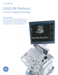
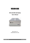
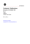
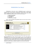
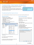
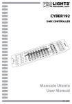
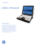
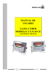
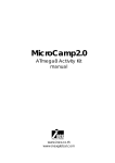
PERFORM Operating Document
Use and Maintenance of G.E. Ultrasound
LOGIC E
PC-POD-IM-001-v01
Revision History
Version
01
Reason for Revision
Date
New POD
22/May/2013
Summary
The content of this PERFORM Operating Document (POD) provides guidelines for the
quality control, image acquisition, and maintenance of the G.E. Ultrasound LOGIC E.
PC-POD-IM-001-v01
Printed copies are not controlled.
Page 2 of 15
Table of Contents
SUMMARY --------------------------------------------------------------------------------------------2
1. LIST OF ABBREVIATIONS -----------------------------------------------------------------4
2. INTRODUCTION -----------------------------------------------------------------------------5
2.1 OVERVIEW OF G.E. ULTRASOUND LOGIC E -----------------------------------------5
2.2 RESPONSIBILITY -------------------------------------------------------------------------------5
3. PROCEDURE ------------------------------------------------------------------------------------5
3.1 QUALIFICATION OF PERSONNEL -------------------------------------------------------5
3.2 TRAINING---------------------------------------------------------------------------------------5
3.3 OPERAITION -----------------------------------------------------------------------------------5
3.3.1 IMPORTANT SAFETY CONSIDERATION----------------------------------------------5
3.3.2 SYSTEM POWER -----------------------------------------------------------------------------6
3.3.3 STARTING AN EXAM ----------------------------------------------------------------------8
3.3.4 B/M MODE IMAGE OPTIMIZE ----------------------------------------------------------10
3.3.5 B MODE CONTROL PANEL CONTROLS -------------------------------------------11
3.3.6 COLOR FLOW/DOPPLER IMAGE OPTIMIZE----------------------------------------11
3.3.7 SCANNING HINTS ------------------------------------------------------------------------12
3.3.8 IMAGE MANAGEMENT-------------------------------------------------------------------14
APPENDIX I: Probe Immersion
APPENDIX II: POD Training Record Form
PC-POD-IM-001-v01
Printed copies are not controlled.
Page 3 of 15
1. Definition of Terms
ARDMS
American Registry for Diagnostic Medical Sonography
ATO
Auto Tissue Optimization
AVI
Audio Video Interleave
CAMRT
A national certifying body for medical imaging technologist
professionals
CAO
Chief Administration Officer
CFM
Color Flow Mode
CWD
Continuous Wave Doppler
DICOM
Digital Imaging and Communications in Medicine
Diode
Diode is a two-terminal electronic component with an
asymmetric transfer characteristic
LED
Light Emitting Diode
JPG
Joint Photographic Experts Group
Logic e
LOGIC e Ultrasound brand from GE Healthcare
MSK
Musculoskeletal
PDI
Power Doppler Imaging
PI
Principal Investigator
POD
PERFORM Operating Document
PRF
Pules Repetition Frequency
PWD
Pulsed Wave Doppler
PYROGEN
Is a substance inducing fever
ROI
Region of Interest
TGC
Time Gain Compensation
USB
Is a data storage device that includes flash memory with an
integrated Universal Serial Bus (USB) interface.
PC-POD-IM-001-v01
Printed copies are not controlled.
Page 4 of 15
2. Introduction
This POD is designed to outline the use, maintenance and training needs for the G.E.
Ultrasound LOGIC E.
2.1 Overview of G.E. Ultrasound LOGIC E
An evolving technology with wide applications in imaging through medical/surgical and
research practices such as Cardiac, Vascular, Neurological, MSK, OB/GYN, and Urology
studies.
2.2 Responsibility
It is the responsibility of all users and supervisor to ensure that this POD is followed.
3. Procedure
3.1 Qualification of Personnel
Scans may be performed by a technologist (certified by ARDMS /CAMRT) or by
a physician. Other research personnel performing ultrasound scans may do so
after initial and ongoing training by a certified sonographer or physician and at
the discretion of the principal investigator.
3.2 Training
Basic theoretical training is a pre-requisite for any practical training. All users should
receive proper training in applications and instrumentation. Users should never modify
the equipment.
3.3 Operation
3.3.1 Important Safety Considerations
The following topic headings (Participant Safety, and Equipment and Personnel Safety)
are intended to make the equipment user aware of particular hazards associated with
the use of this equipment and the extent to which injury can occur if precautions are
not observed.
CAUTION
Improper use can result in serious injury. The user must be thoroughly familiar with the
instructions and potential hazards involving ultrasound examination before attempting to
use the device. Training assistance is available from GE Medical Systems if needed.
The equipment user is obligated to be familiar with these concerns and avoid conditions
that could result in injury.
PC-POD-IM-001-v01
Printed copies are not controlled.
Page 5 of 15
Incorrect Setting
Equipment malfunction or incorrect settings can result in measurement errors or failure
to detect details within the image. The equipment user must become thoroughly familiar
with the equipment operation in order to optimize its performance and recognize
possible malfunctions.
3.3.2 System Power
Connect the system to the electrical supply and turn the power on. LED indicators,
Indicates hard disk working status. When the LED is flashing, the system is writing or
reading from the hard disk (Green). The orange LED will turn on when the battery is
low.
LOGIC e Control Panel Tour
1- TGC. Move slide pots left/right to adjust TGC.
2- New Patient. Press to activate these controls.
3- Additional Feature Keys: Steer, Harmonics, PDI.
4- Mode/Gain/Auto Keys: M Mode, Pulsed Wave Doppler (PW) Modes, Color Flow
(CF) Mode and B Mode. Press these key to activate the mode; rotate the key to
adjust the Gain; Press Auto to activate/deactivate auto optimization.
5- Imaging/Measurement Key: Cursor, Clear, Body Mark Measure, M/D Cursor,
Scan Area, Set / B. Press these keys, as necessary.
6- Depth/Zoom/Ellipse. Adjust these keys, as necessary.
7- Start/Stop.
8- Print Keys: Press the P1, P2, P3 keys to archive, print, or send the image.
9- Freeze. Press Freeze to freeze the image or return to scanning.
PC-POD-IM-001-v01
Printed copies are not controlled.
Page 6 of 15
10- Keyboard. Use the keyboard to enter patient information and annotations. Press
F1, F2, F3, F4, F5 and F12 keys to activate Online help/User Manual, Arrow,
Eject, Spooler, Reverse and Touch Panel Mode On/Off functions. The User can
define functions for the F6-F11 keys.
The following functions are available for F7- F12 Keys:
CWD, 3D, LOGIC View, CrossXBeam, ECG On/Off, Set Home, Text Overlay,
Work Sheet, Grab Last, Word Delete and Video.DVR. Press [Utility] to enter
the Utility function and configure the system. Press [Preset] to preset the
system. Press [Report] to Enter the report page.
LOGIC e Keys, Soft Menu Key Tour
In general, there are two types of soft Menu keys: Paddle Switch and adjustable knobs.
1- The Paddle Switch is used to access and adjust the Sub Soft Menu.
2- Press the adjustable knobs to toggle option menu between line one and line two.
3- Rotate the adjustable knobs to adjust the corresponding parameters.
Function Keys - Programmable Keys
• F1 = Help (Enter Online Help / User Manual)
• F2 = Arrow (Annotation Arrow)
• F3 = Eject (Eject media)
• F4 = Spooler (Activates DICOM Job Spooler screen)
• F5 = Reverse
• F6-F11 Programmable
• F12 = Touch Panel Mode On/Off
How to Program your programmable keys
<Utility> - <Admin> - <Function Key>, <Key Configuration> then use the drop down
menu.
Choices for program Keys
Shortcut keys
• CWD
• Ctrl + Alt + R: Restart the system
• 3D
• Ctrl + E: Eject
• LOGIC View
• Ctrl + Alt + V: Output Video
PC-POD-IM-001-v01
Printed copies are not controlled.
Page 7 of 15
• CrossXBeam
• ECG On/Off
• Set Home
• Text Overlay
• Grab Last • Word Delete
• Video.DVR
How to Program your hot keys
<Utility> - <Admin> - <Function Key>, <Hot Key> then use the drop down menu.
Choices for hot keys
No function - Biopsy Guide - Save as - Active Image - Measurement Select - Auto
Doppler Calculation - Auto Trace - DVD Format - Range Focus - OB Graph
Measurement All Clear – ATO - Auto TGC - Print4 - Print5
3.3.3 Starting an Exam
New Patient
To start a new patient’s exam:
1. Press Patient. Press the New Patient button on the Patient menu.
2. Select the Exam Category.
3. Type the Patient ID, Patient Name, Birthdate, etc.
4. Press the Register button on the Patient menu (DO NOT press Register if you are
automatically generating a patient ID).
5. Press B, Esc, or Exit.
Patient Entry Menu
Image Management Window [1]
Access to this patient’s exam history and image management features.
Function Selection Window [2]
New Patient is used to clear the patient entry screen to input a new patient’s data into
thedatabase.
Register is used to enter new patient information into the database prior to the actual
exam being performed. Details displays exam details and additional patient information.
PC-POD-IM-001-v01
Printed copies are not controlled.
Page 8 of 15
EZBackup, EZMove[3]
One-step method to backup (move and delete p patient images) to an external media.
Dataflow [4]
Selects this exam’s dataflow preference.
Exit [5]
Exits the Patient Menu and returns to scanning.
Patient Information [6]
Patient ID, Name, Birthdate, Age and Sex.
Category Selection and Exam Information [7&8]
Select the appropriate category and enter the exam information.
Patient View and Exam View [9]
Patient View lists the patients in the database. “Search key” enables searching list by
Patient ID, Last Name, First Name, Birthdate, Sex, Exam today, Exam between, Exam
date before, Exam date, Exam date after, Accession Number and
Exam Description. “string” field helps define the search parameters, and “Clear“ clears
the searching condition. Exam View lists the exams of the selected patient. Select the
patient or the exam in Patient View and press “Exam View”.
PC-POD-IM-001-v01
Printed copies are not controlled.
Page 9 of 15
3.3.4 B/M Mode Image Optimize
Power Output
Optimizes image quality and allows user to reduce beam intensity. 2% increments
between 0-100%.
Dynamic Range
Dynamic Range controls how echo intensities are converted to shades of gray, thereby
increasing the adjustable range of contrast.
Focus Number and Position
Increases the number of transmit focal zones or moves the focal zone(s) so that you can
tighten up the beam for a specific area. A graphic caret corresponding to the focal zone
position(s) appears on the right edge of the image.
NOTE: Push key to toggle between Focus Number and Focus Position.
NOTE: Not available when Auto frequency/Autodepth active.
Rejection
Selects a level below which echoes will not be amplified (an echo must have a certain
minimum amplitude before it will be processed).
Edge Enhance
Edge Enhance brings out subtle tissue differences and boundaries by enhancing the gray
scale differences corresponding to the edges of structures. Adjustments to M Mode's
edge enhancement affects the M Mode only.
Frame Average
Temporal filter that averages frames together. This has the effect of presenting a
smoother, softer image.
Colorize
Enables gray scale image colorization. To deactivate, reselect a Gray Map.
Gray Map
Determines how the echo intensity levels received are presented as shades of gray.
Rotation (Up/Down)
Rotates the image by selecting the value from the Soft key.
PC-POD-IM-001-v01
Printed copies are not controlled.
Page 10 of 15
Frequency
Multi Frequency mode lets you downshift to the probe's next lower frequency or shift
up to a higher frequency.
Line density
Optimizes B Mode frame rate or spatial resolution for the best possible image.
3.3.5 B Mode Control Panel Controls
Auto Optimize
Automatic Tissue Optimization optimizes the image based upon a specified Region of
Interest (ROI) or anatomy within the display.
Zoom
Magnifies a zoom region of interest, which is magnified to approximately the size of a
full-sized image. An un-zoomed reference image is displayed adjacent to the zoom
window. The system adjusts all imaging parameters accordingly. Press Depth/
Zoom/Ellipse key to activate Zoom. Adjust the key to increase or decrease the zoom
size. Use the Trackball to position the Zoom ROI. Only when the zoom size reaches
the max or press the Depth/ Zoom/Ellipse key again would deactivate the Zoom, and
activate Depth.
Reverse
Flips the image left/right.
Range Focus
Improves the near/mid field image quality, borders/ interfaces, increases contrast and
detail resolution across the image, and allows for less filling in the vessels.
3.3.6 Color Flow/Doppler Image Optimize
Baseline
Adjusts the baseline to accommodate faster or slower blood flows to eliminate aliasing.
PRF/Wall Filter
Velocity scale determines pulse repetition frequency. If the sample volume gate range
exceeds single gate PRF capability, the system automatically switches to high PRF mode.
Multiple gates appear, and HPRF is indicated on the display. Wall Filter insulates the
Doppler signal from excessive noise caused from vessel movement.
NOTE: Push button to toggle between PRF and Wall Filter.
PC-POD-IM-001-v01
Printed copies are not controlled.
Page 11 of 15
Angle Correct
Estimates the flow velocity in a direction at an angle to the Doppler vector by
computing the angle between the Doppler vector and the flow to be measured.
Quick Angle
Quickly adjust the angle by 60 degrees.
Threshold
Threshold assigns the gray scale level at which color information stops.
Doppler Display Formats
Display layout can be preset to have B-Mode and Time-motion side-by-side or overunder.
Sample Volume Gate Length
Sizes the sample volume gate.
Map
Allows a specific color map to be selected. After a selection has been made, the color
bar displays the resultant map.
Packet Size
Controls the number of samples gathered for a single color flow vector.
Controls in Common with B Mode
For more information on Focal Zone, Power Output, Frequency, Frame Average,
Dynamic Range, Gray Map, and Colorize, refer to the B/M Mode Image Optimize
section in this Quick Guide.
3.3.7 Scanning Hints
Line Density.
Trades frame rate for sensitivity and spatial resolution. If the frame rate is too slow,
reduce the size of the region of interest, select a different line density setting, or reduce
the packet size.
Wall Filter.
Affects low flow sensitivity versus motion artifact.
To improve sensitivity:
1- Increase the Gain.
2- Decrease the PRF.
PC-POD-IM-001-v01
Printed copies are not controlled.
Page 12 of 15
3456789-
Increase the Power Output.
Adjust the Line Density.
Decrease the Wall Filter.
Increase Frame Average.
Increase the Packet Size.
Reduce the ROI to the smallest reasonable size.
Position the Focal Zones properly.
To decrease motion artifact:
1- Increase the PRF.
2- Increase the Wall Filter.
To eliminate aliasing:
1- Increase the PRF.
2- Lower the Baseline.
For venous imaging:
1- Ensure that you have selected the vascular exam category.
2- Select a venous application.
3- Select the appropriate probe for very superficial structure.
4- Select two focal zones.
5- Adjust the depth to the anatomy to be imaged.
6- Maintain a low gain setting for gray scale.
7- Activate Color Flow.
8- Maintain the PRF at a lower setting.
9- Increase Frame Averaging for more persistence.
CFM Top/Sub Menu Controls
PC-POD-IM-001-v01
PWD Top/Sub Menu Controls
Printed copies are not controlled.
Page 13 of 15
Probe Cleaning, After Each Use
1- Disconnect probe from ultrasound console and remove all coupling gel from
probe by wiping with a soft cloth and rinsing with flowing water.
2- Wash the probe with mild soap in lukewarm water. Scrub the probe as needed
using a soft sponge, gauze, or cloth to remove all visible residue from the probe
surface. Prolonged soaking or scrubbing with a soft bristle brush (such as a
toothbrush) may be necessary if material has dried onto the probe surface.
3- Rinse the probe with enough clean potable water to remove all visible soap
residue.
4- Air dry or dry with a soft cloth.
Probe Disinfection, After Each Use
1- Prepare the germicide solution according to the manufacturer's instructions. Be
sure to follow all precautions for storage, use and disposal.
2- Place the cleaned and dried probe in contact with the germicide for the time
specified by the germicide manufacturer. High-level disinfection is recommended
for surface probes and is required for endocavitary and intraoperative probes
3- (follow the germicide manufacturer's recommended time). Probes for neuro
surgical intra-operative use must NOT be sterilized with liquid chemical sterilants
because of the possibility of neuro toxic residues remaining on the probe.
Neurological procedures must be done with the
use of legally marketed, sterile, pyrogen free probe sheaths.
4- After removing from the germicide, rinse the probe following the germicide
manufacturer's rinsing instructions. Flush all visible germicide residue from the
probe and allow to air dry (Appendix I).
Probe Disinfection Agents
Ultrasound probes can be disinfected using liquid chemical germicides. The level of
disinfection is directly related to the duration of contact with the germicide. Increased
contact time produces a higher level of disinfection.
Review the probe care card that is packed with each probe. The following website
contains the most current and up-to-date recommendations:
http://www.gehealthcare.com/usen/ultrasound/ products/probe_case.html
3.3.8 Image Management
Clipboard
As images are saved by pressing any of the print keys (P1, P2, or P3), the images appear
at the bottom of the display on the clipboard as thumbnails of the images saved during
the exam. These images remain on the clipboard until the end of the exam.
PC-POD-IM-001-v01
Printed copies are not controlled.
Page 14 of 15
Printing Images
Press the appropriate print key (P1, P2, P3).
Browsing an Exam’s Stored Images
From the New Patient menu, open Image History. View the thumbnail images for the
past exam or group images.
Managing an Exam’s Stored Images
From the New Patient menu, open Active Images. View active exam images.
Deleting an Image
Select the image on the clipboard, then press the onscreen Delete shortcut or
From the New Patient menu, select the image from the Review Screen of Image
Management, then press Delete.
Save Image to USB Memory Stick
The brand validated is:
1- Kingston 512MB USB To use them the user needs to do the following:
2- Insert them into a free USB port.
3- Click on the Menu option from the right side of the screen.
4- Click Save As.
5- Select the Removable disk drive.
6- Select File Type (DICOM, JPG or AVI).
7- Provide File-Name and press Save.
Note: Before pulling out the memory stick, the device should be stopped, by clicking on the EjectHardware Icon (see following figure), selecting the device, and pressing Stop.
PC-POD-IM-001-v01
Printed copies are not controlled.
Page 15 of 15
APPENDIX I
Probe Immersion Levels
PC-POD-IM-001-v01
Printed copies are not controlled.
Page 16 of 15
Probe Immersion Levels
1. Fluid Level
2. Aperture
3. Contact face within patient environment
CAUTION
In order for liquid chemical germicides to be effective, all visible residue must be removed during the
cleaning process. Thoroughly clean the probe, as described earlier before attempting disinfection.
You MUST disconnect the probe from the LOGIC e prior to cleaning/disinfecting the probe. Failure to
do so could damage the system.
PC-POD-GA-001-v01
Printed copies are not controlled.
ii
APPENDIX II
POD Training Record Form
PC-POD-GA-001-v01
Printed copies are not controlled.
ii
POD Title
Use and Maintenance of G.E. Ultrasound LOGIC E
SOP Code
Ownership
Document type
Area
SOP Number
Version
PC
POD
IM
001
v01
Training Record
Full Name
Institution
Contact
(email or phone number)
Signature
Sign here
PC-POD-GA-001-v01
Date
Printed copies are not controlled.
ii