1
Preface
SIMATIC HMI WinCC flexible 2008 WinCC flexible 2008 Communication Part 2
SIMATIC HMI
WinCC flexible 2008
Communication Part 2
User's Manual
This user manual is part of the documentation
package with the order number
6AV6691-1CA01-3AB0.
07/2008
A5E01067260-02
Working with connections
1
Communication with
Allen-Bradley controllers
2
Communication with
GE Fanuc controllers
3
Communication with
LG controllers
4
Communication with
Mitsubishi controllers
5
Communication with
Modicon controllers
6
Communication with
Omron controllers
7
Appendix
8
Safety Guidelines
This manual contains notices you have to observe in order to ensure your personal safety, as well as to prevent
damage to property. The notices referring to your personal safety are highlighted in the manual by a safety alert
symbol, notices referring only to property damage have no safety alert symbol. These notices shown below are
graded according to the degree of danger.
DANGER
indicates that death or severe personal injury will result if proper precautions are not taken.
WARNING
indicates that death or severe personal injury may result if proper precautions are not taken.
CAUTION
with a safety alert symbol, indicates that minor personal injury can result if proper precautions are not taken.
CAUTION
without a safety alert symbol, indicates that property damage can result if proper precautions are not taken.
NOTICE
indicates that an unintended result or situation can occur if the corresponding information is not taken into
account.
If more than one degree of danger is present, the warning notice representing the highest degree of danger will
be used. A notice warning of injury to persons with a safety alert symbol may also include a warning relating to
property damage.
Qualified Personnel
The device/system may only be set up and used in conjunction with this documentation. Commissioning and
operation of a device/system may only be performed by qualified personnel. Within the context of the safety notes
in this documentation qualified persons are defined as persons who are authorized to commission, ground and
label devices, systems and circuits in accordance with established safety practices and standards.
Prescribed Usage
Note the following:
WARNING
This device may only be used for the applications described in the catalog or the technical description and only
in connection with devices or components from other manufacturers which have been approved or
recommended by Siemens. Correct, reliable operation of the product requires proper transport, storage,
positioning and assembly as well as careful operation and maintenance.
Trademarks
All names identified by ® are registered trademarks of the Siemens AG. The remaining trademarks in this
publication may be trademarks whose use by third parties for their own purposes could violate the rights of the
owner.
Disclaimer of Liability
We have reviewed the contents of this publication to ensure consistency with the hardware and software
described. Since variance cannot be precluded entirely, we cannot guarantee full consistency. However, the
information in this publication is reviewed regularly and any necessary corrections are included in subsequent
editions.
Siemens AG
Industry Sector
Postfach 48 48
90327 NÜRNBERG
GERMANY
Ordernumber: 6AV6691-1CA01-3AB0
Ⓟ 07/2008
Copyright © Siemens AG 2008.
Technical data subject to change
Safety Guidelines
Preface
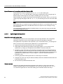
Purpose of this manual
This user manual is part of the WinCC flexible documentation..
The purpose of the "WinCC flexible Communication" user manual is to explain:
● which communications protocols can be used for communication between a SIEMENS
HMI device and a controller,
● which SIEMENS HMI devices can be used for communication,
● which controllers can be connected to a selected SIEMENS HMI device,
● which settings are required in the controller program for the connection, and
● which user data areas must be set up for communication.
Separate sections therefore explain the size, structure, and function of the user data areas
and the assigned area pointers.
The manual is intended for newcomers, operators and configuration engineers involved in
configuration, commissioning, installation and service with WinCC flexible.
The help integrated in WinCC flexible, the WinCC flexible Information System, contains
detailed information. The information system contains instructions, examples and reference
information in electronic form.
Basic Knowledge Requirements
General knowledge in the field of automation engineering is required to understand this
manual.
You should also have experience of using PCs running under the Windows 2000 or
Windows XP operating systems. A knowledge of VBA or VBS is required for advanced
configuration by using scripts.
Scope of the manual
This manual is valid for the WinCC flexible 2008 software package.
Position in the information scheme
This manual is part of the SIMATIC HMI documentation. The information below presents an
overview of the information landscape of SIMATIC HMI.
WinCC flexible 2008 Communication Part 2
User's Manual, 07/2008, 6AV6691-1CA01-3AB0
3
Preface
User manual
● WinCC flexible Micro
– describes the engineering basics based on the WinCC flexible Micro engineering
system (ES)
● WinCC flexible Compact/ Standard/ Advanced
– describes the engineering basics based on the WinCC flexible Compact,
WinCC flexible Standard and WinCC flexible Advanced engineering systems (ES)
● WinCC flexible Runtime:
– Describes how to commission and operate your Runtime project on a PC.
● WinCC flexible Migration:
– Describes how to convert an existing ProTool project to WinCC flexible.
– Describes how to convert an existing WinCC project to WinCC flexible.
– Describes how to migrate ProTool projects with an HMI migration from OP3 to OP 73
or OP 73 micro.
– Describes how to migrate ProTool projects with an HMI migration from OP7 to OP 77B
or OP 77A.
– Describes how to migrate ProTool projects with an HMI migration from OP17 to
OP 177B.
– describes how to migrate ProTool projects with HMI migration from RMOS graphic
devices to Windows CE devices.
● Communication:
– Communication Part 1 describes the connection of the HMI device to SIMATIC PLCs.
– Communication Part 2 describes the connection of the HMI device to third-party PLCs.
Operating Instructions
● Operating instructions for SIMATIC HMI devices:
– OP 73, OP 77A, OP 77B
– TP 170micro, TP 170A, TP 170B, OP 170B
– OP 73micro, TP 177micro
– TP 177A, TP 177B, OP 177B
– TP 270, OP 270
– MP 270B
– MP 370
● Operating instructions for mobile SIMATIC HMI devices:
– Mobile Panel 170
● Operating instructions (compact) for SIMATIC HMI devices:
– OP 77B
– Mobile Panel 170
4
WinCC flexible 2008 Communication Part 2
User's Manual, 07/2008, 6AV6691-1CA01-3AB0
Preface
Getting Started
● WinCC flexible for first time users:
– Based on a sample project, this is a step-by-step introduction to the basics of
configuring screens, alarms, and recipes, and screen navigation.
● WinCC flexible for advanced users:
– Based on a sample project, this is a step-by-step introduction to the basics of
configuring logs, project reports, scripts, user management, and multilingual projects,
and integration into STEP 7.
● WinCC flexible options:
– Based on a sample project, this is a step-by-step introduction to the basics of
configuring the WinCC flexible Audit, Sm@rtServices, Sm@rtAccess and OPC Server
options.
Online availability
The following link actively guides you to technical documentation for SIMATIC products and
systems in different languages.
● SIMATIC Guide Technical Documentation:
http://www.automation.siemens.com/simatic/portal/html_76/techdoku.htm
Guide
The user manual consists of Parts 1 and 2. Part 2 is organized as follows:
● the connection to Allen-Bradley controllers,
● the connection to GE Fanuc Automation controllers,
● the connection to LG Industrial Systems/IMO controllers,
● the connection to Mitsubishi Electric controllers,
● the connection to Schneider Automation (Modicon) controllers,
● the connection to OMRON controllers.
Part 1 contains the descriptions of
● the connection to SIEMENS SIMATIC controllers (S7, S5, 500/505)
● the connection via the HMI HTTP protocol
● the connection via OLE for Process Control (OPC)
● the connection to SIMOTION controllers
● the connection to WinAC controllers
WinCC flexible 2008 Communication Part 2
User's Manual, 07/2008, 6AV6691-1CA01-3AB0
5
Preface
Conventions
A distinction is made in the naming conventions for the configuration and runtime software:
● "WinCC flexible 2008" refers to the configuration software.
● "Runtime" designates the runtime software running on the HMI devices.
● "WinCC flexible Runtime" designates the visualization product for use on standard PCs or
panel PCs.
The term "WinCC flexible" is used in the general context. A version name such as
"WinCC flexible 2008" is used whenever it is necessary to distinguish it from other versions.
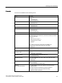
The following formatting is used to facilitate reading of the manual:
Notation
Scope
"Add screen"
•
•
•
Terminology that occurs in the user interface, e.g., dialog
names, tabs, buttons, menu commands.
Inputs required, e.g., limit values, tag values
Path information
"File > Edit"
Operational sequences, e.g., menu commands/shortcut menu
commands.
<F1>, <Alt>+<P>
Keyboard inputs
Please observe notes labeled as follows:
Note
Notes containing important information about the product and its use or a specific section of
the documentation to which you should pay particular attention.
Trademarks
HMI®
SIMATIC®
SIMATIC HMI®
SIMATIC ProTool®
SIMATIC WinCC®
SIMATIC WinCC flexible®
Third parties using for their own purposes any other names in this document which refer to
trademarks might infringe upon the rights of the trademark owners.
6
WinCC flexible 2008 Communication Part 2
User's Manual, 07/2008, 6AV6691-1CA01-3AB0
Preface
Additional support
Representatives and offices
If you have questions concerning the use of the described product which are not answered in
this manual, please contact the Siemens representative in your area.
Find your contact partner at:
http://www.siemens.com/automation/partner
A guide to the technical documentation for the various SIMATIC products and systems is
available at:
http://www.siemens.com/simatic-tech-doku-portal
The online catalog and the online ordering system is available at:
http://mall.automation.siemens.com
Training center
To familiarize you with automation systems, we offer a variety of courses. Please contact
your regional training center or the central training center in D-90327 Nuremberg, Germany.
Phone: +49 (911) 895-3200
Internet: http://www.sitrain.com
Technical support
You can reach the technical support for all A&D products
via the support request form on the web:
http://www.siemens.com/automation/support-request
Phone: + 49 180 5050 222
Fax: + 49 180 5050 223
Additional information about our technical support is available in the Internet at:
http://www.siemens.com/automation/service
WinCC flexible 2008 Communication Part 2
User's Manual, 07/2008, 6AV6691-1CA01-3AB0
7
Preface
Service & support on the Internet
In addition to our documentation, we offer our complete knowledge base on the Internet at.
http://www.siemens.com/automation/service&support
There you will find:
● The newsletter which provides the latest information on your products.
● Relevant documentation for your application, which you can access via the search
function in our service & support database.
● A forum where users and experts from all over ther world exchange ideas.
● You local Automation & Drives representative.
● Information about on-site service, repairs, spare parts. Much more can be found on our
"Services" pages.
8
WinCC flexible 2008 Communication Part 2
User's Manual, 07/2008, 6AV6691-1CA01-3AB0
Table of contents
Preface ...................................................................................................................................................... 3
1
2
Working with connections ........................................................................................................................ 15
1.1
1.1.1
1.1.2
Basics...........................................................................................................................................15
Communication basics.................................................................................................................15
Principles of communication ........................................................................................................16
1.2
1.2.1
1.2.2
1.2.3
Elements and basic settings ........................................................................................................18
Connections Editor.......................................................................................................................18
Parameters for connections .........................................................................................................19
Area pointers for connections ......................................................................................................20
1.3
Configuring the connection ..........................................................................................................21
1.4
Connections and protocols ..........................................................................................................22
1.5
1.5.1
1.5.2
1.5.3
1.5.4
1.5.5
1.5.6
Device-based dependency ..........................................................................................................24
Device-dependency of the protocols ...........................................................................................24
Device-based dependency of the interfaces................................................................................29
Device/based dependency of area pointers ................................................................................36
Device-based dependency of alarms ..........................................................................................38
Device-based dependency of direct keys ....................................................................................40
Device-based dependency of interfaces for the project transfer .................................................41
1.6
Conversion when changing controllers........................................................................................43
Communication with Allen-Bradley controllers ......................................................................................... 45
2.1
2.1.1
2.1.2
2.1.3
Communication with Allen-Bradley ..............................................................................................45
Communication between the HMI device and the PLC (Allen-Bradley) ......................................45
Communication peers for the DF1 and DH485 Protocol (Allen-Bradley) ....................................46
Communication peer for the Allen-Bradley E/IP C.Logix protocol ...............................................47
2.2
2.2.1
2.2.1.1
2.2.1.2
2.2.1.3
2.2.1.4
2.2.1.5
2.2.1.6
2.2.1.7
2.2.2
2.2.2.1
2.2.2.2
2.2.2.3
2.2.2.4
2.2.2.5
2.2.2.6
2.2.2.7
2.2.3
Configuring the Allen-Bradley communication driver...................................................................48
Communication via DF1 protocol.................................................................................................48
Requirements of communication .................................................................................................48
Installing the communication driver..............................................................................................51
Configuring the controller type and protocol ................................................................................51
Configuring protocol parameters..................................................................................................51
Permitted data types (Allen-Bradley DF1) ...................................................................................53
Optimizing the configuration ........................................................................................................54
Commissioning components (Allen-Bradley DF1) .......................................................................55
Communication via DH485 protocol ............................................................................................57
Requirements of communication .................................................................................................57
Installing the communication driver..............................................................................................59
Configuring the controller type and protocol ................................................................................61
Configuring protocol parameters..................................................................................................62
Permitted data types (Allen-Bradley DH485)...............................................................................63
Optimizing the configuration ........................................................................................................64
Commissioning components (Allen-Bradley DH485) ..................................................................65
Communication via Allen-Bradley Ethernet IP.............................................................................67
WinCC flexible 2008 Communication Part 2
User's Manual, 07/2008, 6AV6691-1CA01-3AB0
9
Table of contents
3
10
2.2.3.1
2.2.3.2
2.2.3.3
2.2.3.4
2.2.3.5
2.2.3.6
Communication requirements (Allen-Bradley Ethernet IP) ......................................................... 67
Installing the communication driver (Allen-Bradley Ethernet IP)................................................. 67
Configuring the PLC type and protocol (Allen-Bradley Ethernet IP)........................................... 67
Configuring protocol parameters (Allen-Bradley Ethernet IP)..................................................... 68
Examples: Communication path ................................................................................................. 69
Valid data types and addressing................................................................................................. 69
2.3
2.3.1
2.3.2
2.3.3
2.3.3.1
2.3.3.2
2.3.3.3
2.3.3.4
2.3.3.5
2.3.3.6
2.3.3.7
2.3.3.8
2.3.4
2.3.4.1
2.3.4.2
2.3.4.3
2.3.4.4
User data areas........................................................................................................................... 78
Trend request and trend transfer ................................................................................................ 78
LED mapping .............................................................................................................................. 80
Area pointer................................................................................................................................. 81
General information on area pointers (Allen-Bradley) ................................................................ 81
"Screen number" area pointer..................................................................................................... 83
"Date/time" area pointer .............................................................................................................. 84
"Date/time controller" area pointer .............................................................................................. 85
"Coordination" area pointer ......................................................................................................... 86
"Project ID" area pointer.............................................................................................................. 87
"Job mailbox" area pointer .......................................................................................................... 87
"Data mailbox" area pointer ........................................................................................................ 90
Events, alarms, and acknowledgments ...................................................................................... 97
General information on events, alarms, and acknowledgments ................................................. 97
Step 1: Creating tags or an array................................................................................................ 98
Step 2: Configuring an alarm .................................................................................................... 100
Step 3: Configure the acknowledgment .................................................................................... 102
2.4
2.4.1
2.4.2
2.4.3
2.4.4
2.4.5
2.4.6
2.4.7
2.4.8
2.4.9
2.4.10
2.4.11
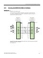
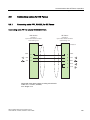
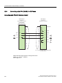
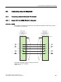
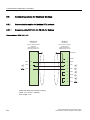
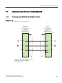
Connecting cables for Allen-Bradley......................................................................................... 104
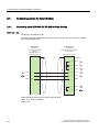
Connecting cable 6XV1440-2K, RS 232 for Allen-Bradley ....................................................... 104
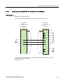
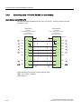
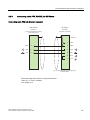
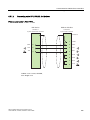
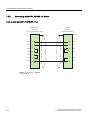
Connecting cable 6XV1440-2L, RS 232, for Allen-Bradley ...................................................... 105
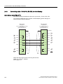
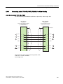
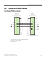
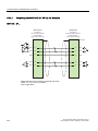
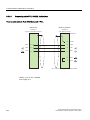
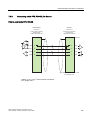
Connecting cable 1784-CP10, RS 232, for Allen-Bradley ........................................................ 106
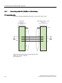
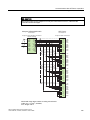
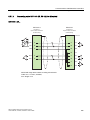
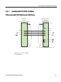
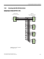
Connecting cable 6XV1440-2V, RS 422, for Allen-Bradley ...................................................... 107
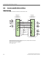
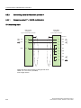
Connecting cable 1747-CP3, RS-232, for Allen-Bradley .......................................................... 108
Connecting cable 1761-CBL-PM02, RS-232, for Allen-Bradley ............................................... 109
Connecting cable PP1, RS-232, for Allen-Bradley ................................................................... 110
Connecting cable PP2, RS-232, for Allen-Bradley ................................................................... 111
Connecting cable PP3, RS-232, for Allen-Bradley ................................................................... 112
Connecting cable PP4, RS-485, for Allen-Bradley ................................................................... 113
Connecting cable MP1, RS-485, for Allen-Bradley................................................................... 114
Communication with GE Fanuc controllers ............................................................................................ 115
3.1
3.1.1
3.1.2
Communication with GE Fanuc ................................................................................................ 115
Communication partner (GE Fanuc) ......................................................................................... 115
Communication between HMI device and controller (GE Fanuc)............................................. 115
3.2
3.2.1
3.2.2
3.2.3
3.2.4
3.2.5
3.2.6
Configuring the communication driver for GE Fanuc................................................................ 116
Requirements of communication .............................................................................................. 116
Installing the communication driver........................................................................................... 118
Configuring the controller type and protocol ............................................................................. 118
Configuring protocol parameters............................................................................................... 118
Permitted data types (GE Fanuc) ............................................................................................. 120
Optimizing the configuration ..................................................................................................... 121
3.3
3.3.1
3.3.2
3.3.3
3.3.3.1
3.3.3.2
3.3.3.3
User data areas......................................................................................................................... 122
Trend request and trend transfer .............................................................................................. 122
LED mapping ............................................................................................................................ 124
Area pointer............................................................................................................................... 125
General information on area pointers (GE FANUC) ................................................................. 125
"Screen number" area pointer................................................................................................... 127
"Date/time" area pointer ............................................................................................................ 128
WinCC flexible 2008 Communication Part 2
User's Manual, 07/2008, 6AV6691-1CA01-3AB0
Table of contents
4
3.3.3.4
3.3.3.5
3.3.3.6
3.3.3.7
3.3.3.8
3.3.4
3.3.4.1
3.3.4.2
3.3.4.3
3.3.4.4
"Date/time controller" area pointer .............................................................................................129
"Coordination" area pointer........................................................................................................130
"Project ID" area pointer ............................................................................................................131
"Job mailbox" area pointer .........................................................................................................131
"Data mailbox" area pointer .......................................................................................................134
Events, alarms, and acknowledgments .....................................................................................141
General information on events, alarms, and acknowledgments................................................141
Step 1: Creating tags or an array...............................................................................................142
Step 2: Configuring an alarm .....................................................................................................143
Step 3: Configure the acknowledgment.....................................................................................145
3.4
3.4.1
Commissioning components......................................................................................................147
Commissioning components......................................................................................................147
3.5
3.5.1
3.5.2
3.5.3
3.5.4
3.5.5
3.5.6
3.5.7
3.5.8
Connecting cables for GE Fanuc ...............................................................................................149
Connecting cable PP1, RS-232, for GE Fanuc..........................................................................149
Connecting cable PP2, RS-232, for GE Fanuc..........................................................................150
Connecting cable PP3, RS-232, for GE Fanuc..........................................................................151
Connecting cable PP4, RS-232, for GE Fanuc..........................................................................152
Connecting cable PP5, RS-232, for GE Fanuc..........................................................................153
Connecting cable PP6, RS-232, for GE Fanuc..........................................................................154
Connection cable MP1, RS 422, for GE Fanuc .........................................................................154
Connection cable MP2, RS 422, for GE Fanuc .........................................................................156
Communication with LG controllers ....................................................................................................... 157
4.1
4.1.1
4.1.2
Communication with LG GLOFA-GM ........................................................................................157
Communication partner (LG GLOFA) ........................................................................................157
Communication between HMI device and controller (LG GLOFA)............................................158
4.2
4.2.1
4.2.2
4.2.3
4.2.4
4.2.5
4.2.6
Configuring the LG GLOFA-GM communication driver .............................................................158
Requirements of communication ...............................................................................................158
Installing the communication driver............................................................................................159
Configuring the controller type and protocol ..............................................................................159
Configuring protocol parameters................................................................................................160
Permitted data types (LG GLOFA).............................................................................................161
Optimizing the configuration ......................................................................................................163
4.3
4.3.1
4.3.2
4.3.3
4.3.3.1
4.3.3.2
4.3.3.3
4.3.3.4
4.3.3.5
4.3.3.6
4.3.3.7
4.3.3.8
4.3.4
4.3.4.1
4.3.4.2
4.3.4.3
4.3.4.4
User data areas .........................................................................................................................164
Trend request and trend transfer ...............................................................................................164
LED mapping .............................................................................................................................166
Area pointer................................................................................................................................167
General information on area pointers (LG GLOFA-GM)............................................................167
"Screen number" area pointer....................................................................................................169
"Date/time" area pointer.............................................................................................................170
"Date/time controller" area pointer .............................................................................................171
"Coordination" area pointer........................................................................................................172
"Project ID" area pointer ............................................................................................................173
"Job mailbox" area pointer .........................................................................................................173
"Data mailbox" area pointer .......................................................................................................176
Events, alarms, and acknowledgments .....................................................................................183
General information on events, alarms, and acknowledgments................................................183
Step 1: Creating tags or an array...............................................................................................184
Step 2: Configuring an alarm .....................................................................................................185
Step 3: Configure the acknowledgment.....................................................................................187
4.4
4.4.1
Commissioning components......................................................................................................189
Commissioning components (communications modules) .........................................................189
4.5
Connecting cables for LG GLOFA-GM ......................................................................................191
WinCC flexible 2008 Communication Part 2
User's Manual, 07/2008, 6AV6691-1CA01-3AB0
11
Table of contents
4.5.1
4.5.2
4.5.3
4.5.4
4.5.5
4.5.6
5
12
Connecting cable PP1, RS-232, for LG/IMO ............................................................................ 191
Connecting cable PP2, RS-422, for LG/IMO ............................................................................ 192
Connecting cable PP3, RS-485, for LG/IMO ............................................................................ 193
Connecting cable PP4, RS-232, for LG/IMO ............................................................................ 194
Connecting cable MP1, RS-485, for LG/IMO............................................................................ 195
Connecting cable MP2, RS-422, for LG/IMO............................................................................ 196
Communication with Mitsubishi controllers ............................................................................................ 197
5.1
5.1.1
5.1.2
Communication with Mitsubishi MELSEC ................................................................................ 197
Communication partner (Mitsubishi MELSEC) ......................................................................... 197
Communication between the HMI device and controller (Mitsubishi)....................................... 198
5.2
5.2.1
5.2.2
5.2.3
5.2.4
5.2.5
5.2.6
5.2.7
Communication via PG protocol ............................................................................................... 199
Requirements of communication .............................................................................................. 199
Installing the communication driver........................................................................................... 200
Configuring the controller type and protocol ............................................................................. 200
Configuring protocol parameters............................................................................................... 201
Permitted data types (Mitsubishi PG) ....................................................................................... 202
Optimizing the configuration ..................................................................................................... 203
Commissioning components ..................................................................................................... 205
5.3
5.3.1
5.3.2
5.3.3
5.3.4
5.3.5
5.3.6
5.3.7
Communication via protocol 4................................................................................................... 206
Requirements of communication .............................................................................................. 206
Installing the communication driver........................................................................................... 207
Configuring the controller type and protocol ............................................................................. 207
Configuring protocol parameters............................................................................................... 208
Permitted data types (Mitsubishi Protocol 4) ............................................................................ 210
Optimizing the configuration ..................................................................................................... 212
Commissioning components ..................................................................................................... 213
5.4
5.4.1
5.4.2
5.4.3
5.4.3.1
5.4.3.2
5.4.3.3
5.4.3.4
5.4.3.5
5.4.3.6
5.4.3.7
5.4.3.8
5.4.4
5.4.4.1
5.4.4.2
5.4.4.3
5.4.4.4
User data areas......................................................................................................................... 214
Trend request and trend transfer .............................................................................................. 214
LED mapping ............................................................................................................................ 216
Area pointer............................................................................................................................... 217
General information on area pointers (Mitsubishi MELSEC) .................................................... 217
"Screen number" area pointer................................................................................................... 219
"Date/time" area pointer ............................................................................................................ 220
"Date/time controller" area pointer ............................................................................................ 221
"Coordination" area pointer ....................................................................................................... 222
"User version" area pointer ....................................................................................................... 223
"Job mailbox" area pointer ........................................................................................................ 223
"Data mailbox" area pointer ...................................................................................................... 226
Events, alarms, and acknowledgments .................................................................................... 233
General information on events, alarms, and acknowledgments ............................................... 233
Step 1: Creating tags or an array.............................................................................................. 234
Step 2: Configuring an alarm .................................................................................................... 235
Step 3: Configure the acknowledgment .................................................................................... 237
5.5
5.5.1
5.5.1.1
5.5.1.2
5.5.1.3
5.5.2
5.5.2.1
5.5.2.2
5.5.2.3
5.5.2.4
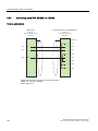
Connecting cables for Mitsubishi .............................................................................................. 239
Connecting cables for Mitsubishi PG protocol .......................................................................... 239
Adapter 6XV1440-2UE32, RS-232, for Mitsubishi.................................................................... 239
Connecting cable 6XV1440-2P, RS-422, for Mitsubishi ........................................................... 240
Connecting cable 6XV1440-2R, RS-422, for Mitsubishi ........................................................... 241
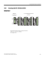
Connecting cable for Mitsubishi protocol 4 ............................................................................... 242
Connecting cable PP1, RS-232, for Mitsubishi ......................................................................... 242
Connecting cable PP2, RS-232, for Mitsubishi ......................................................................... 243
Connecting cable PP3, RS-232, for Mitsubishi ......................................................................... 244
Connecting cable PP4, RS-232, for Mitsubishi ......................................................................... 245
WinCC flexible 2008 Communication Part 2
User's Manual, 07/2008, 6AV6691-1CA01-3AB0
Table of contents
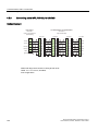
5.5.2.5
5.5.2.6
5.5.2.7
6
7
Connecting cable PP5, RS-232, for Mitsubishi..........................................................................246
Connecting cable MP3, RS-232, over converter, for Mitsubishi ................................................247
Connecting cable MP2, RS-422, for Mitsubishi .........................................................................248
Communication with Modicon controllers............................................................................................... 249
6.1
6.1.1
6.1.2
Communication with Modicon Modbus ......................................................................................249
Communication partner (Modicon Modbus)...............................................................................249
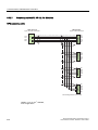
Communication between HMI device and controller (Modicon) ................................................253
6.2
6.2.1
6.2.2
6.2.3
6.2.4
6.2.5
6.2.6
6.2.7
Communication via Modbus RTU protocol ................................................................................254
Requirements of communication ...............................................................................................254
Installing the communication driver............................................................................................255
Configuring the PLC type and protocol......................................................................................255
Configuring protocol parameters................................................................................................256
Permitted data types (Modbus RTU) .........................................................................................257
Optimizing the configuration ......................................................................................................258
Commissioning components......................................................................................................259
6.3
6.3.1
6.3.2
6.3.3
6.3.4
6.3.5
6.3.6
6.3.7
Communication via Modbus TCP/IP protocol ............................................................................261
Requirements of communication ...............................................................................................261
Installing the communication driver............................................................................................261
Configuring the PLC type and protocol......................................................................................261
Configuring protocol parameters................................................................................................262
Permitted data types (Modbus TCP/IP) .....................................................................................263
Optimizing the configuration ......................................................................................................264
Commissioning components......................................................................................................265
6.4
6.4.1
6.4.2
6.4.3
6.4.3.1
6.4.3.2
6.4.3.3
6.4.3.4
6.4.3.5
6.4.3.6
6.4.3.7
6.4.3.8
6.4.4
6.4.4.1
6.4.4.2
6.4.4.3
6.4.4.4
User data areas .........................................................................................................................267
Trend request and trend transfer ...............................................................................................267
LED mapping .............................................................................................................................269
Area pointer................................................................................................................................270
General information on area pointers (Modicon Modbus) .........................................................270
"Screen number" area pointer....................................................................................................272
"Date/time" area pointer.............................................................................................................273
"Date/time controller" area pointer .............................................................................................274
"Coordination" area pointer........................................................................................................275
"Project ID" area pointer ............................................................................................................276
"PLC job" area pointer ...............................................................................................................276
"Data mailbox" area pointer .......................................................................................................279
Events, alarms, and acknowledgments .....................................................................................286
General information on operational messages, alarm messages and acknowledgments ........286
Step 1: Creating tags or an array...............................................................................................287
Step 2: Configuring an alarm .....................................................................................................288
Step 3: Configuring the acknowledgment ..................................................................................290
6.5
6.5.1
6.5.1.1
6.5.1.2
6.5.1.3
6.5.1.4
Connecting cables for Modicon Modbus....................................................................................292
Communication cables for Modbus RTU protocol .....................................................................292
Connecting cable 6XV1440-1K, RS-232, for Modicon ..............................................................292
Connecting cable PP1, RS-232, for Modicon ............................................................................293
Connecting cable PP2, RS-232, for Modicon ............................................................................294
Connecting cable PP3, RS-232, for Modicon ............................................................................295
Communication with Omron controllers ................................................................................................. 297
7.1
7.1.1
7.1.2
Communication with Omron Hostlink/Multilink...........................................................................297
Communication partner (Omron) ...............................................................................................297
Communication between HMI device and controller (Omron)...................................................297
7.2
Configuring the communication driver Omron Hostlink/Multilink ...............................................298
WinCC flexible 2008 Communication Part 2
User's Manual, 07/2008, 6AV6691-1CA01-3AB0
13
Table of contents
8
7.2.1
7.2.2
7.2.3
7.2.4
7.2.5
7.2.6
Requirements for communication (Omron)............................................................................... 298
Installing the communication driver........................................................................................... 299
Configuring the controller type and protocol (Omron)............................................................... 299
Configuring protocol parameters (Omron) ................................................................................ 300
Permitted data types (Omron)................................................................................................... 301
Optimizing the configuration ..................................................................................................... 303
7.3
7.3.1
7.3.2
7.3.3
7.3.3.1
7.3.3.2
7.3.3.3
7.3.3.4
7.3.3.5
7.3.3.6
7.3.3.7
7.3.3.8
7.3.4
7.3.4.1
7.3.4.2
7.3.4.3
7.3.4.4
User data areas......................................................................................................................... 304
Trend request and trend transfer .............................................................................................. 304
LED mapping ............................................................................................................................ 306
Area pointer............................................................................................................................... 307
General information on area pointers (Omron Hostlink/Multilink) ............................................. 307
"Screen number" area pointer................................................................................................... 309
"Date/time" area pointer ............................................................................................................ 310
"Date/time controller" area pointer ............................................................................................ 311
"Coordination" area pointer ....................................................................................................... 312
"Project ID" area pointer (Omron) ............................................................................................. 313
"Job mailbox" area pointer ........................................................................................................ 313
"Data mailbox" area pointer ...................................................................................................... 316
Events, alarms, and acknowledgments .................................................................................... 323
General information on events, alarms, and acknowledgments ............................................... 323
Step 1: Creating tags or an array.............................................................................................. 324
Step 2: Configuring an alarm .................................................................................................... 325
Step 3: Configure the acknowledgment .................................................................................... 327
7.4
7.4.1
Commissioning components ..................................................................................................... 329
Commissioning components ..................................................................................................... 329
7.5
7.5.1
7.5.2
7.5.3
7.5.4
7.5.5
Connecting cables for Omron Hostlink/Multilink ....................................................................... 331
Connecting cable 6XV1440-2X, RS-232, for Omron ................................................................ 331
Connecting cable PP1, RS-232, for Omron .............................................................................. 332
Connecting cable PP2, RS-422, for Omron .............................................................................. 333
Connecting cable MP1, RS-232, over converter, for Omron .................................................... 334
Connecting cable MP2, RS-422, for Omron ............................................................................. 335
Appendix................................................................................................................................................ 337
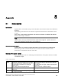
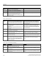
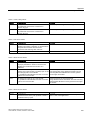
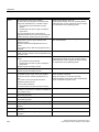
8.1
System alarms .......................................................................................................................... 337
8.2
Abbreviations ............................................................................................................................ 369
8.3
Glossary .................................................................................................................................... 371
Index...................................................................................................................................................... 375
14
WinCC flexible 2008 Communication Part 2
User's Manual, 07/2008, 6AV6691-1CA01-3AB0
Working with connections
1.1
Basics
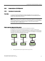
1.1.1
Communication basics
1
Introduction
The data exchange between two communication partners is known as communication. The
communication partners can be interconnected via direct cable connection or network.
Communication partners
A communication partner can be any node which is capable of communicating and
exchanging data with other nodes on the network. In the WinCC flexible environment, the
following nodes can be communication partners:
● Central modules and communication modules in the automation system
● can be HMI devices and communication processors in the PC.
Data transferred between the communication partners may serve different purposes:
● process control
● process data acquisition
● reporting states in a process
● process data logging
WinCC flexible 2008 Communication Part 2
User's Manual, 07/2008, 6AV6691-1CA01-3AB0
15
Working with connections
1.1 Basics
1.1.2
Principles of communication
Introduction
WinCC flexible controls communication between the HMI and the PLC by means of tags and
area pointers.
Communication using tags
In WinCC flexible, tags are centrally managed in the "Tag" editor. There are external and
internal tags. External tags are used for communication, and represent the image of defined
memory locations on the PLC. The HMI and the PLC both have read and write access to this
storage location. Those read and write operations may cyclic or event-triggered.
In your configuration, create tags that point to specific PLC addresses. The HMI reads the
value from the defined address, and then displays it. The operator may also enter values on
the HMI device which will be written to the relevant PLC address.
Communication using area pointers
Area pointers are used to exchange data of specific user data areas. Area pointers are
parameter fields. WinCC flexible receives from these parameter fields in runtime the
information about the location and size of data areas in the PLC. During communication, the
PLC and the HMI device alternately access those data areas for read and write operations.
Based on the evaluation of data stored in the data areas, the PLC and HMI device trigger
defined actions.
WinCC flexible uses the following area pointers:
● Control request
● Project ID
● Screen number
● Data record
● Date/time
● Date/time PLC
● Coordination
The availability of the various area pointers is determined by the HMI used.
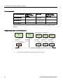
Communication between WinCC flexible and automation systems
Industrial communication using WinCC flexible means that data are exchanged using tags
and area pointers. To acquire the data, the HMI sends request messages to the automation
system using a communication driver. The automation system (AS) returns the requested
data to the HMI in a response frame.
16
WinCC flexible 2008 Communication Part 2
User's Manual, 07/2008, 6AV6691-1CA01-3AB0
Working with connections
1.1 Basics
Communication drivers
A communication driver is a software component that develops a connection between an
automation system and an HMI device. The communication driver hence enables the tags in
WinCC flexible to be supplied with process values. WinCC flexible supports the
interconnection of different automation systems with various communication drivers.
Users can select the interface, the profile and the transmission speed for each specific
communication partner.
Communication between HMIs
The SIMATIC HMI HTTP Protocol is available for the communication between HMIs. This
protocol is a component of the "Sm@rtAccess" option. The protocol can be used on PCs
with WinCC flexible Runtime and on Panels as of the 270 series. For detailed information,
refer to the SIMATIC HMI HTTP Protocol documentation.
Communication via uniform and manufacturer-independent interface
WinCC flexible provides a uniform and manufacturer-independent software interface using
OPC (OLE for Process Control). This interface allows a standardized data exchange
between applications for industry, office, and production. For detailed information, refer to
the OPC documentation.
WinCC flexible 2008 Communication Part 2
User's Manual, 07/2008, 6AV6691-1CA01-3AB0
17
Working with connections
1.2 Elements and basic settings
1.2
Elements and basic settings
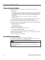
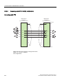
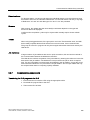
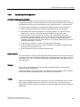
1.2.1
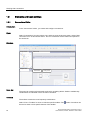
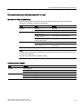
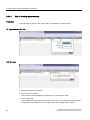
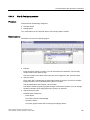
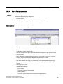
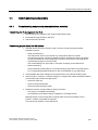
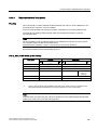
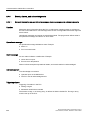
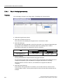
Connections Editor
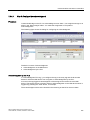
Introduction
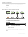
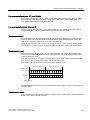
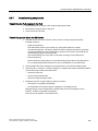
In the "Connections" editor, you create and configure connections.
Open
Select "Connections" from the project view, and then open the shortcut menu. Select "New
connection" from in this shortcut menu. The new connection will be created and opened in
the work area.
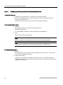
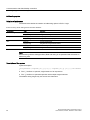
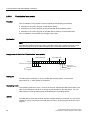
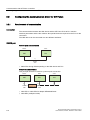
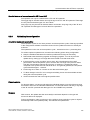
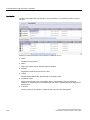
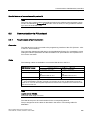
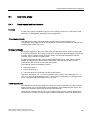
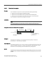
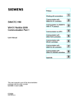
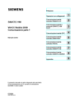
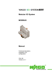
Structure
3URMHFWYLHZ
:RUNDUHD
2EMHFWYLHZ
3DUDPHWHUV
Menu bar
Toolbars
$UHDSRLQWHU
The menu bar contains all commands required for operating WinCC flexible. Available key
combinations are indicated next to the menu command.
The toolbars contain the most frequently used buttons.
Select "View > Toolbars" to show or hide the specific toolbars. The
button of a toolbar can
be used to show or hide specific buttons of this toolbar.
18
WinCC flexible 2008 Communication Part 2
User's Manual, 07/2008, 6AV6691-1CA01-3AB0
Working with connections
1.2 Elements and basic settings
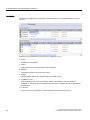
Work area
All connections are visualized in the work area in tabular format. You select the
communication drivers from the table cells, and edit the relevant connection properties. To
sort the table by its column entries, simply click the column header.
"Parameters" tab
Using the "Parameters" tab you can configure the settings for the communication drivers
selected in the table. Select the settings for the HMI, the network and for the PLC.
"Area pointer" tab
Using the "Area pointers" tab you can configure the area pointers of the connections.
1.2.2
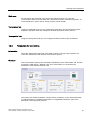
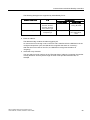
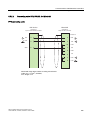
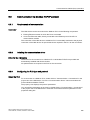
Parameters for connections
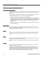
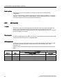
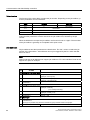
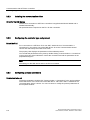
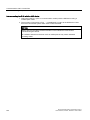
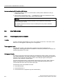
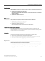
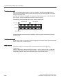
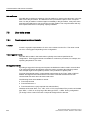
Introduction
Select the "Parameters" tab of the "Connections" editor to configure the properties of a
connection between the HMI and the communication partner.
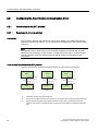
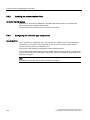
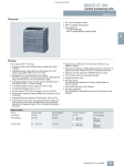
Structure
The communication partners are visualized schematically on the "Parameters" tab. This tab
provides the "HMI device", "Network" and "PLC" areas where you can declare the
parameters of the relevant interface used.
The system sets default parameters. Always ensure consistency on the network whenever
you edit parameters. For detailed information on configurable parameters, refer to the
description of the supported protocols.
WinCC flexible 2008 Communication Part 2
User's Manual, 07/2008, 6AV6691-1CA01-3AB0
19
Working with connections
1.2 Elements and basic settings
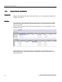
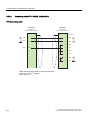
1.2.3
Area pointers for connections
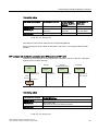
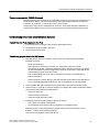
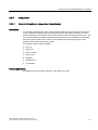
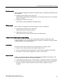
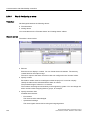
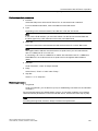
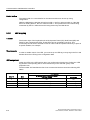
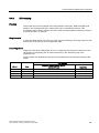
Introduction
Using the "Area pointer" tab of the "Connections" editor, you can configure the usage of the
available area pointers.
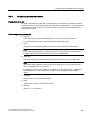
Structure
The "Area pointer" tab contains two tables of area pointers. The "For all connections" table
contains those area pointers which are created only once in the project and can be used for
only one connection.
The "For each connection" table contains the area pointers you can set separately for each
available connection.
The availability of the various area pointers is determined by the HMI device used. For
detailed information on area pointers and their configuration, refer to the description of the
supported protocols.
20
WinCC flexible 2008 Communication Part 2
User's Manual, 07/2008, 6AV6691-1CA01-3AB0
Working with connections
1.3 Configuring the connection
1.3
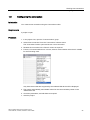
Configuring the connection
Introduction
You create a new connection using the Connections editor.
Requirements
A project is open.
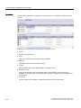
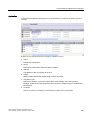
Procedure
1. In the project view, open the "Communication" group.
2. Select "New connection" from the "Connections" shortcut menu.
The "Connections" editor opens and shows a new connection.
3. Rename the connection in the "Name" column as required.
4. From the "Communication driver" column, select a communication driver that is suitable
for the PLC being used.
Only those drivers that are supported by the selected HMI device will be displayed.
5. The system automatically sets suitable values for the communication partner in the
"Parameters" tab.
6. Check the parameters, and edit these as required.
7. Save the project.
WinCC flexible 2008 Communication Part 2
User's Manual, 07/2008, 6AV6691-1CA01-3AB0
21
Working with connections
1.4 Connections and protocols
Alternative procedure
Select "Insert > New item > Connection" from the menu bar. The "Connections" editor opens
and shows a new connection. Edit the connection as described in steps 2 through 7.
You can drag-and-drop existing connections directly from HMI_1 or via an interim station in
the library to HMI_2. The output view shows the following information: "The interface used for
the connection has been adapted to the device". A device change is performed for this
connection. The system does not verify whether or not the HMI_2 supports the
communications driver.
Open the "Connections" editor on HMI_2 to check the connections. Faulty entries are
marked in orange.
Result
1.4
A new connection was created. The connection parameters are configured.
Connections and protocols
HMI functionality
The HMI is used to read, save and record alarms and tags. In addition, the HMI can be used
to intervene in the process.
CAUTION
Ethernet communication
In Ethernet-based communication, such as PROFINET IO, HTTP, Sm@rtAccess,
Sm@rtService and OPC, it is the end user who is responsible for the security of his data
network. The proper functioning of the device cannot be guaranteed in all circumstances;
targeted attacks, for example, can lead to an overloading of the device.
Data exchange
The prerequisite for the operating and monitoring functions is the connection of the HMI
device to a PLC. Data exchange between the HMI and the PLC is controlled by a
connection-specific protocol. Each connection requires a separate protocol.
Criteria for selecting the connection
Criteria for selecting the connection between the HMI and the PLC are, for example:
● PLC type
● CPU in the PLC
● HMI device type
● Number of HMI devices per PLC
● Structure and any bus systems of an existing plant
● Amount of components additionally required
22
WinCC flexible 2008 Communication Part 2
User's Manual, 07/2008, 6AV6691-1CA01-3AB0
Working with connections
1.4 Connections and protocols
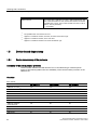
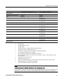
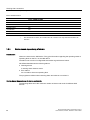
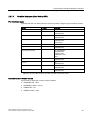
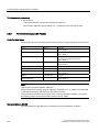
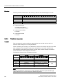
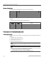
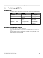
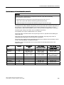
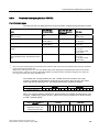
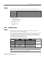
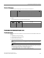
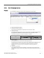
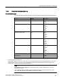
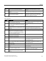
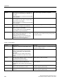
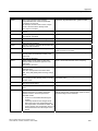
Protocols
Protocols are available for the following PLCs:
PLC
Protocol
SIMATIC S7
•
•
•
•
PPI
MPI 1)
PROFIBUS DP
TCP/IP (Ethernet)
SIMATIC S5
•
•
AS 511
PROFIBUS DP
SIMATIC 500/505
•
•
NITP
PROFIBUS DP
SIMATIC HMI HTTP Protocol
•
HTTP/HTTPS (Ethernet)
SIMOTION
•
•
•
MPI
PROFIBUS DP
TCP/IP (Ethernet)
OPC
•
DCOM
Allen-Bradley
PLC series SLC500, SLC501, SLC502, SLC503, SLC504,
SLC505, MicroLogix and PLC5/11, PLC5/20, PLC5/30, PLC5/40,
PLC5/60, PLC5/80
• DF1 2)
• DH+ via KF2 module 3)
• DH485 via KF3 module 4)
• DH485 4)
PLC series ControlLogix 5500 (with 1756-ENBT) and
CompactLogix 5300 (1769-L32E and 1769-L35E)
• Ethernet
GE Fanuc Automation
SPS series 90–30, 90–70, VersaMax Micro
• SNP
LG Industrial Systems (Lucky
Goldstar) / IMO
PLC series GLOFA GM (GM4, GM6 and GM7) / Series G4, G6
and G7
• Dedicated communication
Mitsubishi Electric
PLC series MELSEC FX and MELSEC FX0
• FX (Mitsubishi PG)
Mitsubishi Electric
PLC series MELSEC FX0, FX1n, FX2n, AnA, AnN, AnS, AnU,
QnA and QnAS
• Protocol 4
OMRON
PLC series SYSMAC C, SYSMAC CV, SYSMAC CS1, SYSMAC
alpha, CJ and CP
• Hostlink/Multilink (SYSMAC Way)
Modicon
(Schneider Automation)
PLC series Modicon 984, TSX Quantum and TSX Compact
• Modbus RTU
SPS series Quantum, Momentum, Premium and Micro
SPS series Compact and 984 via Ethernet bridge
• Modbus TCP/IP (Ethernet)
WinCC flexible 2008 Communication Part 2
User's Manual, 07/2008, 6AV6691-1CA01-3AB0
23
Working with connections
1.5 Device-based dependency
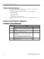
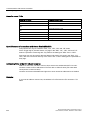
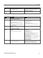
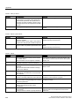
PLC
Protocol
Telemecanique
PLC series TSX 7 with P47 411, TSX 7 with P47/67/87/107 420,
TSX 7 with P47/67/87/107 425, module TSX SCM 21.6 with the
specified TSX 7 CPUs, TSX 17 with module SCG 1161, TSX 37
(Micro), TSX 57 (Premium)
• Uni-Telway
1)
Not possible when connected to S7-212.
2)
Applies to controllers SLC503, SLC504, SLC505, PLC5, MicroLogix
3)
Applies to controllers SLC504, PLC5 over DF1
4)
Applies to controllers SLC500 to SLC 505 and MicroLogix
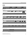
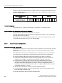
1.5
Device-based dependency
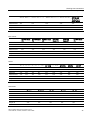
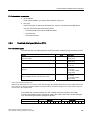
1.5.1
Device-dependency of the protocols
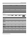
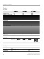
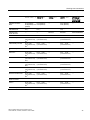
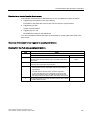
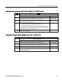
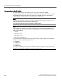
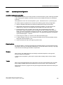
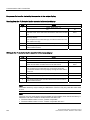
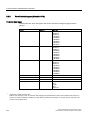
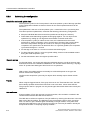
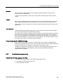
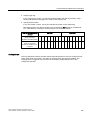
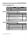
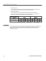
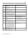
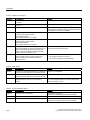
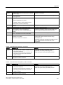
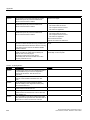
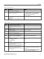
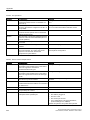
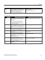
Availability of the communication protocols
Communication between the HMI and the PLC is controlled using a network-specific
protocol. The following tables show the availability of the communication protocols on the
HMI devices.
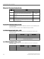
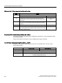
Overview
Micro Panels
OP 73micro 1)
TP 170micro 1)
TP 177micro 1)
SIMATIC S7 - PPI 1)
Yes
Yes
Yes
SIMATIC S7 - MPI 1)
Yes
Yes
Yes
SIMATIC S7 - PROFIBUS-DP 1)
Yes
Yes
Yes
SIMATIC S7 - PROFINET
No
No
No
SIMATIC S5 - AS511
No
No
No
SIMATIC S5 - PROFIBUS DP
No
No
No
SIMATIC 500/505 - NITP
No
No
No
SIMATIC 500/505 PROFIBUS DP
No
No
No
SIMATIC HMI HTTP Protocol
No
No
No
OPC
No
No
No
SIMOTION
No
No
No
24
WinCC flexible 2008 Communication Part 2
User's Manual, 07/2008, 6AV6691-1CA01-3AB0
Working with connections
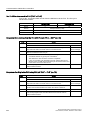
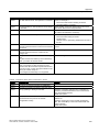
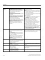
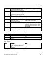
1.5 Device-based dependency
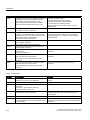
OP 73micro 1)
TP 170micro 1)
TP 177micro 1)
Allen-Bradley DF1
No
No
No
Allen-Bradley DH 485
No
No
No
Allen-Bradley Ethernet IP
No
No
No
GE Fanuc
No
No
No
LG GLOFA-GM
No
No
No
Mitsubishi FX
No
No
No
Mitsubishi P4
No
No
No
Modicon Modbus RTU
No
No
No
Modicon Modbus TCP/IP
No
No
No
Omron
No
No
No
Telemecanique
No
No
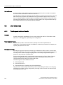
No
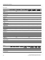
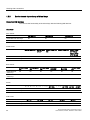
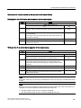
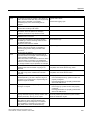
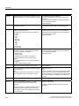
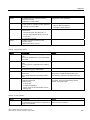
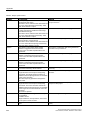
Mobile Panels
Mobile Panel 170 Mobile Panel
177 DP
Mobile Panel
177 PN
Mobile Panel
277 4)
Mobile Panel
277 IWLAN
Mobile Panel
277F IWLAN
SIMATIC S7 - PPI 1)
Yes
Yes
No
Yes
No
SIMATIC S7 - MPI
Yes
Yes
No
Yes
No
SIMATIC S7 PROFIBUS DP
Yes
Yes
No
Yes
No
SIMATIC S7 PROFINET
No
No
Yes
Yes
Yes
SIMATIC S5 - AS511
Yes
No
No
yes 3)
No
SIMATIC S5 PROFIBUS DP
Yes
Yes
No
Yes
No
SIMATIC 500/505 NITP
Yes
Yes
No
Yes
No
SIMATIC 500/505 PROFIBUS DP
Yes
Yes
No
Yes
No
SIMATIC HMI
HTTP Protocol
No
No
Yes
Yes
Yes
OPC
No
No
No
Yes
Yes
SIMOTION
Yes
Yes
Allen-Bradley DF1
Yes
Allen-Bradley DH 485
Allen-Bradley Ethernet
IP
Yes
Yes
Yes
7) 8)
No
Yes
Yes
7) 8)
No
No
No
Yes
GE Fanuc
Yes
Yes 7) 8)
LG GLOFA-GM
Mitsubishi FX
No
Yes
7) 8)
No
Yes
7) 8)
No
Yes 7) 8)
Yes 7)
No
Yes 7) 8)
No
Yes
Yes
7) 8)
No
Yes
7) 8)
No
Yes
Yes 7) 8)
No
Yes 7) 8)
No
Mitsubishi P4
Yes
Yes
7) 8)
No
Yes
7) 8)
No
Modicon Modbus RTU
Yes
Yes
7) 8)
No
Yes
7) 8)
No
WinCC flexible 2008 Communication Part 2
User's Manual, 07/2008, 6AV6691-1CA01-3AB0
7)
25
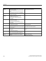
Working with connections
1.5 Device-based dependency
Mobile Panel 170 Mobile Panel
177 DP
Mobile Panel
177 PN
Mobile Panel
277 4)
Mobile Panel
277 IWLAN
Mobile Panel
277F IWLAN
Modicon
Modbus TCP/IP
No
No
Yes
Yes 7) 8)
No
Omron
Yes
Yes 7) 8)
No
Yes 7) 8)
No
Telemecanique
Yes
Yes
No
Yes
No
7) 8)
7)
7) 8)
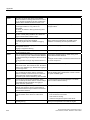
Basic Panels
KTP400
Basic PN
KTP600 Basic
DP
KTP600 Basic
PN 11)
KTP1000
Basic DP
KTP1000
Basic PN
TP1500 Basic
PN
SIMATIC S7 - PPI 1) No
Yes
No
Yes
No
No
SIMATIC S7 - MPI
No
Yes
No
Yes
No
No
SIMATIC S7 PROFIBUS DP
No
Yes
No
Yes
No
No
SIMATIC S7 PROFINET
Yes
No
Yes
No
Yes
Yes
SIMATIC S5 AS511
No
No
No
No
No
No
SIMATIC S5 PROFIBUS DP
No
No
No
No
No
No
SIMATIC 500/505 NITP
No
No
No
No
No
No
SIMATIC 500/505 PROFIBUS DP
No
No
No
No
No
No
SIMATIC HMI
HTTP Protocol
No
No
No
No
No
No
OPC
No
No
No
No
No
No
SIMOTION
No
No
No
No
No
No
Allen-Bradley DF1
No
Yes 10)
No
Yes 10)
No
No
Allen-Bradley
DH 485
No
No
No
No
No
No
Allen-Bradley
Ethernet IP
No
No
No
No
No
No
GE Fanuc
No
No
No
No
No
No
LG GLOFA-GM
No
No
No
No
No
No
Mitsubishi FX
No
No
No
No
No
No
Mitsubishi P4
No
No
No
No
No
No
Modicon
Modbus RTU
No
Yes 5)
No
Yes 5)
No
No
Modicon
Modbus TCP/IP
No
No
No
No
No
No
Omron
No
No
No
No
No
No
Telemecanique
No
No
No
No
No
No
26
WinCC flexible 2008 Communication Part 2
User's Manual, 07/2008, 6AV6691-1CA01-3AB0
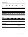
Working with connections
1.5 Device-based dependency
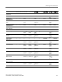
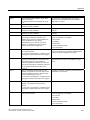
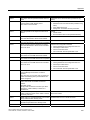
Panels
OP 73 OP 77A OP 77B 9) TP 170A 9) TP 170B TP 177A
OP 170B
TP 177B 9) TP 270
OP 177B 9) OP 270
TP 277 9)
OP 277 9)
SIMATIC S7 - PPI 1)
Yes
Yes
Yes 8)
Yes
Yes
Yes
Yes
Yes
Yes
SIMATIC S7 - MPI
Yes
Yes
Yes
Yes
Yes
Yes
Yes
Yes
Yes
SIMATIC S7 PROFIBUS DP
Yes
Yes
Yes
Yes
Yes
Yes
Yes
Yes
Yes
SIMATIC S7 PROFINET
No
No
No
No
Yes
No
Yes
Yes
Yes
SIMATIC S5 AS511
No
No
Yes
Yes
Yes
No
No
Yes
No
SIMATIC S5 PROFIBUS DP
No
No
Yes
No
Yes
No
Yes
Yes
Yes
SIMATIC 500/505 NITP
No
No
Yes
Yes
Yes
No
Yes
Yes
Yes
SIMATIC 500/505 PROFIBUS DP
No
No
Yes
No
Yes
No
Yes
Yes
Yes
SIMATIC HMI
HTTP Protocol
No
No
No
No
No
No
Yes 6)
Yes
Yes
OPC
No
No
No
No
No
No
No
No
No
SIMOTION
No
No
No
No
Yes
No
Yes
Yes
Yes
Allen-Bradley DF1
No
Yes 10)
Yes 9)
Yes 9)
Yes
Yes 10)
Yes 7) 9) 10)
Yes
Yes 7) 9)
Allen-Bradley
DH 485
No
No
Yes 9)
Yes 9)
Yes
No
Yes
7) 9)
Yes
Yes
7) 9)
Allen-Bradley
Ethernet IP
No
No
No
No
No
No
Yes
6) 7)
No
Yes
7)
GE Fanuc
No
No
Yes 9)
Yes 9)
Yes
No
Yes
7) 9)
Yes
Yes
7) 9)
LG GLOFA-GM
No
No
Yes 9)
Yes 9)
Yes
No
Yes 7) 9)
Yes
Yes 7) 9)
Mitsubishi FX
No
No
Yes 9)
Yes 9)
Yes
No
Yes 7) 9)
Yes
Yes 7) 9)
Mitsubishi P4
No
No
Yes
Yes
9)
Yes
No
Yes
Yes
Yes 7) 9)
Modicon
Modbus RTU
No
Yes 5)
Yes 9)
Yes 9)
Yes
Yes 5)
Yes 5) 7) 9)
Yes
Yes 5) 7) 9)
Modicon
Modbus TCP/IP
No
No
No
No
No
No
Yes 6) 7)
Yes
Yes 7)
Omron
No
No
Yes 9)
Yes 9)
Yes
No
Yes 7) 9)
Yes
Yes 7) 9)
Telemecanique
No
No
Yes 9)
Yes 9)
Yes
No
Yes 7) 9)
Yes
Yes 7) 9)
9)
6)
7) 9)
10)
Multi Panels
MP 177 9)
MP 270B
MP 277 9)
MP 370
MP377 9)
Yes
Yes
Yes
Yes
Yes
SIMATIC S7 - MPI
Yes
Yes
Yes
Yes
Yes
SIMATIC S7 PROFIBUS DP
Yes
Yes
Yes
Yes
Yes
SIMATIC S7 - PPI
1)
WinCC flexible 2008 Communication Part 2
User's Manual, 07/2008, 6AV6691-1CA01-3AB0
27
Working with connections
1.5 Device-based dependency
MP 177 9)
MP 270B
MP 277 9)
MP 370
MP377 9)
SIMATIC S7 PROFINET
Yes
Yes
Yes
Yes
Yes
SIMATIC S5 - AS511
No
Yes
No
Yes
No
SIMATIC S5 PROFIBUS DP
Yes
Yes
Yes
Yes
Yes
SIMATIC 500/505 NITP
Yes
Yes
Yes
Yes
Yes
SIMATIC 500/505 PROFIBUS DP
Yes
Yes
Yes
Yes
Yes
SIMATIC HMI
HTTP Protocol
Yes
Yes
Yes
Yes
Yes
OPC
No
Yes
Yes
Yes
Yes
SIMOTION
No
Yes
Yes
Yes
Yes
Allen-Bradley DF1
Yes 7) 9) 10)
Yes
Yes 7) 9) 10)
Yes
Yes 7) 9) 10)
Allen-Bradley DH 485
Yes 7) 9)
Yes
Yes 7) 9)
Yes
Yes 7) 9)
Allen-Bradley
Ethernet IP
Yes 7) 9)
Yes
Yes 7) 9)
Yes
Yes 7) 9)
GE Fanuc
Yes 7) 9)
Yes
Yes 7) 9)
Yes
Yes 7) 9)
LG GLOFA-GM
Yes 7) 9)
Yes
Yes 7) 9)
Yes
Yes 7) 9)
Mitsubishi FX
Yes 7) 9)
Yes
Yes 7) 9)
Yes
Yes 7) 9)
Mitsubishi P4
Yes 7) 9)
Yes
Yes 7) 9)
Yes
Yes 7) 9)
Modicon
Modbus RTU
Yes
Yes
Yes
Yes
Yes 5) 7) 9)
Modicon
Modbus TCP/IP
Yes 7) 9)
Yes
Yes 7) 9)
Yes
Yes 7) 9)
Omron
Yes 7) 9)
Yes
Yes 7) 9)
Yes
Yes 7) 9)
Telemecanique
Yes 7) 9)
Yes
Yes 7) 9)
Yes
Yes 7) 9)
5) 7) 9)
5) 7) 9)
WinCC flexible Runtime
WinCC flexible Runtime
SIMATIC S7 - PPI 1)
Yes
SIMATIC S7 - MPI
Yes
SIMATIC S7 - PROFIBUS DP
Yes
SIMATIC S7 - PROFINET
Yes
SIMATIC S5 - AS511
Yes
SIMATIC S5 - PROFIBUS DP
Yes
SIMATIC 500/505 - NITP
Yes
SIMATIC 500/505 PROFIBUS DP
Yes
SIMATIC HMI HTTP Protocol
Yes
OPC
Yes
SIMOTION
Yes
28
WinCC flexible 2008 Communication Part 2
User's Manual, 07/2008, 6AV6691-1CA01-3AB0
Working with connections
1.5 Device-based dependency
WinCC flexible Runtime
Allen-Bradley DF1
Yes
Allen-Bradley DH 485
Yes
Allen-Bradley Ethernet IP
Yes
GE Fanuc
Yes
LG GLOFA-GM
Yes
Mitsubishi FX
Yes
Mitsubishi P4
Yes
Modicon Modbus RTU
Yes
Modicon Modbus TCP/IP
Yes
Omron
Yes
Telemecanique
No
1)
1.5.2
only with SIMATIC S7-200
2)
only MP 270B
3)
only with RS 232/TTY adapter 6ES5 734-1BD20 (option)
4)
Depends on which connection box is used
5)
only with converter RS 422-RS 232 6AV6 671-8XE00-0AX0 (option)
6)
Applies only to TP 177B PN/DP and OP 177B PN/DP.
7)
PROFINET IO Enabled must be deactivated
8)
Up to four SIMATIC S7-200 connections via PPI network
9)
For a series communication in the menu "File > Transfer > Options", clear "Remote Control"
from "Channel 1".
10)
Direct communication with PLC5 or KF2 module, otherwise approved only with converter RS
422-RS232 6AV6 671-8XE00-0AX0 (option)
11)
KTP600 Basic PN color and KTP600 Basic PN mono.
Device-based dependency of the interfaces
Introduction
The PLC and HMI device use a communication connection for data exchange. You must
ensure the interfaces are in concordance. Among others, the following parameters must be
noted:
● The PLC and communication drivers must be in concordance
● The HMI device must support the required communication protocol
● Using the interface supported by the HMI device
The "Connections" editor is used to configure the parameters for the communication drivers.
Supported interfaces
The following tables show the hardware interfaces that are to be used on the HMI devices.
WinCC flexible 2008 Communication Part 2
User's Manual, 07/2008, 6AV6691-1CA01-3AB0
29
Working with connections
1.5 Device-based dependency
Overview
Micro Panels
OP 73micro 1)
TP 170micro 1)
TP 177micro 1)
SIMATIC S7 – PPI 1)
IF1B
IF1B
IF1B
SIMATIC S7 - MPI
IF1B
IF1B
IF1B
SIMATIC S7 - PROFIBUS DP 1)
IF1B
IF1B
IF1B
SIMATIC S7 - PROFINET
—
—
—
SIMATIC S5 - AS511
—
—
—
SIMATIC S5 - PROFIBUS DP
—
—
—
SIMATIC 500/505 - NITP
—
—
—
SIMATIC 500/505 PROFIBUS DP
—
—
—
SIMATIC HMI HTTP Protocol
—
—
—
OPC
—
—
—
Allen-Bradley DF1
—
—
—
Allen-Bradley DH 485
—
—
—
Allen-Bradley Ethernet IP
—
—
—
GE Fanuc
—
—
—
LG GLOFA-GM
—
—
—
Mitsubishi FX
—
—
—
Mitsubishi P4
—
—
—
Modicon Modbus RTU
—
—
—
Modicon Modbus TCP/IP
—
—
—
Omron
—
—
—
Telemecanique
—
—
—
1)
Mobile Panels
Mobile Panel 170 Mobile Panel
177 DP 8)
Mobile Panel
177 PN
Mobile Panel
277 4) 8)
Mobile Panel
277 IWLAN
Mobile Panel
277F IWLAN
SIMATIC S7 - PPI 1)
IF1B
IF1B
—
IF1B
—
SIMATIC S7 - MPI
IF1B
IF1B
—
IF1B
—
SIMATIC S7 PROFIBUS DP
IF1B
IF1B
—
IF1B
—
SIMATIC S7 PROFINET
—
—
Ethernet
Ethernet
Ethernet/Wireless
SIMATIC S5 - AS511
IF1A (connection
box) 3)
—
—
—
—
SIMATIC S5 PROFIBUS DP
IF1A (connection
box)
IF1B
—
IF1A (connection
box)
—
30
WinCC flexible 2008 Communication Part 2
User's Manual, 07/2008, 6AV6691-1CA01-3AB0
Working with connections
1.5 Device-based dependency
Mobile Panel 170 Mobile Panel
177 DP 8)
Mobile Panel
177 PN
Mobile Panel
277 4) 8)
Mobile Panel
277 IWLAN
Mobile Panel
277F IWLAN
SIMATIC 500/505 NITP
IF1A (RS232)
IF1A (RS232)
IF1B (RS422) IF2 IF1B (RS422)
(RS232)
—
IF1A (RS232)
IF1B (RS422)
—
SIMATIC 500/505 PROFIBUS DP
IF1B (connection
box)
IF1B (connection
box)
—
IF1B (connection
box)
—
SIMATIC HMI
HTTP Protocol
—
—
Ethernet
Ethernet
Ethernet/Wireless
OPC
—
—
—
Allen-Bradley DF1
IF1A, IF1B
IF1A IF1B
(connection box), (connection box)
IF2 8)
—
IF1A IF1B
(connection box)
—
Allen-Bradley DH 485
IF1A, IF1B
IF1A 8), IF1B 8)
(connection box), (connection box)
IF2 8)
—
IF1A 8), IF1B 8)
(connection box)
—
Allen-Bradley Ethernet
IP
—
Ethernet
Ethernet
Ethernet/Wireless
GE Fanuc
IF1A, IF1B
IF1A 8), IF1B 8)
(connection box), (connection box)
IF2 8)
—
IF1A 8), IF1B 8)
(connection box)
—
LG GLOFA-GM
IF1A, IF1B
IF1A 8), IF1B 8)
(connection box), (connection box)
IF2 8)
—
IF1A 8), IF1B 8)
(connection box)
—
Mitsubishi FX
IF1A, IF1B
IF1A 8), IF1B 8)
(connection box), (connection box)
IF2 8)
—
IF1A 8), IF1B 8)
(connection box)
—
Mitsubishi P4
IF1A 8), IF1B 8)
IF1A, IF1B
(connection box), (connection box)
IF2 8)
—
IF1A 8), IF1B 8)
(connection box)
—
Modicon Modbus RTU
IF1A, IF1B 12)
IF1A 8), IF1B 8)12)
(connection box), (connection box)
IF2 8)
—
IF1A 8), IF1B 8)12)
(connection box)
—
Modicon
Modbus TCP/IP
—
Ethernet
Ethernet
—
Omron
IF1A, IF1B
IF1A 8), IF1B 8)
(connection box), (connection box)
IF2 8)
—
IF1A 8), IF1B 8)
(connection box)
—
Telemecanique
IF1B
—
IF1B 8)
—
—
8),
9)
WinCC flexible 2008 Communication Part 2
User's Manual, 07/2008, 6AV6691-1CA01-3AB0
8)9)
---
—
IF1B 8)
OPC
8),
8)9)
31
Working with connections
1.5 Device-based dependency
Basic Panels
KTP400 Basic PN KTP600 Basic DP
KTP600 Basic PN
KTP1000
Basic DP
KTP1000
Basic PN
TP1500
Basic PN
—
IF1B
—
IF1B
—
—
SIMATIC S7 - MPI —
IF1B
—
IF1B
—
—
SIMATIC S7 PROFIBUS DP
—
IF1B
—
IF1B
—
—
SIMATIC S7 PROFINET
Ethernet
—
Ethernet
—
Ethernet
Ethernet
SIMATIC S5 AS511
—
—
—
—
—
—
SIMATIC S5 PROFIBUS DP
—
—
—
—
—
—
SIMATIC 500/505
- NITP
—
—
—
—
—
—
SIMATIC 500/505
- PROFIBUS DP
—
—
—
—
—
—
SIMATIC HMI
HTTP Protocol
—
—
—
—
—
—
OPC
—
SIMATIC S7 PPI 1)
—
—
—
—
—
Allen-Bradley DF1 —
IF1B 11)
—
IF1B 11)
—
—
Allen-Bradley
DH 485
—
—
—
—
—
—
Allen-Bradley
Ethernet IP
—
—
—
—
—
—
GE Fanuc
—
—
—
—
—
—
LG GLOFA-GM
—
—
—
—
—
—
Mitsubishi FX
—
—
—
—
—
—
Mitsubishi P4
—
—
—
—
—
—
Modicon
Modbus RTU
—
IF1B
—
IF1B
—
—
Modicon
Modbus TCP/IP
—
—
—
—
—
—
Omron
—
—
—
—
—
—
Telemecanique
—
—
—
—
—
—
5)
5)
Panels
OP 73
OP 77A OP 77B 8)
TP 170A 8) TP 170B
OP 170B
TP 177A TP 177B 8)
OP 177B 8)
TP 270
OP 270
TP 277 8)
OP 277 8)
SIMATIC S7 - PPI 1)
IF1B
IF1B
IF1B
IF1B
IF1B
IF1B
IF1B
IF1B
IF1B
SIMATIC S7 - MPI
IF1B
IF1B
IF1B
IF1B
IF1B
IF1B
IF1B
IF1B
IF1B
SIMATIC S7 PROFIBUS DP
IF1B
IF1B
IF1B
IF1B
IF1B
IF1B
IF1B
IF1B
IF1B
32
WinCC flexible 2008 Communication Part 2
User's Manual, 07/2008, 6AV6691-1CA01-3AB0
Working with connections
1.5 Device-based dependency
OP 73
OP 77A OP 77B 8)
TP 170A 8) TP 170B
OP 170B
TP 177A TP 177B 8)
OP 177B 8)
TP 270
OP 270
—
—
—
—
Ethernet
—
Ethernet 6)
Ethernet Ethernet
SIMATIC S5 - AS511 —
—
IF1A
IF1A
IF1A, IF2
—
—
IF1A,
IF2
—
SIMATIC S5 PROFIBUS DP
—
—
IF1B
—
IF1B
—
IF1B
IF1B
IF1B
SIMATIC 500/505 NITP
—
—
IF1A,
IF1B
IF1A, IF1B IF1A,
IF1B, IF2
—
IF1B
IF1A,
IF1B,
IF2
IF1B
SIMATIC 500/505 PROFIBUS DP
—
—
IF1B
—
IF1B
—
IF1B
IF1B
IF1B
SIMATIC HMI
HTTP Protocol
—
—
—
—
—
—
Ethernet 6)
Ethernet Ethernet
OPC
—
—
—
—
—
—
—
—
Allen-Bradley DF1
—
IF1B 11)
IF1A 8),
IF1B 8)9)
IF1A 8),
IF1B 8)9)
IF1A,
IF1B 9),
IF2 8)
IF1B 6)
IF1B 8) 11)
IF1A,
IF1B 8)
IF1B 11),
IF2 8)
Allen-Bradley
DH 485
—
—
IF1A 8),
IF1B 8)
IF1A 8),
IF1B 8)
IF1A,
IF1B, IF2
—
IF1B 8)
IF1A,
IF1B,
IF2 8)
IF1B 8)
Allen-Bradley
Ethernet IP
—
—
—
—
—
—
Ethernet 6)
—
Ethernet
GE Fanuc
—
—
IF1A 8),
IF1B 8)
IF1A 8),
IF1B 8)
IF1A,
IF1B, IF2
—
IF1B 8)
IF1A,
IF1B,
IF2 8)
IF1B 8)
IF1A 8),
IF1B 8)
IF1A 8),
IF1B 8)
IF1A,
IF1B, IF2
—
IF1B 8)
IF1A,
IF1B,
IF2 8)
IF1B 8)
—
IF1A 8),
IF1B 8)
IF1A 8),
IF1B 8)
IF1A,
IF1B, IF2
—
IF1B 8)
IF1A,
IF1B,
IF2 8)
IF1B 8)
—
8),
IF1A
IF1B 8)
IF1A,
IF1B, IF2
—
IF1B 8)
IF1A,
IF1B,
IF2 8)
IF1B 8)
IF1A,
IF1B 5) 12)
IF2 8)
IF1B 5)
IF1B 5)
IF1A,
IF1B 5)
12), IF2
IF1B 5) 8)
SIMATIC S7 PROFINET
LG GLOFA-GM
Mitsubishi FX
Mitsubishi P4
Modicon
Modbus RTU
—
—
—
—
—
IF1B 5)
IF1A
IF1B 8)
8),
IF1A 8),
IF1A 8),
IF1B 5)8)12) IF1B 5)8)12)
11)
8)
8)
8)
8)
8)
8)
TP 277 8)
OP 277 8)
6)
—
8)
Modicon
Modbus TCP/IP
—
—
—
—
—
—
Ethernet
Omron
—
—
IF1A 8),
IF1B 8)
IF1A 8),
IF1B 8)
IF1A,
IF1B, IF2
—
IF1B 8)
IF1A,
IF1B,
IF2 8)
IF1B 8)
Telemecanique
—
—
IF1B
IF1B
IF1B
—
IF1B 8)
IF1B
IF1B 8)
WinCC flexible 2008 Communication Part 2
User's Manual, 07/2008, 6AV6691-1CA01-3AB0
8)
8)
11)
8)
6)
Ethernet Ethernet
33
Working with connections
1.5 Device-based dependency
Multi Panels
MP 177 8)
MP 270B
MP 277 8)
MP 370
MP 377 8)
SIMATIC S7 - PPI 1)
IF1B
IF1B
IF1B
IF1B
IF1B
SIMATIC S7 - MPI
IF1B
IF1B
IF1B
IF1B
IF1B
SIMATIC S7 PROFIBUS DP
IF1B
IF1B
IF1B
IF1B
IF1B
SIMATIC S7 PROFINET
Ethernet
Ethernet
Ethernet
Ethernet
Ethernet
SIMATIC S5 - AS511
-
IF1A, IF2
-
IF1A, IF2
-
SIMATIC S5 PROFIBUS DP
IF1B
IF1B
IF1B
IF1B
IF1B
SIMATIC 500/505 NITP
IF1B
IF1A, IF1B, IF2
IF1B
IF1A, IF1B, IF2
IF1B
SIMATIC 500/505 PROFIBUS DP
IF1B
IF1B
IF1B
IF1B
IF1B
SIMATIC HMI
HTTP Protocol
Ethernet
Ethernet
Ethernet
Ethernet
Ethernet
OPC
-
OPC
OPC
OPC
OPC
Allen-Bradley DF1
IF1B 8) 11)
IF1A, IF1B 9), IF2
IF1B 8) 11)
IF1A, IF1B 9), IF2
IF1B 8) 11)
Allen-Bradley DH 485
IF1B 8)
IF1A, IF1B, IF2 8)
IF1B 8)
IF1A, IF1B, IF2 8)
IF1B 8)
Allen-Bradley
Ethernet IP
Ethernet
Ethernet
Ethernet
Ethernet
Ethernet
GE Fanuc
IF1B 8)
IF1A, IF1B, IF2 8)
IF1B 8)
IF1A, IF1B, IF2 8)
IF1B 8)
LG GLOFA-GM
IF1B 8)
IF1A, IF1B, IF2 8)
IF1B 8)
IF1A, IF1B, IF2 8)
IF1B 8)
Mitsubishi FX
IF1B 8)
IF1A, IF1B, IF2 8)
IF1B 8)
IF1A, IF1B, IF2 8)
IF1B 8)
Mitsubishi P4
IF1B 8)
IF1A, IF1B, IF2 8)
IF1B 8)
IF1A, IF1B, IF2 8)
IF1B 8)
Modicon
Modbus RTU
IF1B
Modicon
Modbus TCP/IP
Ethernet
Ethernet
Ethernet
Ethernet
Ethernet
Omron
IF1B 8)
IF1A, IF1B, IF2 8)
IF1B 8)
IF1A, IF1B, IF2 8)
IF1B 8)
Telemecanique
IF1B 8)
IF1B
IF1B 8)
IF1B
IF1B 8)
8)
IF1A, IF1B
5) 8)
8)
12),
IF2 IF1B
5) 8)
8)
IF1A, IF1B
8)
12),
IF2 IF1B 5) 8)
WinCC flexible Runtime
WinCC flexible Runtime on Panel PC
WinCC flexible Runtime on PC
SIMATIC S7 - PPI 1)
MPI/PROFIBUS DP
PROFIBUS DP card (e.g. CP5611)
SIMATIC S7 - MPI
MPI/PROFIBUS DP
PROFIBUS DP card (e.g. CP5611)
SIMATIC S7 - PROFIBUS DP
MPI/PROFIBUS DP
PROFIBUS DP card (e.g. CP5611)
SIMATIC S7 - PROFINET
Ethernet
Ethernet
SIMATIC S5 - AS511
COM1 to COM4 10)
COM1 through COM4 (depending on
arrangement)
SIMATIC S5 - PROFIBUS DP
MPI/PROFIBUS DP
PROFIBUS DP card (e.g. CP5611)
SIMATIC 500/505 - NITP
COM1 to COM4 10)
COM1 through COM4 (depending on
arrangement)
34
WinCC flexible 2008 Communication Part 2
User's Manual, 07/2008, 6AV6691-1CA01-3AB0
Working with connections
1.5 Device-based dependency
WinCC flexible Runtime on Panel PC
WinCC flexible Runtime on PC
SIMATIC 500/505 PROFIBUS DP
MPI/PROFIBUS DP
PROFIBUS DP card (e.g. CP5611)
SIMATIC HMI HTTP Protocol
Ethernet 7)
Ethernet 7)
OPC
Ethernet
Ethernet
Allen-Bradley DF1
COM1 to COM4 10)
COM1 through COM4 (depending on
arrangement)
Allen-Bradley DH 485
COM1 to COM4 10)
COM1 through COM4 (depending on
arrangement)
Allen-Bradley Ethernet IP
Ethernet
Ethernet
GE Fanuc
COM1 to COM4
10)
COM1 through COM4 (depending on
arrangement)
LG GLOFA-GM
COM1 to COM4 10)
COM1 through COM4 (depending on
arrangement)
Mitsubishi FX
COM1 to COM4 10)
COM1 through COM4 (depending on
arrangement)
Mitsubishi P4
COM1 to COM4 10)
COM1 through COM4 (depending on
arrangement)
Modicon Modbus RTU
COM1 to COM4 10)
COM1 through COM4 (depending on
arrangement)
Modicon Modbus TCP/IP
Ethernet
Ethernet
Omron
COM1 to COM4 10)
COM1 through COM4 (depending on
arrangement)
Telemecanique
—
—
—
not supported
1)
only with SIMATIC S7-200
2)
only MP 270B
3)
only with RS 232/TTY adapter 6ES5 734-1BD20 (option)
4)
Depends on which connection box is used
5)
only with converter RS 422-RS 232 6AV6 671-8XE00-0AX0 (option)
6)
not cleared for TP 177B DP, OP 177B DP.
7)
WinCC flexible Runtime must be installed on the devices
8)
For a series communication in the menu "File > Transfer > Options", clear "Remote Control"
from "Channel 1".
9)
Only with PLC5 and KF2 module
10)
COM2 is locked for PC 477.
11)
Direct communication with PLC5 or KF2 module, otherwise approved only with converter
RS422-RS232 6AV6 671-8XE00-0AX0 (option)
12)
Can be selected and used but is not approved.
Note
Communication with SIMATIC 500/505 and with third-party PLCs
If you use the "IF1B" port, this must also be configured with the DIP switch on the back of the
HMI device. In this case, the RS 422 received data and the RTS signal are interchanged.
WinCC flexible 2008 Communication Part 2
User's Manual, 07/2008, 6AV6691-1CA01-3AB0
35
Working with connections
1.5 Device-based dependency
1.5.3
Device/based dependency of area pointers
Introduction
Area pointers are parameter fields from which WinCC flexible Runtime obtains information
about the location and size of data areas in the PLC. During communication, the PLC and
the HMI device alternately access these data areas for read and write operations. Based on
the evaluation of data stored in the data areas, the PLC and HMI device trigger defined
actions.
WinCC flexible uses the following area pointers:
● Job mailbox
● Project ID
● Screen number
● Data record
● Date/time
● Date/time PLC
● Coordination
Availability of the area pointers
The following tables show the availability of the area pointers for the HMI devices. Note that
the area pointers can be used only for available communication drivers.
Overview
Micro Panels
OP 73micro 1)
TP 170micro 1)
TP 177micro 1)
Screen number
No
No
No
Data record
No
No
No
Date/time
No
No
No
Date/time PLC
Yes
Yes
Yes
Coordination
No
No
No
Project ID
No
No
No
Job mailbox
No
No
No
Mobile Panels
Mobile Panel 170 Mobile Panel 177 DP Mobile Panel 177 PN Mobile Panel 277
Mobile Panel
277 IWLAN
Mobile Panel
277F IWLAN
Screen number
Yes
Yes
Yes
Yes
Yes
Data record
Yes
Yes
Yes
Yes
Yes
Date/time
Yes
Yes
Yes
Yes
Yes
36
WinCC flexible 2008 Communication Part 2
User's Manual, 07/2008, 6AV6691-1CA01-3AB0
Working with connections
1.5 Device-based dependency
Date/time PLC
Mobile Panel 170 Mobile Panel 177 DP Mobile Panel 177 PN Mobile Panel 277
Mobile Panel
277 IWLAN
Mobile Panel
277F IWLAN
Yes
Yes
Yes
Yes
Yes
Coordination
Yes
Yes
Yes
Yes
Yes
Project ID
Yes
Yes
Yes
Yes
Yes
Job mailbox
Yes
Yes
Yes
Yes
Yes
Basic Panels
KTP400 Basic
PN
KTP600 Basic
PN
KTP600 Basic
DP
KTP1000
Basic PN
KTP1000
Basic DP
TP1500 Basic
PN
Screen number
Yes
Yes
Yes
Yes
Yes
Yes
Data record
Yes
Yes
Yes
Yes
Yes
Yes
Date/time
Yes
Yes
Yes
Yes
Yes
Yes
Date/time PLC
Yes
Yes
Yes
Yes
Yes
Yes
Coordination
Yes
Yes
Yes
Yes
Yes
Yes
Project ID
Yes
Yes
Yes
Yes
Yes
Yes
Job mailbox
Yes
Yes
Yes
Yes
Yes
Yes
Panels
OP 73
OP 77A
OP 77B
TP 170A
TP 170B
OP 170B
TP 177A
TP 177B
OP 177B
TP 270
OP 270
TP 277
OP 277
Screen number
Yes
Yes
Yes
No
Yes
Yes
Yes
Yes
Yes
Data record
No
Yes
Yes
No
Yes
Yes
Yes
Yes
Yes
Date/time
Yes
Yes
Yes
No
Yes
Yes
Yes
Yes
Yes
Date/time PLC
Yes
Yes
Yes
Yes
Yes
Yes
Yes
Yes
Yes
Coordination
Yes
Yes
Yes
No
Yes
Yes
Yes
Yes
Yes
Project ID
Yes
Yes
Yes
No
Yes
Yes
Yes
Yes
Yes
Job mailbox
Yes
Yes
Yes
No
Yes
Yes
Yes
Yes
Yes
Multi Panels
MP 177
MP 270B
MP 277
MP 370
MP 377
Screen number
Yes
Yes
Yes
Yes
Yes
Data record
Yes
Yes
Yes
Yes
Yes
Date/time
Yes
Yes
Yes
Yes
Yes
Date/time PLC
Yes
Yes
Yes
Yes
Yes
Coordination
Yes
Yes
Yes
Yes
Yes
Project ID
Yes
Yes
Yes
Yes
Yes
Job mailbox
Yes
Yes
Yes
Yes
Yes
WinCC flexible 2008 Communication Part 2
User's Manual, 07/2008, 6AV6691-1CA01-3AB0
37
Working with connections
1.5 Device-based dependency
WinCC flexible Runtime
WinCC flexible Runtime
Screen number
Yes
Data record
Yes
Date/time
Yes
Date/time PLC
Yes
Coordination
Yes
Project ID
Yes
Job mailbox
Yes
1)
1.5.4
The devices OP 73 micro, TP 170micro and TP 177micro can only communicate with a S7200 PLC.
Device-based dependency of alarms
Introduction
Alarms are issued to the HMI device. They give information regarding the operating states or
operating faults on the PLC or the HMI device.
The alarm texts consist of configurable texts and/or tags with actual values.
We differentiate between the following alarms:
● Warning alarms
A warning alarm shows a status.
● Error alarms
An error alarm shows an operating fault.
The programmer defines what a warning alarm and what an error alarm is.
Device-based dependency of alarms and words
The following tables show the maximum number of alarms and words for different HMI
devices.
38
WinCC flexible 2008 Communication Part 2
User's Manual, 07/2008, 6AV6691-1CA01-3AB0
Working with connections
1.5 Device-based dependency
Overview
Micro Panels
OP 73micro
TP 170micro
TP 177micro
Words, in total
16
32
32
Alarms, in total
250
500
500
Mobile Panels
Mobile Panel 170
Mobile Panel
177 DP
Mobile Panel 177
PN
Mobile Panel 277
Mobile Panel
277 IWLAN
Mobile Panel
277F IWLAN
Words, in total
125
125
125
250
250
Alarms, in total
2000
2000
2000
4000
4000
Basic Panels
KTP400 Basic
PN
KTP600 Basic
DP
KTP600 Basic
PN
KTP1000
Basic DP
KTP1000
Basic PN
TP1500 Basic
PN
Words, in total
13
13
13
13
13
13
Alarms, in total
200
200
200
200
200
200
Panels
OP 73
OP 77A
OP 77B
TP 170A 1)
TP 170B
OP 170B
TP 177A
TP 177B
OP 177B
TP 270
OP 270
TP 277
OP 277
Words, in total
32
63
63
63
125
63
125
250
250
Alarms, in total
500
1000
1000
1000
2000
1000
2000
4000
4000
Multi Panels
MP 177
MP 270B
MP 277
MP 370
MP 377
Words, in total
125
250
250
250
250
Alarms, in total
2000
4000
4000
4000
4000
WinCC flexible Runtime
WinCC flexible Runtime
Words, in total
250
Alarms, in total
4000
1)
Only warning alarms possible
WinCC flexible 2008 Communication Part 2
User's Manual, 07/2008, 6AV6691-1CA01-3AB0
39
Working with connections
1.5 Device-based dependency
1.5.5
Device-based dependency of direct keys
Supported HMI devices
You can use the functionality of the direct keys with the following HMI devices:
Overview
Micro Panels
OP 73micro
TP 170micro
TP 177micro
PROFIBUS DP direct keys
No
No
No
PROFINET°IO direct keys
No
No
No
Mobile Panels
Mobile Panel 170
Mobile Panel
177 DP
Mobile Panel 177
PN
Mobile Panel 277
Mobile Panel
277 IWLAN
Mobile Panel
277F IWLAN
PROFIBUS DP direct keys
No
Yes
No
Yes
Yes
PROFINET°IO direct keys
No
No
Yes
Yes
Yes
KTP400 Basic
PN
KTP600 Basic
DP
KTP600 Basic
PN
KTP1000
Basic DP
KTP1000
Basic PN
TP1500 Basic
PN
PROFIBUS DP
direct keys
No
No
No
No
No
No
PROFINET IO
direct keys
No
No
No
No
No
No
Basic Panels
Panels
OP 73 OP 77A OP 77B
TP 170A TP 170B TP 177A
OP 170B
TP 177B TP 270
OP 177B OP 270
TP 277
OP 277
PROFIBUS DP direct keys
No
No
Yes
No
Yes
No
Yes
Yes
Yes
PROFINET°IO direct keys
No
No
No
No
No
No
Yes
No
Yes
1)
Multi Panels
MP 177
MP 270B
MP 277
MP 370
MP 377
PROFIBUS DP direct keys
Yes
Yes
Yes
Yes
Yes
PROFINET°IO direct keys
No
No
Yes
No
Yes
40
WinCC flexible 2008 Communication Part 2
User's Manual, 07/2008, 6AV6691-1CA01-3AB0
Working with connections
1.5 Device-based dependency
WinCC flexible Runtime
WinCC flexible Runtime
PROFIBUS DP direct keys
No
PROFINET°IO direct keys
No
1)
1.5.6
Only available with TP 177B PN/DP and OP 177B PN/DP
Device-based dependency of interfaces for the project transfer
Supported HMI devices
Depending on the HMI device, the transfer of projects can take place via the following
interfaces:
Overview
Micro Panels
OP 73micro
TP 170micro
TP 177micro
Serial
Yes
Yes
Yes 1)
MPI/PROFIBUS DP
No
Ethernet
No
USB
Yes
S7Ethernet
No
1)
2)
1)
No
No
No
No
No
Yes 2)
No
No
Mobile Panels
Mobile Panel 170
Mobile Panel
177 DP
Mobile Panel
177 PN
Mobile Panel 277
Mobile Panel
277 IWLAN
Mobile Panel
277F IWLAN
Serial
Yes
Yes 1)
Yes 1)
Yes 1)
No
MPI/PROFIBUS DP
Yes
Yes
No
Yes 6)
No
Ethernet
No
No
Yes
Yes 6)
Yes
USB
No
No
No
Yes
Yes
S7Ethernet
No
No
No
Yes
Yes
Basic Panels
Serial
KTP400 Basic
PN
KTP600 Basic
DP
KTP600 Basic
PN
KTP1000
Basic DP
KTP1000 Basic
PN
TP1500 Basic
PN
No
Yes 1)
No
Yes 1)
No
No
WinCC flexible 2008 Communication Part 2
User's Manual, 07/2008, 6AV6691-1CA01-3AB0
41
Working with connections
1.5 Device-based dependency
KTP400 Basic
PN
KTP600 Basic
DP
KTP600 Basic
PN
KTP1000
Basic DP
KTP1000 Basic
PN
TP1500 Basic
PN
MPI/PROFIBUS
DP
No
Yes
Yes
Yes
No
No
Ethernet
Yes
No
No
No
Yes
Yes
USB
Yes 2)
Yes 2)
Yes 2)
Yes 2)
No
Yes 2)
S7Ethernet
No
No
No
No
No
No
Panels
OP 73
OP 77A
OP 77B
TP 170A
TP 170B
OP 170B
TP 177A
TP 177B
OP 177B
TP 270
OP 270
TP 277
OP 277
Serial
Yes 1)
Yes 1)
Yes
Yes
Yes
Yes 1)
Yes 1)
Yes
Yes 1)
MPI/PROFIBUS DP
Yes
Yes
Yes
Yes
Yes
Yes
Yes
Yes
Yes
Ethernet
No
No
No
No
No
No
Yes 3)
Yes 4)
Yes
USB
Yes 2)
Yes 2)
Yes
No
No
Yes 2)
Yes
Yes
Yes
S7Ethernet
No
No
No
No
No
No
no
No
No
7)
Multi Panels
MP 177
MP 270B
MP 277
MP 370
Serial
Yes
Yes
Yes
Yes
Yes
MPI/PROFIBUS DP
Yes
Yes
Yes
Yes
Yes
Ethernet
Yes
Yes
Yes
Yes
Yes
USB
Yes
Yes
Yes
Yes
Yes
S7Ethernet
Yes
No
Yes
No
Yes
1)
MP 377
WinCC flexible Runtime
WinCC flexible Runtime on Panel PC
WinCC flexible Runtime on PC
Serial
Yes (COM1 through COM4)
Yes (COM1 ... COM4, depending on
configuration)
MPI/PROFIBUS DP
Yes
Yes 5)
Ethernet
Yes
Yes
USB
Yes
Yes
S7Ethernet
No
No
42
WinCC flexible 2008 Communication Part 2
User's Manual, 07/2008, 6AV6691-1CA01-3AB0
Working with connections
1.6 Conversion when changing controllers
1.6
1)
Only when using a PC/PPI cable via the RS-485 interface
2)
Only when using a USB/PPI cable (6ES7 901-3DB30-0XA0) via the RS-485 interface
3)
Only available with TP 177B PN/DP and OP 177B PN/DP
4)
Only when using an Ethernet CF card
5)
Only when using a PROFIBUS DP card (e.g. CP5611)
6)
Depends on which connection box is used
7)
Exception: TP 177B 4" supports the S7Ethernet interface
Conversion when changing controllers
Changing the controller
With controllers and drivers for which it is pointless to attempt to adopt the addresses from
other controllers, for example SIMOTION, SIMATIC HMI HTTP protocol or OPC, the address
is deleted. With all other controllers, there is an attempt to adopt the data type. If this is
successful, there is an attempt to adopt the address. If the adoption of the data type fails, a
default data type and a default address are used. If the adoption of the address fails, a
default address is used.
Changing within a device family or changing the CPU type
As described above, there is an attempt to adopt the address and data type. If an address or
a data type needs to be adapted before it can be accepted (for example because the new
CPU/controller does not support the previous address format),
● a message is displayed
● the field is displayed on an orange background.
Change the relevant value to a valid value.
WinCC flexible 2008 Communication Part 2
User's Manual, 07/2008, 6AV6691-1CA01-3AB0
43
Working with connections
1.6 Conversion when changing controllers
44
WinCC flexible 2008 Communication Part 2
User's Manual, 07/2008, 6AV6691-1CA01-3AB0
Communication with Allen-Bradley controllers
2.1
Communication with Allen-Bradley
2.1.1
Communication between the HMI device and the PLC (Allen-Bradley)
2
Communications principle
The HMI device and the PLC communicate using tags and the user data areas.
Tags
The PLC and the HMI device exchange data using process values. In your configuration,
create tags that point to an address on the PLC. The HMI device reads and displays the
value from the defined address. The operator can also make an entry on the HMI device that
is then written to the address on the PLC.
User data areas
User data areas are intended for the exchange of special data and are set up only when
such data is used.
Data for which user data areas are required, for example:
● Job mailboxes
● Transfer of data records
● Date/time synchronization
● Sign-of-life monitoring
The user data areas are created while configuring in WinCC flexible. You assign the
corresponding addresses in the PLC.
WinCC flexible 2008 Communication Part 2
User's Manual, 07/2008, 6AV6691-1CA01-3AB0
45
Communication with Allen-Bradley controllers
2.1 Communication with Allen-Bradley
2.1.2
Communication peers for the DF1 and DH485 Protocol (Allen-Bradley)
Introduction
This section describes communication between the HMI device and the Allen-Bradley PLC
from the following series:
● SLC500
● SLC501
● SLC502
● SLC503
● SLC504
● SLC505 (hereafter referred to as SLC)
● PLC5
● MicroLogix
These PLCs communicate by means of their PLC-specific protocols.
● DF1 - point-to-point connection
● DH+ over KF2 module and DF1 multipoint connection
● DH485 - multipoint connection
● DH485 over KF3 module and DF1 multipoint connection
Connectable PLCs
The communication drivers listed below support Allen-Bradley PLCs: :
DF1
DF1
(point-to-point) (point-to-point)
DH485
DF1
DF1
(point-to-point)
(multipoint)
(multipoint)
over KF2 module over KF3 module
to DH485 LAN
to DH+ LAN
RS-232
RS-232
RS-232/RS-422
DH485
(multipoint)
RS-485
RS-232
RS-422
SLC500
–
–
–
X
X
X
SLC501
–
–
–
X
X
X
SLC502
–
–
–
X
X
X
SLC503
X
–
–
X
X
X
SLC504
X
–
X
X
X
X
SLC505
X
–
–
X
X
X
PLC
MicroLogix
X
–
–
X
X
X
PLC-5
X
X
X
–
–
–
1)
Processors released for PLC-5: PLC-5/11, PLC-5/20, PLC-5/30, PLC-5/40, PLC-5/60, and
PLC-5/80.
1)
46
WinCC flexible 2008 Communication Part 2
User's Manual, 07/2008, 6AV6691-1CA01-3AB0
Communication with Allen-Bradley controllers
2.1 Communication with Allen-Bradley
2.1.3
Communication peer for the Allen-Bradley E/IP C.Logix protocol
Introduction
This section describes communication between the HMI device and the Allen-Bradley PLC.
These PLCs communicate by means of the following own protocols:
● Allen-Bradley E/IP C.Logix (Ethernet IP)
Connectable PLCs
Connections can be implemented for the following Allen-Bradley PLCs:
● Allen-Bradley ControlLogix 5500
● Allen-Bradley CompactLogix 5300
Types of communication released for Allen-Bradley E/IP C.Logix
Types of communication which have been tested and released:
● Point-to-point connection:
● Multipoint interconnection of an HMI device (Allen-Bradley Ethernet IP client) with up to 4
PLCs, each with different connections.
Connections supported:
– Connection to the Ethernet CPU interface of CompactLogix
– Connection to ControlLogix via communication module for Ethernet 1756-ENBT
WinCC flexible 2008 Communication Part 2
User's Manual, 07/2008, 6AV6691-1CA01-3AB0
47
Communication with Allen-Bradley controllers
2.2 Configuring the Allen-Bradley communication driver
2.2
Configuring the Allen-Bradley communication driver
2.2.1
Communication via DF1 protocol
2.2.1.1
Requirements of communication
Connection
The connection between the HMI device and the Allen-Bradley PLC defines the interface
parameters and the bus address. It is not necessary to install special communication blocks
in the PLC.
Note
Allen-Bradley offers a wide range of communications adapters for DH485, DH, and DH+
networks for the integration of "DF1 nodes". Corresponding connections via KF2 and KF3
module have been released. Siemens AG has neither tested, nor released any other
connections.
Point-to-point connection over DF1 protocol
The DF1 protocol only supports the implementation of point-to-point connections.
+0,
3/&
5656{
3LQ6XE'
')
3/&
3/&[
48
56
3LQ6XE'
')
&KDQQHO
3LQ6XE'
3/&
56
3LQ6XE'
')
&KDQQHO
3LQ6XE'
3/&
6/&6/&t
6/&
&KDQQHOu
3LQ0LQL',1
3/&
0LFUR/RJL[
1)
Panel PC and PC only support RS-232.
2)
DF1 does not support point-to-point connection to the SLC500, SLC501, and SLC502 PLCs.
3)
MicroLogix ML1500 LRP also supports channel 1 (9-pin sub D). Use the 6XV1440-2K _ _ _
cable to connect the 15-pin RS-232 port, and the 1747-CP3 cable to connect the 9-pin RS232.
WinCC flexible 2008 Communication Part 2
User's Manual, 07/2008, 6AV6691-1CA01-3AB0
Communication with Allen-Bradley controllers
2.2 Configuring the Allen-Bradley communication driver
Connecting cables
HMI panel interface used
For connection to PLC5x
For connection to
SLC5/03, SLC5/04,
SLC5/05
For connection to
Micro Logix
RS-232, 15-pin
6XV1440-2L _ _ _
6XV1440-2K _ _ _
PP1 (RS 232 - ML )
RS-232, 9-pin
Allen-Bradley cable
1784-CP10
Allen-Bradley cable
1747-CP3
Allen-Bradley cable
1761-CBL-PM02
RS-422, 9-pin
6XV1440-2V _ _ _
—
—
’_ _ _’
Length key, see catalog ST 80
The HMI port to be used is defined in the corresponding Manual.
The pin assignment of the cables is described in the section "Connecting cables for AllenBradley".
DF1 protocol with multipoint connection over KF2 module on DH+ LAN
The KF2 protocol interface module supports the connection of PLCs to the DH+ LAN (data
highway plus local area network).
+0,
5656
3LQ6XE'
3/&[
3/&[
H[FHSW3/&
6/&
3/&
3/&
3/&
&KDQQHO$
3LQ3KRHQL[
&KDQQHO%
3LQ0LQL'LQ
')
&KDQQHO
3LQ0LQL'LQ
RU
3LQ3KRHQL[
56
3LQ6XE'
.)
'+'DWD+LJKZD\3OXV
Connecting cables
HMI panel interface used
For connection to
Interface Module KF2
RS-232, 15-pin
6XV1440-2L _ _ _ and adapter 25-pin female/female
RS-232, 9-pin
Allen-Bradley cable
1784-CP10 and 25-pin female/female adapter
RS-422, 9-pin
6XV1440-2V _ _ _ and 25-pin female/female adapter
’_ _ _’
Length key, see catalog ST 80
WinCC flexible 2008 Communication Part 2
User's Manual, 07/2008, 6AV6691-1CA01-3AB0
49
Communication with Allen-Bradley controllers
2.2 Configuring the Allen-Bradley communication driver
The cable connection of PLCs to the DH+ data bus is defined in the Allen-Bradley
documentation.
The HMI port to be used is defined in the corresponding Manual.
The pin assignment of the cables is described in the section "Connecting cables for AllenBradley".
DF1 protocol with multipoint connection over KF3 module on DH485 LAN
6/&6/&
6/&6/&
+0,
.)
3/&
3/&
&KDQQHO
3LQ5-
'+
56
3LQ6XE'
0LFUR/RJL[
3/&
56
3LQ6XE'
')
56
6/&6/&
6/&
&KDQQHO{
3LQ0LQL',1
&KDQQHO
3LQ6XE'
'+
56
3LQ$036'/
$,&
'+
56
3LQ6XE'
$,&
3LQ6XE'
$,&
'+56
1)
MicroLogix ML1500 LRP also supports Channel 1 (9-pin sub D).
Connecting cables
HMI panel interface used For connection to
Interface Module KF3
RS-232, 15-pin
6XV1440-2L _ _ _ and adapter 25-pin female/female
RS-232, 9-pin
Allen-Bradley cable
1784-CP10 and 25-pin female/female adapter
’_ _ _’
Length key, see catalog ST 80
The HMI port to be used is defined in the corresponding Manual.
The pin assignment of the cables is described in the section "Connecting cables for AllenBradley".
50
WinCC flexible 2008 Communication Part 2
User's Manual, 07/2008, 6AV6691-1CA01-3AB0
Communication with Allen-Bradley controllers
2.2 Configuring the Allen-Bradley communication driver
2.2.1.2
Installing the communication driver
Driver for the HMI device
The communication driver for Allen-Bradley PLCs for which WinCC flexible supports
connections over DF1 protocol is supplied with WinCC flexible and installed automatically.
It is not necessary to install special communication blocks in the PLC.
2.2.1.3
Configuring the controller type and protocol
Selecting the PLC
Double-click "Communication > Connections" in the project window of the HMI device to
configure a connection over DF1 protocol with an Allen-Bradley PLC. Select the AllenBradley DF1 protocol from the "Communication drivers" column in the working area.
The properties dialog box displays the parameters of the selected protocol.
You can edit the parameters at any time by double-clicking "Communication > Connections"
in the project window of the HMI device. Select the connection and edit its parameters in the
properties dialog box.
Note
The HMI device and PLC settings must match.
2.2.1.4
Configuring protocol parameters
Parameters to be set
Double-click "Communication > Connections" in the project window of the HMI device to
configure the parameters. "Allen-Bradley DF1" is selected in the "Communication drivers"
column in the working area. You can now enter or edit the protocol parameters in the
Properties window.
WinCC flexible 2008 Communication Part 2
User's Manual, 07/2008, 6AV6691-1CA01-3AB0
51
Communication with Allen-Bradley controllers
2.2 Configuring the Allen-Bradley communication driver
Device-dependent parameters
● Interface
Select the HMI port to which the Allen-Bradley PLC is connected at the "Interface" entry.
For more detailed information, refer to the HMI device manual.
● Type
Select RS-232, RS-422 or RS-485, depending on the HMI device and the selected port.
● Baud rate
Define the transmission rate between the HMI device and the PLC under "Baud rate".
Note
The highest station address must be less than or equal to 63 if you set a transmission
rate of 1.5 Mbaud at OP 73 or OP 77A.
If connecting a TP 170A to a SIMATIC S7 station at a transmision rate of 1.5 MBaud on
PROFIBUS DP, set a value less than or equal to 63 for the highest station address
(HSA).
● Data bits
Select "7 bits" or "8 bits" under "Databits".
● Parity
Select "None", "Even" or "Odd" under "Parity."
● Stop bits
Select "1" or "2" "Stop bits".
Network parameters
● Checksum
Define the procedure to be used to determine the error code at "Checksum": "BCC" or
"CRC".
PLC-dependent parameters
● Destination address (dec.)
Define the PLC address at "Destination address". Set Address 0 for point-to-point DF1
connections.
● CPU type
Define the CPU type of your PLC at "CPU type".
Note
To parameterize the DF1 FULL-DUPLEX driver in the CPU: "NO HANDSHAKING" for
"Control line" and "AUTO DETECT" for "Embedded responses".
52
WinCC flexible 2008 Communication Part 2
User's Manual, 07/2008, 6AV6691-1CA01-3AB0
Communication with Allen-Bradley controllers
2.2 Configuring the Allen-Bradley communication driver
2.2.1.5
Permitted data types (Allen-Bradley DF1)
Permitted data types
The table lists the user data types that can be used when configuring tags and area pointers.
Name
ASCII
File type
Data type
A
ASCII
Binary
B
BIT,
UNSIGNED INT
Counter
C
BIT, SIGNED INT,
UNSIGNED INT
BCD (only PLC5)
D
BIT, SIGNED INT,
UNSIGNED INT,
BCD4, BCD8
Float 1)
F
REAL
Digital input
I
BIT,
UNSIGNED INT
Data register (integer)
N
BIT, SIGNED INT,
UNSIGNED INT,
SIGNED LONG,
UNSIGNED LONG,
REAL
Digital output
O
BIT,
UNSIGNED INT
Control
R
BIT,
UNSIGNED INT
Status
S
BIT,
UNSIGNED INT
Timer
T
BIT, SIGNED INT,
UNSIGNED INT
1)
1)
Applies to PLCs of the SLC503, SLC504, SLC505, and PLC5 series.
Representation in WinCC flexible
Short names of data type formats in WinCC flexible:
● UNSIGNED INT = UInt
● UNSIGNED LONG = ULong
● SIGNED INT = Int
● SIGNED LONG = Long
WinCC flexible 2008 Communication Part 2
User's Manual, 07/2008, 6AV6691-1CA01-3AB0
53
Communication with Allen-Bradley controllers
2.2 Configuring the Allen-Bradley communication driver
Special features of connections with Allen-Bradley DF1
Area pointers can only be created in the "N", "O", "I", "S", and "B" file types.
Only the "N", "O", "I", "S", and "B" tags in "File Type" are allowed for use as "trigger tag" for
discrete alarms. These tags are only valid for the data types "Int" and "UInt".
WinCC flexible only supports array tags for discrete alarms and trends. That is, you can only
create array tags using tags of the "N", "O", "I", "S", and "B" file type and "Int" and "UInt" data
type.
Note
I/O modules with 8 or 16 ports occupy one data word on the PLC. I/O modules with 24 or 32
ports occupy two data words. The HMI device does not output an error message if using
non-existent bits.
You should always make sure that I/O modules with 8 or 24 ports only occupy the bits that
are actually assigned to a port.
2.2.1.6
Optimizing the configuration
Acquisition cycle and update time
The acquisition cycles for the "Area pointers" and of the tags defined in the configuration
software are decisive in terms of the update times which can actually be achieved.
The update time is equivalent to the acquisition cycle + transmission time + processing time.
Items to observe when optimizing the update times in configuration data:
● Optimize the maximum and minimum size of the data areas.
● Define data areas that belong together as belonging together. You can improve the
update time by setting up one large data area instead of several small areas.
● Acquisition cycles which are too short lead to unnecessary load on overall performance.
Set the acquisition cycle according to the rate of change of the process values. The rate
of temperature changes at a furnace, for example, is significantly slower compared to the
speed rate of an electrical drive. A time of approx. 1 second is a benchmark for the
acquisition cycle.
● Avoid any gaps when entering the alarm or screen tags in a data area.
● Changes in the PLC can only be detected reliably if these are available at least within the
actual acquisition cycle.
● Set a maximum possible transmission rate.
Discrete alarms
Use arrays to handle discrete alarms and assign each alarm to one bit of the array tag
instead of assigning these to any subelements. You may only use tags of the "N", "O", "I",
"S", and "B" file types and "Int" and "UInt" data types for discrete alarms and arrays.
54
WinCC flexible 2008 Communication Part 2
User's Manual, 07/2008, 6AV6691-1CA01-3AB0
Communication with Allen-Bradley controllers
2.2 Configuring the Allen-Bradley communication driver
Screens
The refresh rate of screens is determined by the type and volume of data to be visualized.
Only configure short acquisition cycles for objects which actually require shorter refresh
cycles. This procedure reduces update times.
Trends
The HMI device always updates all bit-triggered trends whose group bit is set in the "Trend
transfer area". It resets the bits in the next cycle.
The group bit in the PLC program can only be set again after the HMI device has reset all
bits.
PLC jobs
A high rate and volume of PLC jobs transferred may lead to overload in communication
between the HMI device and the PLC.
The HMI device confirms acceptance of the PLC job by entering the value zero in the first
data word of the job mailbox. The HMI device now processes the job for which it requires a
certain time slice. It may take the HMI device some time to process a new PLC job which is
transferred in immediate succession to the job mailbox. The next PLC job is only accepted if
sufficient computing resources are available.
2.2.1.7
Commissioning components (Allen-Bradley DF1)
Transferring the PLC program to the PLC
1. Interconnect the PC with the CPU using the appropriate cable.
2. Download the program files to the CPU.
3. Then set the CPU to RUN.
WinCC flexible 2008 Communication Part 2
User's Manual, 07/2008, 6AV6691-1CA01-3AB0
55
Communication with Allen-Bradley controllers
2.2 Configuring the Allen-Bradley communication driver
Transferring project data to the HMI device
1. The HMI device must be in transfer mode in order to accept the project transfer.
Possible scenarios:
– Initial startup
The HMI device does not yet contain any configuration data in the initial startup phase.
The project data and runtime software required for operation must be transferred from
the configuration computer to the device: The HMI device automatically changes to
transfer mode.
The transfer dialog box opens with a connection message on the HMI device.
– Recommissioning
Recommissioning means that you overwrite existing project data on the HMI device.
For corresponding detailed instructions, refer to the HMI device manual.
2. Check whether the alarm settings meet requirements of your WinCC flexible project.
3. Select "Project > Transfer > Transfer settings" to configure the transfer parameters before
you transfer project data to the HMI device:
– Select the used port.
– Set the transfer parameters.
– Select the target storage location.
4. Initiate the transfer of project data by clicking "Transfer".
– The project is compiled automatically.
– All compilation and transfer steps are logged to a message window.
Message output on the configuration computer on successful completion of the transfer:
"Transfer completed successfully".
The start screen appears on the HMI device.
Interconnecting the PLC with the HMI device
1. Interconnect the PLC with the HMI device using a suitable cable.
2. The message "Connection to PLC .... is established" is output to the HMI device. Note
that users can edit the system alarm texts in WinCC flexible.
NOTICE
Always observe the safety-related information in the HMI device Manual when
commissioning the device.
RF radiation emitted from devices such as mobile phones may cause unwanted
operating states.
56
WinCC flexible 2008 Communication Part 2
User's Manual, 07/2008, 6AV6691-1CA01-3AB0
Communication with Allen-Bradley controllers
2.2 Configuring the Allen-Bradley communication driver
2.2.2
Communication via DH485 protocol
2.2.2.1
Requirements of communication
Connection
A connection between the HMI device and the Allen-Bradley PLC only requires basic
configuration of the interface parameters and bus addresses. It is not necessary to install
special communication blocks in the PLC.
Note
Allen-Bradley corporation offers a multitude of communication adapters for the integration of
nodes in DH485, DH and DH+ networks. None of the Allen-Bradley communication adapters
have not been subject to system tests and release in conjunction with the Siemens
communication driver for DH485 protocol.
Point-to-point connection over DH485 protocol
The DH485 protocol supports point-to-point and multipoint connections.
An HMI device can be interconnected directly with the PLC by means of RS-232 port.
An Isolated Link Coupler (AIC) or an Advanced Interface Converter (AIC+) must be installed
for the electrical isolation of the RS-485 port for connections over DH485. For more detailed
information, refer to the Allen-Bradley documentation.
+0,
+0,
56
3LQ6XE'
'+
56
56
3LQ6XE'
'+
56
&KDQQHO
3LQ6XE'
+0,
'+
56
56
3LQ6XE'
3LQ3KRHQL[
&KDQQHO{
3LQ0LQL',1
$,&$,&
3/&
3/&
3/&
6/&6/&
6/&
0LFUR/RJL[
6/&6/&
6/&6/&
0LFUR/RJL[
1)
MicroLogix ML1500 LRP also supports Channel 1 (9-pin sub D).
WinCC flexible 2008 Communication Part 2
User's Manual, 07/2008, 6AV6691-1CA01-3AB0
57
Communication with Allen-Bradley controllers
2.2 Configuring the Allen-Bradley communication driver
Connecting cables
HMI panel interface used
Connection to
SLC5/03, SLC5/04,
SLC5/05
Micro Logix
SLC500, SLC5/01,
SLC5/02, SLC5/03,
Micro Logix
For RS-232 15-pin
6XV1440-2K _ _ _
PP1 (RS 232 –
Micro Logix)
—
For RS-232 9-pin
Allen-Bradley cable
1747-CP3
Allen-Bradley cable
1761-CBL-PM02
—
For RS-485 9-pin
—
—
PP4 (RS 485 - AIC )
The pin assignment of the cables is described in the section "Connecting cables for AllenBradley".
Multipoint connection over DH485 protocol
6/&6/& 6/&6/&
0LFUR/RJL[
6/&6/&
6/&
+0,
+0,
3/&
3/&
&KDQQHO
3LQ
5-
56
3LQ
6XE'
56
3LQ
6XE'
3/&
&KDQQHO{
3LQ
0LQL',1
&KDQQHO
3LQ
6XE'
'+
'+
'+
'+
'+
56
56
56
56
56
3LQ6XE'
3LQ0LQL',1
$,&
3LQ
3KRHQL[
3LQ
$036'/
$,&
3LQ
6XE'
$,&
3LQ
3KRHQL[
3LQ
3KRHQL[
3LQ
6XE'
$,&
3LQ
3KRHQL[
'+/$156
1)
58
MicroLogix ML1500 LRP also supports Channel 1 (9-pin sub D).
WinCC flexible 2008 Communication Part 2
User's Manual, 07/2008, 6AV6691-1CA01-3AB0
Communication with Allen-Bradley controllers
2.2 Configuring the Allen-Bradley communication driver
Connecting cables
HMI panel interface used
For connection to
Interface Module AIC+
For connection to
LAN (RS485)
For RS-232 15-pin
to 9-pin sub D:
PP2 (RS 232 - AIC+)
—
to 8-pin Mini DIN:
PP3 (RS 232 - AIC+)
For RS-232 9-pin
to 9-pin sub D:
1761-CP3
—
to 8-pin mini DIN:
1761-CBL-PM02
For RS-485 9-pin
—
MP1 (RS 485 - DH485 LAN)
The HMI device port to be used is defined in the corresponding Manual.
Refer to the Allen-Bradley documentation for information on cabling.
The pin assignment of the cables is described in the section "Connecting cables for AllenBradley".
2.2.2.2
Installing the communication driver
Driver for the HMI device
The communication driver for Allen-Bradley PLCs for which WinCC flexible supports
communication over DH485 protocol is supplied with WinCC flexible.
This driver is installed automatically for Panels and Multi Panels.
It must be installed manually for Panel PCs and standard PCs:
Installing the driver for Panel PCs and standard PCs running on Windows XP and Windows Vista
The Allen-Bradley DH485 protocol is released for the operating systems:
● Windows XP
● Windows Vista
The computer must meet the following requirements:
● Processor at least 450 MHz
Only communication with the RS-232 interface over the "AIC+" module has been released.
Note
When the driver is being installed, no other serial interface may be operating. This also
applies to interfaces switched online by other programs, for example RSLogix 500 or
RSLinx.
WinCC flexible 2008 Communication Part 2
User's Manual, 07/2008, 6AV6691-1CA01-3AB0
59
Communication with Allen-Bradley controllers
2.2 Configuring the Allen-Bradley communication driver
Using DH485 on a Windows XP computer
Connections over DH485 a Windows XP computer require installation of the DH485 protocol
driver:
1. Select the "Device Manager" option from the "My Computer > Properties > Hardware"
shortcut menu.
2. Under "Ports" select the required communications port, for example, COM1.
3. Click the "Properties" toolbar button.
The "Communications Port (COM1) Properties" dialog box opens.
4. Select "Update driver" in the toolbar.
The "Hardware Update Wizard" opens.
5. Select the "Install from a list or specific location [Advanced]" option and then click "Next".
6. Select the option "Don´t search, let me select the installable driver" and confirm with
"Continue".
7. Click "Have Disk" button to open the "Install From Disk" dialog box.
8. Click the "Browse" button.
9. Select the "fwDH485.inf" file from the "\\Common Files\Siemens\FWDH485" directory and
confirm with "OK".
10.Confirm the message "DH485 has not passed the Windows Logo test" with "Continue
installation".
11.Complete the driver installation and restart your computer.
Control Panel "SIMATIC HMI DH485 - DH485 protocol driver configuration"
The control panel "SIMATIC HMI DH485 - DH485 protocol driver configuration" is
automatically installed when you install WinCC flexible Runtime.
The Control Panel is used to configure the port for connections over DH485 in the PC
operating system.
● Set automatic activation of the DH485 driver at the start of Windows XP.
● Open the "Status" tab to check the driver version and status.
The "SIMATIC HMI DH485" Control Panel is available in the Windows Control Panel.
60
WinCC flexible 2008 Communication Part 2
User's Manual, 07/2008, 6AV6691-1CA01-3AB0
Communication with Allen-Bradley controllers
2.2 Configuring the Allen-Bradley communication driver
Using DH485 on a Windows Vista computer
Install the DH485 protocol driver to enable DH485 coupling on a Windows Vista computer:
1. Open the "Explorer."
2. Select "Properties" in the shortcut menu of "Computer".
Note
You must be logged on with administrator privileges to carry out all further actions.
3. Click on "Device Manager."
4. Use "+" to expand the "Ports (COM & LPT)" category on the left pane.
5. Click on "Update driver software..." in the shortcut menu of "Communications Port
(COM1)."
A new dialog box opens.
6. Answer the question with "Search for driver software on the computer".
7. Select "Select from a list of device drivers on the computer".
8. Click on "Data volume", enter the path "C:\Program Files\Common
Files\Siemens\FWDH485" and then confirm your entries.
9. Select the "DH485.inf" file.
10.Click "Next".
11.Confirm the next prompt to install the driver.
2.2.2.3
Configuring the controller type and protocol
Selecting the PLC
Double-click "Communication > Connections" in the project window of the HMI device to
configure a connection over DH485 protocol with an Allen-Bradley PLC. Select the AllenBradley DH485 protocol from the "Communication drivers" column in the working area.
The properties dialog box displays the parameters of the selected protocol.
You can edit the parameters at any time by double-clicking "Communication > Connections"
in the project window of the HMI device. Select the connection and edit its parameters in the
properties dialog box.
Note
The HMI device and PLC settings must match.
WinCC flexible 2008 Communication Part 2
User's Manual, 07/2008, 6AV6691-1CA01-3AB0
61
Communication with Allen-Bradley controllers
2.2 Configuring the Allen-Bradley communication driver
2.2.2.4
Configuring protocol parameters
Parameters to be set
Double-click "Communication > Connections" in the project window of the HMI device to
configure the parameters. "Allen-Bradley DH485" is selected in the "Communication drivers"
column. You can now enter or modify the protocol parameters in the Properties window.
Device-dependent parameters
● Interface
Select the HMI port to which the Allen-Bradley PLC is connected at the "Interface" entry.
For more detailed information, refer to the HMI device manual.
● Type
You can select the RS-232 or RS-485 port at this entry, depending on the HMI device
and the selected interface.
Note
Adapt the RS-485 RxD and RTS signal settings using the four DIP switches on the rear of
the Multi Panel when operating with IF1B interface.
● Baud rate
Define the transmission rate between the HMI device and the PLC under "Baud rate".
Note
The highest station address must be less than or equal to 63 if you set a transmission
rate of 1.5 Mbaud at OP 73 or OP 77A.
If connecting a TP 170A to a SIMATIC S7 station at a transmision rate of 1.5 MBaud on
PROFIBUS DP, set a value less than or equal to 63 for the highest station address
(HSA).
● Data bits
Select "7 bits" or "8 bits" under "Databits".
● Parity
Select "None", "Even" or "Odd" under "Parity."
● Stop bits
Select "1" or "2" "Stop bits".
62
WinCC flexible 2008 Communication Part 2
User's Manual, 07/2008, 6AV6691-1CA01-3AB0
Communication with Allen-Bradley controllers
2.2 Configuring the Allen-Bradley communication driver
Network parameters
● HMI address
Set the HMI address at "HMI Address". You can select any address from 1 to 31.
● Max. bus address
Set the highest bus address used at the "Max. Bus Address" parameter. The bus address
is evaluated for token passing.
You can set addresses 2 through 31.
PLC-dependent parameters
● Destination address
Define the PLC address at the "Destination address" parameter.
● CPU type
Set the PLC type to which the HMI device is connected at the "CPU type" parameter.
Select "SLC50x" for the SLC503, SLC504, or SLC505 PLCs.
2.2.2.5
Permitted data types (Allen-Bradley DH485)
Permitted data types
The table lists the user data types that can be used when configuring tags and area pointers.
Name
File type
Data type
A
ASCII
Binary
B
BIT,
UNSIGNED INT
Counter
C
BIT, SIGNED INT,
UNSIGNED INT
Float
ASCII
1)
F
REAL
Digital input
I
BIT,
UNSIGNED INT
Data register (integer)
N
BIT, SIGNED INT,
UNSIGNED INT,
SIGNED LONG,
UNSIGNED LONG,
REAL
Digital output
O
BIT,
UNSIGNED INT
Control
R
BIT,
UNSIGNED INT
Status
S
BIT,
UNSIGNED INT
Timer
T
BIT, SIGNED INT,
UNSIGNED INT
1)
1)
Valid for SLC 503, SLC 504, and SLC 505
WinCC flexible 2008 Communication Part 2
User's Manual, 07/2008, 6AV6691-1CA01-3AB0
63
Communication with Allen-Bradley controllers
2.2 Configuring the Allen-Bradley communication driver
Representation in WinCC flexible
Short names of data formats in WinCC flexible:
● UNSIGNED INT = UInt
● UNSIGNED LONG = ULong
● SIGNED INT = Int
● SIGNED LONG = Long
Special features of connections over Allen-Bradley DH485
Area pointers can only be created in the "N", "O", "I", "S", and "B" file types.
Only the "N", "O", "I", "S", and "B" tags in "File Type" are allowed for use as "trigger tag" for
discrete alarms. These tags are only valid for the data types "Int" and "UInt".
Array tags may only be used for discrete alarms and trends. That is, you can only create
array tags using tags of the "N", "O", "I", "S", and "B" file type and "Int" and "UInt" data type.
Note
I/O modules with 8 or 16 ports occupy one data word on the PLC. I/O modules with 24 or 32
ports occupy two data words. The HMI device does not output an error message if using
non-existent bits.
You should always make sure that I/O modules with 8 or 24 ports only occupy the bits that
are actually assigned to a port.
2.2.2.6
Optimizing the configuration
Acquisition cycle and update time
The acquisition cycles for the "Area pointers" and of the tags defined in the configuration
software are decisive in terms of the update times which can actually be achieved.
The update time is equivalent to the acquisition cycle + transmission time + processing time.
Items to observe when optimizing the update times in configuration data:
● Optimize the maximum and minimum size of the data areas.
● Define data areas that belong together as belonging together. You can improve the
update time by setting up one large data area instead of several small areas.
● Acquisition cycles which are too short lead to unnecessary load on overall performance.
Set the acquisition cycle according to the rate of change of the process values. The rate
of temperature changes at a furnace, for example, is significantly slower compared to the
speed rate of an electrical drive. A time of approx. 1 second is a benchmark for the
acquisition cycle.
● Avoid any gaps when entering the alarm or screen tags in a data area.
● Changes in the PLC can only be detected reliably if these are available at least within the
actual acquisition cycle.
● Set a maximum possible transmission rate.
64
WinCC flexible 2008 Communication Part 2
User's Manual, 07/2008, 6AV6691-1CA01-3AB0
Communication with Allen-Bradley controllers
2.2 Configuring the Allen-Bradley communication driver
Discrete alarms
Use arrays to handle discrete alarms and assign each alarm to one bit of the array tag
instead of assigning these to any subelements. You may only use tags of the "N", "O", "I",
"S", and "B" file type and "Int" and "UInt" data type in discrete alarms and arrays.
Screens
The refresh rate of screens is determined by the type and volume of data to be visualized.
Only configure short acquisition cycles for objects which actually require shorter refresh
cycles. This procedure reduces update times.
Trends
The HMI device always updates all bit-triggered trends whose group bit is set in the "Trend
transfer area". It resets the bits in the next cycle.
The group bit in the PLC program can only be set again after the HMI device has reset all
bits.
PLC jobs
A high rate and volume of PLC jobs transferred may lead to overload in communication
between the HMI device and the PLC.
The HMI device confirms acceptance of the PLC job by entering the value zero in the first
data word of the job mailbox. The HMI device now processes the job for which it requires a
certain time slice. It may take the HMI device some time to process a new PLC job which is
transferred in immediate succession to the job mailbox. The next PLC job is only accepted if
sufficient computing resources are available.
Setting network parameters
The HMI device and PLC network nodes have the same priority in the DH485 protocol. The
current "token" holder controls the bus until it has passed the token to the node with the next
higher node number. Items to observe in order to optimize bus parameters:
● The bus nodes must be allocated consecutive addresses starting at 1 in order to avoid
any interruption of token passing.
● The "Max. bus address" parameter setting must correspond with the highest bus node
address used.
2.2.2.7
Commissioning components (Allen-Bradley DH485)
Transferring the PLC program to the PLC
1. Interconnect the PC with the CPU using the appropriate cable.
2. Download the program files to the CPU.
3. Then set the CPU to RUN.
WinCC flexible 2008 Communication Part 2
User's Manual, 07/2008, 6AV6691-1CA01-3AB0
65
Communication with Allen-Bradley controllers
2.2 Configuring the Allen-Bradley communication driver
Transferring project data to the HMI device
1. The HMI device must be in transfer mode in order to accept the project transfer.
Possible scenarios:
– Initial startup
The HMI device does not yet contain any configuration data in the initial startup phase.
The project data and runtime software required for operation must be transferred from
the configuration computer to the device: The HMI device automatically changes to
transfer mode.
The transfer dialog box opens with a connection message on the HMI device.
– Recommissioning
Recommissioning means that you overwrite existing project data on the HMI device.
For corresponding detailed instructions, refer to the HMI device manual.
2. Check whether the alarm settings meet requirements of your WinCC flexible project.
3. Select "Project > Transfer > Transfer settings" to configure the transfer parameters before
you transfer project data to the HMI device:
– Select the used port.
– Set the transfer parameters.
– Select the target storage location.
4. Initiate the transfer of project data by clicking "Transfer".
– The project is compiled automatically.
– All compilation and transfer steps are logged to a message window.
Message output on the configuration computer on successful completion of the transfer:
"Transfer completed successfully".
The start screen appears on the HMI device.
Interconnecting the PLC with the HMI device
1. Interconnect the PLC with the HMI device using a suitable cable.
2. The message "Connection to PLC .... is established" is output to the HMI device. Note
that users can edit the system alarm texts in WinCC flexible.
NOTICE
Always observe the safety-related information in the HMI device Manual when
commissioning the device.
RF radiation emitted from devices such as mobile phones may cause unwanted
operating states.
66
WinCC flexible 2008 Communication Part 2
User's Manual, 07/2008, 6AV6691-1CA01-3AB0
Communication with Allen-Bradley controllers
2.2 Configuring the Allen-Bradley communication driver
2.2.3
Communication via Allen-Bradley Ethernet IP
2.2.3.1
Communication requirements (Allen-Bradley Ethernet IP)
Connection
Components for integrating the HMI device in the Allen-Bradley PLC:
● Existing Ethernet network in which the PLCs are located
● Cross-over Ethernet cable, directly connected to the Ethernet port of the CPU or
communication module.
HMI device communication with an Allen-Bradley PLC basically requires only the cable
connection. It is not necessary to install special communication blocks in the PLC.
2.2.3.2
Installing the communication driver (Allen-Bradley Ethernet IP)
Driver for the HMI device
The drivers for connections over Allen-Bradley Ethernet IP to an Allen-Bradley PLC are
included in the WinCC flexible software and are installed automatically.
The communication driver is named Allen-Bradley E/IP C.Logix
It is not necessary to install special communication blocks in the PLC.
2.2.3.3
Configuring the PLC type and protocol (Allen-Bradley Ethernet IP)
Selecting the PLC
Double-click "Communication > Connections" in the project window of the HMI device to
configure a connection with an Allen-Bradley PLC. Select the Allen-Bradley E/IP C.Logix
protocol from the "Communication drivers" column in the working area.
The properties dialog box displays the protocol parameters.
You can edit the parameters at any time by double-clicking "Communication > Connections"
in the project window of the HMI device. Select the connection and edit its parameters in the
properties dialog box.
WinCC flexible 2008 Communication Part 2
User's Manual, 07/2008, 6AV6691-1CA01-3AB0
67
Communication with Allen-Bradley controllers
2.2 Configuring the Allen-Bradley communication driver
2.2.3.4
Configuring protocol parameters (Allen-Bradley Ethernet IP)
Parameters to be set
1. Double-click "Communication > Connections" in the project window.
2. Select the "Allen-Bradley E/IP C.Logix" protocol from the "Communication drivers"
column in the working area.
Protocol parameters you can enter or edit in the properties dialog box:
Device-specific parameters
● Interface
Select the HMI port to be used for networking the device.
The default is "Ethernet".
For more detailed information, refer to the Manual of the HMI device.
● Type
The "IP" protocol is set permanently.
Note
The "ISO" protocol is not released for the current version of WinCC flexible.
Note
Configure the IP address and the subnet mask manually on the HMI device.
PLC specific parameters
● Address
Set the IP address (or host name) of the Ethernet/IP module of the PLC. Port 44818 is
set by default for Ethernet/IP devices.
● Communication path
Configure the CIP path from the Ethernet module to the PLC. This setting creates a
logical interconnection of the Ethernet module with the PLC, irrespective of their location
in different CIP networks.
68
WinCC flexible 2008 Communication Part 2
User's Manual, 07/2008, 6AV6691-1CA01-3AB0
Communication with Allen-Bradley controllers
2.2 Configuring the Allen-Bradley communication driver
2.2.3.5
Examples: Communication path
Example 1:
Connection with a PLC in the same Allen-Bradley rack.
1,0
Number
Meaning
1
Stands for a backplane connection.
0
Stands for a CPU slot number.
Example 2:
Connection with a PLC in remote Allen-Bradley racks. Two Allen-Bradley racks are
networked on Ethernet.
1,2,2,190.130.3.101,1,5
2.2.3.6
Number
Meaning
1
Backplane connection
2
Stands for the CPU slot number of the second Ethernet module.
2
Stands for an Ethernet connection.
190.130.3.101
IP address of a remote AB rack on the network – in particular the third Ethernet
module
1
Backplane connection
5
Slot number of the CPU
Valid data types and addressing
Valid data types for Allen-Bradley E/IP C.Logix
The selection of data types listed below can be used to configure tags.
Basic data types
Data type
Bit address space
Bool
-
SInt
0-7
USInt
0-7
Int
0 to 15
UInt
0-15
DInt
0-31
UDInt
0 to 31
Real
-
String
-
WinCC flexible 2008 Communication Part 2
User's Manual, 07/2008, 6AV6691-1CA01-3AB0
69
Communication with Allen-Bradley controllers
2.2 Configuring the Allen-Bradley communication driver
Valid data types
Address
Valid data types
Array
SInt, USInt, Int, UInt, DInt, UDInt, Real
Individual bits from the basic data
types of the PLC SInt, USInt, Int,
UInt, DInt, UDInt
Bool*
* Any changed value of certain defined bits is written back to the PLC. There is no check to
determine whether any other bits have changed. The PLC (or other PLCs) may only read
access the value.
Note
Strings in RSLogix 5000 have a default length of 82 characters. WinCC flexible can visualize
up to 80 characters. Always use strings which do not exceed the maximum length of 80
characters.
Note
Only the data type Int and array of Int are allowed in the area pointer configuration.
Addressing
Addressing with Allen-Bradley E/IP C.Logix
Addressing
A tag is uniquely referenced in WinCC flexible by means of an address in the PLC. The
address must correspond with the tag name in the PLC. The tag address is defined by a
string with a length of up to 128 characters.
Using characters for addressing
Valid characters for tag addressing:
● Letters (a to z, A to Z)
● Numbers (0 to 9)
● Underscore ( _ )
The tag address consists of tag name and other character strings used to specify the tag in
the PLC.
Tag name properties:
● The tag name may begin but not end with an underscore character.
● Strings with successive underscore and space characters are invalid.
● The address may not exceed a length of 128 characters.
70
WinCC flexible 2008 Communication Part 2
User's Manual, 07/2008, 6AV6691-1CA01-3AB0
Communication with Allen-Bradley controllers
2.2 Configuring the Allen-Bradley communication driver
Note
The characters reserved for tag addressing may not be used in program/tag names or at
any other address instance.
The reserved characters are listed below:
Reserved character
Function
.
Element delimiter
:
Definition of a program tag
,
Delimiter for addressing multi-dimensional arrays
/
Reserved for bit addressing.
[]
Addressing of array elements or arrays
PLC and program tags
The Allen-Bradley E/IP C.Logix driver supports addressing of PLC tags (global project tags)
and/or program tags (global program tags). A program tag is declared based on the program
name in the PLC and actual tag name which are delimited by colon. PLC tags are simply
addressed by their name.
NOTICE
Addressing errors
Addressing errors are generated when the tag name and data type are inconsistent.
The tag name defined in the address field in WinCC flexible must correspond with the tag
name in the PLC. The data type of tags in WinCC flexible and in the PLC must correspond.
Note
Module-specific tags, e.g. for data on input and output modules, cannot be addressed
directly. Instead, use an alias tag in the PLC.
Example: Local:3:O.data cannot be addressed in WinCC flexible
If, for Local:3:O in the PLC, the alias "MyOut" is defined, you can address with WinCC
flexible via MyOut.Data.
WinCC flexible 2008 Communication Part 2
User's Manual, 07/2008, 6AV6691-1CA01-3AB0
71
Communication with Allen-Bradley controllers
2.2 Configuring the Allen-Bradley communication driver
Addressing syntax
Notation of addresses
The tables below define the notation of addressing options in E/IP C.Logix.
Access to arrays, basic data types and structure elements
Data types
Type
Address
Basic data types
PLC tag
Tag name
Program tag
Programname:tagname
Arrays
Bits
Structure elements
PLC tag
Array tag
Program tag
Program name: array tag
PLC tag
Tagname/bitnumber
Program tag
Programname:tagname/bitnumber
PLC tag
Structure tag. Structure element
Program tag
Program name: structure tag. structure element
Note
Bit addressing with the data types Bool, Real and String is not permitted and will cause an
addressing fault.
Description of the syntax
Syntax description:
(Programname:)tagname([x(,y)(,z)]){.tagname([x(,y)(,z)])}(/bitnumber
)
● The "( )" defines an optional, single instance of an expression.
● The "{ }" defines an optional expression with multiple single instances.
The address string length may not exceed 128 characters.
72
WinCC flexible 2008 Communication Part 2
User's Manual, 07/2008, 6AV6691-1CA01-3AB0
Communication with Allen-Bradley controllers
2.2 Configuring the Allen-Bradley communication driver
Addressing types in Allen-Bradley E/IP C.Logix
Arrays
An array is a data structure that includes a number of data of the same type. WinCC flexible
only supports one-dimensional arrays.
In the address column of the tag editor, enter the array name possibly by specifying a start
element. The length is defined in the Array Elements input box of the tag editor. Any violation
of array limits in the PLC leads to addressing errors. Example: faulty indexing.
These arrays must be declared in the PLC as controller or program tags.
Two- or three-dimensional arrays in the PLC can only be addressed in WinCC flexible if
these can be formed in each area on one-dimensional arrays.
Note
Read and write operations always include all array tag elements. The contents of an array
tag which is interconnected with a PLC are always transferred whenever there is a change.
The HMI device and the PLC cannot concurrently write data to the same array tag for this
reason. Instead of writing data only to a single element, the program writes the entire array
to the PLC.
Array elements
Elements of one-dimensional, two-dimensional and three-dimensional arrays in the PLC are
indexed by setting an index and the corresponding notation in the tag editor. Array
addressing starts at element "0", with arrays of all basic types being valid for element
addressing. Read/write operations are only carried out at the addressed element, and not for
the entire array.
Bits and bit tags
Bit access is allowed to all basic data types with the exception of Bool, Real and String. Bit
addressing is also allowed at array/structure elements. Data type Bool is set in WinCC
flexible for the addressing of bits and bit tags in the basic data types.
One-place bit numbers will be address with "/x" or "/0x" (x = bit number). Bit numbers are
defined by up to two digits.
Note
With the "Bool" data type in the data types SInt, Int and DInt, after changing the specified bit
the complete tag is then written in the PLC again. In the meantime, no check is made as to
whether other bits in the tag have since changed. Therefore, the PLC may have only read
access to the specified tag.
Structures
User-defined data types are created by means of structures. These structures group tags of
different data types. Structures may consist of basic types, arrays and of other structures.
WinCC flexible only addresses structure elements instead of the entire structure.
WinCC flexible 2008 Communication Part 2
User's Manual, 07/2008, 6AV6691-1CA01-3AB0
73
Communication with Allen-Bradley controllers
2.2 Configuring the Allen-Bradley communication driver
Structure elements
Structure elements are addressed by means of the name of the structure and of the required
structure element. This addressing is separated by point. In addition to basic data types, the
structure elements may represent arrays or other structures. Only one-dimensional arrays
may be used as a structure element.
Note
The nesting depth of structures is only limited by the maximum length of 128 characters for
the address.
Address multiplexing in Allen-Bradley E/IP C.Logix
Address multiplexing
The Allen-Bradley E/IP C.Logix communication driver supports address multiplexing.
Address multiplexing requires two tags:
● "Tag_1" of data type "String"; contains a logical address such as "HMI:Robot5.Block5" as
value.
The value may change to a second valid address, for example, "HMI:Robot4.Block3".
● "Tag_2" contains a connection setup with the "Allen-Bradley E/IP C.Logix" communication
driver.
However, declare "[Tag_1]" as address instead of a constant. The square brackets
indicate address multiplexing. The address is derived from the actual value in "Tag_1".
Note
You can only multiplex the entire Allen-Bradley E/IP C.Logix addresses. Multiplexing of
address elements is not possible. "HMI:Robot[Tag_1].Block5" is an invalid address.
You can optionally click the arrow right icon in the "Address" column. Replace the
"Constant" with the "Multiplex" entry by clicking the arrow on the left edge of the next
address dialog box. Now the tag selection list only returns tags of data type "String".
You can also configure a function triggered by a "change of value" event for multiplexed
tags.
74
WinCC flexible 2008 Communication Part 2
User's Manual, 07/2008, 6AV6691-1CA01-3AB0
Communication with Allen-Bradley controllers
2.2 Configuring the Allen-Bradley communication driver
Examples of addressing with Allen-Bradley E/IP C.Logix
Example of a table for addressing
The table below defines the basic variants for addressing PLC tags. Other addressing
variants are possible by means of combination.
Type
Type
Address
General
PLC tag
Tag name
Program tag
Program:tagname
Array
Access to an element of a 2- Arraytag[Dim1,Dim2]
dimensional array
Structure
Element of structure array
(1-dimensional)
Arraytag[Dim1].structureelement
Bit in element basic type
array (2-dimensional)
Arraytag[Dim1,Dim2]/Bit
Array in structure
Structuretag.arraytag
Bit in the element of an array Structuretag.structure2.arraytag
in the substructure
[element]/bit
Note
Program tags are addressed by leading the address with the program name derived from the
PLC with colon delimiter.
Example: Programname:arraytag[Dim1,Dim2]
Access to array elements
Type
Address
PLC tag
Arraytag[Dim1]
Arraytag[Dim1,Dim2]
Arraytag[Dim1,Dim2,Dim3]
Program tag
Programname:arraytag[Dim1]
Programname:arraytag[Dim1,Dim2]
Programname:arraytag[Dim1,Dim2,Dim3]
WinCC flexible 2008 Communication Part 2
User's Manual, 07/2008, 6AV6691-1CA01-3AB0
75
Communication with Allen-Bradley controllers
2.2 Configuring the Allen-Bradley communication driver
Optimizing the configuration (Allen-Bradley Ethernet IP)
Acquisition cycle and update time
The acquisition cycles for the "Area pointers" and the acquisition cycles of the tags specified
in the configuration software are decisive factors for the actual update times that can be
achieved.
The update time is the sum of the acquisition cycle + transmission time + processing time.
To achieve optimum update times, note the following during configuration:
● Optimize the maximum and minimum size of the data areas.
● Acquisition cycles which are too short lead to unnecessary load on overall performance.
Set the acquisition cycle according to the rate of change of the process values. The rate
of temperature changes at a furnace, for example, is significantly slower compared to the
speed rate of an electrical drive. A time of approx. 1 second is a benchmark for the
acquisition cycle.
● Changes in the PLC can only be detected reliably if these are available at least within the
actual acquisition cycle.
Discrete alarms
Use arrays to handle discrete alarms and assign each alarm to one bit of the array tag
instead of assigning these to any subelements. Only tags of the data types "Int" and "+/- Int"
are valid for discrete alarms and arrays.
Screens
The refresh rate of screens is determined by the type and volume of data to be visualized.
Configure short acquisition cycles only for objects which actually require shorter refresh
cycles.
Trends
The HMI device always updates all bit-triggered trends whose group bit is set in the "Trend
transfer area". It resets the bits in the next cycle.
The group bit in the PLC program can only be set again after the HMI device has reset all
bits.
PLC jobs
A high rate and volume of PLC jobs transferred may lead to overload in communication
between the HMI device and the PLC.
The HMI device confirms acceptance of the Job mailbox by entering the value zero in the
first data word of the job mailbox. The HMI device now processes the job for which it
requires a certain time slice. It may take the HMI device some time to process a new Job
mailbox which is transferred in immediate succession to the job mailbox. The next Job
mailbox is only accepted if sufficient computing resources are available.
76
WinCC flexible 2008 Communication Part 2
User's Manual, 07/2008, 6AV6691-1CA01-3AB0
Communication with Allen-Bradley controllers
2.2 Configuring the Allen-Bradley communication driver
Timeout response with TCP/IP (Ethernet)
The Ethernet IP protocol causes a minimum delay of approx. one minute in the detection of
communication failure. Communication failure cannot be reliably detected if no tags are
requested, for example, no output tags in the current screen.
Configure an area pointer coordination for each PLC. This setup delays the detection of
communication failure only by approx. two minutes even in the aforementioned scenario.
Commissioning components (communications modules)
Transferring the PLC program to the PLC
1. Interconnect the PC with the CPU using the appropriate cable.
2. Download the program files to the CPU.
3. Then set the CPU to RUN.
Transferring project data to the HMI device
1. The HMI device must be in transfer mode in order to accept the project transfer.
Possible scenarios:
– Initial commissioning
The HMI device does not yet contain any configuration data in the initial
commissioning phase. The project data and runtime software required for operation
must be transferred from the configuration computer to the device. The HMI device
automatically changes to transfer mode.
The transfer dialog box opens with a connection message on the HMI device.
– Recommissioning
Recommissioning means that you overwrite existing project data on the HMI device.
For corresponding detailed instructions, refer to the Manual of your HMI device.
2. Check whether the alarm settings meet requirements of your WinCC flexible project.
3. Select "Project > Transfer > Transfer settings" to configure the transfer parameters before
you transfer project data to the HMI device:
– Select the used port.
– Set the transfer parameters.
– Select the target storage location.
4. Initiate the transfer of project data by clicking "Transfer".
– The project is compiled automatically.
– All compilation and transfer steps are logged to a message window.
Message output on the configuration computer after successful completion of the
transfer: "Transfer completed successfully".
The start screen appears on the HMI device.
WinCC flexible 2008 Communication Part 2
User's Manual, 07/2008, 6AV6691-1CA01-3AB0
77
Communication with Allen-Bradley controllers
2.3 User data areas
Interconnecting the PLC with the HMI device
1. Interconnect the PLC (CPU or communication module) with the HMI device using a
suitable patch cable.
2. The message "Connection to PLC .... is established" is output to the HMI device. Note
that users can edit the system alarm texts in WinCC flexible.
NOTICE
Always observe the safety-related information in the HMI device manual when
commissioning the device.
RF radiation emitted from devices such as mobile phones may cause unwanted
operating states.
2.3
User data areas
2.3.1
Trend request and trend transfer
Function
A trend is a graphic representation of one or more values from the PLC. The value is read
either time- or bit-triggered, depending on the configuration.
Time-triggered trends
The HMI device reads in the trend values cyclically at an interval specified in the
configuration. Time-triggered trends are suitable for logging continuous processes such as
the operating temperature of a motor.
Bit-triggered trends
By setting a trigger bit in the tag trend request, the HMI device either reads in a trend value
or an entire trend buffer. This setting is defined in configuration data. Bit-triggered trends are
normally used to represent fast changing values. One example might be the injection
pressure in the production of plastic parts.
To trigger bit-triggered trends, create suitable external tags in the "Tags" editor of WinCC
flexible and interconnect those to trend areas. The HMI device and PLC then communicate
with each other over these trend areas.
The following areas are available for trends:
● Trend request area
● Trend transfer area 1
● Trend transfer area 2 (required only with switch buffers)
78
WinCC flexible 2008 Communication Part 2
User's Manual, 07/2008, 6AV6691-1CA01-3AB0
Communication with Allen-Bradley controllers
2.3 User data areas
For communication drivers DF1 and DH485
Tags of the data type "N", "O", "I", "S" or "B" are valid. They must be of the data type "UInt"
or an array tag of the data type "UInt." Assign a bit to the trend in configuration data. This
sets a defined bit assignment for all trend areas.
For communication driver Ethernet IP
Valid are tags of data type "Int" or array tags of data type "Int". Assign a bit to the trend in
configuration data. This sets a defined bit assignment for all trend areas.
Trend request area
The HMI device sets corresponding bits in the trend request area when you open a screen
which contains one or several trends on the HMI device. After deselecting the screen, the
HMI device resets the relevant bits in the trend request area.
Using the trend request area, the PLC can recognize which trend is currently displayed on
the HMI device. Trends can also be triggered without evaluation of the trend request area.
Trend transfer area 1
This area is used to trigger trends. In your control program, you set the bit assigned to the
trend in the trend transfer area and set the trend group bit. The trend group bit is the last bit
in the trend transfer area.
The HMI device detects the trigger. The HMI device reads either a value or the entire buffer
from the PLC. It then resets the trend bit and the trend group bit.
The following picture shows the structure of a trend transfer area.
ORZRUGHUE\WH
KLJKRUGHUE\WH
%LWQXPEHU VWZRUG
QWKZRUG
7UHQGJURXSELW
The trend transfer area must not be modified by the control program until the trend group bit
has been reset.
Trend transfer area 2
Trend transfer area 2 is required for trends configured with a switch buffer. The trend transfer
areas 1 and 2 have a similar structure.
WinCC flexible 2008 Communication Part 2
User's Manual, 07/2008, 6AV6691-1CA01-3AB0
79
Communication with Allen-Bradley controllers
2.3 User data areas
Switch buffers
The switch buffer is a second buffer for the same trend that can be set up during
configuration.
The PLC writes to Buffer 2 while the HMI device reads the values from Buffer 1, and writes
to Buffer 1 when the HMI device is reading Buffer 2. This prevents the PLC from overwriting
trend values while the trend is being read on the HMI device.
2.3.2
LED mapping
Function
The function keys of the keyboard units of the Operator Panel (OP), Multi Panel (MP) and
Panel PC are equipped with LEDs. These LEDs can be controlled by the PLC. This
functionality can be used to activate an LED in order to tell the operator which key to press in
a specific situation, for example.
Requirements
In order to enable control of an LED, you must set up an LED tag or array tag in the PLC and
declare this as the LED tag in the configuration data.
LED assignment
Assign the LEDs to the LED tag bits when you configure the function keys. Define the "LED
tag" and the corresponding "bit" for each function key in the "General" group of the
properties view.
The bit number "bit" identifies the first of two consecutive bits that control the following LED
states:
LED function
80
Bit n+ 1
Bit n
all Mobile Panels, Operator Panels,
and Multi Panels
Panel PCs
0
0
Off
Off
0
1
Rapid flashing
Flashing
1
0
Slow flashing
Flashing
1
1
Permanent signal
Permanent signal
WinCC flexible 2008 Communication Part 2
User's Manual, 07/2008, 6AV6691-1CA01-3AB0
Communication with Allen-Bradley controllers
2.3 User data areas
2.3.3
Area pointer
2.3.3.1
General information on area pointers (Allen-Bradley)
Introduction
Area pointers are parameter fields. WinCC flexible Runtime reads these parameter fields in
order to obtain information about the location and size of data areas in the PLC. The PLC
and the HMI device interactively communicate read and write data for these data areas . The
PLC and the HMI device trigger defined interactions based on the evaluation of stored data.
The area pointers reside in PLC memory. Their addresses are configured in the "Area
pointers" dialog of the "Connections" editor.
Area pointers used in WinCC flexible:
● PLC job
● Project ID
● Screen number
● Data record
● Date/time
● Date/time PLC
● Coordination
Device-dependency
Availability of the area pointer depends on the HMI device used.
WinCC flexible 2008 Communication Part 2
User's Manual, 07/2008, 6AV6691-1CA01-3AB0
81
Communication with Allen-Bradley controllers
2.3 User data areas
Application
Configure and enable the area pointer in "Communication ▶ Connections" before you put it
into use.
Enabling an area pointer based on the example of a SIMATIC S7 PLC
● Active
Enables the area pointer.
● Name
Name of the area pointer defined by WinCC flexible.
● Address
Tag address of the area pointer in the PLC.
● Length
WinCC flexible defines the default length of the area pointer.
● Acquisition cycle
Define an acquisition cycle in this field to allow cyclic reading of the area pointer in
Runtime. An extremely short acquisition time may have a negative impact on HMI device
performance.
● Comment
Save a comment, for example, to describe the purpose of the area pointer.
82
WinCC flexible 2008 Communication Part 2
User's Manual, 07/2008, 6AV6691-1CA01-3AB0
Communication with Allen-Bradley controllers
2.3 User data areas
Accessing data areas
The table shows how the PLC and HMI device handle read (R) and write (W) access to the
data areas.
Data area
Required for
HMI device
PLC
Screen number
Evaluation by the PLC in order to determine the active
screen.
W
R
Data record
Transfer of data records with synchronization
R/W
R/W
Date/time
Transfer of the date and time from the HMI device to the PLC
W
R
Date/time PLC
Transfer of the date and time from the PLC to the HMI device
R
W
Coordination
Requesting the HMI device status in the control program
W
R
Project ID
Runtime checks consistency between the WinCC flexible
project ID and the project in the PLC.
R
W
PLC job
Triggering of HMI device functions by the control program
R/W
R/W
The next sections describe the area pointers and their associated PLC jobs.
2.3.3.2
"Screen number" area pointer
Function
The HMI device saves information about the screen called on the HMI device to the "Screen
number" area pointer.
This allows the transfer of the current screen contents from the HMI device to the PLC. The
PLC can trigger specific reactions such as the call of a different screen.
Application
Configure and enable the area pointer in "Communication ▶ Connections" before you put it
into use. You can create only one instance of the "Screen number" area pointer and only on
one PLC.
The screen number is transferred spontaneously to the PLC. That is, it is always transferred
when a new screen is activated on the HMI device. It is therefore unnecessary to configure
an acquisition cycle.
WinCC flexible 2008 Communication Part 2
User's Manual, 07/2008, 6AV6691-1CA01-3AB0
83
Communication with Allen-Bradley controllers
2.3 User data areas
Structure
The area pointer is a data area in the memory of the PLC with a fixed length of 5 words.
15
14
13
12
11
10
9
8
7
6
1st word
Current screen type
2nd word
Current screen number
3rd word
Reserved
4th word
Current field number
5th word
Reserved
5
4
3
2
1
0
● Current screen type
"1" for the root screen or
"4" for the permanent window
● Current screen number
1 to 32767
● Current field number
1 to 32767
2.3.3.3
"Date/time" area pointer
Function
This area pointer is used to transfer the date and time from the HMI device to the PLC.
The PLC writes control job "41" to the job mailbox.
When it evaluating the control job, the HMI device saves its current date and time to the data
area configured in the "Date/time" area pointer. All definitions are coded in BCD format.
The "Date/Time" area pointer when used in a project which contains multiple connections
must be enabled for each configured connection.
The date/time data area has the following structure:
Data word
Left byte
15
Right byte
8
7
0
n+0
Reserved
Hour (0 to 23)
n+1
Minute (0 to 59)
Second (0 to 59)
n+2
Reserved
Reserved
n+3
Reserved
Weekday (1 to 7, 1 = Sunday)
n+4
Day (1 to 31)
Month (1 to 12)
n+5
Year (80 to 99/0 to 29)
Reserved
Time
Date
Note
The entry of values from 80 to 99 in the "Year" data area returns the years 1980 through
1999; values from 0 to 29 return the years 2000 through 2029.
84
WinCC flexible 2008 Communication Part 2
User's Manual, 07/2008, 6AV6691-1CA01-3AB0
Communication with Allen-Bradley controllers
2.3 User data areas
2.3.3.4
"Date/time controller" area pointer
Function
This area pointer is used to transfer the date and time from the PLC to the HMI device. Use
this area pointer if the PLC is the time master.
The PLC loads the data area of the area pointer. All definitions are coded in BCD format.
The HMI device reads the data cyclically within the configured acquisition cycle and
synchronizes itself.
Note
Set an acquisition cycle of sufficient length for the date/time area pointer in order to avoid
any negative impact on HMI device performance.
Recommended: Acquisition cycle of 1 minute if your process can handle it.
The date/time data area has the following structure:
DATE_AND_TIME format (in BCD code)
Data word
Left byte
15
1)
......
Right byte
8
7
......
0
n+0
Year (80 to 99/0 to 29)
Month (1 to 12)
n+1
Day (1 to 31)
Hour (0 to 23)
n+2
Minute (0 to 59)
n+3
Reserved
n+4 1)
Reserved
Reserved
n+5
Reserved
Reserved
1)
Second (0 to 59)
Reserved
Weekday
(1 to 7, 1 =
Sunday)
The two data words must be available in the data area in order to ensure compliance of the
data format with WinCC flexible and to avoid the reading of incorrect information.
Note
Note that when you enter the year, values 80-99 result in years 1980 through 1999 and the
values 0-29 result in the years 2000 through 2029.
WinCC flexible 2008 Communication Part 2
User's Manual, 07/2008, 6AV6691-1CA01-3AB0
85
Communication with Allen-Bradley controllers
2.3 User data areas
2.3.3.5
"Coordination" area pointer
Function
The "Coordination" area pointer is used to implement the following functionality:
● detection in the control program of HMI device startup
● detection in the control program of the current HMI device operating mode
● detection in the control program of the HMI devices ready to communicate state
The "Coordination" area pointer has a length of two words.
Application
Note
The HMI device always writes the entire coordination area when updating the area pointer.
The control program may not make changes to the coordination area for this reason.
Assignment of bits in the "Coordination" area pointer
ORZRUGHUE\WH
KLJKRUGHUE\WH
VWZRUG
ದ
ದ
ದ
ದ
ದ
ದ
ದ
ದ
ದ
ದ
ದ
ದ
ದ
;
;
;
VWZRUGQRWDVVLJQHG
ದ UHVHUYHG
[ DVVLJQHG
6WDUWXSELW
2SHUDWLRQPRGH
/LIHELW
Startup bit
The startup bit is set briefly to "0" by the HMI device during startup. It sets the bit
permanently to "1" when startup is completed.
Operating mode
The operating mode bit is set to 1 as soon as the user switches the HMI device offline. The
state of the operating mode bit is "0" during normal operation of the HMI device. You can
determine the current operating mode of the HMI device by reading this bit.
Life bit
The HMI device inverts the life bit at intervals of approximately one second. You can check
whether or not the connection to the HMI device is still up by querying this bit in the control
program.
86
WinCC flexible 2008 Communication Part 2
User's Manual, 07/2008, 6AV6691-1CA01-3AB0
Communication with Allen-Bradley controllers
2.3 User data areas
2.3.3.6
"Project ID" area pointer
Function
You can check whether the HMI device is connected to the correct PLC at the start of
runtime. This check is important when operating with several HMI devices.
The HMI device compares a value stored on the PLC with the value specified in
configuration data. This ensures compatibility of configuration data with the control program.
If discrepancy is detected, a system alarm is displayed on the HMI device and runtime is
stopped.
Application
Settings in configuration data required when using this area pointer:
● Define the version of configuration data. Possible values between 1 and 255.
Enter the version in the "Device settings ▶ Device settings" editor in "Project ID."
● Data address of the value for the version that is stored in the PLC:
Enter the data address in the "Communication ▶ Connections" editor in "Address."
Connection failure
A connection failure to a device on which the "project ID" area pointer is configured results in
all the other connections in the project being switched to "offline".
This behavior has the following prerequisites:
● You have several configured connections in a project.
● You are using the "project ID" area pointer in at least one connection.
Causes which may set connections "offline":
● The PLC is not available.
● The connection has been switched offline in the engineering system.
2.3.3.7
"Job mailbox" area pointer
Function
The PLC can use the job mailbox to transfer jobs to the HMI device to trigger corresponding
actions on the HMI device. These functions include, for example:
● Display screen
● Set date and time
WinCC flexible 2008 Communication Part 2
User's Manual, 07/2008, 6AV6691-1CA01-3AB0
87
Communication with Allen-Bradley controllers
2.3 User data areas
Data structure
The first word of the job mailbox contains the job number. Depending on the job mailbox, up
to three parameters can be transferred.
Word
Left byte
n+0
0
Right byte
Job number
n+1
Parameter 1
n+2
Parameter 2
n+3
Parameter 3
The HMI device evaluates the job mailbox if the first word of this job is unequal to zero. This
means that the parameters must be entered in the job mailbox first, followed by the job
number.
When the HMI device accepts the job mailbox, the first word is set to 0 again. The execution
of the job mailbox is generally not completed at this point in time.
Job mailboxes
All job mailboxes and their parameters are listed below. The "No." column contains the job
number of the job mailbox. Job mailboxes can only be triggered by the PLC when the HMI
device is online.
Note
Please note that not all HMI devices support job mailboxes. TP 170A and Micro Panel do not
support PLC jobs, for example.
No
.
Function
14 Setting the time (BCD coded)
15
23
Parameter 1
Left byte: Right byte: hours (0-23)
Parameter 2
Left byte: minutes (0-59)
Right byte: seconds (0-59)
Parameter 3
-
Setting the date (BCD coded)
Parameter 1
Left byte: Right byte: weekday
(1-7: Sunday-Saturday)
Parameter 2
Left byte: day (1-31)
Right byte: month (1-12)
Parameter 3
Left byte: year
User logon
Logs the user on with the name "PLC user" at the HMI device with the group number transferred
in Parameter 1.
The logon is possible only when the transferred group number exists in the project.
Parameter 1
88
Group number 1 to 255
WinCC flexible 2008 Communication Part 2
User's Manual, 07/2008, 6AV6691-1CA01-3AB0
Communication with Allen-Bradley controllers
2.3 User data areas
No
.
Function
14 Setting the time (BCD coded)
Parameter 2, 3
24
-
User logoff
Logs off the current user.
The function corresponds to the "logoff" system function)
Parameter 1, 2, 3
40
-
Transfer date/time to PLC
(in the S7 format DATE_AND_TIME)
An interval of at least 5 seconds must be maintained between two successive jobs to prevent
overload of the HMI device.
Parameter 1, 2, 3
41
-
Transfer date/time to PLC
(In OP/MP format)
An interval of at least 5 seconds must be maintained between successive jobs in order to
prevent overload of the HMI device.
Parameter 1, 2, 3
46
-
Update tags
Causes the HMI device to read the current value of the PLC tags whose update ID matches the
value transferred in Parameter 1.
(Function corresponds to the "UpdateTag" system function.)
Parameter 1
49
1 - 100
Clear process alarm buffer
Parameter 1, 2, 3
50
Clear alarm buffer
Parameter 1, 2, 3
51
69
-
Screen selection
-
1)
Parameter 1
Screen number
Parameter 2
-
Parameter 3
Field number
Read data record from PLC
Parameter 1
Recipe number (1-999)
Parameter 2
Data record number (1-65535)
Parameter 3
0: Do not overwrite existing data record
1: Overwrite existing data record
70
1)
Write data record to PLC
Parameter 1
Recipe number (1-999)
Parameter 2
Data record number (1-65535)
Parameter 3
-
OP 73, OP 77A and TP 177A HMI devices also execute the "Screen selection" job mailbox if
the on-screen keyboard is active.
WinCC flexible 2008 Communication Part 2
User's Manual, 07/2008, 6AV6691-1CA01-3AB0
89
Communication with Allen-Bradley controllers
2.3 User data areas
2.3.3.8
"Data mailbox" area pointer
"Data mailbox" area pointer
Function
When data records are transferred between the HMI device and PLC, both partners access
common communications areas on the PLC.
Data transfer types
There are two ways of transferring data records between the HMI device and PLC:
● Transfer without synchronization
● Transfer with synchronization over the data record
Data records are always transferred directly. That is, the tag values are read from an
address or written to an address configured for this tag directly, without redirecting the
values by means of interim memory.
Initiating the transfer of data records
There are three ways of triggering the transfer:
● Operator input in the recipe view
● PLC jobs
The transfer of data records can also be triggered by the PLC.
● Triggering by configured functions
If the transfer of data records is triggered by a configured function or by a PLC job, the recipe
display on the HMI device remains operable. The data records are transferred in the
background.
Simultaneous processing of several transfer requests is, however, not possible. In this case,
the HMI device rejects the other transfer requests with a system alarm.
Transfer without synchronization
If you select asynchronous transfer of data records between the HMI device and PLC, there
is no coordination over the common data areas. It is therefore unnecessary to set up a data
area during configuration.
Asynchronous data record transfer can be a useful alternative, for example, when:
● The system is capable of excluding the risk of uncontrolled overwriting of data by the
communication peer.
● The PLC does not require information about the recipe number and data record number.
● The transfer of data records is triggered by the operator of the HMI device.
90
WinCC flexible 2008 Communication Part 2
User's Manual, 07/2008, 6AV6691-1CA01-3AB0
Communication with Allen-Bradley controllers
2.3 User data areas
Reading values
When a read job is triggered, the values are read from the PLC addresses and transferred to
the HMI device.
● Triggering by the operator in the recipe view:
The values are downloaded to the HMI device. You can then process, edit, or save these
values, for example.
● Triggering by a function or PLC job:
The values are saved immediately to the data volume.
Writing values
When a write job is triggered, the values are written to the PLC addresses.
● Triggering by the operator in the recipe view:
The current values are written to the PLC.
● Triggering by a function or PLC job:
The current values are written to the PLC from the data medium.
Transfer with synchronization (Allen-Bradley)
If you select synchronous transfer, both communication partners set status bits in the
common data area. You can use this mechanism to prevent uncontrolled overwriting of data
in either direction in your control program.
Application
Synchronous data record transfer can be a useful solution, for example, when:
● The PLC is the "active partner" in the transfer of data records.
● The PLC evaluates the information about the recipe number and data record number.
● The transfer of data records is triggered by means of a Job mailbox.
Requirements
In order to synchronize transfer of data records between the HMI device and the PLC, the
following requirements must be met during configuration:
● An area pointer has been set up: "Communication ▶ Connections" editor in "Area pointer"
● The PLC with which the HMI device synchronizes transfer of data records is specified in
the recipe: "Recipes" editor, properties view of the recipe, "Properties" group in
"Transfer".
WinCC flexible 2008 Communication Part 2
User's Manual, 07/2008, 6AV6691-1CA01-3AB0
91
Communication with Allen-Bradley controllers
2.3 User data areas
Structure of the data area
The data area has a fixed length of 5 words. Structure of the data area:
15
0
1. Word
Current recipe number (1 - 999)
2. Word
Current data record number (0 - 65535)
3. Word
Reserved
4. Word
Status (0, 2, 4, 12)
5. Word
Reserved
● Status
The status word (word 4) can adopt the following values:
Value
Meaning
Decimal
Binary
0
0000 0000
Transfer permitted, data record free
2
0000 0010
Transfer is busy
4
0000 0100
Transfer completed without error
12
0000 1100
Transfer completed with error
Possible causes of error when transferring data records
Possible causes of error
The section below shows possible error causes which lead to the cancellation of data record
transfer:
● Tag address not set up on the PLC
● Overwriting data records not possible
● Recipe number does not exist
● Data record number does not exist
Note
The status word may only be set by the HMI device. The PLC may only reset the status
word to zero.
Note
The PLC may only evaluate the recipe and data record numbers when data inconsistency
is detected if one of the conditions outlined below has been met:
• The data mailbox status is set to "Transfer completed".
• The data mailbox status is set to "Transfer completed with error".
92
WinCC flexible 2008 Communication Part 2
User's Manual, 07/2008, 6AV6691-1CA01-3AB0
Communication with Allen-Bradley controllers
2.3 User data areas
Reaction to an aborted transfer due to errors
If the transfer of data records is aborted due to errors, the HMI device reacts as follows:
● Triggering by the operator in the recipe display
Information in the status bar of the recipe view and output of system alarms
● Triggered by function
Output of system alarms
● Triggering by PLC job
No feedback message on the HMI device
You can nonetheless evaluate the status of the transfer by querying the status word in the
data record.
Sequence of the transfer when triggered by a configured function
Reading from the PLC using a configured function
Step
Action
1
Check: Status word = 0?
Yes
2
The HMI device enters the recipe and data record number
specified in the function and the status "Transfer active" in the
data record.
3
The HMI device reads the values from the PLC and stores them
in the data record specified in the function.
4
•
•
5
No
Abort with system
alarm.
If "Yes" was selected for the "Overwrite" function, an
existing data record is overwritten without any prompt for
confirmation.
The HMI device sets the status "Transfer completed."
If "No" was selected for the "Overwrite" function and the
data record already exists, the HMI device aborts the job
and enters 0000 1100 in the status word of the data record.
The control program must reset the status word to zero in order
to enable further transfers.
WinCC flexible 2008 Communication Part 2
User's Manual, 07/2008, 6AV6691-1CA01-3AB0
93
Communication with Allen-Bradley controllers
2.3 User data areas
Writing to the PLC by means of configured function
Step
Action
1
Check: Status word = 0?
Yes
No
2
The HMI device enters the recipe and data record number
specified in the function and the status "Transfer active" in the
data record.
3
The HMI device fetches the values of the data record specified
in the function from the data medium and transfers the values
to the PLC.
4
The HMI device sets the status "Transfer completed."
5
Abort with system
alarm.
The control program can now evaluate the transferred data.
The control program must reset the status word to zero in order
to enable further transfers.
Sequence of the transfer triggered by a job mailbox
The transfer of data records between the HMI device and the PLC can be initiated by either
one of these stations.
The two PLC jobs No. 69 and No. 70 are available for this type of transfer.
No. 69: Read data record from PLC ("PLC → DAT")
PLC job no. 69 transfers data records from the PLC to the HMI device. The PLC job is
structured as follows:
Left byte (LB)
Word 1
Right byte (RB)
0
69
Word 2
Recipe number (1-999)
Word 3
Data record number (1 to 65535)
Word 4
Do not overwrite existing data record: 0
Overwrite existing data record: 1
No. 70: Write data record to PLC ("DAT → PLC")
PLC job No. 70 transfers data records from the HMI device to the PLC. The PLC job is
structured as follows:
Word 1
94
Left byte (LB)
Right byte (RB)
0
70
Word 2
Recipe number (1-999)
Word 3
Data record number (1 to 65535)
Word 4
—
WinCC flexible 2008 Communication Part 2
User's Manual, 07/2008, 6AV6691-1CA01-3AB0
Communication with Allen-Bradley controllers
2.3 User data areas
Sequence when reading from the PLC with PLC job "PLC → DAT" (no. 69)
Step
Action
1
Check: Status word = 0?
Yes
No
2
The HMI device enters the recipe and data record number specified in
the job and the status "Transfer active" in the data record.
Abort without
return message.
3
The HMI device reads the values from the PLC and saves these to the
data record defined in the PLC job.
4
•
•
5
If "Overwrite" was selected in the job, an existing data record is
overwritten without any prompt for confirmation.
The HMI device sets the status "Transfer completed."
If "Do not overwrite" was selected in the job, and the data record
already exists, the HMI device aborts the job and enters 0000 1100
in the status word of the data record.
The control program must reset the status word to zero in order to
enable further transfers.
Sequence of writing to the PLC using PLC job "DAT → PLC" (no. 70)
Step
Action
1
Check: Status word = 0?
Yes
No
2
The HMI device enters the recipe and data record number specified in
the job and the status "Transfer active" in the data record.
Abort without
return message.
3
The HMI device fetches the values of the data record specified in the
function from the data medium and writes the values to the PLC.
4
The HMI device sets the status "Transfer completed."
5
The control program can now evaluate the transferred data.
The control program must reset the status word to zero in order to
enable further transfers.
WinCC flexible 2008 Communication Part 2
User's Manual, 07/2008, 6AV6691-1CA01-3AB0
95
Communication with Allen-Bradley controllers
2.3 User data areas
Sequence of a transfer started by the operator in the recipe display
Reading from the PLC started by the operator in the recipe display
Step
1
Action
Check: Status word = 0?
Yes
No
2
The HMI device enters the recipe number to be read and the status
"Transfer active" in the data record and sets the data record number
to 0.
Abort with system
alarm.
3
The HMI device reads the values from the PLC and displays them in
the recipe display.
If the recipes have synchronized tags, the values from the PLC are
also written to the tags.
4
The HMI device sets the status "Transfer completed."
5
The control program must reset the status word to zero in order to
enable further transfers.
Writing to the PLC started by the operator in the recipe display
Step
Action
Check: Status word = 0?
1
Yes
No
The HMI device enters the recipe and data record number to be
written and the status "Transfer active" in the data record.
2
Abort with system
alarm.
The HMI device writes the current values to the PLC.
If the recipes have synchronized tags, the changed values are
synchronized between the recipe display and tags and then written
to the PLC.
3
The HMI device sets the status "Transfer completed."
4
If required, the control program can now evaluate the transferred
data.
5
The control program must reset the status word to zero in order to
enable further transfers.
Note
The status word may only be set by the HMI device. The PLC may only reset the status word
to zero.
Note
The PLC may only evaluate the recipe and data record numbers when data inconsistency is
detected if one of the conditions outlined below has been met:
• The data mailbox status is set to "Transfer completed".
• The data mailbox status is set to "Transfer completed with error".
96
WinCC flexible 2008 Communication Part 2
User's Manual, 07/2008, 6AV6691-1CA01-3AB0
Communication with Allen-Bradley controllers
2.3 User data areas
2.3.4
Events, alarms, and acknowledgments
2.3.4.1
General information on events, alarms, and acknowledgments
Function
Messages return information about the PLC or HMI device operating states or problems to
the user on the HMI device. The message texts consist of configurable texts and/or tags with
actual values.
Operational messages and events must be distinguished. The programmer defines what is
an operational message and what is an error alarm.
Operational message
An operational message indicates a state. Example:
● Motor on
● PLC in manual mode
Alarm message
An error alarm indicates a malfunction. Example:
● Valve does not open.
● Excess motor temperature
Alarms indicate exceptional operational states, and must therefore be acknowledged.
Acknowledgment
To acknowledge error alarms:
● Operator input on the HMI device
● The PLC sets an acknowledgment bit.
Triggering alarms
Triggering of an alarm in the PLC:
● Setting a tag bit
● Measured value limits exceeded
The location of tags, or of the tag array, is defined in WinCC flexible ES. The tag or array
must be set up on the PLC.
WinCC flexible 2008 Communication Part 2
User's Manual, 07/2008, 6AV6691-1CA01-3AB0
97
Communication with Allen-Bradley controllers
2.3 User data areas
2.3.4.2
Step 1: Creating tags or an array
Procedure
Create the tags or arrays in the "Tags" editor. The dialog box is shown below.
DF1 protocol and DH 485
E/IP C.Logix
● Define the tag and array names.
● Select a PLC connection.
The connection must already be configured in the "Connections" editor.
● Select a data type.
The available data types depend on the PLC being used. If you select an illegal data type
the tag will not be available in the "Discrete alarms" and "Analog alarms" editors.
98
WinCC flexible 2008 Communication Part 2
User's Manual, 07/2008, 6AV6691-1CA01-3AB0
Communication with Allen-Bradley controllers
2.3 User data areas
The following data types are supported by Allen-Bradley PLCs:
Communication driver
PLC
Valid data types
Discrete alarms
Analog alarms
DF1 and DH485
SLC500, SLC501,
SLC502, SLC503,
SLC504, SLC505,
PLC5, MicroLogix
Int, UInt
Int, UInt, Long,
ULong, Bit, Real
E/IP C.Logix
ControlLogix,
CompactLogix
Int, UInt
SInt, USInt, Int, UInt,
DInt, UDInt, Bool,
Real
● Enter an address.
The addressed tag contains the alarm-triggering bit.
As soon as the bit of the tag is set on the PLC and is transferred to the HMI device in the
configured acquisition cycle, the HMI device recognizes the alarm as "incoming."
After the same bit is reset on the PLC, the HMI device recognizes the alarm as
"outgoing."
● Select the array elements.
You can select more bit numbers in the "Discrete alarms" editor by increasing the number
of array elements. An array with a length of three words provides 48 alarm bits, for
example.
WinCC flexible 2008 Communication Part 2
User's Manual, 07/2008, 6AV6691-1CA01-3AB0
99
Communication with Allen-Bradley controllers
2.3 User data areas
2.3.4.3
Step 2: Configuring an alarm
Procedure
We distinguish between the following alarms:
● Discrete alarms
● Analog alarms
You create alarms in the "Discrete alarms" and "Analog alarms" editors.
Discrete alarms
The editor is shown below.
● Edit text
Enter the text to display in runtime. You can format the text characters. The text may
contain fields for the output of tags.
The text is output to the alarm view if this view was configured in the "Screens" editor.
● Specify number
Each alarm number must be unambiguous within the project. It is used to uniquely
identify the alarm and is indicated with the alarm in runtime.
The permitted range of values is 1 to 100.000.
The numbers are assigned consecutively in the engineering system. You can change the
alarm numbers when assigning these to groups, for example.
● Specify the alarm class
Available alarm classes:
– Error alarms
This class must be acknowledged.
– Operational message
This class signals events with incoming and outgoing alarms.
100
WinCC flexible 2008 Communication Part 2
User's Manual, 07/2008, 6AV6691-1CA01-3AB0
Communication with Allen-Bradley controllers
2.3 User data areas
● Assign trigger tag
In the "Trigger tag" column, you link the configured alarm with the tag created in step 1.
The selection list returns all tags with valid data type.
● Specify the bit number
In the "bit number" column, specify the relevant bit position in the created tag.
Remember that the way the bit positions are counted depends on the particular PLC.
With Allen-Bradley PLCs, the bit positions are counted as follows:
How the bit positions are counted
left byte
right byte
In Allen-Bradley PLCs
1
5
8
7
0
Configurations in WinCC flexible:
1
5
8
7
0
Analog alarms
The only difference between analog messages and bit messages is that you configure a limit
rather than a bit number. The alarm is triggered when this limit is exceeded. The outgoing
alarm is triggered when the low limit is violated, making allowances for any configured
hysteresis.
WinCC flexible 2008 Communication Part 2
User's Manual, 07/2008, 6AV6691-1CA01-3AB0
101
Communication with Allen-Bradley controllers
2.3 User data areas
2.3.4.4
Step 3: Configure the acknowledgment
Procedure
Create suitable tags on the PLC to acknowledge an error alarm. You assign these tags to an
alarm in the "Bit messages" editor. You make the assignment in "Properties ▶
Acknowledgment."
The following figure shows the dialog for configuring an acknowledgment.
Distinction in terms of acknowledgment:
● Acknowledgment on the HMI device
● Acknowledgment by the PLC
Acknowledgment by the PLC
In "Acknowledgment PLC tag", you configure the tag or the array tag and the bit number
based on which the HMI device can recognize an acknowledgment by the PLC.
A bit set in the tag triggers acknowledgment of the assigned error alarm bit at the HMI
device. This tag bit returns a function similar to acknowledgment on the HMI device which is
triggered by pressing the "ACK" button, for example.
The acknowledgment bit must be located in the same tag as the bit for the error alarm.
102
WinCC flexible 2008 Communication Part 2
User's Manual, 07/2008, 6AV6691-1CA01-3AB0
Communication with Allen-Bradley controllers
2.3 User data areas
Reset the acknowledgment bit before setting the bit in the alarm area again. The figure
below shows the pulse diagram.
(UURUDODUP
$FNQRZOHGJPHQW
3/&ᇪ+0,GHYLFH
$UULYDORIWKH $FNQRZOHGJP
5HVHWRI
HUURUDODUP
YLD3/& DFNQRZOHGJPELW
1HZ
HUURUDODUP
Acknowledgment on the HMI device
In "Ack read tag", you configure the tag or the array tag and the bit number that is written to
the PLC after acknowledgment from the HMI device. Make sure when you use an array tag
that it is not longer than 6 words.
In order to ensure that a signal transition is generated as soon as the acknowledgment bit is
set, the HMI device first resets the acknowledgment bit assigned to an error alarm. There is
a certain time-based offset between these two operations, due to the processing time of the
HMI device.
Note
The reset includes all alarm bits acknowledged since the last restart of Runtime. The PLC
may only read this area once.
If the alarm is acknowledged on the HMI device, the bit is then set in the assigned
acknowledgment tag on the PLC. This allows the PLC to recognize that the error alarm has
been acknowledged.
The figure below shows the pulse diagram.
(UURUDODUP
$FNQRZOHGJPHQW
+0,GHYLFHᇪ3/&
$UULYDORIWKH
HUURUDODUP
WinCC flexible 2008 Communication Part 2
User's Manual, 07/2008, 6AV6691-1CA01-3AB0
5HVHWRI
DFNQRZOHGJPELW
$FNQRZOHGJP
YLD+0,GHYLFH
1HZ
HUURUDODUP
103
Communication with Allen-Bradley controllers
2.4 Connecting cables for Allen-Bradley
2.4
Connecting cables for Allen-Bradley
2.4.1
Connecting cable 6XV1440-2K, RS 232 for Allen-Bradley
6XV1440 - 2K _ _ _
Length key, see catalog ST 80
For interconnecting the HMI device (RS 232, 15-pin sub D) - SLC503, SLC504, SLC505,
Micro Logix ML1500 LRP
+0,GHYLFH
$OOHQ%UDGOH\
FRQQHFWRU
SLQ'6XEFRQQHFWRU
VKLIWODWFK
FDEOHRXWOHWIRUSLQ
PHWDOHQFORVXUH9
FRQQHFWRU
SLQ'6XEIHPDOHFRQQHFWRU
VFUHZORFNLQJ
PHWDOHQFORVXUH9
HQFORVXUH
'&'
'65
'75
5['
7['
7['
5['
*1'
*1'
576
&76
Shield with large-area contact to housing at both ends
Cable: 5 x 0.14 mm2, shielded,
length: 15 m
104
WinCC flexible 2008 Communication Part 2
User's Manual, 07/2008, 6AV6691-1CA01-3AB0
Communication with Allen-Bradley controllers
2.4 Connecting cables for Allen-Bradley
2.4.2
Connecting cable 6XV1440-2L, RS 232, for Allen-Bradley
6XV1440-2L _ _ _
Length key, see catalog ST 80
For interconnecting the HMI device (15-pin sub D) - PLC5x, KF2, KF3
+0,GHYLFH
$OOHQ%UDGOH\
FRQQHFWRU
SLQ'6XEFRQQHFWRU
VKLIWODWFK
FDEOHRXWOHWIRUSLQ
PHWDOHQFORVXUH9
FRQQHFWRU
SLQ'6XEFRQQHFWRU
VFUHZORFNLQJ
PHWDOHQFORVXUH9
HQFORVXUH
'&'
'65
'75
5['
7['
7['
5['
*1'
*1'
576
&76
Shield with large-area contact to housing, however, without contact to the PE pins
Cable: 5 x 0.14 mm2, shielded,
max. length 15 m
WinCC flexible 2008 Communication Part 2
User's Manual, 07/2008, 6AV6691-1CA01-3AB0
105
Communication with Allen-Bradley controllers
2.4 Connecting cables for Allen-Bradley
2.4.3
Connecting cable 1784-CP10, RS 232, for Allen-Bradley
Allen-Bradley cable 1784-CP10
For interconnecting the HMI device (RS 232, 9-pin sub D) - PLC5x, KF2, KF3
You require an additional 25-pin, female / female adapter (gender changer) for
interconnections with KF2 and KF3.
+0,GHYLFH
$OOHQ%UDGOH\
FRQQHFWRU
SLQ'6XEIHPDOHFRQQHFWRU
VFUHZORFNLQJ
FDEOHRXWOHWWRWKHUHDU
FRQQHFWRU
SLQ'6XEFRQQHFWRU
VFUHZORFNLQJ
FDEOHRXWOHWWRWKHUHDU
HQFORVXUH
'&'
'75
'65
'65
'75
5['
7['
7['
5['
*1'
*1'
&76
576
576
&76
Shield with large-area contact to housing at both ends
Cable: 5 x 0.14 mm2, shielded,
max. length 15 m
106
WinCC flexible 2008 Communication Part 2
User's Manual, 07/2008, 6AV6691-1CA01-3AB0
Communication with Allen-Bradley controllers
2.4 Connecting cables for Allen-Bradley
2.4.4
Connecting cable 6XV1440-2V, RS 422, for Allen-Bradley
6XV1440 -2V _ _ _
Length key, see catalog ST 80
For interconnecting the HMI device (RS 422, 9-pin sub D) - PLC5x, KF2, KF3
You require an additional 25-pin, female / female adapter (gender changer) for
interconnections with KF2 and KF3.
+0,GHYLFH
$OOHQ%UDGOH\
FRQQHFWRU
SLQ'6XEFRQQHFWRU
VFUHZORFNLQJ
FDEOHRXWOHWWRWKHUHDU
FRQQHFWRU
SLQ'6XEFRQQHFWRU
VFUHZORFNLQJ
FDEOHRXWOHWWRWKHUHDU
HQFORVXUH
7['
5['
7['
5['
5['
7['
5['
7['
*1'
*1'
Shield with large-area contact to housing at both ends, interconnected shield contacts
Cable: 3 x 2 x 0.14 mm2, shielded,
max. length 60 m
WinCC flexible 2008 Communication Part 2
User's Manual, 07/2008, 6AV6691-1CA01-3AB0
107
Communication with Allen-Bradley controllers
2.4 Connecting cables for Allen-Bradley
2.4.5
Connecting cable 1747-CP3, RS-232, for Allen-Bradley
Allen-Bradley cable 1747-CP3
For interconnecting the HMI device (RS 232, 9-pin sub D) - SLC503, SLC504, SLC505
(Channel 0), AIC+
+0,GHYLFH
$OOHQ%UDGOH\
FRQQHFWRU
SLQ'6XEIHPDOHFRQQHFWRU
VFUHZORFNLQJ
FDEOHRXWOHWWRWKHUHDU
FRQQHFWRU
SLQ'6XEIHPDOHFRQQHFWRU
VFUHZORFNLQJ
FDEOHRXWOHWWRWKHUHDU
HQFORVXUH
'75
'&'
'65
'65
'&'
'75
5['
7['
7['
5['
*1'
*1'
&76
576
576
&76
Shield with large-area contact to housing at both ends
Cable: 5 x 0.14 mm2, shielded,
max. length 3 m
108
WinCC flexible 2008 Communication Part 2
User's Manual, 07/2008, 6AV6691-1CA01-3AB0
Communication with Allen-Bradley controllers
2.4 Connecting cables for Allen-Bradley
2.4.6
Connecting cable 1761-CBL-PM02, RS-232, for Allen-Bradley
Allen-Bradley cable 1761-CBL-PM02
For interconnecting the HMI device (RS 232, 9-pin sub D) - Micro Logix, AIC+
+0,GHYLFH
$OOHQ%UDGOH\
FRQQHFWRU
SLQ'6XEIHPDOHFRQQHFWRU
VFUHZORFNLQJ
FDEOHRXWOHWWRWKHUHDU
FRQQHFWRU
SLQPLQL',1FRQQHFWRU
FDEOHRXWOHWWRWKHUHDU
HQFORVXUH
'&'
'&'
5['
7['
7['
5['
*1'
*1'
&76
576
576
&76
Shield with large-area contact to housing at both ends
Cable: 5 x 0.14 mm2, shielded,
max. length 15 m
WinCC flexible 2008 Communication Part 2
User's Manual, 07/2008, 6AV6691-1CA01-3AB0
109
Communication with Allen-Bradley controllers
2.4 Connecting cables for Allen-Bradley
2.4.7
Connecting cable PP1, RS-232, for Allen-Bradley
PP1 connecting cable
For interconnecting the HMI device (RS 232, 15-pin sub D) - Micro Logix
+0,GHYLFH
$OOHQ%UDGOH\0LFUR/RJL[
FRQQHFWRU
SLQ'6XEFRQQHFWRU
VKLIWODWFK
FDEOHRXWOHWWRWKHUHDU
FRQQHFWRU
SLQPLQL',1FRQQHFWRU
FDEOHRXWOHWWRWKHUHDU
HQFORVXUH
5['
7['
7['
5['
*1'
6*
Shield with large-area contact to housing at both ends
Cable: 5 x 0.14 mm2, shielded,
max. length 15 m
110
WinCC flexible 2008 Communication Part 2
User's Manual, 07/2008, 6AV6691-1CA01-3AB0
Communication with Allen-Bradley controllers
2.4 Connecting cables for Allen-Bradley
2.4.8
Connecting cable PP2, RS-232, for Allen-Bradley
PP2 connecting cable
For interconnecting the HMI device (RS 232, 15-pin sub D) - AIC+ (Advanced Interface
Converter)
+0,GHYLFH
$OOHQ%UDGOH\
FRQQHFWRU
SLQ'6XEFRQQHFWRU
PHWDOHQFORVXUH9
FRQQHFWRU
SLQ'6XEIHPDOHFRQQHFWRU
PHWDOHQFORVXUH9
HQFORVXUH
'&'
'65
'75
5['
7['
7['
5['
*1'
*1'
&76
576
576
&76
Shield with large-area contact to housing at both ends
Cable: 5 x 0.14 mm2, shielded,
max. length 15 m
WinCC flexible 2008 Communication Part 2
User's Manual, 07/2008, 6AV6691-1CA01-3AB0
111
Communication with Allen-Bradley controllers
2.4 Connecting cables for Allen-Bradley
2.4.9
Connecting cable PP3, RS-232, for Allen-Bradley
PP3 connecting cable
For interconnecting the HMI device (RS 232, 15-pin sub D) - AIC+
+0,GHYLFH
$OOHQ%UDGOH\$,&
FRQQHFWRU
SLQ'6XEFRQQHFWRU
VKLIWODWFK
FDEOHRXWOHWWRWKHUHDU
FRQQHFWRU
SLQPLQL',1FRQQHFWRU
FDEOHRXWOHWWRWKHUHDU
HQFORVXUH
5['
7['
7['
5['
*1'
6*
&76
576
576
&76
Shield with large-area contact to housing at both ends
Cable: 5 x 0.14 mm2, shielded,
max. length 15 m
112
WinCC flexible 2008 Communication Part 2
User's Manual, 07/2008, 6AV6691-1CA01-3AB0
Communication with Allen-Bradley controllers
2.4 Connecting cables for Allen-Bradley
2.4.10
Connecting cable PP4, RS-485, for Allen-Bradley
PP4 connecting cable
For interconnecting the HMI device (RS 485, 9-pin sub D) - AIC, AIC+
Items to observe when defining the connection concept:
● Minimum cable length = 1 m
● Maximum cable length = 1220 m
● Terminating resistance of 120 ohms between the data lines Data A and Data B only for
longer cables.
Note
The shield of the cable may not be connected to the HMI device housing.
+0,GHYLFH
$OOHQ%UDGOH\$,&$,&
FRQQHFWRU
SLQ'6XEFRQQHFWRU
VFUHZORFNLQJ
FRQQHFWRUಹQ
SLQ3KRHQL[FRQQHFWRU
HQFORVXUH
VKLHOG
'DWD%
'DWD%
*1'
*1'
'DWD$
'DWD$
Cables: 5 x 0.14 mm2, shielded,
min. length 1 m
max. bus length 1500 m
WinCC flexible 2008 Communication Part 2
User's Manual, 07/2008, 6AV6691-1CA01-3AB0
113
Communication with Allen-Bradley controllers
2.4 Connecting cables for Allen-Bradley
2.4.11
Connecting cable MP1, RS-485, for Allen-Bradley
MP1 connecting cable
For connection HMI device (RS 485, 9-pin sub D) - DH485-LAN (AIC, AIC+)
When planning the network attachment, remember the following points:
● The HMI device must not be attached at the start or end of the LAN
● Both ends of the bus must be terminated. Refer to the Allen-Bradley documentation on
installing the RS-485 network (for example, Allen-Bradley 1761-6.4).
● Cable length of the entire DH485 network: max. 1,220 m
Note
The shield of the cable must not be connected to the casing of the HMI device.
+0,GHYLFH
$OOHQ%UDGOH\
FRQQHFWRU
SLQ'6XEFRQQHFWRU
VFUHZORFNLQJ
FRQQHFWRUಹQ
SLQ3KRHQL[FRQQHFWRU
HQFORVXUH
'DWD%
*1'
'DWD$
VKLHOG
'DWD%
*1'
'DWD$
'DWD%
*1'
'DWD$
VKLHOG
Cables: 5 x 0.14 mm2, shielded,
max. length 1220 m
114
WinCC flexible 2008 Communication Part 2
User's Manual, 07/2008, 6AV6691-1CA01-3AB0
Communication with GE Fanuc controllers
3.1
Communication with GE Fanuc
3.1.1
Communication partner (GE Fanuc)
3
Introduction
This section describes the communication between the HMI device and the GE Fanuc
automation PLC of the series 90-30, 90-70 and VersaMax Micro. These series are
collectively called GE Fanuc PLC 90 in the remainder of this section.
With this PLC, the PLC's own protocol SNP multipoint connection is used for communication.
3.1.2
Communication between HMI device and controller (GE Fanuc)
Communications principle
The HMI device and the PLC communicate using tags and the user data areas.
Tags
The PLC and the HMI device exchange data using process values. In your configuration,
create tags that point to an address on the PLC. The HMI device reads and displays the
value from the defined address. The operator can also make an entry on the HMI device that
is then written to the address on the PLC.
User data areas
User data areas are intended for the exchange of special data and are set up only when
such data is used.
Data for which user data areas are required, for example:
● Job mailboxes
● Transfer of data records
● Date/time synchronization
● Sign-of-life monitoring
The user data areas are created while configuring in WinCC flexible. You assign the
corresponding addresses in the PLC.
WinCC flexible 2008 Communication Part 2
User's Manual, 07/2008, 6AV6691-1CA01-3AB0
115
Communication with GE Fanuc controllers
3.2 Configuring the communication driver for GE Fanuc
3.2
Configuring the communication driver for GE Fanuc
3.2.1
Requirements of communication
Connection
The communication between the HMI device and the GE Fanuc PLC 90 PLC sets the
interface parameters and the bus address. No special blocks are required on the PLC for the
connection.
The HMI device can be connected over two different interfaces:
RS-232 port
Point-to-point communication
0DVWHU
6ODYH
+0,
3/&
56
613
1)
Cable PP3 through PP6 depending on the HMI device and PLC
Multipoint communication
This principle can also be used for a point-to-point connection.
0DVWHU
6ODYH
6ODYH
+0,
3/&
3/&
56
613
1)
2)
116
$GDSWHU
+(613$
56
613
cable PP1 or cable PP2 for adapter HE693SNP232A
cable MP1 (multipoint cable)
WinCC flexible 2008 Communication Part 2
User's Manual, 07/2008, 6AV6691-1CA01-3AB0
Communication with GE Fanuc controllers
3.2 Configuring the communication driver for GE Fanuc
RS-422 port
1)
0DVWHU
6ODYH
6ODYH
+0,
3/&
3/&
56
56
cable MP2 (multipoint cable)
Refer to the documentation of the PLC and the HMI device manual to determine which ports
you should use.
Note
Applies only to Mobile Panel 170:
For a trouble-free communication of the mobile panel 170 with GE Fanuc via RS422 the
resistances contained in the multipoint cable MP2 are necessary.
As with mobile panel 170 the necessary signals +5V and GND are not available, it is
recommended that you use an adapter in accordance with the multipoint cable MP1.
Cables
The following cables are available to connect the HMI device to the PLC:
Interface on the
HMI device or adapter
GE Fanuc PLC
9-pin
Sub D
6-pin
western
8-pin
RJ45
15-pin
Sub D
RS 232, 9-pin
PP1
PP3
PP5
–
RS 232, 15-pin
PP2
PP4
PP6
–
RS-232, with cable to
adapter
–
–
–
MP1
RS-422, 9-pin
–
–
–
MP2
The HMI device port to be used is defined in the corresponding Manual.
The pin assignment of the cables is described in the section "Connecting cables for GE
Fanuc".
WinCC flexible 2008 Communication Part 2
User's Manual, 07/2008, 6AV6691-1CA01-3AB0
117
Communication with GE Fanuc controllers
3.2 Configuring the communication driver for GE Fanuc
3.2.2
Installing the communication driver
Driver for the HMI device
The driver for connection to GE Fanuc controllers is supplied with WinCC flexible and is
installed automatically.
No special blocks are required on the PLC for the connection.
3.2.3
Configuring the controller type and protocol
Select the PLC
For a connection to a GE Fanuc PLC over SNP, double-click on "Communication ▶
Connections" in the project view of the HMI device. Go to the "Communication drivers"
column and select the protocol GE Fanuc SNP.
The property view displays the parameters of the selected protocol.
You can edit the parameters at any time by double-clicking "Communication ▶ Connections"
in the project view of the HMI device. Select the connection and edit its parameters in the
properties dialog box.
Note
The settings on the HMI device and on the PLC must match.
3.2.4
Configuring protocol parameters
Parameters to be set
To edit the parameters, double-click "Communication > Connections" in the project window
of the HMI device. In the work area of the HMI device. "GE Fanuc SNP" is selected in the
"Communication drivers" column. You can now enter or modify the protocol parameters in
the Properties window:
118
WinCC flexible 2008 Communication Part 2
User's Manual, 07/2008, 6AV6691-1CA01-3AB0
Communication with GE Fanuc controllers
3.2 Configuring the communication driver for GE Fanuc
Device-dependent parameters
● Interface
Select the HMI port to which the GE Fanuc PLC is connected under "Interface".
For more detailed information, refer to the Manual of the HMI device.
● Type
Depending on the selected interface, here RS 232 or RS 422 are chosen.
Note
If you use the IF1B interface, you must also switch over the RS-422 received data and
the RTS signal using 4 DIP switches on the back of the Multi Panel.
● Baud rate
Define the transmission rate between the HMI device and the PLC under "Baud rate".
Note
The highest station address must be less than or equal to 63 if you set a transmission
rate of 1.5 Mbaud at OP 73 or OP 77A.
If connecting a TP 170A to a SIMATIC S7 station at a transmision rate of 1.5 MBaud on
PROFIBUS DP, set a value less than or equal to 63 for the highest station address
(HSA).
● Data bits
Under "Data bits", "8 bits" is always selected.
● Parity
Select "None", "Even" or "Odd" under "Parity."
● Stop bits
Select "1" or "2" "Stop bits".
Network parameters
● Long break
Under "Long Break", you set the time (in ms) for establishing connections to the individual
controllers.
We recommend keeping the default setting of 50 ms. If connection problems occur despite
identical interface parameters on the PLC and HMI device, increase this value step by step.
Note
Increasing the long break, however, always increases the update times.
WinCC flexible 2008 Communication Part 2
User's Manual, 07/2008, 6AV6691-1CA01-3AB0
119
Communication with GE Fanuc controllers
3.2 Configuring the communication driver for GE Fanuc
PLC-dependent parameters
● Bus address
Under "Bus address" you set the bus address of the PLC.
Seven ASCII characters are permitted: 0-9, _ (underscore) and A-Z (upper case).
3.2.5
Permitted data types (GE Fanuc)
Permitted data types
The table lists the user data types that can be used when configuring tags and area pointers.
Name
Operand
Data type
Analog IN
AI
Word, UInt, Int, DWord, DInt, Real,
BCD–4, BCD–8
Analog OUT
AQ
Word, UInt, Int, DWord, DInt, Real,
BCD–4, BCD–8
Binary
M
Bit, Byte,
Word, UInt, Int, DWord, DInt, Real,
BCD–4, BCD–8
Binary
T or G
Bit, Word, UInt, Int, DWord, DInt, Real,
BCD–4, BCD–8
Digital input
I
Bit, word
Digital output
Q
Bit, word
Data register (integer)
R
Word, UInt, Int, DWord, DInt, Real,
BCD–4, BCD–8
Status
S, SA, SB, SC
Bit, word
Program registers
(90-70 CPU only)
P
Word, UInt, Int, DWord, DInt, Real,
BCD–4, BCD–8
Note
Applies to the "program registers" data type.
The password for accessing "program registers" (operand "P") is "P_TASK". This password
is specified in the driver and cannot be changed by the user.
The password is included in the protocol when accessing "program registers". As a result,
the LM-90 project to be accessed must have the name P_TASK.
Representation in WinCC
The representation of the data types corresponds to the representation in WinCC.
120
WinCC flexible 2008 Communication Part 2
User's Manual, 07/2008, 6AV6691-1CA01-3AB0
Communication with GE Fanuc controllers
3.2 Configuring the communication driver for GE Fanuc
Special features of connections with GE Fanuc SNP
Area pointers can only be created with the "R" and "M" operands.
The trigger tag for discrete alarms can only be tags of the "R" and "M" operands. These tags
are only valid for the data types "Int" and "Word".
Array tags may only be used for discrete alarms and trends. Array tags only of the "R" and
"M" operands and data types "Int" and "Word" are permitted.
3.2.6
Optimizing the configuration
Acquisition cycle and update time
The acquisition cycles for the "Area pointers" and the acquisition cycles of the tags specified
in the configuration software are decisive factors for the update times that can actually be
achieved.
The update time is the sum of the acquisition cycle + transmission time + processing time.
To achieve optimum update times, remember the following points during configuration:
● Keep the individual data areas as small as possible and as large as necessary.
● Define data areas that belong together as belonging together. You can improve the
update time by setting up one large data area instead of several small areas.
● If the acquisition cycles you select are too short, this is detrimental to the overall
performance. Set the acquisition cycle to suit the rate of change of the process values.
The rate of temperature changes at a furnace, for example, is significantly slower
compared to the speed rate of an electrical drive. As a general guideline, the acquisition
cycle should be approx. 1 second.
● Put the tags of an alarm or a screen in one data area without gaps.
● To allow changes in the PLC to be recognized reliably, these must be available at least
during the actual acquisition cycle.
● Set the transmission rate to the highest possible value.
Discrete alarms
For discrete alarms, use arrays and assign the individual alarms to one bit of the array tags
themselves and not to the individual subelements. For discrete alarms and arrays, only tags
of the "R" and "M" operands and data types "Int" and "WORD" are permitted.
Screens
With screens, the update rate that can actually be achieved depends on the type and
amount of data to be displayed.
During configuration, make sure that you only configure short acquisition cycles for objects
that actually need to be updated quickly. This reduces the update times.
WinCC flexible 2008 Communication Part 2
User's Manual, 07/2008, 6AV6691-1CA01-3AB0
121
Communication with GE Fanuc controllers
3.3 User data areas
Trends
When using bit-triggered trends, if the group bit is set in the "Trend transfer area", the HMI
device always updates all the trends whose bit is set in this area. It then resets the bits.
The group bit in the PLC program can only be set again after all bits have been reset by the
HMI device.
Job mailboxes
If large numbers of job mailboxes are sent in quick succession, this can lead to overload in
the communication between the HMI device and PLC.
The HMI device confirms acceptance of the job mailbox by entering the value zero in the first
data word of the job mailbox. The HMI device now processes the job for which it requires
time. If a new job mailbox is entered again immediately in the job mailbox, it may take some
time before the HMI device can process the next job mailbox. The next job mailbox will only
be accepted when there is computing capacity available.
3.3
User data areas
3.3.1
Trend request and trend transfer
Function
A trend is the graphic visualization of one or more values from the PLC. The value is read
either time- or bit-triggered, depending on the configuration.
Time-triggered trends
The HMI device reads in the trend values cyclically at an interval specified in the
configuration. Time-triggered trends are suitable for continuous processes, for example, the
operating temperature of a motor.
122
WinCC flexible 2008 Communication Part 2
User's Manual, 07/2008, 6AV6691-1CA01-3AB0
Communication with GE Fanuc controllers
3.3 User data areas
Bit-triggered trends
By setting a trigger bit in the trend request tag, the HMI device either reads in a trend value
or an entire trend buffer. This setting is defined in configuration data. Bit-triggered trends are
normally used to visualize rapidly changing values. One example might be the injection
pressure in the production of plastic parts.
To trigger bit-triggered trends, create suitable external tags in the "Tags" editor of WinCC
flexible. The tags must be linked with the trend areas. The HMI device and PLC then
communicate with each other over these trend areas.
The following areas are available for trends:
● Trend request area
● Trend transfer area 1
● Trend transfer area 2 (required only with switch buffers)
Tags of the "R" or "M" operands are permitted. They must be of the data type "Word" or an
array tag of the data type "Word". During configuration you assign a bit to a trend. This sets
a unique bit assignment for all areas.
Trend request area
If a screen is opened on the HMI device with one or more trends, the HMI device sets the
corresponding bits in the trend request area. After deselecting the screen, the HMI device
resets the relevant bits in the trend request area.
Using the trend request area, the PLC can recognize which trend is currently displayed on
the HMI device. Trends can also be triggered without evaluation of the trend request area.
Trend transfer area 1
This area is used to trigger trends. In your PLC program, you set the bit assigned to the
trend in the trend transfer area and set the trend group bit. The trend group bit is the last bit
in the trend transfer area.
The HMI device detects the trigger. The HMI device reads either a value or the entire buffer
from the PLC. It then resets the trend bit and the trend group bit.
The following picture shows the structure of a trend transfer area.
ORZRUGHUE\WH
KLJKRUGHUE\WH
%LWQXPEHU VWZRUG
QWKZRUG
7UHQGJURXSELW
The trend transfer area must not be modified by the PLC program until the trend group bit
has been reset.
WinCC flexible 2008 Communication Part 2
User's Manual, 07/2008, 6AV6691-1CA01-3AB0
123
Communication with GE Fanuc controllers
3.3 User data areas
Trend transfer area 2
Trend transfer area 2 is required for trends configured with a switch buffer. The trend transfer
areas 1 and 2 have a similar structure.
Switch buffers
The switch buffer is a second buffer for the same trend that can be set up during
configuration.
While the HMI device reads the values from buffer 1, the PLC writes to buffer 2. If the HMI
device is reading buffer 2, the PLC writes to buffer 1. This prevents the trend values being
overwritten by the PLC while the trend is being read out by the HMI device.
3.3.2
LED mapping
Function
The function keys of the keyboard units of the Operator Panel (OP), Multi Panel (MP) and
Panel PC are equipped with LEDs. These LEDs can be controlled by the PLC. This
functionality can be used to activate an LED in order to tell the operator which key to press in
a specific situation, for example.
Requirements
In order to enable control of an LED, you must set up an LED tag or array tag in the PLC and
declare this as the LED tag in the configuration data.
LED assignment
Assign the LEDs to the LED tag bits when you configure the function keys. Define the "LED
tag" and the corresponding "bit" for each function key in the "General" group of the
properties view.
The bit number "bit" identifies the first of two consecutive bits that control the following LED
states:
LED function
124
Bit n+ 1
Bit n
all Mobile Panels, Operator Panels,
and Multi Panels
Panel PCs
0
0
Off
Off
0
1
Rapid flashing
Flashing
1
0
Slow flashing
Flashing
1
1
Permanent signal
Permanent signal
WinCC flexible 2008 Communication Part 2
User's Manual, 07/2008, 6AV6691-1CA01-3AB0
Communication with GE Fanuc controllers
3.3 User data areas
3.3.3
Area pointer
3.3.3.1
General information on area pointers (GE FANUC)
Introduction
Area pointers are parameter fields. WinCC flexible Runtime reads these parameter fields in
order to obtain information about the location and size of data areas in the PLC. The PLC
and the HMI device interactively communicate read and write data for these data areas . The
PLC and the HMI device trigger defined interactions based on the evaluation of stored data.
The area pointers reside in PLC memory. Their addresses are configured in the "Area
pointers" dialog of the "Connections" editor.
Area pointers used in WinCC flexible:
● PLC job
● Project ID
● Screen number
● Data record
● Date/time
● Date/time PLC
● Coordination
Device-dependency
Availability of the area pointer depends on the HMI device used.
WinCC flexible 2008 Communication Part 2
User's Manual, 07/2008, 6AV6691-1CA01-3AB0
125
Communication with GE Fanuc controllers
3.3 User data areas
Application
Configure and enable the area pointer in "Communication ▶ Connections" before you put it
into use.
Enabling an area pointer based on the example of a SIMATIC S7 PLC
● Active
Enables the area pointer.
● Name
Name of the area pointer defined by WinCC flexible.
● Address
Tag address of the area pointer in the PLC.
● Length
WinCC flexible defines the default length of the area pointer.
● Acquisition cycle
Define an acquisition cycle in this field to allow cyclic reading of the area pointer in
Runtime. An extremely short acquisition time may have a negative impact on HMI device
performance.
● Comment
Save a comment, for example, to describe the purpose of the area pointer.
126
WinCC flexible 2008 Communication Part 2
User's Manual, 07/2008, 6AV6691-1CA01-3AB0
Communication with GE Fanuc controllers
3.3 User data areas
Accessing data areas
The table shows how the PLC and HMI device handle read (R) and write (W) access to the
data areas.
Data area
Required for
HMI device
PLC
Screen number
Evaluation by the PLC in order to determine the active
screen.
W
R
Data record
Transfer of data records with synchronization
R/W
R/W
Date/time
Transfer of the date and time from the HMI device to the PLC
W
R
Date/time PLC
Transfer of the date and time from the PLC to the HMI device
R
W
Coordination
Requesting the HMI device status in the control program
W
R
Project ID
Runtime checks consistency between the WinCC flexible
project ID and the project in the PLC.
R
W
PLC job
Triggering of HMI device functions by the control program
R/W
R/W
The next sections describe the area pointers and their associated PLC jobs.
3.3.3.2
"Screen number" area pointer
Function
The HMI device saves information about the screen called on the HMI device to the "Screen
number" area pointer.
This allows the transfer of the current screen contents from the HMI device to the PLC. The
PLC can trigger specific reactions such as the call of a different screen.
Application
Configure and enable the area pointer in "Communication ▶ Connections" before you put it
into use. You can create only one instance of the "Screen number" area pointer and only on
one PLC.
The screen number is transferred spontaneously to the PLC. That is, it is always transferred
when a new screen is activated on the HMI device. It is therefore unnecessary to configure
an acquisition cycle.
WinCC flexible 2008 Communication Part 2
User's Manual, 07/2008, 6AV6691-1CA01-3AB0
127
Communication with GE Fanuc controllers
3.3 User data areas
Structure
The area pointer is a data area in the memory of the PLC with a fixed length of 5 words.
15
14
13
12
11
10
9
8
7
6
1st word
Current screen type
2nd word
Current screen number
3rd word
Reserved
4th word
Current field number
5th word
Reserved
5
4
3
2
1
0
● Current screen type
"1" for the root screen or
"4" for the permanent window
● Current screen number
1 to 32767
● Current field number
1 to 32767
3.3.3.3
"Date/time" area pointer
Function
This area pointer is used to transfer the date and time from the HMI device to the PLC.
The PLC writes control job "41" to the job mailbox.
When it evaluating the control job, the HMI device saves its current date and time to the data
area configured in the "Date/time" area pointer. All definitions are coded in BCD format.
The "Date/Time" area pointer when used in a project which contains multiple connections
must be enabled for each configured connection.
The date/time data area has the following structure:
Data word
Left byte
15
Right byte
8
7
0
n+0
Reserved
Hour (0 to 23)
n+1
Minute (0 to 59)
Second (0 to 59)
n+2
Reserved
Reserved
n+3
Reserved
Weekday (1 to 7, 1 = Sunday)
n+4
Day (1 to 31)
Month (1 to 12)
n+5
Year (80 to 99/0 to 29)
Reserved
Time
Date
Note
The entry of values from 80 to 99 in the "Year" data area returns the years 1980 through
1999; values from 0 to 29 return the years 2000 through 2029.
128
WinCC flexible 2008 Communication Part 2
User's Manual, 07/2008, 6AV6691-1CA01-3AB0
Communication with GE Fanuc controllers
3.3 User data areas
3.3.3.4
"Date/time controller" area pointer
Function
This area pointer is used to transfer the date and time from the PLC to the HMI device. Use
this area pointer if the PLC is the time master.
The PLC loads the data area of the area pointer. All definitions are coded in BCD format.
The HMI device reads the data cyclically within the configured acquisition cycle and
synchronizes itself.
Note
Set an acquisition cycle of sufficient length for the date/time area pointer in order to avoid
any negative impact on HMI device performance.
Recommended: Acquisition cycle of 1 minute if your process can handle it.
The date/time data area has the following structure:
DATE_AND_TIME format (in BCD code)
Data word
Left byte
15
1)
......
Right byte
8
7
......
0
n+0
Year (80 to 99/0 to 29)
Month (1 to 12)
n+1
Day (1 to 31)
Hour (0 to 23)
n+2
Minute (0 to 59)
n+3
Reserved
n+4 1)
Reserved
Reserved
n+5
Reserved
Reserved
1)
Second (0 to 59)
Reserved
Weekday
(1 to 7, 1 =
Sunday)
The two data words must be available in the data area in order to ensure compliance of the
data format with WinCC flexible and to avoid the reading of incorrect information.
Note
Note that when you enter the year, values 80-99 result in years 1980 through 1999 and the
values 0-29 result in the years 2000 through 2029.
WinCC flexible 2008 Communication Part 2
User's Manual, 07/2008, 6AV6691-1CA01-3AB0
129
Communication with GE Fanuc controllers
3.3 User data areas
3.3.3.5
"Coordination" area pointer
Function
The "Coordination" area pointer is used to implement the following functionality:
● detection in the control program of HMI device startup
● detection in the control program of the current HMI device operating mode
● detection in the control program of the HMI devices ready to communicate state
The "Coordination" area pointer has a length of two words.
Application
Note
The HMI device always writes the entire coordination area when updating the area pointer.
The control program may not make changes to the coordination area for this reason.
Assignment of bits in the "Coordination" area pointer
ORZRUGHUE\WH
KLJKRUGHUE\WH
VWZRUG
ದ
ದ
ದ
ದ
ದ
ದ
ದ
ದ
ದ
ದ
ದ
ದ
ದ
;
;
;
VWZRUGQRWDVVLJQHG
ದ UHVHUYHG
[ DVVLJQHG
6WDUWXSELW
2SHUDWLRQPRGH
/LIHELW
Startup bit
The startup bit is set briefly to "0" by the HMI device during startup. It sets the bit
permanently to "1" when startup is completed.
Operating mode
The operating mode bit is set to 1 as soon as the user switches the HMI device offline. The
state of the operating mode bit is "0" during normal operation of the HMI device. You can
determine the current operating mode of the HMI device by reading this bit.
Life bit
The HMI device inverts the life bit at intervals of approximately one second. You can check
whether or not the connection to the HMI device is still up by querying this bit in the control
program.
130
WinCC flexible 2008 Communication Part 2
User's Manual, 07/2008, 6AV6691-1CA01-3AB0
Communication with GE Fanuc controllers
3.3 User data areas
3.3.3.6
"Project ID" area pointer
Function
You can check whether the HMI device is connected to the correct PLC at the start of
runtime. This check is important when operating with several HMI devices.
The HMI device compares a value stored on the PLC with the value specified in
configuration data. This ensures compatibility of configuration data with the control program.
If discrepancy is detected, a system alarm is displayed on the HMI device and runtime is
stopped.
Application
Settings in configuration data required when using this area pointer:
● Define the version of configuration data. Possible values between 1 and 255.
Enter the version in the "Device settings ▶ Device settings" editor in "Project ID."
● Data address of the value for the version that is stored in the PLC:
Enter the data address in the "Communication ▶ Connections" editor in "Address."
Connection failure
A connection failure to a device on which the "project ID" area pointer is configured results in
all the other connections in the project being switched to "offline".
This behavior has the following prerequisites:
● You have several configured connections in a project.
● You are using the "project ID" area pointer in at least one connection.
Causes which may set connections "offline":
● The PLC is not available.
● The connection has been switched offline in the engineering system.
3.3.3.7
"Job mailbox" area pointer
Function
The PLC can use the job mailbox to transfer jobs to the HMI device to trigger corresponding
actions on the HMI device. These functions include, for example:
● Display screen
● Set date and time
WinCC flexible 2008 Communication Part 2
User's Manual, 07/2008, 6AV6691-1CA01-3AB0
131
Communication with GE Fanuc controllers
3.3 User data areas
Data structure
The first word of the job mailbox contains the job number. Depending on the job mailbox, up
to three parameters can be transferred.
Word
Left byte
n+0
0
Right byte
Job number
n+1
Parameter 1
n+2
Parameter 2
n+3
Parameter 3
The HMI device evaluates the job mailbox if the first word of this job is unequal to zero. This
means that the parameters must be entered in the job mailbox first, followed by the job
number.
When the HMI device accepts the job mailbox, the first word is set to 0 again. The execution
of the job mailbox is generally not completed at this point in time.
Job mailboxes
All job mailboxes and their parameters are listed below. The "No." column contains the job
number of the job mailbox. Job mailboxes can only be triggered by the PLC when the HMI
device is online.
Note
Please note that not all HMI devices support job mailboxes. TP 170A and Micro Panel do not
support PLC jobs, for example.
No
.
Function
14 Setting the time (BCD coded)
15
23
Parameter 1
Left byte: Right byte: hours (0-23)
Parameter 2
Left byte: minutes (0-59)
Right byte: seconds (0-59)
Parameter 3
-
Setting the date (BCD coded)
Parameter 1
Left byte: Right byte: weekday
(1-7: Sunday-Saturday)
Parameter 2
Left byte: day (1-31)
Right byte: month (1-12)
Parameter 3
Left byte: year
User logon
Logs the user on with the name "PLC user" at the HMI device with the group number transferred
in Parameter 1.
The logon is possible only when the transferred group number exists in the project.
Parameter 1
132
Group number 1 to 255
WinCC flexible 2008 Communication Part 2
User's Manual, 07/2008, 6AV6691-1CA01-3AB0
Communication with GE Fanuc controllers
3.3 User data areas
No
.
Function
14 Setting the time (BCD coded)
Parameter 2, 3
24
-
User logoff
Logs off the current user.
The function corresponds to the "logoff" system function)
Parameter 1, 2, 3
40
-
Transfer date/time to PLC
(in the S7 format DATE_AND_TIME)
An interval of at least 5 seconds must be maintained between two successive jobs to prevent
overload of the HMI device.
Parameter 1, 2, 3
41
-
Transfer date/time to PLC
(In OP/MP format)
An interval of at least 5 seconds must be maintained between successive jobs in order to
prevent overload of the HMI device.
Parameter 1, 2, 3
46
-
Update tags
Causes the HMI device to read the current value of the PLC tags whose update ID matches the
value transferred in Parameter 1.
(Function corresponds to the "UpdateTag" system function.)
Parameter 1
49
1 - 100
Clear process alarm buffer
Parameter 1, 2, 3
50
Clear alarm buffer
Parameter 1, 2, 3
51
69
-
Screen selection
-
1)
Parameter 1
Screen number
Parameter 2
-
Parameter 3
Field number
Read data record from PLC
Parameter 1
Recipe number (1-999)
Parameter 2
Data record number (1-65535)
Parameter 3
0: Do not overwrite existing data record
1: Overwrite existing data record
70
1)
Write data record to PLC
Parameter 1
Recipe number (1-999)
Parameter 2
Data record number (1-65535)
Parameter 3
-
OP 73, OP 77A and TP 177A HMI devices also execute the "Screen selection" job mailbox if
the on-screen keyboard is active.
WinCC flexible 2008 Communication Part 2
User's Manual, 07/2008, 6AV6691-1CA01-3AB0
133
Communication with GE Fanuc controllers
3.3 User data areas
3.3.3.8
"Data mailbox" area pointer
"Data mailbox" area pointer
Function
When data records are transferred between the HMI device and PLC, both partners access
common communications areas on the PLC.
Data transfer types
There are two ways of transferring data records between the HMI device and PLC:
● Transfer without synchronization
● Transfer with synchronization over the data record
Data records are always transferred directly. That is, the tag values are read from an
address or written to an address configured for this tag directly, without redirecting the
values by means of interim memory.
Initiating the transfer of data records
There are three ways of triggering the transfer:
● Operator input in the recipe view
● PLC jobs
The transfer of data records can also be triggered by the PLC.
● Triggering by configured functions
If the transfer of data records is triggered by a configured function or by a PLC job, the recipe
display on the HMI device remains operable. The data records are transferred in the
background.
Simultaneous processing of several transfer requests is, however, not possible. In this case,
the HMI device rejects the other transfer requests with a system alarm.
Transfer without synchronization
If you select asynchronous transfer of data records between the HMI device and PLC, there
is no coordination over the common data areas. It is therefore unnecessary to set up a data
area during configuration.
Asynchronous data record transfer can be a useful alternative, for example, when:
● The system is capable of excluding the risk of uncontrolled overwriting of data by the
communication peer.
● The PLC does not require information about the recipe number and data record number.
● The transfer of data records is triggered by the operator of the HMI device.
134
WinCC flexible 2008 Communication Part 2
User's Manual, 07/2008, 6AV6691-1CA01-3AB0
Communication with GE Fanuc controllers
3.3 User data areas
Reading values
When a read job is triggered, the values are read from the PLC addresses and transferred to
the HMI device.
● Triggering by the operator in the recipe view:
The values are downloaded to the HMI device. You can then process, edit, or save these
values, for example.
● Triggering by a function or PLC job:
The values are saved immediately to the data volume.
Writing values
When a write job is triggered, the values are written to the PLC addresses.
● Triggering by the operator in the recipe view:
The current values are written to the PLC.
● Triggering by a function or PLC job:
The current values are written to the PLC from the data medium.
Transfer with synchronization (GE Fanuc)
If you select synchronous transfer, both communication partners set status bits in the
common data area. You can use this mechanism to prevent uncontrolled overwriting of data
in either direction in your control program.
Application
Synchronous data record transfer can be a useful solution, for example, when:
● The PLC is the "active partner" in the transfer of data records.
● The PLC evaluates the information about the recipe number and data record number.
● The transfer of data records is triggered by means of a Job mailbox.
Requirements
In order to synchronize transfer of data records between the HMI device and the PLC, the
following requirements must be met during configuration:
● An area pointer has been set up: "Communication ▶ Connections" editor in "Area pointer"
● The PLC with which the HMI device synchronizes transfer of data records is specified in
the recipe: "Recipes" editor, properties view of the recipe, "Properties" group in
"Transfer".
WinCC flexible 2008 Communication Part 2
User's Manual, 07/2008, 6AV6691-1CA01-3AB0
135
Communication with GE Fanuc controllers
3.3 User data areas
Structure of the data area
The data area has a fixed length of 5 words. Structure of the data area:
15
0
1. Word
Current recipe number (1 - 999)
2. Word
Current data record number (0 - 65535)
3. Word
Reserved
4. Word
Status (0, 2, 4, 12)
5. Word
Reserved
● Status
The status word (word 4) can adopt the following values:
Value
Meaning
Decimal
Binary
0
0000 0000
Transfer permitted, data record free
2
0000 0010
Transfer is busy
4
0000 0100
Transfer completed without error
12
0000 1100
Transfer completed with error
Possible causes of error when transferring data records
Possible causes of error
The section below shows possible error causes which lead to the cancellation of data record
transfer:
● Tag address not set up on the PLC
● Overwriting data records not possible
● Recipe number does not exist
● Data record number does not exist
Note
The status word may only be set by the HMI device. The PLC may only reset the status
word to zero.
Note
The PLC may only evaluate the recipe and data record numbers when data inconsistency
is detected if one of the conditions outlined below has been met:
• The data mailbox status is set to "Transfer completed".
• The data mailbox status is set to "Transfer completed with error".
136
WinCC flexible 2008 Communication Part 2
User's Manual, 07/2008, 6AV6691-1CA01-3AB0
Communication with GE Fanuc controllers
3.3 User data areas
Reaction to an aborted transfer due to errors
If the transfer of data records is aborted due to errors, the HMI device reacts as follows:
● Triggering by the operator in the recipe display
Information in the status bar of the recipe view and output of system alarms
● Triggered by function
Output of system alarms
● Triggering by PLC job
No feedback message on the HMI device
You can nonetheless evaluate the status of the transfer by querying the status word in the
data record.
Sequence of the transfer when triggered by a configured function
Reading from the PLC using a configured function
Step
Action
1
Check: Status word = 0?
Yes
2
The HMI device enters the recipe and data record number
specified in the function and the status "Transfer active" in the
data record.
3
The HMI device reads the values from the PLC and stores them
in the data record specified in the function.
4
•
•
5
No
Abort with system
alarm.
If "Yes" was selected for the "Overwrite" function, an
existing data record is overwritten without any prompt for
confirmation.
The HMI device sets the status "Transfer completed."
If "No" was selected for the "Overwrite" function and the
data record already exists, the HMI device aborts the job
and enters 0000 1100 in the status word of the data record.
The control program must reset the status word to zero in order
to enable further transfers.
WinCC flexible 2008 Communication Part 2
User's Manual, 07/2008, 6AV6691-1CA01-3AB0
137
Communication with GE Fanuc controllers
3.3 User data areas
Writing to the PLC by means of configured function
Step
Action
1
Check: Status word = 0?
Yes
No
2
The HMI device enters the recipe and data record number
specified in the function and the status "Transfer active" in the
data record.
3
The HMI device fetches the values of the data record specified
in the function from the data medium and transfers the values
to the PLC.
4
The HMI device sets the status "Transfer completed."
5
Abort with system
alarm.
The control program can now evaluate the transferred data.
The control program must reset the status word to zero in order
to enable further transfers.
Sequence of the transfer triggered by a job mailbox
The transfer of data records between the HMI device and the PLC can be initiated by either
one of these stations.
The two PLC jobs No. 69 and No. 70 are available for this type of transfer.
No. 69: Read data record from PLC ("PLC → DAT")
PLC job no. 69 transfers data records from the PLC to the HMI device. The PLC job is
structured as follows:
Left byte (LB)
Word 1
Right byte (RB)
0
69
Word 2
Recipe number (1-999)
Word 3
Data record number (1 to 65535)
Word 4
Do not overwrite existing data record: 0
Overwrite existing data record: 1
No. 70: Write data record to PLC ("DAT → PLC")
PLC job No. 70 transfers data records from the HMI device to the PLC. The PLC job is
structured as follows:
Word 1
138
Left byte (LB)
Right byte (RB)
0
70
Word 2
Recipe number (1-999)
Word 3
Data record number (1 to 65535)
Word 4
—
WinCC flexible 2008 Communication Part 2
User's Manual, 07/2008, 6AV6691-1CA01-3AB0
Communication with GE Fanuc controllers
3.3 User data areas
Sequence when reading from the PLC with PLC job "PLC → DAT" (no. 69)
Step
Action
1
Check: Status word = 0?
Yes
No
2
The HMI device enters the recipe and data record number specified in
the job and the status "Transfer active" in the data record.
Abort without
return message.
3
The HMI device reads the values from the PLC and saves these to the
data record defined in the PLC job.
4
•
•
5
If "Overwrite" was selected in the job, an existing data record is
overwritten without any prompt for confirmation.
The HMI device sets the status "Transfer completed."
If "Do not overwrite" was selected in the job, and the data record
already exists, the HMI device aborts the job and enters 0000 1100
in the status word of the data record.
The control program must reset the status word to zero in order to
enable further transfers.
Sequence of writing to the PLC using PLC job "DAT → PLC" (no. 70)
Step
Action
1
Check: Status word = 0?
Yes
No
2
The HMI device enters the recipe and data record number specified in
the job and the status "Transfer active" in the data record.
Abort without
return message.
3
The HMI device fetches the values of the data record specified in the
function from the data medium and writes the values to the PLC.
4
The HMI device sets the status "Transfer completed."
5
The control program can now evaluate the transferred data.
The control program must reset the status word to zero in order to
enable further transfers.
WinCC flexible 2008 Communication Part 2
User's Manual, 07/2008, 6AV6691-1CA01-3AB0
139
Communication with GE Fanuc controllers
3.3 User data areas
Sequence of a transfer started by the operator in the recipe display
Reading from the PLC started by the operator in the recipe display
Step
1
Action
Check: Status word = 0?
Yes
No
2
The HMI device enters the recipe number to be read and the status
"Transfer active" in the data record and sets the data record number
to 0.
Abort with system
alarm.
3
The HMI device reads the values from the PLC and displays them in
the recipe display.
If the recipes have synchronized tags, the values from the PLC are
also written to the tags.
4
The HMI device sets the status "Transfer completed."
5
The control program must reset the status word to zero in order to
enable further transfers.
Writing to the PLC started by the operator in the recipe display
Step
Action
Check: Status word = 0?
1
Yes
No
The HMI device enters the recipe and data record number to be
written and the status "Transfer active" in the data record.
2
Abort with system
alarm.
The HMI device writes the current values to the PLC.
If the recipes have synchronized tags, the changed values are
synchronized between the recipe display and tags and then written
to the PLC.
3
The HMI device sets the status "Transfer completed."
4
If required, the control program can now evaluate the transferred
data.
5
The control program must reset the status word to zero in order to
enable further transfers.
Note
The status word may only be set by the HMI device. The PLC may only reset the status word
to zero.
Note
The PLC may only evaluate the recipe and data record numbers when data inconsistency is
detected if one of the conditions outlined below has been met:
• The data mailbox status is set to "Transfer completed".
• The data mailbox status is set to "Transfer completed with error".
140
WinCC flexible 2008 Communication Part 2
User's Manual, 07/2008, 6AV6691-1CA01-3AB0
Communication with GE Fanuc controllers
3.3 User data areas
3.3.4
Events, alarms, and acknowledgments
3.3.4.1
General information on events, alarms, and acknowledgments
Function
Messages return information about the PLC or HMI device operating states or problems to
the user on the HMI device. The message texts consist of configurable texts and/or tags with
actual values.
Operational messages and events must be distinguished. The programmer defines what is
an operational message and what is an error alarm.
Operational message
An operational message indicates a state. Example:
● Motor on
● PLC in manual mode
Alarm message
An error alarm indicates a malfunction. Example:
● Valve does not open.
● Excess motor temperature
Alarms indicate exceptional operational states, and must therefore be acknowledged.
Acknowledgment
To acknowledge error alarms:
● Operator input on the HMI device
● The PLC sets an acknowledgment bit.
Triggering alarms
Triggering of an alarm in the PLC:
● Setting a tag bit
● Measured value limits exceeded
The location of tags, or of the tag array, is defined in WinCC flexible ES. The tag or array
must be set up on the PLC.
WinCC flexible 2008 Communication Part 2
User's Manual, 07/2008, 6AV6691-1CA01-3AB0
141
Communication with GE Fanuc controllers
3.3 User data areas
3.3.4.2
Step 1: Creating tags or an array
Procedure
You create tags or arrays in the "Tags" editor. The dialog is shown in the following figure.
● Define the tag and array names.
● Select the connection to the PLC.
The connection must already be configured in the "Connections" editor.
● Select the data type.
The available data types depend on the PLC being used. If you select an illegal data type
the tag will not be available in the "Discrete alarms" and "Analog alarms" editors.
The following data types are supported for GE Fanuc controllers:
PLC
Series 90–30, 90–70 and
VersaMax Micro
Permitted data types
Discrete alarms
Analog alarms
Int, Word
Byte, Int, UInt, Word,
DInt, DWord, Bit, Real
● Enter an address.
The tag addressed here contains the bit that triggers the alarm.
As soon as the bit of the tag is set on the PLC and is transferred to the HMI device in the
configured acquisition cycle, the HMI device recognizes the alarm as "incoming".
After the same bit is reset on the PLC, the HMI device recognizes the alarm as
"outgoing".
● Select the array elements.
If the number of array elements is increased, you can select more bit numbers in the
"Discrete alarms" editor. An array with a length of three words provides 48 alarm bits, for
example.
142
WinCC flexible 2008 Communication Part 2
User's Manual, 07/2008, 6AV6691-1CA01-3AB0
Communication with GE Fanuc controllers
3.3 User data areas
3.3.4.3
Step 2: Configuring an alarm
Procedure
Alarms fall into the following categories:
● Discrete alarms
● Analog alarms
You create alarms in the "Discrete alarms" and "Analog alarms" editors.
Discrete alarms
The editor is shown in the following figure.
● Edit text
Enter the text to display in runtime. You can format the text characters. The text may
contain fields for the output of tags.
The text is output to the alarm view if this view was configured in the "Screens" editor.
● Specify number
Every alarm has a number that must be unique within the project. It is used to uniquely
identify the alarm and is indicated with the alarm in runtime.
The permitted values are between 1 and 100,000.
The WinCC flexible engineering system assigns consecutive numbers. You can change
the alarm numbers when assigning these to groups, for example.
● Specify the alarm class
Possible alarm classes are:
– Fault alarms
This class must be acknowledged.
– Operation alarms
This class signals events with incoming and outgoing alarms.
WinCC flexible 2008 Communication Part 2
User's Manual, 07/2008, 6AV6691-1CA01-3AB0
143
Communication with GE Fanuc controllers
3.3 User data areas
● Assign trigger tag
In the "Trigger tag" column, you link the configured alarm with the tag created in step 1.
The selection list returns all tags with valid data type.
● Specify the bit number
In the "bit number" column, you specify the relevant bit position in the created tag.
Remember that the way the bit positions are counted depends on the particular PLC.
With GE Fanuc controllers, the bit positions are counted as follows:
How the bit positions are
counted
Left byte
Right byte
in GE Fanuc
controllers
16
9
8
1
In WinCC flexible
configure:
15
8
7
0
Analog alarms
The only difference between discrete alarms and analog alarms is that instead of a bit
number, you configure a limit value. The alarm is triggered when this limit is exceeded. The
outgoing alarm is triggered when the low limit is violated, making allowances for any
configured hysteresis.
144
WinCC flexible 2008 Communication Part 2
User's Manual, 07/2008, 6AV6691-1CA01-3AB0
Communication with GE Fanuc controllers
3.3 User data areas
3.3.4.4
Step 3: Configure the acknowledgment
Procedure
Create suitable tags on the PLC to acknowledge an error alarm. You assign these tags to an
alarm in the "Bit messages" editor. You make the assignment in "Properties ▶
Acknowledgment."
The following figure shows the dialog for configuring an acknowledgment.
Distinction in terms of acknowledgment:
● Acknowledgment on the HMI device
● Acknowledgment by the PLC
Acknowledgment by the PLC
In "Acknowledgment PLC tag", you configure the tag or the array tag and the bit number
based on which the HMI device can recognize an acknowledgment by the PLC.
A bit set in the tag triggers acknowledgment of the assigned error alarm bit at the HMI
device. This tag bit returns a function similar to acknowledgment on the HMI device which is
triggered by pressing the "ACK" button, for example.
The acknowledgment bit must be located in the same tag as the bit for the error alarm.
WinCC flexible 2008 Communication Part 2
User's Manual, 07/2008, 6AV6691-1CA01-3AB0
145
Communication with GE Fanuc controllers
3.3 User data areas
Reset the acknowledgment bit before setting the bit in the alarm area again. The figure
below shows the pulse diagram.
(UURUDODUP
$FNQRZOHGJPHQW
3/&ᇪ+0,GHYLFH
1HZ
HUURUDODUP
$UULYDORIWKH $FNQRZOHGJP
5HVHWRI
HUURUDODUP
YLD3/& DFNQRZOHGJPELW
Acknowledgment on the HMI device
In "Ack read tag", you configure the tag or the array tag and the bit number that is written to
the PLC after acknowledgment from the HMI device. Make sure when you use an array tag
that it is not longer than 6 words.
In order to ensure that a signal transition is generated as soon as the acknowledgment bit is
set, the HMI device first resets the acknowledgment bit assigned to an error alarm. There is
a certain time-based offset between these two operations, due to the processing time of the
HMI device.
Note
The reset includes all alarm bits acknowledged since the last restart of Runtime. The PLC
may only read this area once.
If the alarm is acknowledged on the HMI device, the bit is then set in the assigned
acknowledgment tag on the PLC. This allows the PLC to recognize that the error alarm has
been acknowledged.
The figure below shows the pulse diagram.
(UURUDODUP
$FNQRZOHGJPHQW
+0,GHYLFHᇪ3/&
$UULYDORIWKH
HUURUDODUP
146
5HVHWRI
DFNQRZOHGJPELW
$FNQRZOHGJP
YLD+0,GHYLFH
1HZ
HUURUDODUP
WinCC flexible 2008 Communication Part 2
User's Manual, 07/2008, 6AV6691-1CA01-3AB0
Communication with GE Fanuc controllers
3.4 Commissioning components
3.4
Commissioning components
3.4.1
Commissioning components
Transferring the PLC program to the PLC
1. Interconnect the PC with the CPU using the appropriate cable.
2. Download the program files to the CPU.
3. Then set the CPU to RUN.
Transferring project data to the HMI device
1. The HMI device must be in transfer mode in order to accept the project transfer.
Possible scenarios:
– Initial startup
The HMI device does not yet contain any configuration data in the initial startup phase.
The project data and runtime software required for operation must be transferred from
the configuration computer to the device: The HMI device automatically changes to
transfer mode.
The transfer dialog box opens with a connection message on the HMI device.
– Recommissioning
Recommissioning means that you overwrite existing project data on the HMI device.
For corresponding detailed instructions, refer to the HMI device manual.
2. Check whether the alarm settings meet requirements of your WinCC flexible project.
3. Select "Project > Transfer > Transfer settings" to configure the transfer parameters before
you transfer project data to the HMI device:
– Select the used port.
– Set the transfer parameters.
– Select the target storage location.
4. Initiate the transfer of project data by clicking "Transfer".
– The project is compiled automatically.
– All compilation and transfer steps are logged to a message window.
Message output on the configuration computer on successful completion of the transfer:
"Transfer completed successfully".
The start screen appears on the HMI device.
WinCC flexible 2008 Communication Part 2
User's Manual, 07/2008, 6AV6691-1CA01-3AB0
147
Communication with GE Fanuc controllers
3.4 Commissioning components
Interconnecting the PLC with the HMI device
1. Interconnect the PLC with the HMI device using a suitable cable.
2. The message "Connection to PLC .... is established" is output to the HMI device. Note
that users can edit the system alarm texts in WinCC flexible.
NOTICE
Always observe the safety-related information in the HMI device Manual when
commissioning the device.
RF radiation emitted from devices such as mobile phones may cause unwanted
operating states.
148
WinCC flexible 2008 Communication Part 2
User's Manual, 07/2008, 6AV6691-1CA01-3AB0
Communication with GE Fanuc controllers
3.5 Connecting cables for GE Fanuc
3.5
Connecting cables for GE Fanuc
3.5.1
Connecting cable PP1, RS-232, for GE Fanuc
Connecting cable PP1 for adapter HE693SNP232A
+0,GHYLFH
*()DQXF
FRQQHFWRU
SLQ'6XEIHPDOHFRQQHFWRU
VFUHZORFNLQJ9
FRQQHFWRU
SLQ'6XEIHPDOHFRQQHFWRU
VFUHZORFNLQJ9
HQFORVXUH
*1'
*1'
5['
7['
7['
5['
576
&76
Shield with large-area contact to casing at both ends
Cable: 5 x 0.14 mm2, shielded,
max. length 15 m
WinCC flexible 2008 Communication Part 2
User's Manual, 07/2008, 6AV6691-1CA01-3AB0
149
Communication with GE Fanuc controllers
3.5 Connecting cables for GE Fanuc
3.5.2
Connecting cable PP2, RS-232, for GE Fanuc
Connecting cable PP2 for adapter HE693SNP232A
+0,GHYLFH
*()DQXF
FRQQHFWRU
SLQ'6XEFRQQHFWRU
VKLIWODWFK9
FRQQHFWRU
SLQ'6XEIHPDOHFRQQHFWRU
VFUHZORFNLQJ9
HQFORVXUH
*1'
*1'
5['
7['
7['
5['
576
&76
Shield with large-area contact to casing at both ends
Cable: 5 x 0.14 mm2, shielded,
max. length 15 m
150
WinCC flexible 2008 Communication Part 2
User's Manual, 07/2008, 6AV6691-1CA01-3AB0
Communication with GE Fanuc controllers
3.5 Connecting cables for GE Fanuc
3.5.3
Connecting cable PP3, RS-232, for GE Fanuc
Connecting cable PP3 with Western connector
+0,GHYLFH
*()DQXF
FRQQHFWRU
SLQ'6XEIHPDOHFRQQHFWRU
VFUHZORFNLQJ9
FRQQHFWRU
SLQ5-FRQQHFWRU
HQFORVXUH
*1'
*1'
*1'
5['
7['
7['
5['
576
&76
3LQLVDWWKHERWWRPZKHQORRNLQJDWWKH
FRQWUROOHU5-
Shield with large-area contact to casing at both ends
Cable: 5 x 0.14 mm2, shielded,
max. length 15 m
WinCC flexible 2008 Communication Part 2
User's Manual, 07/2008, 6AV6691-1CA01-3AB0
151
Communication with GE Fanuc controllers
3.5 Connecting cables for GE Fanuc
3.5.4
Connecting cable PP4, RS-232, for GE Fanuc
Connecting cable PP4 with Western connector
+0,GHYLFH
*()DQXF
FRQQHFWRU
SLQ'6XEFRQQHFWRU
VFUHZORFNLQJ
FDEOHRXWOHWIRUSLQ
PHWDOHQFORVXUH9
FRQQHFWRU
SLQ5-FRQQHFWRU
HQFORVXUH
*1'
*1'
*1'
5['
7['
7['
5['
576
&76
3LQLVDWWKHERWWRPZKHQORRNLQJDWWKH
FRQWUROOHU5-
Shield with large-area contact to casing at both ends
Cable: 5 x 0.14 mm2, shielded,
max. length 15 m
152
WinCC flexible 2008 Communication Part 2
User's Manual, 07/2008, 6AV6691-1CA01-3AB0
Communication with GE Fanuc controllers
3.5 Connecting cables for GE Fanuc
3.5.5
Connecting cable PP5, RS-232, for GE Fanuc
Connecting cable PP5 with RJ-45 connector
+0,GHYLFH
*()DQXF
FRQQHFWRU
SLQ'6XEIHPDOHFRQQHFWRU
VFUHZORFNLQJ9
FRQQHFWRU
SLQ5-FRQQHFWRU9
HQFORVXUH
*1'
*1'
5['
7['
7['
5['
576
&76
3LQLVDWWKHERWWRPZKHQORRNLQJDWWKH
FRQWUROOHU5-
Shield with large-area contact to casing at both ends
Cable: 5 x 0.14 mm2, shielded,
max. length 15 m
WinCC flexible 2008 Communication Part 2
User's Manual, 07/2008, 6AV6691-1CA01-3AB0
153
Communication with GE Fanuc controllers
3.5 Connecting cables for GE Fanuc
3.5.6
Connecting cable PP6, RS-232, for GE Fanuc
Connecting cable PP6 with RJ-45 connector
+0,GHYLFH
*()DQXF
FRQQHFWRU
SLQ'6XEFRQQHFWRU
VKLIWODWFK9
FRQQHFWRU
SLQ5-FRQQHFWRU9
HQFORVXUH
*1'
*1'
5['
7['
7['
5['
576
&76
3LQLVDWWKHERWWRPZKHQORRNLQJDWWKH
FRQWUROOHU5-
Shield with large-area contact to casing at both ends
Cable: 5 x 0.14 mm2, shielded,
max. length 15 m
3.5.7
Connection cable MP1, RS 422, for GE Fanuc
Multipoint cable MP1
This cable connects the RS-422 output of the HE693SNP232A adapter with the Fanuc
controllers.
The HMI device is connected to the adapter with the PP1 or PP2 cables.
154
WinCC flexible 2008 Communication Part 2
User's Manual, 07/2008, 6AV6691-1CA01-3AB0
Communication with GE Fanuc controllers
3.5 Connecting cables for GE Fanuc
CAUTION
The power supply for the adapter must only be connected in one PLC, otherwise the
controllers will be damaged.
$GDSWHU+(613$
*()DQXF
FRQQHFWRU
FRQQHFWRU
SLQ'6XEIHPDOHFRQQHFWRU
VFUHZORFNLQJ
SLQ'6XEFRQQHFWRU
9
5['
5['
7['
7['
*1'
576
576
&76
&76
9
5['
5['
7['
7['
*1'
576
576
&76
&76
9
5['
5['
7['
7['
*1'
576
576
&76
&76
9
5['
5['
7['
7['
*1'
576
576
&76
&76
9
5['
5['
7['
7['
*1'
576
576
&76
&76
Shield with large-area contact to casing at both ends
Cable: 5 x 0.14 mm2, shielded,
max. length 300 m
WinCC flexible 2008 Communication Part 2
User's Manual, 07/2008, 6AV6691-1CA01-3AB0
155
Communication with GE Fanuc controllers
3.5 Connecting cables for GE Fanuc
3.5.8
Connection cable MP2, RS 422, for GE Fanuc
Multipoint cable MP8
Further controllers are attached as with the MP7 cable.
+0,GHYLFH
*()DQXF
FRQQHFWRU
SLQ'6XEFRQQHFWRU
VFUHZORFNLQJ
FDEOHRXWOHWWRWKHUHDU
FRQQHFWRU
SLQ'6XEFRQQHFWRU
VFUHZORFNLQJ
FDEOHRXWOHWWRWKHUHDU
7['
5['
5 ˖
7['
5['
5['
7['
5['
7['
9
*1'
*1'
576
576
&76
&76
5 N˖
5 ˖
5 N˖
7HUPLQDWLQJUHVLVWRU5 2KPKDVWR
EHLQVHUWHGHJW\SH
Shield with large-area contact to casing at both ends, shield contacts connected,
terminating resistor must be installed,
cable: 3 x 2 x 0.14 mm2, shielded,
max. length 1200 m
156
WinCC flexible 2008 Communication Part 2
User's Manual, 07/2008, 6AV6691-1CA01-3AB0
Communication with LG controllers
4.1
Communication with LG GLOFA-GM
4.1.1
Communication partner (LG GLOFA)
4
Introduction
This section describes the communication between an HMI device and an LG Industrial
Systems (Lucky Goldstar) PLC of the GLOFA-GM (GM4, GM6 and GM7) series resp. IMO
PLC of the G4, G6 and G7 series (simply called LG controllers below).
Communication between one or more LG controllers and the HMI device is implemented
over a Cnet communication module, for example G4L-CUEA or G6L–CUEC, with an RS232/RS-485/RS-422 interface.
With this PLC, the PLC's own protocol is used for a dedicated connection.
Released communication types
The following types of physical connection have been released for LG controllers:
● RS-232
● RS-422
Note
The HMI device can only be operated as a master.
SIMATIC HMI WinCC flexible 2008 WinCC flexible 2008 Communication Part 2
User's Manual, 07/2008, 6AV6691-1CA01-3AB0
157
Communication with LG controllers
4.2 Configuring the LG GLOFA-GM communication driver
4.1.2
Communication between HMI device and controller (LG GLOFA)
Communications principle
The HMI device and the PLC communicate using tags and the user data areas.
Tags
The PLC and the HMI device exchange data using process values. In your configuration,
create tags that point to an address on the PLC. The HMI device reads and displays the
value from the defined address. The operator can also make an entry on the HMI device that
is then written to the address on the PLC.
User data areas
User data areas are intended for the exchange of special data and are set up only when
such data is used.
Data for which user data areas are required, for example:
● Job mailboxes
● Transfer of data records
● Date/time synchronization
● Sign-of-life monitoring
The user data areas are created while configuring in WinCC flexible. You assign the
corresponding addresses in the PLC.
4.2
Configuring the LG GLOFA-GM communication driver
4.2.1
Requirements of communication
Connector
The HMI device must be connected to the Cnet module, for example G4L-CUEA or G6LCUEC over RS-232, RS-422 or RS-485.
For the RS-232 interface, operation is supported only with a null modem cable.
With the implemented dedicated protocol, it is also possible to connect directly to the GM6
CPU-B without a computer link module (Cnet) G6L. This GM6 CPU communication however
does not support symbolic tags "named2.
158
WinCC flexible 2008 Communication Part 2
User's Manual, 07/2008, 6AV6691-1CA01-3AB0
Communication with LG controllers
4.2 Configuring the LG GLOFA-GM communication driver
Cables
The following cables are available to connect the HMI device to the PLC:
Interface on the
HMI device or adapter
LG GLOFA-GM PLC
Point-to-point cable
Multipoint cable
RS-232, 9-pin
PP1 connecting cable
–
RS-232, 15-pin
PP4 connecting cable
–
RS-422, 9-pin
PP2 connecting cable
MP2 connecting cable
RS-485, 9-pin
PP3 connecting cable
MP1 connecting cable
The HMI device port to be used is defined in the corresponding manual.
The pin assignments of the cables are described in the section "Connecting cables for LG".
Setting the operating mode switch on the Cnet module
The operating mode switch must be set to dedicated (e.g. on the G4L–CUEA to setting "3").
4.2.2
Installing the communication driver
Driver for the HMI device
The driver for connection to LG INDUSTRIAL SYSTEMS/IMO controllers is supplied with
WinCC flexible and is installed automatically.
No special blocks are required in the PLC for the connection.
4.2.3
Configuring the controller type and protocol
Select the PLC
For a connection to an LG/IMO PLC using dedicated communication, double-click on
"Communication ▶ Connections" in the project view of the HMI device. Go to the
"Communication drivers" column and select the protocol LG GLOFA-GM.
The property view displays the parameters of the selected protocol.
Note
The settings on the HMI device and on the PLC must match.
You can check and set the PLC parameters for the Cnet module using the LG program Cnet
Frame Editor (CnetEdit.exe). Settings on the Cnet module become effective only after the
voltage returns. The parameters for GM6 CPU-B and GM7 are set with GMWIN.
You can edit the parameters at any time by double-clicking "Communication ▶ Connections"
in the project view of the HMI device. Select the connection and edit its parameters in the
properties dialog box.
WinCC flexible 2008 Communication Part 2
User's Manual, 07/2008, 6AV6691-1CA01-3AB0
195
Communication with LG controllers
4.2 Configuring the LG GLOFA-GM communication driver
4.2.4
Configuring protocol parameters
Parameters to be set
To edit the parameters, double-click "Communication > Connections" in the project window
of the HMI device. In the project view of the HMI device. "LG GLOFA-GM" is selected in the
"Communication drivers" column. You can now enter or modify the protocol parameters in
the Properties window:
Device-dependent parameters
● Interface
Select the HMI device port to which the LG/IMO PLC is connected under "Interface".
For more detailed information, refer to the HMI device manual.
● Type
Under "type" set RS-232, RS-422 or RS-485.
Note
If you use the IF1B interface, you must also switch over the RS-422 received data and
the RTS signal using 4 DIP switches on the back of the Multi Panel.
● Baud rate
Define the transmission rate between the HMI device and the PLC under "Baud rate".
System defaults: 19200 bps
Note
The highest station address must be less than or equal to 63 if you set a transmission
rate of 1.5 Mbaud at OP 73 or OP 77A.
If connecting a TP 170A to a SIMATIC S7 station at a transmision rate of 1.5 MBaud on
PROFIBUS DP, set a value less than or equal to 63 for the highest station address
(HSA).
● Data bits
Under "Data bit" you can select between 7 or 8 bits.
● Parity
Select "None", "Even" or "Odd" under "Parity."
● Stop bits
Select "1" or "2" "Stop bits".
PLC-dependent parameters
● Station address
Under "Station address" you can specify the station number of the Cnet module of the LG
GLOFA-GM PLC.
Values from 0 through 31 are permitted.
160
WinCC flexible 2008 Communication Part 2
User's Manual, 07/2008, 6AV6691-1CA01-3AB0
Communication with LG controllers
4.2 Configuring the LG GLOFA-GM communication driver
4.2.5
Permitted data types (LG GLOFA)
Permitted data types
The table lists the user data types that can be used when configuring tags and area pointers.
Name
Area
Addressing
Data type
Internal memory
M
0 to max. 64 KB
BOOL, BYTE, WORD,
DOUBLE WORD
Output
Q
Base (0-63)
Slot (0-7)
Card (0-63)
BOOL, BYTE, WORD,
DOUBLE WORD
Input
I
Base (0-63)
Slot (0-7)
Card (0-63)
BOOL, BYTE, WORD,
DOUBLE WORD
Symbolic tags
Named
max. 16 byte long string
consisting of:
A-Z, 0-9, "_", "."
BOOL, BYTE, WORD,
DOUBLE WORD, SINT, INT,
DINT, USINT, UINT, UDINT,
TIME, STRING
Special features of connections to LG GLOFA-GM
Area pointers can only be created in the "M" area.
Trigger tags for discrete alarms can only be tags in the "M" area and only for the data type
"Word".
Array tags may only be used for discrete alarms and trends. Array tags only of the "M" area
and the data types "Word" are permitted.
WinCC flexible 2008 Communication Part 2
User's Manual, 07/2008, 6AV6691-1CA01-3AB0
195
Communication with LG controllers
4.2 Configuring the LG GLOFA-GM communication driver
Representation in WinCC flexible
It is essential that these data areas are also set up for the CPU with GMWIN.
For symbolic tags, the exact name used on the PLC must be entered. To be able to write to
a symbolic tag in the "access tag area" of the PLC in GMWIN, it must be registered as
"READ_WRITE". "READ_ONLY" is only adequate for output fields.
Note
Symbolic tags ("Named" area) can be used for communication with GM7 (over the Cnet
module) and cannot be used directly on GM6 CPU-B.
You cannot use the data type "Bool" directly on GM6 CPU-B.
Note
Only the data type "Word" can be used for area pointers, arrays, and discrete alarms. For
"internal memory" (M area), you have the following options for the data type "Bool" when
entering the address:
• "MX" bit
• "MB" bits in byte
• "MW" bits in word
• "MD" bits in double word
You cannot use the data type "Bool" in the upper memory areas. Values are not read and
written correctly for addresses greater than:
• %MX9999
• %MB1249.7
• %MW624.15
• %MD312.15
Only tags of the data type "string" up to 4 ASCII characters long can be read by the Lucky
Goldstar communications software and they cannot be written.
162
WinCC flexible 2008 Communication Part 2
User's Manual, 07/2008, 6AV6691-1CA01-3AB0
Communication with LG controllers
4.2 Configuring the LG GLOFA-GM communication driver
4.2.6
Optimizing the configuration
Acquisition cycle and update time
The acquisition cycles for the "Area pointers" and the acquisition cycles of the tags specified
in the configuration software are decisive factors for the update times that can actually be
achieved.
The update time is the sum of the acquisition cycle + transmission time + processing time.
To achieve optimum update times, remember the following points during configuration:
● Keep the individual data areas as small as possible and as large as necessary.
● Define data areas that belong together as belonging together. You can improve the
update time by setting up one large data area instead of several small areas.
● If the acquisition cycles you select are too short, this is detrimental to the overall
performance. Set the acquisition cycle according to the rate of change of the process
values. The rate of temperature changes at a furnace, for example, is significantly slower
compared to the speed rate of an electrical drive. As a general guideline, the acquisition
cycle should be approx. 1 second.
● Put the tags of an alarm or a screen in one data area without gaps.
● To allow changes in the PLC to be recognized reliably, these must be available at least
during the actual acquisition cycle.
● Set the transmission rate to the highest possible value.
Discrete alarms
For discrete alarms, use arrays and assign the individual alarms to one bit of the array tags
themselves and not to the individual subelements. For discrete alarms and arrays, only tags
of the "M" area and data type "WORD" are permitted.
Screens
With screens, the update rate that can actually be achieved depends on the type and
amount of data to be displayed.
Configure short acquisition cycles only for objects which actually require shorter refresh
cycles.
Trends
When using bit-triggered trends, if the group bit is set in the "Trend transfer area", the HMI
device always updates all the trends whose bit is set in this area. It then resets the bits.
The group bit in the PLC program can only be set again after all bits have been reset by the
HMI device.
WinCC flexible 2008 Communication Part 2
User's Manual, 07/2008, 6AV6691-1CA01-3AB0
195
Communication with LG controllers
4.3 User data areas
Job mailboxes
If large numbers of job mailboxes are sent in quick succession, this can lead to overload in
the communication between the HMI device and PLC.
The HMI device confirms acceptance of the job mailbox by entering the value zero in the first
data word of the job mailbox. The HMI device now processes the job for which it requires
time. If a new job mailbox is entered again immediately in the job mailbox, it may take some
time before the HMI device can process the next job mailbox. The next job mailbox will only
be accepted when there is processing capacity available.
4.3
User data areas
4.3.1
Trend request and trend transfer
Function
A trend is the graphic visualization of one or more values from the PLC. The value is read
either time- or bit-triggered, depending on the configuration.
Time-triggered trends
The HMI device reads in the trend values cyclically at an interval specified in the
configuration. Time-triggered trends are suitable for continuous processes, for example, the
operating temperature of a motor.
Bit-triggered trends
By setting a trigger bit in the trend request tag, the HMI device either reads in a trend value
or an entire trend buffer. This setting is defined in configuration data. Bit-triggered trends are
normally used to visualize rapidly changing values. One example might be the injection
pressure in the production of plastic parts.
To trigger bit-triggered trends, create suitable external tags in the "Tags" editor of WinCC
flexible. The tags must be linked with the trend areas. The HMI device and PLC then
communicate with each other over these trend areas.
The following areas are available for trends:
● Trend request area
● Trend transfer area 1
● Trend transfer area 2 (required only with switch buffers)
Tags of the "M" "Area" are permitted. They must be of the data type "Word" or an array tag
of the data type "Word". During configuration you assign a bit to a trend. This sets a unique
bit assignment for all areas.
164
WinCC flexible 2008 Communication Part 2
User's Manual, 07/2008, 6AV6691-1CA01-3AB0
Communication with LG controllers
4.3 User data areas
Trend request area
The HMI device sets corresponding bits in the trend request area when you open a screen
which contains one or several trends on the HMI device. After deselecting the screen, the
HMI device resets the relevant bits in the trend request area.
Using the trend request area, the PLC can recognize which trend is currently displayed on
the HMI device. Trends can also be triggered without evaluation of the trend request area.
Trend transfer area 1
This area is used to trigger trends. In your PLC program, you set the bit assigned to the
trend in the trend transfer area and set the trend group bit. The trend group bit is the last bit
in the trend transfer area.
The HMI device detects the trigger. The HMI device reads either a value or the entire buffer
from the PLC. It then resets the trend bit and the trend group bit.
The following picture shows the structure of a trend transfer area.
ORZRUGHUE\WH
KLJKRUGHUE\WH
%LWQXPEHU VWZRUG
QWKZRUG
7UHQGJURXSELW
The trend transfer area must not be modified by the PLC program until the trend group bit
has been reset.
Trend transfer area 2
Trend transfer area 2 is required for trends configured with a switch buffer. The trend transfer
areas 1 and 2 have a similar structure.
Switch buffers
The switch buffer is a second buffer for the same trend that can be set up during
configuration.
While the HMI device reads the values from buffer 1, the PLC writes to buffer 2. If the HMI
device is reading buffer 2, the PLC writes to buffer 1. This prevents the trend values being
overwritten by the PLC while the trend is being read out by the HMI device.
WinCC flexible 2008 Communication Part 2
User's Manual, 07/2008, 6AV6691-1CA01-3AB0
195
Communication with LG controllers
4.3 User data areas
4.3.2
LED mapping
Function
The function keys of the keyboard units of the Operator Panel (OP), Multi Panel (MP) and
Panel PC are equipped with LEDs. These LEDs can be controlled by the PLC. This
functionality can be used to activate an LED in order to tell the operator which key to press in
a specific situation, for example.
Requirements
In order to enable control of an LED, you must set up an LED tag or array tag in the PLC and
declare this as the LED tag in the configuration data.
LED assignment
Assign the LEDs to the LED tag bits when you configure the function keys. Define the "LED
tag" and the corresponding "bit" for each function key in the "General" group of the
properties view.
The bit number "bit" identifies the first of two consecutive bits that control the following LED
states:
LED function
166
Bit n+ 1
Bit n
all Mobile Panels, Operator Panels,
and Multi Panels
Panel PCs
0
0
Off
Off
0
1
Rapid flashing
Flashing
1
0
Slow flashing
Flashing
1
1
Permanent signal
Permanent signal
WinCC flexible 2008 Communication Part 2
User's Manual, 07/2008, 6AV6691-1CA01-3AB0
Communication with LG controllers
4.3 User data areas
4.3.3
Area pointer
4.3.3.1
General information on area pointers (LG GLOFA-GM)
Introduction
Area pointers are parameter fields. WinCC flexible Runtime reads these parameter fields in
order to obtain information about the location and size of data areas in the PLC. The PLC
and the HMI device interactively communicate read and write data for these data areas . The
PLC and the HMI device trigger defined interactions based on the evaluation of stored data.
The area pointers reside in PLC memory. Their addresses are configured in the "Area
pointers" dialog of the "Connections" editor.
Area pointers used in WinCC flexible:
● PLC job
● Project ID
● Screen number
● Data record
● Date/time
● Date/time PLC
● Coordination
Device-dependency
Availability of the area pointer depends on the HMI device used.
WinCC flexible 2008 Communication Part 2
User's Manual, 07/2008, 6AV6691-1CA01-3AB0
195
Communication with LG controllers
4.3 User data areas
Application
Configure and enable the area pointer in "Communication ▶ Connections" before you put it
into use.
Enabling an area pointer based on the example of a SIMATIC S7 PLC
● Active
Enables the area pointer.
● Name
Name of the area pointer defined by WinCC flexible.
● Address
Tag address of the area pointer in the PLC.
● Length
WinCC flexible defines the default length of the area pointer.
● Acquisition cycle
Define an acquisition cycle in this field to allow cyclic reading of the area pointer in
Runtime. An extremely short acquisition time may have a negative impact on HMI device
performance.
● Comment
Save a comment, for example, to describe the purpose of the area pointer.
168
WinCC flexible 2008 Communication Part 2
User's Manual, 07/2008, 6AV6691-1CA01-3AB0
Communication with LG controllers
4.3 User data areas
Accessing data areas
The table shows how the PLC and HMI device handle read (R) and write (W) access to the
data areas.
Data area
Required for
HMI device
PLC
Screen number
Evaluation by the PLC in order to determine the active
screen.
W
R
Data record
Transfer of data records with synchronization
R/W
R/W
Date/time
Transfer of the date and time from the HMI device to the PLC
W
R
Date/time PLC
Transfer of the date and time from the PLC to the HMI device
R
W
Coordination
Requesting the HMI device status in the control program
W
R
Project ID
Runtime checks consistency between the WinCC flexible
project ID and the project in the PLC.
R
W
PLC job
Triggering of HMI device functions by the control program
R/W
R/W
The next sections describe the area pointers and their associated PLC jobs.
4.3.3.2
"Screen number" area pointer
Function
The HMI device saves information about the screen called on the HMI device to the "Screen
number" area pointer.
This allows the transfer of the current screen contents from the HMI device to the PLC. The
PLC can trigger specific reactions such as the call of a different screen.
Application
Configure and enable the area pointer in "Communication ▶ Connections" before you put it
into use. You can create only one instance of the "Screen number" area pointer and only on
one PLC.
The screen number is transferred spontaneously to the PLC. That is, it is always transferred
when a new screen is activated on the HMI device. It is therefore unnecessary to configure
an acquisition cycle.
WinCC flexible 2008 Communication Part 2
User's Manual, 07/2008, 6AV6691-1CA01-3AB0
195
Communication with LG controllers
4.3 User data areas
Structure
The area pointer is a data area in the memory of the PLC with a fixed length of 5 words.
15
14
13
12
11
10
9
8
7
6
1st word
Current screen type
2nd word
Current screen number
3rd word
Reserved
4th word
Current field number
5th word
Reserved
5
4
3
2
1
0
● Current screen type
"1" for the root screen or
"4" for the permanent window
● Current screen number
1 to 32767
● Current field number
1 to 32767
4.3.3.3
"Date/time" area pointer
Function
This area pointer is used to transfer the date and time from the HMI device to the PLC.
The PLC writes control job "41" to the job mailbox.
When it evaluating the control job, the HMI device saves its current date and time to the data
area configured in the "Date/time" area pointer. All definitions are coded in BCD format.
The "Date/Time" area pointer when used in a project which contains multiple connections
must be enabled for each configured connection.
The date/time data area has the following structure:
Data word
Left byte
15
Right byte
8
7
0
n+0
Reserved
Hour (0 to 23)
n+1
Minute (0 to 59)
Second (0 to 59)
n+2
Reserved
Reserved
n+3
Reserved
Weekday (1 to 7, 1 = Sunday)
n+4
Day (1 to 31)
Month (1 to 12)
n+5
Year (80 to 99/0 to 29)
Reserved
Time
Date
Note
The entry of values from 80 to 99 in the "Year" data area returns the years 1980 through
1999; values from 0 to 29 return the years 2000 through 2029.
170
WinCC flexible 2008 Communication Part 2
User's Manual, 07/2008, 6AV6691-1CA01-3AB0
Communication with LG controllers
4.3 User data areas
4.3.3.4
"Date/time controller" area pointer
Function
This area pointer is used to transfer the date and time from the PLC to the HMI device. Use
this area pointer if the PLC is the time master.
The PLC loads the data area of the area pointer. All definitions are coded in BCD format.
The HMI device reads the data cyclically within the configured acquisition cycle and
synchronizes itself.
Note
Set an acquisition cycle of sufficient length for the date/time area pointer in order to avoid
any negative impact on HMI device performance.
Recommended: Acquisition cycle of 1 minute if your process can handle it.
The date/time data area has the following structure:
DATE_AND_TIME format (in BCD code)
Data word
Left byte
15
1)
......
Right byte
8
7
......
0
n+0
Year (80 to 99/0 to 29)
Month (1 to 12)
n+1
Day (1 to 31)
Hour (0 to 23)
n+2
Minute (0 to 59)
n+3
Reserved
n+4 1)
Reserved
Reserved
n+5
Reserved
Reserved
1)
Second (0 to 59)
Reserved
Weekday
(1 to 7, 1 =
Sunday)
The two data words must be available in the data area in order to ensure compliance of the
data format with WinCC flexible and to avoid the reading of incorrect information.
Note
Note that when you enter the year, values 80-99 result in years 1980 through 1999 and the
values 0-29 result in the years 2000 through 2029.
WinCC flexible 2008 Communication Part 2
User's Manual, 07/2008, 6AV6691-1CA01-3AB0
195
Communication with LG controllers
4.3 User data areas
4.3.3.5
"Coordination" area pointer
Function
The "Coordination" area pointer is used to implement the following functionality:
● detection in the control program of HMI device startup
● detection in the control program of the current HMI device operating mode
● detection in the control program of the HMI devices ready to communicate state
The "Coordination" area pointer has a length of two words.
Application
Note
The HMI device always writes the entire coordination area when updating the area pointer.
The control program may not make changes to the coordination area for this reason.
Assignment of bits in the "Coordination" area pointer
ORZRUGHUE\WH
KLJKRUGHUE\WH
VWZRUG
ದ
ದ
ದ
ದ
ದ
ದ
ದ
ದ
ದ
ದ
ದ
ದ
ದ
;
;
;
VWZRUGQRWDVVLJQHG
ದ UHVHUYHG
[ DVVLJQHG
6WDUWXSELW
2SHUDWLRQPRGH
/LIHELW
Startup bit
The startup bit is set briefly to "0" by the HMI device during startup. It sets the bit
permanently to "1" when startup is completed.
Operating mode
The operating mode bit is set to 1 as soon as the user switches the HMI device offline. The
state of the operating mode bit is "0" during normal operation of the HMI device. You can
determine the current operating mode of the HMI device by reading this bit.
Life bit
The HMI device inverts the life bit at intervals of approximately one second. You can check
whether or not the connection to the HMI device is still up by querying this bit in the control
program.
172
WinCC flexible 2008 Communication Part 2
User's Manual, 07/2008, 6AV6691-1CA01-3AB0
Communication with LG controllers
4.3 User data areas
4.3.3.6
"Project ID" area pointer
Function
You can check whether the HMI device is connected to the correct PLC at the start of
runtime. This check is important when operating with several HMI devices.
The HMI device compares a value stored on the PLC with the value specified in
configuration data. This ensures compatibility of configuration data with the control program.
If discrepancy is detected, a system alarm is displayed on the HMI device and runtime is
stopped.
Application
Settings in configuration data required when using this area pointer:
● Define the version of configuration data. Possible values between 1 and 255.
Enter the version in the "Device settings ▶ Device settings" editor in "Project ID."
● Data address of the value for the version that is stored in the PLC:
Enter the data address in the "Communication ▶ Connections" editor in "Address."
Connection failure
A connection failure to a device on which the "project ID" area pointer is configured results in
all the other connections in the project being switched to "offline".
This behavior has the following prerequisites:
● You have several configured connections in a project.
● You are using the "project ID" area pointer in at least one connection.
Causes which may set connections "offline":
● The PLC is not available.
● The connection has been switched offline in the engineering system.
4.3.3.7
"Job mailbox" area pointer
Function
The PLC can use the job mailbox to transfer jobs to the HMI device to trigger corresponding
actions on the HMI device. These functions include, for example:
● Display screen
● Set date and time
WinCC flexible 2008 Communication Part 2
User's Manual, 07/2008, 6AV6691-1CA01-3AB0
195
Communication with LG controllers
4.3 User data areas
Data structure
The first word of the job mailbox contains the job number. Depending on the job mailbox, up
to three parameters can be transferred.
Word
Left byte
n+0
0
Right byte
Job number
n+1
Parameter 1
n+2
Parameter 2
n+3
Parameter 3
The HMI device evaluates the job mailbox if the first word of this job is unequal to zero. This
means that the parameters must be entered in the job mailbox first, followed by the job
number.
When the HMI device accepts the job mailbox, the first word is set to 0 again. The execution
of the job mailbox is generally not completed at this point in time.
Job mailboxes
All job mailboxes and their parameters are listed below. The "No." column contains the job
number of the job mailbox. Job mailboxes can only be triggered by the PLC when the HMI
device is online.
Note
Please note that not all HMI devices support job mailboxes. TP 170A and Micro Panel do not
support PLC jobs, for example.
No
.
Function
14 Setting the time (BCD coded)
15
23
Parameter 1
Left byte: Right byte: hours (0-23)
Parameter 2
Left byte: minutes (0-59)
Right byte: seconds (0-59)
Parameter 3
-
Setting the date (BCD coded)
Parameter 1
Left byte: Right byte: weekday
(1-7: Sunday-Saturday)
Parameter 2
Left byte: day (1-31)
Right byte: month (1-12)
Parameter 3
Left byte: year
User logon
Logs the user on with the name "PLC user" at the HMI device with the group number transferred
in Parameter 1.
The logon is possible only when the transferred group number exists in the project.
Parameter 1
174
Group number 1 to 255
WinCC flexible 2008 Communication Part 2
User's Manual, 07/2008, 6AV6691-1CA01-3AB0
Communication with LG controllers
4.3 User data areas
No
.
Function
14 Setting the time (BCD coded)
Parameter 2, 3
24
-
User logoff
Logs off the current user.
The function corresponds to the "logoff" system function)
Parameter 1, 2, 3
40
-
Transfer date/time to PLC
(in the S7 format DATE_AND_TIME)
An interval of at least 5 seconds must be maintained between two successive jobs to prevent
overload of the HMI device.
Parameter 1, 2, 3
41
-
Transfer date/time to PLC
(In OP/MP format)
An interval of at least 5 seconds must be maintained between successive jobs in order to
prevent overload of the HMI device.
Parameter 1, 2, 3
46
-
Update tags
Causes the HMI device to read the current value of the PLC tags whose update ID matches the
value transferred in Parameter 1.
(Function corresponds to the "UpdateTag" system function.)
Parameter 1
49
1 - 100
Clear process alarm buffer
Parameter 1, 2, 3
50
Clear alarm buffer
Parameter 1, 2, 3
51
69
-
Screen selection
-
1)
Parameter 1
Screen number
Parameter 2
-
Parameter 3
Field number
Read data record from PLC
Parameter 1
Recipe number (1-999)
Parameter 2
Data record number (1-65535)
Parameter 3
0: Do not overwrite existing data record
1: Overwrite existing data record
70
1)
Write data record to PLC
Parameter 1
Recipe number (1-999)
Parameter 2
Data record number (1-65535)
Parameter 3
-
OP 73, OP 77A and TP 177A HMI devices also execute the "Screen selection" job mailbox if
the on-screen keyboard is active.
WinCC flexible 2008 Communication Part 2
User's Manual, 07/2008, 6AV6691-1CA01-3AB0
195
Communication with LG controllers
4.3 User data areas
4.3.3.8
"Data mailbox" area pointer
"Data mailbox" area pointer
Function
When data records are transferred between the HMI device and PLC, both partners access
common communications areas on the PLC.
Data transfer types
There are two ways of transferring data records between the HMI device and PLC:
● Transfer without synchronization
● Transfer with synchronization over the data record
Data records are always transferred directly. That is, the tag values are read from an
address or written to an address configured for this tag directly, without redirecting the
values by means of interim memory.
Initiating the transfer of data records
There are three ways of triggering the transfer:
● Operator input in the recipe view
● PLC jobs
The transfer of data records can also be triggered by the PLC.
● Triggering by configured functions
If the transfer of data records is triggered by a configured function or by a PLC job, the recipe
display on the HMI device remains operable. The data records are transferred in the
background.
Simultaneous processing of several transfer requests is, however, not possible. In this case,
the HMI device rejects the other transfer requests with a system alarm.
Transfer without synchronization
If you select asynchronous transfer of data records between the HMI device and PLC, there
is no coordination over the common data areas. It is therefore unnecessary to set up a data
area during configuration.
Asynchronous data record transfer can be a useful alternative, for example, when:
● The system is capable of excluding the risk of uncontrolled overwriting of data by the
communication peer.
● The PLC does not require information about the recipe number and data record number.
● The transfer of data records is triggered by the operator of the HMI device.
176
WinCC flexible 2008 Communication Part 2
User's Manual, 07/2008, 6AV6691-1CA01-3AB0
Communication with LG controllers
4.3 User data areas
Reading values
When a read job is triggered, the values are read from the PLC addresses and transferred to
the HMI device.
● Triggering by the operator in the recipe view:
The values are downloaded to the HMI device. You can then process, edit, or save these
values, for example.
● Triggering by a function or PLC job:
The values are saved immediately to the data volume.
Writing values
When a write job is triggered, the values are written to the PLC addresses.
● Triggering by the operator in the recipe view:
The current values are written to the PLC.
● Triggering by a function or PLC job:
The current values are written to the PLC from the data medium.
Transfer with synchronization (LG GLOFA)
If you select synchronous transfer, both communication partners set status bits in the
common data area. You can use this mechanism to prevent uncontrolled overwriting of data
in either direction in your control program.
Application
Synchronous data record transfer can be a useful solution, for example, when:
● The PLC is the "active partner" in the transfer of data records.
● The PLC evaluates the information about the recipe number and data record number.
● The transfer of data records is triggered by means of a Job mailbox.
Requirements
In order to synchronize transfer of data records between the HMI device and the PLC, the
following requirements must be met during configuration:
● An area pointer has been set up: "Communication ▶ Connections" editor in "Area pointer"
● The PLC with which the HMI device synchronizes transfer of data records is specified in
the recipe: "Recipes" editor, properties view of the recipe, "Properties" group in
"Transfer".
WinCC flexible 2008 Communication Part 2
User's Manual, 07/2008, 6AV6691-1CA01-3AB0
195
Communication with LG controllers
4.3 User data areas
Structure of the data area
The data area has a fixed length of 5 words. Structure of the data area:
15
0
1. Word
Current recipe number (1 - 999)
2. Word
Current data record number (0 - 65535)
3. Word
Reserved
4. Word
Status (0, 2, 4, 12)
5. Word
Reserved
● Status
The status word (word 4) can adopt the following values:
Value
Meaning
Decimal
Binary
0
0000 0000
Transfer permitted, data record free
2
0000 0010
Transfer is busy
4
0000 0100
Transfer completed without error
12
0000 1100
Transfer completed with error
Possible causes of error when transferring data records
Possible causes of error
The section below shows possible error causes which lead to the cancellation of data record
transfer:
● Tag address not set up on the PLC
● Overwriting data records not possible
● Recipe number does not exist
● Data record number does not exist
Note
The status word may only be set by the HMI device. The PLC may only reset the status
word to zero.
Note
The PLC may only evaluate the recipe and data record numbers when data inconsistency
is detected if one of the conditions outlined below has been met:
• The data mailbox status is set to "Transfer completed".
• The data mailbox status is set to "Transfer completed with error".
178
WinCC flexible 2008 Communication Part 2
User's Manual, 07/2008, 6AV6691-1CA01-3AB0
Communication with LG controllers
4.3 User data areas
Reaction to an aborted transfer due to errors
If the transfer of data records is aborted due to errors, the HMI device reacts as follows:
● Triggering by the operator in the recipe display
Information in the status bar of the recipe view and output of system alarms
● Triggered by function
Output of system alarms
● Triggering by PLC job
No feedback message on the HMI device
You can nonetheless evaluate the status of the transfer by querying the status word in the
data record.
Sequence of the transfer when triggered by a configured function
Reading from the PLC using a configured function
Step
Action
1
Check: Status word = 0?
Yes
2
The HMI device enters the recipe and data record number
specified in the function and the status "Transfer active" in the
data record.
3
The HMI device reads the values from the PLC and stores them
in the data record specified in the function.
4
•
•
5
No
Abort with system
alarm.
If "Yes" was selected for the "Overwrite" function, an
existing data record is overwritten without any prompt for
confirmation.
The HMI device sets the status "Transfer completed."
If "No" was selected for the "Overwrite" function and the
data record already exists, the HMI device aborts the job
and enters 0000 1100 in the status word of the data record.
The control program must reset the status word to zero in order
to enable further transfers.
WinCC flexible 2008 Communication Part 2
User's Manual, 07/2008, 6AV6691-1CA01-3AB0
195
Communication with LG controllers
4.3 User data areas
Writing to the PLC by means of configured function
Step
Action
1
Check: Status word = 0?
Yes
No
2
The HMI device enters the recipe and data record number
specified in the function and the status "Transfer active" in the
data record.
3
The HMI device fetches the values of the data record specified
in the function from the data medium and transfers the values
to the PLC.
4
The HMI device sets the status "Transfer completed."
5
Abort with system
alarm.
The control program can now evaluate the transferred data.
The control program must reset the status word to zero in order
to enable further transfers.
Sequence of the transfer triggered by a job mailbox
The transfer of data records between the HMI device and the PLC can be initiated by either
one of these stations.
The two PLC jobs No. 69 and No. 70 are available for this type of transfer.
No. 69: Read data record from PLC ("PLC → DAT")
PLC job no. 69 transfers data records from the PLC to the HMI device. The PLC job is
structured as follows:
Left byte (LB)
Word 1
Right byte (RB)
0
69
Word 2
Recipe number (1-999)
Word 3
Data record number (1 to 65535)
Word 4
Do not overwrite existing data record: 0
Overwrite existing data record: 1
No. 70: Write data record to PLC ("DAT → PLC")
PLC job No. 70 transfers data records from the HMI device to the PLC. The PLC job is
structured as follows:
Word 1
180
Left byte (LB)
Right byte (RB)
0
70
Word 2
Recipe number (1-999)
Word 3
Data record number (1 to 65535)
Word 4
—
WinCC flexible 2008 Communication Part 2
User's Manual, 07/2008, 6AV6691-1CA01-3AB0
Communication with LG controllers
4.3 User data areas
Sequence when reading from the PLC with PLC job "PLC → DAT" (no. 69)
Step
Action
1
Check: Status word = 0?
Yes
No
2
The HMI device enters the recipe and data record number specified in
the job and the status "Transfer active" in the data record.
Abort without
return message.
3
The HMI device reads the values from the PLC and saves these to the
data record defined in the PLC job.
4
•
•
5
If "Overwrite" was selected in the job, an existing data record is
overwritten without any prompt for confirmation.
The HMI device sets the status "Transfer completed."
If "Do not overwrite" was selected in the job, and the data record
already exists, the HMI device aborts the job and enters 0000 1100
in the status word of the data record.
The control program must reset the status word to zero in order to
enable further transfers.
Sequence of writing to the PLC using PLC job "DAT → PLC" (no. 70)
Step
Action
1
Check: Status word = 0?
Yes
No
2
The HMI device enters the recipe and data record number specified in
the job and the status "Transfer active" in the data record.
Abort without
return message.
3
The HMI device fetches the values of the data record specified in the
function from the data medium and writes the values to the PLC.
4
The HMI device sets the status "Transfer completed."
5
The control program can now evaluate the transferred data.
The control program must reset the status word to zero in order to
enable further transfers.
WinCC flexible 2008 Communication Part 2
User's Manual, 07/2008, 6AV6691-1CA01-3AB0
195
Communication with LG controllers
4.3 User data areas
Sequence of a transfer started by the operator in the recipe display
Reading from the PLC started by the operator in the recipe display
Step
1
Action
Check: Status word = 0?
Yes
No
2
The HMI device enters the recipe number to be read and the status
"Transfer active" in the data record and sets the data record number
to 0.
Abort with system
alarm.
3
The HMI device reads the values from the PLC and displays them in
the recipe display.
If the recipes have synchronized tags, the values from the PLC are
also written to the tags.
4
The HMI device sets the status "Transfer completed."
5
The control program must reset the status word to zero in order to
enable further transfers.
Writing to the PLC started by the operator in the recipe display
Step
Action
Check: Status word = 0?
1
Yes
No
The HMI device enters the recipe and data record number to be
written and the status "Transfer active" in the data record.
2
Abort with system
alarm.
The HMI device writes the current values to the PLC.
If the recipes have synchronized tags, the changed values are
synchronized between the recipe display and tags and then written
to the PLC.
3
The HMI device sets the status "Transfer completed."
4
If required, the control program can now evaluate the transferred
data.
5
The control program must reset the status word to zero in order to
enable further transfers.
Note
The status word may only be set by the HMI device. The PLC may only reset the status word
to zero.
Note
The PLC may only evaluate the recipe and data record numbers when data inconsistency is
detected if one of the conditions outlined below has been met:
• The data mailbox status is set to "Transfer completed".
• The data mailbox status is set to "Transfer completed with error".
182
WinCC flexible 2008 Communication Part 2
User's Manual, 07/2008, 6AV6691-1CA01-3AB0
Communication with LG controllers
4.3 User data areas
4.3.4
Events, alarms, and acknowledgments
4.3.4.1
General information on events, alarms, and acknowledgments
Function
Messages return information about the PLC or HMI device operating states or problems to
the user on the HMI device. The message texts consist of configurable texts and/or tags with
actual values.
Operational messages and events must be distinguished. The programmer defines what is
an operational message and what is an error alarm.
Operational message
An operational message indicates a state. Example:
● Motor on
● PLC in manual mode
Alarm message
An error alarm indicates a malfunction. Example:
● Valve does not open.
● Excess motor temperature
Alarms indicate exceptional operational states, and must therefore be acknowledged.
Acknowledgment
To acknowledge error alarms:
● Operator input on the HMI device
● The PLC sets an acknowledgment bit.
Triggering alarms
Triggering of an alarm in the PLC:
● Setting a tag bit
● Measured value limits exceeded
The location of tags, or of the tag array, is defined in WinCC flexible ES. The tag or array
must be set up on the PLC.
WinCC flexible 2008 Communication Part 2
User's Manual, 07/2008, 6AV6691-1CA01-3AB0
195
Communication with LG controllers
4.3 User data areas
4.3.4.2
Step 1: Creating tags or an array
Procedure
You create tags or arrays in the "Tags" editor. The dialog box is shown below.
● Define the tag and array names.
● Select the connection to the PLC.
The connection must already be configured in the "Connections" editor.
● Select the data type.
The available data types depend on the PLC being used. If you select an illegal data
type, the tag will not be available in the "Discrete alarms" and "Analog alarms" editors.
The following data types are supported for LG Industrial Systems controllers:
PLC
Permitted data types
GLOFA-GM (GM4, GM6 and GM7)
Discrete alarms
Analog alarms
WORD
WORD, DOUBLE WORD, SINT, INT,
DINT, USINT, UINT, UDINT
● Enter an address.
The tag addressed here contains the bit that triggers the alarm.
As soon as the bit of the tag is set on the PLC and is transferred to the HMI device in the
configured acquisition cycle, the HMI device recognizes the alarm as "incoming".
After the same bit is reset on the PLC, the HMI device recognizes the alarm as
"outgoing".
● Select the array elements.
If the number of array elements is increased, you can select more bit numbers in the
"Discrete alarms" editor. An array with a length of three words provides 48 alarm bits, for
example.
184
WinCC flexible 2008 Communication Part 2
User's Manual, 07/2008, 6AV6691-1CA01-3AB0
Communication with LG controllers
4.3 User data areas
4.3.4.3
Step 2: Configuring an alarm
Procedure
Alarms fall into the following categories:
● Discrete alarms
● Analog alarms
You create alarms in the "Discrete alarms" and "Analog alarms" editors.
Discrete alarms
The editor is shown in the figure below.
● Edit text
Enter the text to display in runtime. You can format the text characters. The text may
contain fields for the output of tags.
The text is output to the alarm view if this view was configured in the "Screens" editor.
● Specify number
Every alarm has a number that must only occur once within the project. It is used to
uniquely identify the alarm and is displayed with the alarm in runtime.
The permitted range of values is 1 to 100,000.
The alarm numbers are assigned consecutively in the WinCC flexible engineering
system. You can change the alarm numbers when assigning these to groups, for
example.
● Specify the alarm class
Available alarm classes:
– Error alarms
This class must be acknowledged.
– Warning alarms
This class signals events with incoming and outgoing alarms.
WinCC flexible 2008 Communication Part 2
User's Manual, 07/2008, 6AV6691-1CA01-3AB0
195
Communication with LG controllers
4.3 User data areas
● Assign trigger tag
In the "Trigger tag" column, you link the configured alarm with the tag created in step 1.
The selection list returns all tags with valid data type.
● Specify the bit number
In the "bit number" column, specify the relevant bit position in the created tag.
Remember that the way the bit positions are counted depends on the particular PLC.
With LG GLOFA controllers, the bit positions are counted as follows:
How the bit positions are
counted
Left byte
Right byte
in LG GLOFA
controllers
15
8
7
0
In the WinCC flexible, you
configure the following:
15
8
7
0
Analog alarms
The only difference between discrete alarms and analog alarms is that you configure a limit
value, rather than a bit number. The alarm is triggered when this limit is exceeded. The
outgoing alarm is triggered when the low limit is violated, making allowances for any
configured hysteresis.
186
WinCC flexible 2008 Communication Part 2
User's Manual, 07/2008, 6AV6691-1CA01-3AB0
Communication with LG controllers
4.3 User data areas
4.3.4.4
Step 3: Configure the acknowledgment
Procedure
Create suitable tags on the PLC to acknowledge an error alarm. You assign these tags to an
alarm in the "Bit messages" editor. You make the assignment in "Properties ▶
Acknowledgment."
The following figure shows the dialog for configuring an acknowledgment.
Distinction in terms of acknowledgment:
● Acknowledgment on the HMI device
● Acknowledgment by the PLC
Acknowledgment by the PLC
In "Acknowledgment PLC tag", you configure the tag or the array tag and the bit number
based on which the HMI device can recognize an acknowledgment by the PLC.
A bit set in the tag triggers acknowledgment of the assigned error alarm bit at the HMI
device. This tag bit returns a function similar to acknowledgment on the HMI device which is
triggered by pressing the "ACK" button, for example.
The acknowledgment bit must be located in the same tag as the bit for the error alarm.
WinCC flexible 2008 Communication Part 2
User's Manual, 07/2008, 6AV6691-1CA01-3AB0
195
Communication with LG controllers
4.3 User data areas
Reset the acknowledgment bit before setting the bit in the alarm area again. The figure
below shows the pulse diagram.
(UURUDODUP
$FNQRZOHGJPHQW
3/&ᇪ+0,GHYLFH
1HZ
HUURUDODUP
$UULYDORIWKH $FNQRZOHGJP
5HVHWRI
HUURUDODUP
YLD3/& DFNQRZOHGJPELW
Acknowledgment on the HMI device
In "Ack read tag", you configure the tag or the array tag and the bit number that is written to
the PLC after acknowledgment from the HMI device. Make sure when you use an array tag
that it is not longer than 6 words.
In order to ensure that a signal transition is generated as soon as the acknowledgment bit is
set, the HMI device first resets the acknowledgment bit assigned to an error alarm. There is
a certain time-based offset between these two operations, due to the processing time of the
HMI device.
Note
The reset includes all alarm bits acknowledged since the last restart of Runtime. The PLC
may only read this area once.
If the alarm is acknowledged on the HMI device, the bit is then set in the assigned
acknowledgment tag on the PLC. This allows the PLC to recognize that the error alarm has
been acknowledged.
The figure below shows the pulse diagram.
(UURUDODUP
$FNQRZOHGJPHQW
+0,GHYLFHᇪ3/&
$UULYDORIWKH
HUURUDODUP
188
5HVHWRI
DFNQRZOHGJPELW
$FNQRZOHGJP
YLD+0,GHYLFH
1HZ
HUURUDODUP
WinCC flexible 2008 Communication Part 2
User's Manual, 07/2008, 6AV6691-1CA01-3AB0
Communication with LG controllers
4.4 Commissioning components
4.4
Commissioning components
4.4.1
Commissioning components (communications modules)
Transferring the PLC program to the PLC
1. Interconnect the PC with the CPU using the appropriate cable.
2. Download the program files to the CPU.
3. Then set the CPU to RUN.
Transferring project data to the HMI device
1. The HMI device must be in transfer mode in order to accept the project transfer.
Possible scenarios:
– Initial commissioning
The HMI device does not yet contain any configuration data in the initial
commissioning phase. The project data and runtime software required for operation
must be transferred from the configuration computer to the device. The HMI device
automatically changes to transfer mode.
The transfer dialog box opens with a connection message on the HMI device.
– Recommissioning
Recommissioning means that you overwrite existing project data on the HMI device.
For corresponding detailed instructions, refer to the Manual of your HMI device.
2. Check whether the alarm settings meet requirements of your WinCC flexible project.
3. Select "Project > Transfer > Transfer settings" to configure the transfer parameters before
you transfer project data to the HMI device:
– Select the used port.
– Set the transfer parameters.
– Select the target storage location.
4. Initiate the transfer of project data by clicking "Transfer".
– The project is compiled automatically.
– All compilation and transfer steps are logged to a message window.
Message output on the configuration computer after successful completion of the
transfer: "Transfer completed successfully".
The start screen appears on the HMI device.
WinCC flexible 2008 Communication Part 2
User's Manual, 07/2008, 6AV6691-1CA01-3AB0
195
Communication with LG controllers
4.4 Commissioning components
Interconnecting the PLC with the HMI device
1. Interconnect the PLC (CPU or communication module) with the HMI device using a
suitable patch cable.
2. The message "Connection to PLC .... is established" is output to the HMI device. Note
that users can edit the system alarm texts in WinCC flexible.
NOTICE
Always observe the safety-related information in the HMI device manual when
commissioning the device.
RF radiation emitted from devices such as mobile phones may cause unwanted
operating states.
190
WinCC flexible 2008 Communication Part 2
User's Manual, 07/2008, 6AV6691-1CA01-3AB0
Communication with LG controllers
4.5 Connecting cables for LG GLOFA-GM
4.5
Connecting cables for LG GLOFA-GM
4.5.1
Connecting cable PP1, RS-232, for LG/IMO
Point-to-point cable 1
+0,GHYLFH
/*,1'8675,$/6<67(06,02
FRQQHFWRU
SLQ'6XEIHPDOHFRQQHFWRU
VFUHZORFNLQJ
FRQQHFWRU
SLQ'6XEFRQQHFWRU
VFUHZORFNLQJ
HQFORVXUH
7['
5['
5['
7['
*1'
6*
'75
'65
&'
576
&76
Shield with large-area contact to casing at both ends
Cable: 3 x 0.14 mm2, shielded,
max. length 15 m
WinCC flexible 2008 Communication Part 2
User's Manual, 07/2008, 6AV6691-1CA01-3AB0
195
Communication with LG controllers
4.5 Connecting cables for LG GLOFA-GM
4.5.2
Connecting cable PP2, RS-422, for LG/IMO
Point-to-point cable 2
+0,GHYLFH
/*,1'8675,$/6<67(06,02
FRQQHFWRU
SLQ'6XEFRQQHFWRU
VFUHZORFNLQJ
FRQQHFWRU
WHUPLQDOVWULS
HQFORVXUH
7['%
5'$
7['$
5'%
5['%
6'$
5['$
6'%
6*
)*
*1'
SRWHQWLDOIUHH
Shield with large-area contact to casing at both ends
Cable: 3 x 2 x 0.14 mm2, shielded,
max. length 500 m
192
WinCC flexible 2008 Communication Part 2
User's Manual, 07/2008, 6AV6691-1CA01-3AB0
Communication with LG controllers
4.5 Connecting cables for LG GLOFA-GM
4.5.3
Connecting cable PP3, RS-485, for LG/IMO
Point-to-point cable 3
+0,GHYLFH
/*,1'8675,$/6<67(06,02
FRQQHFWRU
SLQ'6XEFRQQHFWRU
VFUHZORFNLQJ
FRQQHFWRU
WHUPLQDOVWULS
HQFORVXUH
'DWD%
5'$
'DWD$
5'%
6'$
6'%
6*
)*
*1'
SRWHQWLDOIUHH
Shield with large-area contact to casing at both ends
Cable: 2 x 2 x 0.14 mm2, shielded,
max. length 500 m
WinCC flexible 2008 Communication Part 2
User's Manual, 07/2008, 6AV6691-1CA01-3AB0
195
Communication with LG controllers
4.5 Connecting cables for LG GLOFA-GM
4.5.4
Connecting cable PP4, RS-232, for LG/IMO
Point-to-point cable 4
+0,GHYLFH
/*,1'8675,$/6<67(06,02
FRQQHFWRU
SLQ'6XEFRQQHFWRU
VKLIWODWFK
FRQQHFWRU
SLQ'6XEFRQQHFWRU
VKLIWODWFK
HQFORVXUH
&'
7['
5['
5['
7['
'75
6*
'65
576
&76
*1'
Shield with large-area contact to casing at both ends
Cable: 3 x 0.14 mm2, shielded,
max. length 15 m
194
WinCC flexible 2008 Communication Part 2
User's Manual, 07/2008, 6AV6691-1CA01-3AB0
Communication with LG controllers
4.5 Connecting cables for LG GLOFA-GM
4.5.5
Connecting cable MP1, RS-485, for LG/IMO
Multipoint cable 1
+0,GHYLFH
/*,1'8675,$/6<67(06,02
FRQQHFWRU
SLQ'6XEFRQQHFWRU
VFUHZORFNLQJ
FRQQHFWRU
WHUPLQDOVWULSV
3LQ3/&
3LQ3/&
3LQ3/&
3LQ3/&
'DWD%
5'$
5'$
5'$
5'$
'DWD$
5'%
5'%
5'%
5'%
6'$
6'$
6'$
6'$
6'%
6'%
6'%
6'%
6*
6*
6*
6*
)*
)*
)*
)*
*1'
SRWHQWLDOIUHH
Shield with large-area contact to casing at both ends
Cable: 2 x 2 x 0.14 mm2, shielded,
max. length 500 m
WinCC flexible 2008 Communication Part 2
User's Manual, 07/2008, 6AV6691-1CA01-3AB0
195
Communication with LG controllers
4.5 Connecting cables for LG GLOFA-GM
4.5.6
Connecting cable MP2, RS-422, for LG/IMO
Multipoint cable 2
+0,GHYLFH
/*,1'8675,$/6<67(06,02
FRQQHFWRU
SLQ'6XEFRQQHFWRU
VFUHZORFNLQJ
FRQQHFWRU
SLQWHUPLQDOVWULS
3LQ3/&
3LQ3/&
3LQ3/&
3LQ3/&
7['%
5'$
5'$
5'$
5'$
7['$
5'%
5'%
5'%
5'%
5['%
6'$
6'$
6'$
6'$
5['$
6'%
6'%
6'%
6'%
*1'
6*
6*
6*
6*
)*
)*
)*
)*
SRWHQWLDOIUHH
Shield with large-area contact to casing at both ends
Cable: 3 x 2 x 0.14 mm2, shielded,
max. length 500 m
196
WinCC flexible 2008 Communication Part 2
User's Manual, 07/2008, 6AV6691-1CA01-3AB0
5
Communication with Mitsubishi controllers
5.1
Communication with Mitsubishi MELSEC
5.1.1
Communication partner (Mitsubishi MELSEC)
Introduction
This section describes communication between an HMI device and Mitsubishi Electric
controllers.
These controllers communicate by means of the following own protocols:
● Programming device protocol (PG protocol)
For this point-to-point connection, the HMI device is connected to the programming
interface of the CPU (RS-422).
● Protocol 4
With this protocol, point-to-point or multipoint connections can be established over
Mitsubishi communications modules with RS-232 or RS-422 interfaces.
Connectable controllers
Connections can be implemented for the following Mitsubishi controllers:
PLC
PG protocol
MELSEC FX, FX0
X
MELSEC FX0n, FX1n,FX2n
X
Protocol 4
X
MELSEC A 1)
X
MELSEC Q 2)
X
1) A series is the generic term for AnA, AnN, AnS, AnU
2) Q series is the generic term for QnA and QnAS
SIMATIC HMI WinCC flexible 2008 WinCC flexible 2008 Communication Part 2
User's Manual, 07/2008, 6AV6691-1CA01-3AB0
197
Communication with Mitsubishi controllers
5.1 Communication with Mitsubishi MELSEC
Released communication types
Applies only to the PG protocol:
The point-to-point connection from an HMI device to a Mitsubishi FX–CPU using the PG
protocol (protocol for access to the program and memory elements of the FX series PC CPU
version V1.21 and higher) has been subjected to a system test by Siemens AG and
released.
Applies only to Protocol 4:
On the HMI devices only the physical connections that are available as standard on the HMI
devices are enabled. Particularly on a standard PC only the RS 232 port is enabled. A
multipoint connection with up to 4 PLCs is possible over the RS-232 interface (Panel PCs
and Multi Panels) or RS-232/RS-422 converter.
Note
The HMI device can only be operated as a master.
5.1.2
Communication between the HMI device and controller (Mitsubishi)
Communications principle
The HMI device and the PLC communicate using tags and the user data areas.
Tags
The PLC and the HMI device exchange data using process values. In your configuration,
create tags that point to an address on the PLC. The HMI device reads and displays the
value from the defined address. The operator can also make an input on the HMI device that
is then written to the address on the PLC.
User data areas
User data areas are intended for the exchange of special data and are set up only when
such data is used.
Data for which user data areas are required, for example:
● Job mailboxes
● Transferring data records
● Date/time synchronization
● Sign-of-life monitoring
You set up the user data areas when you create the project in the project window of the HMI
device by selecting "Communication ▶ Connections" in the "Range pointers" work area. At
the same time, you also set up the user data areas with the corresponding address area on
the PLC.
198
WinCC flexible 2008 Communication Part 2
User's Manual, 07/2008, 6AV6691-1CA01-3AB0
Communication with Mitsubishi controllers
5.2 Communication via PG protocol
Special features of connections with protocol 4
Note
The CPUs of the various series have different limits for the address areas and these can be
found in the Mitsubishi Computerlink manuals. In the Q series, it is only possible to address
up to 8191 in the M and D area.
5.2
Communication via PG protocol
5.2.1
Requirements of communication
Connector
The HMI device must be connected to the programming interface of the CPU (RS-422 - refer
to the PLC documentation).
The connection between the HMI device and the Mitsubishi Electric PLC essentially involves
setting the interface parameters and the bus address. No special blocks are required on the
PLC for the connection.
Cable
The following cables are available to connect the HMI device to the PLC:
Interface on the
HMI device or adapter
Mitsubishi Electric PLC using the PG protocol
FX series, D-sub, 25-pin
FX0, mini DIN, 8-pin
RS-232, 9-pin
Mitsubishi SC–08
Mitsubishi SC–07 1)
RS-232, 15-pin
Adapter 6XV1440–2UE32
and
Mitsubishi cable SC–08 1)
Adapter 6XV1440–2UE32
and
Mitsubishi cable SC–07 1)
RS-422, 9-pin
6XV1440–2R_ _ _
6XV1440–2P_ _ _
1)
’_’ Length key (see catalog ST 80)
1) Since the Mitsubishi controllers generally communicate via RS 422, the Mitsubishi programming
cable SC-07 or SC-08 with integrated adjustment RS 422/RS 232 is required for the connection of an
HMI device via RS 232.
Note
Applies only to RS-232:
Restricted cable length of 0.32 m.
The HMI device port to be used is defined in the corresponding Manual.
The pin assignment of the cables is described in the section "Connecting cables for
Mitsubishi".
WinCC flexible 2008 Communication Part 2
User's Manual, 07/2008, 6AV6691-1CA01-3AB0
295
Communication with Mitsubishi controllers
5.2 Communication via PG protocol
5.2.2
Installing the communication driver
Driver for the HMI device
The driver for connection to Mitsubishi controllers with the PG protocol is supplied with
WinCC flexible and is installed automatically.
No special blocks are required in the PLC for the connection.
5.2.3
Configuring the controller type and protocol
Select the PLC
For a connection to a Mitsubishi PLC over PG Protocol, double-click on "Communication ▶
Connections" in the project view of the HMI device. Go to the "Communication drivers"
column and select the protocol Mitsubishi FX.
The property view displays the parameters of the selected protocol.
You can edit the parameters at any time by double-clicking "Communication ▶ Connections"
in the project window of the HMI device. Select the connection and edit its parameters in the
properties dialog box.
Note
The settings on the HMI device and on the PLC must match.
200
WinCC flexible 2008 Communication Part 2
User's Manual, 07/2008, 6AV6691-1CA01-3AB0
Communication with Mitsubishi controllers
5.2 Communication via PG protocol
5.2.4
Configuring protocol parameters
Parameters to be set
To edit the parameters, double-click "Communication > Connections" in the project window
of the HMI device. In the project window of the HMI device. "Mitsubishi FX " is selected in the
"Communication drivers" column. You can now enter or modify the protocol parameters in
the Properties window.
Device-dependent parameters
● Interface
Select the HMI port to which the Mitsubishi PLC is connected under "Interface".
For more detailed information, refer to the Manual of the HMI device.
● Type
Depending on the selected interface, RS-232, RS-422 or RS-485 is selected here.
Note
If you use the IF1B interface, you must also switch over the RS-422 received data and
the RTS signal using 4 DIP switches on the back of the Multi Panel.
● Baud rate
Define the transmission rate between the HMI device and the PLC under "Baud rate".
Note
The highest station address must be less than or equal to 63 if you set a transmission
rate of 1.5 Mbaud at OP 73 or OP 77A.
If connecting a TP 170A to a SIMATIC S7 station at a transmision rate of 1.5 MBaud on
PROFIBUS DP, set a value less than or equal to 63 for the highest station address
(HSA).
● Data bits
Select "7 bits" or "8 bits" under "Databits".
● Parity
Select "None", "Even" or "Odd" under "Parity."
● Stop bits
Select "1" or "2" "Stop bits".
WinCC flexible 2008 Communication Part 2
User's Manual, 07/2008, 6AV6691-1CA01-3AB0
295
Communication with Mitsubishi controllers
5.2 Communication via PG protocol
5.2.5
Permitted data types (Mitsubishi PG)
Permitted data types
The table lists the "User data types" that can be used when configuring tags and area
pointers.
1)
202
Name
Operand
Data type
Input
X
Bit,
4-Bit-Block,
8-Bit-Block,
12-Bit-Block,
16-Bit-Block,
20-Bit-Block,
24-Bit-Block,
28-Bit-Block,
32-Bit-Block
Output
Y
Bit,
4-Bit-Block,
8-Bit-Block,
12-Bit-Block,
16-Bit-Block,
20-Bit-Block,
24-Bit-Block,
28-Bit-Block,
32 Bit-Block
Flag
M
Bit,
4-Bit-Block,
8-Bit-Block,
12-Bit-Block,
16-Bit-Block,
20-Bit-Block,
24-Bit-Block,
28-Bit-Block,
32-Bit-Block
Timer actual value
T
Word
16-bit counter actual value
C - 16-bit
Word
32-bit counter actual value
C -32-bit
Double
Data register
D
Bit 1),
Word,
Double,
String,
IEEE-Float
In the case of write accesses note:
With the "bit" data type in the "D" operand, after changing the specified bit the entire word is written back to the PLC.
There is no check to determine whether any other bits in the word have changed. As a result, the PLC only has read
access to the specified word.
WinCC flexible 2008 Communication Part 2
User's Manual, 07/2008, 6AV6691-1CA01-3AB0
Communication with Mitsubishi controllers
5.2 Communication via PG protocol
Special features of a connection with the Mitsubishi Electric PG protocol
Area pointers can only be created with the "D" operand.
The trigger tag for discrete alarms can only be tags of the "D" operand and the data type
"Word".
Array tags may only be used for discrete alarms and trends. Array tags only of the "D"
operand and the data types "Word" are permitted.
5.2.6
Optimizing the configuration
Acquisition cycle and update time
The acquisition cycles for the "Area pointers" and of the tags defined in the configuration
software are decisive in terms of the update times which can actually be achieved.
The update time is the sum of the acquisition cycle + transmission time + processing time.
To achieve optimum update times, remember the following points during configuration:
● Keep the individual data areas as small as possible and as large as necessary.
● Define data areas that belong together as belonging together. You can improve the
update time by setting up one large data area instead of several small areas.
● If the acquisition cycles you select are too short, this is detrimental to the overall
performance. Set the acquisition cycle according to the rate of change of the process
values. The rate of temperature changes at a furnace, for example, is significantly slower
compared to the speed rate of an electrical drive. As a general guideline, the acquisition
cycle should be approx. 1 second.
● Put the tags of an alarm or a screen in one data area without gaps.
● To allow changes in the PLC to be recognized reliably, these must be available at least
during the actual acquisition cycle.
● Set the transmission rate to the highest possible value.
Discrete alarms
For discrete alarms, use arrays and assign the individual alarms to one bit of the array tags
themselves and not to the individual subelements. For discrete alarms and arrays, only tags
of the "D" operand and data type "Word" are permitted.
Screens
With screens, the update rate that can actually be achieved depends on the type and
amount of data to be displayed.
Configure short acquisition cycles only for objects which actually require shorter refresh
cycles.
WinCC flexible 2008 Communication Part 2
User's Manual, 07/2008, 6AV6691-1CA01-3AB0
295
Communication with Mitsubishi controllers
5.2 Communication via PG protocol
Trends
When using bit-triggered trends, if the group bit is set in the "Trend transfer area", the HMI
device always updates all the trends whose bit is set in this area. It then resets the bits.
The group bit in the PLC program can only be set again after all bits have been reset by the
HMI device.
Job mailboxes
If large numbers of job mailboxes are sent in quick succession, this can lead to overload in
the communication between the HMI device and PLC.
The HMI device confirms acceptance of the job mailbox by entering the value zero in the first
data word of the job mailbox. The HMI device now processes the job for which it requires
time. If a new job mailbox is entered again immediately in the job mailbox, it may take some
time before the HMI device can process the next job mailbox. The next job mailbox will only
be accepted when there is computing capacity available.
204
WinCC flexible 2008 Communication Part 2
User's Manual, 07/2008, 6AV6691-1CA01-3AB0
Communication with Mitsubishi controllers
5.2 Communication via PG protocol
5.2.7
Commissioning components
Transferring the PLC program to the PLC
1. Interconnect the PC with the CPU using the appropriate cable.
2. Download the program files to the CPU.
3. Then set the CPU to RUN.
Transferring project data to the HMI device
1. The HMI device must be in transfer mode in order to accept the project transfer.
Possible scenarios:
– Initial startup
The HMI device does not yet contain any configuration data in the initial startup phase.
The project data and runtime software required for operation must be transferred from
the configuration computer to the device: The HMI device automatically changes to
transfer mode.
The transfer dialog box opens with a connection message on the HMI device.
– Recommissioning
Recommissioning means that you overwrite existing project data on the HMI device.
For corresponding detailed instructions, refer to the HMI device manual.
2. Check whether the alarm settings meet requirements of your WinCC flexible project.
3. Select "Project > Transfer > Transfer settings" to configure the transfer parameters before
you transfer project data to the HMI device:
– Select the used port.
– Set the transfer parameters.
– Select the target storage location.
4. Initiate the transfer of project data by clicking "Transfer".
– The project is compiled automatically.
– All compilation and transfer steps are logged to a message window.
Message output on the configuration computer on successful completion of the transfer:
"Transfer completed successfully".
The start screen appears on the HMI device.
WinCC flexible 2008 Communication Part 2
User's Manual, 07/2008, 6AV6691-1CA01-3AB0
295
Communication with Mitsubishi controllers
5.3 Communication via protocol 4
Interconnecting the PLC with the HMI device
1. Interconnect the PLC with the HMI device using a suitable cable.
2. The message "Connection to PLC .... is established" is output to the HMI device. Note
that users can edit the system alarm texts in WinCC flexible.
NOTICE
Always observe the safety-related information in the HMI device Manual when
commissioning the device.
RF radiation emitted from devices such as mobile phones may cause unwanted
operating states.
5.3
Communication via protocol 4
5.3.1
Requirements of communication
Connector
The HMI device must be connected to one or more PLCs of the FX series over the
multifunction serial interface with a RS-232 or RS-422 communications module (for example,
FX2N–232–BD) or to PLCs of the series A (AnN, AnA, AnU, AnS) Q and QnA (QnAS) over
interface modules, for example A1SJ71UC24–R2/R4 (AnS(H)), A1SJ71QC24 (QnAS),
AJ71UC24 (A/AnU) or AJ71QC24N (Q/QnA) over RS-232 or RS-422.
Cable
The following cables are available to connect the HMI device to the PLC:
Interface
Point-to-point cable
Multipoint cable
RS-232, 9/9-pin
PP1 connecting cable
Connecting cable MP1 over
converter
RS-232, 9/25-pin
PP2 connecting cable
—
RS-232, 9/15-pin
PP3 connecting cable
—
RS-232, 15/25-pin
PP4 connecting cable
—
RS-422, 9-pin
Connecting cable PP5
MP2 connecting cable
The HMI device port to be used is defined in the corresponding Manual.
The pin assignment of the cables is described in the section "Connecting cables for
Mitsubishi".
206
WinCC flexible 2008 Communication Part 2
User's Manual, 07/2008, 6AV6691-1CA01-3AB0
Communication with Mitsubishi controllers
5.3 Communication via protocol 4
5.3.2
Installing the communication driver
Driver for the HMI device
The driver for connection to Mitsubishi controllers with protocol 4 is supplied with WinCC
flexible and is installed automatically.
No special blocks are required in the PLC for the connection.
5.3.3
Configuring the controller type and protocol
Select the PLC
For a connection to a Mitsubishi PLC via protocol 4, double-click on "Communication ▶
Connections" in the project view of the HMI device. Go to the "Communication drivers"
column and select the Mitsubishi protocol 4.
The property view displays the parameters of the selected protocol.
You can edit the parameters at any time by double-clicking "Communication ▶ Connections"
in the project view of the HMI device. Select the connection and edit its parameters in the
properties dialog box.
Note
The settings on the HMI device and on the PLC must match.
WinCC flexible 2008 Communication Part 2
User's Manual, 07/2008, 6AV6691-1CA01-3AB0
295
Communication with Mitsubishi controllers
5.3 Communication via protocol 4
5.3.4
Configuring protocol parameters
Parameters to be set
To edit the parameters, double-click "Communication > Connections" in the project window
of the HMI device. In the project window of the HMI device. "Mitsubishi Protocol 4" is
selected in the "Communication drivers" column. You can now enter or modify the protocol
parameters in the Properties window:
Device-dependent parameters
● Interface
Select the HMI port to which the Mitsubishi PLC is connected under "Interface".
For more detailed information, refer to the HMI device manual.
● Type
Here, you select the interface of the HMI device you want to use. You can choose
between RS-232 or RS-422. If the HMI device is a PC, you can only use RS-232.
Note
If you use the IF1B interface, you must also switch over the RS-422 received data and
the RTS signal using 4 DIP switches on the back of the Multi Panel.
● Baud rate
Define the transmission rate between the HMI device and the PLC under "Baud rate".
Note
The highest station address must be less than or equal to 63 if you set a transmission
rate of 1.5 Mbaud at OP 73 or OP 77A.
If connecting a TP 170A to a SIMATIC S7 station at a transmision rate of 1.5 MBaud on
PROFIBUS DP, set a value less than or equal to 63 for the highest station address
(HSA).
● Data bits
Select "7 bits" or "8 bits" under "Databits".
● Parity
Select "None", "Even" or "Odd" under "Parity".
● Stop bits
Select "1" or "2" "Stop bits".
Network parameters
● Checksum
Under "Checksum" you can choose between "Yes" and "No."
208
WinCC flexible 2008 Communication Part 2
User's Manual, 07/2008, 6AV6691-1CA01-3AB0
Communication with Mitsubishi controllers
5.3 Communication via protocol 4
PLC-dependent parameters
● Station address
Under "Station address" set the station number of the PLC.
The following are permitted: 0 - 15
● CPU type
Set the PLC type to which the HMI device is connected at the "CPU type" parameter.
The following entries are possible:
– FX0N, FX1S
– FX2C, FX1N, FX2N, FX2NC
– A, AnS, AnN
– AnA, AnU, Q, QnA, QnAS
The PLC type must be selected for the following reasons:
– The maximum frame length of the PLC is not exceeded at runtime.
– Protocol differences between CPUs of the PLC types FX, A, AnS and AnN (5character addressing) and the larger CPUs (7-character addressing) can be
implemented.
– Addressing for X and Y (hexadecimal or octal) is adapted.
Instead of checking the address ranges of the operands depending on the PLC, they are
selected as large as permitted by the protocol. The user is thus not restricted when
addressing the memory areas of the supported controllers.
Setting parameters for the MITSUBISHI communications module
The settings on the HMI device and the communications modules must match.
In the controllers of the FX series, the communication parameters are set using the special
registers D8120 and D8121.
On the interface modules of the A and Q series, the communication parameters are set
using switches. On the A1SJ71UC24-R2 module, the station number is always 0.
The settings "Computer link", "Dedicated protocol", and "Protocol format 4" must be
selected.
WinCC flexible 2008 Communication Part 2
User's Manual, 07/2008, 6AV6691-1CA01-3AB0
295
Communication with Mitsubishi controllers
5.3 Communication via protocol 4
5.3.5
Permitted data types (Mitsubishi Protocol 4)
Permitted data types
The table lists the user data types that can be used when configuring tags and area pointers.
1)
210
Name
Operand
Data type
Output
Y
Bit,
4–bit block, 8–bit block, 12–bit block, 16–bit block,
20–bit block, 24–bit block, 28–bit block, 32–bit block
Input
X
Bit,
4–bit block, 8–bit block, 12–bit block, 16–bit block,
20–bit block, 24–bit block, 28–bit block, 32–bit block
Bit memory
M
Bit,
4–bit block, 8–bit block, 12–bit block, 16–bit block,
20–bit block, 24–bit block, 28–bit block, 32–bit block
Link bit memory B
Bit,
4–bit block, 8–bit block, 12–bit block, 16–bit block,
20–bit block, 24–bit block, 28–bit block, 32–bit block
Timer
T
Word
Counter
C
Word, DWord
Data register
D
Bit 1),
Word, DWord, Int, DInt, Real, String
Link register
W
Word, DWord, Int, DInt, Real
Error bit
memory
F
Bit,
4–bit block, 8–bit block, 12–bit block, 16–bit block,
20–bit block, 24–bit block, 28–bit block, 32–bit block
In the case of write accesses note:
With the "bit" data type in the "D" operand, after changing the specified bit the entire word is written back to the PLC.
There is no check to determine whether any other bits in the word have changed. As a result, the PLC only has read
access to the specified word.
WinCC flexible 2008 Communication Part 2
User's Manual, 07/2008, 6AV6691-1CA01-3AB0
Communication with Mitsubishi controllers
5.3 Communication via protocol 4
Special features of connections with protocol 4
NOTICE
If the CPU type is changed for a configured connection, tags with the following
characteristics must be revised:
• Operands that do not exist for the new CPU type such as "W", "B", "F".
• Inputs and outputs with different addressing (hexadecimal/octal)
• Addresses higher than the permitted address range of the new CPU type.
Protected areas ("Write disable during RUN") can only be read and not written depending on
the CPU type. "Special relays/registers" can be write-protected or for system use only.
Writing data to these special address areas (> 8191) can lead to malfunctions on the CPU.
The data types "String" and "Real" are not available on all CPUs.
Area pointers can only be created with the "D" operand.
The trigger tag for discrete alarms can only be tags of the "D" operand and the data types
"Word" and "Int".
Array tags may only be used for discrete alarms and trends. Array tags only of the "D"
operand and the data types "Int" and "Word" are permitted.
The CPUs of the various series have different limits for the address areas and these can be
found in the MITSUBISHI Compterlink manuals.
Examples of the CPU-dependent and communications format-dependent limits of the
address ranges:
Name
Operand
Max. address
FX2N
Max. address
AnU over AJ71UC24
Max. address
Q series over AJ71QC24N
or A1SJ71QC24
Output/input
Y/X
Octal X/Y 0 - 267
HEX X/Y 0 - 7FF
HEX X/Y 0 - 7FF
Bit memory
M
M0 - M3071 and
M8000 - M8255
M/L/S 0 - 8191
M9000 - M9255
M/L/S 0 - 8191
Data register
D
D0 - 7999
D8000 - D8255
D0 - 8191
D9000 - D9255
D0 - 8191
D9000 - D9255 becomes
SD1000 - SD1255
Counter
C
C0 - 255
C0 - 1023
C0 - 1023
Timer
T
T0 - 255
T0 - 2047
T0 - 2047
Link register
W
--
Hex: W0 - FFF
Hex: W0 - FFF
Link bit memory
B
--
Hex: B0 - FFF
Hex: B0 - FFF
Error bit memory
F
--
F0 -2047
F0 -2047
WinCC flexible 2008 Communication Part 2
User's Manual, 07/2008, 6AV6691-1CA01-3AB0
295
Communication with Mitsubishi controllers
5.3 Communication via protocol 4
5.3.6
Optimizing the configuration
Acquisition cycle and update time
The acquisition cycles for the "Area pointers" and the acquisition cycles of the tags specified
in the configuration software are decisive factors for the actual update times that can be
achieved.
The update time is the sum of the acquisition cycle + transmission time + processing time.
To achieve optimum update times, remember the following points during configuration:
● Keep the individual data areas as small as possible and as large as necessary.
● Define data areas that belong together as belonging together. You can improve the
update time by setting up one large data area instead of several small areas.
● If the acquisition cycles you select are too short, this is detrimental to the overall
performance. Set the acquisition cycle to suit the rate of change of the process values.
The rate of temperature changes at a furnace, for example, is significantly slower
compared to the speed rate of an electrical drive. As a general guideline, the acquisition
cycle should be approx. 1 second.
● Put the tags of an alarm or a screen in one data area without gaps.
● To allow changes in the PLC to be recognized reliably, these must be available at least
during the actual acquisition cycle.
● Set the transmission rate to the highest possible value.
Discrete alarms
For discrete alarms, use arrays and assign the individual alarms to one bit of the array tags
themselves and not to the individual subelements. For discrete alarms and arrays, only tags
of the "D" operand and data types "Word" and "Int" are permitted.
Screens
With screens, the update rate that can actually be achieved depends on the type and
amount of data to be displayed.
Configure short acquisition cycles only for objects which actually require shorter refresh
cycles.
Trends
When using bit-triggered trends, if the group bit is set in the "Trend transfer area", the HMI
device always updates all the trends whose bit is set in this area. It then resets the bits.
The group bit in the PLC program can only be set again after all bits have been reset by the
HMI device.
Job mailboxes
If large numbers of PLC jobs are sent in quick succession, this can lead to overload in the
communication between the HMI device and PLC.
The HMI device confirms acceptance of the job mailbox by entering the value zero in the first
data word of the job mailbox. The HMI device now processes the job for which it requires
time. If a new PLC job is entered again immediately in the job mailbox, it may take some
time before the HMI device can process the next PLC job. The next job mailbox will only be
accepted when there is computing capacity available.
212
WinCC flexible 2008 Communication Part 2
User's Manual, 07/2008, 6AV6691-1CA01-3AB0
Communication with Mitsubishi controllers
5.3 Communication via protocol 4
5.3.7
Commissioning components
Transferring the PLC program to the PLC
1. Interconnect the PC with the CPU using the appropriate cable.
2. Download the program files to the CPU.
3. Then set the CPU to RUN.
Transferring project data to the HMI device
1. The HMI device must be in transfer mode in order to accept the project transfer.
Possible scenarios:
– Initial commissioning
The HMI device does not yet contain any configuration data in the initial
commissioning phase. The project data and runtime software required for operation
must be transferred from the configuration computer to the device. The HMI device
automatically changes to transfer mode.
The transfer dialog box opens with a connection message on the HMI device.
– Recommissioning
Recommissioning means that you overwrite existing project data on the HMI device.
For corresponding detailed instructions, refer to the Manual of your HMI device.
2. Check whether the alarm settings meet requirements of your WinCC flexible project.
3. Select "Project > Transfer > Transfer settings" to configure the transfer parameters before
you transfer project data to the HMI device:
– Select the used port.
– Set the transfer parameters.
– Select the target storage location.
4. Initiate the transfer of project data by clicking "Transfer".
– The project is compiled automatically.
– All compilation and transfer steps are logged to a message window.
Message output on the configuration computer after successful completion of the
transfer: "Transfer completed successfully".
The start screen appears on the HMI device.
WinCC flexible 2008 Communication Part 2
User's Manual, 07/2008, 6AV6691-1CA01-3AB0
295
Communication with Mitsubishi controllers
5.4 User data areas
Interconnecting the PLC with the HMI device
1. Interconnect the PLC (CPU or communication module) with the HMI device using a
suitable patch cable.
2. The message "Connection to PLC .... is established" is output to the HMI device. Note
that users can edit the system alarm texts in WinCC flexible.
NOTICE
Always observe the safety-related information in the HMI device manual when
commissioning the device.
RF radiation emitted from devices such as mobile phones may cause unwanted
operating states.
5.4
User data areas
5.4.1
Trend request and trend transfer
Function
A trend is a graphic representation of one or more values from the PLC. The value is read
either time- or bit-triggered, depending on the configuration.
Time-triggered trends
The HMI device reads in the trend values cyclically at an interval specified in the
configuration. Time-triggered trends are suitable for continuous processes, for example, the
operating temperature of a motor.
Bit-triggered trends
By setting a trigger bit in the trend request tag, the HMI device either reads in a trend value
or an entire trend buffer. This setting is defined in configuration data. Bit-triggered trends are
normally used to represent fast changing values. One example might be the injection
pressure in the production of plastic parts.
To trigger bit-triggered trends, create suitable external tags in the "Tags" editor of WinCC
flexible. The tags must be linked with the trend areas. The HMI device and PLC then
communicate with each other over these trend areas.
The following areas are available for trends:
● Trend request area
● Trend transfer area 1
● Trend transfer area 2 (required only with switch buffers)
214
WinCC flexible 2008 Communication Part 2
User's Manual, 07/2008, 6AV6691-1CA01-3AB0
Communication with Mitsubishi controllers
5.4 User data areas
Tags of the "D" "Operand" are permitted. They must be of the data type "Word", "Int", or an
array tag of the data type "Word", "Int". During configuration you assign a bit to a trend. This
sets a unique bit assignment for all areas.
Note
In conjunction with the Mitsubishi PG protocol, tags of the "Operand" "D" only of data type
"Word" or an array tag of the data type "Word" are permitted.
Trend request area
The HMI device sets corresponding bits in the trend request area when you open a screen
which contains one or several trends on the HMI device. After deselecting the screen, the
HMI device resets the relevant bits in the trend request area.
Using the trend request area, the PLC can recognize which trend is currently displayed on
the HMI device. Trends can also be triggered without evaluation of the trend request area.
Trend transfer area 1
This area is used to trigger trends. In your PLC program, you set the bit assigned to the
trend in the trend transfer area and set the trend group bit. The trend group bit is the last bit
in the trend transfer area.
The HMI device detects the trigger. The HMI device reads either a value or the entire buffer
from the PLC. It then resets the trend bit and the trend group bit.
The following picture shows the structure of a trend transfer area.
ORZRUGHUE\WH
KLJKRUGHUE\WH
%LWQXPEHU VWZRUG
QWKZRUG
7UHQGJURXSELW
The trend transfer area must not be modified by the PLC program until the trend group bit
has been reset.
Trend transfer area 2
Trend transfer area 2 is required for trends configured with a switch buffer. The trend transfer
areas 1 and 2 have a similar structure.
WinCC flexible 2008 Communication Part 2
User's Manual, 07/2008, 6AV6691-1CA01-3AB0
295
Communication with Mitsubishi controllers
5.4 User data areas
Switch buffers
The switch buffer is a second buffer for the same trend that can be set up during
configuration.
While the HMI device reads the values from buffer 1, the PLC writes to buffer 2. If the HMI
device is reading buffer 2, the PLC writes to buffer 1. This prevents the trend values being
overwritten by the PLC while the trend is being read out by the HMI device.
5.4.2
LED mapping
Function
The function keys of the keyboard units of the Operator Panel (OP), Multi Panel (MP) and
Panel PC are equipped with LEDs. These LEDs can be controlled by the PLC. This
functionality can be used to activate an LED in order to tell the operator which key to press in
a specific situation, for example.
Requirements
In order to enable control of an LED, you must set up an LED tag or array tag in the PLC and
declare this as the LED tag in the configuration data.
LED assignment
Assign the LEDs to the LED tag bits when you configure the function keys. Define the "LED
tag" and the corresponding "bit" for each function key in the "General" group of the
properties view.
The bit number "bit" identifies the first of two consecutive bits that control the following LED
states:
LED function
216
Bit n+ 1
Bit n
all Mobile Panels, Operator Panels,
and Multi Panels
Panel PCs
0
0
Off
Off
0
1
Rapid flashing
Flashing
1
0
Slow flashing
Flashing
1
1
Permanent signal
Permanent signal
WinCC flexible 2008 Communication Part 2
User's Manual, 07/2008, 6AV6691-1CA01-3AB0
Communication with Mitsubishi controllers
5.4 User data areas
5.4.3
Area pointer
5.4.3.1
General information on area pointers (Mitsubishi MELSEC)
Introduction
Area pointers are parameter fields. WinCC flexible Runtime reads these parameter fields in
order to obtain information about the location and size of data areas in the PLC. The PLC
and the HMI device interactively communicate read and write data for these data areas . The
PLC and the HMI device trigger defined interactions based on the evaluation of stored data.
The area pointers reside in PLC memory. Their addresses are configured in the "Area
pointers" dialog of the "Connections" editor.
Area pointers used in WinCC flexible:
● PLC job
● Project ID
● Screen number
● Data record
● Date/time
● Date/time PLC
● Coordination
Device-dependency
Availability of the area pointer depends on the HMI device used.
WinCC flexible 2008 Communication Part 2
User's Manual, 07/2008, 6AV6691-1CA01-3AB0
295
Communication with Mitsubishi controllers
5.4 User data areas
Application
Configure and enable the area pointer in "Communication ▶ Connections" before you put it
into use.
Enabling an area pointer based on the example of a SIMATIC S7 PLC
● Active
Enables the area pointer.
● Name
Name of the area pointer defined by WinCC flexible.
● Address
Tag address of the area pointer in the PLC.
● Length
WinCC flexible defines the default length of the area pointer.
● Acquisition cycle
Define an acquisition cycle in this field to allow cyclic reading of the area pointer in
Runtime. An extremely short acquisition time may have a negative impact on HMI device
performance.
● Comment
Save a comment, for example, to describe the purpose of the area pointer.
218
WinCC flexible 2008 Communication Part 2
User's Manual, 07/2008, 6AV6691-1CA01-3AB0
Communication with Mitsubishi controllers
5.4 User data areas
Accessing data areas
The table shows how the PLC and HMI device handle read (R) and write (W) access to the
data areas.
Data area
Required for
HMI device
PLC
Screen number
Evaluation by the PLC in order to determine the active
screen.
W
R
Data record
Transfer of data records with synchronization
R/W
R/W
Date/time
Transfer of the date and time from the HMI device to the PLC
W
R
Date/time PLC
Transfer of the date and time from the PLC to the HMI device
R
W
Coordination
Requesting the HMI device status in the control program
W
R
Project ID
Runtime checks consistency between the WinCC flexible
project ID and the project in the PLC.
R
W
PLC job
Triggering of HMI device functions by the control program
R/W
R/W
The next sections describe the area pointers and their associated PLC jobs.
5.4.3.2
"Screen number" area pointer
Function
The HMI device saves information about the screen called on the HMI device to the "Screen
number" area pointer.
This allows the transfer of the current screen contents from the HMI device to the PLC. The
PLC can trigger specific reactions such as the call of a different screen.
Application
Configure and enable the area pointer in "Communication ▶ Connections" before you put it
into use. You can create only one instance of the "Screen number" area pointer and only on
one PLC.
The screen number is transferred spontaneously to the PLC. That is, it is always transferred
when a new screen is activated on the HMI device. It is therefore unnecessary to configure
an acquisition cycle.
WinCC flexible 2008 Communication Part 2
User's Manual, 07/2008, 6AV6691-1CA01-3AB0
295
Communication with Mitsubishi controllers
5.4 User data areas
Structure
The area pointer is a data area in the memory of the PLC with a fixed length of 5 words.
15
14
13
12
11
10
9
8
7
6
1st word
Current screen type
2nd word
Current screen number
3rd word
Reserved
4th word
Current field number
5th word
Reserved
5
4
3
2
1
0
● Current screen type
"1" for the root screen or
"4" for the permanent window
● Current screen number
1 to 32767
● Current field number
1 to 32767
5.4.3.3
"Date/time" area pointer
Function
This area pointer is used to transfer the date and time from the HMI device to the PLC.
The PLC writes control job "41" to the job mailbox.
When it evaluating the control job, the HMI device saves its current date and time to the data
area configured in the "Date/time" area pointer. All definitions are coded in BCD format.
The "Date/Time" area pointer when used in a project which contains multiple connections
must be enabled for each configured connection.
The date/time data area has the following structure:
Data word
Left byte
15
Right byte
8
7
0
n+0
Reserved
Hour (0 to 23)
n+1
Minute (0 to 59)
Second (0 to 59)
n+2
Reserved
Reserved
n+3
Reserved
Weekday (1 to 7, 1 = Sunday)
n+4
Day (1 to 31)
Month (1 to 12)
n+5
Year (80 to 99/0 to 29)
Reserved
Time
Date
Note
The entry of values from 80 to 99 in the "Year" data area returns the years 1980 through
1999; values from 0 to 29 return the years 2000 through 2029.
220
WinCC flexible 2008 Communication Part 2
User's Manual, 07/2008, 6AV6691-1CA01-3AB0
Communication with Mitsubishi controllers
5.4 User data areas
5.4.3.4
"Date/time controller" area pointer
Function
This area pointer is used to transfer the date and time from the PLC to the HMI device. Use
this area pointer if the PLC is the time master.
The PLC loads the data area of the area pointer. All definitions are coded in BCD format.
The HMI device reads the data cyclically within the configured acquisition cycle and
synchronizes itself.
Note
Set an acquisition cycle of sufficient length for the date/time area pointer in order to avoid
any negative impact on HMI device performance.
Recommended: Acquisition cycle of 1 minute if your process can handle it.
The date/time data area has the following structure:
DATE_AND_TIME format (in BCD code)
Data word
Left byte
15
1)
......
Right byte
8
7
......
0
n+0
Year (80 to 99/0 to 29)
Month (1 to 12)
n+1
Day (1 to 31)
Hour (0 to 23)
n+2
Minute (0 to 59)
n+3
Reserved
n+4 1)
Reserved
Reserved
n+5
Reserved
Reserved
1)
Second (0 to 59)
Reserved
Weekday
(1 to 7, 1 =
Sunday)
The two data words must be available in the data area in order to ensure compliance of the
data format with WinCC flexible and to avoid the reading of incorrect information.
Note
Note that when you enter the year, values 80-99 result in years 1980 through 1999 and the
values 0-29 result in the years 2000 through 2029.
WinCC flexible 2008 Communication Part 2
User's Manual, 07/2008, 6AV6691-1CA01-3AB0
295
Communication with Mitsubishi controllers
5.4 User data areas
5.4.3.5
"Coordination" area pointer
Function
The "Coordination" area pointer is used to implement the following functionality:
● detection in the control program of HMI device startup
● detection in the control program of the current HMI device operating mode
● detection in the control program of the HMI devices ready to communicate state
The "Coordination" area pointer has a length of two words.
Application
Note
The HMI device always writes the entire coordination area when updating the area pointer.
The control program may not make changes to the coordination area for this reason.
Assignment of bits in the "Coordination" area pointer
ORZRUGHUE\WH
KLJKRUGHUE\WH
VWZRUG
ದ
ದ
ದ
ದ
ದ
ದ
ದ
ದ
ದ
ದ
ದ
ದ
ದ
;
;
;
VWZRUGQRWDVVLJQHG
ದ UHVHUYHG
[ DVVLJQHG
6WDUWXSELW
2SHUDWLRQPRGH
/LIHELW
Startup bit
The startup bit is set briefly to "0" by the HMI device during startup. It sets the bit
permanently to "1" when startup is completed.
Operating mode
The operating mode bit is set to 1 as soon as the user switches the HMI device offline. The
state of the operating mode bit is "0" during normal operation of the HMI device. You can
determine the current operating mode of the HMI device by reading this bit.
Life bit
The HMI device inverts the life bit at intervals of approximately one second. You can check
whether or not the connection to the HMI device is still up by querying this bit in the control
program.
222
WinCC flexible 2008 Communication Part 2
User's Manual, 07/2008, 6AV6691-1CA01-3AB0
Communication with Mitsubishi controllers
5.4 User data areas
5.4.3.6
"User version" area pointer
Function
You can check whether the HMI device is connected to the correct PLC at the start of
runtime. This check is important when operating with several HMI devices.
The HMI device compares a value stored on the PLC with the value specified in
configuration data. This ensures compatibility of configuration data with the control program.
If discrepancy is detected, a system alarm is displayed on the HMI device and runtime is
stopped.
Application
Settings in configuration data required when using this area pointer:
● Define the version of configuration data. Possible values between 1 and 255.
Enter the version in the "Device settings ▶ Device settings" editor in "Project ID."
● Data address of the value for the version that is stored in the PLC:
Enter the data address in the "Communication ▶ Connections" editor in "Address."
Connection failure
A connection failure to a device on which the "project ID" area pointer is configured results in
all the other connections in the project being switched to "offline".
This behavior has the following prerequisites:
● You have several configured connections in a project.
● You are using the "project ID" area pointer in at least one connection.
Causes which may set connections "offline":
● The PLC is not available.
● The connection has been switched offline in the engineering system.
5.4.3.7
"Job mailbox" area pointer
Function
The PLC can use the job mailbox to transfer jobs to the HMI device to trigger corresponding
actions on the HMI device. These functions include, for example:
● Display screen
● Set date and time
WinCC flexible 2008 Communication Part 2
User's Manual, 07/2008, 6AV6691-1CA01-3AB0
295
Communication with Mitsubishi controllers
5.4 User data areas
Data structure
The first word of the job mailbox contains the job number. Depending on the job mailbox, up
to three parameters can be transferred.
Word
Left byte
n+0
0
Right byte
Job number
n+1
Parameter 1
n+2
Parameter 2
n+3
Parameter 3
The HMI device evaluates the job mailbox if the first word of this job is unequal to zero. This
means that the parameters must be entered in the job mailbox first, followed by the job
number.
When the HMI device accepts the job mailbox, the first word is set to 0 again. The execution
of the job mailbox is generally not completed at this point in time.
Job mailboxes
All job mailboxes and their parameters are listed below. The "No." column contains the job
number of the job mailbox. Job mailboxes can only be triggered by the PLC when the HMI
device is online.
Note
Please note that not all HMI devices support job mailboxes. TP 170A and Micro Panel do not
support PLC jobs, for example.
No
.
Function
14 Setting the time (BCD coded)
15
23
Parameter 1
Left byte: Right byte: hours (0-23)
Parameter 2
Left byte: minutes (0-59)
Right byte: seconds (0-59)
Parameter 3
-
Setting the date (BCD coded)
Parameter 1
Left byte: Right byte: weekday
(1-7: Sunday-Saturday)
Parameter 2
Left byte: day (1-31)
Right byte: month (1-12)
Parameter 3
Left byte: year
User logon
Logs the user on with the name "PLC user" at the HMI device with the group number transferred
in Parameter 1.
The logon is possible only when the transferred group number exists in the project.
Parameter 1
224
Group number 1 to 255
WinCC flexible 2008 Communication Part 2
User's Manual, 07/2008, 6AV6691-1CA01-3AB0
Communication with Mitsubishi controllers
5.4 User data areas
No
.
Function
14 Setting the time (BCD coded)
Parameter 2, 3
24
-
User logoff
Logs off the current user.
The function corresponds to the "logoff" system function)
Parameter 1, 2, 3
40
-
Transfer date/time to PLC
(in the S7 format DATE_AND_TIME)
An interval of at least 5 seconds must be maintained between two successive jobs to prevent
overload of the HMI device.
Parameter 1, 2, 3
41
-
Transfer date/time to PLC
(In OP/MP format)
An interval of at least 5 seconds must be maintained between successive jobs in order to
prevent overload of the HMI device.
Parameter 1, 2, 3
46
-
Update tags
Causes the HMI device to read the current value of the PLC tags whose update ID matches the
value transferred in Parameter 1.
(Function corresponds to the "UpdateTag" system function.)
Parameter 1
49
1 - 100
Clear process alarm buffer
Parameter 1, 2, 3
50
Clear alarm buffer
Parameter 1, 2, 3
51
69
-
Screen selection
-
1)
Parameter 1
Screen number
Parameter 2
-
Parameter 3
Field number
Read data record from PLC
Parameter 1
Recipe number (1-999)
Parameter 2
Data record number (1-65535)
Parameter 3
0: Do not overwrite existing data record
1: Overwrite existing data record
70
1)
Write data record to PLC
Parameter 1
Recipe number (1-999)
Parameter 2
Data record number (1-65535)
Parameter 3
-
OP 73, OP 77A and TP 177A HMI devices also execute the "Screen selection" job mailbox if
the on-screen keyboard is active.
WinCC flexible 2008 Communication Part 2
User's Manual, 07/2008, 6AV6691-1CA01-3AB0
295
Communication with Mitsubishi controllers
5.4 User data areas
5.4.3.8
"Data mailbox" area pointer
"Data mailbox" area pointer
Function
When data records are transferred between the HMI device and PLC, both partners access
common communications areas on the PLC.
Data transfer types
There are two ways of transferring data records between the HMI device and PLC:
● Transfer without synchronization
● Transfer with synchronization over the data record
Data records are always transferred directly. That is, the tag values are read from an
address or written to an address configured for this tag directly, without redirecting the
values by means of interim memory.
Initiating the transfer of data records
There are three ways of triggering the transfer:
● Operator input in the recipe view
● PLC jobs
The transfer of data records can also be triggered by the PLC.
● Triggering by configured functions
If the transfer of data records is triggered by a configured function or by a PLC job, the recipe
display on the HMI device remains operable. The data records are transferred in the
background.
Simultaneous processing of several transfer requests is, however, not possible. In this case,
the HMI device rejects the other transfer requests with a system alarm.
Transfer without synchronization
If you select asynchronous transfer of data records between the HMI device and PLC, there
is no coordination over the common data areas. It is therefore unnecessary to set up a data
area during configuration.
Asynchronous data record transfer can be a useful alternative, for example, when:
● The system is capable of excluding the risk of uncontrolled overwriting of data by the
communication peer.
● The PLC does not require information about the recipe number and data record number.
● The transfer of data records is triggered by the operator of the HMI device.
226
WinCC flexible 2008 Communication Part 2
User's Manual, 07/2008, 6AV6691-1CA01-3AB0
Communication with Mitsubishi controllers
5.4 User data areas
Reading values
When a read job is triggered, the values are read from the PLC addresses and transferred to
the HMI device.
● Triggering by the operator in the recipe view:
The values are downloaded to the HMI device. You can then process, edit, or save these
values, for example.
● Triggering by a function or PLC job:
The values are saved immediately to the data volume.
Writing values
When a write job is triggered, the values are written to the PLC addresses.
● Triggering by the operator in the recipe view:
The current values are written to the PLC.
● Triggering by a function or PLC job:
The current values are written to the PLC from the data medium.
Transfer with synchronization (Mitsubishi)
If you select synchronous transfer, both communication partners set status bits in the
common data area. You can use this mechanism to prevent uncontrolled overwriting of data
in either direction in your control program.
Application
Synchronous data record transfer can be a useful solution, for example, when:
● The PLC is the "active partner" in the transfer of data records.
● The PLC evaluates the information about the recipe number and data record number.
● The transfer of data records is triggered by means of a Job mailbox.
Requirements
In order to synchronize transfer of data records between the HMI device and the PLC, the
following requirements must be met during configuration:
● An area pointer has been set up: "Communication ▶ Connections" editor in "Area pointer"
● The PLC with which the HMI device synchronizes transfer of data records is specified in
the recipe: "Recipes" editor, properties view of the recipe, "Properties" group in
"Transfer".
WinCC flexible 2008 Communication Part 2
User's Manual, 07/2008, 6AV6691-1CA01-3AB0
295
Communication with Mitsubishi controllers
5.4 User data areas
Structure of the data area
The data area has a fixed length of 5 words. Structure of the data area:
15
0
1. Word
Current recipe number (1 - 999)
2. Word
Current data record number (0 - 65535)
3. Word
Reserved
4. Word
Status (0, 2, 4, 12)
5. Word
Reserved
● Status
The status word (word 4) can adopt the following values:
Value
Meaning
Decimal
Binary
0
0000 0000
Transfer permitted, data record free
2
0000 0010
Transfer is busy
4
0000 0100
Transfer completed without error
12
0000 1100
Transfer completed with error
Possible causes of error when transferring data records
Possible causes of error
The section below shows possible error causes which lead to the cancellation of data record
transfer:
● Tag address not set up on the PLC
● Overwriting data records not possible
● Recipe number does not exist
● Data record number does not exist
Note
The status word may only be set by the HMI device. The PLC may only reset the status
word to zero.
Note
The PLC may only evaluate the recipe and data record numbers when data inconsistency
is detected if one of the conditions outlined below has been met:
• The data mailbox status is set to "Transfer completed".
• The data mailbox status is set to "Transfer completed with error".
228
WinCC flexible 2008 Communication Part 2
User's Manual, 07/2008, 6AV6691-1CA01-3AB0
Communication with Mitsubishi controllers
5.4 User data areas
Reaction to an aborted transfer due to errors
If the transfer of data records is aborted due to errors, the HMI device reacts as follows:
● Triggering by the operator in the recipe display
Information in the status bar of the recipe view and output of system alarms
● Triggered by function
Output of system alarms
● Triggering by PLC job
No feedback message on the HMI device
You can nonetheless evaluate the status of the transfer by querying the status word in the
data record.
Sequence of the transfer when triggered by a configured function
Reading from the PLC using a configured function
Step
Action
1
Check: Status word = 0?
Yes
2
The HMI device enters the recipe and data record number
specified in the function and the status "Transfer active" in the
data record.
3
The HMI device reads the values from the PLC and stores them
in the data record specified in the function.
4
•
•
5
No
Abort with system
alarm.
If "Yes" was selected for the "Overwrite" function, an
existing data record is overwritten without any prompt for
confirmation.
The HMI device sets the status "Transfer completed."
If "No" was selected for the "Overwrite" function and the
data record already exists, the HMI device aborts the job
and enters 0000 1100 in the status word of the data record.
The control program must reset the status word to zero in order
to enable further transfers.
WinCC flexible 2008 Communication Part 2
User's Manual, 07/2008, 6AV6691-1CA01-3AB0
295
Communication with Mitsubishi controllers
5.4 User data areas
Writing to the PLC by means of configured function
Step
Action
1
Check: Status word = 0?
Yes
No
2
The HMI device enters the recipe and data record number
specified in the function and the status "Transfer active" in the
data record.
3
The HMI device fetches the values of the data record specified
in the function from the data medium and transfers the values
to the PLC.
4
The HMI device sets the status "Transfer completed."
5
Abort with system
alarm.
The control program can now evaluate the transferred data.
The control program must reset the status word to zero in order
to enable further transfers.
Sequence of the transfer triggered by a job mailbox
The transfer of data records between the HMI device and the PLC can be initiated by either
one of these stations.
The two PLC jobs No. 69 and No. 70 are available for this type of transfer.
No. 69: Read data record from PLC ("PLC → DAT")
PLC job no. 69 transfers data records from the PLC to the HMI device. The PLC job is
structured as follows:
Left byte (LB)
Word 1
Right byte (RB)
0
69
Word 2
Recipe number (1-999)
Word 3
Data record number (1 to 65535)
Word 4
Do not overwrite existing data record: 0
Overwrite existing data record: 1
No. 70: Write data record to PLC ("DAT → PLC")
PLC job No. 70 transfers data records from the HMI device to the PLC. The PLC job is
structured as follows:
Word 1
230
Left byte (LB)
Right byte (RB)
0
70
Word 2
Recipe number (1-999)
Word 3
Data record number (1 to 65535)
Word 4
—
WinCC flexible 2008 Communication Part 2
User's Manual, 07/2008, 6AV6691-1CA01-3AB0
Communication with Mitsubishi controllers
5.4 User data areas
Sequence when reading from the PLC with PLC job "PLC → DAT" (no. 69)
Step
Action
1
Check: Status word = 0?
Yes
No
2
The HMI device enters the recipe and data record number specified in
the job and the status "Transfer active" in the data record.
Abort without
return message.
3
The HMI device reads the values from the PLC and saves these to the
data record defined in the PLC job.
4
•
•
5
If "Overwrite" was selected in the job, an existing data record is
overwritten without any prompt for confirmation.
The HMI device sets the status "Transfer completed."
If "Do not overwrite" was selected in the job, and the data record
already exists, the HMI device aborts the job and enters 0000 1100
in the status word of the data record.
The control program must reset the status word to zero in order to
enable further transfers.
Sequence of writing to the PLC using PLC job "DAT → PLC" (no. 70)
Step
Action
1
Check: Status word = 0?
Yes
No
2
The HMI device enters the recipe and data record number specified in
the job and the status "Transfer active" in the data record.
Abort without
return message.
3
The HMI device fetches the values of the data record specified in the
function from the data medium and writes the values to the PLC.
4
The HMI device sets the status "Transfer completed."
5
The control program can now evaluate the transferred data.
The control program must reset the status word to zero in order to
enable further transfers.
WinCC flexible 2008 Communication Part 2
User's Manual, 07/2008, 6AV6691-1CA01-3AB0
295
Communication with Mitsubishi controllers
5.4 User data areas
Sequence of a transfer started by the operator in the recipe display
Reading from the PLC started by the operator in the recipe display
Step
1
Action
Check: Status word = 0?
Yes
No
2
The HMI device enters the recipe number to be read and the status
"Transfer active" in the data record and sets the data record number
to 0.
Abort with system
alarm.
3
The HMI device reads the values from the PLC and displays them in
the recipe display.
If the recipes have synchronized tags, the values from the PLC are
also written to the tags.
4
The HMI device sets the status "Transfer completed."
5
The control program must reset the status word to zero in order to
enable further transfers.
Writing to the PLC started by the operator in the recipe display
Step
Action
Check: Status word = 0?
1
Yes
No
The HMI device enters the recipe and data record number to be
written and the status "Transfer active" in the data record.
2
Abort with system
alarm.
The HMI device writes the current values to the PLC.
If the recipes have synchronized tags, the changed values are
synchronized between the recipe display and tags and then written
to the PLC.
3
The HMI device sets the status "Transfer completed."
4
If required, the control program can now evaluate the transferred
data.
5
The control program must reset the status word to zero in order to
enable further transfers.
Note
The status word may only be set by the HMI device. The PLC may only reset the status word
to zero.
Note
The PLC may only evaluate the recipe and data record numbers when data inconsistency is
detected if one of the conditions outlined below has been met:
• The data mailbox status is set to "Transfer completed".
• The data mailbox status is set to "Transfer completed with error".
232
WinCC flexible 2008 Communication Part 2
User's Manual, 07/2008, 6AV6691-1CA01-3AB0
Communication with Mitsubishi controllers
5.4 User data areas
5.4.4
Events, alarms, and acknowledgments
5.4.4.1
General information on events, alarms, and acknowledgments
Function
Messages return information about the PLC or HMI device operating states or problems to
the user on the HMI device. The message texts consist of configurable texts and/or tags with
actual values.
Operational messages and events must be distinguished. The programmer defines what is
an operational message and what is an error alarm.
Operational message
An operational message indicates a state. Example:
● Motor on
● PLC in manual mode
Alarm message
An error alarm indicates a malfunction. Example:
● Valve does not open.
● Excess motor temperature
Alarms indicate exceptional operational states, and must therefore be acknowledged.
Acknowledgment
To acknowledge error alarms:
● Operator input on the HMI device
● The PLC sets an acknowledgment bit.
Triggering alarms
Triggering of an alarm in the PLC:
● Setting a tag bit
● Measured value limits exceeded
The location of tags, or of the tag array, is defined in WinCC flexible ES. The tag or array
must be set up on the PLC.
WinCC flexible 2008 Communication Part 2
User's Manual, 07/2008, 6AV6691-1CA01-3AB0
295
Communication with Mitsubishi controllers
5.4 User data areas
5.4.4.2
Step 1: Creating tags or an array
Procedure
You create tags or arrays in the "Tags" editor. The dialog is shown in the following figure.
● Define the tag and array names.
● Select the connection to the PLC.
The connection must already be configured in the "Connections" editor.
● Select the data type.
The available data types depend on the PLC being used. If you select an illegal data type
the tag will not be available in the "Discrete alarms" and "Analog alarms" editors.
The following data types are supported for Mitsubishi Electric controllers:
PLC
MELSEC FX, FX0, FX0n,
FX1n,FX2n,
AnA, AnN, AnS, AnU,
QnA, QnAS
1)
2)
Permitted data types
Discrete alarms
Analog alarms
Word,
Int 1)
Bit, 4-Bit-Block, 8-Bit-Block,
12-Bit-Block, 16-Bit-Block,
20-Bit-Block, 24-Bit-Block,
28-Bit-Block, 32-Bit-Block,
Word, DWord 1), Double 2),
Int 1), DInt 1), Real 1)
Not with Mitsubishi PG protocol
Not with Mitsubishi protocol 4
● Enter an address.
The tag addressed here contains the bit that triggers the alarm.
As soon as the bit of the tag is set on the PLC and is transferred to the HMI device in the
configured acquisition cycle, the HMI device recognizes the alarm as "incoming".
After the same bit is reset on the PLC, the HMI device recognizes the alarm as
"outgoing".
● Select the array elements.
If the number of array elements is increased, you can select more bit numbers in the
"Discrete alarms" editor. An array with a length of three words provides 48 alarm bits, for
example.
234
WinCC flexible 2008 Communication Part 2
User's Manual, 07/2008, 6AV6691-1CA01-3AB0
Communication with Mitsubishi controllers
5.4 User data areas
5.4.4.3
Step 2: Configuring an alarm
Procedure
We differentiate between the following alarms:
● Discrete alarms
● Analog alarms
You create alarms in the "Discrete alarms" and "Analog alarms" editors.
Discrete alarms
The editor is shown in the figure below.
● Edit text
Enter the text to display in runtime. You can format the text characters. The text may
contain fields for the output of tags.
The text is output to the alarm view if this view was configured in the "Screens" editor.
● Specify number
Every alarm has a number that must be unique within the project. It is used to uniquely
identify the alarm and is indicated with the alarm in runtime.
The permitted range of values is 1 to 100,000.
The WinCC flexible engineering system assigns consecutive numbers. You can change
the alarm number when assigning it to groups, for example.
● Specify the alarm class
Available alarm classes:
– Error alarms
This class must be acknowledged.
– Warning alarms
This class signals events with incoming and outgoing alarms.
WinCC flexible 2008 Communication Part 2
User's Manual, 07/2008, 6AV6691-1CA01-3AB0
295
Communication with Mitsubishi controllers
5.4 User data areas
● Assign trigger tag
In the "Trigger tag" column, you link the configured alarm with the tag created in step 1.
The selection list returns all tags with valid data type.
● Specify the bit number
In the "bit number" column, specify the relevant bit position in the created tag.
Remember that the way the bit positions are counted depends on the particular PLC.
With Mitsubishi controllers, the bit positions are counted as follows:
How the bit positions are
counted
Left byte
Right byte
In Mitsubishi
controllers
15
8
7
0
In the WinCC flexible, you
configure the following:
15
8
7
0
Analog alarms
The only difference between discrete alarms and analog alarms is that you configure a limit
value, rather than a bit number. The alarm is triggered when this limit is exceeded. The
outgoing alarm is triggered when the low limit is violated, making allowances for any
configured hysteresis.
236
WinCC flexible 2008 Communication Part 2
User's Manual, 07/2008, 6AV6691-1CA01-3AB0
Communication with Mitsubishi controllers
5.4 User data areas
5.4.4.4
Step 3: Configure the acknowledgment
Procedure
Create suitable tags on the PLC to acknowledge an error alarm. You assign these tags to an
alarm in the "Bit messages" editor. You make the assignment in "Properties ▶
Acknowledgment."
The following figure shows the dialog for configuring an acknowledgment.
Distinction in terms of acknowledgment:
● Acknowledgment on the HMI device
● Acknowledgment by the PLC
Acknowledgment by the PLC
In "Acknowledgment PLC tag", you configure the tag or the array tag and the bit number
based on which the HMI device can recognize an acknowledgment by the PLC.
A bit set in the tag triggers acknowledgment of the assigned error alarm bit at the HMI
device. This tag bit returns a function similar to acknowledgment on the HMI device which is
triggered by pressing the "ACK" button, for example.
The acknowledgment bit must be located in the same tag as the bit for the error alarm.
WinCC flexible 2008 Communication Part 2
User's Manual, 07/2008, 6AV6691-1CA01-3AB0
295
Communication with Mitsubishi controllers
5.4 User data areas
Reset the acknowledgment bit before setting the bit in the alarm area again. The figure
below shows the pulse diagram.
(UURUDODUP
$FNQRZOHGJPHQW
3/&ᇪ+0,GHYLFH
1HZ
HUURUDODUP
$UULYDORIWKH $FNQRZOHGJP
5HVHWRI
HUURUDODUP
YLD3/& DFNQRZOHGJPELW
Acknowledgment on the HMI device
In "Ack read tag", you configure the tag or the array tag and the bit number that is written to
the PLC after acknowledgment from the HMI device. Make sure when you use an array tag
that it is not longer than 6 words.
In order to ensure that a signal transition is generated as soon as the acknowledgment bit is
set, the HMI device first resets the acknowledgment bit assigned to an error alarm. There is
a certain time-based offset between these two operations, due to the processing time of the
HMI device.
Note
The reset includes all alarm bits acknowledged since the last restart of Runtime. The PLC
may only read this area once.
If the alarm is acknowledged on the HMI device, the bit is then set in the assigned
acknowledgment tag on the PLC. This allows the PLC to recognize that the error alarm has
been acknowledged.
The figure below shows the pulse diagram.
(UURUDODUP
$FNQRZOHGJPHQW
+0,GHYLFHᇪ3/&
$UULYDORIWKH
HUURUDODUP
238
5HVHWRI
DFNQRZOHGJPELW
$FNQRZOHGJP
YLD+0,GHYLFH
1HZ
HUURUDODUP
WinCC flexible 2008 Communication Part 2
User's Manual, 07/2008, 6AV6691-1CA01-3AB0
Communication with Mitsubishi controllers
5.5 Connecting cables for Mitsubishi
5.5
Connecting cables for Mitsubishi
5.5.1
Connecting cables for Mitsubishi PG protocol
5.5.1.1
Adapter 6XV1440-2UE32, RS-232, for Mitsubishi
6XV1440 - 2UE32
This adapter is inserted in the HMI device and enables the Mitsubishi cable SC-07 (FX0) or
SC-08 (FX) to be connected.
+0,GHYLFH
0LWVXELVKL
FRQQHFWRU
SLQ'6XEFRQQHFWRU
VKLIWODWFK
FDEOHRXWOHWIRUSLQ
FRQQHFWRU
SLQ'6XEFRQQHFWRU
'LVWDQFHEROW
FDEOHRXWOHWWRWKHUHDU
HQFORVXUH
5['
5['
7['
7['
*1'
*1'
576
576
&76
&76
Shield with large-area contact to casing at both ends
Cable: 5 x 0.14 mm2, shielded,
length: 32 cm
WinCC flexible 2008 Communication Part 2
User's Manual, 07/2008, 6AV6691-1CA01-3AB0
295
Communication with Mitsubishi controllers
5.5 Connecting cables for Mitsubishi
5.5.1.2
Connecting cable 6XV1440-2P, RS-422, for Mitsubishi
6XV1440 - 2P...
+0,GHYLFH
0LWVXELVKL
FRQQHFWRU
SLQ'6XEFRQQHFWRU
VFUHZORFNLQJ
FDEOHRXWOHWWRWKHUHDU
FRQQHFWRU
SLQPLQL',1FRQQHFWRU
VFUHZORFNLQJ
FDEOHRXWOHWWRWKHUHDU
HQFORVXUH
7['
5['
7['
5['
*1'
*1'
5['
7['
5['
7['
Shield with large-area contact to casing at both ends
Cable: 3 x 2 x 0.14 mm2, shielded,
max. length 500 m
240
WinCC flexible 2008 Communication Part 2
User's Manual, 07/2008, 6AV6691-1CA01-3AB0
Communication with Mitsubishi controllers
5.5 Connecting cables for Mitsubishi
5.5.1.3
Connecting cable 6XV1440-2R, RS-422, for Mitsubishi
6XV1440 –2R...
+0,GHYLFH
0LWVXELVKL
FRQQHFWRU
SLQ'6XEFRQQHFWRU
VFUHZORFNLQJ
FRQQHFWRU
SLQ'6XEFRQQHFWRU
VFUHZORFNLQJ
HQFORVXUH
7['
5['
7['
5['
*1'
*1'
9
5['
7['
5['
7['
'65
'65
Shield with large-area contact to casing at both ends
Cable: 5 x 0.14 mm2, shielded,
max. length 15 m
WinCC flexible 2008 Communication Part 2
User's Manual, 07/2008, 6AV6691-1CA01-3AB0
295
Communication with Mitsubishi controllers
5.5 Connecting cables for Mitsubishi
5.5.2
Connecting cable for Mitsubishi protocol 4
5.5.2.1
Connecting cable PP1, RS-232, for Mitsubishi
PP1 connecting cable
+0,GHYLFH
0LWVXELVKL
FRQQHFWRU
SLQ'6XEIHPDOHFRQQHFWRU
FRQQHFWRU
SLQ'6XEFRQQHFWRU
HQFORVXUH
7['
5['
5['
7['
'75
6*
'65
&'
576
&76
*1'
Shield with large-area contact to casing at both ends
Cable: 3 x 2 x 0.14 mm2, shielded,
max. length 1200 m
242
WinCC flexible 2008 Communication Part 2
User's Manual, 07/2008, 6AV6691-1CA01-3AB0
Communication with Mitsubishi controllers
5.5 Connecting cables for Mitsubishi
5.5.2.2
Connecting cable PP2, RS-232, for Mitsubishi
PP2 connecting cable
+0,GHYLFH
0LWVXELVKL
FRQQHFWRU
SLQ'6XEIHPDOHFRQQHFWRU
FRQQHFWRU
SLQ'6XEFRQQHFWRU
HQFORVXUH
7['
5['
5['
7['
'75
6*
'65
&'
576
&76
*1'
Shield with large-area contact to casing at both ends
Cable: 5 x 0.14 mm2, shielded,
max. length 15 m
WinCC flexible 2008 Communication Part 2
User's Manual, 07/2008, 6AV6691-1CA01-3AB0
295
Communication with Mitsubishi controllers
5.5 Connecting cables for Mitsubishi
5.5.2.3
Connecting cable PP3, RS-232, for Mitsubishi
PP3 connecting cable
+0,GHYLFH
0LWVXELVKL
FRQQHFWRU
SLQ'6XEFRQQHFWRU
FRQQHFWRU
SLQ'6XEFRQQHFWRU
HQFORVXUH
7['
5['
5['
7['
'75
6*
'65
&'
576
&76
*1'
Shield with large-area contact to casing at both ends
Cable: 5 x 0.14 mm2, shielded,
max. length 15 m
244
WinCC flexible 2008 Communication Part 2
User's Manual, 07/2008, 6AV6691-1CA01-3AB0
Communication with Mitsubishi controllers
5.5 Connecting cables for Mitsubishi
5.5.2.4
Connecting cable PP4, RS-232, for Mitsubishi
PP4 connecting cable
+0,GHYLFH
0LWVXELVKL
FRQQHFWRU
SLQ'6XEFRQQHFWRU
FRQQHFWRU
SLQ'6XEFRQQHFWRU
HQFORVXUH
7['
5['
5['
7['
'75
6*
'65
&'
576
&76
*1'
Shield with large-area contact to casing at both ends
Cable: 5 x 0.14 mm2, shielded,
max. length 300 m
WinCC flexible 2008 Communication Part 2
User's Manual, 07/2008, 6AV6691-1CA01-3AB0
295
Communication with Mitsubishi controllers
5.5 Connecting cables for Mitsubishi
5.5.2.5
Connecting cable PP5, RS-232, for Mitsubishi
Connecting cable PP5
+0,GHYLFH
0LWVXELVKL
FRQQHFWRU
SLQ'6XEFRQQHFWRU
FRQQHFWRU
SLQVFUHZWHUPLQDO
HQFORVXUH
)*
7['
5'$
5'%
5 ˖
7['
5['
7'$
7'%
5 ˖
5['
7HUPLQDWLQJUHVLVWRU5 2KP
Shield with large-area contact to casing at both ends
Cable: 5 x 0.14 mm2, shielded,
max. length 500 m
246
WinCC flexible 2008 Communication Part 2
User's Manual, 07/2008, 6AV6691-1CA01-3AB0
Communication with Mitsubishi controllers
5.5 Connecting cables for Mitsubishi
5.5.2.6
Connecting cable MP3, RS-232, over converter, for Mitsubishi
Connecting cable MP1 (over converter)
+0,GHYLFH
0LWVXELVKLFRQYHUWHU
0LWVXELVKL);
SLQ'6XEIHPDOHFRQQHFWRU
RUSLQ'6XEFRQQHFWRU
VFUHZORFNLQJ
SLQ'6XEFRQQHFWRU
SLQVFUHZWHUPLQDO
3&
33
SLQ
)*
5'%
5'$
7'$
7'%
6*
7'%
7'$
5'$
5'%
6*
);&,)
PXOWLSDQHO
)*
5'%
5'$
7'$
7'%
6*
33
SLQ
)*
5'%
5'$
7'$
7'%
6*
5
5
)*
5'%
5'$
7'$
7'%
6*
7HUPLQDWLQJUHVLVWRU5 2KP
Shield with large-area contact to casing at both ends
Cable: 5 x 0.14 mm2, shielded,
max. length 500 m
Use the connection cable PP2 to connect the PC converter.
Use the connection cable PP4 to connect the Multi Panel converter.
WinCC flexible 2008 Communication Part 2
User's Manual, 07/2008, 6AV6691-1CA01-3AB0
295
Communication with Mitsubishi controllers
5.5 Connecting cables for Mitsubishi
5.5.2.7
Connecting cable MP2, RS-422, for Mitsubishi
MP2 connecting cable
+0,GHYLFH
0LWVXELVKL
SLQ'6XEFRQQHFWRU
SLQVFUHZWHUPLQDO
7['
7['
5['
5['
)*
5'$
5'%
7'$
7'%
6*
)*
5'%
5'$
7'$
7'%
6*
)*
5'%
5'$
7'$
7'%
6*
5
5
)*
5'%
5'$
7'$
7'%
6*
7HUPLQDWLQJUHVLVWRU5 2KP
Cables: 5 x 0.14 mm2, shielded,
max. length 500 m
248
WinCC flexible 2008 Communication Part 2
User's Manual, 07/2008, 6AV6691-1CA01-3AB0
Communication with Modicon controllers
6.1 Communication with Modicon Modbus
6
Communication with Modicon controllers
6.1
Communication with Modicon Modbus
6.1.1
Communication partner (Modicon Modbus)
Introduction
This section describes the communication between HMI devices and Schneider automation
(Modicon) controllers.
These PLCs communicate by means of the following PLC-specific protocols:
● Modbus RTU
● Modbus TCP/IP
Connectable controllers
Connections can be realized for the following Modicon controllers:
Modicon PLC
Supported protocol
Modbus RTU
Modbus TCP/IP
Modicon 984
✔
✔
1)
TSX Compact
✔
✔
1)
TSX Quantum
✔
✔
Momentum
ー
✔
Premium
ー
✔
Micro
ー
✔
1)
Only via Ethernet TCP/IP Modbus Plus Bridge
WinCC flexible 2008 Communication Part 2
User's Manual, 07/2008, 6AV6691-1CA01-3AB0
295
Communication with Modicon controllers
6.1 Communication with Modicon Modbus
Cleared methods of communication with Modbus RTU
The following types of communication have been system-tested and approved:
● Point-to-point connection only via the RS-232 port.
● Multipoint connection from an HMI device (Modbus master) with up to 4 controllers: The
HMI device must be connected with a Modbus Plus Bridge or a Modicon 984 CPU or TSX
Quantum CPU that is configured as a Modbus Plus Bridge.
● Connect the other PLCs via the Modbus plus connection to the first PLC. The PLCs can
be reached under their address via the bridge functionality of the first PLC.
Note
It is not possible to integrate the HMI device in a Modbus network as the HMI device is a
Modbus master.
● The integration of the HMI device in a Modbus Plus network via Modbus Plus Bridge type
BM85-000 (logical point-to-point communication of the HMI device with a Modbus 984 or
TSX Quantum).
● The integration of the HMI device in a Modbus Plus network via the Bridge function of the
Modicon 984 or TSX Quantum, logical point-to-point communication of the HMI device
with a PLC.
250
WinCC flexible 2008 Communication Part 2
User's Manual, 07/2008, 6AV6691-1CA01-3AB0
Communication with Modicon controllers
6.1 Communication with Modicon Modbus
Restrictions
Connecting the HMI device to PLCs of other manufacturers who offer a Modbus interface
has not been tested and is not approved.
If you nevertheless use a different PLC, you will find several useful tips here:
● This driver works only with tags with the standard (for Modicon PLCs) bit counting
method from left (bit1 = highest value bit) to right (bit 16 = lowest bit with data type INT).
● The address offset displayed during configuration is subtracted at the protocol level in the
frame. For example, the offset of the Holding register 4x is "40001". As a result, the
configured address "40006" becomes address "5" in the frame. The conversion of the
address transferred in the frame (for example "5") to the PLC-specific address area is
achieved differently in the various non-Modicon controllers.
● A response frame without "ExceptionCode" is expected within 500 ms.
● The following function codes are used for the respective data areas:
Reading function codes
Address area
01
ReadCoilStatus
0x
DIGITAL_OUT
02
ReadInputStatus
1x
DIGITAL_IN
03
ReadHoldingRegisters
4x
USERDATA
04
ReadInputRegisters
3x
ANALOG_IN
20 (14Hex)
ReadGeneralReference
6x
EXTENDEDMEMORY
(not on all CPUs)
Writing function codes
Address area
06
PresetSingleRegister
4x
USERDATA Single
16 (10Hex)
PresetMultipleRegisters
4x
USERDATA Multiple
05
ForceSingleCoil
0x
DIGITAL_OUT with BIT
15 (0FHex)
ForceMultipleCoils
0x
DIGITAL_OUT with 16 BIT
GROUP
21 (15Hex)
WriteGeneralReference
6x
EXTENDEDMEMORY
(not on all CPUs)
WinCC flexible 2008 Communication Part 2
User's Manual, 07/2008, 6AV6691-1CA01-3AB0
295
Communication with Modicon controllers
6.1 Communication with Modicon Modbus
Cleared methods of communication with Modbus TCP/IP
The following types of communication have been system-tested and approved:
● Point-to-point connection:
● Multipoint connection from an HMI device (Modbus TCP/IP client) with up to 4 controllers,
with differing connections in each case.
The following types of connection are possible:
– Connection to the Ethernet CPU interface of the TSX Unity Quantum
– Connection via the communication module for Ethernet 140 NOE 771 01 for the series
TSX Quantum and TSX Unity Quantum
– Connection via the Ethernet interface of the CPU adapter 171 CCC 980 30 of the
Momentum series
– Connection to the Ethernet CPU interface of the TSX Unity Quantum
– Connection via the Ethernet TCP/IP switch-on module TSX ETY 110 for the series
TSX Premium and TSX Unity Premium
– Connection via the Ethernet TCP/IP switch-on module TSX ETY 410 for the Micro
series
– Connection via the Ethernet TCP/IP Modbus Plus Bridge 174 CEV 200 40 to the
Modbus Plus interface of the Compact, the TSX Quantum, the TSX Unity Quantum
and the 984 series (apart from 984A, 984B and 984X)
Via bridge the controllers can be reached via their remote slave address via the Ethernet
interface of the bridge.
Note
It is not possible to integrate the HMI device in a Modbus network via a bridge, as the
HMI device is a Modbus master.
252
WinCC flexible 2008 Communication Part 2
User's Manual, 07/2008, 6AV6691-1CA01-3AB0
Communication with Modicon controllers
6.1 Communication with Modicon Modbus
Restrictions
The connection of the HMI device to PLCs of other manufacturers that offer a Modbus
TCP/IP interface has not be system-tested and therefore is not approved.
If you nevertheless use a different PLC, you will find several useful tips here:
● Use the CPU type "Premium/Micro" as this works without an address offset and with the
standard bit method of counting.
● The following function codes are used for the respective data areas:
6.1.2
Reading function codes
Address area
01
ReadCoilStatus
0x / %M
DIGITAL_OUT
02
ReadInputStatus
1x / %I
DIGITAL_IN
03
ReadHoldingRegisters
4x / %MW
USERDATA
04
ReadInputRegisters
3x / %IW
ANALOG_IN
20 (14Hex)
ReadGeneralReference
6x / –
EXTENDEDMEMORY
(not on all CPUs)
Writing function codes
Address area
06
PresetSingleRegister
4x / %MW
USERDATA Single
16 (10Hex)
PresetMultipleRegisters
4x / %MW
USERDATA Multiple
05
ForceSingleCoil
0x / %M
DIGITAL_OUT with BIT
15 (0FHex)
ForceMultipleCoils
0x / %M
DIGITAL_OUT with 16 BIT
GROUP
21 (15Hex)
WriteGeneralReference
6x / –
EXTENDEDMEMORY
(not on all CPUs)
Communication between HMI device and controller (Modicon)
Communications principle
The HMI device and the PLC communicate using tags and the user data areas.
Tags
The PLC and the HMI device exchange data using process values. In your configuration,
create tags that point to an address on the PLC. The HMI device reads and displays the
value from the defined address. The operator can also make an entry on the HMI device that
is then written to the address on the PLC.
WinCC flexible 2008 Communication Part 2
User's Manual, 07/2008, 6AV6691-1CA01-3AB0
295
Communication with Modicon controllers
6.2 Communication via Modbus RTU protocol
User data areas
User data areas are intended for the exchange of special data and are set up only when
such data is used.
Data for which user data areas are required, for example:
● Job mailboxes
● Transfer of data records
● Date/time synchronization
● Sign-of-life monitoring
The user data areas are created while configuring in WinCC flexible. You assign the
corresponding addresses in the PLC.
6.2
Communication via Modbus RTU protocol
6.2.1
Requirements of communication
Connection
The HMI device must be connected to the programming interface of the CPU (RS 232).
Connecting the HMI device to Modicon is essentially restricted to the physical connection of
the HMI device. No special blocks are required on the PLC for the connection.
Cables
The following connection cables are available to connect the HMI device to the Modicon
Modbus:
Interface on the
HMI device
Modicon PLC
directly via Modbus SS
(RS 232)
over MB bridge
(RS 232)
TSX Compact
point-to-point connection
RS-232, 9-pin
PP1
PP1
PP2
RS-232, 15-pin
6XV1 440-1K...
6XV1 440-1K...
PP3
... = length key (see catalog)
The pin assignment of the cables is described in the section "Connecting cables for Modicon
Modbus".
254
WinCC flexible 2008 Communication Part 2
User's Manual, 07/2008, 6AV6691-1CA01-3AB0
Communication with Modicon controllers
6.2 Communication via Modbus RTU protocol
6.2.2
Installing the communication driver
Driver for the HMI device
The driver for connection to Modicon Modbus is supplied with WinCC flexible and is installed
automatically.
No special blocks are required in the PLC for the connection.
6.2.3
Configuring the PLC type and protocol
Select the PLC
For a connection to a Modicon PLC, double-click on "Communication ▶ Connections" in the
project view of the HMI device. Go to the "Communication drivers" column and select the
protocol Modicon Modbus RTU.
The property view displays the protocol parameters.
You can edit the parameters at any time by double-clicking "Communication ▶ Connections"
in the project view of the HMI device. Select the connection and edit its parameters in the
properties dialog box.
Note
The settings on the HMI device and on the PLC must match.
WinCC flexible 2008 Communication Part 2
User's Manual, 07/2008, 6AV6691-1CA01-3AB0
295
Communication with Modicon controllers
6.2 Communication via Modbus RTU protocol
6.2.4
Configuring protocol parameters
Parameters to be set
To edit the parameters, double-click "Communication > Connections" in the project window
of the HMI device. Select "Modicon Modbus RTU" from the "Communications driver" column
in the work area. You can now enter or modify the protocol parameters in the Properties
window:
Device-dependent parameters
● Interface
Select the HMI interface to which the Modicon PLC is connected under "Interface".
For more detailed information, refer to the Manual of the HMI device.
● Type
Only RS 232 has been system tested, there are no guarantees for RS 485 and RS 422.
● Baud rate
Under "Baud rate" define the transmission rate between the HMI device and the Modicon
PLC. Communication is possible at a baud rate of 19200, 9600 baud.
Note
The highest station address must be less than or equal to 63 if you set a transmission
rate of 1.5 Mbaud at OP 73 or OP 77A.
If connecting a TP 170A to a SIMATIC S7 station at a transmision rate of 1.5 MBaud on
PROFIBUS DP, set a value less than or equal to 63 for the highest station address
(HSA).
● Data bits
Under "Data bits" you can only select "8".
● Parity
Select "None", "Even" or "Odd" under "Parity."
● Stop bits
Under "Stop bits" you can select 1 or 2.
Network parameters
● Framing
Under "Framing" you can set that RTU (standard) is used as framing.
256
WinCC flexible 2008 Communication Part 2
User's Manual, 07/2008, 6AV6691-1CA01-3AB0
Communication with Modicon controllers
6.2 Communication via Modbus RTU protocol
PLC-dependent parameters
● Slave address
Under "Slave address" you set the slave address of the PLC.
● CPU type
Select "CPU type" to specify the Modicon PLC which is connected to the HMI device.
You can choose between the following CPUs:
– CPU 984 (except CPU 984A, 984B and 984X)
– CPU 984-785
– CPU TSX Quantum
6.2.5
Permitted data types (Modbus RTU)
Permitted data types
The table lists the user data types that can be used when configuring tags and area pointers.
Name
Area
Coil
(discrete output)
0x
Bit,
16 bit group
Discrete input
1x
Bit,
16 bit group
Input register
3x
Bit,
+/- Int, Int
Holding register
(output)
4x
Bit 1),
+/- Int, Int,
+/- Double, Double,
Float, ASCII
Extended memory
6x
Bit 1),
+/- Int, Int,
+/- Double, Double,
Float, ASCII
(Only available with the "TSX Quantum" CPU)
1)
Data type
In the case of write accesses note:
With the "bit" data type in the "4x" and "6x" areas, after changing the specified bit the entire word is written back to the
PLC. There is no check to determine whether any other bits in the word have changed. As a result, the PLC only has
read access to the specified word.
The standard bit counting method (16 LSB - 1 MSB) used with controllers of the 984,
Compact and Quantum series will only be used in the "Tags" editor with selected data type
"bit". The following bit location assignment applies:
Left byte
Counting with tags
WinCC flexible 2008 Communication Part 2
User's Manual, 07/2008, 6AV6691-1CA01-3AB0
1
2
3
4
5
Right byte
6
7
8
9
10 11 12 13 14 15 16
295
Communication with Modicon controllers
6.2 Communication via Modbus RTU protocol
When you enter bit numbers elsewhere in WinCC flexible, for example discrete alarms, LED
mapping, "SetBitInTag" system function, graphics lists, the bit assignment of WinCC flexible
(0 LSB - 15 MSB) applies:
How the bit positions are
counted
In the WinCC flexible
engineering system, you
configure the following:
Left byte
15
1
4
1
3
1
2
1
1
Right byte
1
0
9
8
7
6
5
4
3
2
1
0
Format for "Signed"
The placeholder "+/-" stands for the data types "Signed Int" and "Signed Double."
Special features of a connection with Modicon Modbus
Area pointers can only be used in the areas "4x" and "6x".
Only tags in the areas "4x" and "6x" and only the data types "Int" and "+/-Int" are permitted
as trigger tags for discrete alarms.
Array tags may only be used for discrete alarms and trends. Array tags only of the "4x" and
"6x" areas and data types "Int" and "+/-Int" are permitted.
6.2.6
Optimizing the configuration
Acquisition cycle and update time
The acquisition cycles for the "Area pointers" and the acquisition cycles of the tags specified
in the configuration software are decisive factors for the actual update times that can be
achieved.
The update time is the sum of the acquisition cycle + transmission time + processing time.
To achieve optimum update times, remember the following points during configuration:
● Keep the individual data areas as small as possible and as large as necessary.
● Define data areas that belong together as belonging together. You can improve the
update time by setting up one large data area instead of several small areas.
● If the acquisition cycles you select are too short, this is detrimental to the overall
performance. Set the acquisition cycle to suit the rate of change of the process values.
The rate of temperature changes at a furnace, for example, is significantly slower
compared to the speed rate of an electrical drive. As a general guideline, the acquisition
cycle should be approx. 1 second.
● Put the tags of an alarm or a screen in one data area without gaps.
● To allow changes in the PLC to be recognized reliably, they must be available at least
during the actual acquisition cycle.
● Set the transmission rate to the highest possible value.
258
WinCC flexible 2008 Communication Part 2
User's Manual, 07/2008, 6AV6691-1CA01-3AB0
Communication with Modicon controllers
6.2 Communication via Modbus RTU protocol
Discrete alarms
For discrete alarms, use arrays and assign the individual alarms to one bit of the array tags
themselves and not to the individual subelements. For discrete alarms and arrays, only tags
of Reference "4x" and "6x" and data types "Int" and "+/-Int" are permitted.
Screens
With screens, the update rate that can actually be achieved depends on the type and
amount of data to be displayed.
Configure short acquisition cycles only for objects which actually require shorter refresh
cycles.
Trends
When using bit-triggered trends, if the group bit is set in the "Trend transfer area", the HMI
device always updates all the trends whose bit is set in this area. It then resets the bits.
The group bit in the PLC program can only be set again after all bits have been reset by the
HMI device.
Job mailboxes
If large numbers of job mailboxes are sent in quick succession, this can lead to overload in
the communication between the HMI device and PLC.
The HMI device confirms acceptance of the job mailbox by entering the value zero in the first
data word of the job mailbox. The HMI device now processes the job for which it requires
time. If a new job mailbox is entered again immediately in the job mailbox, it may take some
time before the HMI device can process the next job mailbox. The next job mailbox will only
be accepted when there is computing capacity available.
6.2.7
Commissioning components
Transferring the PLC program to the PLC
1. Interconnect the PC with the CPU using the appropriate cable.
2. Download the program files to the CPU.
3. Then set the CPU to RUN.
WinCC flexible 2008 Communication Part 2
User's Manual, 07/2008, 6AV6691-1CA01-3AB0
295
Communication with Modicon controllers
6.2 Communication via Modbus RTU protocol
Transferring project data to the HMI device
1. The HMI device must be in transfer mode in order to accept the project transfer.
Possible scenarios:
– Initial startup
The HMI device does not yet contain any configuration data in the initial startup phase.
The project data and runtime software required for operation must be transferred from
the configuration computer to the device: The HMI device automatically changes to
transfer mode.
The transfer dialog box opens with a connection message on the HMI device.
– Recommissioning
Recommissioning means that you overwrite existing project data on the HMI device.
For corresponding detailed instructions, refer to the HMI device manual.
2. Check whether the alarm settings meet requirements of your WinCC flexible project.
3. Select "Project > Transfer > Transfer settings" to configure the transfer parameters before
you transfer project data to the HMI device:
– Select the used port.
– Set the transfer parameters.
– Select the target storage location.
4. Initiate the transfer of project data by clicking "Transfer".
– The project is compiled automatically.
– All compilation and transfer steps are logged to a message window.
Message output on the configuration computer on successful completion of the transfer:
"Transfer completed successfully".
The start screen appears on the HMI device.
Interconnecting the PLC with the HMI device
1. Interconnect the PLC with the HMI device using a suitable cable.
2. The message "Connection to PLC .... is established" is output to the HMI device. Note
that users can edit the system alarm texts in WinCC flexible.
NOTICE
Always observe the safety-related information in the HMI device Manual when
commissioning the device.
RF radiation emitted from devices such as mobile phones may cause unwanted
operating states.
260
WinCC flexible 2008 Communication Part 2
User's Manual, 07/2008, 6AV6691-1CA01-3AB0
Communication with Modicon controllers
6.3 Communication via Modbus TCP/IP protocol
6.3
Communication via Modbus TCP/IP protocol
6.3.1
Requirements of communication
Connector
The HMI device can be connected to the Modicon PLC via the following components:
● Existing Ethernet network in which the PLCs are located
● Cross-over Ethernet cable, directly connected to the Ethernet port of the CPU or
communication module
The connection of the HMI device to a Modicon PLC is essentially restricted to the physical
connection of the HMI device. No special blocks are required in the PLC for the connection.
6.3.2
Installing the communication driver
Driver for the HMI device
The drivers for the connection to a Modicon PLC via Modbus TCP/IP are provided and
automatically installed with WinCC flexible.
No special blocks are required in the PLC for the connection.
6.3.3
Configuring the PLC type and protocol
Select the PLC
For a connection to a Modicon PLC, double-click on "Communication ▶ Connections" in the
project view of the HMI device. Go to the "Communication drivers" column and select the
protocol Modicon Modbus TCP/IP.
The property view displays the protocol parameters.
You can edit the parameters at any time by double-clicking "Communication ▶ Connections"
in the project view of the HMI device. Select the connection and edit its parameters in the
properties dialog box.
WinCC flexible 2008 Communication Part 2
User's Manual, 07/2008, 6AV6691-1CA01-3AB0
295
Communication with Modicon controllers
6.3 Communication via Modbus TCP/IP protocol
6.3.4
Configuring protocol parameters
Parameters to be set
To edit the parameters, double-click "Communication > Connections" in the project window
of the HMI device. Select "Modicon MODBUS TCP/IP" from the "Communications driver"
column in the work area. You can now enter or modify the protocol parameters in the
properties view:
Device-specific parameters
● Interface
Under "Interface", select the HMI interface with which the HMI device is connected to the
network. In this case, set "Ethernet".
For more detailed information, refer to the Manual of the HMI device.
● Type
The protocol type "IP" is set as default.
Note
The "ISO" protocol is not cleared with the current WinCC flexible version.
Note
You hence need to configure the IP address and the subnet mask manually on the HMI
device.
PLC-specific parameters
● CPU type
Set to which Modicon PLC the HMI device is connected under "CPU type".
You can choose between the following CPUs:
– 984
Use this CPU type for the CPU 984 (except for CPU 984A, 984B and 984X).
– Compact, Quantum, Momentum
– Premium, Micro
● Server
Under "Server" you set the IP address (or host name) for the PLC.
● Port
Under "Port" set the port that is to be used for the TCP/IP connection. The port used by
the Modicon controllers is 502.
● Remote slave address
Under "Remote slave address", only when using a bridge, set the slave address for the
removed PLC.
If no bridge is being used, the default value 255 (or 0) must remain.
262
WinCC flexible 2008 Communication Part 2
User's Manual, 07/2008, 6AV6691-1CA01-3AB0
Communication with Modicon controllers
6.3 Communication via Modbus TCP/IP protocol
6.3.5
Permitted data types (Modbus TCP/IP)
Permitted data types
The table lists the user data types that can be used when configuring tags and area pointers.
Area with CPU
Premium / Micro
Area with CPU 984,
Compact, Quantum,
Momentum
Coil
(discrete output)
%M
0x
Bit,
16 bit group
Discrete input
(%I) – not realized by
Premium/Micro
1x
Bit,
16 bit group
Input register
(%IW) – not realized by 3x
Premium/Micro
Bit,
+/- Int, Int
Holding register
(output)
%MW
4x
Bit 2),
+/- Int, Int,
+/- Double, Double,
Float, ASCII
6x
Bit 2),
+/- Int, Int,
+/- Double, Double,
Float, ASCII
Name
1)
Extended memory
-(Only available with the "Quantum/Momentum"
CPU)
data type
1)
Due to a system characteristics of the external PLC the last x bits on the end of the address area cannot be accessed.
2)
In the case of write accesses note:
With the "bit" data type in the "4x", "6x" and "%MW" areas, after changing the specified bit the entire word is written
back to the PLC. There is no check to determine whether any other bits in the word have changed. As a result, the
PLC only has read access to the specified word.
The standard bit counting method (16 LSB - 1 MSB) used with controllers of the 984,
Compact, Quantum and Momentum series will only be used for these CPUs in the "Tags"
editor with selected data type "bit". The following bit location assignment applies:
Left byte
Counting with tags
1
2
3
4
5
Right byte
6
7
8
9
10 11 12 13 14 15 16
When you enter bit numbers elsewhere in WinCC flexible, for example discrete alarms, LED
mapping, "SetBitInTag" system function, graphics lists, the bit assignment of WinCC flexible
(0 LSB - 15 MSB) applies:
How the bit positions are
counted
In the WinCC flexible
engineering system, you
configure the following:
Left byte
15
1
4
1
3
1
2
1
1
Right byte
1
0
9
8
7
6
5
4
3
2
1
0
This bit counting method also applies to Premium and Micro controllers
WinCC flexible 2008 Communication Part 2
User's Manual, 07/2008, 6AV6691-1CA01-3AB0
295
Communication with Modicon controllers
6.3 Communication via Modbus TCP/IP protocol
Format for "Signed"
The placeholder "+/-" stands for the data types "Signed Int" and "Signed Double."
Points to note when connecting via Modbus TCP/IP protocol
Area pointers can only be used in the areas "4x", "6x" and "%MW".
Only tags in the areas "4x", "6x" and "%MW" and only the data types "Int" and "+/-Int" are
permitted as trigger tags for discrete alarms.
Array tags may only be used for discrete alarms and trends. Array tags only of the "4x" or
"%MW" and "6x" areas and data types "Int" and "+/-Int" are permitted.
If an existing Modbus RTU project is switched over to Modbus TCP/IP protocol, the
character sequence in the string may differ.
6.3.6
Optimizing the configuration
Acquisition cycle and update time
The acquisition cycles for the "Area pointers" and the acquisition cycles of the tags specified
in the configuration software are decisive factors for the actual update times that can be
achieved.
The update time is the sum of the acquisition cycle + transmission time + processing time.
To achieve optimum update times, remember the following points during configuration:
● Keep the individual data areas as small as possible and as large as necessary.
● Define data areas that belong together as belonging together. You can improve the
update time by setting up one large data area instead of several small areas.
● If the acquisition cycles you select are too short, this is detrimental to the overall
performance. Set the acquisition cycle to suit the rate of change of the process values.
The rate of temperature changes at a furnace, for example, is significantly slower
compared to the speed rate of an electrical drive. As a general guideline, the acquisition
cycle should be approx. 1 second.
● Put the tags of an alarm or a screen in one data area without gaps.
● To allow changes in the PLC to be recognized reliably, they must be available at least
during the actual acquisition cycle.
● Set the transmission rate to the highest possible value.
Discrete alarms
For discrete alarms, use arrays and assign the individual alarms to one bit of the array tags
themselves and not to the individual subelements. Only tags in the areas "4x", "6x" and
"%MW" and only the data types "Int" and "+/-Int" are permitted as discrete alarms and
arrays.
264
WinCC flexible 2008 Communication Part 2
User's Manual, 07/2008, 6AV6691-1CA01-3AB0
Communication with Modicon controllers
6.3 Communication via Modbus TCP/IP protocol
Screens
With screens, the update rate that can actually be achieved depends on the type and
amount of data to be displayed.
Configure short acquisition cycles only for objects which actually require shorter refresh
cycles.
Trends
When using bit-triggered trends, if the group bit is set in the "Trend transfer area", the HMI
device always updates all the trends whose bit is set in this area. It then resets the bits.
The group bit in the PLC program can only be set again after all bits have been reset by the
HMI device.
Job mailboxes
If large numbers of job mailboxes are sent in quick succession, this can lead to overload in
the communication between the HMI device and PLC.
The HMI device confirms acceptance of the job mailbox by entering the value zero in the first
data word of the job mailbox. The HMI device now processes the job for which it requires
time. If a new job mailbox is entered again immediately in the job mailbox, it may take some
time before the HMI device can process the next job mailbox. The next job mailbox will only
be accepted when there is computing capacity available.
Timeout response with TCP/IP (Ethernet)
Due to the use of the TCP/IP protocol, the breakdown of a connection is detected at the
earliest after approximately one minute. Communication failure cannot be reliably detected if
no tags are requested, for example, no output tags in the current screen.
Configure an area pointer coordination for each PLC. This setting ensures that even in the
situation described above, the breakdown of the connection will be detected after
approximately two minutes.
6.3.7
Commissioning components
Transferring the PLC program to the PLC
1. Interconnect the PC with the CPU using the appropriate cable.
2. Download the program files to the CPU.
3. Then set the CPU to RUN.
WinCC flexible 2008 Communication Part 2
User's Manual, 07/2008, 6AV6691-1CA01-3AB0
295
Communication with Modicon controllers
6.3 Communication via Modbus TCP/IP protocol
Transferring project data to the HMI device
1. The HMI device must be in transfer mode in order to accept the project transfer.
Possible scenarios:
– Initial commissioning
The HMI device does not yet contain any configuration data in the initial
commissioning phase. The project data and runtime software required for operation
must be transferred from the configuration computer to the device. The HMI device
automatically changes to transfer mode.
The transfer dialog box opens with a connection message on the HMI device.
– Recommissioning
Recommissioning means that you overwrite existing project data on the HMI device.
For corresponding detailed instructions, refer to the Manual of your HMI device.
2. Check whether the alarm settings meet requirements of your WinCC flexible project.
3. Select "Project > Transfer > Transfer settings" to configure the transfer parameters before
you transfer project data to the HMI device:
– Select the used port.
– Set the transfer parameters.
– Select the target storage location.
4. Initiate the transfer of project data by clicking "Transfer".
– The project is compiled automatically.
– All compilation and transfer steps are logged to a message window.
Message output on the configuration computer after successful completion of the
transfer: "Transfer completed successfully".
The start screen appears on the HMI device.
Interconnecting the PLC with the HMI device
1. Interconnect the PLC (CPU or communication module) with the HMI device using a
suitable patch cable.
2. The message "Connection to PLC .... is established" is output to the HMI device. Note
that users can edit the system alarm texts in WinCC flexible.
NOTICE
Always observe the safety-related information in the HMI device manual when
commissioning the device.
RF radiation emitted from devices such as mobile phones may cause unwanted
operating states.
266
WinCC flexible 2008 Communication Part 2
User's Manual, 07/2008, 6AV6691-1CA01-3AB0
Communication with Modicon controllers
6.4 User data areas
6.4
User data areas
6.4.1
Trend request and trend transfer
Function
A trend is the graphic visualization of one or more values from the PLC. The value is read
either time- or bit-triggered, depending on the configuration.
Time-triggered trends
The HMI device reads in the trend values cyclically at an interval specified in the
configuration. Time-triggered trends are suitable for continuous processes, for example, the
operating temperature of a motor.
Bit-triggered trends
By setting a trigger bit in the trend request tag, the HMI device either reads in a trend value
or an entire trend buffer. This setting is defined in configuration data. Bit-triggered trends are
normally used to visualize rapidly changing values. One example might be the injection
pressure in the production of plastic parts.
To trigger bit-triggered trends, create suitable external tags in the "Tags" editor of WinCC
flexible. The tags must be linked with the trend areas. The HMI device and PLC then
communicate with each other over these trend areas.
The following areas are available for trends:
● Trend request area
● Trend transfer area 1
● Trend transfer area 2 (required only with switch buffers)
Tags from "Reference" "4x", or "6x" are permitted. They must be of the data type "Int", "+/Int", or an array tag of the data type "Int", "+/-Int". During configuration you assign a bit to a
trend. This sets a unique bit assignment for all areas.
Trend request area
The HMI device sets corresponding bits in the trend request area when you open a screen
which contains one or several trends on the HMI device. After deselecting the screen, the
HMI device resets the relevant bits in the trend request area.
Using the trend request area, the PLC can recognize which trend is currently displayed on
the HMI device. Trends can also be triggered without evaluation of the trend request area.
WinCC flexible 2008 Communication Part 2
User's Manual, 07/2008, 6AV6691-1CA01-3AB0
295
Communication with Modicon controllers
6.4 User data areas
Trend transfer area 1
This area is used to trigger trends. In your PLC program, you set the bit assigned to the
trend in the trend transfer area and set the trend group bit. The trend group bit is the last bit
in the trend transfer area.
The HMI device detects the trigger. The HMI device reads either a value or the entire buffer
from the PLC. It then resets the trend bit and the trend group bit.
The following picture shows the structure of a trend transfer area.
ORZRUGHUE\WH
KLJKRUGHUE\WH
%LWQXPEHU VWZRUG
QWKZRUG
7UHQGJURXSELW
The trend transfer area must not be modified by the PLC program until the trend group bit
has been reset.
Trend transfer area 2
Trend transfer area 2 is required for trends configured with a switch buffer. The trend transfer
areas 1 and 2 have a similar structure.
Switch buffers
The switch buffer is a second buffer for the same trend that can be set up during
configuration.
While the HMI device reads the values from buffer 1, the PLC writes to buffer 2. If the HMI
device is reading buffer 2, the PLC writes to buffer 1. This prevents the trend values being
overwritten by the PLC while the trend is being read out by the HMI device.
268
WinCC flexible 2008 Communication Part 2
User's Manual, 07/2008, 6AV6691-1CA01-3AB0
Communication with Modicon controllers
6.4 User data areas
6.4.2
LED mapping
Function
The function keys of the keyboard units of the Operator Panel (OP), Multi Panel (MP) and
Panel PC are equipped with LEDs. These LEDs can be controlled by the PLC. This
functionality can be used to activate an LED in order to tell the operator which key to press in
a specific situation, for example.
Requirements
In order to enable control of an LED, you must set up an LED tag or array tag in the PLC and
declare this as the LED tag in the configuration data.
LED assignment
Assign the LEDs to the LED tag bits when you configure the function keys. Define the "LED
tag" and the corresponding "bit" for each function key in the "General" group of the
properties view.
The bit number "bit" identifies the first of two consecutive bits that control the following LED
states:
LED function
Bit n+ 1
Bit n
all Mobile Panels, Operator Panels,
and Multi Panels
Panel PCs
0
0
Off
Off
0
1
Rapid flashing
Flashing
1
0
Slow flashing
Flashing
1
1
Permanent signal
Permanent signal
WinCC flexible 2008 Communication Part 2
User's Manual, 07/2008, 6AV6691-1CA01-3AB0
295
Communication with Modicon controllers
6.4 User data areas
6.4.3
Area pointer
6.4.3.1
General information on area pointers (Modicon Modbus)
Introduction
Area pointers are parameter fields. WinCC flexible Runtime reads these parameter fields in
order to obtain information about the location and size of data areas in the PLC. The PLC
and the HMI device interactively communicate read and write data for these data areas . The
PLC and the HMI device trigger defined interactions based on the evaluation of stored data.
The area pointers reside in PLC memory. Their addresses are configured in the "Area
pointers" dialog of the "Connections" editor.
Area pointers used in WinCC flexible:
● PLC job
● Project ID
● Screen number
● Data record
● Date/time
● Date/time PLC
● Coordination
Device-dependency
Availability of the area pointer depends on the HMI device used.
270
WinCC flexible 2008 Communication Part 2
User's Manual, 07/2008, 6AV6691-1CA01-3AB0
Communication with Modicon controllers
6.4 User data areas
Application
Configure and enable the area pointer in "Communication ▶ Connections" before you put it
into use.
Enabling an area pointer based on the example of a SIMATIC S7 PLC
● Active
Enables the area pointer.
● Name
Name of the area pointer defined by WinCC flexible.
● Address
Tag address of the area pointer in the PLC.
● Length
WinCC flexible defines the default length of the area pointer.
● Acquisition cycle
Define an acquisition cycle in this field to allow cyclic reading of the area pointer in
Runtime. An extremely short acquisition time may have a negative impact on HMI device
performance.
● Comment
Save a comment, for example, to describe the purpose of the area pointer.
WinCC flexible 2008 Communication Part 2
User's Manual, 07/2008, 6AV6691-1CA01-3AB0
295
Communication with Modicon controllers
6.4 User data areas
Accessing data areas
The table shows how the PLC and HMI device handle read (R) and write (W) access to the
data areas.
Data area
Required for
HMI device
PLC
Screen number
Evaluation by the PLC in order to determine the active
screen.
W
R
Data record
Transfer of data records with synchronization
R/W
R/W
Date/time
Transfer of the date and time from the HMI device to the PLC
W
R
Date/time PLC
Transfer of the date and time from the PLC to the HMI device
R
W
Coordination
Requesting the HMI device status in the control program
W
R
Project ID
Runtime checks consistency between the WinCC flexible
project ID and the project in the PLC.
R
W
PLC job
Triggering of HMI device functions by the control program
R/W
R/W
The next sections describe the area pointers and their associated PLC jobs.
6.4.3.2
"Screen number" area pointer
Function
The HMI device saves information about the screen called on the HMI device to the "Screen
number" area pointer.
This allows the transfer of the current screen contents from the HMI device to the PLC. The
PLC can trigger specific reactions such as the call of a different screen.
Application
Configure and enable the area pointer in "Communication ▶ Connections" before you put it
into use. You can create only one instance of the "Screen number" area pointer and only on
one PLC.
The screen number is transferred spontaneously to the PLC. That is, it is always transferred
when a new screen is activated on the HMI device. It is therefore unnecessary to configure
an acquisition cycle.
272
WinCC flexible 2008 Communication Part 2
User's Manual, 07/2008, 6AV6691-1CA01-3AB0
Communication with Modicon controllers
6.4 User data areas
Structure
The area pointer is a data area in the memory of the PLC with a fixed length of 5 words.
15
14
13
12
11
10
9
8
7
6
1st word
Current screen type
2nd word
Current screen number
3rd word
Reserved
4th word
Current field number
5th word
Reserved
5
4
3
2
1
0
● Current screen type
"1" for the root screen or
"4" for the permanent window
● Current screen number
1 to 32767
● Current field number
1 to 32767
6.4.3.3
"Date/time" area pointer
Function
This area pointer is used to transfer the date and time from the HMI device to the PLC.
The PLC writes control job "41" to the job mailbox.
When it evaluating the control job, the HMI device saves its current date and time to the data
area configured in the "Date/time" area pointer. All definitions are coded in BCD format.
The "Date/Time" area pointer when used in a project which contains multiple connections
must be enabled for each configured connection.
The date/time data area has the following structure:
Data word
Left byte
15
Right byte
8
7
0
n+0
Reserved
Hour (0 to 23)
n+1
Minute (0 to 59)
Second (0 to 59)
n+2
Reserved
Reserved
n+3
Reserved
Weekday (1 to 7, 1 = Sunday)
n+4
Day (1 to 31)
Month (1 to 12)
n+5
Year (80 to 99/0 to 29)
Reserved
Time
Date
Note
The entry of values from 80 to 99 in the "Year" data area returns the years 1980 through
1999; values from 0 to 29 return the years 2000 through 2029.
WinCC flexible 2008 Communication Part 2
User's Manual, 07/2008, 6AV6691-1CA01-3AB0
295
Communication with Modicon controllers
6.4 User data areas
6.4.3.4
"Date/time controller" area pointer
Function
This area pointer is used to transfer the date and time from the PLC to the HMI device. Use
this area pointer if the PLC is the time master.
The PLC loads the data area of the area pointer. All definitions are coded in BCD format.
The HMI device reads the data cyclically within the configured acquisition cycle and
synchronizes itself.
Note
Set an acquisition cycle of sufficient length for the date/time area pointer in order to avoid
any negative impact on HMI device performance.
Recommended: Acquisition cycle of 1 minute if your process can handle it.
The date/time data area has the following structure:
DATE_AND_TIME format (in BCD code)
Data word
Left byte
15
1)
......
Right byte
8
7
......
0
n+0
Year (80 to 99/0 to 29)
Month (1 to 12)
n+1
Day (1 to 31)
Hour (0 to 23)
n+2
Minute (0 to 59)
n+3
Reserved
n+4 1)
Reserved
Reserved
n+5
Reserved
Reserved
1)
Second (0 to 59)
Reserved
Weekday
(1 to 7, 1 =
Sunday)
The two data words must be available in the data area in order to ensure compliance of the
data format with WinCC flexible and to avoid the reading of incorrect information.
Note
Note that when you enter the year, values 80-99 result in years 1980 through 1999 and the
values 0-29 result in the years 2000 through 2029.
274
WinCC flexible 2008 Communication Part 2
User's Manual, 07/2008, 6AV6691-1CA01-3AB0
Communication with Modicon controllers
6.4 User data areas
6.4.3.5
"Coordination" area pointer
Function
The "Coordination" area pointer is used to implement the following functionality:
● detection in the control program of HMI device startup
● detection in the control program of the current HMI device operating mode
● detection in the control program of the HMI devices ready to communicate state
The "Coordination" area pointer has a length of two words.
Application
Note
The HMI device always writes the entire coordination area when updating the area pointer.
The control program may not make changes to the coordination area for this reason.
Assignment of bits in the "Coordination" area pointer
ORZRUGHUE\WH
KLJKRUGHUE\WH
VWZRUG
ದ
ದ
ದ
ದ
ದ
ದ
ದ
ದ
ದ
ದ
ದ
ದ
ದ
;
;
;
VWZRUGQRWDVVLJQHG
ದ UHVHUYHG
[ DVVLJQHG
6WDUWXSELW
2SHUDWLRQPRGH
/LIHELW
Startup bit
The startup bit is set briefly to "0" by the HMI device during startup. It sets the bit
permanently to "1" when startup is completed.
Operating mode
The operating mode bit is set to 1 as soon as the user switches the HMI device offline. The
state of the operating mode bit is "0" during normal operation of the HMI device. You can
determine the current operating mode of the HMI device by reading this bit.
Life bit
The HMI device inverts the life bit at intervals of approximately one second. You can check
whether or not the connection to the HMI device is still up by querying this bit in the control
program.
WinCC flexible 2008 Communication Part 2
User's Manual, 07/2008, 6AV6691-1CA01-3AB0
295
Communication with Modicon controllers
6.4 User data areas
6.4.3.6
"Project ID" area pointer
Function
You can check whether the HMI device is connected to the correct PLC at the start of
runtime. This check is important when operating with several HMI devices.
The HMI device compares a value stored on the PLC with the value specified in
configuration data. This ensures compatibility of configuration data with the control program.
If discrepancy is detected, a system alarm is displayed on the HMI device and runtime is
stopped.
Application
Settings in configuration data required when using this area pointer:
● Define the version of configuration data. Possible values between 1 and 255.
Enter the version in the "Device settings ▶ Device settings" editor in "Project ID."
● Data address of the value for the version that is stored in the PLC:
Enter the data address in the "Communication ▶ Connections" editor in "Address."
Connection failure
A connection failure to a device on which the "project ID" area pointer is configured results in
all the other connections in the project being switched to "offline".
This behavior has the following prerequisites:
● You have several configured connections in a project.
● You are using the "project ID" area pointer in at least one connection.
Causes which may set connections "offline":
● The PLC is not available.
● The connection has been switched offline in the engineering system.
6.4.3.7
"PLC job" area pointer
Function
The PLC can use the job mailbox to transfer jobs to the HMI device to trigger corresponding
actions on the HMI device. These functions include, for example:
● Display screen
● Set date and time
276
WinCC flexible 2008 Communication Part 2
User's Manual, 07/2008, 6AV6691-1CA01-3AB0
Communication with Modicon controllers
6.4 User data areas
Data structure
The first word of the job mailbox contains the job number. Depending on the job mailbox, up
to three parameters can be transferred.
Word
Left byte
n+0
0
Right byte
Job number
n+1
Parameter 1
n+2
Parameter 2
n+3
Parameter 3
The HMI device evaluates the job mailbox if the first word of this job is unequal to zero. This
means that the parameters must be entered in the job mailbox first, followed by the job
number.
When the HMI device accepts the job mailbox, the first word is set to 0 again. The execution
of the job mailbox is generally not completed at this point in time.
Job mailboxes
All job mailboxes and their parameters are listed below. The "No." column contains the job
number of the job mailbox. Job mailboxes can only be triggered by the PLC when the HMI
device is online.
Note
Please note that not all HMI devices support job mailboxes. TP 170A and Micro Panel do not
support PLC jobs, for example.
No
.
Function
14 Setting the time (BCD coded)
15
23
Parameter 1
Left byte: Right byte: hours (0-23)
Parameter 2
Left byte: minutes (0-59)
Right byte: seconds (0-59)
Parameter 3
-
Setting the date (BCD coded)
Parameter 1
Left byte: Right byte: weekday
(1-7: Sunday-Saturday)
Parameter 2
Left byte: day (1-31)
Right byte: month (1-12)
Parameter 3
Left byte: year
User logon
Logs the user on with the name "PLC user" at the HMI device with the group number transferred
in Parameter 1.
The logon is possible only when the transferred group number exists in the project.
Parameter 1
WinCC flexible 2008 Communication Part 2
User's Manual, 07/2008, 6AV6691-1CA01-3AB0
Group number 1 to 255
295
Communication with Modicon controllers
6.4 User data areas
No
.
Function
14 Setting the time (BCD coded)
Parameter 2, 3
24
-
User logoff
Logs off the current user.
The function corresponds to the "logoff" system function)
Parameter 1, 2, 3
40
-
Transfer date/time to PLC
(in the S7 format DATE_AND_TIME)
An interval of at least 5 seconds must be maintained between two successive jobs to prevent
overload of the HMI device.
Parameter 1, 2, 3
41
-
Transfer date/time to PLC
(In OP/MP format)
An interval of at least 5 seconds must be maintained between successive jobs in order to
prevent overload of the HMI device.
Parameter 1, 2, 3
46
-
Update tags
Causes the HMI device to read the current value of the PLC tags whose update ID matches the
value transferred in Parameter 1.
(Function corresponds to the "UpdateTag" system function.)
Parameter 1
49
1 - 100
Clear process alarm buffer
Parameter 1, 2, 3
50
Clear alarm buffer
Parameter 1, 2, 3
51
69
-
Screen selection
-
1)
Parameter 1
Screen number
Parameter 2
-
Parameter 3
Field number
Read data record from PLC
Parameter 1
Recipe number (1-999)
Parameter 2
Data record number (1-65535)
Parameter 3
0: Do not overwrite existing data record
1: Overwrite existing data record
70
1)
278
Write data record to PLC
Parameter 1
Recipe number (1-999)
Parameter 2
Data record number (1-65535)
Parameter 3
-
OP 73, OP 77A and TP 177A HMI devices also execute the "Screen selection" job mailbox if
the on-screen keyboard is active.
WinCC flexible 2008 Communication Part 2
User's Manual, 07/2008, 6AV6691-1CA01-3AB0
Communication with Modicon controllers
6.4 User data areas
6.4.3.8
"Data mailbox" area pointer
"Data mailbox" area pointer
Function
When data records are transferred between the HMI device and PLC, both partners access
common communications areas on the PLC.
Data transfer types
There are two ways of transferring data records between the HMI device and PLC:
● Transfer without synchronization
● Transfer with synchronization over the data record
Data records are always transferred directly. That is, the tag values are read from an
address or written to an address configured for this tag directly, without redirecting the
values by means of interim memory.
Initiating the transfer of data records
There are three ways of triggering the transfer:
● Operator input in the recipe view
● PLC jobs
The transfer of data records can also be triggered by the PLC.
● Triggering by configured functions
If the transfer of data records is triggered by a configured function or by a PLC job, the recipe
display on the HMI device remains operable. The data records are transferred in the
background.
Simultaneous processing of several transfer requests is, however, not possible. In this case,
the HMI device rejects the other transfer requests with a system alarm.
Transfer without synchronization
If you select asynchronous transfer of data records between the HMI device and PLC, there
is no coordination over the common data areas. It is therefore unnecessary to set up a data
area during configuration.
Asynchronous data record transfer can be a useful alternative, for example, when:
● The system is capable of excluding the risk of uncontrolled overwriting of data by the
communication peer.
● The PLC does not require information about the recipe number and data record number.
● The transfer of data records is triggered by the operator of the HMI device.
WinCC flexible 2008 Communication Part 2
User's Manual, 07/2008, 6AV6691-1CA01-3AB0
295
Communication with Modicon controllers
6.4 User data areas
Reading values
When a read job is triggered, the values are read from the PLC addresses and transferred to
the HMI device.
● Triggering by the operator in the recipe view:
The values are downloaded to the HMI device. You can then process, edit, or save these
values, for example.
● Triggering by a function or PLC job:
The values are saved immediately to the data volume.
Writing values
When a write job is triggered, the values are written to the PLC addresses.
● Triggering by the operator in the recipe view:
The current values are written to the PLC.
● Triggering by a function or PLC job:
The current values are written to the PLC from the data medium.
Transfer with synchronization (Modicon)
If you select synchronous transfer, both communication partners set status bits in the
common data area. You can use this mechanism to prevent uncontrolled overwriting of data
in either direction in your control program.
Application
Synchronous data record transfer can be a useful solution, for example, when:
● The PLC is the "active partner" in the transfer of data records.
● The PLC evaluates the information about the recipe number and data record number.
● The transfer of data records is triggered by means of a Job mailbox.
Requirements
In order to synchronize transfer of data records between the HMI device and the PLC, the
following requirements must be met during configuration:
● An area pointer has been set up: "Communication ▶ Connections" editor in "Area pointer"
● The PLC with which the HMI device synchronizes transfer of data records is specified in
the recipe: "Recipes" editor, properties view of the recipe, "Properties" group in
"Transfer".
280
WinCC flexible 2008 Communication Part 2
User's Manual, 07/2008, 6AV6691-1CA01-3AB0
Communication with Modicon controllers
6.4 User data areas
Structure of the data area
The data area has a fixed length of 5 words. Structure of the data area:
15
0
1. Word
Current recipe number (1 - 999)
2. Word
Current data record number (0 - 65535)
3. Word
Reserved
4. Word
Status (0, 2, 4, 12)
5. Word
Reserved
● Status
The status word (word 4) can adopt the following values:
Value
Meaning
Decimal
Binary
0
0000 0000
Transfer permitted, data record free
2
0000 0010
Transfer is busy
4
0000 0100
Transfer completed without error
12
0000 1100
Transfer completed with error
Possible causes of error when transferring data records
Possible causes of error
The section below shows possible error causes which lead to the cancellation of data record
transfer:
● Tag address not set up on the PLC
● Overwriting data records not possible
● Recipe number does not exist
● Data record number does not exist
Note
The status word may only be set by the HMI device. The PLC may only reset the status
word to zero.
Note
The PLC may only evaluate the recipe and data record numbers when data inconsistency
is detected if one of the conditions outlined below has been met:
• The data mailbox status is set to "Transfer completed".
• The data mailbox status is set to "Transfer completed with error".
WinCC flexible 2008 Communication Part 2
User's Manual, 07/2008, 6AV6691-1CA01-3AB0
295
Communication with Modicon controllers
6.4 User data areas
Reaction to an aborted transfer due to errors
If the transfer of data records is aborted due to errors, the HMI device reacts as follows:
● Triggering by the operator in the recipe display
Information in the status bar of the recipe view and output of system alarms
● Triggered by function
Output of system alarms
● Triggering by PLC job
No feedback message on the HMI device
You can nonetheless evaluate the status of the transfer by querying the status word in the
data record.
Sequence of the transfer when triggered by a configured function
Reading from the PLC using a configured function
Step
Action
1
Check: Status word = 0?
Yes
The HMI device enters the recipe and data record number
specified in the function and the status "Transfer active" in the
data record.
3
The HMI device reads the values from the PLC and stores them
in the data record specified in the function.
4
•
•
5
282
No
2
Abort with system
alarm.
If "Yes" was selected for the "Overwrite" function, an
existing data record is overwritten without any prompt for
confirmation.
The HMI device sets the status "Transfer completed."
If "No" was selected for the "Overwrite" function and the
data record already exists, the HMI device aborts the job
and enters 0000 1100 in the status word of the data record.
The control program must reset the status word to zero in order
to enable further transfers.
WinCC flexible 2008 Communication Part 2
User's Manual, 07/2008, 6AV6691-1CA01-3AB0
Communication with Modicon controllers
6.4 User data areas
Writing to the PLC by means of configured function
Step
Action
1
Check: Status word = 0?
Yes
No
2
The HMI device enters the recipe and data record number
specified in the function and the status "Transfer active" in the
data record.
3
The HMI device fetches the values of the data record specified
in the function from the data medium and transfers the values
to the PLC.
4
The HMI device sets the status "Transfer completed."
5
Abort with system
alarm.
The control program can now evaluate the transferred data.
The control program must reset the status word to zero in order
to enable further transfers.
Sequence of the transfer triggered by a PLC job
The transfer of data records between the HMI device and the PLC can be initiated by either
one of these stations.
The two PLC jobs No. 69 and No. 70 are available for this type of transfer.
No. 69: Read data record from PLC ("PLC → DAT")
PLC job no. 69 transfers data records from the PLC to the HMI device. The PLC job is
structured as follows:
Left byte (LB)
Word 1
Right byte (RB)
0
69
Word 2
Recipe number (1-999)
Word 3
Data record number (1 to 65535)
Word 4
Do not overwrite existing data record: 0
Overwrite existing data record: 1
WinCC flexible 2008 Communication Part 2
User's Manual, 07/2008, 6AV6691-1CA01-3AB0
295
Communication with Modicon controllers
6.4 User data areas
No. 70: Write data record to PLC ("DAT → PLC")
PLC job No. 70 transfers data records from the HMI device to the PLC. The PLC job is
structured as follows:
Left byte (LB)
Word 1
Right byte (RB)
0
70
Word 2
Recipe number (1-999)
Word 3
Data record number (1 to 65535)
Word 4
—
Sequence when reading from the PLC with PLC job "PLC → DAT" (no. 69)
Step
Action
1
Check: Status word = 0?
Yes
No
2
The HMI device enters the recipe and data record number specified in
the job and the status "Transfer active" in the data record.
Abort without
return message.
3
The HMI device reads the values from the PLC and saves these to the
data record defined in the PLC job.
4
•
•
5
If "Overwrite" was selected in the job, an existing data record is
overwritten without any prompt for confirmation.
The HMI device sets the status "Transfer completed."
If "Do not overwrite" was selected in the job, and the data record
already exists, the HMI device aborts the job and enters 0000 1100
in the status word of the data record.
The control program must reset the status word to zero in order to
enable further transfers.
Sequence of writing to the PLC using PLC job "DAT → PLC" (no. 70)
Step
1
284
Action
Check: Status word = 0?
Yes
No
2
The HMI device enters the recipe and data record number specified in
the job and the status "Transfer active" in the data record.
Abort without
return message.
3
The HMI device fetches the values of the data record specified in the
function from the data medium and writes the values to the PLC.
4
The HMI device sets the status "Transfer completed."
5
The control program can now evaluate the transferred data.
The control program must reset the status word to zero in order to
enable further transfers.
WinCC flexible 2008 Communication Part 2
User's Manual, 07/2008, 6AV6691-1CA01-3AB0
Communication with Modicon controllers
6.4 User data areas
Sequence of a transfer started by the operator in the recipe display
Reading from the PLC started by the operator in the recipe display
Step
Action
1
Check: Status word = 0?
Yes
No
2
The HMI device enters the recipe number to be read and the status
"Transfer active" in the data record and sets the data record number
to 0.
Abort with system
alarm.
3
The HMI device reads the values from the PLC and displays them in
the recipe display.
If the recipes have synchronized tags, the values from the PLC are
also written to the tags.
4
The HMI device sets the status "Transfer completed."
5
The control program must reset the status word to zero in order to
enable further transfers.
Writing to the PLC started by the operator in the recipe display
Step
Action
Check: Status word = 0?
1
Yes
The HMI device enters the recipe and data record number to be
written and the status "Transfer active" in the data record.
2
No
Abort with system
alarm.
The HMI device writes the current values to the PLC.
If the recipes have synchronized tags, the changed values are
synchronized between the recipe display and tags and then written
to the PLC.
3
The HMI device sets the status "Transfer completed."
4
If required, the control program can now evaluate the transferred
data.
5
The control program must reset the status word to zero in order to
enable further transfers.
Note
The status word may only be set by the HMI device. The PLC may only reset the status word
to zero.
Note
The PLC may only evaluate the recipe and data record numbers when data inconsistency is
detected if one of the conditions outlined below has been met:
• The data mailbox status is set to "Transfer completed".
• The data mailbox status is set to "Transfer completed with error".
WinCC flexible 2008 Communication Part 2
User's Manual, 07/2008, 6AV6691-1CA01-3AB0
295
Communication with Modicon controllers
6.4 User data areas
6.4.4
Events, alarms, and acknowledgments
6.4.4.1
General information on operational messages, alarm messages and acknowledgments
Function
Messages return information about the PLC or HMI device operating states or problems to
the user on the HMI device. The message texts consist of configurable texts and/or tags with
actual values.
Operational messages and events must be distinguished. The programmer defines what is
an operational message and what is an error alarm.
Operational message
An operational message indicates a state. Example:
● Motor on
● PLC in manual mode
Alarm message
An error alarm indicates a malfunction. Example:
● Valve does not open.
● Excess motor temperature
Alarms indicate exceptional operational states, and must therefore be acknowledged.
Acknowledgment
To acknowledge error alarms:
● Operator input on the HMI device
● The PLC sets an acknowledgment bit.
Triggering alarms
Triggering of an alarm in the PLC:
● Setting a tag bit
● Measured value limits exceeded
The location of tags, or of the tag array, is defined in WinCC flexible ES. The tag or array
must be set up on the PLC.
286
WinCC flexible 2008 Communication Part 2
User's Manual, 07/2008, 6AV6691-1CA01-3AB0
Communication with Modicon controllers
6.4 User data areas
6.4.4.2
Step 1: Creating tags or an array
Procedure
You create tags or arrays in the "Tags" editor. The dialog box is shown below.
● Define the tag and array names.
● Select the connection to the PLC.
The connection must already be configured in the "Connections" editor.
● Select the data type.
The available data types depend on the PLC being used. If you select an illegal data type
the tag will not be available in the "Discrete alarms" and "Analog alarms" editors.
The following data types are supported by Modicon controllers:
PLC
All Modicon series
Permitted data types
Discrete alarms
Analog alarms
Int, +/-Int
Bit, 16 Bit Group, Int, +/-Int,
Double, +/-Double, Float
● Enter an address.
The tag addressed here contains the bit that triggers the alarm.
As soon as the bit of the tag is set on the PLC and is transferred to the HMI device in the
configured acquisition cycle, the HMI device recognizes the alarm as "incoming".
After the same bit is reset on the PLC, the HMI device recognizes the alarm as
"outgoing".
● Select the array elements.
If the number of array elements is increased, you can select more bit numbers in the
"Discrete alarms" editor. An array with a length of three words provides 48 alarm bits, for
example.
WinCC flexible 2008 Communication Part 2
User's Manual, 07/2008, 6AV6691-1CA01-3AB0
295
Communication with Modicon controllers
6.4 User data areas
6.4.4.3
Step 2: Configuring an alarm
Procedure
We differentiate between the following alarms:
● Discrete alarms
● Analog alarms
You create alarms in the "Discrete alarms" and "Analog alarms" editors.
Discrete alarms
The editor is shown in the figure below.
● Edit text
Enter the text to display in runtime. You can format the text characters. The text may
contain fields for the output of tags.
The text is output to the alarm view if this view was configured in the "Screens" editor.
● Specify number
Every alarm has a number that must only occur once within the project. It is used to
uniquely identify the alarm and is indicated with the alarm in runtime.
The permitted range of values is 1 to 100,000.
Consecutive alarm numbers are assigned by WinCC flexible. You can change the alarm
numbers when assigning these to groups, for example.
● Specify the alarm class
Available alarm classes:
– Error alarms
This class must be acknowledged.
– Warning alarms
This class signals events with incoming and outgoing alarms.
288
WinCC flexible 2008 Communication Part 2
User's Manual, 07/2008, 6AV6691-1CA01-3AB0
Communication with Modicon controllers
6.4 User data areas
● Assign trigger tag
In the "Trigger tag" column, you link the configured alarm with the tag created in step 1.
All tags with permitted data types are shown in the selection list.
● Specify the bit number
In the "bit number" column, specify the relevant bit position in the created tag.
Remember that the way the bit positions are counted does notdepend on the particular
PLC. With Modicon controllers, the bit positions are counted as follows:
How the bit positions are
counted
Left byte
3
4
5
Right byte
In the PLCs of the 984
series, Compact,
Quantum und Momentum
1
2
6
7
8
9
10 11 12 13 14 15 16
in WinCC flexible and for
CPUs of the series
Premium und Micro you
configure:
15
14 13 12 11 10
9
8
7
6
5
4
3
2
1
0
Analog alarms
The only difference between discrete alarms and analog alarms is that you configure a limit
value, rather than a bit number. The alarm is triggered when this limit is exceeded. The
outgoing alarm is triggered when the low limit is violated, making allowances for any
configured hysteresis.
WinCC flexible 2008 Communication Part 2
User's Manual, 07/2008, 6AV6691-1CA01-3AB0
295
Communication with Modicon controllers
6.4 User data areas
6.4.4.4
Step 3: Configuring the acknowledgment
Procedure
Create suitable tags on the PLC to acknowledge an error alarm. You assign these tags to an
alarm in the "Bit messages" editor. You make the assignment in "Properties ▶
Acknowledgment."
The following figure shows the dialog for configuring an acknowledgment.
Distinction in terms of acknowledgment:
● Acknowledgment on the HMI device
● Acknowledgment by the PLC
Acknowledgment by the PLC
In "Acknowledgment PLC tag", you configure the tag or the array tag and the bit number
based on which the HMI device can recognize an acknowledgment by the PLC.
A bit set in the tag triggers acknowledgment of the assigned error alarm bit at the HMI
device. This tag bit returns a function similar to acknowledgment on the HMI device which is
triggered by pressing the "ACK" button, for example.
The acknowledgment bit must be located in the same tag as the bit for the error alarm.
290
WinCC flexible 2008 Communication Part 2
User's Manual, 07/2008, 6AV6691-1CA01-3AB0
Communication with Modicon controllers
6.4 User data areas
Reset the acknowledgment bit before setting the bit in the alarm area again. The figure
below shows the pulse diagram.
(UURUDODUP
$FNQRZOHGJPHQW
3/&ᇪ+0,GHYLFH
$UULYDORIWKH $FNQRZOHGJP
5HVHWRI
HUURUDODUP
YLD3/& DFNQRZOHGJPELW
1HZ
HUURUDODUP
Acknowledgment on the HMI device
In "Ack read tag", you configure the tag or the array tag and the bit number that is written to
the PLC after acknowledgment from the HMI device. Make sure when you use an array tag
that it is not longer than 6 words.
In order to ensure that a signal transition is generated as soon as the acknowledgment bit is
set, the HMI device first resets the acknowledgment bit assigned to an error alarm. There is
a certain time-based offset between these two operations, due to the processing time of the
HMI device.
Note
The reset includes all alarm bits acknowledged since the last restart of Runtime. The PLC
may only read this area once.
If the alarm is acknowledged on the HMI device, the bit is then set in the assigned
acknowledgment tag on the PLC. This allows the PLC to recognize that the error alarm has
been acknowledged.
The figure below shows the pulse diagram.
(UURUDODUP
$FNQRZOHGJPHQW
+0,GHYLFHᇪ3/&
$UULYDORIWKH
HUURUDODUP
WinCC flexible 2008 Communication Part 2
User's Manual, 07/2008, 6AV6691-1CA01-3AB0
5HVHWRI
DFNQRZOHGJPELW
$FNQRZOHGJP
YLD+0,GHYLFH
1HZ
HUURUDODUP
295
Communication with Modicon controllers
6.5 Connecting cables for Modicon Modbus
6.5
Connecting cables for Modicon Modbus
6.5.1
Communication cables for Modbus RTU protocol
6.5.1.1
Connecting cable 6XV1440-1K, RS-232, for Modicon
Order number: 6XV1440 -1K...
+0,GHYLFH
0RGLFRQ
FRQQHFWRU
FRQQHFWRU
SLQ'6XEFRQQHFWRU
VKLIWODWFK
FDEOHRXWOHWIRUSLQ
PHWDOHQFORVXUH9
SLQ'6XEFRQQHFWRU
VFUHZORFNLQJ
FDEOHRXWOHWIRUSLQ
PHWDOHQFORVXUH9
(QFORVXUH
6KLHOG
*1'
*1'
5['
7['
7['
5['
'75
'65
576
&76
Shield with large-area contact to casing
Cable: 2 x 0.14 mm2, shielded,
max. length 3.7 m
292
WinCC flexible 2008 Communication Part 2
User's Manual, 07/2008, 6AV6691-1CA01-3AB0
Communication with Modicon controllers
6.5 Connecting cables for Modicon Modbus
6.5.1.2
Connecting cable PP1, RS-232, for Modicon
Point-to-point cable 1: PLC > PC ...
+0,GHYLFH
0RGLFRQ0RGEXV
FRQQHFWRU
FRQQHFWRU
SLQ'6XEIHPDOHFRQQHFWRU
SLQ'6XEFRQQHFWRU
HQFORVXUH
VKLHOG
*1'
*1'
5['
7['
7['
5['
'75
'65
576
&76
Cables: 3 x 0.14 mm2, shielded,
max. length 15 m
WinCC flexible 2008 Communication Part 2
User's Manual, 07/2008, 6AV6691-1CA01-3AB0
295
Communication with Modicon controllers
6.5 Connecting cables for Modicon Modbus
6.5.1.3
Connecting cable PP2, RS-232, for Modicon
Point-to-point cable 2: PLC (TSX Compact) > PC...
+0,GHYLFH
0RGLFRQ0RGEXV
FRQQHFWRU
FRQQHFWRU
SLQ'6XEIHPDOHFRQQHFWRU
SLQ5-FRQQHFWRU
HQFORVXUH
VKLHOG
*1'
*1'
5['
7['
7['
5['
576
&76
3LQLVDWWKHWRSZKHQORRNLQJDWWKHFRQWUROOHU
Cables: 3 x 0.14 mm2, shielded,
max. length 15 m
294
WinCC flexible 2008 Communication Part 2
User's Manual, 07/2008, 6AV6691-1CA01-3AB0
Communication with Modicon controllers
6.5 Connecting cables for Modicon Modbus
6.5.1.4
Connecting cable PP3, RS-232, for Modicon
Point-to-point cable 3: PLC (TSX Compact) > Multi Panel...
+0,GHYLFH
0RGLFRQ0RGEXV
FRQQHFWRU
FRQQHFWRU
SLQ5-FRQQHFWRU
7\SH3KRQH-DFN
SLQ'6XEPDOHFRQQHFWRU
HQFORVXUH
VKLHOG
*1'
*1'
5['
7['
7['
5['
576
&76
3LQLVDWWKHWRSZKHQORRNLQJDWWKHFRQWUROOHU
Cables: 3 x 0.14 mm2, shielded,
max. length 15 m
WinCC flexible 2008 Communication Part 2
User's Manual, 07/2008, 6AV6691-1CA01-3AB0
295
Communication with Modicon controllers
6.5 Connecting cables for Modicon Modbus
296
WinCC flexible 2008 Communication Part 2
User's Manual, 07/2008, 6AV6691-1CA01-3AB0
Communication with Omron controllers
7.1
Communication with Omron Hostlink/Multilink
7.1.1
Communication partner (Omron)
7
Introduction
This section describes communication between an HMI device and OMRON controllers of
the SYSMAC C, SYSMAC CV, SYSMAC CS1, SYSMAC alpha, and CP series.
With these PLCs, the PLC's own protocol SYSMAC Way (Hostlink/Multilink protocol) is used
for the connection.
Released communication types
The connection of an HMI device to an OMRON CPU of the OMRON SYSMAC C (not CQMCPU11/21), SYSMAC CV, SYSMAC CS1, and SYSMAC alpha series using the
Hostlink/Multilink protocol over RS232 has been system tested and released by Siemens
AG.
A multipoint connection to up to 4 OMRON controllers in an RS422 four-wire multidrop
configuration can be implemented with communications adapters.
Note
The HMI device can only be operated as a master.
7.1.2
Communication between HMI device and controller (Omron)
Communications principle
The HMI device and the PLC communicate using tags and the user data areas.
Tags
The PLC and the HMI device exchange data using process values. In your configuration,
create tags that point to an address on the PLC. The HMI device reads and displays the
value from the defined address. The operator can also make an entry on the HMI device that
is then written to the address on the PLC.
WinCC flexible 2008 Communication Part 2
User's Manual, 07/2008, 6AV6691-1CA01-3AB0
297
Communication with Omron controllers
7.2 Configuring the communication driver Omron Hostlink/Multilink
User data areas
User data areas are intended for the exchange of special data and are set up only when
such data is used.
Data for which user data areas are required, for example:
● Job mailboxes
● Transfer of data records
● Date/time synchronization
● Sign-of-life monitoring
The user data areas are created while configuring in WinCC flexible. You assign the
corresponding addresses in the PLC.
7.2
Configuring the communication driver Omron Hostlink/Multilink
7.2.1
Requirements for communication (Omron)
Connector
The connection of the HMI device to an OMRON PLC is essentially restricted to the physical
connection of the HMI device. No special blocks are required in the PLC for the connection.
Connect the HMI device to the Hostlink / Multilink port of the CPU (RS-232).
Cable
The following cables are available to connect the HMI device to an Omron PLC:
Port on the HMI
device
Omron PLC
RS232, 9-pin
RS232 I/O
periphery port
RS422, 9-pin
RS422,
terminals/connect
or
RS232, 9-pin
PP1
Programming
cable (standard
Omron cable)
—
—
RS232, 15-pin
6XC1440-2X ...
—
—
—
RS232 over
converter
—
—
—
Multipoint cable 1
RS422, 9-pin
—
—
PP2
Multipoint cable 2
... = length key (see catalog)
The HMI device port to be used is defined in the corresponding Manual.
298
WinCC flexible 2008 Communication Part 2
User's Manual, 07/2008, 6AV6691-1CA01-3AB0
Communication with Omron controllers
7.2 Configuring the communication driver Omron Hostlink/Multilink
7.2.2
Installing the communication driver
Driver for the HMI device
The driver for connection to OMRON controllers is supplied with WinCC flexible and is
installed automatically.
No special blocks are required in the PLC for the connection.
7.2.3
Configuring the controller type and protocol (Omron)
Select the PLC
For a connection to an Omron PLC, double-click on "Communication ▶ Connections" in the
project view of the HMI device. Go to the "Communication drivers" column and select the
protocol Omron Hostlink / Multilink.
The property view displays the protocol parameters.
You can edit the parameters at any time by double-clicking "Communication ▶ Connections"
in the project view of the HMI device. Select the connection and edit its parameters in the
properties dialog box.
Note
The settings on the HMI device and on the PLC must match.
WinCC flexible 2008 Communication Part 2
User's Manual, 07/2008, 6AV6691-1CA01-3AB0
299
Communication with Omron controllers
7.2 Configuring the communication driver Omron Hostlink/Multilink
7.2.4
Configuring protocol parameters (Omron)
Parameters to be set
To edit the parameters, double-click "Communication > Connections" in the project window
of the HMI device. In the project window of the HMI device. "Omron Hostlink / Multilink" is
selected in the "Communication drivers" column. You can now enter or modify the protocol
parameters in the Properties window:
Device-dependent parameters
● Interface
Select the HMI interface to which the OMRON PLC is connected under "Interface".
For more detailed information, refer to the Manual of the HMI device.
● Type
Here, you can only select "RS-232".
● Baud rate
Under "Baud rate" set the transmission rate between the HMI device and OMRON.
Communication is possible at a baud rate of 19200, 9600, 4800, 2400 or 1200 baud.
Note
In multipoint projects, use baud rates of 9600 bauds and 19200 bauds. At lower baud
rates, you may encounter breaks in communication.
Note
The highest station address must be less than or equal to 63 if you set a transmission
rate of 1.5 Mbaud at OP 73 or OP 77A.
If connecting a TP 170A to a SIMATIC S7 station at a transmision rate of 1.5 MBaud on
PROFIBUS DP, set a value less than or equal to 63 for the highest station address
(HSA).
● Data bits
Select "7 bits" or "8 bits" under "Databits".
● Parity
Select "None", "Even" or "Odd" under "Parity".
● Stop bits
Select "1" or "2" "Stop bits".
PLC-dependent parameters
● Station address
Under "Station address" set the station number of the PLC.
300
WinCC flexible 2008 Communication Part 2
User's Manual, 07/2008, 6AV6691-1CA01-3AB0
Communication with Omron controllers
7.2 Configuring the communication driver Omron Hostlink/Multilink
7.2.5
Permitted data types (Omron)
Permitted data types
The table lists the user data types that can be used when configuring tags and area pointers.
1)
Name
Range
Data type
Status
CPU status
BIN
Input/output words
I/O
BIN 1),
DEC,
+/-DEC
Memory words
HR
BIN 1),
DEC,
+/-DEC,
LDC,
+/-LDC,
IEEE,
ASCII
Auxiliary memory words
AR
BIN 1),
DEC,
+/-DEC,
LDC,
+/-LDC,
ASCII
Link memory words
LR
BIN 1),
DEC,
+/-DEC,
LDC,
+/-LDC,
ASCII
Data memory words
DM
BIN 1),
DEC,
+/-DEC,
LDC,
+/-LDC,
IEEE,
ASCII
Timer/counter status
T/C BIN
BIN
Timer/counter
actual values
T/C VAL
DEC,
+/-DEC
PLC type
CPU type
BYTE
In the case of write accesses note:
With the "BIN" data type in the "I/O", "HR", "AR", "LR" and "DM" areas, after changing the specified bit the entire word
is written back to the PLC. There is no check to determine whether any other bits in the word have changed. As a
result, the PLC only has read access to the specified word.
Note
All data areas on the OMRON PLC can only be read or written reliably in the "STOP" or
"MONITOR" modes.
"I/O" indicates either the IR/SR or the CIO area depending on the PLC series. The "LR",
"HR", and "AR" areas are not available in all the PLC series.
WinCC flexible 2008 Communication Part 2
User's Manual, 07/2008, 6AV6691-1CA01-3AB0
301
Communication with Omron controllers
7.2 Configuring the communication driver Omron Hostlink/Multilink
Areas for newer PLCs
Areas for old PLCs
Areas CS and CJ PLCs
CPU status
CPU status
I/O
CIO
HR
H
Range WinCC flex 0-511
AR
A
LR
n/a
DM
D
T/C
T/C
CPU type
CPU type
Special features of connections with Omron Hostlink/Multilink
Area pointers can only be created in "DM", "I/O", "HR", "AR" and "LR" areas.
As the Trigger tag for discrete alarms, only tags in the "DM", "I/O", "HR", "AR" and "LR"
areas are permitted. These tags are only valid for the data types "DEC" and "+/-DEC".
Array tags may only be used for discrete alarms and trends. Only tags in the "DM", "I/O",
"HR", "AR" and "LR" areas and only of the "DEC" and "+/-DEC" data types are permitted for
array tags.
Addressing PLCs of the CV, CS and CJ series
With PLCs of the CV, CS and CJ series, timers 0-2047 are addressed with T/C 0-2047.
Counters 0-2047 must be addressed in ProTool with an offset of 2048 (T/C 2048-4095
correspond to counters 0-2047).
Counters and timers with addresses higher than 2047 cannot be addressed over Hostlink.
Example:
If you want to address counter C20, the address in ProTool must be T/C 20+2048 = T/C
2068.
302
WinCC flexible 2008 Communication Part 2
User's Manual, 07/2008, 6AV6691-1CA01-3AB0
Communication with Omron controllers
7.2 Configuring the communication driver Omron Hostlink/Multilink
7.2.6
Optimizing the configuration
Acquisition cycle and update time
The acquisition cycles for the "Area pointers" and the those of the tags specified in the
configuration software are decisive factors for the actual update times that can be achieved.
The update time is the sum of the acquisition cycle + transmission time + processing time.
To achieve optimum update times, remember the following points during configuration:
● Keep the individual data areas as small as possible and as large as necessary.
● Define data areas that belong together as belonging together. You can improve the
update time by setting up one large data area instead of several small areas.
● If the acquisition cycles you select are too short, this is detrimental to the overall
performance. Set the acquisition cycle to suit the rate of change of the process values.
The rate of temperature changes at a furnace, for example, is significantly slower
compared to the speed rate of an electrical drive. As a general guideline, the acquisition
cycle should be approx. 1 second.
● Put the tags of an alarm or a screen in one data area without gaps.
● To allow changes in the PLC to be recognized reliably, they must be available at least
during the actual acquisition cycle.
● Set the transmission rate to the highest possible value.
Discrete alarms
For discrete alarms, use arrays and assign the individual alarms to one bit of the array tags
themselves and not to the individual subelements. For discrete alarms and arrays, only tags
in the "DM", "I/O", "HR", "AR" and "LR" areas are permitted and only of the "DEC" and "+/DEC" data types.
Screens
With screens, the update rate that can actually be achieved depends on the type and
amount of data to be displayed.
During configuration, make sure that you only configure short acquisition cycles for objects
that actually need to be updated quickly. This reduces the update times.
Trends
When using bit-triggered trends, if the group bit is set in the "Trend transfer area", the HMI
device always updates all the trends whose bit is set in this area. It then resets the bits.
The group bit in the PLC program can only be set again after all bits have been reset by the
HMI device.
WinCC flexible 2008 Communication Part 2
User's Manual, 07/2008, 6AV6691-1CA01-3AB0
303
Communication with Omron controllers
7.3 User data areas
Job mailboxes
The HMI device confirms acceptance of the job mailbox by entering the value zero in the first
data word of the job mailbox. The HMI device now processes the job for which it requires
time. If a new job mailbox is entered again immediately in the job mailbox, it may take some
time before the HMI device can process the next job mailbox. The next job mailbox will only
be accepted when there is computing capacity available.
7.3
User data areas
7.3.1
Trend request and trend transfer
Function
A trend is a graphic representation of one or more values from the PLC. The value is read
out time- or bit-triggered depending on the configuration.
Time-triggered trends
The HMI device reads in the trend values cyclically at an interval specified in the
configuration. Time-triggered trends are suitable for continuous processes, for example, the
operating temperature of a motor.
Bit-triggered trends
By setting a trigger bit in the tag trend request, the HMI device either reads in a trend value
or an entire trend buffer. Bit-triggered trends are used to represent fast changing values.
One example might be the injection pressure in the production of plastic parts.
To trigger bit-triggered trends, create suitable external tags in the "Tags" editor of WinCC
flexible. The tags must be linked with the trend areas. The HMI device and PLC then
communicate with each other via these trend areas.
The following areas are available for trends:
● Trend request area
● Trend transfer area 1
● Trend transfer area 2 (only required with switch buffers)
Variables of the area "DM", "I/O", "HR", "AR" or "LR" are permitted. They must be of the data
type "DEC", +/-DEC or an array tag of the data type "DEC", +/-DEC. During configuration
you assign a bit to a trend. This sets a unique bit assignment for all areas.
304
WinCC flexible 2008 Communication Part 2
User's Manual, 07/2008, 6AV6691-1CA01-3AB0
Communication with Omron controllers
7.3 User data areas
Trend request area
The HMI device sets corresponding bits in the trend request area when you open a screen
which contains one or several trends on the HMI device. When the screen is deselected, the
HMI device resets the relevant bits in the trend request area.
Using the trend request area, the PLC can recognize which trend is currently displayed on
the HMI device. Trends can also be triggered without evaluation of the trend request area.
Trend transfer area 1
This area is used to trigger trends. In your PLC program, set the bit assigned to the trend in
the trend transfer area and set the trend group bit. The trend group bit is the last bit in the
trend transfer area.
The HMI device detects the trigger. The HMI device reads either a value or the entire buffer
from the PLC. It then resets the trend bit and the trend group bit.
The following picture shows the structure of a trend transfer area.
ORZRUGHUE\WH
KLJKRUGHUE\WH
%LWQXPEHU VWZRUG
QWKZRUG
7UHQGJURXSELW
The trend transfer area must not be changed by the PLC program until the trend group bit
has been reset.
Trend transfer area 2
Trend transfer area 2 is required for trends configured with a switch buffer. The trend transfer
areas 1 and 2 have a similar structure.
Switch buffers
The switch buffer is a second buffer for the same trend that can be set up during
configuration.
While the HMI device reads the values from buffer 1, the PLC writes to buffer 2. If the HMI
device is reading buffer 2, the PLC writes to buffer 1. This prevents the trend values being
overwritten by the PLC while the trend is being read out by the HMI device.
WinCC flexible 2008 Communication Part 2
User's Manual, 07/2008, 6AV6691-1CA01-3AB0
305
Communication with Omron controllers
7.3 User data areas
7.3.2
LED mapping
Function
The function keys of the keyboard units of the Operator Panel (OP), Multi Panel (MP) and
Panel PC are equipped with LEDs. These LEDs can be controlled by the PLC. This
functionality can be used to activate an LED in order to tell the operator which key to press in
a specific situation, for example.
Requirements
In order to enable control of an LED, you must set up an LED tag or array tag in the PLC and
declare this as the LED tag in the configuration data.
LED assignment
Assign the LEDs to the LED tag bits when you configure the function keys. Define the "LED
tag" and the corresponding "bit" for each function key in the "General" group of the
properties view.
The bit number "bit" identifies the first of two consecutive bits that control the following LED
states:
LED function
306
Bit n+ 1
Bit n
all Mobile Panels, Operator Panels,
and Multi Panels
Panel PCs
0
0
Off
Off
0
1
Rapid flashing
Flashing
1
0
Slow flashing
Flashing
1
1
Permanent signal
Permanent signal
WinCC flexible 2008 Communication Part 2
User's Manual, 07/2008, 6AV6691-1CA01-3AB0
Communication with Omron controllers
7.3 User data areas
7.3.3
Area pointer
7.3.3.1
General information on area pointers (Omron Hostlink/Multilink)
Introduction
Area pointers are parameter fields. WinCC flexible Runtime reads these parameter fields in
order to obtain information about the location and size of data areas in the PLC. The PLC
and the HMI device interactively communicate read and write data for these data areas . The
PLC and the HMI device trigger defined interactions based on the evaluation of stored data.
The area pointers reside in PLC memory. Their addresses are configured in the "Area
pointers" dialog of the "Connections" editor.
Area pointers used in WinCC flexible:
● PLC job
● Project ID
● Screen number
● Data record
● Date/time
● Date/time PLC
● Coordination
Device-dependency
Availability of the area pointer depends on the HMI device used.
WinCC flexible 2008 Communication Part 2
User's Manual, 07/2008, 6AV6691-1CA01-3AB0
307
Communication with Omron controllers
7.3 User data areas
Application
Configure and enable the area pointer in "Communication ▶ Connections" before you put it
into use.
Enabling an area pointer based on the example of a SIMATIC S7 PLC
● Active
Enables the area pointer.
● Name
Name of the area pointer defined by WinCC flexible.
● Address
Tag address of the area pointer in the PLC.
● Length
WinCC flexible defines the default length of the area pointer.
● Acquisition cycle
Define an acquisition cycle in this field to allow cyclic reading of the area pointer in
Runtime. An extremely short acquisition time may have a negative impact on HMI device
performance.
● Comment
Save a comment, for example, to describe the purpose of the area pointer.
308
WinCC flexible 2008 Communication Part 2
User's Manual, 07/2008, 6AV6691-1CA01-3AB0
Communication with Omron controllers
7.3 User data areas
Accessing data areas
The table shows how the PLC and HMI device handle read (R) and write (W) access to the
data areas.
Data area
Required for
HMI device
PLC
Screen number
Evaluation by the PLC in order to determine the active
screen.
W
R
Data record
Transfer of data records with synchronization
R/W
R/W
Date/time
Transfer of the date and time from the HMI device to the PLC
W
R
Date/time PLC
Transfer of the date and time from the PLC to the HMI device
R
W
Coordination
Requesting the HMI device status in the control program
W
R
Project ID
Runtime checks consistency between the WinCC flexible
project ID and the project in the PLC.
R
W
PLC job
Triggering of HMI device functions by the control program
R/W
R/W
The next sections describe the area pointers and their associated PLC jobs.
7.3.3.2
"Screen number" area pointer
Function
The HMI device saves information about the screen called on the HMI device to the "Screen
number" area pointer.
This allows the transfer of the current screen contents from the HMI device to the PLC. The
PLC can trigger specific reactions such as the call of a different screen.
Application
Configure and enable the area pointer in "Communication ▶ Connections" before you put it
into use. You can create only one instance of the "Screen number" area pointer and only on
one PLC.
The screen number is transferred spontaneously to the PLC. That is, it is always transferred
when a new screen is activated on the HMI device. It is therefore unnecessary to configure
an acquisition cycle.
WinCC flexible 2008 Communication Part 2
User's Manual, 07/2008, 6AV6691-1CA01-3AB0
309
Communication with Omron controllers
7.3 User data areas
Structure
The area pointer is a data area in the memory of the PLC with a fixed length of 5 words.
15
14
13
12
11
10
9
8
7
6
1st word
Current screen type
2nd word
Current screen number
3rd word
Reserved
4th word
Current field number
5th word
Reserved
5
4
3
2
1
0
● Current screen type
"1" for the root screen or
"4" for the permanent window
● Current screen number
1 to 32767
● Current field number
1 to 32767
7.3.3.3
"Date/time" area pointer
Function
This area pointer is used to transfer the date and time from the HMI device to the PLC.
The PLC writes control job "41" to the job mailbox.
When it evaluating the control job, the HMI device saves its current date and time to the data
area configured in the "Date/time" area pointer. All definitions are coded in BCD format.
The "Date/Time" area pointer when used in a project which contains multiple connections
must be enabled for each configured connection.
The date/time data area has the following structure:
Data word
Left byte
15
Right byte
8
7
0
n+0
Reserved
Hour (0 to 23)
n+1
Minute (0 to 59)
Second (0 to 59)
n+2
Reserved
Reserved
n+3
Reserved
Weekday (1 to 7, 1 = Sunday)
n+4
Day (1 to 31)
Month (1 to 12)
n+5
Year (80 to 99/0 to 29)
Reserved
Time
Date
Note
The entry of values from 80 to 99 in the "Year" data area returns the years 1980 through
1999; values from 0 to 29 return the years 2000 through 2029.
310
WinCC flexible 2008 Communication Part 2
User's Manual, 07/2008, 6AV6691-1CA01-3AB0
Communication with Omron controllers
7.3 User data areas
7.3.3.4
"Date/time controller" area pointer
Function
This area pointer is used to transfer the date and time from the PLC to the HMI device. Use
this area pointer if the PLC is the time master.
The PLC loads the data area of the area pointer. All definitions are coded in BCD format.
The HMI device reads the data cyclically within the configured acquisition cycle and
synchronizes itself.
Note
Set an acquisition cycle of sufficient length for the date/time area pointer in order to avoid
any negative impact on HMI device performance.
Recommended: Acquisition cycle of 1 minute if your process can handle it.
The date/time data area has the following structure:
DATE_AND_TIME format (in BCD code)
Data word
Left byte
15
1)
......
Right byte
8
7
......
0
n+0
Year (80 to 99/0 to 29)
Month (1 to 12)
n+1
Day (1 to 31)
Hour (0 to 23)
n+2
Minute (0 to 59)
n+3
Reserved
n+4 1)
Reserved
Reserved
n+5
Reserved
Reserved
1)
Second (0 to 59)
Reserved
Weekday
(1 to 7, 1 =
Sunday)
The two data words must be available in the data area in order to ensure compliance of the
data format with WinCC flexible and to avoid the reading of incorrect information.
Note
Note that when you enter the year, values 80-99 result in years 1980 through 1999 and the
values 0-29 result in the years 2000 through 2029.
WinCC flexible 2008 Communication Part 2
User's Manual, 07/2008, 6AV6691-1CA01-3AB0
311
Communication with Omron controllers
7.3 User data areas
7.3.3.5
"Coordination" area pointer
Function
The "Coordination" area pointer is used to implement the following functionality:
● detection in the control program of HMI device startup
● detection in the control program of the current HMI device operating mode
● detection in the control program of the HMI devices ready to communicate state
The "Coordination" area pointer has a length of two words.
Application
Note
The HMI device always writes the entire coordination area when updating the area pointer.
The control program may not make changes to the coordination area for this reason.
Assignment of bits in the "Coordination" area pointer
ORZRUGHUE\WH
KLJKRUGHUE\WH
VWZRUG
ದ
ದ
ದ
ದ
ದ
ದ
ದ
ದ
ದ
ದ
ದ
ದ
ದ
;
;
;
VWZRUGQRWDVVLJQHG
ದ UHVHUYHG
[ DVVLJQHG
6WDUWXSELW
2SHUDWLRQPRGH
/LIHELW
Startup bit
The startup bit is set briefly to "0" by the HMI device during startup. It sets the bit
permanently to "1" when startup is completed.
Operating mode
The operating mode bit is set to 1 as soon as the user switches the HMI device offline. The
state of the operating mode bit is "0" during normal operation of the HMI device. You can
determine the current operating mode of the HMI device by reading this bit.
Life bit
The HMI device inverts the life bit at intervals of approximately one second. You can check
whether or not the connection to the HMI device is still up by querying this bit in the control
program.
312
WinCC flexible 2008 Communication Part 2
User's Manual, 07/2008, 6AV6691-1CA01-3AB0
Communication with Omron controllers
7.3 User data areas
7.3.3.6
"Project ID" area pointer (Omron)
Function
You can check whether the HMI device is connected to the correct PLC at the start of
runtime. This check is important when operating with several HMI devices.
The HMI device compares a value stored on the PLC with the value specified in
configuration data. This ensures compatibility of configuration data with the control program.
If discrepancy is detected, a system alarm is displayed on the HMI device and runtime is
stopped.
Application
Settings in configuration data required when using this area pointer:
● Define the version of configuration data. Possible values between 1 and 255.
Enter the version in the "Device settings ▶ Device settings" editor in "Project ID."
● Data address of the value for the version that is stored in the PLC:
Enter the data address in the "Communication ▶ Connections" editor in "Address."
Connection failure
A connection failure to a device on which the "project ID" area pointer is configured results in
all the other connections in the project being switched to "offline".
This behavior has the following prerequisites:
● You have several configured connections in a project.
● You are using the "project ID" area pointer in at least one connection.
Causes which may set connections "offline":
● The PLC is not available.
● The connection has been switched offline in the engineering system.
7.3.3.7
"Job mailbox" area pointer
Function
The PLC can use the job mailbox to transfer jobs to the HMI device to trigger corresponding
actions on the HMI device. These functions include, for example:
● Display screen
● Set date and time
WinCC flexible 2008 Communication Part 2
User's Manual, 07/2008, 6AV6691-1CA01-3AB0
313
Communication with Omron controllers
7.3 User data areas
Data structure
The first word of the job mailbox contains the job number. Depending on the job mailbox, up
to three parameters can be transferred.
Word
Left byte
n+0
0
Right byte
Job number
n+1
Parameter 1
n+2
Parameter 2
n+3
Parameter 3
The HMI device evaluates the job mailbox if the first word of this job is unequal to zero. This
means that the parameters must be entered in the job mailbox first, followed by the job
number.
When the HMI device accepts the job mailbox, the first word is set to 0 again. The execution
of the job mailbox is generally not completed at this point in time.
Job mailboxes
All job mailboxes and their parameters are listed below. The "No." column contains the job
number of the job mailbox. Job mailboxes can only be triggered by the PLC when the HMI
device is online.
Note
Please note that not all HMI devices support job mailboxes. TP 170A and Micro Panel do not
support PLC jobs, for example.
No
.
Function
14 Setting the time (BCD coded)
15
23
Parameter 1
Left byte: Right byte: hours (0-23)
Parameter 2
Left byte: minutes (0-59)
Right byte: seconds (0-59)
Parameter 3
-
Setting the date (BCD coded)
Parameter 1
Left byte: Right byte: weekday
(1-7: Sunday-Saturday)
Parameter 2
Left byte: day (1-31)
Right byte: month (1-12)
Parameter 3
Left byte: year
User logon
Logs the user on with the name "PLC user" at the HMI device with the group number transferred
in Parameter 1.
The logon is possible only when the transferred group number exists in the project.
Parameter 1
314
Group number 1 to 255
WinCC flexible 2008 Communication Part 2
User's Manual, 07/2008, 6AV6691-1CA01-3AB0
Communication with Omron controllers
7.3 User data areas
No
.
Function
14 Setting the time (BCD coded)
Parameter 2, 3
24
-
User logoff
Logs off the current user.
The function corresponds to the "logoff" system function)
Parameter 1, 2, 3
40
-
Transfer date/time to PLC
(in the S7 format DATE_AND_TIME)
An interval of at least 5 seconds must be maintained between two successive jobs to prevent
overload of the HMI device.
Parameter 1, 2, 3
41
-
Transfer date/time to PLC
(In OP/MP format)
An interval of at least 5 seconds must be maintained between successive jobs in order to
prevent overload of the HMI device.
Parameter 1, 2, 3
46
-
Update tags
Causes the HMI device to read the current value of the PLC tags whose update ID matches the
value transferred in Parameter 1.
(Function corresponds to the "UpdateTag" system function.)
Parameter 1
49
1 - 100
Clear process alarm buffer
Parameter 1, 2, 3
50
Clear alarm buffer
Parameter 1, 2, 3
51
69
-
Screen selection
-
1)
Parameter 1
Screen number
Parameter 2
-
Parameter 3
Field number
Read data record from PLC
Parameter 1
Recipe number (1-999)
Parameter 2
Data record number (1-65535)
Parameter 3
0: Do not overwrite existing data record
1: Overwrite existing data record
70
1)
Write data record to PLC
Parameter 1
Recipe number (1-999)
Parameter 2
Data record number (1-65535)
Parameter 3
-
OP 73, OP 77A and TP 177A HMI devices also execute the "Screen selection" job mailbox if
the on-screen keyboard is active.
WinCC flexible 2008 Communication Part 2
User's Manual, 07/2008, 6AV6691-1CA01-3AB0
315
Communication with Omron controllers
7.3 User data areas
7.3.3.8
"Data mailbox" area pointer
"Data mailbox" area pointer
Function
When data records are transferred between the HMI device and PLC, both partners access
common communications areas on the PLC.
Data transfer types
There are two ways of transferring data records between the HMI device and PLC:
● Transfer without synchronization
● Transfer with synchronization over the data record
Data records are always transferred directly. That is, the tag values are read from an
address or written to an address configured for this tag directly, without redirecting the
values by means of interim memory.
Initiating the transfer of data records
There are three ways of triggering the transfer:
● Operator input in the recipe view
● PLC jobs
The transfer of data records can also be triggered by the PLC.
● Triggering by configured functions
If the transfer of data records is triggered by a configured function or by a PLC job, the recipe
display on the HMI device remains operable. The data records are transferred in the
background.
Simultaneous processing of several transfer requests is, however, not possible. In this case,
the HMI device rejects the other transfer requests with a system alarm.
Transfer without synchronization
If you select asynchronous transfer of data records between the HMI device and PLC, there
is no coordination over the common data areas. It is therefore unnecessary to set up a data
area during configuration.
Asynchronous data record transfer can be a useful alternative, for example, when:
● The system is capable of excluding the risk of uncontrolled overwriting of data by the
communication peer.
● The PLC does not require information about the recipe number and data record number.
● The transfer of data records is triggered by the operator of the HMI device.
316
WinCC flexible 2008 Communication Part 2
User's Manual, 07/2008, 6AV6691-1CA01-3AB0
Communication with Omron controllers
7.3 User data areas
Reading values
When a read job is triggered, the values are read from the PLC addresses and transferred to
the HMI device.
● Triggering by the operator in the recipe view:
The values are downloaded to the HMI device. You can then process, edit, or save these
values, for example.
● Triggering by a function or PLC job:
The values are saved immediately to the data volume.
Writing values
When a write job is triggered, the values are written to the PLC addresses.
● Triggering by the operator in the recipe view:
The current values are written to the PLC.
● Triggering by a function or PLC job:
The current values are written to the PLC from the data medium.
Transfer with synchronization (Omron)
If you select synchronous transfer, both communication partners set status bits in the
common data area. You can use this mechanism to prevent uncontrolled overwriting of data
in either direction in your control program.
Application
Synchronous data record transfer can be a useful solution, for example, when:
● The PLC is the "active partner" in the transfer of data records.
● The PLC evaluates the information about the recipe number and data record number.
● The transfer of data records is triggered by means of a Job mailbox.
Requirements
In order to synchronize transfer of data records between the HMI device and the PLC, the
following requirements must be met during configuration:
● An area pointer has been set up: "Communication ▶ Connections" editor in "Area pointer"
● The PLC with which the HMI device synchronizes transfer of data records is specified in
the recipe: "Recipes" editor, properties view of the recipe, "Properties" group in
"Transfer".
WinCC flexible 2008 Communication Part 2
User's Manual, 07/2008, 6AV6691-1CA01-3AB0
317
Communication with Omron controllers
7.3 User data areas
Structure of the data area
The data area has a fixed length of 5 words. Structure of the data area:
15
0
1. Word
Current recipe number (1 - 999)
2. Word
Current data record number (0 - 65535)
3. Word
Reserved
4. Word
Status (0, 2, 4, 12)
5. Word
Reserved
● Status
The status word (word 4) can adopt the following values:
Value
Meaning
Decimal
Binary
0
0000 0000
Transfer permitted, data record free
2
0000 0010
Transfer is busy
4
0000 0100
Transfer completed without error
12
0000 1100
Transfer completed with error
Possible causes of error when transferring data records
Possible causes of error
The section below shows possible error causes which lead to the cancellation of data record
transfer:
● Tag address not set up on the PLC
● Overwriting data records not possible
● Recipe number does not exist
● Data record number does not exist
Note
The status word may only be set by the HMI device. The PLC may only reset the status
word to zero.
Note
The PLC may only evaluate the recipe and data record numbers when data inconsistency
is detected if one of the conditions outlined below has been met:
• The data mailbox status is set to "Transfer completed".
• The data mailbox status is set to "Transfer completed with error".
318
WinCC flexible 2008 Communication Part 2
User's Manual, 07/2008, 6AV6691-1CA01-3AB0
Communication with Omron controllers
7.3 User data areas
Reaction to an aborted transfer due to errors
If the transfer of data records is aborted due to errors, the HMI device reacts as follows:
● Triggering by the operator in the recipe display
Information in the status bar of the recipe view and output of system alarms
● Triggered by function
Output of system alarms
● Triggering by PLC job
No feedback message on the HMI device
You can nonetheless evaluate the status of the transfer by querying the status word in the
data record.
Sequence of the transfer when triggered by a configured function
Reading from the PLC using a configured function
Step
Action
1
Check: Status word = 0?
Yes
2
The HMI device enters the recipe and data record number
specified in the function and the status "Transfer active" in the
data record.
3
The HMI device reads the values from the PLC and stores them
in the data record specified in the function.
4
•
•
5
No
Abort with system
alarm.
If "Yes" was selected for the "Overwrite" function, an
existing data record is overwritten without any prompt for
confirmation.
The HMI device sets the status "Transfer completed."
If "No" was selected for the "Overwrite" function and the
data record already exists, the HMI device aborts the job
and enters 0000 1100 in the status word of the data record.
The control program must reset the status word to zero in order
to enable further transfers.
WinCC flexible 2008 Communication Part 2
User's Manual, 07/2008, 6AV6691-1CA01-3AB0
319
Communication with Omron controllers
7.3 User data areas
Writing to the PLC by means of configured function
Step
Action
1
Check: Status word = 0?
Yes
No
2
The HMI device enters the recipe and data record number
specified in the function and the status "Transfer active" in the
data record.
3
The HMI device fetches the values of the data record specified
in the function from the data medium and transfers the values
to the PLC.
4
The HMI device sets the status "Transfer completed."
5
Abort with system
alarm.
The control program can now evaluate the transferred data.
The control program must reset the status word to zero in order
to enable further transfers.
Sequence of the transfer triggered by a job mailbox
The transfer of data records between the HMI device and the PLC can be initiated by either
one of these stations.
The two PLC jobs No. 69 and No. 70 are available for this type of transfer.
No. 69: Read data record from PLC ("PLC → DAT")
PLC job no. 69 transfers data records from the PLC to the HMI device. The PLC job is
structured as follows:
Left byte (LB)
Word 1
320
Right byte (RB)
0
69
Word 2
Recipe number (1-999)
Word 3
Data record number (1 to 65535)
Word 4
Do not overwrite existing data record: 0
Overwrite existing data record: 1
WinCC flexible 2008 Communication Part 2
User's Manual, 07/2008, 6AV6691-1CA01-3AB0
Communication with Omron controllers
7.3 User data areas
No. 70: Write data record to PLC ("DAT → PLC")
PLC job No. 70 transfers data records from the HMI device to the PLC. The PLC job is
structured as follows:
Left byte (LB)
Word 1
Right byte (RB)
0
70
Word 2
Recipe number (1-999)
Word 3
Data record number (1 to 65535)
Word 4
—
Sequence when reading from the PLC with PLC job "PLC → DAT" (no. 69)
Step
Action
1
Check: Status word = 0?
Yes
No
2
The HMI device enters the recipe and data record number specified in
the job and the status "Transfer active" in the data record.
Abort without
return message.
3
The HMI device reads the values from the PLC and saves these to the
data record defined in the PLC job.
4
•
•
5
If "Overwrite" was selected in the job, an existing data record is
overwritten without any prompt for confirmation.
The HMI device sets the status "Transfer completed."
If "Do not overwrite" was selected in the job, and the data record
already exists, the HMI device aborts the job and enters 0000 1100
in the status word of the data record.
The control program must reset the status word to zero in order to
enable further transfers.
Sequence of writing to the PLC using PLC job "DAT → PLC" (no. 70)
Step
Action
1
Check: Status word = 0?
Yes
No
2
The HMI device enters the recipe and data record number specified in
the job and the status "Transfer active" in the data record.
Abort without
return message.
3
The HMI device fetches the values of the data record specified in the
function from the data medium and writes the values to the PLC.
4
The HMI device sets the status "Transfer completed."
5
The control program can now evaluate the transferred data.
The control program must reset the status word to zero in order to
enable further transfers.
WinCC flexible 2008 Communication Part 2
User's Manual, 07/2008, 6AV6691-1CA01-3AB0
321
Communication with Omron controllers
7.3 User data areas
Sequence of a transfer started by the operator in the recipe display
Reading from the PLC started by the operator in the recipe display
Step
1
Action
Check: Status word = 0?
Yes
No
2
The HMI device enters the recipe number to be read and the status
"Transfer active" in the data record and sets the data record number
to 0.
Abort with system
alarm.
3
The HMI device reads the values from the PLC and displays them in
the recipe display.
If the recipes have synchronized tags, the values from the PLC are
also written to the tags.
4
The HMI device sets the status "Transfer completed."
5
The control program must reset the status word to zero in order to
enable further transfers.
Writing to the PLC started by the operator in the recipe display
Step
Action
Check: Status word = 0?
1
Yes
No
The HMI device enters the recipe and data record number to be
written and the status "Transfer active" in the data record.
2
Abort with system
alarm.
The HMI device writes the current values to the PLC.
If the recipes have synchronized tags, the changed values are
synchronized between the recipe display and tags and then written
to the PLC.
3
The HMI device sets the status "Transfer completed."
4
If required, the control program can now evaluate the transferred
data.
5
The control program must reset the status word to zero in order to
enable further transfers.
Note
The status word may only be set by the HMI device. The PLC may only reset the status word
to zero.
Note
The PLC may only evaluate the recipe and data record numbers when data inconsistency is
detected if one of the conditions outlined below has been met:
• The data mailbox status is set to "Transfer completed".
• The data mailbox status is set to "Transfer completed with error".
322
WinCC flexible 2008 Communication Part 2
User's Manual, 07/2008, 6AV6691-1CA01-3AB0
Communication with Omron controllers
7.3 User data areas
7.3.4
Events, alarms, and acknowledgments
7.3.4.1
General information on events, alarms, and acknowledgments
Function
Messages return information about the PLC or HMI device operating states or problems to
the user on the HMI device. The message texts consist of configurable texts and/or tags with
actual values.
Operational messages and events must be distinguished. The programmer defines what is
an operational message and what is an error alarm.
Operational message
An operational message indicates a state. Example:
● Motor on
● PLC in manual mode
Alarm message
An error alarm indicates a malfunction. Example:
● Valve does not open.
● Excess motor temperature
Alarms indicate exceptional operational states, and must therefore be acknowledged.
Acknowledgment
To acknowledge error alarms:
● Operator input on the HMI device
● The PLC sets an acknowledgment bit.
Triggering alarms
Triggering of an alarm in the PLC:
● Setting a tag bit
● Measured value limits exceeded
The location of tags, or of the tag array, is defined in WinCC flexible ES. The tag or array
must be set up on the PLC.
WinCC flexible 2008 Communication Part 2
User's Manual, 07/2008, 6AV6691-1CA01-3AB0
323
Communication with Omron controllers
7.3 User data areas
7.3.4.2
Step 1: Creating tags or an array
Procedure
You create tags or arrays in the "Tags" editor. The dialog box is shown below.
● Define the tag and array names.
● Select the connection to the PLC.
The connection must already be configured in the "Connections" editor.
● Select the data type.
The available data types depend on the PLC being used. If you select an illegal data type
the tag will not be available in the "Discrete alarms" and "Analog alarms" editors.
The following data types are supported for Omron controllers:
PLC
Series SYSMAC C, CV,
CS1, alpha and CP
Permitted data types
Discrete alarms
Analog alarms
DEC, +/-DEC
BIN, DEC, +/-DEC,
LDC, +/-LDC
● Enter an address.
The tag addressed here contains the bit that triggers the alarm.
As soon as the bit of the tag is set on the PLC and is transferred to the HMI device in the
configured acquisition cycle, the HMI device recognizes the alarm as "incoming".
After the same bit is reset on the PLC, the HMI device recognizes the alarm as
"outgoing".
● Select the array elements.
If the number of array elements is increased, you can select more bit numbers in the
"Discrete alarms" editor. An array with a length of three words provides 48 alarm bits, for
example.
324
WinCC flexible 2008 Communication Part 2
User's Manual, 07/2008, 6AV6691-1CA01-3AB0
Communication with Omron controllers
7.3 User data areas
7.3.4.3
Step 2: Configuring an alarm
Procedure
We differentiate between the following alarms:
● Discrete alarms
● Analog alarms
You create alarms in the "Discrete alarms" and "Analog alarms" editors.
Discrete alarms
The editor is shown in the figure below.
● Edit text
Enter the text to display in runtime. You can format the text characters. The text may
contain fields for the output of tags.
The text is output to the alarm view if this view was configured in the "Screens" editor.
● Specify number
Every alarm has a number that must only occur once within the project. It is used to
uniquely identify the alarm and is indicated with the alarm in runtime.
The permitted range of values is 1 to 100,000.
The WinCC flexible engineering system assigns consecutive numbers. You can change
these when assigning alarm numbers to groups, for example.
● Specify the alarm class
Available alarm classes:
– Error alarms
This class must be acknowledged.
– Process events
This class signals events with incoming and outgoing alarms.
WinCC flexible 2008 Communication Part 2
User's Manual, 07/2008, 6AV6691-1CA01-3AB0
325
Communication with Omron controllers
7.3 User data areas
● Assign trigger tag
In the "Trigger tag" column, you link the configured alarm with the tag created in step 1.
All tags with the permitted data type are shown in the selection list.
● Specify the bit number
In the "bit number" column, specify the relevant bit position in the created tag.
Remember that the way the bit positions are counted depends on the particular PLC.
With Omron controllers, the bit positions are counted as follows:
How the bit positions are
counted
Left byte
Right byte
In Omron
controllers
15
8
7
0
In the WinCC flexible, you
configure the following:
15
8
7
0
Analog alarms
The only difference between discrete alarms and analog alarms is that you configure a limit
value, rather than a bit number. The alarm is triggered when this limit is exceeded. The
outgoing alarm is triggered when the low limit is violated, making allowances for any
configured hysteresis.
326
WinCC flexible 2008 Communication Part 2
User's Manual, 07/2008, 6AV6691-1CA01-3AB0
Communication with Omron controllers
7.3 User data areas
7.3.4.4
Step 3: Configure the acknowledgment
Procedure
Create suitable tags on the PLC to acknowledge an error alarm. You assign these tags to an
alarm in the "Bit messages" editor. You make the assignment in "Properties ▶
Acknowledgment."
The following figure shows the dialog for configuring an acknowledgment.
Distinction in terms of acknowledgment:
● Acknowledgment on the HMI device
● Acknowledgment by the PLC
Acknowledgment by the PLC
In "Acknowledgment PLC tag", you configure the tag or the array tag and the bit number
based on which the HMI device can recognize an acknowledgment by the PLC.
A bit set in the tag triggers acknowledgment of the assigned error alarm bit at the HMI
device. This tag bit returns a function similar to acknowledgment on the HMI device which is
triggered by pressing the "ACK" button, for example.
The acknowledgment bit must be located in the same tag as the bit for the error alarm.
WinCC flexible 2008 Communication Part 2
User's Manual, 07/2008, 6AV6691-1CA01-3AB0
327
Communication with Omron controllers
7.3 User data areas
Reset the acknowledgment bit before setting the bit in the alarm area again. The figure
below shows the pulse diagram.
(UURUDODUP
$FNQRZOHGJPHQW
3/&ᇪ+0,GHYLFH
1HZ
HUURUDODUP
$UULYDORIWKH $FNQRZOHGJP
5HVHWRI
HUURUDODUP
YLD3/& DFNQRZOHGJPELW
Acknowledgment on the HMI device
In "Ack read tag", you configure the tag or the array tag and the bit number that is written to
the PLC after acknowledgment from the HMI device. Make sure when you use an array tag
that it is not longer than 6 words.
In order to ensure that a signal transition is generated as soon as the acknowledgment bit is
set, the HMI device first resets the acknowledgment bit assigned to an error alarm. There is
a certain time-based offset between these two operations, due to the processing time of the
HMI device.
Note
The reset includes all alarm bits acknowledged since the last restart of Runtime. The PLC
may only read this area once.
If the alarm is acknowledged on the HMI device, the bit is then set in the assigned
acknowledgment tag on the PLC. This allows the PLC to recognize that the error alarm has
been acknowledged.
The figure below shows the pulse diagram.
(UURUDODUP
$FNQRZOHGJPHQW
+0,GHYLFHᇪ3/&
$UULYDORIWKH
HUURUDODUP
328
5HVHWRI
DFNQRZOHGJPELW
$FNQRZOHGJP
YLD+0,GHYLFH
1HZ
HUURUDODUP
WinCC flexible 2008 Communication Part 2
User's Manual, 07/2008, 6AV6691-1CA01-3AB0
Communication with Omron controllers
7.4 Commissioning components
7.4
Commissioning components
7.4.1
Commissioning components
Transferring the PLC program to the PLC
1. Interconnect the PC with the CPU using the appropriate cable.
2. Download the program files to the CPU.
3. Then set the CPU to RUN.
Transferring project data to the HMI device
1. The HMI device must be in transfer mode in order to accept the project transfer.
Possible scenarios:
– Initial startup
The HMI device does not yet contain any configuration data in the initial startup phase.
The project data and runtime software required for operation must be transferred from
the configuration computer to the device: The HMI device automatically changes to
transfer mode.
The transfer dialog box opens with a connection message on the HMI device.
– Recommissioning
Recommissioning means that you overwrite existing project data on the HMI device.
For corresponding detailed instructions, refer to the HMI device manual.
2. Check whether the alarm settings meet requirements of your WinCC flexible project.
3. Select "Project > Transfer > Transfer settings" to configure the transfer parameters before
you transfer project data to the HMI device:
– Select the used port.
– Set the transfer parameters.
– Select the target storage location.
4. Initiate the transfer of project data by clicking "Transfer".
– The project is compiled automatically.
– All compilation and transfer steps are logged to a message window.
Message output on the configuration computer on successful completion of the transfer:
"Transfer completed successfully".
The start screen appears on the HMI device.
WinCC flexible 2008 Communication Part 2
User's Manual, 07/2008, 6AV6691-1CA01-3AB0
329
Communication with Omron controllers
7.4 Commissioning components
Interconnecting the PLC with the HMI device
1. Interconnect the PLC with the HMI device using a suitable cable.
2. The message "Connection to PLC .... is established" is output to the HMI device. Note
that users can edit the system alarm texts in WinCC flexible.
NOTICE
Always observe the safety-related information in the HMI device Manual when
commissioning the device.
RF radiation emitted from devices such as mobile phones may cause unwanted
operating states.
330
WinCC flexible 2008 Communication Part 2
User's Manual, 07/2008, 6AV6691-1CA01-3AB0
Communication with Omron controllers
7.5 Connecting cables for Omron Hostlink/Multilink
7.5
Connecting cables for Omron Hostlink/Multilink
7.5.1
Connecting cable 6XV1440-2X, RS-232, for Omron
6XV1440 - 2X _ _ _
Length key, see catalog ST 80
+0,GHYLFH
2PURQ
FRQQHFWRU
SLQ'6XEFRQQHFWRU
VKLIWODWFK
FDEOHRXWOHWIRUSLQ
PHWDOHQFORVXUH9
FRQQHFWRU
SLQ'6XEFRQQHFWRU
VFUHZORFNLQJ
FDEOHRXWOHWIRUSLQ
PHWDOHQFORVXUH9
HQFORVXUH
5['
7['
7['
5['
*1'
*1'
Shield with large-area contact to casing
Cable: 5 x 0.14 mm2, shielded,
max. length 15 m
WinCC flexible 2008 Communication Part 2
User's Manual, 07/2008, 6AV6691-1CA01-3AB0
331
Communication with Omron controllers
7.5 Connecting cables for Omron Hostlink/Multilink
7.5.2
Connecting cable PP1, RS-232, for Omron
Point-to-point cable PP1, PC/TP/OP - PLC
+0,GHYLFH
2PURQ
FRQQHFWRU
SLQ'6XEIHPDOHFRQQHFWRU
FRQQHFWRU
SLQ'6XEFRQQHFWRU
HQFORVXUH
5['
6'
7['
5'
'75
56
'65
&6
576
&76
'5
*1'
6*
Cables: 3 x 0.14 mm2, shielded,
max. length 15 m
332
WinCC flexible 2008 Communication Part 2
User's Manual, 07/2008, 6AV6691-1CA01-3AB0
Communication with Omron controllers
7.5 Connecting cables for Omron Hostlink/Multilink
7.5.3
Connecting cable PP2, RS-422, for Omron
Point-to-point cable PP2, RS-422
+0,GHYLFH
2PURQ
FRQQHFWRU
SLQ'6XEFRQQHFWRU
VFUHZORFNLQJ
FDEOHRXWOHWWRWKHUHDU
FRQQHFWRU
SLQ'6XEFRQQHFWRU
VFUHZORFNLQJ
FDEOHRXWOHWWRWKHUHDU
HQFORVXUH
7['
5['
5['
5
7['
5['
7['
5['
7['
,QVHUWUHVLVWRURKPV!P:
HJGHVLJQ
Cables: 3 x 0.14 mm2, shield contacts connected,
max. length 500 m
WinCC flexible 2008 Communication Part 2
User's Manual, 07/2008, 6AV6691-1CA01-3AB0
333
Communication with Omron controllers
7.5 Connecting cables for Omron Hostlink/Multilink
7.5.4
Connecting cable MP1, RS-232, over converter, for Omron
Multipoint cable 1: MP/TP/PC > PLC
+0,GHYLFH
SLQ'6XEIHPDOH
FRQQHFWRU
2PURQ
SLQ'6XE
FRQQHFWRU
FRQYHUWHU
17$/
5656
5 2Q
7['
5['
*1'
5['
7['
6*
9
'&9P$
,QUXVKFXUUHQWPD[$
7'%
7'$
5'%
5'$
SLQ'6XEFRQQHFWRU
RU
SLQVFUHZWHUPLQDO
5 2II
5'%
5'$
7'%
7'$
5 2II
5'%
5'$
7'%
7'$
5 2II
5'%
5'$
7'%
7'$
5 2Q
5'%
5'$
7'%
7'$
&,)
1)
Inrush current max. 0.8 A
Cables: 5 x 0.14 mm2, shielded,
max. length 500 m
334
WinCC flexible 2008 Communication Part 2
User's Manual, 07/2008, 6AV6691-1CA01-3AB0
Communication with Omron controllers
7.5 Connecting cables for Omron Hostlink/Multilink
7.5.5
Connecting cable MP2, RS-422, for Omron
Multipoint cable 2: RS422, MP/TP/PC > SPS_
+0,GHYLFH
2PURQ
SLQ'6XEFRQQHFWRU
SLQ'6XEFRQQHFWRU
RU
SLQVFUHZWHUPLQDO
7['
7['
5['
5['
5 2Q
5'%
5'$
7'%
7'$
5 2II
5'%
5'$
7'%
7'$
5 2II
5'%
5'$
7'%
7'$
5 2Q
5'%
5'$
7'%
7'$
&,)
Cables: 5 x 0.14 mm2, shielded,
max. length 500 m
WinCC flexible 2008 Communication Part 2
User's Manual, 07/2008, 6AV6691-1CA01-3AB0
335
Communication with Omron controllers
7.5 Connecting cables for Omron Hostlink/Multilink
336
WinCC flexible 2008 Communication Part 2
User's Manual, 07/2008, 6AV6691-1CA01-3AB0
8
Appendix
8.1
System alarms
Introduction
System alarms on the HMI device provide information about internal states of the HMI device
and PLC.
The following overview shows the causes of system alarms and how to eliminate the cause
of error.
Some of the system alarms described in this section are relevant to individual HMI devices
based on their range of features.
Note
System alarms are only indicated if an alarm window was configured. System alarms are
output in the language currently set on your HMI device.
System alarm parameters
System alarms may contain encrypted parameters which are relevant to troubleshooting
because they provide a reference to the source code of the runtime software. These
parameters are output after the text "Error code:"
Meaning of the system alarms
All the system alarms that can be displayed are listed below. The system alarms are divided
into different ranges:
10000 - Printer alarms
Number
Effect/cause
Remedy
10000
The print job could not be started or was canceled
due to an unknown error. Faulty printer setup. Or:
No authorization is available for accessing the
network printer.
Power supply failure during data transfer.
Check the printer settings, cable connections and the
power supply.
Set up the printer once again. Obtain a network printer
authorization.
If the error persists, contact the Hotline!
10001
No printer is installed or a default printer has not
been set up.
Install a printer and/or select it as the default printer.
10002
Overflow of the graphics buffer for printing. Up to
two images are buffered.
Allow sufficient intervals between successive print jobs.
SIMATIC HMI WinCC flexible 2008 WinCC flexible 2008 Communication Part 2
User's Manual, 07/2008, 6AV6691-1CA01-3AB0
337
Appendix
8.1 System alarms
Number
Effect/cause
Remedy
10003
Images can now be buffered again.
--
10004
Overflow of the buffer for printing lines in text mode
(e.g. alarms). Up to 1000 lines are buffered.
Allow sufficient intervals between successive print jobs.
10005
Text lines can now be buffered again.
--
10006
The Windows printing system reports an error.
Refer to the output text and the error ID to
determine the possible causes. Nothing is printed
or the print is faulty.
Repeat the action if necessary.
20000 - Global script alarms
Number
Effect/causes
Remedy
20010
An error has occurred in the specified script line.
Execution of the script was therefore aborted. Note
the system alarm that may have occurred prior to
this.
Select the specified script line in the configuration.
Ensure that the tags used are of the allowed types.
Check system functions for the correct number and
types of parameters.
20011
An error has occurred in a script that was called by
the specified script.
Execution of the script was therefore aborted in the
called script.
Note the system alarm that may have occurred
prior to this.
In the configuration, select the script that has been
called directly or indirectly by the specified script.
Ensure that the tags used are of the allowed types.
Check system functions for the correct number and
types of parameters.
20012
The configuration data is inconsistent. The script
could therefore not be generated.
Recompile the configuration.
20013
The scripting component of WinCC flexible
Runtime is not correctly installed. Therefore, no
scripts can be executed.
Reinstall WinCC flexible Runtime on your PC.
Rebuild your project with "Project > Generator >
Generate" and transfer the project to the HMI device.
20014
The system function returns a value that is not
written in any return tag.
Select the specified script in the configuration.
Check whether the script name has been assigned a
value.
20015
Too many successive scripts have been triggered
in short intervals. When more than 20 scripts are
queued for processing, any subsequent scripts are
rejected. In this case, the script indicated in the
alarm is not executed.
Find what is triggering the scripts. Extend the times,
e.g. the polling time of the tags which trigger the
scripts.
30000 - Alarms for IFwSetValue: SetValue()
Number
Effect/causes
Remedy
30010
The tag could not accept the function result, e.g.
when it has exceeded the value range.
Check the tag type of the system function parameter.
30011
A system function could not be executed because
the function was assigned an invalid value or type
in the parameter.
Check the parameter value and tag type of the invalid
parameter. If a tag is used as a parameter, check its
value.
30012
A system function could not be executed because
the function was assigned an invalid value or type
in the parameter.
Check the parameter value and tag type of the invalid
parameter. If a tag is used as a parameter, check its
value.
338
WinCC flexible 2008 Communication Part 2
User's Manual, 07/2008, 6AV6691-1CA01-3AB0
Appendix
8.1 System alarms
40000 - Linear scaling alarms
Number
Effect/causes
Remedy
40010
The system function could not be executed since
the parameters could not be converted to a
common tag type.
Check the parameter types in the configuration.
40011
The system function could not be executed since
the parameters could not be converted to a
common tag type.
Check the parameter types in the configuration.
50000 - Data server alarms
Number
Effect/causes
Remedy
50000
The HMI device is receiving data faster than it is
capable of processing. Therefore, no further data is
accepted until all current data have been
processed. Data exchange then resumes.
--
50001
Data exchange has been resumed.
--
60000 - Win32 function alarms
Number
Effect/causes
Remedy
60000
This alarm is generated by the
“DisplaySystemAlarms” function. The text to be
displayed is transferred to the function as a
parameter.
--
60010
The file could not be copied in the direction defined
because one of the two files is currently open or the
source/target path is not available.
It is possible that the Windows user has no access
rights to one of the two files.
Restart the system function or check the paths of the
source/target files. Using Windows NT/XP: The user
executing WinCC flexible Runtime must be granted
access rights for the files.
60011
An attempt was made to copy a file to itself.
It is possible that the Windows user has no access
rights to one of the two files.
Check the path of the source/target file.
Using Windows NT/XP with NTFS: The user executing
WinCC flexible Runtime must be granted access rights
for the files.
70000 - Win32 function alarms
Number
Effect/causes
Remedy
70010
The application could not be started because it
could not be found in the path specified or there is
insufficient memory space.
Check whether the application exists in the specified
path or close other applications.
WinCC flexible 2008 Communication Part 2
User's Manual, 07/2008, 6AV6691-1CA01-3AB0
373
Appendix
8.1 System alarms
Number
Effect/causes
Remedy
70011
The system time could not be modified.
The error alarm only appears in connection with
area pointer "Date/time PLC". Possible causes:
• An invalid time was transferred in the job
mailbox.
• The Windows user has no right to modify the
system time.
Check the time which is to be set.
Using Windows NT/XP: The user executing WinCC
flexible Runtime must be granted the right to change
the system time of the operating system.
If the first parameter in the system alarm is
displayed with the value 13, the second parameter
indicates the byte containing the incorrect value.
70012
An error occurred when executing the function
"StopRuntime" with the option "Runtime and
operating system".
Windows and WinCC flexible Runtime are not
closed.
One possible cause is that other programs cannot
be closed.
Close all programs currently running.
Then close Windows.
70013
The system time could not be modified because an Check the time which is to be set.
invalid value was entered. Incorrect separators may
have been used.
70014
The system time could not be modified. Possible
causes:
• An invalid time was transferred.
• The Windows user has no right to modify the
system time.
Check the time which is to be set.
Using Windows NT/XP: The user executing WinCC
flexible Runtime must be granted the right to change
the system time of the operating system.
Windows rejects the setting request.
70015
The system time could not be read because
Windows rejects the reading function.
--
70016
An attempt was made to select a screen by means
of a system function or job. This is not possible
because the screen number specified does not
exist.
Or: A screen could not be generated due to
insufficient system memory.
Check the screen number in the function or job with the
screen numbers configured.
Assign the number to a screen if necessary.
Check the details for the screen call and whether the
screen is blocked for specific users.
Or: The screen is blocked.
Or: Screen call has not been executed correctly.
70017
Date/time is not read from the area pointer because Change the address or set up the address in the PLC.
the address set in the PLC is either not available or
has not been set up.
70018
Acknowledgment that the password list has been
successfully imported.
--
70019
Acknowledgment that the password list has been
successfully exported.
--
70020
Acknowledgment for activation of alarm reporting.
--
70021
Acknowledgment for deactivation of alarm
reporting.
--
70022
Acknowledgment to starting the Import Password
List action.
--
70023
Acknowledgment to starting the Export Password
List action.
--
340
WinCC flexible 2008 Communication Part 2
User's Manual, 07/2008, 6AV6691-1CA01-3AB0
Appendix
8.1 System alarms
Number
Effect/causes
Remedy
70024
The value range of the tag has been exceeded in
the system function.
The calculation of the system function is not
performed.
Check the desired calculation and correct it if
necessary.
70025
The value range of the tag has been exceeded in
the system function.
The calculation of the system function is not
performed.
Check the desired calculation and correct it if
necessary.
70026
No other screens are stored in the internal screen
memory.
No other screens can be selected.
--
70027
The backup of the RAM file system has been
started.
--
70028
The files from the RAM have been copied in the
Flash memory.
The files from the RAM have been copied in the
Flash memory. Following a restart, these saved
files are copied back to the RAM file system.
--
70029
Backup of the RAM file system has failed.
No backup copy of the RAM file system has been
made.
Check the settings in the "Control Panel > OP" dialog
and save the RAM file system using the "Save Files"
button in the "Persistent Storage" tab.
70030
The parameters configured for the system function
are faulty.
The connection to the new PLC was not
established.
Compare the parameters configured for the system
function with the parameters configured for the PLCs
and correct them as necessary.
70031
The PLC configured in the system function is not
an S7 PLC.
The connection to the new PLC was not
established.
Compare the S7 PLC name parameter configured for
the system function with the parameters configured for
the PLC and correct them as necessary.
70032
The object configured with this number in the tab
order is not available in the selected screen.
The screen changes but the focus is set to the first
object.
Check the number of the tab order and correct it if
necessary.
70033
An e-mail cannot be sent because a TCP/IP
Check the network connection to the SMTP server and
connection to the SMTP server no longer exists.
re-establish it if necessary.
This system alarm is generated only at the first
attempt. All subsequent unsuccessful attempts to
send an e-mail will no longer generate a system
alarm. The event is regenerated when an e-mail
has been successfully sent in the meantime.
The central e-mail component in WinCC flexible
Runtime attempts, in regular intervals (1 minute), to
establish the connection to the SMTP server and to
send the remaining e-mails.
70034
Following a disruption, the TCP/IP connection to
the SMTP server could be re-established.
The queued e-mails are then sent.
WinCC flexible 2008 Communication Part 2
User's Manual, 07/2008, 6AV6691-1CA01-3AB0
--
373
Appendix
8.1 System alarms
Number
Effect/causes
Remedy
70036
No SMTP server for sending e-mails is configured.
An attempt to connect to an SMTP server has
failed and it is not possible to send e-mails.
WinCC flexible Runtime generates the system
alarm after the first attempt to send an e-mail.
Configure an SMTP server:
70037
An e-mail cannot be sent for unknown reasons.
The contents of the e-mail are lost.
Check the e-mail parameters (recipient etc.).
70038
The SMTP server has rejected sending or
forwarding an e-mail because the domain of the
recipient is unknown to the server or because the
SMTP server requires authentication.
The contents of the e-mail are lost.
Check the domain of the recipient address or disable
the authentication on the SMTP server if possible.
SMTP authentication is currently not used in WinCC
flexible Runtime.
70039
The syntax of the e-mail address is incorrect or
contains illegal characters.
The contents of the e-mail are discarded.
Check the e-mail address of the recipient.
70040
The syntax of the e-mail address is incorrect or
contains illegal characters.
--
70041
The import of the user management was aborted
due to an error.
Nothing was imported.
Check your user management or transfer it again to
the panel.
70042
The value range for the tags has been exceeded
while executing the system function.
Check the desired calculation and correct it if
necessary.
In WinCC flexible Engineering System
using "Device settings > Device settings"
In the Windows CE operating system
using "Control Panel > Internet Settings > E-mail >
SMTP Server"
The system function calculation has not been
carried out.
70043
The value range for the tags has been exceeded
while executing the system function.
Check the desired calculation and correct it if
necessary.
The system function calculation has not been
carried out.
80000 - Archive alarms
Number
Effect/causes
Remedy
80001
The log specified is filled to the size defined (in
percent) and must be stored elsewhere.
Store the file or table by executing a ‘move’ or ‘copy’
function.
80002
A line is missing in the specified log.
--
80003
The copying process for logging was not
successful.
In this case, it is advisable to check any
subsequent system alarms, too.
--
80006
Since logging is not possible, this causes a
permanent loss of the functionality.
In the case of databases, check whether the
corresponding data source exists and start up the
system again.
80009
A copying action has been completed successfully.
--
80010
Since the storage location was incorrectly entered
in WinCC flexible, this causes a permanent loss of
the functionality.
Configure the storage location for the respective log
again and restart the system when the full functionality
is required.
342
WinCC flexible 2008 Communication Part 2
User's Manual, 07/2008, 6AV6691-1CA01-3AB0
Appendix
8.1 System alarms
Number
Effect/causes
Remedy
80012
Log entries are stored in a buffer. If the values are
read to the buffer faster than they can be physically
written (using a hard disk, for example),
overloading may occur and recording is then
stopped.
Archive fewer values.
Or:
Increase the logging cycle.
80013
The overload status no longer applies. Archiving
resumes the recording of all values.
--
80014
The same action was triggered twice in quick
succession. Since the process is already in
operation, the action is only carried out once.
--
80015
This system alarm is used to report DOS or
database errors to the user.
--
80016
The logs are separated by the system function
"CloseAllLogs" and the incoming entries exceed
the defined buffer size.
All entries in the buffer are deleted.
Reconnect the logs.
80017
The number of incoming events cause a buffer
overflow. This can be caused, for example, by
several copying actions being activated at the
same time.
All copy jobs are deleted.
Stop the copy action.
80019
The connection between WinCC flexible and all
-logs were closed, for example, after executing the
system function "CloseAllLogs".
Entries are written to the buffer and are then written
to the logs when a connection is re-established.
There is no connection to the storage location and
the storage medium may be replaced, for example.
80020
The maximum number of simultaneously copy
operations has been exceeded. Copying is not
executed.
Wait until the current copying actions have been
completed, then restart the last copy action.
80021
An attempt was made to delete a log which is still
busy with a copy action. Deletion has not been
executed.
Wait until the current copying actions have been
completed, then restart the last action.
80022
An attempt was made to use the system function
"StartSequenceLog" to start a sequence log for a
log which is not configured as a sequence log. No
sequence log file is created.
In the project, check
• if the "StartSequenceLog" system function was
properly configured.
• if the tag parameters are properly provided with
data on the HMI device.
80023
An attempt was made to copy a log to itself.
The log is not copied.
In the project, check
• if the "CopyLog" system function was properly
configured.
• if the tag parameters are properly provided with
data on the HMI device.
80024
The "CopyLog" system function does not allow
copying when the target log already contains data
("Mode" parameter). The log is not copied.
Edit the "CopyLog" system function in the project if
necessary. Before you initiate the system function,
delete the destination log file.
80025
You have canceled the copy operation.
Data written up to this point are retained. The
destination log file (if configured) is not deleted.
The cancellation is reported by an error entry
$RT_ERR$ at the end of the destination log.
--
WinCC flexible 2008 Communication Part 2
User's Manual, 07/2008, 6AV6691-1CA01-3AB0
373
Appendix
8.1 System alarms
Number
Effect/causes
Remedy
80026
This alarm is output after all logs are initialized.
Values are written to the logs from then on. Prior to
this, no entries are written to the logs, irrespective
whether WinCC flexible Runtime is active or not.
--
80027
The internal Flash memory has been specified as
the storage location for a log. This is not
permissible.
No values are written to this log and the log file is
not created.
Configure "Storage Card" or a network path as the
storage location.
80028
The alarm returns a status report indicating that the
logs are currently being initialized. No values are
logged until the alarm 80026 is output.
--
80029
The number of logs specified in the alarm could not
be initialized. The logs are initialized.
The faulty log files are not available for logging
jobs.
Evaluate the additional system alarms related to this
alarm. Check the configuration, the ODBC (Open
Database Connectivity) and the specified drive.
80030
The structure of the existing log file does not match
the expected structure.
Logging is stopped for this log.
Delete the existing log data manually, in advance.
80031
The log in CSV format is corrupted.
The log cannot be used.
Delete the faulty file.
80032
Logs can be assigned events. These are triggered
as soon as the log is full. If WinCC flexible Runtime
is started and the log is already full, the event is not
triggered.
The log specified no longer logs data because it is
full.
Close WinCC flexible Runtime, delete the log, then
restart WinCC flexible Runtime.
Or:
Configure a button which contains the same actions as
the event and press it.
80033
"System Defined" is set in the data log file as the
Reinstall SQL Sever 2005 Express.
data source name. This causes an error. No data is
written to the database logs, whereas the logging to
the CSV logs works.
80034
An error has occurred in the initialization of the
No action is necessary. However, it is recommended to
logs. An attempt has been made to create the
save the backup files or delete them in order to make
tables as a backup. This action was successful. A
the space available again.
backup has been made of the tables of the
corrupted log file and the cleared log was restarted.
80035
An error has occurred in the initialization of the
logs. An attempt has been made to create backups
of the tables and this has failed. No logging or
backup has been performed.
It is recommended to save the backups or to delete
them in order to release memory.
80044
The export of a log was interrupted because
Runtime was closed or due to a power failure. It
was detected that the export needed to be resume
when Runtime restarted.
The export resumes automatically.
80045
The export of a log was interrupted due to an error
in the connection to the server or at the server
itself.
The export is repeated automatically. Check:
• The connection to the server.
• If the server is running.
• If there is enough free space on the server.
80046
The destination file could not be written while
exporting the log.
Check whether there is enough space on the server
and it you have permission to create the log file.
344
WinCC flexible 2008 Communication Part 2
User's Manual, 07/2008, 6AV6691-1CA01-3AB0
Appendix
8.1 System alarms
Number
Effect/causes
Remedy
80047
The log could not be read while exporting it.
Check whether the storage medium is correctly
inserted.
80049
The log could not be renamed while preparing to
export it.
The job can not be completed."
Check whether the storage medium is correctly
inserted and if there is sufficient space on the medium.
80050
The log which shall be exported is not closed.
The job can not be completed.
Make sure the "CloseAll Logs" system function is
called before using the "ExportLog" system function.
Change the configuration as required.
90000 - FDA alarms
Number
Effect/causes
90024
No operator actions can be logged due to lack of
Make more space available by inserting an empty
space on the storage medium for log. The operator storage medium or swapping out the log files on the
action will therefore not be executed.
server using "ExportLog".
Remedy
90025
No user actions can be logged because of error
state of the archive. Therefore the user action will
not be executed.
90026
No operator actions can be logged because the log Before further operator actions are carried out, the log
is closed. The operator action will therefore not be must be opened again using the system function
executed.
"OpenAllLogs". Change the configuration as required.
Check whether the storage medium is correctly
inserted.
90028
The password you entered is incorrect.
Enter the correct password.
90029
Runtime was closed during ongoing operation
(perhaps due to a power failure) or a storage
medium in use is incompatible with Audit Trail. An
Audit Trail is not suitable if it belongs to another
project or has already be archived.
Ensure that you are using the correct storage medium.
90030
Runtime was closed during ongoing operation
(perhaps due to a power failure).
--
90031
Runtime was closed during ongoing operation
(perhaps due to a power failure).
--
90032
Running out of space on the storage medium for
log.
Make more space available by inserting an empty
storage medium or swapping out the log files on the
server using "ExportLog".
90033
No more space on the storage medium for log. As
of now, no more operator actions requiring logging
will be executed.
Make more space available by inserting an empty
storage medium or swapping out the log files on the
server using "ExportLog".
90039
You do not have the necessary authorization to
perform this action.
Adapt or upgrade your authorizations.
90040
Audit Trail is switched off because of a forced user
action.
Activate the "Audit Trail" again using the system
function "StartLog".
90041
A user action which has to be logged has been
executed without a logged on user.
A user action requiring logging should only be possible
with permission. Change the configuration by setting a
required permission for the input object.
90044
A user action which has to be confirmed was
blocked, because there is another user action
pending.
Repeat the user action if necessary.
WinCC flexible 2008 Communication Part 2
User's Manual, 07/2008, 6AV6691-1CA01-3AB0
373
Appendix
8.1 System alarms
110000 - Offline function alarms
Number
Effect/causes
Remedy
110000
The operating mode was changed. "Offline" mode
is now set.
--
110001
The operating mode was changed. "Online" mode
is now set.
--
110002
The operating mode was not changed.
Check the connection to the PLCs.
Check whether the address area for the area pointer 88
“Coordination" in the PLC is available.
110003
The operating mode of the specified PLC was
changed by the system function
"SetConnectionMode".
The operating mode is now "offline".
--
110004
The operating mode of the specified PLC has been -changed by the system function
"SetConnectionMode".
The operating mode is now "online".
110005
An attempt was made to use the system function
SetConnectionMode to switch the specified PLC to
"online" mode, although the entire system is in
"offline" mode. This changeover is not allowed.
The PLC remains in "offline" mode.
Switch the complete system to "online" mode, then
execute the system function again.
110006
The content of the "project version" area pointer
does not match the user version configured in
WinCC flexible. WinCC flexible Runtime is
therefore closed.
Check:
• The project ID entered on the PLC.
• The project ID entered in WinCC flexible.
120000 - Trend alarms
Number
Effect/causes
Remedy
120000
The trend is not displayed because you configured
an incorrect axis to the trend or an incorrect trend.
Change the configuration.
120001
The trend is not displayed because you configured
an incorrect axis to the trend or an incorrect trend.
Change the configuration.
120002
The trend is not displayed because the tag
assigned attempts to access an invalid PLC
address.
Check whether the data area for the tag exists in the
PLC, the configured address is correct and the value
range for the tag is correct.
130000 - System information alarms
Number
Effect/causes
Remedy
130000
The action was not executed.
Close all other programs.
Delete files no longer required from the hard disk.
130001
The action was not executed.
Delete files no longer required from the hard disk.
130002
The action was not executed.
Close all other programs.
Delete files no longer required from the hard disk.
346
WinCC flexible 2008 Communication Part 2
User's Manual, 07/2008, 6AV6691-1CA01-3AB0
Appendix
8.1 System alarms
Number
Effect/causes
Remedy
130003
No data medium found. The operation is canceled.
Check, for example, if
• The correct data medium is being accessed
• The data medium is inserted
130004
The data medium is write-protected. The operation
is canceled.
Check whether access has been made to the correct
data carrier. Remove the write protection.
130005
The file is read only. The operation is canceled.
Check whether access has been made to the correct
file. Edit the file attributes if necessary.
130006
Access to file failed. The operation is canceled.
Check, for example, if
• The correct file is being accessed
• The file exists
• Another action is preventing simultaneous access to
the file.
130007
The network connection is interrupted.
Records cannot be saved or read over the network
connection.
Check the network connection and eliminate the cause
of error.
130008
The storage card is not available.
Records cannot be saved to / read from the
storage card.
Insert the storage card.
130009
The specified folder does not exist on the storage
card.
Any files saved to this directory are not backed up
when you switch off the HMI device.
Insert the storage card.
130010
The maximum nesting depth can be exhausted
when, for example, a value change in a script
results in the call of another script and the second
script in turn has a value change that results in the
call of yet a further script etc.
The configured functionality is not supported.
Check the configuration.
140000 - Connection alarms chns7: Connection + device
Number
Effect/causes
Remedy
140000
An online connection to the PLC is established.
--
140001
The online connection to the PLC was shut down.
--
140003
No tag updating or writing is executed.
Check the connection and if the PLC is switched on.
Check the parameter definitions in the Control Panel
using "Set PG/PC interface".
Restart the system.
140004
No tag update or write operations are executed
because the access point or the module
configuration is faulty.
Verify the connection and check whether the PLC is
switched on.
Check the access point or the module configuration
(MPI, PPI, PROFIBUS) in the Control Panel with "Set
PG/PC interface".
Restart the system.
WinCC flexible 2008 Communication Part 2
User's Manual, 07/2008, 6AV6691-1CA01-3AB0
373
Appendix
8.1 System alarms
Number
Effect/causes
140005
No tag updating or writing is executed because the Use a different HMI device address.
HMI device address is incorrect (possibly too high). Verify the connection and check whether the PLC is
switched on.
Check the parameter definitions in the Control Panel
using "Set PG/PC interface".
Restart the system.
140006
No tag updating or writing is executed because the
baud rate is incorrect.
Select a different baud rate in WinCC flexible
(according to module, profile, communication peer,
etc.).
140007
Tags are not updated or written because the bus
profile is incorrect (see %1).
The following parameters could not be written to
the registry:
1: Tslot
2: Tqui
3: Tset
4: MinTsdr
5: MaxTsdr
6: Trdy
7: Tid1
8: Tid2
9: Gap Factor
10: Retry Limit
Check the user-defined bus profile.
Check the connection and if the PLC is switched on.
Check the parameter definitions in the Control Panel
using "Set PG/PC interface".
Restart the system.
140008
No tag updating or writing is executed because
baud rate is incorrect. The following parameters
could not be written to the registry:
0: General error
1: Wrong version
2: Profile cannot be written to the registry.
3: The subnet type cannot be written to the
registry.
4: The Target Rotation Time cannot be written to
the registry.
5: Faulty Highest Address (HSA).
Check the connection and if the PLC is switched on.
Check the parameter definitions in the Control Panel
using "Set PG/PC interface".
Restart the system.
140009
Tags are not updated or written because the
module for S7 communication was not found.
Reinstall the module in the Control Panel using "Set
PG/PC interface".
140010
No S7 communication partner found because the
PLC is shut down.
DP/T:
The option “PG/PC is the only master” is not set in
the Control Panel under “Set PG/PC interface.”
Switch the PLC on.
DP/T:
If only one master is connected to the network, disable
"PG/PC is the only master" in "Set PG/PC interface".
If several masters are connected to the network, enable
these. Do not change any settings, for this will cause
bus errors.
140011
No tag updating or writing is executed because
communication is down.
Check the connection and that the communication
partner is switched on.
140012
There is an initialization problem (e.g. when
WinCC flexible Runtime was closed in Task
Manager).
Or:
Another application (e.g.STEP7) with different bus
parameters is active and the driver cannot be
started with the new bus parameters (transmission
rate, for example).
Restart the HMI device.
Or:
Run WinCC flexible Runtime, then start your other
applications.
348
Remedy
WinCC flexible 2008 Communication Part 2
User's Manual, 07/2008, 6AV6691-1CA01-3AB0
Appendix
8.1 System alarms
Number
Effect/causes
Remedy
140013
The MPI cable is disconnected and, thus, there is
no power supply.
Check the connections.
140014
The configured bus address is in already in use by
another application.
Edit the HMI device address in the PLC configuration.
140015
Wrong transmission rate
Or:
Faulty bus parameters (e.g. HSA)
Or:
OP address > HSA or: Wrong interrupt vector
(interrupt does not arrive at the driver)
Correct the relevant parameters.
140016
The hardware does not support the configured
interrupt.
Change the interrupt number.
140017
The set interrupt is in use by another driver.
Change the interrupt number.
140018
The consistency check was disabled by
SIMOTION Scout. Only a corresponding note
appears.
Enable the consistency check with SIMOTION Scout
and once again download the project to the PLC.
140019
SIMOTION Scout is downloading a new project to
the PLC. Connection to the PLC is canceled.
Wait until the end of the reconfiguration.
140020
The version in the PLC and that of the project
(FWX file) do not match.
Connection to the PLC is canceled.
The following remedies are available:
Download the current version to the PLC using
SIMOTION Scout.
Regenerate the project using WinCC flexible ES, close
WinCC flexible Runtime and restart with a new
configuration.
150000 - Connection alarms chnAS511: Connection
Number
Effect/causes
Remedy
150000
No more data is read or written. Possible causes:
• The cable is defective.
• The PLC does not respond, is defective, etc.
• The wrong port is used for the connection.
• System overload
Ensure that the cable is plugged in, the PLC is
operational, the correct port is being used.
Restart the system if the system alarm persists.
150001
Connection is up because the cause of the
interruption has been eliminated.
--
160000 - Connection alarms IVar (WinLC) / OPC: Connection
Number
Effect/causes
Remedy
160000
No more data is read or written. Possible causes:
• The cable is defective.
• The PLC does not respond, is defective, etc.
• The wrong port is used for the connection.
• System overload
Ensure that the cable is plugged in, the PLC is
operational, the correct port is being used.
Restart the system if the system alarm persists.
160001
Connection is up because the cause of the
interruption has been eliminated.
--
WinCC flexible 2008 Communication Part 2
User's Manual, 07/2008, 6AV6691-1CA01-3AB0
373
Appendix
8.1 System alarms
Number
Effect/causes
Remedy
160010
No connection to the server because the server
identification (CLS-ID) cannot be determined.
Values cannot be read or written.
Check access rights.
160011
No connection to the server because the server
identification (CLS-ID) cannot be determined.
Values cannot be read or written.
Check, for example, if
• The server name is correct.
• The computer name is correct.
• The server is registered.
160012
No connection to the server because the server
identification (CLS-ID) cannot be determined.
Values cannot be read or written.
Check, for example, if
• The server name is correct.
• The computer name is correct.
• The server is registered.
Note for advanced users:
Interpret the value from HRESULT.
160013
The specified server was started as InProc server.
This has not been released and may possibly lead
to incorrect behavior because the server is running
in the same process area as the WinCC flexible
Runtime software.
Configure the server as OutProc Server or Local
Server.
160014
Only one OPC server project can be started on a
PC/MP. An alarm is output when an attempt is
made to start a second project.
The second project has no OPC server
functionality and cannot be located as an OPC
server by external sources.
Do not start a second project with OPC server
functionality on the computer.
170000 - S7 dialog alarms
Number
Effect/causes
Remedy
170000
S7 diagnostics events are not indicated because it
is not possible to log on to the S7 diagnostics
functions at this device. The service is not
supported.
--
170001
The S7 diagnostics buffer cannot be viewed
because communication with the PLC is shut
down.
Set the PLC to online mode.
170002
The S7 diagnostics buffer cannot be viewed
because reading of the diagnostics buffer (SSL)
was canceled with error.
--
170003
An S7 diagnostics event cannot be visualized. The
system returns internal error %2.
--
170004
An S7 diagnostics event cannot be visualized. The
system returns an internal error of error class %2,
error number %3.
--
170007
It is not possible to read the S7 diagnostics buffer
-(SSL) because this operation was canceled with an
internal error of class %2 and error code %3.
350
WinCC flexible 2008 Communication Part 2
User's Manual, 07/2008, 6AV6691-1CA01-3AB0
Appendix
8.1 System alarms
180000 - Misc/common alarms
Number
Effect/causes
Remedy
180000
A component/OCX received configuration data with Install a newer component.
a version ID which is not supported.
180001
System overload because too many actions
running in parallel. Not all the actions can be
executed, some are rejected.
Several remedies are available:
• Generate the alarms at a slower rate (polling).
• Initiate scripts and functions at greater intervals.
If the alarm appears more frequently:
Restart the HMI device.
180002
The screen keyboard could not be activated.
Possible causes:
Reinstall WinCC flexible Runtime.
"TouchInputPC.exe" was not registered due to a
faulty Setup.
190000 - Tag alarms
Number
Effect/causes
Remedy
190000
It is possible that the tag is not updated.
--
190001
The tag is updated after the cause of the last error
state has been eliminated (return to normal
operation).
--
190002
The tag is not updated because communication
with the PLC is down.
Select the system function "SetOnline" to go online.
190004
The tag is not updated because the configured tag
address does not exist.
Check the configuration.
190005
The tag is not updated because the configured
PLC type does not exist for this tag.
Check the configuration.
190006
The tag is not updated because it is not possible to Check the configuration.
map the PLC type in the data type of the tag.
190007
The tag value is not modified because the
connection to the PLC is interrupted or the tag is
offline.
Set online mode or reconnect to the PLC.
190008
The threshold values configured for the tag have
been violated, for example, by
• A value entered
• A system function
• A script
Observe the configured or current threshold values of
the tag.
190009
An attempt has been made to assign the tag a
Observe the range of values for the data type of the
value which is outside the permitted range of
tags.
values for this data type.
For example, a value of 260 was entered for a byte
tag or a value of -3 for an unsigned word tag.
190010
Too many values are written to the tag (for
example, in a loop triggered by a script).
Values are lost because only up to 100 actions are
saved to the buffer.
WinCC flexible 2008 Communication Part 2
User's Manual, 07/2008, 6AV6691-1CA01-3AB0
The following remedies are available:
• Increase the time interval between multiple write
actions.
• Do not use an array tag longer than 6 words when
you configure an acknowledgment on the HMI
device using "Acknowledgment HMI".
373
Appendix
8.1 System alarms
Number
Effect/causes
190011
Possible cause 1:
The value entered could not be written to the
configured PLC tag because the high or low limit
was exceeded.
Remedy
Make sure that the value entered lies within the range
of values of the control tags.
The system discards the entry and restores the
original value.
Possible cause 2:
190012
The connection to the PLC was interrupted.
Check the connection to the PLC.
It is not possible to convert a value from a source
format to a target format, for example:
Check the range of values or the data type of the tags.
An attempt is being made to assign a value to a
counter that is outside the valid, PLC-specific value
range.
A tag of the type Integer should be assigned a
value of the type String.
190013
The user has entered a string that is longer than
Only enter strings that do not exceed the permitted tag
the tag. The string is automatically shortened to the length.
permitted length.
190100 - Area pointer alarms
Number
Effect/causes
Remedy
190100
The area pointer is not updated because the
address configured for this pointer does not exist.
Type
1 Warnings
2 Errors
3 PLC acknowledgment
4 HMI device acknowledgment
5 LED mapping
6 Trend request
7 Trend transfer 1
8 Trend transfer 2
No.:
Consecutive number displayed in WinCC flexible
ES.
Check the configuration.
190101
The area pointer is not updated because it is not
possible to map the PLC type to the area pointer
type.
Parameter type and no.:
see alarm 190100
--
190102
The area pointer is updated after the cause of the
last error state has been eliminated (return to
normal operation). Parameter type and no.: See
alarm 190100.
--
352
WinCC flexible 2008 Communication Part 2
User's Manual, 07/2008, 6AV6691-1CA01-3AB0
Appendix
8.1 System alarms
200000 - PLC coordination alarms
Number
Effect/causes
Remedy
200000
Coordination is not executed because the address
configured in the PLC does not exist/is not set.
Change the address or set up the address in the PLC.
200001
Coordination is canceled because the write access
to the address configured in the PLC is not
possible.
Change the address or set the address in the PLC at an
area which allows write access.
200002
Coordination is not carried out at the moment
because the address format of the area pointer
does not match the internal storage format.
Internal error
200003
Coordination can be executed again because the
last error state is eliminated (return to normal
operation).
--
200004
The coordination may not be executed.
--
200005
No more data is read or written. Possible causes:
• The cable is defective.
• The PLC does not respond, is defective, etc.
• System overload
Ensure that the cable is plugged in and the PLC is
operational.
Restart the system if the system alarm persists.
200100 - PLC user version alarms
Number
Effect/causes
Remedy
200100
Coordination is not executed because the
address configured in the PLC does not exist/is
not set.
Change the address or set up the address in the
PLC.
200101
Coordination is canceled because the write
access to the address configured in the PLC is
not possible.
Change the address or set the address in the PLC at
an area which allows write access.
200102
Coordination is not carried out at the moment
because the address format of the area pointer
does not match the internal storage format.
Internal error
200103
Coordination can be executed again because
the last error state is eliminated (return to
normal operation).
--
200104
The coordination may not be executed.
--
200105
No more data is read or written. Possible
causes:
• The cable is defective.
• The PLC does not respond, is defective,
etc.
• System overload
Ensure that the cable is plugged in and the PLC is
operational.
Restart the system if the system alarm persists.
WinCC flexible 2008 Communication Part 2
User's Manual, 07/2008, 6AV6691-1CA01-3AB0
373
Appendix
8.1 System alarms
210000 - PLC job alarms
Number
Effect/causes
Remedy
210000
Jobs are not processed because the address
configured in the PLC does not exist/has not
been set up.
Change the address or set up the address in the
PLC.
210001
Jobs are not processed because read/write
access to the address configured in the PLC is
not possible.
Change the address or set up the address in the
PLC in an area which allows read/write access.
210002
Jobs are not executed because the address
format of the area pointer does not match the
internal storage format.
Internal error
210003
The job buffer is processed again because the
last error status has been eliminated (return to
normal operation).
--
210004
It is possible that the job buffer will not be
processed.
--
210005
A control request with an illegal number was
initiated.
Check the PLC program.
210006
An error occurred while attempting to execute
the control request. As a result, the control
request is not executed. Observe the
next/previous system alarms.
Check the parameters of the control request.
Recompile the configuration.
220000 - WinCC channel adapter alarms
Number
Effect/causes
Remedy
220001
The tag is not downloaded because the
associated communication driver / HMI device
does not support the download of
Boolean/discrete data types.
Change the configuration.
220002
The tag is not downloaded because the
associated communication driver / HMI device
does not support write access to the data type
BYTE.
Change the configuration.
220003
The communication driver cannot be loaded.
The driver may not be installed.
Install the driver by reinstalling WinCC flexible
Runtime.
220004
Communication is down and no update data is
transferred because the cable is not connected
or defective etc.
Check the connection.
220005
Communication is up.
--
220006
The connection between the specified PLC and
the specified port is active.
--
220007
The connection to the specified PLC is
interrupted at the specified port.
Check whether
• The cable is plugged in
• The PLC is OK
• The correct port is used
• Your configuration is OK (port parameters,
protocol settings, PLC address).
Restart the system if the system alarm persists.
354
WinCC flexible 2008 Communication Part 2
User's Manual, 07/2008, 6AV6691-1CA01-3AB0
Appendix
8.1 System alarms
Number
Effect/causes
Remedy
220008
The communication driver cannot access or
open the specified port. The port may be in use
by another application or the port used is not
available on the destination device.
There is no communication with the PLC.
Close all the applications which access this port and
restart the computer.
Use another port of the system.
230000 - View alarms
Number
Effect/causes
Remedy
230000
The value entered could not be accepted. The
system discards the entry and restores the
previous value.
Either
• The value range has been exceeded
• Illegal characters have been entered
• The maximum permitted number of users
has been exceeded.
Enter a practical value or delete any unneeded
users.
230002
The currently logged in user has not the
required authorization. The system therefore
discards the input and restored the previous
value.
Log on as a user with appropriate authorization.
230003
Changeover to the specified screen failed
because the screen is not available/configured.
The current screen remains selected.
Configure the screen and check the screen selection
function.
230005
The value range of the tag has been exceeded
in the I/O field.
The original value of the tag is retained.
Observe the range of values for the tag when
entering a value.
230100
During navigation in the web browser, the
system returned a message which may be of
interest to the user.
The web browser continues to run but may not
(fully) show the new page.
Navigate to another page.
230200
The connection to the HTTP channel was
interrupted due to an error. This error is
explained in detail by another system alarm.
Data is no longer exchanged.
Check the network connection.
Check the server configuration.
230201
The connection to HTTP channel was
established.
Data is exchanged.
--
WinCC flexible 2008 Communication Part 2
User's Manual, 07/2008, 6AV6691-1CA01-3AB0
373
Appendix
8.1 System alarms
Number
Effect/causes
Remedy
230202
WININET.DLL has detected an error. This error
is usually generated if it is not possible to
connect to the server or if the server denies
access because the client could not
authenticate itself.
A rejected server certificate could also cause a
communication error in secure SSL
connections.
For details, refer to the error text in the alarm.
This text is always output in the language of
your Windows installation, as it is returned by
the Windows operating system.
Process values are not exchanged.
The part of the alarm which is returned by the
Windows operating system may not be
displayed, for example "An error has occurred."
WININET.DLL returns the following error:
Number: 12055 Text:HTTP: <no error text
available>."
Depending on the cause:
When an attempt to connect fails or a timeout error
occurs:
• Check the network connection and the network.
• Check the server address.
• Check whether the WebServer is actually running
on the destination station.
Faulty authorization:
• The configured user name and/or password do
not match those on the server. Establish
consistency
When the server certificate is rejected:
Certificate signed by an unknown CA ( ):
• Either ignore this item in your project, or
• Install a certificate that has been signed with a
root certificate known to the client computer.
The date of the certificate is invalid:
• Either ignore this item in your project, or
• Install a certificate with a valid date on the server.
Invalid CN (Common Name or Computer Name):
• Either ignore this item in your project, or
• Install a certificate with a name that corresponds
to that of the server address.
230203
Although a connection can be made to the
server, the HTTP server refuses to connect
because
• WinCC flexible Runtime is not running on
the server, or
• The HTTP channel is not supported (503
Service unavailable).
Error 503 Service unavailable:
Check that WinCC flexible Runtime is running on the
server and the HTTP channel is supported.
Other errors can only occur if the Webserver
does not support the HTTP channel. The
language of the alarm text depends on the
Webserver.
Data is not exchanged.
230301
An internal error has occurred. An English text
explains the error in more detail. This may be
caused by insufficient memory.
OCX does not work.
--
230302
The name of the remote server cannot be
resolved.
The attempt to connect failed.
Check the configured server address.
Check whether the DNS service is available on the
network.
230303
The remote server is not running on the
addressed computer.
Wrong server address.
The attempt to connect failed.
Check the configured server address.
Check whether the remote server is running on the
target computer.
230304
The remote server on the addressed computer
is incompatible with VNCOCX.
The attempt to connect failed.
Use a compatible remote server.
356
WinCC flexible 2008 Communication Part 2
User's Manual, 07/2008, 6AV6691-1CA01-3AB0
Appendix
8.1 System alarms
Number
Effect/causes
Remedy
230305
The authentication has failed because the
password is incorrect.
The attempt to connect failed.
Configure the correct password.
230306
Error in the connection to the remote server.
Check whether
This may occur as a result of network problems. • The bus cable is plugged in
The attempt to connect failed.
• There are network problems.
230307
The connection to the remote server was shut
down because
• The remote server was shut down, or
• The user instructed the server to close all
connections.
--
The connection is closed.
230308
This alarm provides information on the
connection status.
An attempt is made to connect.
--
240000 - Authorization alarms
Number
Effect/causes
Remedy
240000
WinCC flexible Runtime is operating in demo
mode.
You have no authorization or your authorization
is corrupted.
Install the authorization.
240001
WinCC flexible Runtime is operating in demo
mode.
Too many tags are configured for the installed
version.
Load an adequate authorization / powerpack.
240002
WinCC flexible Runtime is operating with a
time-limited emergency authorization.
Restore the full authorization.
240004
Error while reading the emergency
authorization.
WinCC flexible Runtime is operating in demo
mode.
Restart WinCC flexible Runtime, install the
authorization or repair the authorization (see
Commissioning Instructions Software Protection).
240005
The Automation License Manager has detected
an internal system fault.
Possible causes:
• A corrupt file
• A defective installation
• No free space for the Automation License
Manager etc.
Reboot the HMI device or PC. If this does not solve
the problem, remove the Automation License
Manager and install it again.
250000 - S7 Force alarms
Number
Effect/causes
250000
The tag in the specified line in "Status Force" is Check the set address and then verify that the
not updated because the address configured for address is set up in the PLC.
this tag is not available.
WinCC flexible 2008 Communication Part 2
User's Manual, 07/2008, 6AV6691-1CA01-3AB0
Remedy
373
Appendix
8.1 System alarms
Number
Effect/causes
Remedy
250001
The tag in the specified line in "Status Force" is
not updated because the PLC type configured
for this tag does not exist.
Check the set address.
250002
The tag in the specified line in "Status Force" is
not updated because it is not possible to map
the PLC type in the tag type.
Check the set address.
250003
An attempt to connect to the PLC failed. The
tags are not updated.
Check the connection to the PLC. Check that the
PLC is switched on and is online.
260000 - Password system alarms
Number
Effect/causes
Remedy
260000
An unknown user or an unknown password has
been entered in the system.
The current user is logged off from the system.
Log on to the system as a user with a valid
password.
260001
The logged in user does not have sufficient
authorization to execute the protected functions
on the system.
Log on to the system as a user with sufficient
authorization.
260002
This alarm is triggered by the system function
"TrackUserChange".
--
260003
The user has logged off from the system.
--
260004
The user name entered into the user view
already exists in the user management.
Select another user name because user names have
to be unique in the user management.
260005
The entry is discarded.
Enter a shorter user name.
260006
The entry is discarded.
Use a shorter or longer password.
260007
The logon timeout value entered is outside the
valid range of 0 to 60 minutes.
The new value is discarded and the original
value is retained.
Enter a logon timeout value between 0 and 60
minutes.
260008
An attempt was made to read a PTProRun.pwl
file created with ProTool V 6.0 in WinCC
flexible.
Reading the file was canceled due to
incompatibility of the format.
--
260009
You have attempted to delete the user "Admin"
or "PLC User". These users are fixed
components of the user management and
cannot be deleted.
If you need to delete a user, because perhaps you
have exceeded the maximum number permitted,
delete another user.
260012
The passwords entered in the "Change
Password" dialog and the confirmation field are
not identical.
The password has not been changed. User will
be logged off.
You have to log on to the system again. Then enter
the identical password twice to be able to change the
password.
260013
The password entered in the "Change
You have to log on to the system again. Then enter
Password" dialog is invalid because it is already a new password that has not been used before.
in use.
The password has not been changed. User will
be logged off.
358
WinCC flexible 2008 Communication Part 2
User's Manual, 07/2008, 6AV6691-1CA01-3AB0
Appendix
8.1 System alarms
Number
Effect/causes
Remedy
260014
You have tried unsuccessfully to log on three
times in succession.
You will be locked out and assigned to group
no. 0.
You can log on to the system with your correct
password. Only an administrator can change the
assignment to a group.
260023
The password you entered does not meet the
necessary security guidelines.
Enter a password that contains at least one number.
260024
The password you entered does not meet the
necessary security guidelines.
Enter a password that contains at least one
character.
260025
The password you entered does not meet the
necessary security guidelines.
Enter a password that contains at least one special
character.
260028
Upon system start-up, an attempt to log on, or
when trying to change the password of a
SIMATIC log-on user, the system attempts to
access the SIMATIC Logon Server.
Check the connection to the SIMATIC Logon Server
and its configuration; for example:
If attempting to log on, the new user is not
logged in. If a different user was logged on
before, then this user is logged off.
1. Port number
2. IP address
3. Server name
4. Functional transfer cable
Or use a local user.
260029
The SIMATIC Logon user is not associated to
any or several groups.
Check the user data on the SIMATIC Logon Server
and the configuration in your WinCC flexible project.
The new user is not logged in. If a different user A user may only be assigned to one group.
was logged on before, then this user is logged
off.
260030
The SIMATIC Logon user could not change his Log in again and choose a different password.
password on the SIMATIC Logon Server. The
Check the password rules on the SIMATIC Logon
new password may not comply with the
Server.
password regulations on the server or the user
does not have the right to change his password.
The old password remains and the user is
logged off.
260031
It was not possible to log the user on to the
SIMATIC Logon Server. The user name or the
password could be incorrect or the user does
not have sufficient rights to log on.
Try again. If necessary, check the password data on
the SIMATIC Logon Server.
The new user is not logged in. If a different user
was logged on before, then this user is logged
off.
260032
It was not possible to log the user on to the
SIMATIC Logon Server as his account is
blocked.
Check the user data on the SIMATIC Logon Server.
The new user is not logged in. If a different user
was logged on before, then this user is logged
off.
260033
The action change password or log on user
could not be carried out.
Check the connection to the SIMATIC Logon Server
and its configuration; for example:
1. Port number
2. IP address
3. Server name
4. Functional transfer cable
Or use a local user.
WinCC flexible 2008 Communication Part 2
User's Manual, 07/2008, 6AV6691-1CA01-3AB0
373
Appendix
8.1 System alarms
Number
Effect/causes
Remedy
260034
The last logon operation has not yet ended. A
user action or a logon dialog can therefore not
be called.
Wait until the logon operation is complete.
The logon dialog is not opened. The user action
is not executed.
260035
The last attempt to change the password was
not completed. A user action or a logon dialog
can therefore not be called.
Wait until the procedure is complete.
The logon dialog is not opened. The user action
is not executed.
260036
There are insufficient licenses on the SIMATIC
Logon Sever. The logon is not authorized.
Check the licensing on the SIMATIC Logon Server.
260037
There is no license on the SIMATIC Logon
Sever. A logon is not possible.
Check the licensing on the SIMATIC Logon Server.
It is not possible to log on via the SIMATIC
Logon Server, only via a local user.
260040
The system attempts to access the SIMATIC
Logon Server upon system start-up or when
trying to change the password.
If attempting to log on, the new user is not
logged in. If a different user was logged on
before, then this user is logged off.
Check connection to the domain and its
configuration in the Runtime security settings editor.
Or use a local user.
270000 - System alarms
Number
Effect/causes
Remedy
270000
A tag is not indicated in the alarm because it
attempts to access an invalid address in the
PLC.
Check whether the data area for the tag exists in the
PLC, the configured address is correct and the value
range for the tag is correct.
270001
There is a device-specific limit as to how many
alarms may be queued for output (see the
operating instructions). This limit has been
exceeded.
The view no longer contains all the alarms.
However, all alarms are written to the alarm
buffer.
--
270002
The view shows alarms of a log for which there
is no data in the current project.
Wildcards are output for the alarms.
Delete older log data if necessary.
270003
The service cannot be set up because too
many devices want to use this service.
A maximum of four devices may execute this
action.
Reduce the number of HMI devices which want to
use the service.
270004
Access to persistent buffer is not possible.
Alarms cannot be restored or saved.
If the problems persist at the next startup, contact
Customer Support (delete Flash).
270005
Persistent buffer damaged: Alarms cannot be
restored.
If the problems persist at the next startup, contact
Customer Support (delete Flash).
360
WinCC flexible 2008 Communication Part 2
User's Manual, 07/2008, 6AV6691-1CA01-3AB0
Appendix
8.1 System alarms
Number
Effect/causes
Remedy
270006
Project modified: Alarms cannot be restored
from the persistent buffer.
The project was generated and transferred new to
the HMI device; The error should no longer occur
when the device starts again.
270007
A configuration problem is preventing the
restore (a DLL is missing, a directory is
unknown, etc.).
Update the operating system and then transfer your
project again to the HMI device.
280000 - DPHMI alarms Connection
Number
Effect/causes
Remedy
280000
Connection is up because the cause of the
interruption has been eliminated.
--
280001
No more data is read or written. Possible
causes:
• The cable is defective
• The PLC does not respond, is defective,
etc.
• The wrong port is used for the connection
• System overload
Check whether
• The cable is plugged in
• The PLC is OK
• The correct port is used.
280002
The connection used requires a function block
in the PLC.
The function block has responded.
Communication is now enabled.
--
280003
The connection used requires a function block
in the PLC.
The function block has not responded.
Check whether
• The cable is plugged in
• The PLC is OK
• The correct port is used.
Restart the system if the system alarm persists.
Restart the system if the system alarm persists.
Remedy depends on the error code:
1: The function block must set the COM bit in the
response container.
2: The function block must not set the ERROR bit in
the response container.
3: The function block must respond within the
specified time (timeout).
4: Go online to the PLC.
280004
The connection to the PLC is interrupted. There Check the connection parameters in WinCC flexible.
is no data exchange at present.
Ensure that the cable is plugged in, the PLC is
operational, the correct port is being used.
Restart the system if the system alarm persists.
WinCC flexible 2008 Communication Part 2
User's Manual, 07/2008, 6AV6691-1CA01-3AB0
373
Appendix
8.1 System alarms
290000 - Recipe system alarms
Number
Effect/causes
290000
The recipe tag could not be read or written. It is Check in the configuration that the address has been
assigned the start value.
set up in the PLC.
The alarm can be entered in the alarm buffer for
up to four more failed tags if necessary. After
that, alarm 290003 is output.
290001
An attempt has been made to assign a value to Observe the value range for the tag type.
a recipe tag which is outside the value range
permitted for this type.
The alarm can be entered in the alarm buffer for
up to four more failed tags if necessary. After
that, alarm 290004 is output.
290002
It is not possible to convert a value from a
Check the value range or type of the tag.
source format to a target format.
The alarm can be entered in the alarm buffer for
up to four more failed recipe tags if necessary.
After that, alarm 290005 is output.
290003
This alarm is output when alarm number
290000 is triggered more than five times.
In this case, no further separate alarms are
generated.
Check in the configuration that the tag addresses
have been set up in the PLC.
290004
This alarm is output when alarm number
290001 is triggered more than five times.
In this case, no further separate alarms are
generated.
Observe the value range for the tag type.
290005
This alarm is output when alarm number
290002 is triggered more than five times.
In this case, no further separate alarms are
generated.
Check the value range or type of the tag.
290006
The threshold values configured for the tag
have been violated by values entered.
Observe the configured or current threshold values
of the tag.
290007
There is a difference between the source and
target structure of the recipe currently being
processed. The target structure contains an
additional data recipe tag which is not available
in the source structure.
The data recipe tag specified is assigned its
start value.
Insert the specified data recipe tag in the source
structure.
290008
There is a difference between the source and
target structure of the recipe currently being
processed. The source structure contains an
additional data recipe tag which is not available
in the target structure and therefore cannot be
assigned.
The value is rejected.
Remove the specified data recipe tag in the specified
recipe from the project.
290010
The storage location configured for the recipe is Check the configured storage location.
not permitted.
Possible causes:
Illegal characters, write protection, data carrier
out of space or does not exist.
290011
The record with the specified number does not
exist.
362
Remedy
Check the source for the number (constant or tag
value).
WinCC flexible 2008 Communication Part 2
User's Manual, 07/2008, 6AV6691-1CA01-3AB0
Appendix
8.1 System alarms
Number
Effect/causes
Remedy
290012
The recipe with the specified number does not
exist.
Check the source for the number (constant or tag
value).
290013
An attempt was made to save a record under a
record number which already exists.
The action is not executed.
The following remedies are available:
• Check the source for the number (constant or tag
value).
• First, delete the record.
• Change the "Overwrite" function parameter.
290014
The file specified to be imported could not be
found.
Check:
• The file name
• Ensure that the file is in the specified directory.
290020
Alarm reporting that the download of records
from the HMI device to the PLC has started.
--
290021
Alarm reporting that the download of records
-from the HMI device to the PLC was completed.
290022
Alarm reporting that the download of records
from the HMI device to the PLC was canceled
due to an error.
Check in the configuration whether:
• The tag addresses are configured in the PLC
• The recipe number exists
• The record number exist
• The "Overwrite" function parameter is set
290023
Alarm reporting that the download of records
from the PLC to the HMI device has started.
--
290024
Alarm reporting that the download of records
--from the PLC to the HMI device was completed.
290025
Alarm reporting that the download of records
from the PLC to the HMI device was canceled
due to an error.
Check in the configuration whether:
• The tag addresses are configured in the PLC
• The recipe number exists
• The record number exist
• The "Overwrite" function parameter is set
290026
An attempt has been made to read/write a
record although the record is not free at
present.
This error may occur in the case of recipes for
which downloading with synchronization has
been configured.
Set the record status to zero.
290027
Unable to connect to the PLC at present. As a
result, the record can neither be read nor
written.
Possible causes:
No physical connection to the PLC (no cable
plugged in, cable is defect) or the PLC is
switched off.
Check the connection to the PLC.
290030
This alarm is output after you selected screen
which contains a recipe view in which a record
is already selected.
Reload the record from the storage location or retain
the current values.
290031
While saving, it was detected that a record with
the specified number already exists.
Overwrite the record or cancel the action.
290032
While exporting records it was detected that a
file with the specified name already exists.
Overwrite the file or cancel the process.
290033
Confirmation request before deleting records.
--
WinCC flexible 2008 Communication Part 2
User's Manual, 07/2008, 6AV6691-1CA01-3AB0
373
Appendix
8.1 System alarms
Number
Effect/causes
Remedy
290040
A record error with error code %1 that cannot
be described in more detail occurred.
The action is canceled.
It is possible that the record was not installed
correctly on the PLC.
Check the storage location, the record, the "Data
record" area pointer and if necessary, the connection
to the PLC.
Restart the action after a short time.
If the error persists, contact Customer Support.
Forward the relevant error code to Customer
Support.
290041
A record or file cannot be saved because the
storage location is full.
Delete files no longer required.
290042
An attempt was made to execute several recipe Trigger the action again after waiting a short period.
actions simultaneously. The last action was not
executed.
290043
Confirmation request before storing records.
--
290044
The data store for the recipe has been
destroyed and is deleted.
--
290050
Alarm reporting that the export of records has
started.
--
290051
Alarm reporting that the export of records was
completed.
--
290052
Alarm reporting that the export of records was
canceled due to an error.
Ensure that the structure of the records at the
storage location and the current recipe structure on
the HMI device are identical.
290053
Alarm reporting that the import of records has
started.
--
290054
Alarm reporting that the import of records was
completed.
--
290055
Alarm reporting that the import of records was
canceled due to an error.
Ensure that the structure of the records at the
storage location and the current recipe structure on
the HMI device are identical.
290056
Error when reading/writing the value in the
specified line/column.
The action was canceled.
Check the specified line/column.
290057
The tags of the recipe specified were toggled
from "offline" to "online" mode.
Each change of a tag in this recipe is now
immediately downloaded to the PLC.
--
290058
The tags of the specified recipe were toggled
-from "offline" to "online" mode.
Modifications to tags in this recipe are no longer
immediately transferred to the PLC but must be
transferred there explicitly by downloading a
record.
290059
Alarm reporting that the specified record was
saved.
--
290060
Alarm reporting that the specified record
memory was cleared.
--
290061
Alarm reporting that clearing of record memory
was canceled due to an error.
--
290062
The record number is above the maximum of
65536.
This record cannot be created.
Select another number.
364
WinCC flexible 2008 Communication Part 2
User's Manual, 07/2008, 6AV6691-1CA01-3AB0
Appendix
8.1 System alarms
Number
Effect/causes
Remedy
290063
This occurs with the system function
"ExportDataRecords" when the parameter
"Overwrite" is set to No.
An attempt has been made to save a recipe
under a file name which already exists.
The export is canceled.
Check the "ExportDataRecords" system function.
290064
Alarm reporting that the deletion of records has
started.
--
290065
Alarm reporting that the deletion of records has
successfully completed.
--
290066
Confirmation request before deleting records.
--
290068
Security request to confirm if all records in the
recipe should be deleted.
--
290069
Security request to confirm if all records in the
recipe should be deleted.
--
290070
The record specified is not in the import file.
Check the source of the record number or record
name (constant or tag value).
290071
During the editing of record values, a value was Enter a value within the limits of the recipe tag.
entered which exceeded the low limit of the
recipe tag.
The entry is discarded.
290072
When editing record values, a value was
entered which exceeds the high limit of the
recipe tag.
The entry is discarded.
Enter a value within the limits of the recipe tag.
290073
An action (e.g. saving a record) failed due to an
unknown error.
The error corresponds to the status alarm
IDS_OUT_CMD_EXE_ERR in the large recipe
view.
--
290074
While saving, it was detected that a record with
the specified number already exists but under
another name.
Overwrite the record, change the record number or
cancel the action.
290075
A record with this name already exists.
The record is not saved.
Please select a different record name.
290110
The default values could not be set due to an
error.
--
290111
The Recipes subsystem cannot be used.
Recipe views have no content and recipespecific functions will not be performed.
Transfer the project to the device again, together
with the recipes (the corresponding check box in the
Transfer dialog must be checked).
Possible causes:
• An error occurred while transferring the
recipes.
• The recipe structure was changed in ES.
When the project was downloaded again,
the recipes were not transferred with it. This
means that the new configuration data is not
being transferred to the old recipes on the
device.
WinCC flexible 2008 Communication Part 2
User's Manual, 07/2008, 6AV6691-1CA01-3AB0
373
Appendix
8.1 System alarms
300000 - Alarm_S alarms
Number
Effect/causes
Remedy
300000
Faulty configuration of process monitoring (e.g.
using PDiag or S7-Graph): More alarms are
queued than specified in the specifications of
the CPU. No further ALARM_S alarms can be
managed by the PLC and reported to the HMI
devices.
Change the PLC configuration.
300001
ALARM_S is not registered on this PLC.
Select a controller that supports the ALARM_S
service.
310000 - Report system alarms
Number
Effect/causes
Remedy
310000
An attempt is being made to print too many
reports in parallel.
Only one log file can be output to the printer at
a given time; the print job is therefore rejected.
Wait until the previous active log was printed.
Repeat the print job if necessary.
310001
An error occurred on triggering the printer. The Evaluate the additional system alarms related to this
report is either not printed or printed with errors. alarm.
Repeat the print job if necessary.
320000 - Alarms
Number
Effect/causes
Remedy
320000
The movements have already been indicated
by another device.
The movements can no longer be controlled.
Deselect the movements on the other display units
and select the motion control screen on the required
display unit.
320001
The network is too complex.
The faulty addresses cannot be indicated.
View the network in STL.
320002
No diagnosable alarm message (error)
selected.
The unit associated with the alarm message
could not be selected.
Select a diagnostics alarm from the ZP_ALARM
alarm screen.
320003
No alarm message (error) exists for the
selected unit. The detail view cannot visualize
any networks.
Select the defective unit from the overview screen.
320004
The required signal states could not be read by Check the consistency between the configuration on
the PLC. The faulty addresses cannot be found. the display unit and the PLC program.
320005
The project contains ProAgent elements which
are not installed. ProAgent diagnostic functions
cannot be performed
In order to run the project, install the optional
ProAgent package.
320006
You have attempted to execute a function
which is not supported in the current
constellation.
Check the type of the selected unit.
320007
No error-triggering addresses were found on
the networks.
ProAgent cannot indicate any faulty addresses.
Switch the detail screen to STL layout mode and
check the status of the addresses and exclusion
addresses.
366
WinCC flexible 2008 Communication Part 2
User's Manual, 07/2008, 6AV6691-1CA01-3AB0
Appendix
8.1 System alarms
Number
Effect/causes
Remedy
320008
The diagnostic data stored in the configuration
are not synchronized with those in the PLC.
ProAgent can only indicate the diagnostic units.
Transfer the project to the HMI device again.
320009
The diagnostic data stored in the configuration
are not synchronized with those in the PLC.
The diagnostic screens can be operated as
usual.
ProAgent may be unable to show all diagnostic
texts.
Transfer the project to the HMI device again.
320010
The diagnostic data stored in the configuration
are not synchronized with those in STEP7.
The ProAgent diagnostics data is not up-todate.
Transfer the project to the HMI device again.
320011
A unit with the corresponding DB number and
FB number does not exist.
The function cannot be executed.
Check the parameters of the "SelectUnit" function
and the units selected in the project.
320012
The "Step sequence mode" dialog is no longer
supported.
Use the ZP_STEP step sequence screen from the
corresponding standard project for your project.
Instead of calling the
Overview_Step_Sequence_Mode function, call the
"FixedScreenSelection" function using ZP_STEP as
the screen name.
320014
The selected PLC cannot be evaluated for
ProAgent.
The Alarm view assigned to the
"EvaluateAlarmDisplayFault" system function
could not be found.
Check the parameters of the
"EvaluateAlarmDisplayFault" system function.
330000 - GUI alarms
Number
Effect/causes
Remedy
330022
Too many dialogs are open on the HMI device.
Close all dialogs you do not require on the HMI
device.
330026
The password will expire after the number of
days shown.
Enter a new password.
350000 - GUI alarms
Number
Effect/causes
Remedy
350000
PROFIsafe packages have not arrived within
the necessary period.
There is a communication problem with the FCPU.
Check the WLAN connection.
RT is terminated.
WinCC flexible 2008 Communication Part 2
User's Manual, 07/2008, 6AV6691-1CA01-3AB0
373
Appendix
8.1 System alarms
Number
Effect/causes
Remedy
350001
PROFIsafe packages have not arrived within
the necessary period.
There is a communication problem with the FCPU.
Check the WLAN connection.
The PROFIsafe connection is re-established.
350002
An internal error has occurred.
Internal error
Runtime is terminated.
350003
Feedback concerning the connection
established with the F-CPU.
--
The Emergency-Off buttons are active
immediately.
350004
PROFIsafe communication was set and the
connection was cleared.
The Runtime can be terminated.
--
The Emergency-Off buttons are deactivated
immediately.
350005
Incorrect address configured for the F-slave.
No PROFIsafe connection.
Check and modify the address of the F slave in
WinCC flexible ES.
350006
The project has started. At the start of the
project, the enabling buttons must be checked
for functionality.
Press the two enabling buttons one after another in
the "Enable" and "Panic" positions.
350008
The wrong number of fail-safe buttons was
configured.
Change the number of fail-safe buttons in the
project.
No PROFIsafe connection.
350009
The device is in Override mode.
Exit Override mode.
It may no longer be possible to detect the
location because transponder detection fails.
350010
368
Internal error: The device has no fail-safe
buttons.
Send the device back.
Worldwide contact person
WinCC flexible 2008 Communication Part 2
User's Manual, 07/2008, 6AV6691-1CA01-3AB0
Appendix
8.2 Abbreviations
8.2
Abbreviations
Abbreviations
The abbreviations and acronyms used in the manual have the following meaning:
PLC
Programmable Logic Controller
ANSI
American National Standards Institute
AS 511
Protocol of the PG interface to SIMATIC S5
ASCII
American Standard Code for Information Interchange
SM
Events
CCFL
Cold Cathode Fluorescence Lamp
CF
Compact Flash
CPU
Central Processing Unit
CS
Configuration System
CSA
Customer Specified Articles
CSV
Comma Separated Values
CTS
Clear To Send
DC
Direct Current
DCD
Data Carrier Detect
DI
Digital Input
DIP
Dual In–Line Package
DP
Distributed (Peripheral) I/O
DRAM
Dynamic Random Access Memory
DSN
Data Source Name
DSR
Data Set Ready
DTR
Data Terminal Ready
ESD
Electrostatic Discharge (and components/modules that can be damaged by it)
EMC
Electromagnetic Compatibility
EN
European standard
ESD
Electrostatic Discharge
HF
High Frequency
HMI
Human Machine Interface
GND
Ground
IEC
International Electrotechnical Commission
IF
Interface
LCD
Liquid Crystal Display
LED
Light Emitting Diode
MOS
Metal Oxide Semiconductor
MP
Multi Panel
MPI
Multipoint Interface (SIMATIC S7)
MTBF
Mean Time Between Failures
OP
Operator Panel
PC
Personal Computer
WinCC flexible 2008 Communication Part 2
User's Manual, 07/2008, 6AV6691-1CA01-3AB0
373
Appendix
8.2 Abbreviations
370
PCL
Printer Control Language
PG
Programming device
PPI
Point to Point Interface (SIMATIC S7)
RAM
Random Access Memory
RTS
Request To Send
RxD
Receive Data
SELV
Safety Extra Low Voltage
AL
Alarm
SP
Service Pack
PLC
Programmable Logic Controller
SRAM
Static Random Access Memory
STN
Super Twisted Nematic
D-sub
Subminiature D (plug)
TCP/IP
Transmission Control Protocol/Internet Protocol
TFT
Thin Film Transistor
TP
Touch Panel
TTL
Transistor–Transistor Logic
TxD
Transmit Data
UL
Underwriter’s Laboratory
UPS
Uninterruptible Power Supply
UPS
Uninterruptible Power Supply
VGA
Video Graphic Array
AT
Accept button
WinCC flexible 2008 Communication Part 2
User's Manual, 07/2008, 6AV6691-1CA01-3AB0
Appendix
8.3 Glossary
8.3
Glossary
Alarm
Indicates particularly serious operating states that must be acknowledged.
Alarm cleared (also known as outgoing)
Time at which an alarm is cleared by the controller.
Alarm generated (also known as incoming)
Time at which an alarm is triggered by the controller or the HMI device.
Alarm level
Operational level of the HMI device in which the alarms are displayed.
Area pointer
Required for data exchange between HMI device and controller. It contains information on
the location of data areas on the controller.
Alarm reporting
Printout of alarms and system messages at the same time as the screen display.
Alarm time
Time between generation and clearance of an alarm.
Combo box
Box for setting a parameter (one value can be selected from those displayed).
Configuration
Specifying basic settings, alarms, and screens for a specific plant using the ProTool
configuration software.
Configuration computer
Generic term for programming devices and PCs on which configurations are created.
Display duration
Time between an alarm being generated and being cleared.
WinCC flexible 2008 Communication Part 2
User's Manual, 07/2008, 6AV6691-1CA01-3AB0
373
Appendix
8.3 Glossary
Display function
Function that causes a change in the displayed information, for example alarm level display,
alarm buffer display, screen display
Events
Indicates certain statuses of the machine or plant connected to the controller.
Field
Reserved area in configured or fixed texts for output and/or input of values.
Flash memory
Programmable memory that can be erased quickly and then written to again.
Forced printout
Automatic printout of the alarms and system messages deleted when there is a buffer
overflow.
Hard copy
Printout of the content of the display on a printer.
Job mailbox
Triggering of a function by the controller.
Loop through mode
Mode on the HMI device Includes normal operation and also allows communication between
the configuration computer and controller over the second interface of the HMI device. This
mode is possible only when the connection to the controller uses the AS511 protocol.
Normal mode
Mode on the HMI device in which alarms are displayed and input can made in screens.
Operator note
Configurable additional information on alarms, screens, screen entries and boxes.
Output box
Box for displaying a process value.
372
WinCC flexible 2008 Communication Part 2
User's Manual, 07/2008, 6AV6691-1CA01-3AB0
Appendix
8.3 Glossary
Screen
Display of logically related process data that can be displayed together on the HMI device
and that can be individually changed.
Screen entry
Element of a screen - consists of the entry number, texts, and tags.
Screen level
Processing level on the HMI device at which pictures can be viewed and manipulated.
Self test
Test of the status of the CPU and the memory each time the power is turned on.
Softkey
Key with a variable assignment (dependent on the displayed screen entry)
System event
Indicates an internal state on the HMI device and on the controller.
System to be monitored
Related to operator control and monitoring using an HMI device, this includes machines,
processing centers, systems, plants, and processes.
Transfer mode
Mode on the HMI device in which data is transferred from the configuration computer to the
HMI device.
WinCC flexible 2008 Communication Part 2
User's Manual, 07/2008, 6AV6691-1CA01-3AB0
373
Appendix
8.3 Glossary
374
WinCC flexible 2008 Communication Part 2
User's Manual, 07/2008, 6AV6691-1CA01-3AB0
Index
Optimizing the configuration, 64
Permitted data type, 63
A
PLC-dependent parameters, 63
Point-to-point connection, 57
Acknowledgement, 97, 141, 183, 233, 286, 323
Protocol parameters, 62
Addressing
Selecting the PLC, 61
Allen-Bradley Ethernet IP, 70
Allen-Bradley Ethernet IP
Alarm
Address multiplexing, 74
Device-based dependency, 38
Addressing, 70
Alarm message, 97, 141, 183, 233, 286, 323
Addressing type, 73
Acknowledgment by the PLC, 102, 145, 187, 237,
Connection, 67
290, 327
Device-specific parameters, 68
Acknowledgment on the HMI device, 103, 146, 188,
Installing communication drivers, 67
238, 291, 328
Optimizing the configuration, 76
Configuring the acknowledgment, 102, 145, 187,
PLC specific parameters, 68
237, 290, 327
Protocol parameters, 68
Allen-Bradley, 46, 47
Selecting the PLC, 67
Allen-Bradley DF1 communication driver, 46
Valid data type, 69
Allen-Bradley DH485 communication driver, 46
Area pointer, 36, 81, 125, 167, 217, 270, 307
Allen-Bradley Ethernet IP communication driver, 47
Availability, 36
communication over Allen-Bradley Ethernet IP, 47
Connections editor, 20
Communication peer, 46, 47
Coordination, 86, 130, 172, 222, 275, 312
Configuring an alarm, 100
Data record, 90, 134, 176, 226, 279, 316
Creating a tag, 98
Date/time, 84, 128, 170, 220, 273, 310
Creating an array, 98
Date/time PLC, 85, 129, 171, 221, 274, 311
Allen-Bradley DF1
Job mailbox, 87, 131, 173, 223, 276, 313
Connection, 48
Project ID, 87, 131, 173, 223, 276, 313
Device-dependent parameters, 52
Screen number, 83, 127, 169, 219, 272, 309
Installing communication drivers, 51
Asynchronous
Multipoint connection KF2 module on DH+ LAN, 49
Transferring data, 90, 134, 176, 226, 279, 316
Multipoint connection KF23 module on DH485
LAN, 50
Network parameters, 52
C
Permitted data type, 53
Cable
PLC-dependent parameters, 52
Point-to-point connection, 48
6XV1440-2X _ _ _, 331
Protocol parameters, 51
Communication
Selecting the PLC, 51
Ethernet, 22
Allen-Bradley DH485
using area pointers, 16
using tags, 16
Connection, 57
Device-dependent parameters, 62
Communication drivers, 17
Installing communication drivers, 59
Communication partner, 15
Installing communication drivers for Windows
LG GLOFA-GM, 157
Communication partners
XP, 60, 61
Multipoint connection, 58
GE Fanuc, 115
Network parameters, 63
Mitsubishi Electric, 197
SIMATIC HMI WinCC flexible 2008 WinCC flexible 2008 Communication Part 2
User's Manual, 07/2008, 6AV6691-1CA01-3AB0
375
Index
Modicon, 249
Omron Hostlink/Multilink, 297
Communication peer
Allen-Bradley, 46, 47
Communication protocol
Area pointer, 36
Availability, 24
Supported interfaces, 29
Communications principle, 45, 115, 158, 198, 253, 297
Configuring an alarm
Allen-Bradley, 100
Modicon, 288
Omron Hostlink/Multilink, 325
Configuring the acknowledgment
Alarm message, 102, 145, 187, 237, 290, 327
connectable HMI device, 24, 40
Connectable PLC
Mitsubishi Electric, 197
connecting
HMI device with PLC, 56, 66, 148, 206, 260, 330
Connecting cable
6XV1440 - 2L, 105
6XV1440-2K, 104
6XV1440–2V, 107
Allen-Bradley cable 1747-CP3, 108
Allen-Bradley cable 1761-CBL-PM02, 109
Allen-Bradley cable 1784-CP10, 106
PP1 connecting cable, 110
PP2 for Allen-Bradley, 111
PP3 connecting cable, 112
PP4 connecting cable, 113
Connecting cables
6XV1440 - 2P for Mitsubishi PG protocol, 240
GE Fanuc, 117
LG GLOFA-GM, 159
Mitsubishi Electric using protocol 4, 206
MP1 connecting cable, 114
Omron Hostlink/Multilink, 298
Point-to-point cable 1, 191, 293
Point-to-point cable 2, 192, 294
Point-to-point cable 3, 295
Point-to-point cable PP2 for Omron, 332
PP1 for adapter HE693SNP232A, 149
PP2 connecting cable, 150
PP3 connecting cable, 151
PP4 connecting cable, 152
Connection
Allen-Bradley DF1, 48
Allen-Bradley DH485, 57
Allen-Bradley Ethernet IP, 67
LG GLOFA-GM, 158
Modicon, 254, 261
Omron Hostlink/Multilink, 298
376
Connection cable
6XV1440 - 2R for Mitsubishi PG protocol, 241
6XV1440 -1K, 292
Connecting cable PP5 with RJ-45 connector, 153
Connecting cable PP6 with RJ-45 connector, 154
Mitsubishi PG, 199
Modicon, 254
MP1 for Mitsubishi protocol 4, 247
MP2 for Mitsubishi protocol 4, 248
Multipoint cable 1, 195
Multipoint cable 1:MP/TP/PC, 334
Multipoint cable 12, 196
Multipoint cable 2:RS422, MP/TP/PC, 335
Multipoint cable MP1, 154
Multipoint cable MP8, 156
Point-to-point cable 3, 193
Point-to-point cable 4, 194
Point-to-point cable PP2 for Omron, 333
PP1 for Mitsubishi protocol 4, 242
PP2 for Mitsubishi protocol 4, 243
PP3 for Mitsubishi protocol 4, 244
PP4 for Mitsubishi protocol 4, 245
PP5 for Mitsubishi protocol 4, 246
Connections editor, 18
Connector
GE Fanuc, 116
Mitsubishi PG, 199
Mitsubishi protocol 4, 206
Create tag
GE Fanuc, 142
Mitsubishi Electric, 234
Modicon, 287
Omron Hostlink/Multilink, 324
Creating a tag
Allen-Bradley, 98
Creating an array
Allen-Bradley, 98
GE Fanuc, 142
LG GLOFA-GM, 184
Mitsubishi Electric, 234
Modicon, 287
Omron Hostlink/Multilink, 324
Creating tags
LG GLOFA-GM, 184
D
Data exchange, 22
Device-based dependency
Alarm, 38
Direct key, 40
Interface for the transfer of projects, 41
WinCC flexible 2008 Communication Part 2
User's Manual, 07/2008, 6AV6691-1CA01-3AB0
Index
Protocol, 24
Device-dependent parameters
Allen-Bradley DF1, 52
Allen-Bradley DH485, 62
GE Fanuc, 119, 120
LG GLOFA-GM, 160
Mitsubishi PG, 201
Mitsubishi protocol 4, 208
Modicon, 256, 262
Omron Hostlink/Multilink, 300
Device-specific parameters
Allen-Bradley Ethernet IP, 68
Direct key
Device-based dependency, 40
Allen-Bradley DH485, 59
Allen-Bradley Ethernet IP, 67
GE Fanuc, 118
LG GLOFA, 159
Mitsubishi PG, 200
Mitsubishi protocol 4, 207
Modicon, 255, 261
Omron Hostlink/Multilink, 299
Interface
Assignment to protocols, 29
Interface for the transfer of projects
Device-based dependency, 41
E
LED mapping, 80, 124, 166, 216, 269, 306
LG GLOFA
Installing communication drivers, 159
LG GLOFA-GM
Creating tags, 184
LG GLOFA-GM, 157
Communication partners, 157
Connecting cables, 159
Connection, 158
Device-dependent parameters, 160
Optimizing the configuration, 163
Permitted data type, 161
PLC-dependent parameters, 160
Protocol parameters, 160
Released communication, 157
Representation in WinCC flexible, 162
Select the PLC, 159
LG GLOFA-GM
Creating an array, 184
Ethernet, 22
G
GE Fanuc, 115
Communication partners, 115
Connecting cables, 117
Connection, 116
Create tag, 142
Creating an array, 142
Data type, 120
Device-dependent parameters, 119
Installing communication drivers, 118
Network parameters, 119
PLC-dependent parameters, 120
Protocol parameters, 118
Select the PLC, 118
H
L
M
Mitsubishi Electric, 197
HMI device
Communication partners, 197
Available area pointers, 36
Connectable PLC, 197
available protocol, 24
Create tag, 234
commissioning, 55, 65, 77, 147, 189, 205, 213, 259,
Creating an array, 234
265, 329
Released communication, 198
connecting with the PLC, 78, 190, 214, 266
Mitsubishi PG
Transferring the project, 56, 66, 77, 147, 189, 205,
Connector, 199
213, 260, 266, 329
Device-dependent parameters, 201
with the PLC, 56, 66, 148, 206, 260, 330
Installing communication drivers, 200
Optimizing the configuration, 203
Permitted data type, 202
I
Protocol parameters, 201
Installing communication drivers
Select the PLC, 200
Allen-Bradley DF1, 51
Mitsubishi protocol 4
WinCC flexible 2008 Communication Part 2
User's Manual, 07/2008, 6AV6691-1CA01-3AB0
377
Index
Connector, 206
Device-dependent parameters, 208
Installing communication drivers, 207
Optimizing the configuration, 212
Permitted data type, 210
PLC-dependent parameters, 209
Protocol parameters, 208
Select the PLC, 207
Modicon, 249
Approved methods of communication with Modbus
RTU, 250
cleared communication with Modbus TCP/IP, 252
Communication partner, 249
Configuring an alarm, 288
Connection, 254, 261
Connection cable, 254
Create tag, 287
Creating an array, 287
Device-dependent parameters, 256, 262
Installing communication drivers, 255, 261
Network parameters, 256
Optimizing the configuration, 258
Permitted data type, 257, 263
PLC-dependent parameters, 257, 262
Protocol parameters, 256, 262
Restrictions with Modbus RTU, 251
Restrictions with Modbus TCP/IP, 253
Select the PLC, 255, 261
Multiplexing
Address multiplexing Allen-Bradley Ethernet IP, 74
N
Network parameters
Allen-Bradley DF1, 52
Allen-Bradley DH485, 63
GE Fanuc, 119
Modicon, 256
O
Offices, 7
Omron Hostlink/Multilink, 297
Communication partner, 297
Configuring an alarm, 325
Configuring protocol parameters, 300
Connecting cables, 298
Connection, 298
Create tag, 324
Creating an array, 324
Device-dependent parameters, 300
Installing communication drivers, 299
378
Optimizing the configuration, 303
Permitted data type, 301
PLC-dependent parameters, 300
Select the PLC, 299
OP 73
Transmission rate on PROFIBUS, 52, 62, 119, 160,
201, 208, 256, 300
OP 77A
Transmission rate on PROFIBUS, 52, 62, 119, 160,
201, 208, 256, 300
Operational message, 97, 141, 183, 233, 286, 323
Operator input in the recipe view
Transferring data, 96, 140, 182, 232, 285, 322
Optimizing the configuration, 264
Allen-Bradley DF1, 54
Allen-Bradley DH485, 64
Allen-Bradley Ethernet IP, 76
GE Fanuc, 121
LG GLOFA-GM, 163
Mitsubishi PG, 203
Mitsubishi protocol 4, 212
Modicon, 258
Omron Hostlink/Multilink, 303
P
Parameter
Connections editor, 19
Permitted data type
Allen-Bradley DF1, 53
Allen-Bradley DH485, 63
GE Fanuc, 120
LG GLOFA-GM, 161
Mitsubishi PG, 202
Mitsubishi protocol 4, 210
Modicon, 257, 263
Omron Hostlink/Multilink, 301
Pin assignment
6XV1440 - 2L, 105
6XV1440 - 2P for Mitsubishi PG protocol, 240
6XV1440 - 2R for Mitsubishi PG protocol, 241
6XV1440 - 2UE32 for Mitsubishi PG protocol, 239
6XV1440 -1K, 292
6XV1440-2K, 104
6XV1440–2V, 107
6XV1440-2X _ _ _, 331
Allen-Bradley cable 1747-CP3, 108
Allen-Bradley cable 1761-CBL-PM02, 109
Allen-Bradley cable 1784-CP10, 106
Connecting cable PP5 with RJ-45 connector, 153
Connecting cable PP6 with RJ-45 connector, 154
MP1 connecting cable, 114
WinCC flexible 2008 Communication Part 2
User's Manual, 07/2008, 6AV6691-1CA01-3AB0
Index
MP1 for Mitsubishi protocol 4, 247
MP2 for Mitsubishi protocol 4, 248
Multipoint cable 1, 195
Multipoint cable 1:MP/TP/PC, 334
Multipoint cable 2, 196
Multipoint cable 2:RS422, MP/TP/PC, 335
Multipoint cable MP1, 154
Multipoint cable MP8, 156
Point-to-point cable 1, 191, 293
Point-to-point cable 2, 192, 294
Point-to-point cable 3, 193, 295
Point-to-point cable 4, 194
Point-to-point cable PP1 for Omron, 332
Point-to-point cable PP2 for Omron, 333
PP1 connecting cable, 110
PP1 for adapter HE693SNP232A, 149
PP1 for Mitsubishi protocol 4, 242
PP2 connecting cable, 150
PP2 for Allen-Bradley, 111
PP2 for Mitsubishi protocol 4, 243
PP3 connecting cable, 112, 151
PP3 for Mitsubishi protocol 4, 244
PP4 connecting cable, 113, 152
PP4 for Mitsubishi protocol 4, 245
PP5 for Mitsubishi protocol 4, 246
PLC
GE Fanuc, 118
PLC job
Transferring data, 94, 138, 180, 230, 283, 320
PLC specific parameters
Allen-Bradley Ethernet IP, 68
PLC-dependent parameters
Allen-Bradley DF1, 52
Allen-Bradley DH485, 63
LG GLOFA-GM, 160
Mitsubishi protocol 4, 209
Modicon, 257, 262
Omron Hostlink/Multilink, 300
Possible cause of error
Transferring data, 92, 136, 178, 228, 281, 318
PROFIBUS
OP 73, 52, 62, 119, 160, 201, 208, 256, 300
OP 77A, 52, 62, 119, 160, 201, 208, 256, 300
Protocol
Device-based dependency, 24, 35
Protocol parameters
Allen-Bradley DF1, 51
Allen-Bradley DH485, 62
Allen-Bradley Ethernet IP, 68
GE Fanuc, 118
LG GLOFA-GM, 160
Mitsubishi PG, 201
Mitsubishi protocol 4, 208
WinCC flexible 2008 Communication Part 2
User's Manual, 07/2008, 6AV6691-1CA01-3AB0
Modicon, 256, 262
Omron Hostlink/Multilink, 300
R
Representatives, 7
S
Select the PLC
LG GLOFA-GM, 159
Mitsubishi PG, 200
Mitsubishi protocol 4, 207
Modicon, 255, 261
Omron Hostlink/Multilink, 299
Selecting the PLC
Allen-Bradley DF1, 51
Allen-Bradley DH485, 61
Allen-Bradley Ethernet IP, 67
Synchronous
Transferring data, 91, 135, 177, 227, 280, 317
System alarm
Meaning, 337
Parameters, 337
T
Training center, 7
Transfer, 41
Transferring data
"Date/time" area pointer, 84, 128, 170, 220, 273,
310
Area pointer, 81, 125, 167, 217, 270, 307
Area pointer screen number, 83, 127, 169, 219,
272, 309
Coordination area pointer, 86, 130, 172, 222, 275,
312
Data record are pointer, 90, 134, 176, 226, 279, 316
Date/time PLC area pointer, 85, 129, 171, 221, 274,
311
Job mailbox area pointer, 87, 131, 173, 223, 276,
313
Operator input in the recipe view, 96, 140, 182, 232,
285, 322
PLC job, 94, 138, 180, 230, 283, 320
Possible cause of error, 92, 136, 178, 228, 281, 318
Project ID area pointer, 87, 131, 173, 223, 276, 313
Triggering by means of a configured function, 93,
137, 179, 229, 282, 319
With synchronization, 91, 135, 177, 227, 280, 317
379
Index
Without synchronization, 90, 134, 176, 226, 279,
316
Transferring the project
HMI device, 56, 66, 147, 205, 260, 329
Trend request, 78, 164, 267, 304
Trend transfer, 78, 164, 267, 304
Triggering by means of a configured function
Transferring data, 93, 137, 179, 229, 282, 319
380
V
Valid data type
Allen-Bradley Ethernet IP, 69
WinCC flexible 2008 Communication Part 2
User's Manual, 07/2008, 6AV6691-1CA01-3AB0