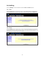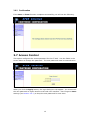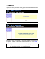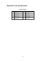
1
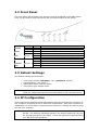
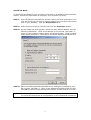
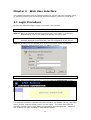
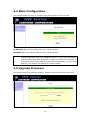
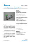
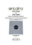
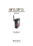
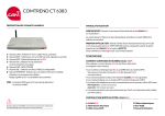
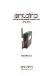
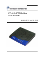
CT-402 GPON Bridge User Manual Version A2.0, July 18, 2008 261069-002 Preface This manual provides information related to the installation, operation, and application of this device. The individual reading this manual is presumed to have a basic understanding of telecommunications terminology and concepts. If you find the product to be inoperable or malfunctioning, please contact technical support for immediate service by email at [email protected] For product update, new product release, manual revision, or software upgrades, please visit our website at http://www.comtrend.com Important Safety Instructions With reference to unpacking, installation, use, and maintenance of your electronic device, the following basic guidelines are recommended: • • • • • • Do not use or install this product near water, to avoid fire or shock hazard. For example, near a bathtub, kitchen sink or laundry tub, or near a swimming pool. Also, do not expose the equipment to rain or damp areas (e.g. a wet basement). Do not connect the power supply cord on elevated surfaces. Allow it to lie freely. There should be no obstructions in its path and no heavy items should be placed on the cord. In addition, do not walk on, step on, or mistreat the cord. Use only the power cord and adapter that are shipped with this device. To safeguard the equipment against overheating, make sure that all openings in the unit that offer exposure to air are not blocked. Avoid using a telephone (other than a cordless type) during an electrical storm. There may be a remote risk of electric shock from lightening. Also, do not use the telephone to report a gas leak in the vicinity of the leak. Never install telephone wiring during stormy weather conditions. CAUTION: • To reduce the risk of fire, use No. 26 AWG or larger telecommunication line cord. • Always disconnect all telephone lines from the wall outlet before servicing or disassembling this equipment. • Although the light intensity of the fiber optic laser is low, there may still be a small risk of damage to your eyes, especially if you wear glasses or contact lenses. To increase your safety, you can take the following precautions: o Before turning on the equipment and connecting to the GPON port, check that the fiber optic cable is not visibly damaged. o Never look straight into the cable or GPON port under any circumstances, even if no light is visible, since laser light is invisible to the human eye! WARNING Disconnect the power line from the device before servicing. Power supply specifications are clearly stated in Appendix B. Copyright Copyright©2008 Comtrend Corporation. All rights reserved. The information contained herein is proprietary to Comtrend Corporation. No part of this document may be translated, transcribed, reproduced, in any form, or by any means without prior written consent of Comtrend Corporation. 1 Protect Our Environment This symbol indicates that when the equipment has reached the end of its useful life, it must be taken to a recycling centre and processed separate from domestic waste. The cardboard box, the plastic contained in the packaging, and the parts that make up this device can be recycled in accordance with regionally established regulations. Never dispose of this electronic equipment along with your household waste. You may be subject to penalties or sanctions under the law. Instead, ask for disposal instructions from your municipal government. NOTE: This document is subject to change without notice. 2 Table of Contents TABLE OF CONTENTS .......................................................................................................................3 CHAPTER 1 SUMMARY .....................................................................................................................4 CHAPTER 2 INSTALLATION.............................................................................................................5 2.1 REAR PANEL ....................................................................................................................................5 2.2 FRONT PANEL ..................................................................................................................................6 2.3 DEFAULT SETTINGS ......................................................................................................................... 6 2.4 IP CONFIGURATION .......................................................................................................................... 6 CHAPTER 3 WEB USER INTERFACE .........................................................................................8 3.1 LOGIN PROCEDURE.......................................................................................................................... 8 3.2 DEVICE INFO ...................................................................................................................................9 3.3 LAN INFO .......................................................................................................................................9 3.4 BASIC CONFIGURATION .................................................................................................................10 3.5 UPGRADE FIRMWARE.....................................................................................................................10 3.6 SETTING ........................................................................................................................................12 3.6.1 Save.................................................................................................................................12 3.6.2 Erase...............................................................................................................................12 3.6.2 Confirmation................................................................................................................... 13 3.7 ACCESS CONTROL ......................................................................................................................... 13 3.8 REBOOT .........................................................................................................................................14 APPENDIX A: PIN ASSIGNMENTS.................................................................................................15 APPENDIX B: SPECIFICATIONS ....................................................................................................16 3 Chapter 1 Summary Comtrend’s CT-402 GPON (Gigabit-capable Passive Optical Network) provides a high-speed data access corridor for customers to easily connect any media device, achieving a Triple-play platform at home. The CT-402 not only conforms to the ITU-T G.984 standard, but also embeds one 10/100/1000M Ethernet LAN port. The CT-402 is easily controlled by a remote system that is flexible enough to interoperate with the OLT units of different venders. It also supports DBA(Dynamic Bandwidth Allocation)algorithm and QoS. FEATURES • • • • • • ITU-T G.984 standard compliance 2.5Gbps downstream / 1.25Gbps upstream Class B+ compliant APD receiver and DFB transmitter IGMP v1/v2/v3 snooping support for IPTV service Traffic QoS support DBA reporting APPLICATION The following diagram depicts a typical application of the CT-402 device. 4 Chapter 2 Installation 2.1 Rear Panel This diagram shows the rear panel of the CT-402. Reset button GPON PORT The installation steps for each rear panel interface is provided below. Power Jack/Button Press the power button to the OFF position (OUT). Connect the power adapter to the power jack. Attach the power adapter to a wall outlet or other AC source. Press the power button to the ON position (IN). Caution 1: Caution 2: If the device fails to power up, or it malfunctions, first verify that the power cords are connected securely. Then power it on again. If the problem persists, contact technical support. Before servicing or disassembling this equipment, always disconnect all power cords and telephone lines from their outlets. Reset Button Restore the default settings of the device by holding down the Reset button for more than five seconds. This may be required if the CT-402 fails to respond normally or if you are locked out of the unit due to configuration changes. GIGABIT LAN Use a 1000BASE-T compliant RJ-45 cable to connect to a Gigabit LAN. This port can also be used to connect to slower 10/100BASE-T networks. The port is auto-sensing MDI/X and either straight-through or crossover cable can be used. GPON PORT Connect a single mode optical fiber to the ITU-T G.984 standard SC/APC connector. NOTE: Avoid looking into the port, as there is some safety risk due to laser light. 5 2.2 Front Panel The front panel LED indicators are shown here and explained in the table below. They can be used to check the power and connection status of the device. LED POWER Color Green GPON ACK Green Red Green LAN Green GIGABIT LAN Green Mode ON OFF ON ON Blink OFF ON OFF ON OFF Function Power is supplied Power is not supplied GPON link is established GPON link is not established Ethernet data transmitting or receiving No data transmitting or receiving Fast Ethernet LAN Link is established Fast Ethernet LAN Link is not established Gigabit Ethernet LAN Link is established Gigabit Ethernet LAN Link is not established 2.3 Default Settings The default settings are as follows: • • • • NOTE: Local (LAN) access (username: root , password: 12345) LAN IP address: 192.168.1.1 LAN subnet mask: 255.255.255.0 Connection type: Bridge mode At power on, the device initializes all settings to default values. It then reads the configuration profile from flash memory and overwrites them. 2.4 IP Configuration These instructions describe the IP configuration steps for the Ethernet connection of any computer connected to the CT-402 local area network. Once this connection is established you will be able to access product features or manage the device using the web user interface. NOTE: These instructions are written for a computer running Microsoft Windows XP SP2. For different operating systems, the specific steps may vary but the general procedure is the same. Check the instructions provided with your OS for further guidance. 6 STATIC IP Mode To access CT-402 features your computer must have an IP address within the same subnet. Follow the steps below to configure your computer correctly. STEP 1: From the Network Connections window, open Local Area Connection (You may also access this screen by double-clicking the Local Area Connection icon on your taskbar). Click the Properties button. STEP 2: Select Internet Protocol (TCP/IP) and click the Properties button. STEP 3: On the dialog box that appears, select the radio button labeled “Use the following IP address”. Enter an IP address in this format {192.168.1.x, where x is any number greater than 2 and less than 254}. Enter a subnet mask of 255.255.255.0. The settings should be displayed as shown here. STEP 3: Enter the default gateway and DNS server settings as provided by your ISP or enter 192.168.1.1, which is the default IP address of the CT-402. Click OK to submit these settings and thereby activate STATIC IP mode. NOTE: If you change the IP address of the CT-402 using the web user interface, you must also change the IP configuration of your networked computers. 7 Chapter 3 Web User Interface This chapter describes how to manage the device via the web user interface using an Internet browser such as Microsoft Internet Explorer (version 5.0 and later). 3.1 Login Procedure Perform the following steps to login to the web user interface. NOTE: The default settings can be found in 2.3 Default Settings. STEP 1: Start the Internet browser and enter http://192.168.1.1 in the web address field. This is the default IP address for the CT-402. NOTE: For local administration (i.e. LAN access), the PC running the browser must be attached to the Ethernet, and not necessarily to the device. STEP 2: A dialog box will appear, such as the one below. Enter the default username and password and click OK to continue. NOTE: The login password can be changed later (see section 3.7 Access Control) STEP 3: After successfully logging in, you will reach the Device Info screen. The web user interface is divided into three sections, the header (at top), the main menu (at left), and the display screen (on the right). The main menu has the following options: Device Info, Basic Configuration, and Management. Selecting one of these will open a submenu with related options. 8 3.2 Device Info The Device Info summary screen, shown below, is the default startup screen and the first selection on the main menu. It shows the CT-402 software version. NOTE: The software version can be changed (see section 3.5 Upgrade Firmware) 3.3 LAN Info Click Device Info on the main menu and select LAN Info from the Device Info submenu to display the LAN IP address and subnet mask of the CT-402. NOTE: These values can be changed (see section 3.4 Basic Configuration) 9 3.4 Basic Configuration This screen allows the user to configure the LAN interface on the CT-402. IP Address: Enter the IP address for the CT-402 LAN port. NetMask: Enter the subnet mask for the CT-402 LAN port. NOTE: Click the Apply button to immediately change the IP settings. These new settings will remain until you reboot the device. If you wish to keep the new IP configuration after power off or reboot, you must save settings. If you wish to return to the default configuration immediately, you can erase settings. See section 3.6 Setting for further details. 3.5 Upgrade Firmware This screen allows for software updates. Detailed instructions follow this figure. 10 Step 1: Obtain an updated software image file from your ISP. Step 2: Enter the path and filename of the firmware image file in the Software File Name field or click the Browse button to locate the image file. Firmware image files normally end with the “.bin” extension. Step 3: Click the Upgrade button once to upload and install the file. The update process will take about a minute to complete. After a successful upgrade, you will see the following screen and the device will reboot. NOTE1: The browser window will normally refresh to the default screen. If it does not, close all browser windows and then restart the browser. If you continue to experience problems, clearing the browser cache may help. NOTE2: It is recommended that you compare the Software Version shown on the Device Info screen (see section 3.2 Device Info) with the firmware version just installed, to confirm that the installation was successful. 11 3.6 Setting Click on Setting to reveal a submenu with the Save and Erase options. 3.6.1 Save Click the Save button to keep the current CT-402 LAN IP address and password. These settings will be burned to flash memory and will remain until you Erase them. 3.6.2 Erase Click the Erase button to discard the current CT-402 LAN IP address and password. These settings will be erased from flash memory and reset to default settings. You must reboot the CT-402 to effect this change. 12 3.6.2 Confirmation If the Save or Erase function completes successfully you will see the following. 3.7 Access Control This option configures the access password for the CT-402. Use the fields in the screen below to change the password. The new password must be entered twice. When you click the Apply button, the login dialog box will appear. You must enter the new password to regain access to the web user interface. Don’t forget to Save settings (see section 3.6.1) to keep the new password for next time. 13 3.8 Reboot This function reboots the CT-402. You will lose any changes to LAN IP configuration or passwords unless you first Save settings (see section 3.6.1 Save). When you click the Reboot button, the following screen will appear. If necessary, you can reconfigure the IP configuration while the device is rebooting. For example, the Static IP settings may need to be adjusted (see section 2.4 IP Configuration for detailed instructions). NOTE: If you lose all access to the web user interface (WUI), you may need to close the browser, wait for two minutes, and then restart it. If this does not work, then press the reset button on the rear panel of the device for 5-7 seconds to restore the device to default settings. 14 Appendix A: Pin Assignments LAN Port (RJ45) Pin 1 2 3 4 Definition Transmit/Receive Data Pair 1+ Transmit/Receive Data Pair 1Transmit/Receive Data Pair 2+ Transmit/Receive Data Pair 3+ Pin 5 6 7 8 15 Definition Transmit/Receive Data Pair 3Transmit/Receive Data Pair 2Transmit/Receive Data Pair 4+ Transmit/Receive Data Pair 4- Appendix B: Specifications Rear Panel 1 X GPON Port, 1 X ETHERNET 10/100/1000Base-T port (MDI/MDIX), 1 X Power Jack, 1 X Power button, 1 X Reset Button GPON Standard...........................ITU-T G.984 Optical Line Rate ................Downstream: 2.488Gbps / Upstream: 1.244Gbps Connector .........................SC/APC Optical Fiber ......................Single mode Wavelength .......................1490nm (downstream) / 1310nm (upstream) Optical Budget ...................Class B+ (13 – 28 dB) Transmission Distance.........Min. 20 km within class B+ Splitting ratio.....................1 by 64 within class B+ Ethernet Standard ..........................IEEE 802.3, IEEE 802.3u 10/100/1000 BaseT ............Auto-sense MDI/MDX support...............Yes Management Web-based management with software upgrade function Bridge Functions Transparent bridging and learning ............IEEE 802.1d Spanning Tree Algorithm .........................Yes IGMP Proxy ...........................................Yes Power Supply External power adapter ...........................Input: 110 / 220 Vac Output: 15 V, 1 A Environment Condition Operating temperature ...........................0 ~ 50 degrees Celsius Relative humidity ...................................5 ~ 90% (non-condensing) Dimensions ...........205 mm (W) x 47 mm (H) x 145 mm (D) Certifications.........CE NOTE: Specifications are subject to change without notice. 16