1
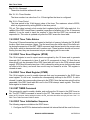
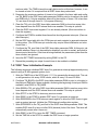
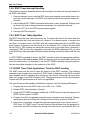
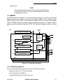
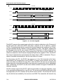
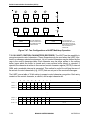
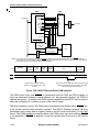
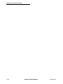
IDMA Channels
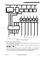
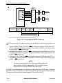
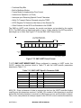
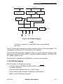
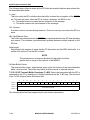
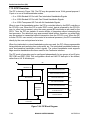
IDMA BD BASE
ADDRESS (IBASE)
BD 0
SOURCE DEVICE OR
DATA BUFFER 0
DESTINATION DEVICE
OR DATA BUFFER 0
BD 1
BD 2
SOURCE DEVICE OR
DATA BUFFER 1
DESTINATION DEVICE
OR DATA BUFFER 1
SOURCE DEVICE OR
DATA BUFFER 2
DESTINATION DEVICE
OR DATA BUFFER 2
BD N
DESTINATION DEVICE
OR DATA BUFFER N
SOURCE DEVICE OR
DATA BUFFER N
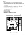
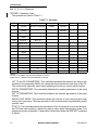
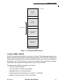
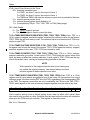
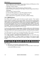
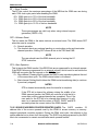
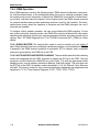
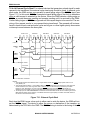
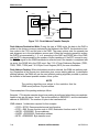
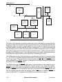
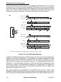
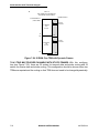
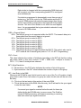
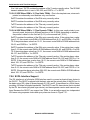
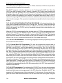
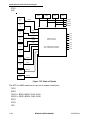
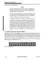
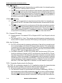
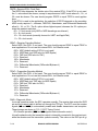
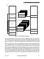
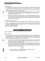
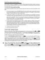
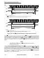
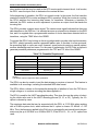
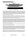
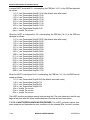
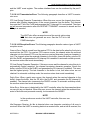
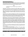
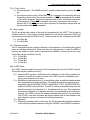
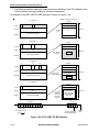
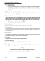
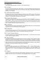
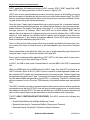
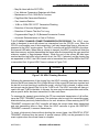
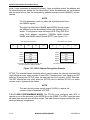
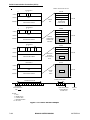
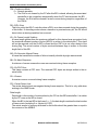
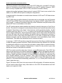
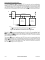
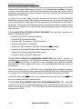
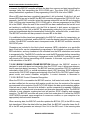
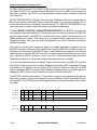
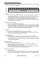
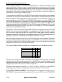
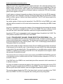
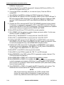
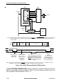
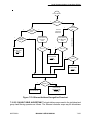
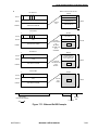
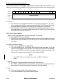
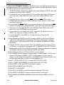
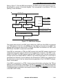
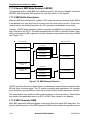
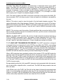
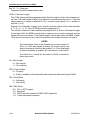
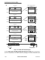
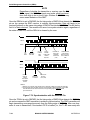
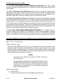
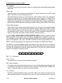
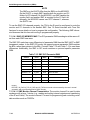
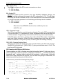
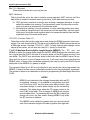
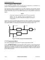
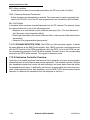
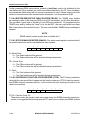
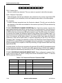
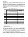
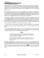
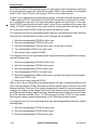
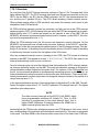
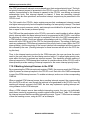
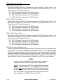
Figure 7-9. IDMA BD Ring
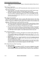
The data associated with each IDMA channel for the auto buffer and buffer chaining modes
is stored in buffers. Each buffer is referenced by a BD. The BDs use a ring structure located
in the dual-port RAM.
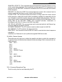
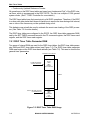
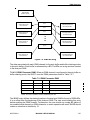
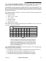
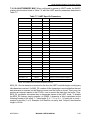
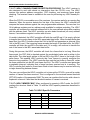
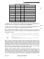
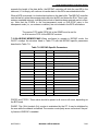
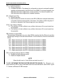
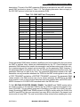
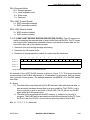
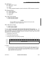
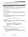
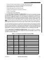
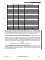
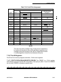
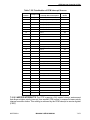
7.6.4.2.1 IDMA Parameter RAM. When an IDMA channel is configured to the auto buffer or
buffer chaining mode, the QUICC uses the IDMA parameters listed in Table 7-2.T
Table 7-3. IDMA Parameter RAM
Address
Name
Width
Description
IDMA Base + 00
IBASE
Word
IDMA BD Base Address
IDMA Base + 02
IBPTR
Word
IDMA BD Pointer
IDMA Base + 04
ISTATE
Long
IDMA Internal State
IDMA Base + 08
ITEMP
Long
IDMA Temp
NOTE: The entry in boldface must be initialized by the user.
The IBASE entry defines the starting location in the dual-port RAM for the set of IDMA BDs.
It is an offset from the beginning of the dual-port RAM. The user must initialize this entry
before enabling the IDMA channel. Furthermore, the user should not overlap BD tables of
two enabled serial channels or IDMA channels, or erratic operation will result. IBASE should
contain a value that is divisible by 16.
MOTOROLA
MC68360 USER’S MANUAL
7-35