1
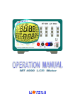
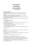
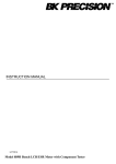
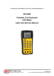
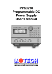
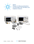
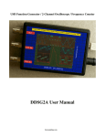
MT 4080 LCR METER OPERATING MANUAL Contents 1. INTRODUCTION ................................................................1 GENERAL .............................................................................1 IMPEDANCE PARAMETERS ..................................................3 SPECIFICATION ....................................................................6 ACCESSORIES ....................................................................19 2. OPERATION ......................................................................20 2.1 PHYSICAL DESCRIPTION ...................................................20 2.2 MAKING MEASUREMENT ..................................................21 3. 1.1 1.2 1.3 1.4 2.2.1 Battery Replacement .....................................................................21 2.2.2 Battery Recharging/AC operation ..............................................22 2.2.3 Open and Short Calibration ........................................................23 2.2.4 Display Speed ................................................................................24 2.2.5 Relative Mode ................................................................................24 2.2.6 Range Hold.....................................................................................24 2.2.7 DC Resistance Measurement.......................................................25 2.2.8 AC Impedance Measurement.......................................................25 2.2.9 Capacitance Measurement ..........................................................25 2.2.10 Inductance Measurement .............................................................26 2.3 ACCESSORY OPERATION ...................................................27 USB OPERATION .............................................................29 3.1 COMMAND SYNTAX ..........................................................30 3.2 COMMANDS .......................................................................31 4. APPLICATION ..................................................................39 4.1 TEST LEADS C ONNECTION ...............................................39 4.2 OPEN/SHORT C OMPENSATION ..........................................44 4.3 SELECTING THE SERIES OR PARALLEL MODE ..................46 5. WARRANTY INFORMATION .......................................49 6. SAFETY PRECAUTION ..................................................51 1. Introduction 1.1 General The MT4080 is a high accuracy handheld LCR meter that can perform the inductor, capacitor and resistor measurement up to 100KHz within 0.2% basic accuracy. It is the most advanced handheld AC/DC impedance measurement instrument to date. The MT4080 can help engineers and students to understand the characteristic of electronics components. It is also of great assistance to those people who want to do the quality control of the electronics components. The instrument is auto or manual ranging. Test frequencies of 100Hz, 120Hz, 1KHz, 10KHz or 100KHz (MT4080A only) may be selected on all applicable ranges. The test voltages of 50mVrms, 0.25Vrms, 1Vrms or 1VDC (DCR only) may also be selected on all applicable ranges. The dual display feature permits simultaneous measurements. Components can be measured in the series or parallel mode as desired; the more standard method is automatically selected first but can be overridden. The highly versatile MT4080 can perform virtually all the functions of most bench type LCR bridges. With a basic accuracy of 0.2%, this economical LCR meter may be adequately substituted for a more expensive LCR bridge in many situations. The meter is powered from two AA Batteries and is supplied with an AC to DC charging adapter and two AA Ni-Mh Rechargeable 1 Batteries. The instrument has applications in electronic engineering labs, production facilities, service shops, and schools. It can be used to check ESR values of capacitors, sort values, select precision values, measure unmarked and unknown inductors, capacitors or resistors, and to measure capacitance, inductance, or resistance of cables, switches, circuit board foils, etc. The key features are as following: Test condition: 1 Frequency : 100Hz / 120Hz / 1KHz / 10KHz / 100KHz (MT4080A only) 2. Level : 1Vrms / 0.25Vrms / 50mVrms / 1VDC (DCR only) Measurement Parameters : Z, Ls, Lp, Cs, Cp, DCR, ESR, D, Q and θ Basic Accuracy: 0.2% Dual Liquid Crystal Display Fast/Slow Measurement Auto Range or Range Hold USB Interface Communication Open/Short Calibration Primary Parameters Display: Z : AC Impedance DCR : DC Resistance Ls : Serial Inductance Lp : Parallel Inductance Cs : Serial Capacitance Cp : Parallel Capacitance 2 Second Parameter Display: θ : Phase Angle ESR : Equivalence Serial Resistance D : Dissipation Factor Q : Quality Factor Combinations of Display: Serial Mode : Z –θ, Cs – D, Cs – Q, Cs – ESR, Ls – D, Ls – Q, Ls – ESR Parallel Mode : Cp – D, Cp – Q, Lp – D, Lp – Q 1.2 Impedance Parameters Due to the different testing signals on the impedance measurement instrument, there are DC impedance and AC impedance. The common digital multi-meter can only measure the DC impedance, but the MT4080 can do both. It is a very important issue to understand the impedance parameters of the electronic component. When we analysis the impedance by the impedance measurement plane (Figure 1.1). It can be visualized by the real element on the X-axis and the imaginary element on the y-axis. This impedance measurement plane can also be seen as the polar coordinates. The Z is the magnitude and the θ is the phase of the impedance. 3 Imaginary Axis X Z (R s , X s ) s Z θ Rs Z = R s + jX Real Axis Figure 1.1 s = Z ∠ θ (Ω ) R s = Z Cos θ Z = X s = Z Sin θ Rs + X s 2 θ = Tan Z = (Impedance R S = (Resistance X S = (Reactance Ω = (Ohm ) −1 2 Xs Rs ) ) ) There are two different types of reactance: Inductive (XL) and Capacitive (XC). It can be defined as follows: X L = ωL = 2πfL L = Inductan ce( H ) 1 1 = XC = ωC 2πfC C = Capacitan ce(F ) f = Frequency(Hz) Also, there are quality factor (Q) and the dissipation factor (D) that need to be discussed. For component, the quality factor serves as a measure of the reactance purity. In the real world, there is always 4 some associated resistance that dissipates power, decreasing the amount of energy that can be recovered. The quality factor can be defined as the ratio of the stored energy (reactance) and the dissipated energy (resistance). Q is generally used for inductors and D for capacitors. 1 1 = D tan δ Xs ωL s 1 = = = Rs Rs ωC s R s B = G Rp Rp = = = ωC p R p X p ωL p Q= There are two types of the circuit mode. One is series mode, the other is parallel mode. See Figure 1.2 to find out the relation of the series and parallel mode. 5 Real and imaginary components are serial Rs jXs Z = Rs + jX s Real and imaginary components are Parallel Rp jXp Y= G=1/Rp jB=1/jXp 1 1 + RP jX P Y = G + jB Figure 1.2 1.3 Specification LCD Display Range: Parameter Z L C DCR ESR D Q θ Display Range 0.000 Ω to 9999 MΩ 0.000 µH to 9999 H 0.000 pF to 9999 F 0.000 Ω to 9999 MΩ 0.000 Ω to 9999 Ω 0.000 to 9999 0.000 to 9999 -180.0 ° to 180.0 ° 6 Accuracy (Ae): Z Accuracy: |Zx| 20M ~ 10M Freq. (Ω) DCR 2% 1 100Hz 120Hz 1KHz 10KHz 5% 1 100KHz NA (4080A) 10M ~ 1M ~ 100K ~ 10 ~ 1 1 ~ 0.1 1M 100K 10 (Ω) (Ω) (Ω) (Ω) (Ω) 1% 1 0.5% 0.2% 0.5% 1% 1 1 1 1 2% 1 5%1 2%1 0.4% 2%1 1 5%1 Note : 1.The accuracy applies when the test level is set to 1Vrms. 2.Ae multiplies 1.25 when the test level is set to 250mVrms. 3.Ae multiplies 1.50 when the test level is set to 50mVrms. 4.When measuring L and C, multiply Ae by 1+ Dx 2 if the Dx0.1. : Ae is not specified if the test level is set to 50mV. 7 C Accuracy : 100Hz 120Hz 1KHz 10KHz 79.57 pF 159.1 pF 2% ± 1 66.31 pF 132.6 pF 2% ± 1 7.957 pF 15.91 pF 2% ± 1 0.795 pF 1.591 pF 5% ± 1 NA 100KHz (4080A) NA 159.1 pF 1.591 nF 1% ± 1 132.6 pF 1.326 nF 1% ± 1 15.91 pF 159.1 pF 1% ± 1 1.591 pF 15.91 pF 2% ± 1 0.159 pF 1.591 pF 5% ± 1 1.591 nF 15.91 nF 0.5% ±1 1.326 nF 13.26 nF 0.5% ±1 159.1 pF 1.591 nF 0.5% ±1 15.91 pF 159.1 pF 0.5% ±1 1.591 pF 15.91 pF 2%± 1 8 15.91 nF 159.1 uF 0.2% ±1 13.26 nF 132.6 uF 0.2% ±1 1.591 nF 15.91 uF 0.2% ±1 159.1 pF 1.591 uF 0.2% ±1 15.91 pF 159.1 nF 0.4% ±1 159.1 uF 1591 uF 0.5% ±1 132.6 uF 1326 uF 0.5% ±1 15.91 uF 159.1 uF 0.5% ±1 1.591 uF 15.91 uF 0.5% ±1 159.1 nF 1.591 uF 2%± 1 1591 uF 15.91 mF 1% ± 1 1326 uF 13.26 mF 1% ± 1 159.1 uF 1.591 mF 1% ± 1 15.91 uF 159.1 uF 1% ± 1 1.591 uF 15.91 uF 5% ± 1 L Accuracy : 100Hz 120Hz 1KHz 10KHz 100KHz (4080A) 31.83 KH 15.91 KH 2% ± 1 26.52 KH 13.26 KH 2% ± 1 3.183 KH 1.591 KH 2% ± 1 318.3 H 159.1 H 5% ± 1 31.83 H 15.91 H NA 15.91 KH 1591 H 1% ± 1 13.26 KH 1326 H 1% ± 1 1.591 KH 159.1 H 1% ± 1 159.1 H 15.91 H 2% ± 1 15.91 H 1.591 H 5% ± 1 1591 H 159.1 H 0.5% ±1 1326 H 132.6 H 0.5% ±1 159.1 H 15.91 H 0.5% ±1 15.91 H 1.591 H 0.5% ±1 1.591 H 159.1 mH 2%± 1 9 159.1 H 15.91 mH 0.2% ±1 132.6 H 13.26 mH 0.2% ±1 15.91 H 1.591 mH 0.2% ±1 1.591 H 159.1 uH 0.2% ±1 159.1 mH 15.91 uH 0.4% ±1 15.91 mH 1.591 mH 0.5% ±1 13.26 mH 1.326 mH 0.5% ±1 1.591 mH 159.1 uH 0.5% ±1 159.1 uH 15.91 uH 0.5% ±1 15.91 uH 1.591 uH 2%± 1 1.591 mH 159.1 uH 1% ± 1 1.326 mH 132.6 uH 1% ± 1 159.1 uH 15.91 uH 1% ± 1 15.91 uH 1.591 uH 1% ± 1 1.591 uH 0.159 uH 5% ± 1 D Accuracy : |Zx| Freq. 100Hz 120Hz 20M ~ 10M (Ω) 0.020 10M ~ 1M (Ω) 0.010 1M ~ 100K (Ω) 0.005 100K ~ 10 (Ω) 0.002 10 ~ 1 1 ~ 0.1 (Ω) 0.005 (Ω) 0.010 0.050 NA 0.020 0.050 0.020 0.004 0.020 0.050 20M ~ 10M (Ω) 1.046 10M ~ 1M (Ω) 0.523 1M ~ 100K (Ω) 0.261 100K ~ 10 (Ω) 0.105 10 ~ 1 1 ~ 0.1 (Ω) 0.261 (Ω) 0.523 2.615 NA 1.046 1.046 0.209 1.046 2.615 1KHz 10KHz 100KHz (4080A) θ Accuracy : |Zx| Freq. 100Hz 120Hz 1KHz 10KHz 100KHz (4080A) 2.615 10 Z Accuracy: As shown in table 1. C Accuracy: Zx = 1 2 ⋅ π ⋅ f ⋅ Cx C Ae = Ae of |Zx| f : Test Frequency (Hz) Cx : Measured Capacitance Value (F) |Zx| : Measured Impedance Value (Ω) Accuracy applies when Dx (measured D value) 0.1 When Dx > 0.1, multiply C Ae by 1 + Dx 2 Example: Test Condition: Frequency : 1KHz Level : 1Vrms Speed : Slow DUT : 100nF Then 1 Zx = 2 ⋅ π ⋅ f ⋅ Cx 1 = = 1590Ω 2 ⋅ π ⋅103 ⋅100 ⋅ 10− 9 Refer to the accuracy table, get C Ae=±0.2% 11 L Accuracy: Zx = 2 ⋅ π ⋅ f ⋅ Lx LAe = Ae of |Zx| f : Test Frequency (Hz) Lx : Measured Inductance Value (H) |Zx| : Measured Impedance Value (Ω) Accuracy applies when Dx (measured D value) 0.1 When Dx > 0.1, multiply LAe by 1 + Dx 2 Example: Test Condition: Frequency : 1KHz Level : 1Vrms Speed : Slow DUT : 1mH Then Zx = 2 ⋅ π ⋅ f ⋅ Lx = 2 ⋅ π ⋅103 ⋅10 − 3 = 6.283Ω Refer to the accuracy table, get LAe=±0.5% ESR Accuracy: ESRAe = ± Xx ⋅ Ae 100 Xx = 2 ⋅ π ⋅ f ⋅ Lx = 1 2 ⋅ π ⋅ f ⋅ Cx 12 ESR Ae = Ae of |Zx| f : Test Frequency (Hz) Xx : Measured Reactance Value (Ω) Lx : Measured Inductance Value (H) Cx : Measured Capacitance Value (F) Accuracy applies when Dx (measured D value) 0.1 Example: Test Condition: Frequency : 1KHz Level : 1Vrms Speed : Slow DUT : 100nF Then 1 Zx = 2 ⋅ π ⋅ f ⋅ Cx 1 = = 1590Ω 3 2 ⋅ π ⋅10 ⋅100 ⋅10 − 9 Refer to the accuracy table, get C Ae=±0.2%, Ae ESRAe = ± Xx ⋅ = ±3.18Ω 100 D Accuracy: D Ae = ± Ae 100 13 DAe = Ae of |Zx| Accuracy applies when Dx (measured D value) 0.1 When Dx > 0.1, multiply Dx by (1+Dx) Example: Test Condition: Frequency : 1KHz Level : 1Vrms Speed : Slow DUT : 100nF Then 1 Zx = 2 ⋅ π ⋅ f ⋅ Cx 1 = = 1590Ω 3 2 ⋅ π ⋅10 ⋅100 ⋅ 10− 9 Refer to the accuracy table, get C Ae=±0.2%, Ae D Ae = ± ⋅ = ±0.002 100 Q Accuracy: Q Ae =± 2 Qx ⋅ De 1 m Qx ⋅ De QAe = Ae of |Zx| Qx : Measured Quality Factor Value De : Relative D Accuracy 14 Accuracy applies when Qx ⋅ De < 1 Example: Test Condition: Frequency : 1KHz Level : 1Vrms Speed : Slow DUT : 1mH Then Zx = 2 ⋅ π ⋅ f ⋅ Lx = 2 ⋅ π ⋅103 ⋅10 − 3 = 6.283Ω Refer to the accuracy table, get LAe=±0.5%, Ae De = ± ⋅ = ±0.005 100 If measured Qx = 20 Then Qx 2 ⋅ De Q Ae = ± 1 m Qx ⋅ De 2 =± 1 m 0.1 θ Accuracy: θe = 180 Ae ⋅ π 100 15 Example: Test Condition: Frequency : 1KHz Level : 1Vrms Speed : Slow DUT : 100nF Then 1 Zx = 2 ⋅ π ⋅ f ⋅ Cx 1 = = 1590Ω 3 2 ⋅ π ⋅10 ⋅100 ⋅ 10− 9 Refer to the accuracy table, get ZAe=±0.2%, 180 Ae θ Ae = ± ⋅ π 100 180 0.2 =± ⋅ = ±0.115 deg π 100 Testing Signal: Level Accuracy Frequency Accuracy : ± 5% : 0.1% Output Impedance : 100Ω ± 5% Measuring Speed: Fast : 4.5 meas. / sec. Slow : 2.5 meas. / sec. 16 General: Temperature Relative Humidity Battery Type Battery Charge : 0°C to 40°C (Operating) -20°C to 70°C (Storage) Up to 85% 2 AA size Ni-Mh or Alkaline Constant current 150mA approximately 2.5 Hours typical 110/220V AC, 60/50Hz with proper adapter under 2.2V 174mm x 86mm x 48mm (L x W x H) 6.9” x 3.4” x 1.9” 470g : : : Battery Operating Time : AC Operation : Low Power Warning Dimensions : : Weight : Considerations Test Frequency. The test frequency is user selectable and can be changed. Generally, a 1kHz test signal is used to measure capacitors that are 0.01uF or smaller and a 120Hz test signal is used for capacitors that are 10uF or larger. Typically a 1 kHz test signal is used to measure inductors that are used in audio and RF (radio frequency) circuits. This is because these components operate at higher frequencies and require that they be measured at a higher frequency of 1kHz. Generally, inductors below 2mH should be measured at 1 kHz and inductors above 200H should be measured at 120Hz. It is best to check with the component manufacturer’s data sheet to determine the best test frequency for the device. 17 Charged Capacitors Always discharge any capacitor prior to making a measurement since a charged capacitor may seriously damage the meter. Effect Of High D on Accuracy A low D (Dissipation Factor) reading is desirable. Electrolytic capacitors inherently have a higher dissipation factor due to their normally high internal leakage characteristics. If the D (Dissipation Factor) is excessive, the capacitance measurement accuracy may be degraded. It is best to check with the component manufacturers’ data sheet to determine the desirable D value of a good component. Combining Auto ranging and Manual Ranging Operation Combining auto ranging and manual ranging is a very convenient way to gain the advantage of both modes. Starting in the auto ranging mode, insert or connect the inductor to be measured, The instrument quickly steps to the correct range for measurement. Next, press the RANGE key to switch to the manual ranging mode. The instrument will be on the correct range. The display will indicate whether a calibration needs to be performed to obtain optimum accuracy. If not, take the reading. If so, perform the calibration then take the reading, This method combines the speed of auto ranging and the accuracy of manual ranging and is very easy and simple to perform. Series Vs Parallel Measurement (for Inductors) 18 The MT4080 normally measures inductance in the series equivalent mode. The series mode displays the more accurate measurement in most cases. The series equivalent mode is essential for obtaining an accurate Q reading of low Q inductors. Where ohmic losses are most significant, the series equivalent mode is preferred. However, there are cases where the parallel equivalent mode may be more appropriate. For iron core inductors operating at higher frequencies where hysteresis and eddy currents become significant, measurement in the parallel equivalent mode is preferred. 1.4 Accessories Operating Manual 2 AA Size Ni-Mh Rechargeable Batteries Shorting Bar AC to DC Adapter TL08A SMD Test Probe (Optional) TL08B 4-Wire Test Clip (Optional) TL08C Kelvin Clip (Optional) Carrying Case (Optional) 19 1 pc 2 pcs 1 pc 1 pc 2. Operation 2.1 Physical Description 1. 3. 5. 7. 9. 11. 13. 15. 17. 19. H POT L POT G UARD H CUR L CUR G UARD USB Port Secondary Parameter Display Model Number Relative Key Open/Short Calibration Key Display Update Speed Key Range Hold Key Battery Charge Indicator Guard Terminal LPOT/LCUR Terminal 2. 4. 6. 8. 10. 12. 14. 16. 18. 20. 2 0 Primary Parameter Display Low Battery Indicator Power Switch Measurement Level Key Measurement Frequency Key D/Q/ /ESR Function Key L/C/Z/DCR Function Key DC Adapter Input Jack HPOT/HCUR Terminal Battery Compartment 2.2 Making Measurement 2.2.1 Battery Replacement When the LOW BATTERY INDICATOR lights up during normal operation, the batteries in the MT4080 should be replaced or recharged to maintain proper operation. Please perform the following steps to change the batteries: 1. Remove the battery hatch by unscrewing the screw of the battery compartment. 2. Take out the old batteries and insert the new batteries into the battery compartment. Please watch out for battery polarity when installing new batteries. 3. Replace the battery hatch by reversing the procedure used to remove it. 1 2 3 4 5 6 Screws Battery Compartment Hatch Batteries Norm/Ni-Mh Switch Back Case Tilt Stand Battery Replacement 2 1 2.2.2 Battery Recharging/AC operation Caution ! Only the MT4080 standard accessory AC to DC adapter can be used with MT4080. Other battery eliminator or charger may result in damage to MT4080. The MT4080 works on external AC power or internal batteries. To power the MT4080 with AC source, make sure that the MT4080 is off, then plug one end of the AC to DC adapter into the DC jack on the right side of the instrument and the other end into an AC outlet. There is a small slide switch inside the battery compartment called Battery Select Switch. If the Ni-Mh or Ni-Cd rechargeable batteries are installed in MT4080, set the Battery Select Switch to "Ni-Mh" position. The Ni-Mh or Ni-Cd batteries can be recharged when the instrument is operated by AC source. The LED for indicating battery charging will light on. If the non-rechargeable batteries (such as alkaline batteries) are installed in MT4080, set the Battery Select Switch to "NORM" position for disconnecting the charging circuit to the batteries. Warning The Battery Select Switch must be set in the "NORM" position when using non-rechargeable batteries. Non-rechargeable batteries may explode if the AC adapter is used with non-rechargeable batteries. Warranty is voided if this happened. 2 2 2.2.3 Open and Short Calibration The MT4080 provides open/short calibration capability so the user can get better accuracy in measuring high and low impedance. We recommend that the user performs open/short calibration if the test level or frequency has been changed. Open Calibration First, remaining the measurement terminals with the open status, then, press the CAL key shortly (no more than two second), the LCD will display: This calibration takes about 10 seconds. After it is finished, the MT4080 will beep to show that the calibration is done. Short Calibration To perform the short calibration, insert the Shorting Bar into the measurement terminals. Press the CAL key for more than two second, the LCD will display: This calibration takes about 10 seconds. After it is finished, the MT4080 will beep to show that the calibration is done. 2 3 2.2.4 Display Speed The MT4080 provide two different display speeds (Fast/Slow). It is controlled by the Speed key. When the speed is set to fast, the display will update 4.5 readings every second. When the speed is set to slow, it’s only 2.5 readings per second. 2.2.5 Relative Mode The relative mode lets the user to make quick sort of a bunch of components. First, insert the standard value component to get the standard value reading. (Approximately 5 seconds in Fast Mode to get a stable reading.) Then, press the Relative key, the primary display will reset to zero. Remove the standard value component and insert the unknown component, the LCD will show the value that is the difference between the standard value and unknown value. 2.2.6 Range Hold To set the range hold, insert a standard component in that measurement range. (Approximately 5 seconds in Fast Mode to get a stable reading.) Then, by pressing the Range Hold key it will hold the range within 0.5 to 2 times of the current measurement range. When the Range Hold is press the LCD display: 2 4 2.2.7 DC Resistance Measurement The DC resistance measurement measures the resistance of an unknown component by 1VDC. Select the L/C/Z/DCR key to make the DCR measurement. The LCD display: 2.2.8 AC Impedance Measurement The AC impedance measurement measures the Z of an unknown device. Select the L/C/Z/DCR key to make the Z measurement. The LCD display: The testing level and frequency can by selected by pressing the Level key and Frequency key, respectively. 2.2.9 Capacitance Measurement To measure the capacitance of a component, select the L/C/Z/DCR key to Cs or Cp mode. Due to the circuit structure, there are two modes can by selected (Serial Mode – Cs and Parallel Mode – Cp). If the serial mode (Cs) is selected, the D, Q and ESR can be shown on the secondary display. If the parallel mode (Cp) is selected, only 2 5 the D and Q can be shown on the secondary display. The following shows some examples of capacitance measurement: The testing level and frequency can by selected by pressing the Level key and Frequency key, respectively. 2.2.10 Inductance Measurement Select the L/C/Z/DCR key to Ls or Lp mode for measuring the inductance in serial mode or parallel mode. If the serial mode (Ls) is selected, the D, Q and ESR can be shown on the secondary display. If the parallel mode (Lp) is selected, only the D and Q can be shown on the secondary display. The following shows some examples of capacitance measurement: The testing level and frequency can by selected by pressing the Level key and Frequency key, respectively. 2 6 2.3 Accessory Operation Follow the figures below to attach the test probes for making measurement. Shorting Bar TL08A SMD Test Probe 2 7 HP HC LP LC TL08B 4-Wire Test Clip TL08C Kelvin Clip 2 8 3. USB Operation There are three operation modes in the USB operation of MT4080. They are Normal, Remote and Remote Binning modes. Normal: The Normal mode is the default power on local mode. It is a local mode that the MT4080 is controlled by the keypad and the results of the measurement will be sent to LCD display and a remote USB equipped PC through the build-in USB port. Remote: In the Remote mode, the MT4080 is capable of communicating to USB equipped PC or terminal through the build-in USB interface. The connection setting is as follow: Transmission Mode : Half Duplex Baud Rate : 9600 Parity Bit : None Data Bits :8 Stop Bit :1 Handshake : None In this mode, the keyboard and LCD will be locked. And, the MT4080 measurement is controlled by the external program through the USB port. Remote Binning: In the Remote Binning mode, the “RMT” on the LCD will flash. The MT4080 performs as a TALK ONLY instrument. That means, the measurement of MT4080 is controlled by instrument keys, but the measured value will display on the LCD as well as output to the USB port. By this way, the user can purchase the optional application program provided by Motech to obtain the GO/NO GO comparator and the component sorting comparator. 2 9 3.1 Command Syntax The command syntax of MT4080 is as following: COMMAND(?) (PARAMETER) The format of COMMAND and PARAMETER is as following: 1. There is at least one space between COMMAND and PARAMETER. 2. The PARAMETER should use only ASCII string not numerical code. 3. Value parameter can be integer, floating or exponent with the unit. For example: 50mV 0.05V 5.0e1mV 4. The question mark (?) at the end of COMMAND means a query or measure back command. For example: “CpD” sets the measurement mode to Cp and D. “CpD?” sets the measurement mode to Cp and D as well as measures the values and send it back. 5. The COMMAND and PARAMETER can be either upper or lower case. But the unit to describe the value in the PARAMETER should have different between milli (m) and mega (M). For example: 1mV equals 0.001V. 1MV equals 1000000V. 6. The “end of command” character should placed at the end. There are: ASCII CR (0DH) or ASCII LF (0AH) 3 0 3.2 Commands Measurement Setting (or Querying) Command The following measurement mode-setting and the query commands are supported in the MT4080. When a mode-setting command is entered the MT4080 will return the ASCII CR (0DH) and ASCII LF (0AH) after setting is complete. When query command is entered, the MT4080 will send back the values of measurement. After a command is entered, the meter shall respond within 2.5 seconds with the return values follow the ASCII CR and ASCII LF. If an illegal command is entered, there is no response from the meter. DCR(?) DC resistance measurement mode setting or querying command. CpRp(?) Parallel capacitance and parallel resistance measurement mode setting or querying command. CpQ(?) Parallel capacitance and quality factor measurement mode setting or querying command. CpD(?) Parallel capacitance and dissipation factor measurement mode setting or querying command. CsRs(?) Serial capacitance and serial resistance measurement mode setting or querying command. CsQ(?) Serial capacitance and quality factor measurement mode setting or querying command. CsD(?) Serial capacitance and dissipation factor measurement mode setting or querying command. 3 1 LpRp(?) Parallel inductance and parallel resistance measurement mode setting or querying command. LpQ(?) Parallel inductance and quality factor measurement mode setting or querying command. LpD(?) Parallel inductance and dissipation factor measurement mode setting or querying command. LsRs(?) Serial inductance and serial resistance measurement mode setting or querying command. LsQ(?) Serial inductance and quality factor measurement mode setting or querying command. LsD(?) Serial inductance and dissipation factor measurement mode setting or querying command. RsXs(?) Serial resistance and serial reactance measurement mode setting or querying command. RpXp(?) Parallel resistance and parallel reactance measurement mode setting or querying command. ZTD(?) Impedance and angle (Deg) measurement mode setting or querying command. ZTR(?) Impedance and angle (Rad) measurement mode setting or querying command. Example: CPD (set to Cp-D measurement mode) CPD? 0.22724 0.12840 (return value) DCR? 5.1029 (return value) *IDN? 3 2 Queries and identifies the LCR Meter. This command is used to identify the basic information of LCR Meter. *RST Reset the MT4080 to the power on default status. The default status is: 1KHz 1Vrms SLOW CpD uF mH Ohm After the MT4080 is reset, it will beep once and returns the “BEEP” string back. ASC Set the format of the return value. This command sets the ASCII string return or the numerical code. PARAMETER: ON ASCII string OFF Numerical code Example: ASC ON FREQ? 1KHz (return value) ASC OFF FREQ? 2 (return value) CORR OPEN Perform the open calibration. This command sets the MT4080 to do the open calibration. After the calibration is done, the MT4080 will beep once and returns the “BEEP” string back. CORR SHORT 3 3 Perform the short calibration. This command sets the MT4080 to do the short calibration. After the calibration is done, the MT4080 will beep once and returns the “BEEP” string back. FREQ(?) PARAMETER Set (query) the measurement frequency. FREQ PARAMETER Set the measurement frequency according to the parameter. There is no return value. PARAMETER: ASCII string Numerical code 100Hz 0 120Hz 1 1KHz 2 10KHz 3 100KHz 4 Example: FREQ 100KHz FREQ? Return the current measurement frequency setting. Example: ASC ON FREQ? 1KHz (return value) ASC OFF FREQ? 2 (return value) LEV(?) PARAMETER Set (query) the measurement level. 3 4 LEV PARAMETER Set the measurement level according to the parameter. There is no return value. PARAMETER: ASCII string Numerical code 1VDC 0 1Vrms 1 250mVrms 2 50mVrms 3 Example: LEV 1V LEV? Return the current measurement level setting. Example: ASC ON LEV? 1Vrms (return value) ASC OFF LEV? 1 (return value) MODE? Query the measurement mode. Six fields will be returned. 1. Frequency 2. Level 3. Speed 4. Measurement mode 5. Unit of primary display 6. Unit of secondary display 3 5 The existence of field 6 depends on the measurement mode. For example, there’s no field 6 if the measurement mode is DCR. The separation between fields is space (ASCII 20H). Example: ASC ON CPD MODE? 1KHz 1Vrms SLOW CpD uF (return value) ASC ON CPRP MODE? 1KHz 1Vrms SLOW CpRp uF Ohm (return value) RANG(?) PARAMETER Set (query) the measurement unit. RANG PARAMETER Set the measurement unit according to the parameter. There is no return value. PARAMETER: ASCII string Numerical code pF 0 nF 1 uF 2 mF 3 F 4 nH 8 uH 9 mH 10 H 11 KH 12 mOhm 17 Ohm 18 KOhm 19 3 6 Example: MOhm 20 RANG pF RANG? Return the current measurement unit setting. Example: ASC ON RANG? pF (return value) ASC OFF RANG? 0 (return value) READ? Return the measurement value. This command will perform a measurement according to the current measurement mode and return the measured value. Example: CPD READ? 0.22724 0.12840 (return value) DCR READ? 5.1029 (return value) The “DCR” measurement will send only one measured value. The other measurement modes will send two measured values separated by space (ASCII 20H). 3 7 SPEED(?) PARAMETER Set (query) the measurement speed. SPEED PARAMETER Set the measurement speed according to the parameter. There is no return value. PARAMETER: ASCII string Numerical code SLOW 0 FAST 1 Example: SPEED FAST SPEED? Return the current measurement speed setting. Example: ASC ON SPEED? SLOW (return value) ASC OFF SPEED? 0 (return value) 3 8 4. Application 4.1 Test Leads Connection Auto balancing bridge has four terminals (HCUR, HPOT, LCUR and LPOT) to connect to the device under test (DUT). It is important to understand what connection method will affect the measurement accuracy. 2-Terminal (2T) 2-Terminal is the easiest way to connect the DUT, but it contents many errors that are the inductor and resistor as well as the parasitic capacitor of the test leads (Figure 3.1). Due to these errors in measurement, the effective impedance measurement range will be limited at 100Ω to 10KΩ. Ro Lo A HCUR HPOT LPOT Co V DUT LCUR Ro (a) CONNECTION Lo (b) BLOCK DIAGRAM 2T 1m 10m 100m 1 10 100 1K 10K 100K 1M 10M (c) TYPICAL IMPEDANCE MEASUREMENT RANGE(Ω ) Figure 3.1 3 9 DUT 3-Terminal (3T) 3-Terminal uses coaxial cable to reduce the effect of the parasitic capacitor (Figure 3.2). The shield of the coaxial cable should connect to guard of the instrument to increase the measurement range up to 10MΩ. Ro Lo A HCUR HPOT Co V DUT LCUR Ro (a) CONNECTION Lo (b) BLOCK DIAGRAM 3T 1m 10m 100m 1 10 DUT Co doesn't effect measurement result LPOT 100 1K 10K 100K 1M 10M (c) TYPICAL IMPEDANCE MEASUREMENT RANGE(Ω) A V DUT (d) 2T CONNECTION WITH SHILDING Figure 3.2 40 4-Terminal (4T) 4-Terminal connection reduces the effect of the test lead resistance (Figure 3.3). This connection can improve the measurement range down to 10mΩ. However, the effect of the test lead inductance can’t be eliminated. A HCUR HPOT DUT V DUT LPOT LCUR (a) CONNECTION (b) BLOCK DIAGRAM 4T 1m 10m 100m 1 10 100 1K 10K 100K 1M 10M (c) TYPICAL IMPEDANCE MEASUREMENT RANGE (Ω) Figure 3.3 5-Terminal (5T) 5-Terminal connection is the combination of 3T and 4T (Figure 3.4). It has four coaxial cables. Due to the advantage of the 3T and 4T, this connection can widely increase the measurement range for 10mΩ to 10MΩ. 41 A HCUR HPOT DUT V DUT LPOT L CUR (a) CONNECTION (b) BLOCK DIAGRAM 5T 1m 10m 100m 1 10 100 1K 10K 100K 1M 10M (c) TYPICAL IMPEDANCE MEASUREMENT RANGE (Ω) A V DUT (d) WRONG 4T CONNECTION Figure 3.4 4-Terminal Path (4TP) 4-Terminal Path connection solves the problem that caused by the test lead inductance. 4TP uses four coaxial cables to isolate the current path and the voltage sense cable (Figure 3.5). The return current will flow through the coaxial cable as well as the shield. Therefore, the magnetic flux that generated by internal conductor will cancel out the magnetic flux generated by 42 external conductor (shield). The 4TP connection increases the measurement range from 1mΩ to 10MΩ. HCUR V HPOT DUT DUT LPOT LCUR A (a) CONNECTION (b) BLOCK DIAGRAM HCUR HPOT 4T DUT LPOT 1m 10m100m 1 LCUR 10 100 1K 10K 100K 1M 10M (c) TYPICAL IMPEDANCE MEASUREMENT RANGE(Ω) (d) 4T CONNECTION WITH SHILDING Figure 3.5 Eliminating the Effect of the Parasitic Capacitor When measuring the high impedance component (i.e. low capacitor), the parasitic capacitor becomes an important issue (Figure 3.6). In figure 3.6(a), the parasitic capacitor Cd is paralleled to DUT as well as the Ci and Ch. To correct this problem, add a guard plane (Figure 3.6(b)) in between H and L terminals to break the Cd. If the guard plane is connected to instrument guard, the effect of Ci and Ch will be removed. 43 HCUR HPOT LPOT LCUR Cd HPOT LPOT LCUR Guard Plant DUT Ch HCUR Connection Point Cl Ground (b) Guard Plant reduces Parastic Effect (a) Parastic Effect Figure 3.6 4.2 Open/Short Compensation For those precision impedance measuring instruments, the open and short compensation need to be used to reduce the parasitic effect of the test fixture. The parasitic effect of the test fixture can be treated like the simple passive components in figure 3.7(a). When the DUT is open, the instrument gets the conductance Yp = Gp + jωCp (Figure 3.7(b)). When the DUT is short, the instrument gets the impedance Zs = Rs + jωLs (Figure 3.7(c)). After the open and short compensation, Yp and Zs are for calculating the real Zdut (Figure 3.7(d)). 44 Parastic of the Test Fixture Redundant (Zs) Impedance HCUR Rs Parastic (Yo) Conductance Ls HPOT Zm Co LPOT LCUR Zdut Go (a) Parastic Effect of the Test Fixture HCUR Rs Ls HPOT Yo Co LPOT LCUR Go OPEN Yo = Go + jω Co 1 (Rs + jω << ) Go+jω Co (b) OPEN Measurement HCUR Rs Ls HPOT Zs Co LPOT LCUR Z s = Rs + jω Ls (c) SHORT Measurement Figure 3.7 45 Go SHORT Zs Zm Yo Zdut Zm - Z s Zdut = 1-(Zm-Zs)Yo (d) Compensation Equation Figure 3.7 (Continued) 4.3 Selecting the Series or Parallel Mode According to different measuring requirement, there are series and parallel modes to describe the measurement result. It is depending on the high or low impedance value to decide what mode to be used. Capacitor The impedance and capacitance in the capacitor are negatively proportional. Therefore, the large capacitor means the low impedance; the small capacitor means the high impedance. Figure 3.8 shows the equivalent circuit of capacitor. If the capacitor is small, the Rp is more important than the Rs. If the capacitor is large, the Rs shouldn’t be avoided. Hence, uses parallel mode to measure low capacitor and series mode to measure high capacitor. 46 Small capacitor (High impedance) C Large capacitor (Low impedance) RP C RP No Effect Effect RS RS No Effect Effect Figure 3.8 Inductor The impedance and inductive in the inductor are positively proportional. Therefore, the large inductor equals to the high impedance and vice versa. Figure 3.9 shows the equivalent circuit of inductor. If the inductor is small, the Rs is more important than the Rp. If the inductor is large, the Rp should be taking care of. So, uses series mode to measure low inductor and parallel mode to measure high inductor. 47 Large inductor (High impedance) Small inductor (Low impedance) L L RP RP No Effect Effect RS RS No Effect Effect Figure 3.9 48 5. Warranty Information ONE-YEAR-LIMITED WARRANTY MOTECH INDUSTRIES INC. (MOTECH) warrants to the original user or purchaser that the unit is free from any defects in material or workmanship for a period of one year from the date of purchase. If any defect is discovered within the warranty period, MOTECH will repair or replace the unit, subject to verification of the defect or malfunction, upon delivery or prepaid shipment to MOTECH. This warranty does not apply to defects or to physical damage resulting from abuse, neglect, accident, improper repair, alteration, or unreasonable use of the unit, resulting in (but not limited to) cracked or broken case or parts, or to units damaged by excessive heat. Except upon initial purchase, this warranty does not cover finish or appearance items nor does it cover items damaged in shipment to MOTECH for repair or calibration. To receive service under this warranty, you must include proof of purchase, including date and place of purchase, (a copy of your purchase receipt) or MOTECH will not be responsible for repairs or replacement of the unit under warranty. Any applicable implied warranties, including warranties of merchant ability and fitness for a particular use, are hereby limited to one year from the date of purchase. Consequential or incidental damages resulting from loss of use, or from a breach of any applicable express or implied warranties are hereby excluded. 49 The warranty is in lieu of all other agreements and warranties, general or special, express or implied no representative or person is authorized to assume for us any other liability in connection with the sale or use of this MOTECH product. 5 0 6. Safety Precaution SAFETY CONSIDERATIONS The MT4080 LCR Meter has been designed and tested according to Class 1A 1B or 2 according to IEC479-1 and IEC 721-3-3, Safety requirement for Electronic Measuring Apparatus. SAFETY PRECAUTIONS SAFETY NOTES The following general safety precautions must be observed during all phases of operation, service, and repair of this instrument. Failure to comply with these precautions or with specific warnings elsewhere in this manual violates safety standards of design, manufacture, and intended use of the instrument. The manufacturer assumes no liability for the customer‘s failure to comply with these requirements. BEFORE APPLYING POWER Verify that the product is set to match the available line voltage is installed. 5 1 SAFETY SYMBOLS Caution, risk of electric shock Earth ground symbol Equipment protected throughout by double insulation or reinforced insulation Caution (refer to accompanying documents) DO NOT SUBSTITUTE PARTS OR MODIFY INSTRUMENT Because of the danger of introducing additional hazards, do not install substitute parts or perform any unauthorized modification to the instrument. Return the instrument to a qualified dealer for service and repair to ensure that safety features are maintained. INSTRUMENTS THAT APPEAR DAMAGED OR DEFECTIVE SHOULD BE MADE INOPERATIVE AND SECURED AGAINST UNINTENDED OPERATION UNTIL THEY CAN BE REPAIRED BY QUALIFIED SERVICE PERSONNAL. 5 2 ZOMG-408MT-1E