1
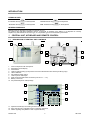
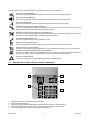
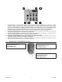
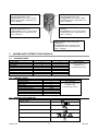
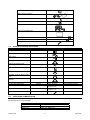
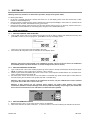
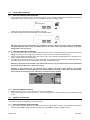
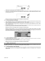
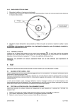
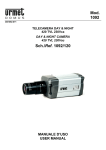
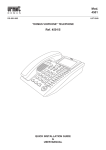
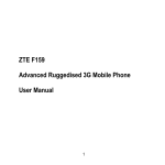
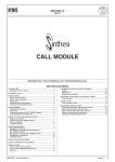
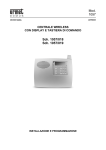
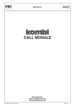
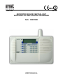
0681
DS1057-002A
LBT 7934
MICROPROCESSOR CENTRAL UNIT
WITH DISPLAY AND CONTROL KEYBOARD
Sch. 1057/008
USER’S MANUAL
SUMMARY
Introduction...................................................................................................................................................... 4
Symbols Used .......................................................................................................................................... 4
General Warnings..................................................................................................................................... 4
1
Central Unit, Keyboard and Remote Control....................................................................................... 4
1.1
Description of Central Unit Controls ............................................................................................ 4
1.1.1
2
3
1.2
Description of the Auxiliary Control Keyboard ............................................................................. 6
1.3
Description of the Remote Control............................................................................................... 7
Alarms and System status Signals....................................................................................................... 8
2.1
External Siren .............................................................................................................................. 8
2.2
Internal Siren................................................................................................................................ 8
s2.3
central Unit Signaling ................................................................................................................... 8
2.4
Auxiliary Control Keyboard .......................................................................................................... 9
2.5
Telephone Communicator............................................................................................................ 9
System Use ........................................................................................................................................... 10
3.1
Total Activation .......................................................................................................................... 10
3.1.1
3.1.2
3.1.3
3.2
With the Central Unit Keyboard ....................................................................................................... 10
With the Auxiliary Keyboard............................................................................................................. 10
With the Remote Control.................................................................................................................. 10
Total Deactivation ...................................................................................................................... 11
3.2.1
3.2.2
3.2.3
3.3
With the Central Unit Keyboard ....................................................................................................... 11
With the Auxiliary Keyboard............................................................................................................. 11
With the Remote Control.................................................................................................................. 11
Partial Activation ........................................................................................................................ 11
3.3.1
3.3.2
3.3.3
3.4
With the Central Unit Keyboard ....................................................................................................... 11
With the Auxiliary Keyboard............................................................................................................. 12
With the Remote Control.................................................................................................................. 12
Partial Deactivation .................................................................................................................... 12
3.4.1
3.4.2
3.4.3
4
Icons and their Meanings................................................................................................................... 5
With the Central Unit Keyboard ....................................................................................................... 12
With the Auxiliary Keyboard............................................................................................................. 13
With the Remote Control.................................................................................................................. 13
3.5
What to do in case of Signaling on the Central Unit .................................................................. 14
System Management............................................................................................................................ 15
4.1
Changing Time and Date ........................................................................................................... 15
4.2
Changing the Access Code ....................................................................................................... 15
4.3
Detectors Exclusion and Inclusion............................................................................................. 16
4.3.1 Detector Exclusion .................................................................................................................................. 16
4.3.2 Detector Inclusion.................................................................................................................................... 16
5
6
Event Chronology................................................................................................................................. 16
5.1
Event List ................................................................................................................................... 16
5.2
How to Interpret Information ...................................................................................................... 17
5.3
Deleting Event memory.............................................................................................................. 17
Telephone Communicator ................................................................................................................... 18
6.1
Using the Keyboard to Insert Alphanumerical Characters......................................................... 18
6.2
Operating Principles................................................................................................................... 18
6.3
Recording the Main Message .................................................................................................... 18
6.4
Main Message Playback ............................................................................................................ 19
6.5
Writing SMS Messages.............................................................................................................. 19
6.6
Deleting SMS Messages............................................................................................................ 20
DS1057-002
2
LBT 7934
6.7
6.8
6.9
6.10
6.11
6.12
SIM Card Expiry Reminder ........................................................................................................ 21
Adding a new TelephonE Number............................................................................................. 22
Changing a Phone Number ....................................................................................................... 22
Deleting A telephone Number.................................................................................................... 23
Interrupting the Cycle Of Alarm Phone Calls ............................................................................. 23
Remote Controlling .................................................................................................................... 23
6.12.1
6.12.2
6.12.3
6.12.4
6.12.5
6.12.6
7
8
Remote Activation / Deactivation Authorization and Revocation ..................................................... 24
Answering Machine.......................................................................................................................... 24
Central Unit Signals ......................................................................................................................... 25
Connecting to the Central Unit......................................................................................................... 25
Remote Controlling Procedure......................................................................................................... 25
Examples ......................................................................................................................................... 25
Trouble Shooting.................................................................................................................................. 26
7.1
The Telephone Line Has No Signal........................................................................................... 26
7.2
The Telephone Line Works But It’s Not Possible to Send Phone Messages............................ 26
7.3
Radio Sabotage Signaling ......................................................................................................... 26
Glossary ................................................................................................................................................ 26
DS1057-002
3
LBT 7934
INTRODUCTION
SYMBOLS USED
► indicates the key
on the keyboard
OK indicates the key
◄ indicates the key
on the keyboard
ESC indicates the key
on the keyboard
on the keyboard
GENERAL WARNINGS
Batteries must be disposed of according to the laws in force.
For products that use lithium batteries, there is a small risk of explosion if the battery is not disposed of correctly.
Replace only with batteries of the same type, or of equivalent type as recommended by the builder.
1
CENTRAL UNIT, KEYBOARD AND REMOTE CONTROL
1.1
DESCRIPTION OF CENTRAL UNIT CONTROLS
1
2
10
4
3
10
7
6
10
4
5
8
1.
2.
3.
4.
5.
6.
7.
8.
9.
10.
9
10
Jack for earphones with microphone.
Keyboard and LCD display.
Internal siren.
Holes for wall mounting (in the picture of the front side the holes are closed by finishing caps).
Lithium batteries.
Anti-violation tamper spring.
Hole for phone cable input.
Relay output terminal board connectors (max 24 Vc.c. – 1 A).
Battery connectors.
Pre-perforated phone cable passage
15
14
13
16
12
11
17
11. Alpha-numerical keys for inserting numbers and letters.
12. Keys used for menu navigation and for confirming operations.
13. Failure signaling LED (blinks in case of system failures).
DS1057-002
4
LBT 7934
14. Liquid crystal display: shows the icons that indicate the system’s status, and the items of the programming menu. At
rest, it alternatively shows the current date and time.
15. Crepuscular sensor (enables the backlighting of the display in the presence of insufficient light).
16. Alarm signaling LED (blinks in the presence of memorized alarms).
17. Function keys (allow quick access to programmed functions).
1.1.1 ICONS AND THEIR MEANINGS
Thanks to the icons that appear on the liquid crystal display, the system’s status can be monitored at a glance. Some
icons are always present, while others appear only when certain events occur.
For details regarding each indication, proceed as follows:
• Press the OK key on the keyboard.
• The first visible icon blinks, and the display shows the generic name of the indication. Use the ► and ◄ keys to move
through the different icons displayed.
• Press the OK key for details regarding the indication (for example «SABOTAGE ON...»).
• Press the ► key again to visualize the other indications of the same type.
• Press ESC key to finish.
Through the low batteries indication or alarm, it’s possible to identify which device has low batteries.
By consulting the details of the alarm memory (sabotage, intrusion alarm, panic alarm), the signal is automatically
deleted if the event that caused the alarm has terminated. The intrusion alarm and sabotage icons are also automatically
deleted when the system is reactivated (the icon is no longer displayed).
The icons regarding the entire system’s battery charge and the activation status of the antitheft zones are always
present.
INDICATION OF BATTERIES OK
All of the system’s batteries have over 50% residual charge.
INDICATION OF BATTERIES AT 50%
One or more of the system’s batteries are charged less than 50%.
BATTERIES LOW
One or more of the system’s batteries are almost flat, and must be replaced within a month. This icon is
shown together with the failure signaling LED (13).
SYSTEM ACTIVE
The “lock” is turned on when one or more system zones are activated.
ZONES ACTIVE
With the system active, the areas of the “house” icon corresponding to active zones are illuminated.
SYSTEM DEACTIVATED
With the system totally deactivated, only the borders of the “house” are shown.
DS1057-002
5
LBT 7934
The following icons are normally not present. They indicate an alarm or a system failure.
SABOTAGE ALARM MEMORY
Is turned on together with the alarm signaling LED (16) to memorize a sabotage-type alarm.
INTRUSION ALARM MEMORY
Is turned on together with the alarm signaling LED (16) to memorize a intrusion-type alarm.
PANIC ALARM MEMORY
Is turned on together with the alarm signaling LED (16) to memorize a panic-type alarm.
SIGNALING OF PSTN TELEPHONE LINE BUSY
Is turned on together with the failure signaling LED (13) to indicate a busy phone line during a test. Only
valid for models equipped with the PSTN communicator module.
ABSENCE OF PSTN TELEPHONE LINE ALARM MEMORY
Is turned on together with the failure signaling LED (13) to indicate and memorize telephone line absence.
Only valid for models equipped with the PSTN communicator module.
SYSTEM MAINTENANCE SIGNAL
Is turned on to signal access to the «TECHNICAL» menu.
DETECTOR ACTIVATION SIGNAL
Is turned on together with the failure signaling LED (13) to indicate the activation of a detector.
DETECTOR DEACTIVATION SIGNAL
Is turned on together with the failure signaling LED (13) to indicate the exclusion of one or more detectors.
ABSENCE OF GSM TELEPHONE LINE ALARM MEMORY
Is turned on together with the failure signaling LED (13) to indicate and memorize GSM telephone line
absence. Only valid for models equipped with the PSTN communicator and GSM modules.
FAILURE ALARM MEMORY
Is turned on together with the failure signaling LED (13) to indicate a failure.
1.2
DESCRIPTION OF THE AUXILIARY CONTROL KEYBOARD
4
3
2
5
1
1.
2.
3.
4.
5.
Alpha-numerical keys for inserting numbers and letters
System status signaling LED
Crepuscular sensor (enables backlighting the keyboard in the presence of insufficient light).
System status signaling LED (green LED = zone deactivated, red LED = zone activated).
Function keys (allow quick access to the programmed functions)
DS1057-002
6
LBT 7934
12
6
7
11
10
8
9
6.
SYSTEM STATUS – Summarizes the system’s status requested by pressing the OK (#) key: green LED = system
activated, nothing to signal; red LED = alarms or system failure. To visualize details, insert a valid access code and
confirm by pressing OK. The information visualized is related to the code inserted. For example it regards only the
zone that can be activated or deactivated with that specific code inserted (in this case, no information is given
regarding the other zones). Press the OK key again to turn off signaling without waiting for the time-out period.
7. DETECTOR DEACTIVATION SIGNAL – Is turned on to indicate the exclusion of one or more detectors.
8. INTRUSION ALARM MEMORY – Memorizes an intrusion-type alarm. The indication is cancelled from the memory
at next system activation if the cause of the alarm is eliminated.
9. FAILURE ALARM MEMORY – Memorizes system failure (the LED blinks). The indication is cancelled from the
memory at next system activation if the cause of the alarm is eliminated.
10. SYSTEM IN MAINTENANCE SIGNAL – Indicates access to the maintenance menu.
11. SABOTAGE ALARM MEMORY – Memorizes a sabotage-type alarm. The indication is cancelled from the memory at
next system activation if the cause of the alarm is eliminated.
12. DETECTOR ACTIVATION SIGNAL – Is turned on to indicate the activation of a detector (for example, a door left
open or someone who moves in front of a volumetric detector).
1.3
DESCRIPTION OF THE REMOTE CONTROL
Short pressure (1 sec):
activation/deactivation zone 1
Long pressure (3 sec):
zone 1 status request
Short Pressure (1 sec):
activation/deactivation zone 2
Long Pressure (3 sec):
zone 2 status request
Short Pressure (1 sec):
total activation/deactivation
Long Pressure (3 sec):
system status request
DS1057-002
7
LBT 7934
Short Pressure (1 sec):
activation/deactivation zone 1
Long Pressure (3 sec): zone 1 status
request (green LED = deactivated, red
LED = activated)
Short pressure (1 sec):
activation/deactivation zone 2
Long pressure (3 sec): zone 2 status
request (green LED = deactivated, red
LED = activated)
Short Pressure (1 sec):
activation/deactivation zone 3
Long Pressure (3 sec): ): zone 3 status
request (green LED = deactivated, red
LED = activated)
Short Pressure (1 sec): total system
activation
Long Pressure (3 sec): system status
request (green LED = deactivated, red
LED = activated)
Short pressure (1 sec): total system
deactivation
Long pressure (3 sec): system status
request (green LED = deactivated, red
LED = activated)
2
2.1
ALARMS AND SYSTEM STATUS SIGNALS
EXTERNAL SIREN
Event
Intrusion alarm
Sabotage alarm
Panic alarm
Sabotage radio alarm
Total system activation
Total system deactivation
Partial system activation
Partial system deactivation
2.2
Blinking
●
1 beep
4 beeps
1 beep
4 beeps
Editable
See paragraph
9.6 External Siren of the
Installation and
Programming manual
●
●
INTERNAL SIREN
Event
Intrusion Alarm
Sabotage Alarm
Panic Alarm
Sabotage Radio Alarm
Total system activation
Total system deactivation
Partial system activation
Partial system deactivation
2.3
Acoustic signal
●
●
●
Acoustic signal
●
●
●
●
1 beep
4 beeps
1 beep
4 beeps
Editable
See paragraph
9.5 Central Unit Siren of the
Installation and
Programming manual
CENTRAL UNIT SIGNALING
Event
Intrusion Alarm
Display
,
Sabotage Alarm
Panic Alarm
Failure Alarm
,
,
Detector Activation Signal
DS1057-002
8
LBT 7934
Detector Deactivation Signal
Battery charge indication
,
,
Signaling of PSTN telephone line busy
Signaling of PSTN telephone line absence
Total system activation
,
Total system deactivation
Partial system activation
House with some numbered zones,
Partial system deactivation
House with some empty zones,
System in maintenance
2.4
AUXILIARY CONTROL KEYBOARD
Event
Intrusion Alarm
ACOUSTIC SIGNAL
LED
Editable
House, all red
House, all green
House, some green, the
remaining red
House, some green, the
remaining red
See Installation Manual
See Installation Manual
See Installation Manual
Sabotage Alarm
Panic Alarm
Failure Alarm
Detector Activation Signal
Detector Deactivation Signal
Batteries charged indication
Signaling of PSTN telephone line
busy
Signaling of PSTN telephone line
absence
Total system activation
Total system deactivation
Partial system activation
2 beeps
2 beeps
2 beeps
Partial system deactivation
2 beeps
See Installation Manual
System in maintenance
2.5
TELEPHONE COMMUNICATOR
If the Sch. 1057/008 central unit is equipped with the PSTN c/modem communicator module, events will be signaled with
the following pre-recorded messages:
Event
Intrusion
Sabotage
Battery Low
DS1057-002
Message
Intrusion alarm. Intrusion alarm.
Sabotage alarm. Sabotage alarm.
Battery low. Battery low.
9
LBT 7934
3
SYSTEM USE
Warning: before any activation or deactivation operation, always check system status.
To check system status:
• on the Sch. 1057/008 central unit, examine the house icon on the display (active zones are showed with a white
number on a black background);
• using the auxiliary control keyboard, insert a valid access code and press OK (#): in the house icon, activated zones
are indicated by red LEDs, deactivated zones by green LEDs;
• using the remote controls, press the xx key (on the 3-key remote control) or key 4 (on the 5-key remote control) for 3
seconds: the red LED indicates an activated system, the green LED a deactivated system.
3.1
TOTAL ACTIVATION
3.1.1 WITH THE CENTRAL UNIT KEYBOARD
1. Insert a valid access code on the central unit keyboard (it must be able to activate and deactivate all zones), and
press OK to confirm (in case of typing error, press ESC to cancel). The display shows:
xxxx
FUNCTION KEYS
2.
where xxxx is the name of the user associated to the code.
Press the key T4: all system zones are activated, and the display shows
Warning: if the access code inserted is not enabled for all zones, only the zones for which it is enabled will
be activated (shown with white numbers on a black background in the icon house).
3.1.2 WITH THE AUXILIARY KEYBOARD
1. Type a valid access code on the auxiliary keyboard (it must be able to activate and deactivate all zones) and press
OK (#) to confirm (in case of typing error, press the * key to cancel).
2. Wait for system status visualization (the LEDs of the “house” on the keyboard are illuminated: red = activated zone,
green = deactivated zone) and press T4.
3. The LEDs of the “house” are turned off, and if activation is successful they will be turned again on after about ten
seconds showing the new status of the system (red LED = activated zone).
Warning: if the access code inserted is not enabled for all zones, only the enabled zones will be activated
(only some of the LEDs of the “house” turn red).
Warning: if after pressing T4, the intrusion alarm memory, the failure alarm memory, the system
maintenance indication and the sabotage alarm memory LEDs are blinking red (see figure), this means that
there has been a transmission error and that the command must be repeated.
3.1.3 WITH THE REMOTE CONTROL
1. Briefly press key 4 (key 3 on the 3-key remote control). Its LED blinks.
2. After a short moment, the LEDs of the keys 1, 2, and 3 turn red for 2 seconds confirming the activation of all zones.
DS1057-002
10
LBT 7934
3.2
TOTAL DEACTIVATION
3.2.1 WITH THE CENTRAL UNIT KEYBOARD
1. On the central unit keyboard, type in a valid access code (it must be able to activate and deactivate all zones) and
press OK to confirm (in case of typing error, press ESC to cancel). The display shows:
xxxx
FUNCTION KEYS
2.
where xxxx is the name of the user associated to the code.
Press T5: all system zones are deactivated, and the display shows
Warning: if the access code inserted is not enabled for all zones, only the zones for which it is enabled will
be deactivated (the other zones will remain active and will be shown with white numbers on a black
background in the icon house).
3.2.2 WITH THE AUXILIARY KEYBOARD
1. Type a valid access code on the auxiliary keyboard (it must be able to activate and deactivate all zones) and press
OK (#) to confirm (in case of typing error, press the * key to cancel). The status LED blinks green.
2. Wait for system status visualization (the LEDs of the “house” on the keyboard are illuminated: red = activated zone,
green = deactivated zone) and press T5.
3. The LEDs of the “house” are turned off, and if deactivation is successful they will be turned on again after about ten
seconds showing the new status of the system (green LED = deactivated zone).
Warning: if the access code inserted is not enabled for all zones, only the enabled zones will be deactivated
(only some of the LEDs of the “house” turn green).
Warning: if after pressing T5, the intrusion alarm memory, the failure alarm memory, the system
maintenance indication and the sabotage alarm memory LEDs are blinking red (see figure), this means that
there has been a transmission error and that the command must be repeated.
3.2.3 WITH THE REMOTE CONTROL
1. Briefly press key 5 (key 3 on the 3-key remote control). Its LED blinks.
2. After a short instant, the LEDs of the keys 1, 2, and 3 turn green for 2 seconds confirming the deactivation of all
zones.
3.3
PARTIAL ACTIVATION
It’s possible to selectively activate one or more zones in order to guarantee anti-intrusion safety in rooms in which we are
not present (for example the garage); proceed as follows.
3.3.1 WITH THE CENTRAL UNIT KEYBOARD
1. On the central unit keyboard, type in a valid access code (it must be able to activate and deactivate the requested
zones) and press OK to confirm (in case of typing error, press ESC to cancel). The display shows:
DS1057-002
11
LBT 7934
xxxx
FUNCTION KEYS
2.
where xxxx is the name of the user associated to the code.
Press the key corresponding to the zone that is to be activated: T1 for zone 1, T2 for zone 2 and T3 for zone 3. The
selected zone is activated, and is shown on the display as a white number on a black background inside the “house”
(in the figure below, zone 1)
Warning: if the zone was already active, this operation will deactivate it.
3.3.2 WITH THE AUXILIARY KEYBOARD
1. Type a valid access code on the auxiliary keyboard (it must enable to activate and deactivate the requested zone)
and press OK (#) to confirm (in case of typing error, press the * key to cancel).
2. Wait for system status visualization (the LEDs of the “house” on the keyboard are illuminated: red = activated zone,
green = deactivated zone) and press the key corresponding to the zone that is to be activated: T1 for zone 1, T2 for
zone 2 and T3 for zone 3.
3. The LEDs of the “house” are turned off, and if activation is successful they will be turned on again after about 10
seconds showing the system’s new status (red LED = activated zone).
Warning: if the zone was already active, this operation will deactivate it.
Warning: if after pressing T1, T2, or T3, the intrusion alarm memory, the failure alarm memory, the system
maintenance indication and the sabotage alarm memory LEDs are blinking red (see figure), this means that
there has been a transmission error and that the command must be repeated.
3.3.3 WITH THE REMOTE CONTROL
1. Briefly press the key of the zone to be activated: 1 for zone 1, 2 for zone 2 and 3 for zone 3 (1 for zone 1, 2 for zone
2 on the 3-key remote control). Its LED blinks.
2. After a short moment, the LED turns red for 2 seconds to confirm zone activation.
Warning: if the zone was already active, this operation will deactivate it.
3.4
PARTIAL DEACTIVATION
It’s possible to deactivate one or more zones in order to allow access to selected rooms (for example the living room),
while other areas in which we are not present remain protected. Proceed as follows.
3.4.1 WITH THE CENTRAL UNIT KEYBOARD
1. Type a valid access code on the auxiliary keyboard (it must enable to activate and deactivate the requested zone)
and press OK to confirm (in case of typing error, press the ESC key to cancel). If, for example, zone 1 is active, the
display shows:
DS1057-002
12
LBT 7934
xxxx
FUNCTION KEYS
2.
where xxxx is the name of the user associated to the code, and the active zones are indicated by a white number on
a black background inside the “house”.
Press the key corresponding to the zone to be deactivated: T1 for zone 1, T2 for zone 2 e T3 for zone 3. The
selected zone is deactivated, and is no longer indicated on the display inside the “house”
Warning: if the zone was already deactivated, this operation will activate it.
3.4.2 WITH THE AUXILIARY KEYBOARD
1. Type a valid access code on the auxiliary keyboard (it must enable to activate and deactivate the requested zone)
and press OK (#) to confirm (in case of typing error, press the * key to cancel). The status LED blinks green.
2. Wait for system status visualization (the LEDs of the “house” on the keyboard are illuminated: red = zone activated,
green = zone deactivated) and press the key corresponding to the zone to be activated: T1 for zone 1, T2 for zone 2
and T3 for zone 3.
3. The LEDs inside the “house” are turned off, and if activation is successful they turn on again after 10 seconds
showing the system’s new status (green LED = zone deactivated).
Warning: if the zone was already deactivated, this operation will activate it.
Warning: if after pressing T1, T2, or T3, the intrusion alarm memory, the failure alarm memory, the system
maintenance indication and the sabotage alarm memory LEDs are blinking red (see figure), this means that
there has been a transmission error and that the command must be repeated.
3.4.3 WITH THE REMOTE CONTROL
1. Briefly press the key of the zone to be deactivated: 1 for zone 1, 2 for zone 2 and 3 for zone 3 (1 for zone 1, 2 for
zone 2 on the 3–key remote control). Its LED blinks.
2. After a short moment, the LED turns red for 2 seconds to confirm zone activation.
Warning: if the zone was already deactivated, this operation will activate it.
DS1057-002
13
LBT 7934
3.5
WHAT TO DO IN CASE OF SIGNALING ON THE CENTRAL UNIT
In case of signals on the central unit, the first thing to do is understand signal details according to the procedure indicated
in paragraph 1.1.1
Icons and their Meanings. Then, identify possible causes and solutions using the following
table.
Icons
Signal Details
Central unit sabotage, device
sabotage
Radio sabotage / jamming
False code
Detector intrusion
PSTN network absent
GSM network absent
System maintenance
Alarm memory failure
Batteries low
DS1057-002
Cause
• Someone tried to remove or
open the device, activating
the anti-violation tamper
• the device is not correctly
mounted on the wall (or its
cover is not perfectly closed)
The radio channel is disturbed
The wrong code has been
inserted for 4 times consecutively
with the system active (possible
attempt of fraudulent
deactivation)
With the system activated, the
indicated detector has been
triggered (for example through
the magnetic contacts by
opening a protected door or
window, or through the
volumetric movement sensors)
The PSTN communicator module
does not detect line voltage on
the telephone line
• The GSM module does not
detect the presence of the
GSM phone network
• SIM Card missing
• SIM Card expired or with no
credit
The technical menu has been
activated
Failure
One or more batteries of the
central unit or other system
devices are low and must be
replaced within a month (to
identify the device with low
batteries, press OK on the
central unit keyboard)
14
Solution
Re-fasten the device or properly
close the cover until the antiviolation tamper is correctly
pressed; subsequently check that
the sabotage alarm is no longer
indicated
First check that it is not caused by
an occasional disturbance (electric
motor, non shielded electronic
device): in this case, remove the
device that is causing the
disturbance or provide appropriate
shielding; in all other cases, it is to
be considered a hostile act on
behalf of a criminal
•
check if there has been an
intrusion attempt, if doors or
windows
with
magnetic
sensors are closed correctly,
and that there are no moving
objects (i.e. ceilings fans,
curtains or air conditioning
flows) or rays of direct or
reflected sunlight that may
deceive the infrared detectors;
verify that the alarm is no
longer signaled
• if no solution is found,
temporarily
deactivate
the
detector (see paragraph 4.3
Detectors Exclusion and
Inclusion) and immediately
contact your installer
See paragraph
7
Trouble Shooting on page
26
Insert the SIM Card,
reactivate or recharge the SIM
Card
Press the ESC key to exit the
«TECHNICAL» menu
See other active signals for details
regarding the failure
Immediately contact your installer
in order to replace the batteries of
the indicated devices
LBT 7934
4
4.1
SYSTEM MANAGEMENT
CHANGING TIME AND DATE
The display of the central unit alternatively shows the time and date. This information is included in every occurrence of
the event memory. To change the time and date, for example for switching to daylight saving time, proceed as follows:
1. Type the Master access code on the central unit keyboard and press OK to confirm.
2. Using the ► key, select the «SETTINGS» menu; press OK to confirm. The display shows:
SETTING
TIME AND DATE
3.
Press OK. The display shows:
TIME AND DATE
SET TIME
4.
Press OK. The display shows:
SET TIME
(HHMM) hhmm
5.
where hh indicates the hours and mm the minutes set. Type in the current hours (from 00 to 23) and minutes (from
00 to 59) and press OK to confirm.
Press OK. The display shows:
TIME AND DATE
SET DATE
6.
Press OK. The display shows:
SET DATE
DD/MM/YY ddmmyy
7.
4.2
where dd is the day, mm the month and yy the year set. Type in the day (from 00 to 31), the month (from 01 to 12)
and the last two digits of the current year and press OK to confirm.
Press the ESC key repeatedly to exit the menu.
CHANGING THE ACCESS CODE
Each user can change his access code by proceeding as follows:
1. Type the current access code on the central unit keyboard and press OK to confirm.
2. Using the ► key, select the «SETTINGS» menu; press OK to confirm.
3. Using the ► key, select the «CODE SETTINGS» menu; press OK to confirm. The display shows:
CODE
nnnn
4.
where nnnn is the current code.
Type in a new 4-digit code different from the predefined codes (1234 and from 0000 to 0016); press OK to confirm.
The display shows:
DS1057-002
15
LBT 7934
RE-INSERT CODE
5.
4.3
Re-insert the new code, and press OK to confirm. Press ESC repeatedly to exit the menu.
DETECTORS EXCLUSION AND INCLUSION
It’s possible to intentionally include or exclude volumetric sensors, magnetic contacts and magnetic contact auxiliary
detectors. This function may be useful, for example, to temporarily isolate a broken detector that continuously signals an
alarm, allowing to therefore activate the antitheft system.
Warning: the exclusion function is an emergency solution only; the detector must be replaced and included as
soon as possible in order to maintain the level of safety guaranteed by the system.
4.3.1 DETECTOR EXCLUSION
To execute a partial reset, proceed as follows:
1. Insert the Master access code and press OK to confirm.
2. Using the ► key, select the « TECHNICAL » menu and press OK to confirm.
3. Insert the Technical access code and press OK to confirm.
4. Using the ► key, select the «SETTINGS» menu and press OK to confirm.
5. Using the ► key, select the «EXCLUSION/INCLUSION SETTINGS» menu and press OK to confirm.
6. The list of detectors is visualized. Using the ► key, select the detector to exclude and press OK to confirm.
7. Using the ► key, select the menu « EXCLUSION/INCLUSION EXCLUSION» and press OK to confirm.
8. Press ESC repeatedly to exit the menu.
4.3.2 DETECTOR INCLUSION
To execute a partial reset, proceed as follows:
1. Insert the Master access code and press OK to confirm.
2. Using the ► key, select the «TECHNICAL» menu and press OK to confirm.
3. Insert the Technical access code and press OK to confirm.
4. Using the ► key, select the «SETTINGS» menu and press OK to confirm.
5. Using the ► key, select the «EXCLUSION/INCLUSION SETTINGS» menu and press OK to confirm.
6. The list of detectors is visualized. Using the ► key, select the detector to include and press OK to confirm.
7. Using the ► key, select the menu « EXCLUSION/INCLUSION INCLUDED» and press OK to confirm.
8. Press ESC repeatedly to exit the menu.
5
EVENT CHRONOLOGY
The last 128 events that regard the system (activation and deactivation, intrusion attempts, sabotage attempts, low
battery signals, no PSTN line, absence of GSM network, etc.) are stored in the central unit’s memory.
5.1
EVENT LIST
To visualize the list of events, proceed as follows:
1. Insert the Master access code on the central unit keyboard and press OK to confirm.
2. Using the ► key, «EVENT MEMORY» menu and press OK to confirm. The display shows:
EVENT MEMORY
READ MEMORY
3.
Press OK to confirm. The display shows the list of events memorized, starting from the most recent (number 001),
like in the example shown below:
●001 08:30 01/01
VALID CODE
4.
5.
Press OK to read event details or the ► and ◄ keys to visualize the preceding or following events.
After consulting the event memory, press ESC repeatedly to exit the menu.
DS1057-002
16
LBT 7934
5.2
HOW TO INTERPRET INFORMATION
In the event memory, the following information is supplied for each event:
• Event start and finish (● = start, ○ = finish);
• Event’s progressive number (lower numbers indicate more recent events);
• Event time and date. WARNING: time and date values are the ones set on the central unit; regarding the date, only
the day and month are memorized;
• Specific event information
Examples
●012 08:30 16/03
VALID CODE
Event number 12: at 8.30 of March 16 a valid access code was inserted.
○095 14:27 03/01
MAINTENANCE
Event number 95 (precedes event 12): at 14.27 of January 3 the central unit exited the technical menu.
5.3
DELETING EVENT MEMORY
Warning: Deleting is an irreversible operation. For event memory operation, it’s not necessary to delete
memorized events since the Sch. 1057/008 central unit automatically eliminates the oldest event once 128
events are reached.
To delete memorized events proceed as follows:
1. Insert the Master access code and press OK to confirm.
2. Using the ► key, select the « TECHNICAL MENU» and press OK to confirm.
3. Insert the Technical access code and press OK to confirm.
4. The «EVENT MEMORY» menu is visualized: press OK to confirm. The display shows:
EVENT MEMORY
DELETE MEMORY
5.
6.
Press OK to confirm. Using the ► key, select the «CONFIRM YES» menu and press OK to confirm.
The display shows:
EVENT MEMORY
DELETED
7.
confirming deletion.
Press ESC repeatedly to exit the menu.
DS1057-002
17
LBT 7934
6
TELEPHONE COMMUNICATOR
Warning: all the functions illustrated in this chapter are available only for the Sch. 1057/008 central units
equipped with the PSTN c/modem communicator module and connected to the telephone network (PSTN or
GSM, if the central unit is also equipped with the GSM module).
6.1
USING THE KEYBOARD TO INSERT ALPHANUMERICAL CHARACTERS
The central unit’s keyboard allows to type alphanumerical characters. Each key allows to select one or more characters,
as shown in the table below. The blinking cursor indicates the insertion point of the new character. To type in using the
keyboard (when required):
• Repeatedly press the key associated to the character desired until it appears,
• Use the ► and ◄keys to move to the previous or following position (to delete unnecessary characters, use the
[space] character),
• press OK to memorize the name, or ESC to exit the procedure without memorizing.
Key
1
2
3
4
5
6
7
8
9
0
*
#
6.2
Characters
1@.,;:!“$%&/()+=?‘_-<>
ABCabc2
DEFdef3
GHIghi4
JKLjkl5
MNOmno6
PQRSpqrs7
TUVtuv8
WXYZwxyz9
0 [space] +
*
#
OPERATING PRINCIPLES
In case of alarm, the Sch. 1057/008 central unit equipped with the communicator module (with enabled tone control):
• calls the first phone number configured to send alarm messages regarding the event;
• if the number called answers, it sends the message, hangs up and calls the next number;
• if the number called does not answer within 6 rings, it hangs up and calls the next number;
• after calling all the configured numbers, it retries to call all the numbers that did not answer the first time (at the most,
3 attempts for each phone number); the numbers that already answered are not recalled.
The voice message sent is composed of the main message followed by the specific message pre-recorded for that
particular event.
Example
Imagine there is a sabotage attempt and that the configured phone numbers for this event are Telephone 1 (voice),
Telephone 2 (voice), Telephone 4 (digital protocol) and Telephone 6 (SMS). Furthermore, imagine that Telephone 2, at
the time of the call, is busy and does not answer.
The sequence of phone calls made by the Sch. 1057/008 central unit will be the following:
Telephone1 – Telephone2 – Telephone 4 – Telephone 6 – Telephone 2 – Telephone 2.
6.3
RECORDING THE MAIN MESSAGE
The objective of the main message is to notify where the event that caused the alarm is taking place. For example, the
main message could be «Home of Ambrogio Brambilla, via Roma 56, Milan» or «Bar Al Chicco d’Oro, piazza Gauguin,
Rome».
To record the main message, use the supplied earphone with microphone. The earphone plug must be inserted into the
apposite jack located on the upper side of the central unit (see figure on page 4). Then proceed as follows:
1. Insert the Master access code and press OK to confirm.
2. Using the ► key, select the «PHONE TRANSMIT.» menu and press OK to confirm.
3. Using the ► key, select the «VOICE MESSAGE» menu and press OK to confirm. The display shows:
DS1057-002
18
LBT 7934
VOICE MESSAGE
PLAYBACK
4.
Using the ► key, select the «RECORDING» menu and press OK to confirm. The display shows:
RECORDING.
MAIN MESSAGE
5.
6.
6.4
Press OK. After a short moment, a double beep in the earphone signals to start recording the main message. After
about ten 10 seconds, a new double beep will signal the end of the recording.
Press ESC repeatedly to exit the menu.
MAIN MESSAGE PLAYBACK
To playback the main message, use the supplied earphone with microphone. The earphone plug must be inserted into
the apposite jack located on the upper side of the central unit (see figure on page 4). Then proceed as follows:
1. Insert the Master access code and press OK to confirm.
2. Using the ► key, select the «PHONE TRANSMIT.» menu and press OK to confirm.
3. Using the ► key, select the «VOICE MESSAGE» menu and press OK to confirm. The display shows:
VOICE MESSAGE
PLAYBACK
4.
Press OK to confirm. The display shows:
PLAYBACK
MAIN MESSAGE
5.
Press OK to confirm. The display shows:
MAIN MESSAGE
PLAYBACK........
6.
6.5
and after a short moment the recorded message will be played.
After message playback, press ESC repeatedly to exit the menu.
WRITING SMS MESSAGES
Warning: this function requires the installation of the GSM module.
It allows to write and memorize the SMS messages that the GSM module will send if an alarm event should occur. The
message may be at the most 40 characters long, including spaces.
To write SMS messages, proceed as follows:
1. Insert the Master access code on the central unit keyboard and press OK to confirm.
2. Using the ► key, select the «TECHNICAL MENU» and press OK to confirm.
3. Insert the Technical access code and press OK to confirm.
4. Using the ► key, select the «PHONE TRANSMIT.» menu and press OK to confirm. The display shows:
DS1057-002
19
LBT 7934
PHONE TRANSMIT.
TELEPHONE NUMBERS
5.
Using the ► key, select the «ADVANCED 1» menu and press OK. The display shows:
ADVANCED 1
TELESURVEIL CODE
6.
Using the ► key, select the «WRITE SMS» menu and press OK. The display shows:
WRITE SMS
INTRUSION
7.
Using the ► key, select the type of event to which the SMS refers to, and press OK to confirm.
The display shows:
xxxx
8.
where xxxx is the type of event selected. Insert the SMS message using the keyboard (for further information, see
paragraph 6.1
Using the Keyboard to Insert Alphanumerical Characters).
Press OK to confirm. The display shows:
WRITE SMS
XXXX
9.
6.6
In order to write other SMS messages, use the ► key to select the appropriate event, press OK to confirm and
repeat from point 7.
Press ESC repeatedly to exit the menu.
DELETING SMS MESSAGES
Warning: this function requires the installation of the GSM module.
Allows to delete previously memorized SMS messages.
To delete an SMS message, proceed as follows:
1. Type in the Master access code on the central unit keyboard and press OK to confirm.
2. Using the ► key, select the «TECHNICAL MENU» and press OK to confirm.
3. Insert the Technical access code and press OK to confirm.
4. Using the ► key, select the «PHONE TRANSMIT.» menu and press OK to confirm. The display shows:
PHONE TRANSMIT.
TELEPHONE NUMBERS
5.
Using the ► key, select the «ADVANCED 1» menu and press OK to confirm. The display shows:
DS1057-002
20
LBT 7934
ADVANCED 1
TELESURVEIL CODE
6.
Using the ► key, select the «DELETE SMS» menu and press OK to confirm. The display shows:
DELETE SMS
INTRUSION
7.
Using the ► key, select the type of event to which the SMS to be deleted must refer, and press OK to confirm.
The display shows:
xxxx
CONFIRM NO
8.
where xxxx is the type of event selected. Using the ►key, select «CONFIRM YES» and press OK.
The display shows:
DELETE SMS
XXXX
9.
6.7
In order to delete other SMS messages, use the ► key to select the event to which they refer, press OK to confirm
and repeat from point 7.
Press ESC repeatedly to exit the menu.
SIM CARD EXPIRY REMINDER
Warning: this function requires the installation of the GSM module.
Sends the previously recorded SMS message «SIM EXPIRY» (see paragraph 6.5
Writing SMS Messages) on the
first day of the month selected as a reminder for upcoming SIM Card expiry. To insert the reminder, proceed as follows:
1. Type in the Master access code on the central unit keyboard and press OK to confirm.
2. Using the ► key, select the « TECHNICAL MENU » and press OK to confirm.
3. Insert the Technical access code and press OK to confirm.
4. Using the ► key, select the «PHONE TRANSMIT.» menu and press OK to confirm. The display shows:
PHONE TRANSMIT.
TELEPHONE NUMBERS
5.
Using the ► key, select the «ADVANCED 1» menu and press OK to confirm. The display shows:
ADVANCED 1
TELESURVEIL CODE
6.
Using the ► key, select the «SIM EXPIRY» menu and press OK to confirm. The display shows:
DS1057-002
21
LBT 7934
SIM EXPIRY
mmyy
7.
8.
where mmyy indicates the month and year memorized.
Using the keyboard, insert the month previous to expiry, and the last two digits of the year of expiry of the
rechargeable SIM Card. For example, if the SIM Card expires in May 2007, type “0407”. Press OK to confirm.
Press ESC repeatedly to exit the menu.
Warning: in order to supply correct results, this function requires the correct setting of the date on the central
unit Sch. 1057/008 (se paragraph 4.1
Changing Time and Date).
6.8
ADDING A NEW TELEPHONE NUMBER
It’s possible to memorize up to 6 phone numbers that the central unit will call if specific events should occur. Each
number may be long from 3 to 28 characters (digits or pauses). To add a new phone number proceed as follows:
1.
2.
Type the Master access code on the central unit keyboard and press OK to confirm.
Using the ► key, select the «PHONE TRANSMIT.» menu and press OK to confirm. The display shows:
PHONE TRANSMIT.
TELEPHONE NUMBERS
3.
Press OK. The first memory position for phone numbers appears:
TELEPHONE NUMBERS.
N.1:
4.
5.
6.
7.
8.
6.9
If a phone number has already been memorized it appears after «N.1:».
Using the ► key, select the desired memory position and confirm it by pressing OK.
Using the keyboard, insert the desired phone number. To insert a pause, press the ► key (the letter P appears). To
delete the number press ESC. To modify a wrong digit, press the ◄ key until the cursor is positioned above that digit
and insert the correct value.
Press OK to memorize the new phone number.
In order to insert other phone numbers, select a free memory position using the ► key, and repeat from point 5.
Press ESC repeatedly to exit the menu.
CHANGING A PHONE NUMBER
It’s possible to modify the phone numbers that the central unit will call if specific events should occur. To modify a phone
number proceed as follows:
1.
2.
Type the Master access code on the central unit keyboard and press OK to confirm.
Using the ► key, select the «PHONE TRANSMIT.» menu and press OK to confirm. The display shows:
PHONE TRANSMIT.
TELEPHONE NUMBERS
3.
Press OK. The first memory position for phone numbers appears:
TELEPHONE NUMBERS
N.1:
4.
Using the ► key, select the phone number to be modified and confirm it by pressing OK.
DS1057-002
22
LBT 7934
5.
6.
7.
8.
Delete the existing number by pressing ESC, and insert the new phone number using the keyboard (long up to 28
characters of digits or pauses). To insert a pause, press the ► key (the letter P appears). To delete the number
press ESC. To modify a wrong digit, press the ◄ key until the cursor is positioned above that digit and insert the
correct value.
Press OK to memorize the new phone number.
In order to modify other phone numbers, select them by using the ► key and repeat from point 4.
Press ESC repeatedly to exit the menu.
6.10 DELETING A TELEPHONE NUMBER
It’s possible to delete any one of the phone numbers that the central unit will call if specific events should occur. To
delete a phone number proceed as follows:
1.
2.
Type the Master access code on the central unit keyboard and press OK to confirm
Using the ► key, select the «PHONE TRANSMIT.» menu and press OK to confirm. The display shows:
PHONE TRANSMIT.
TELEPHONE NUMBERS
3.
Press OK. The first memory position for phone numbers appears:
TELEPHONE NUMBERS
N.1:
4.
5.
6.
7.
Using the ► key, select the phone number to be deleted and confirm it by pressing OK.
Delete the existing number by pressing ESC and press OK to confirm.
In order to delete other phone numbers, select them using the ► key and repeat from point 5.
Press ESC repeatedly to exit the menu.
6.11 INTERRUPTING THE CYCLE OF ALARM PHONE CALLS
The phone alarm message is repeated 3 times, as shown in the following scheme where “main message” is the
personalized message recorded by the user (for example «Home of Paolo Verdi, via Roma 15, Milan») and “event
message” is the specific alarm message pre-recorded at the plant (see paragraph 2.5
Telephone Communicator on
page 9).
10 s
5s
0,5 s
5s
Main Message
Event Message
Beep
Delay until locking
Main Message
Event Message
Beep
Delay until locking
Main Message
Event Message
Beep
Delay until locking
During message playback, it’s possible to interrupt the repetition of the current voice message by typing the code 22 on a
push-button phone with DTMF tones, as in the example that follows.
10 s
5s
0,5 s
5s
Main Message
Event Message
Beep
Delay until locking
TYPE 22
CYCLE BLOCKED
It is also possible to interrupt the sequence of all calls by typing a valid access code on the keyboard. This function is
very useful when more than one phone number has been configured to receive that type of alarm (for example office,
personal mobile phone and parents) and, after receiving the first alarm, it is not necessary that the alarm is notified to
others.
6.12 REMOTE CONTROLLING
With a DTMF tone telephone, it’s possible to remotely control the Sch. 1057/008 central unit equipped with PSTN
c/modem communicator module. The possible actions are:
• activation of the anti-theft system (requires previous authorization, see the following paragraph);
• deactivation of the anti-theft system (requires previous authorization, see the following paragraph);
• activation of the central unit’s relay A auxiliary output;
• activation of the central unit’s relay B auxiliary output.
DS1057-002
23
LBT 7934
If an alarm should occur during the remote controlling procedure, the central unit emits a long beep and refuses
activation or deactivation commands: it’s necessary to interrupt the control procedure and free the phone line.
6.12.1 REMOTE ACTIVATION / DEACTIVATION AUTHORIZATION AND REVOCATION
To carry out remote activation and deactivation of the antitheft system, it’s necessary to authorize the “answer incoming
calls” function of the central unit. The central unit in this case will answer incoming calls except when an alarm signal is
being sent.
To authorize the answer to incoming calls:
1. Insert the Master access code and press OK to confirm.
2. Using the ► key, select the «TECHNICAL MENU» and press OK to confirm.
3. Insert the Technical access code and press OK to confirm.
4. Using the ► key, select the «PHONE TRANSMIT.» menu and press OK to confirm.
5. Using the ► key, select the «PHONE TRANSMIT. ADVANCED 1» menu and press OK to confirm.
6. Using the ► key, select the «ADVANCED 1 ANSWERING DEVICE» menu and press OK to confirm. The display
shows:
ANSWERING DEVICE
PSTN
7.
Press OK to confirm. The display shows:
PSTN ANSWER DEVICE
DEACTIVATE
8.
9.
Using the ► key, select the number of rings (2, 4 or 8) after which the central unit will answer incoming calls and
press OK to confirm.
Press ESC repeatedly to exit the menu.
To revoke the answering of incoming calls:
1. Insert the Master access code and press OK to confirm.
2. Using the ► key, select the « TECHNICAL MENU » and press OK to confirm.
3. Insert the Technical access code and press OK to confirm.
4. Using the ► key, select the «PHONE TRANSMIT.» menu and press OK to confirm.
5. Using the ► key, select the «PHONE TRANSMIT. ADVANCED 1» menu and press OK to confirm.
6. Using the ► key, select the «ADVANCED 1 ANSWERING DEVICE» menu and press OK to confirm. The display
shows:
PSTN
ANSWERING DEVICE
7.
Press OK to confirm. The display shows:
PSTN ANSWERING DEVICE
n RINGS
8.
9.
where n indicates the number of rings after which the central unit responds to incoming calls.
Using the ► key, select the «DEACTIVATE» menu to deactivate answering incoming calls and press OK to confirm.
Press ESC repeatedly to exit the menu.
6.12.2 ANSWERING MACHINE
If the same PSTN telephone line requires the installation of an answering machine, the central unit must respond after a
number of rings greater than that of the answering machine (for the related instructions, se paragraph 6.12.4 Connecting
to the central unit).
DS1057-002
24
LBT 7934
In this case, to connect to the central unit, it necessary to:
1. Call the central unit’s phone number.
2. After the first ring, hang up. The central unit will respond to the first incoming call after the first ring.
3. Connect to the central unit as explained paragraph 6.12.4 Connecting to the Central Unit.
6.12.3 CENTRAL UNIT SIGNALS
To communicate the results of the commands, the central unit sends out acoustic signals:
• a beep-beep 0,5 seconds long to confirm the correct reception and acceptance of the numbers inserted;
• a long beep to indicate:
• a programmed output different from “Service”;
• wrong access code;
• wrong command.
6.12.4 CONNECTING TO THE CENTRAL UNIT
To connect to the central unit:
1. Dial the central unit’s phone number
2. The central unit responds with a beep-beep after the number of configured rings (to change the number of rings see
chapter 6.12.1
Remote Activation / Deactivation Authorization and Revocation).
3. After the central unit has confirmed connection, move on to the remote controlling procedure.
6.12.5 REMOTE CONTROLLING PROCEDURE
Follow the procedure illustrated below to control the central unit Sch. 1057/008 from a distance.
Step
1
2
Required Action
Phone connection to the
central unit
User authentication
3
4
End of authentication
Type of command
send
5
In case of relay output
switching, specify the
related output
6
In case of system status
switching,
specify
activation or deactivation
to
Digits to type on the
keyboard
PSTN line phone number
Central Unit’s Signal
Master
digits)
beep-beep (0,5 seconds)
beep-beep (0,5 seconds)
beep-beep (0,5 seconds)
beep-beep (0,5 seconds)
beep-beep (0,5 seconds)
beep-beep (0,5 seconds)
First digit received
Second digit received
Third digit received
Fourth digit received
Code accepted
Type
of
command
received
beep-beep (0,5 seconds)
+ “Output A activated” or
“Output B activated”
Command
successful
(Warning: indicates that
the relay has been
correctly closed
and
reopened, not that the
device connected to the
relay worked correctly)
Command successful
user
code
(4
#
3 = switching system
status, or
5 = switching relay
outputs
1 = relay output A
or
2 = relay output B
1 = system activation
0 = system deactivation
Answer tone
beep-beep (0,5 seconds)
+ “System Activated”
beep-beep (0,5 seconds)
+ “System deactivated”
Meaning of the central
unit’s signal
Connection successful
Command successful
A beep-beep-beep-beep-beep-beep of the central unit indicates an error and that the command has not been executed;
the entire procedure must be repeated.
6.12.6 EXAMPLES
Command
Activation of the antitheft system
Deactivation of the antitheft system
Activation of the relay A auxiliary
output
Activation of the relay B auxiliary
output
DS1057-002
Actions required after connecting to the central unit
“Access code” + #31
After listening to the activation confirmation message, hang up
“Access code” + #30
After listening to the deactivation confirmation message, hang up
“Access code” + #511
After listening to activation confirmation message, hang up
“Access code” + #521
After listening to the activation confirmation message, hang up
25
LBT 7934
7
TROUBLE SHOOTING
7.1
THE TELEPHONE LINE HAS NO SIGNAL
Connect a telephone to the phone line used by the Sch. 1057/008 central unit: if there is no free phone line signal it
means that the phone line is not active, and that it’s necessary to contact your local telephone operator carrier.
If the phone line is active, but the central unit continues to signal no phone line, contact your installer to check that the
connection between the central unit Sch. 1057/008 and the phone line has not been damaged.
7.2
THE TELEPHONE LINE WORKS BUT IT’S NOT POSSIBLE TO SEND PHONE MESSAGES
If the Sch. 1057/008 central unit does not signal an absent telephone line, but it’s still not possible to send phone
messages, check the following:
• If the central unit is connected to the local phone network through a switchboard, be sure that it has been configured
correctly (see paragraph 9.11.1 PSTN Parameters of the Installation and Programming Manual);
• If the central unit uses the GSM module, be sure that the SIM Card, if rechargeable, has not run out of credit.
7.3
RADIO SABOTAGE SIGNALING
Radio sabotage signaling may be caused by two circumstances:
1. a fraudulent attempt to violate the alarm system: if this is the case, contact your installer for a general inspection,
and if necessary recover the system’s full efficiency.
2. changes in the environment in which the system operates: check that the signaled device is not covered by material
that blocks the passage of radio waves, or that in the vicinity there are no electric motors, household appliances, or
electrical or electronic devices in operation (some devices on the market do not comply with specific standards and
may cause radiofrequency interference). Remove material or turn off these devices if present. If the problem
persists, contact your installer.
8
GLOSSARY
Chimegong
DTMF
GSM
Jamming
PSTN
SIM Card
Tamper
Zone
DS1057-002
Acoustic warning used to automatically signal the arrival of a person.
Acronym for Dual Tone Multi Frequency. Indicates the “tone” composition mode of a phone, as apposed
to “decadic”.
Acronym for Global System for Mobile. Indicates an international standardized system for mobile digital
telecommunications (in other words “cellular” phones).
Intentional disturbance – by means of interference, high power broadcasting, masking – used to block
the reception of comprehensible radio signals.
Acronym for Public Switched Telephone Network. Indicates the entire analogue phone network and in
general any analogue phone line.
Card that identifies the subscriber of a mobile phone service, and that must be inserted into the cellular
phone or equivalent device.
A device’s micro-contact protection
Each of the areas that compose an anti-intrusion system. Dividing the rooms that are to be protected and
the protection devices into more than one zone is recommended, since it enables to activate, if
necessary, only the required detectors. The result is an increase in safety, and greater comfort because
rooms that do not require our presence are protected, while it’s possible to move freely in others.
26
LBT 7934
NOTE
DS1057-002
27
LBT 7934
IS0231-AB
DS1057-002A
SUBSIDIARIES
20151 MILANO – Via Gallarate 218
Tel. 02.380.111.75 – Fax 02.380.111.80
00043 CIAMPINO (ROMA) Via L. Einaudi 17/19A
Tel. 06.791.07.30 – Fax 06.791.48.97
80013 CASALNUOVO (NAPOLI)
Via Nazionale delle Puglie 3
Tel. 081.193.661.20 – Fax 081.193.661.04
30030 VIGONOVO (VENEZIA) – Via del Lavoro 71
Tel. 049.738.63.00 r.a. – Fax 049.738.63.11
DS1057-002
LBT7933
PLANT
URMET DOMUS S.p.A.
10154 TORINO (ITALY)
VIA BOLOGNA 188/C
Telef.
011.24.00.000 (RIC.AUT.)
Fax
011.24.00.300-323
Call Center 011.23.39.801
http://www.urmetdomus.it
28
e-mail: [email protected]
LBT 7934