1
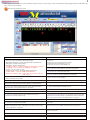
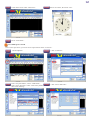
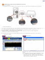
Multimedia 2006 Software User Manual
General information
Screen layout and overview
1
Beginning Text Messaging
Get system information
Select communication mode
Create text
2
2
3
Advanced Text Messaging
5
Insert Bitmap file
6
Insert real-time clock
Insert countdown
7
Insert temperature
8
8
Insert variable
Insert symbol
9
Pre-define message show day(s) and time
10
11
Pre-define power on/off
12
Adjust brightness
Set password
13
Send messages to sign(RS232 communication) --- - - ---- - - 14
Send messages to group of signs--1(RS485 communication)--15
Send messages to group of signs--2(RS485 communication)--18
Send messages to sign-3( TCP/IP communication)
- - - - -21
Send messages to sign-4( TCP/IP communication
of network) - - - ---- - - ---- - - -23
Make font - - - - ---- - - ---- - - ---- - - - ---- - - ---- - - ---- - - 25
Update firmware -- - - ---- - - ---- - - ---- - - ---- - - ---- - - -- 27
Set GSM communication ---- - - ---- - - ---- - - ---- - - ---- 28
Set circle play of messages ---- - - ---- - - ---- - - ---- - - - 28
1
General Information
Messaging software allows you to send message from a PC to your sign. After you install the Messaging Software and start it up,
then you can see as below:
Screen layout and overview
B
A
D
E F G AF H I J AE N
K
O
C
R
Q
P
T
S
L
M
V
W
X
Z
Y
U
AC
AB
A--Font: From five rows to 31 rows in Height
C–Function Menu: Include
“Preview”: to preview the effect of message on sign;
“Multimedia Download”: used for TCP/IP or Rs485 communication;
“Image Edit”: used for creating images;
“Font Make”: used for creating fonts;
“Language Editor”:used for creating new languages of software .
“Language”:you can select the language of software.
“Fonts”:you can select the font.
“Check for a new version”: used to get update software news.
“GPRS Admin”:used for GPRS communication.
“Run when windows start”:select this ,the software will run
with your pc.
AD
B–Color: 12 color available .
D–Options:
In this menu, you can set parameters, such as
communication mode, Brightness, power
on/off time, password, screen number, etc.
E–Insert Bitmap: Insert graphics created in “Image Edit”.
F–Insert datetime: Insert real-time clock.
G – Insert countdown : Insert countdown time and date.
H–Insert temperature: Insert temperature.
( Note: need hardware to work)
I – Insert variable : Insert variable.
J – Insert symbol : Insert pre-defined symbols.
K – X-Port Tool : Used for searching or editing IP Address of sign.
L – Download Fonts : 8 fonts available: ( Note: After you update
firmware or create new Fonts on this software, you must click it.
M – About : Get information about this software.
N – New Line : Click it to stat a new line. (Note: You must set this
function under “Environment Setup” in “Options”)
O – Align : Include Align Left/Right/Cen ter.
P – Download : Send messages to sign.
Q – Save as : Save *.mld file created on this software onto pc.
R – Open : Open *.mld file created on this software from PC.
S – Messaging window : Type messages here.
T – Align line : Measure whether of not length of message on
software beyond real length on sign.
U – Start Show Time/End Show Time : Pre-define message start and
end time. (Note: need set up the “expand mode” under “Led mode”
and “ play on time” under “ select play mode” in “Option”.
V – Mode : 28 modes available.
W – Speed : 5 speed available.
X – Stop Time : 10 stop time available.
Y –Circle
Z – Show days : Pre-define show day(s) of messages/ (Note: need set
up the “expand mode” under “Led mode” and “ play on time” under
“ select play mode” in “Option”. .
AB – Prior/Next record : Make switch between message files.
AC – Insert/cancel record : Insert or delete message files.
AD – Post/cancel edit : Save message file onto software or
cancel message file.
AE – Insert Extra Text : You can edit Multi-countries language.
AF – Insert count up : Insert countup time and date.
2
Beginning Text Messaging
Get system information
NOTE: You can get to know some basic information about display and software, such as size, color, firmware version,
firmware update time of display, set equipment number, connection information, and so on.
Click “About ”.
You can get information about connection between
sign(s) and pc by following steps below:Click “Options”.
Click on “Get System information”.
When you click “Options”, the serials menu as below:
Adjust Time: Adjust time on sign the same as time on PC;
Password: Set your personal password for your sign.
Led State: Set your led sign’s state.
Power ON/OFF: Pre-define the power on/off time for your
sign.
Brightness: Adjust brightness for your sign, it need
hardware to work.
Screen Number: Used for selecting group of signs when you
choose RS485 communication.
Get System information: Get connection information
between sign(s) and PC.
Setting User Information: Set the memo message when the
sign is powered on.
Environment Setup: Set whether or not start a new line on
sign by pressing Enter on keyboard.
Communication: Select communication way: RS232, RS485,
TCP/IP,GSM,GPRS
Select communication mode
Note: Before you edit and send the information to display, you must choose the right communication way and make sure the
sign is connected with PC.
Click “Options”.
Click “Communication”.
Set “Baud rate”to 9600.
Note:
If you use RS232 or RS485 communication, you should select “Serial port--Lineate--Binary Transfers or Ascii Transfers”.
If you use RF MODEM communication, you should select “Serial port--wireless”.
If you use TCP/IP communication for only one sign, you should select “TCP/IP”.
3
Click “OK”.
Create text
Note: Before you create text, you should click “Download Fonts”, especially after you update the firmware or save new fonts
in the software.
For example, type “Welcome” in messaging window.
Copy and paste: You can paste content from WORD or EXCEL
document, and paste in the messaging window.
Set font and color: Highlight text first, then set font size under
and character color under
.
Set mode, speed and stop time: Set before download
messages onto PC.
Align: You can align text Left/Right/Center by clicking
. Note:
Add new line: Press Enter on keyboard of click
Before you fulfill this function, you should make selection
under “Environment Setup” in “Options” menu.
If you choose
, which means that, once you
click
on software, consequently, a new line on the sign.
If you choose
, which means that, even if you
click
on software, there is no new line on the sign.
After you finish the message edit and before you send message to the sign: Press Ctrl+F3 on keyboard,
you will see as below:
Storage location: Select RAM, if you update message
quite often(one time for several minutes or seconds),
RAM only store the last message; Select FLASH, if you
update message not too often and save all messages.
Color: In case of your sign is tri-color, if you choose
TRICOLOR, text would be displayed in tri-color, if you
choose MONO, text would be displayed in single color.
In case of your sign is of single color, whatever you
choose, text would be displayed in single color.
Font width: If you choose EQUAL, all characters have
same width (width is depending on the max. Width). If
choose VARIABLE, characters differ in width.
Remote control: You can choose program sign by
remote control or not.
LED Width: Set width of display area of sign.
4
Communication: Select RS232/TCP or RS485 when you use serial port; It also need do change on the controller and
communication cable between RS232/TCP or Rs485.
Signlogo: Select whether you need start message when power on the sign.
Circle: Select whether you need the messages play circlely.
Char space: Set the space between characters, the default space is one dot.
Click “Download Text”.
Download text: If the message is only text, then click it, the
inside symbols, countdown, time, temperature, etc, are all
belong to text;
Download All: Download text and bmp picture from you PC
to your sign. For picture, you only need download one time
by clicking Download All, for second time, you only need
click Download text, because the picture had been already
stored on the software and is viewed as text by system.
Download Variable: In case of variable included in message,
click Download Variable.
If you want to send other language ,not English to led sign,you can use “Insert Extra Text”.
Click
Edit the text you want to send to sign
A
B
C
D
E
A-Font:
A-Font:Click " Font",you can set the font,size,color
B-Height: Set the sign’s height
C-Width: Set the sign’s width
D-Position: Adjust the text 's position on the sign.
E-Preview: you can preview the text' s effect
5
After editing,click “OK”, the text will display
as a “BMP” file.
If you want to modify the text , double click
return to the step 2, edit the text.
Advanced Text Messaging
Insert Bitmap file
Click on “ImageEdit”.
Set size and color for picture according to real
size of your sign. Click “OK” .
Click “Bitmap File”.
Click “zoom in” continuously to enlarge the edit area
,
6
Draw picture in the edit area.
Fill the background with black color.
Click “Save” to save the picture onto PC
as *.BMP file.
Click
Click “Download All”.
Insert real-time clock
to open *.BMP file.
7
Click
.
Click “Download Time”, then click “OK”.
Click
.
Select time format, then click “OK”.
Click “Download”.
Insert countdown
8
Click
.
Select countdown time or date format , then click “OK”.
Select when to start to countdown
Start to countdown from present time
Select how long countdown last
Select which date countdown ends
Click “Download”.
Insert countup
Click
.
Select countup time or date format , then click “OK”.
Select when to start to countup
Start to countup from present time
Select how long countup last
Select which date countup ends
9
Click “Download”.
Insert temperature
Note: This function need hardware to work .
Click
.
Select temperature format , then click “OK”.
Click “Download”.
Insert variable
For example, type “Stock A UP”, click
insert variable at the end of message.
to
Fill in blank and click “OK”.
Type “Stock B UP” , repeat step 2 and 3.
10
Click “Download Variable”.
Click “Update Variable”, then click
“Download All”, finally click “OK”, and
close “Variable List” window.
Click “Download”.
Insert symbol
Click
.
Click “Download”.
Select one symbol, then click “Insert”.Close
the “Insert Symbol” window.
11
Pre-define message show day(s) and time
Note: In this operation, you must select expand mode under “Led state”.
Click “Options”.
Select “Expand Mode”, under “LED Mode”,
Select “Play On Time” under “Select Play Mode”,
then click “Setting”. Close “Options” window.
Click down arrow under “Start Time”.
Click “Led State”.
Select message show days.
Select Start Time, then click “Set”.
12
Click down arrow under “End Time”.
Select End Time, then click “Set”.
Click “Download”.
Pre-define power on/off
Note: In this operation, you must select expand mode under “Led state”.
Click “Options”.
Select “Expand Mode”, under “LED Mode”,
Select “Play On Time” under “Select Play Mode”,
then click “Setting”.
Click “Led State”.
Click “Power ON/OFF”.
13
Select power on/off time, then click
“Download ON/OFF”, finally click “OK”.
Click “Download”.
Adjust brightness
Note: In this operation, you must select expand mode under “Led state”.
Note: Need hardware to work.
Click “Options”.
Select “Expand Mode”, under “LED Mode”,
Select “Play On Time” under “Select Play Mode”,
then click “Setting”.
Click “Led State”.
Click “Brightness”.
14
After adjust brightness, then click “Brightness”
finally click “OK”.
Click “Download”.
Set password
Click “Options”.
Click “Led State”.
Tic k l e “Al l o w P assw o rd ”.
Click “Password”.
15
Type password, then click “Setting”, and finally
click “OK”. Click “Download”.
Send messages to sign
Before you send messages to sign, you should check
that the download options of date or time whether
consistent.
Send messages to sign (RS232 communication)
Connect the sign with pc , see the connecting
way in the below:
Click “CTRL+F3”.
1. Select " RS232/TCP"
2. Set up " LED Width" and " LED Height",(For example,a sign
of 80X24, then LED Width:80, LED Height: 24)
3. Select " Char Space( Row)" for " 1" .
4. Click " Setting"
If appear " Serial Setting Parameter Successfully" then do the next,
if not appear, then check the signs connection.
16
Insert a picture " . gif" ,( the picture's width and height less than or equal to 80* 24 dots),click
Click
If you want to send more than one picture to
sign,you should click
Note: the inserted picture less than the sign' size, if not,
will influence the displayed effect.
Other messages'set up reference to manual.
Click
Click " Download All"
Send messages to group signs - 1 (RS485 communication)
Notes: signs communication mode should is RS485
Connect signs , set up sign number,see the connecting way in the below:
17
Run software, click " options"
Click “Led State”.
Set equipment number, then click “Setting”.
Click " Yes"
Appear " Serial Set sign number successfully!" , connect
successfully,or should check the connection.
Click " CTRL+ F3"
Set up the signs corresponding establishment
(For example:7* 80 multi-color led sign should
set up Storage Location:FLASH/ RAM; Color:
TRICOLOR;LED Width:80; COMMUNICATION:
Rs485)
Serial Set Parameter successfully!
Note: must select RS485,if select RS232/TCP, will not
send messages to signs.
Other signs ' sign number, communication should set up in
the same.
18
Connect all the signs:
For example: two signs'connection (more than two is the same)
Select screen number of signs, then click “OK”.
Tickle “Download to All LED” , if you want to send messages
to all signs.
Once you choose Group, messages from pc would be
downloaded to the selected group of displays.
Prior to setting the “screen number”, you must set
“Group number”. For example: You want to display number 20.
Considering number 20 is included in the Group 16-31, you
should set “Group 16-31” first.
Click " Download"
19
Send messages to group signs - 2 (RS485 communication)
Note:signs communication mode should is RS485
Connect signs , set up sign number,see the
connecting way in the below:
Click “Led State”.
Click " Yes"
Run software, click " options"
Set equipment number, then click “Setting”.
Appear " Serial Set sign number successfully!",connect
successfully,or should check the connection.
20
Set up the signs corresponding establishment
( For example: 7* 80 multi-color led sign should set up
Storage Location: FLASH/ RAM;Color:TRICOLOR;
LED Width: 80;COMMUNICATION: RS485)
Click " CTRL+ F3"
Serial Set Parameter successfully!
Note: must select RS485,if select RS232/TCP, will not
send messages to signs.
Other signs ' sign number,communication should set up in
the same.
Connect all the signs:
For example: two signs'connection (more than two is the same)
Click " Multimedia Download"
Click if you want to send more than one messages
to sign,you should click
21
Select you will send messages " *.mld"
(Note: before this step, you must create message
on this software and save it as *.mld file onto pc.),
Double click the opened" welcome. mld"file
Click " Download Options" under" Download" .
Click " D:\Program Files\Multimedia led 2007\
welcome.mld"
Select “Serial Port”under “Communication Mode”,
then click “+”,now set up two signs’communication,
the first’s sign number is 01,the second is 02, COM port
of the two sign are extended from the COM1 port of the
pc,set up “Baudrate”to “9600”,then click “OK”
Click “Download ALL” under “Download”
(The here is the information file transmits to "welcome.mld"
to assignsthe strip screen the establishment. “Welcome.mld”
is sended to sign 01,and sign 02,or more signs)
Notes: If want to send the same message to all connected signs,
Then only retains a communication establishment:
Comm:COM1;Baudrate: 9600;Address: 00
22
Send messages to sign-3 (TCP/IP communication)
一、signs connection:
For example:one PC, one Router, one led sign with X- port,two reticle. See the connecting way in the below:
Accurate connection way:
1、One port of one reticle insert to pc main engine net card, another insert to the Router Lan port. (any port of 1, 2,3...)
2、One port of another reticle insert to led sign, another insert to the Router Lan port.(any port of 1, 2, 3.. . )
3、Open the computer, open the Router and led sign power.
4、Check the Router's indicator light, if the indicator light is glint, the connection is right(The different
Router has the different examination method)
Note:the reticle do not insert to the Router WAN port, this can not communication, must insert to the LAN port.
二、Set up the software
Click " XportTool" .
Click “Search”.
Note:after click " Search" ,if do not find the IP,there are two
reasons:
1、the connection of led sign,computer and Router is error:
2、At original state, the led sign has no assigns IP,so you
must open the Router' s DHCP dynamic allocation IP
address function. (can refer to the operating instructions
which the Router merchant provides).
23
Double click the found IP Address to modify the
address.
Note: If you don’t want to modify it, write down the IP
address forlater use.
Modify IP Address, then click “Assign”, finally
close the“X-Port Search” window.
Select “Assign a specific IP address”, then
click “Next”.
Click
, select " Communication" ,select"TCP/ IP"
communication.
Input the IP in " Host" ,for example, at step4,get the IP
"192. 168. 1. 150" ,then click " OK".
Above the step has completed the led sign' s communication establishment.
Check the messages, display mode, show days, and so on, then click " Download".
24
Send messages to sign-4 (TCP/IP communication of network)
一、signs connection:
For example:one PC, one Router, one led sign with X- port,two reticle. See the connecting way in the below:
Accurate connection way:
1、One port of one reticle insert to pc main engine net card, another insert to the Router Lan port. (any port of 1, 2,3...)
2、One port of another reticle insert to led sign, another insert to the Router Lan port.(any port of 1, 2, 3.. . )
3、Open the computer, open the Router and led sign power.
4、Check the Router's indicator light, if the indicator light is glint, the connection is right(The different
Router has the different examination method)
Note:the reticle do not insert to the Router WAN port, this can not communication, must insert to the LAN port.
二、Set up the software
Click " XportTool" .
Click “Search”.
Note:after click " Search" ,if do not find the IP,there are two
reasons:
1、the connection of led sign,computer and Router is error:
2、At original state, the led sign has no assigns IP,so you
must open the Router' s DHCP dynamic allocation IP
address function. (can refer to the operating instructions
which the Router merchant provides).
25
Double click the found IP Address to modify the
address.
Note: If you don’t want to modify it, write down the IP
address forlater use.
Select “Assign a specific IP address”, then
click “Next”.
Modify IP Address, then click “Assign”, finally
close the“X-Port Search” window.
Set up the Router
Note: need connect the Router with Internet.
Following chart network layout:
Set up the Router(different Router,the setup is different, can refer to the operating instructions which the
Router merchat provides)
1、Enter the Router establishment contact surface
2、Select" retransmits the rule",select" DMZ main engine" .
3、Fill IP address which the DMZ main engine maps. ( The IP address is the strip screen in local area
net work IP address which searches with the X- Port tool, if after revised the IP address that to have
to be the revision IP address, for example: 192.168.1.150)
26
Please search the Internet service business to provide for you on the computer interlocks
the net only IP address.
Note: This IP address is not the strip screen IP address which the " X- Port Tool"gains in
the step 4 of operation 192. 168. 1. 150, but is Internet service business provides for you
on the computer interlocks the net IP address, this address has uniqueness.
In Interlocks on the on- line other computer to turn on LED software,click
select " communication" ,select " TCP/IP".
Then input IP address on " Host" (T his IP address is step 6 of operation on interlocks net IP address) ,
for example Internet service business provides the IP address is 60.190.233.46, then click " OK" .
Check the messages,display mode,show days, and so on,then click " Download" .
Make font
Click “Font Make”.
Set parameters for font. Click “OK”.
Click “New font files”.
Draw font on the edit area.
27
Click “Save”.
Click “Download Fonts” to download new font
file onto PC.
Save new font file to the folder where the original font of
software locates on PC.
Note: Once you save a new font file onto PC, you must replace the
old one.
Note: The best way to make font is to modify the old ones,
then save the modified one onto PC. Follow steps below:
Click “Open” .
Open one of the existed font files
Select one and modify it, then click “Save”.
28
Update firmware
Connect sign with PC via communication cable.
Double click
.
Note: If you want to update firmware using TCP/IP
communication, you must connect sign to Router.
If you use RS232 communication, select
“Serial Communication”; If you use TCP/IP
communication, select “TCP communication”.
Click “Setup”.
Click “Update”.
Open new firmware, for example, open
Click “Browse”.
.
Click “Update”.
29
Set GSM communication
Connect GSM device with PC.
Click on " Options" on the software.
This side to COM port on the PC
This side to socket
Note: You must go to your local GSM service
operators to open the GSM data transmission service.
Click on " Communication".
Select " GSM/Modem" ,then type you number,finally
click on " Dial/Hangup" .
Set circle piay of messages
Press " Ctrl+ F3" on the keyboard,then set
circle mode."Enabled" means that messages
have options of circle times, from 1-9;
"Disabled" means that messages only circle
one time.
Select circle times for every message.