1
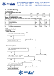
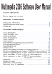
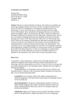
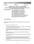
TDMoIP-4E User’s Reference Manual Ver.: 1.2 Modify Date: 2008-2-27 To Users: Thank you for using our products. Before using, please read this Reference Manual carefully, and keep properly. Alarm 1、This product can not be caught in or be affected with damp, for they can make the performance degressive and even broken. 2、Before fixing this product ,please check the model and according to the User’s Reference Manual. Contents CHAPTER1 GENERAL INFORMATION ......................................................................................... 1 1.1 INTRODUCTION .............................................................................................................................. 1 1.2 CHARACTERISTICS ........................................................................................................................ 2 1.3 PARAMETER AND INDEX ................................................................................................................. 3 1.4 WORKING CONDITION ................................................................................................................... 4 1.5 DIMENSIONS ................................................................................................................................... 4 1.6 PACKING ......................................................................................................................................... 4 CHAPTER2 CONFIGURATION ......................................................................................................... 6 2.1 THE FRONT PANEL.......................................................................................................................... 6 2.1.1 Buttons .................................................................................................................................... 6 2.1.2 Indicators ................................................................................................................................ 7 2.2 REAR PANEL ................................................................................................................................... 8 2.2.1 Power supply ........................................................................................................................... 8 2.2.2 E1 interface ............................................................................................................................. 8 2.2.3 Ethernet interface (LAN PORT) .............................................................................................. 9 2.2.4 Consol (network interface RS232) ........................................................................................ 10 2.3 CLOCK MODE................................................................................................................................ 10 CHAPTER3 TROUBLE SHOOTING ............................................................................................... 14 3.1 PWR OFF .................................................................................................................................... 14 3.2 E1 (N) LOS ON ............................................................................................................................ 14 3.3 LNK/ACT OFF ............................................................................................................................. 14 3.4 PKT (N) LOS ON......................................................................................................................... 14 3.5 TWO SIDES’ E1 TERMINAL DEVICE BIT SLIP SERIOUS ................................................................. 15 CHAPTER4 APPLICATION .............................................................................................................. 16 CHAPTER5 NETWORK MANAGEMENT OPERATION ............................................................ 18 5.1 HYPER-TERMINAL’S ATTRIBUTE SETTING................................................................................... 18 5.2 COMMAND SETTING ..................................................................................................................... 18 5.2.1 Parameter definition ............................................................................................................. 18 5.2.2 Main menu............................................................................................................................. 24 5.2.3 Basic settings menu ............................................................................................................... 25 5.2.4 High-grade setting menu ....................................................................................................... 26 5.2.5 Inquiry setting menu .............................................................................................................. 27 5.2.6 Loop setting menu ................................................................................................................. 28 5.2.7 Save settings menu ............................................................................................................... 28 5.2.8 Shift between Chinese/English .............................................................................................. 29 5.3 EXAMPLE OF THE PARAMETER UNDER NORMAL CONDITION ..................................................... 29 -1- Chapter1 General Information 1.1 Introduction TDMoIP-4E is mainly used to transmit voice signal over IP network. It has 1-4 E1 interface, 2 local Ethernet port and 1 uplink Ethernet port. TDMoIP-4E can connect TDM device and user’s Ethernet seamlessly and reliably on the standard low cost wireless or lineate Ethernet/IP configuration, without affecting the voice quantity. Being transparent to the TDM signal, this model assures connecting to physical E1 interface of any device seamlessly, such as PBX, mobile base station, SS7 signaling device and voice mail system. It can be used in the communication system based on E1, such as LAN, WAN, MAN and wireless network. Providing emulation E1 channel through Ethernet, the difficulty is rebuilding timing information of E1 code stream effectively at the exit of network. The special disadvantages of Ethernet itself, such as random packet delay, without effective timing transmit mechanism, transmission error or collision that brings on packet lose, must be conquered. Our company resolves the difficulties above faultlessly through availing ourselves of technical advantage and adapting advanced clock disposal technology. TDMoIP-4E encapsulates the date of E1 code stream to the packet and transmits it to the remote device through Ethernet. This model TDMoIP-4E ------------------------ -2- has two method of encapsulation for optional: Ethernet encapsulation simplicity and UDP/IP protocol encapsulation. The former is suit for the connection of the same Ethernet subnet, because it has high encapsulation efficient especially suited to the occasion of bandwidth intensity, such as interconnection based on the wireless network bridge. But it can’t span router. The latter is suit for the inner net connection of IP net, with the advantage of making use of router or 3-layer switch. But the disadvantage is that the addition IP header needs extra bandwidth. When adapting 128B encapsulation, each E1 channel will take up 500kbps more than Ethernet encapsulation simplicity, with lower transmission efficiency. User can select different encapsulation type based on practical usage occasions. 1.2 Characteristics Transmit framing, non-framing and complex-framing E1 (N*64K)signal Transparently, confirming to ITU-G.703. High transmit efficiency, low transmit delay. Provide 1-4 E1 channels and 2 10/100Base-TX downlink ports with universal RJ45 Ethernet interface, 10M/100M auto-adapt. The length of Ethernet packet can be set, supporting long packet. User can select IP protocol encapsulation or simplicity Ethernet type. TDMoIP-4E ------------------------ -3- Support VLAN setting. Point to point or point to multi-points connections, satisfying different applications. High efficiency transmission, up to 90% bandwidth utility ratio. Support two type interfaces-75Ω and 120Ω-unneed setting. 10/100M Ethernet, full/half duplex auto-adapt, support auto-MDIX. When selecting network adaptation clock, it can resume the original clock accurately through TDM clock resumption mechanism, stable clock, little jitter and small excursion, conforming to ITU-T clock jitter and excursion standard. 1.3 Parameter and index (1) E1 interface Standard: conform to G.703 standard Code rate: 2.048Mbit/s±50ppm Code type: HDB3 Impendence: 75Ω(unbalance)/ 120Ω(balance) Connector: BNC(unbalance)/ RJ45(balance) Jitter tolerance: conform to G.742 and G.823 (2) 10/100Base-T port TDMoIP-4E ------------------------ -4- Rate: Protocol: 10/100M, full/half duplex auto-adapt support IEEE 802.3, IEEE 802.1Q (VLAN) MAC address table: 1024 MAC addresses Physical connector: RJ45, support AUTO-MDIX 1.4 Working condition Voltage: AC180V ~ 260V, DC –48V, DC +24V Power Consumption: ≤5W Working temperature: 0°C~50°C Storage temperature: -40°C~+70°C Relative humidity: 95% No causticity and solvent, dust free and no strong magnetic interference. 1.5 Dimensions 483mm×140mm×44mm 1.6 Packing Inside the box listed the following: TDMoIP-4E 1 BNC connector 4 AC220V power wire (when ordered AC220V) 1 TDMoIP-4E ------------------------ -5- user’s manual 1 TDMoIP-4E ------------------------ -6- Chapter2 Configuration 2.1 The front panel LinkUp DATA2 DATA1 RLOP LLOP Link/Act E1ALos E1BLos E1CLos E1DLos PWD SPD PKTALos PKTBLos PKTCLosPKTDLos Chart 2.1 front panel 2.1.1 Buttons There are four buttons (default is loose) on the front panel; they are as follows from left to right: RLOP: Remote E1 interface loop (inner loop), used to check the IP network connection of the local & remote devices. Chart 2.2 RLOP button function LLOP: Local E1 interface loop (inner loop), used to check if the local device and E1 line is working normally. TDMoIP-4E ------------------------ -7- Chart 2.3 LLOP button function 2.1.2 Indicators There are 16 indicators on the front panel, indicating the working status of local device. Show as table 2.1: Chart 2.1 indicator function Name Status WINK Description Ethernet interface date transmitting or receiving Link/Act OFF No data transmission ON 100M OFF 10M ON A channel E1 signal lost OFF A channel E1 signal normal ON B channel E1 signal lost OFF B channel E1 signal normal ON C channel E1 signal lost OFF C channel E1 signal normal ON D channel E1 signal lost OFF D channel E1 signal normal ON A channel does not receive virtual Ethernet packet OFF A channel reception normal ON B channel not receive virtual Ethernet packet OFF B channel reception normal ON C channel does not receive virtual Ethernet packet OFF C channel reception normal SPD E1Alos E1Blos E1Clos E1Dlos PKTALos PKTBLos PKTCLos TDMoIP-4E ------------------------ -8- ON D channel not receive virtual Ethernet packet OFF D channel reception normal ON Power on OFF Power off PKTDLos PWR OTHER Stand by 2.2 Rear panel E1-D E1-D E1-C E1-B 120 Ω E1-C E1-B E1-A UpLink E1-A OUT OUT OUT OUT IN IN IN IN DATA1 DATA2 Consol Chart 2.4 rear panel 2.2.1 Power supply Support AC220V/DC-48V/DC+24V(for optional when order) AC220V: insert AC220V power supply. DC-48V/DC+24V: without distinguish positive or negative pole (there is auto-detection circuit inner); DC+5V: connect to the power adapter. 2.2.2 E1 interface This model provides two impendence types: 75Ω and120Ω, no need TDMoIP-4E ------------------------ -9- setting, but can’t use them at the same time. 75Ω: the physical interface is BNC connector, RX as input, TX as output. 120Ω: the physical interface is RJ45 port. Pin definition is as chart 2.5: Chart 2.5 interface pin define 2.2.3 Ethernet interface (LAN PORT) There are 2 DATA ports and 1 uplink port on the rear panel, supporting auto-MDIX. Connection is as chart 2.6: Chart 2.6 LAN interface pin definition and the making method TDMoIP-4E ------------------------ - 10 - NOTE: When the line of LAN interface is too long, make sure to make the bipod of receiver signal connect to the same pair of twisted, the bipod of transmitter connects to the same pair of twisted. 2.2.4 Consol (network interface RS232) Pin definition console port is as chart 2.7: 2.7 network interface pin definition and making method 2.3 clock mode As E1 signal transparent transmission device, TDMoIP not only TDMoIP-4E ------------------------ - 11 - transmit the E1 data stream to the receiver, but also rebuild the timing information of E1 signal from the transmitter verily on the receiver with high-quality. Usually between the E1 signal of bidirectional transmission not always have synchronization relationship. In other words, although having the same nominal rate (2048kbps), the signals transmitting in the same E1 channel could have about 100ppm frequency difference. In this condition, the receiver must rebuild timing based on the E1 code stream transmitted from the remote end; this is defined as thorough timing mode. This model that our company produced adapts advanced timing resume technology, the jitter of deferent clock of E1 is small, and the frequency stability is high as well. So it can meet most of applications. For the transmission of date packet through Ethernet or IP has large random, though the timing rebuilding can resume high stability and low jitter clock, long-time excursion is large. This will not influence receiver device’s normal work which adapt hypotaxis timing mode; but for some application, such as adapting switch that using inner clock, it may arose framing storage overflow at the input end which will bring on frame slip. So TDMoIP provides another timing mode-receiver loop timing mode-for optional. In this mode, TDMoIP rebuilding E1 output code stream based on the clock distilling from E1 input signal, absorbing the excursion from network transmission completely by its inner storage. TDMoIP-4E ------------------------ - 12 - Chart 2.8 shows the two timing modes: Chart 2.8 timing mode It is very important for service quality assurance to select suitable clock mode. In practical applications, usually the TDMoIP device connected to the device that uses master clock( such as switch) should be set to loop timing mode. And the device connected to the device that uses slave clock should be set to through timing mode. When two side of devices both use synchronization master clock, for example, the connection of switchers that have independence clock distribute net, two side TDMoIP devices should work in loop timing mode. If two side devices use asynchronous master clock, then the TDMoIP devices should be set to through timing mode, or there will be bit slip. Note: it is usual mistake to let two device connected each other at two end (such as PCM terminal devices) both work in slave clock. Usually transmitting device include TDMoIP do not support this connection mode. When start-up, the locking of clock needs a long time, usually a few TDMoIP-4E ------------------------ - 13 - minutes. It is normal if arose few bit slip or error codes during this time. When connecting as Chart 2.9, the selection of timing mode is shown as table 2.2. Chart 2.9 device interconnection Table2.2 timing mode set principle A side clock B side clock A side B side mode mode TDMoIP TDMoIP timing mode timing mode Master clock Master clock Loop timing Loop timing Remark A, B sides’ clock from the same synchro-network Master clock Master clock Through timing Through A, B sides’ clock are timing independent of each other Master clock Slave clock Loop timing Through timing Slave clock Master clock Through Loop timing timing Slave clock Slave clock Not allowed TDMoIP-4E ------------------------ - 14 - Chapter3 Trouble shooting The follows describe the Common trouble shootings when usage, please contact with us if meet other questions. 3.1 PWR OFF Please check the power supply. 3.2 E1 (n) LOS ON E1(n)LOS ON, indicates the input signal of local E1 port lose. Please follow the steps below for trouble shooting: first check whether the other end E1 terminal device, such as PCM, power off; second, check whether the connection cable and E1 connectors are credibility. For example, E1 line turn off, this case can arose input signal lost. 3.3 Lnk/Act OFF Lnk/Act OFF indicates that 10/100Base-Tx interface not connecting correctly. Check whether the network turn off, output wire of the interface is correct and the computer or other network devices which connected with Lnk/Act work normally. 3.4 PKT (n) LOS ON PKT(n)Los ON, indicates that local E1 does not receive Ethernet TDMoIP-4E ------------------------ - 15 - packet and two end devices can’t communicate with each other. Please follow the below steps for trouble shooting: first, check whether two end devices are in the same Ethernet broadcasting area, check if set the two end’s dualization relationship of MAC address correctly or adopting ARP protocol; second, check whether the MAC address is exclusive, including other network devices; check the Ethernet using ping command; third, check whether bandwidth is sufficient. If two end devices are in different Ethernet segment, then check the default gateway IP address, both sides’ IP address and subnet mask IP address are set correctly; Check if adopting ARP protocol, if there is collision of MAC address or IP address; Check if the bandwidth is sufficient. 3.5 Two sides’ E1 terminal device bit slip serious Check if two sides’ E1 terminal devices that connected to TDMoIP are working in slave clock mode. At least one side device should work in master clock mode. Check the timing mode setting of TDMoIP. If two sides’ E1 devices don’t under synchronization status, TDMoIP’s timing mode should be in through timing mode, but not in loop timing mode. Note: In the first few minutes after power on, it is normal existing bit slip. TDMoIP-4E ------------------------ - 16 - Chapter4 Application TDMoIP-4E can build 1-4 transparent E1 channels on Ethernet or IP network, used to provide real time service of voice and so on, shown as chart 4.1 。 Chart4.1 model network application In the above chart, TDMoIP send 1-4 channel E1 signal through Ethernet (wireless bridge), connecting PBX and network devices and other E1 terminal devices. The two switches located at different areas realize connecting through TDMoIP device’s Ethernet interface. The QoS mechanism of TDMoIP assures E1 signal prior transmit. The typical application of this model is providing E1 channel through wireless bridge. It can connected with wireless bridge of most factories. The transmission bandwidth of many wireless bridge sold at the market are change with the TDMoIP-4E ------------------------ - 17 - Ethernet packet length at present, some bridge induct large packet delay jitter. When use with different bridge, may need to adjust E1 envelopment length and the index of jitter absorb buffer, so that to obtain the best transmission result. TDMoIP-4E ------------------------ - 18 - Chapter5 Network management operation TDMoIP can be set through PC hyper-terminal, using console. 5.1 Hyper-terminal’s attribute setting Set the hyper-terminal as the following protocol: Baud rate: 9600 Date bit: 8 Even-odd check: no Stop bit: 1 Date stream control: none After connecting pc and TDMoIP successfully, press “enter”, operate as the clew below. 5.2 Command setting 5.2.1 Parameter definition The parameters of TDMoIP that can be set by user are as table 5.1: Table5.1 TDMoIP parameter table Parameter Abstract illumination prohibit:directly set the aim station MAC address Whether use ARP protocol through monitor; TDMoIP-4E ------------------------ - 19 - prohibit:obtain the aim station MAC address through ARP protocol; yes:adopt IP encapsulation the IP of fountain and aim address need setting, can through router, Whether encapsulation IP bandwidth efficient is low a little; nameplate no:not adopt IP encapsulation,bandwidth efficient is high,can not through router; yes:add four bit before Ethernet framing style bit,the first two bit is VLAN 0x8100,the latter two bit is Whether encapsulation VLAN mark high parameter VLAN ID,suit for the net transmit of support VLAN priority ,assured QoS of E1; no:no VLAN label;suit for the net transmit of not support VLAN priority Every Ethernet packet encapsulation E1 date,can set the bit random among 64-2048,the longer of the packet,the more E1 date, the little spending scale , E1date packet length bandwidth bit,the higher efficient,but the bigger delay time。Vice versa。Note: for the exchange and router have command to the packet length, so not too long, not more then1518. Through timing:E1 timing comes from remote input E1 code stream; Clock setting mode loop timing:E1 timing comes from local input E1 code stream; Set upload Ethernet interface full duplex total bandwidth,in order to work normal the actual Upload limit bandwidth transmission periodic line bandwidth must higher than the setting value。Leave factor value is99Mbps Jitter absorb buffer When use with the periodic line of bigger packet TDMoIP-4E ------------------------ - 20 - jitter,used to buffer receiver end come packet,can eliminate packet jitter arose by middle periodic line 。value range:1~64 Ethernet MAC address of this device;Leave factor Local MAC address value :00:00:00:A1:A2:A3 Ethernet MAC address of remote device,valid when Default remote MAC address not using ARP protocol; IP address of this device;Leave factor Local IP address value :192.168.1.209 IP address of remote device;Leave factor value Remote IP address 192.168.1.210 Used to verdict whether the source and aim are in the same subnet, let source with aim IP address and subnet mask digitize logic multiply,the same result subnet mask indicate that source and aim are in the same subnet, otherwise the oppose,need default gateway router; Leave factor value :255.255.0.0 When the source and aim are not in the same subnet, need to set gateway IP address,gateway address and default gateway IP address source device are in the same subnet。Seek address through ARP protocol;Leave factor value 192.168.1.101 When the source and aim are in the same subnet, needn’t to encapsulate IP nameplate,Ethernet frame Custom MAC frame type style bit ,source and aim custom must be the same。 NOTE:this type don’t collide with the other defined type in the net;Leave factor value :0x0505 VLAN TAG control In order to meet some QoS,can set VLAN mark。 TDMoIP-4E ------------------------ - 21 - information When use with VLAN,there are four bit VLAN mark on the front of the original Ethernet frame type bit, the first two is VLAN type bit 0x0002,the latter two is VLAN TAG control information,can define by the user,please read VLAN manual. When Encapsulate IP nameplate,first encapsulate E1 date to UDP date packet,then add IP nameplate,set UDP application interface base on practical need,in order to receive correctly,the setting UDP interface UDP port of the local and remote must the same ,not colliding with other appliance have exist ;Leave factor value 1010 Note: 1. The illuminate of the uplink limit bandwidth. For the bandwidth limit of the actual transmission of periodic line; the actual output rate of uplink should be match with it, It means that if the transmission periodic line bandwidth is smaller than the actual output rate of the uplink, it can arose some questions such as mistake code. So we set the parameter of uplink limit bandwidth to fit the actual periodic line bandwidth limitation. When the setting value of uplink bigger than the actual E1 input rate, the dispatch is the local Ethernet rate. The setting value of uplink smaller then the actual E1 input rate, Ethernet input rate is 0. For example: transmission periodic line can provide 6M bidirectional bandwidth, if use TDMoIP-4E ------------------------ - 22 - two channel E1, then the local Ethernet uplink setting value should smaller than 6M. If bigger than 6M, then the actual transmission rate of uplink may bigger than the bandwidth of transmission periodic line, this may arose some question such as mistake code. In addition, the Ethernet bandwidth is giver as the halt duplex, for example, 10M half duplex Ethernet channel is the same as 5M full duplex. 2. E1 bandwidth self-adapt, based on whether E1 inset or not, only E1 end signal don’t lost, system can distribute bandwidth to it. When E1 interface is free, system will release bandwidth automatism, this be used to local Ethernet inset. 3. The E1 signal channel of TDMoIP can works at through timing and loop timing, as chart2.8. Default work state should be through timing. note, timing mode apply two E1 interface at the same time .when at the through timing state, two channel E1 adapt themselves resume clock coming from the remote signal separately; when at the looping timing state, two channel E1 adapt themselves distill clock coming from local interface input signal. 4. Every end device moving at the Ethernet need one MAC address which are alone、stable、12 bit hexadecimal numeral indicator, such as 80:80:80:80:80:80,can realize the communication with other device. The TDMoIP-4E ------------------------ - 23 - Ethernet uplink of TDMoIP device has a MAC address also, namely MAC addresses, and users set it themselves. When don’t adapt APR protocol, in order to realize dual communication, every end TDMoIP set MAN address of remote device, namely remote address. When both local MAC address are the remote address of the opposite, two end devices can communication. Adapt ARP protocol, MAC of opposite device or default gateway device automatic obtain through negotiation, don’t need to set remote MAC address specially, but need to set IP address of both end. Note: All device’s MAC address of Ethernet broadcast field must alone, or else arose address collision! 5.In order to enhance transmission service quality of E1 date, according to Ethernet providing transmission whether provide IEEE802.1Q and 802.1p standard , can set TDMoIP if add VLAN tag packet prior grade when packing according to this standard. Standard packet according to 802.1Q/802.1p,envelop spending big a little (every Ethernet packet add 4bit), but can transmit as the senior prior grade. But for the standard net not support 802.1p isn’t have the actual mean, and can add the transmission bandwidth spending which isn’t need, so set the parameter of TAG into NO. Realize the every kind of parameter setting through follow section menu TDMoIP-4E ------------------------ - 24 - command. 5.2.2 Main menu Select (0), quit from the setting menu. Select(1),enter basic setting menu. Select (2) enter hi-grade setting menu. Select (3) enter inquiry the current parameter settings value. Select (4) save settings, if quit before save the settings, the amend value is not save. Select (5) E1looping settings. Select (6) shift between Chinese/English。 High-grade setting is mainly to set frame head parameter ,about MAC address、IP address、type、 interface and so on, these parameter is not always effect in any application, for example ,when don’t encapsulate IP nob, IP address and UDP interface is inefficacy; When open ARP protocol, MAC address of the aim station is inefficacy. The basic settings decide whether the hi-grade settings are usage or not. TDMoIP-4E ------------------------ - 25 - 5.2.3 Basic settings menu Every parameter setting of basic setting menu is as chart5.1 below: Chart 5.1 every parameter select (value)and the meaning option number parameter illumination (value) First encapsulate date into UDP/IP date 1 (1) packet , then encapsulate it into Ethernet framing date area. Use IP protocol encapsulate E1 date into Ethernet framing 0 date area directly before Ethernet framing type have VLAN 1 label (2) Use VLAN before Ethernet framing type have not VLAN 0 labels 1 (3) Use ARP protocol Obtain aim station MAC ground Don’t use ARP protocol,appoint aim station 0 directly. 64-2048can random set 。note: for changer、 Ethernet packet (4) 64-2048 router have request to the packer length, not size too long ,small than 1518 at best. TDMoIP-4E ------------------------ - 26 - Through timing: resume E1 clock from 1 Ethernet code stream (5) Clock mode Loop timing: clock output E1 is the clock 0 distill from local input E1 signal directly Can random set, used to absorb periodic line packet jitter ,N=4—64。The bigger of the Elasticity buffer (6) 4-64 buffer ,the bigger of the absorb packet jitter, depth but the delay time is longer. The smallest value of the full duplex provide Uplink Ethernet (7) by uplink Ethernet transmission channel, 1-99 when the actual bandwidth is lower than the bandwidth value,E1 transmission is abnormal. 5.2.4 High-grade setting menu Every parameter setting of hi-grade setting menu is as chart5.2 below: Chart 5.2 hi-grade parameter select table parameter illumination Local MAC address Local MAC address,6 bits,hexadecimal input , “:”as the TDMoIP-4E ------------------------ - 27 - separator code between the bits Remote MAC destination station MAC address,6 bits,hexadecimal input, address “:”as the separator code between the bits,when prohibit use ARP protocol,this address as the aim address of Ethernet framing; When use ARP protocol, this address obtain automatically. Local IP address Source station IP address,namely local IP address,4 bits,point hexadecimal input,use when application ARP protocol or encapsulation IP nameplate. Remote IP address IP destination station IP address,4 bits,point hexadecimal input,use when application ARP protocol or encapsulation IP nameplate. Subnet mask Subnet mask, used to judge whether the source station and destination station are in the same subnet or not. gateway IP default gateway, in application of IP, if the source station and destination station are not in the same subnet, the Ethernet framing of source station send to gateway, then, gateway send it to the destination station. Ethernet frame Custom Ethernet type, non IP application, Ethernet framing mode mode is the custom type. It needn’t to set except collide with the other device of the net. VLAN TAG when apply VLAN ,VLAN value. UDP port When apply IP,destination port value of UDP date nameplate。 It needn’t to set except collide with the other device of the net. 5.2.5 Inquiry setting menu Select (3) on the main menu to show current setting, screen will TDMoIP-4E ------------------------ - 28 - show the current settings value of all parameter, and quit to the main menu to remand or save the current setting. 5.2.6 Loop setting menu Input select as the clew, don’t save the setting value,E1 of local and remote are not loop on the default condition, when need to test, E1 of local and remote should be on the state of loop ,after testing, cancel loop at best. 5.2.7 Save settings menu Select (4) on the main menu to save the settings, any parameter modification through monitor interface, save to the flash through save parameter command, it will call the modification parameter automatically when nest boot-strap. TDMoIP-4E ------------------------ - 29 - 5.2.8 Shift between Chinese/English Select (6) on the main menu to shift between Chinese/English, shift to English menu when in the Chinese menu state currently, shift to Chinese menu when in the English menu currently. It will save the current Chinese/English state automatically when shifting. 5.3 Example of the parameter under normal condition Parameters Local configures Remote configures Use 1P set 1, used 1,used Use VLAN set 0, unused 0, unused Use ARP set 1,used 1,used Timing set 0, through 0,through Package size set 1024 1024 Jitter buffer set 32 32 Uplink bandwidth set 99 99 Local MAC set 00:00:00:A1:A2:A3 00:00:00:B1:B2:B3 Local IP set 192.168.1.209 192.168.1.210 Remote MAC set 00:00:00:B1:B2:B3 00:00:00:A1:A2:A3 Remote IP set 192.168.1.210 192.168.1.209 TDMoIP-4E ------------------------ - 30 - Subnet mast set 255.255.0.0 255.255.0.0 Gateway IP set 192.168.1.101 192.168.1.101 ETH frame type set 0505 0505 VLAN TAG set 0002 0002 UDP port set 1010 1010 !!!Note: Before checking the parameters, you’d best read current running parameter at first. TDMoIP-4E ------------------------