1
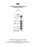
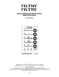
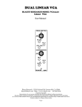
VCA
BLACET RESEARCH MODEL VCA2200
Quad Voltage Controlled Amplifier/Mixer Module
User Manual
Blacet Research 15210 Orchard Rd Guerneville CA 95446
[email protected] http://www.blacet.com 707-869-9164
Contents Copyright.
Reproduction by any means including the Internet prohibited without permission.
This document contains proprietary and trade secret information of Blacet Research and is provided
as a service to the module owner. Any unauthorized duplication or transferral may violate trade secret laws.
Contents subject to change without notice.
Page 1
Introduction
The VCA2200 is a versatile quad voltage controlled amplifier module with an exponential response curve. A high
quality SSM2164 quad VCA IC is used in this unit for lowest noise and distortion.
The module is set up as a four input mixer with a VCA on each input. A Bias pot normals a CV to each VCA unless
a plug is inserted into the CV input for that channel. The mid position of the Bias pot has a detent which is
calibrated for unity gain through the VCAs with the Mix pots turned fully CW. (Channel D has 10X gain).
Channels A, B and C are connected to the ABC(D) Output, with Channel D being normalled unless a plug is
inserted into the D Out.
Channel D can thus be used as a separate VCA. It also has up to 10X gain for use with low level signals.
This VCA is suitable for a variety of tasks, including straight mixing, VC mixing, stereo panning, fading, distortion,
and external signal amplification.
Input A
Mix Level A
Input B
Mix Level B
Attenuation Range
Input C
Mix Level C
Input D
Mix Level D
(Up to 10X Gain)
Mix Output
(D normalled unless
plug is inserted in D
Out)
Mixer Bias
(Center=1:1 Gain)
(CW from center=overdrive)
D Output
CV Inputs: A thru D
(Inserting plug
overrides normalled
Bias CV)
Page 2
Controls and Operation
A voltage controlled amplifier is a pretty simple thing.
VCA
IN
OUT
CV
Actually, the “amplifier” bit is a misnomer because you don’t really amplify anything. You typically get out only
what you put in (unity gain) at maximum control voltage. (The 2200 does have one channel with a 10X gain stage
preceding the VCA.) So, a better name for this device is “Voltage Controlled Attenuator” (still a VCA!).
Here’s what the 2200 looks like inside:
A IN
A
CV
B IN
B
ABC(D) OUT
CV
C IN
C
CV
D IN
D
D OUT
CV
BIAS
The arrows indicate the normalled connections. The Mix pot on each input is not shown.
With no external CV, we have a three or four input mixer with the Bias pot acting as the master volume (or
distortion) control. Add external CV to any input as needed. Since “D” can be completely separate we could also
do a three input mixer with a master VCA controlled by an ADSR:
A IN
A
CV
ABC(D) OUT
B IN
B
D
CV
C IN
D IN
CV
C
ADSR
CV
BIAS
Page 3
D OUT
Another use for VCA “D” takes advantage of it’s 10X gain. External signals from keyboards, etc. can be brought up
to modular synth levels for use with the Final Filtre, Time Machine, Mini Wave, etc.
Stereo panning is easy to do with the addition of the Blacet EG1 VC ADSR module since it has an inverted output
available. Use a multiple or splitter cord to run the audio to the two inputs. You can use A, B or C for the left
output.
A IN
A
CV
ABC(D) OUT
B
L
Audio In
C
EG1
D OUT
D IN
D
Inv
R
CV
To fade between two inputs use the connection below. You can use A, B, or C.
A IN
Audio In
A
CV
B IN
Audio In
ABC(D) OUT
B
CV
EG1
Inv
C
D OUT
D
Since there are uncommitted VCAs in both fading and panning, extra processing can be added as required.
CV mixing: The 2200 is DC coupled so that control voltages can be mixed as well as audio signals. You will
probably find that using the “75 dB” setting of the toggle switch to be the most useful for this application.
CV Range: The 2200 is set up for 0-10V CV. Negative CVs will have no effect.
75dB/100dB Switch: Try using 75dB for mixing CVs and 75dB or 100dB for audio signals.
Power Input Jack J11: A source of regulated +/-15Vdc power must be supplied to this PCB jack to run the module.
Note the current requirements in the “Specifications” section.
Connections to this jack should be made only when the power supply is OFF and the connector must be
positioned correctly on the pins.
As using the wrong supply can cause damage to the unit, please contact us if you have any questions! Do not
attempt to use “wall warts” to power the module.
Page 4
Specifications
Front Panel Size: 5.25 x 3" W
Module Depth: 6”
Input/Output Jacks: 3.5 mm (1/8”)
Amplitude Voltage Control: exponential; 100mV/dB.
Frequency Range: 0 to 20 KHz
CV Range: 0-10V
Output Level: +/-13.5V max
Power: +/-15 Vdc @+29/-29 mA
Calibration
Place the “Bias” front panel pot in the center (detent) position. Set RT1 to read 10.0V at TP1.
Troubleshooting, Repair, Warranty
If you encounter problems that you can’t solve, contact us, preferably via e-mail with a description of the problem.
Let us know what does and does not work. We can then help you get your module working. We can fix modules for
a minimum fee of $25.
The parts contained in this unit have been carefully selected and tested. They are guaranteed for 90 days from the
date of purchase. If you believe that you have a defective part (or if you have a part missing), contact us so we can
provide you with a replacement or repair.
Options
The normal control voltage range of the VCAs is 0-10V. This can be changed to 0-5V by doing the following:
Change RA (R17, 18, 19, 20) to 66.5K (four places).
Cut the RB traces (solder side of PCB) and install four 100K 1% resistors (standing up).
Change R11 to 49.9K
Change R7 to 82K.
Adjust RT1 for 5.0V (See “Calibration”.)
Channel D has 10X gain. To make this 1X, replace R8 with a 100K 5% resistor.
Page 5
J1
5.5”
4X
2.0
J2
2.0
S1
COM
J3
1.5 3X
32 1
2.0
J4
2.0
4.8
J6
3.8
J5
3.8
5.5
6.0
6.0
J10
1.5
1.5
1.5
J9
J8
J7
1.5
2.0
2.0
2.5
2.5
Page 6