1
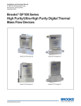
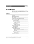
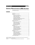
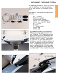
INSTALLATION GUIDE
SH50-50 SHIELDED CABLE
This guide describes how to use the SH50-50 shielded cable to connect
a National Instruments data acquisition (DAQ) or Motion Control device
to accessories and terminal blocks.
Introduction
The SH50-50 shielded cable has a 50-pin female connector with a spade
terminal grounding strap on one end and a 50-pin female connector with
a ring terminal grounding strap on the other end. The connectors are wired
pin-to-pin with a 25 twisted pair shielded cable.
The SH50-50 cable kit also includes a 3 in. ribbon cable and replacement
brackets for your 50-pin AT board or NB board bracket. You can use the
brackets to modify your 50-pin board so that you can connect it to an
accessory via the SH50-50 cable.
What You Need to Get Started
To set up and use your cable, you will need the following items:
❑ SH50-50 shielded cable
❑ SH50-50 Shielded Cable Installation Guide
❑ A compatible National Instruments device
❑ Number 1 Phillips-head screwdriver
❑ 3 in. 50-to-50-pin ribbon cable (included in kit)
❑ Replacement brackets with spade terminals (NB and AT)
(included in kit)
National Instruments™, NI™, and ni.com™ are trademarks of National Instruments Corporation. Product and company names mentioned herein are
trademarks or trade names of their respective companies.
322023B-01
Copyright © 1998, 2001 National Instruments Corp. All rights reserved.
September 2001
Replacing the Bracket
Before you install the SH50-50, you must replace the bracket on your board
with the appropriate bracket from the SH50-50 kit, unless your board
already has a bracket with a spade contact, as shown in Figure 4. If your
board has a bracket with a spade contact, read the Installing the Cable
section.
Use the following steps to replace the brackets on your board:
1.
Turn off the power to your computer.
2.
Remove your board from your computer.
3.
Remove the two screws that attach the bracket to the board.
4.
Remove the bracket from the board. See Figure 1 for NB board bracket
removal or Figure 2 for AT board bracket removal.
Bracket
NB Board
Figure 1. Removing the Bracket from an NB Board
SH50-50 Shielded Cable Installation Guide
2
ni.com
Bracket
AT Board
Figure 2. Removing the Bracket from an AT Board
5.
The 50-pin I/O connector on your board may have small plastic
key inserts installed for mating with military polarized connectors.
Because these keys are incompatible with the 50-pin connector on
the SH50-50 cable, you must remove them. The SH50-50 connector
has a center polarization bump that prevents you from inserting the
connector upside down.
To remove the key inserts, use a thin probe such as a pencil or a pen tip
to gently press down on the release tab in the center of the key insert,
as shown in Figure 3. Then use the probe to lift up the back end of the
key insert and slide the insert off the connector.
© National Instruments Corporation
3
SH50-50 Shielded Cable Installation Guide
DAQ Board
Figure 3. Removing the Key Inserts
6.
Identify the appropriate replacement bracket for your board from your
SH50-50 kit. The bracket that you use should look like the one you
remove, except that the new one has an extra tab that mates with the
grounding strap on the SH50-50 cable assembly.
7.
Install the new bracket by aligning the bracket with the holes in your
board and attach the two mounting screws.
Now you are ready to connect the SH50-50 shielded cable to a 50-pin board
and accessory.
SH50-50 Shielded Cable Installation Guide
4
ni.com
Installing the Cable
Figure 4 illustrates how to connect the SH50-50 shielded cable and the 3 in.
ribbon cable to a 50-pin board and a 50-pin accessory.
1
2
3
Step 4
Step 2
Step 3
6
7
1
2
3
4
5
Spade Contact
Grounding Strap with End Lug
Grounding Strap with Eyelet
50-Pin Accessory
5
6
7
4
3 in. Ribbon Cable
SH50-50 Shielded Cable
50-Pin Board
Figure 4. Connecting to a 50-Pin Board
Follow the instructions below to install the SH50-50 cable to a 50-pin board
and accessory:
1.
Install your board in a slot in your computer, following the instructions
in your board user manual.
2.
Connect the 50-pin connector of the SH50-50 cable with the spade
terminal grounding strap to the board I/O connector. Slide the spade
terminal onto the spade contact of the bracket, as shown in Figure 4.
3.
Connect the 50-pin connector with the ring terminal grounding strap
to your accessory. Attach the ring terminal to any available grounding
screw on your accessory.
4.
To improve flexibility, the 3 in. ribbon cable extender may be used at
the accessory end of the SH50-50.
© National Instruments Corporation
5
SH50-50 Shielded Cable Installation Guide