1
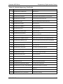
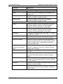
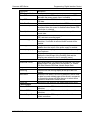
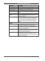
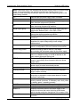
Sorensen ASD Series Programming: Digital Interface Control Table 4-4. Write Registers Address Name IQ Content Notes 0 Command binary See Command description below. 1, 2 Vsetpoint_HI/LO IQ15 / FP Output voltage setpoint. 1.0 = nominal voltage (60V / 40V). 2, 3 3, 4 Isetpoint_HI/LO IQ15 / FP Output current setpoint. 1.0 = nominal current of one module (167A / 250A). 2, 3 5, 6 Psetpoint_HI/LO IQ15 / FP Output power (or process) setpoint. 1.0 = nominal power of one module (10020W / 10000W). 2, 3 7, 8 Module_Vout_peak_HI/LO IQ15 / FP Overvoltage protection threshold. 1.0 = nominal voltage (60V / 40V). 2. 3 9, 10 Zoutput_ Max_HI/LO IQ24 / FP Output impedance max limit. 1.0 = (nominal voltage / nominal current) of one module (0.3593 / 0.1600). 2, 3 11, 12 Zoutput_ Min_HI/LO IQ24/ FP Output impedance min limit. 1.0 = (nominal voltage / nominal current) of one module (0.3593 / 0.1600). 2, 3 13, 14 Zoutput_ ROC_Pos_HI/LO IQ20 / FP Output impedance rate-of-chance max limit. Percent of change per second. 2, 3 15, 16 Zoutput_ ROC_Neg_HI/LO IQ20 / FP Output impedance rate-of-chance min limit. Percent of change per second. 2, 3 17, 18 Fault_Shutdown_Config_HI/LO binary All bits that are “1” will cause the corresponding fault bit to generate a shutdown the unit. 3, 4 19, 20 Zcable_Max_HI/LO IQ24 / FP Cable impedance max limit. 1.0 = (nominal voltage / nominal current) of one module (0.3593 / 0.1600). 2, 3 21, 22 Vdrop_Cable_Max_HI/LO IQ15 / FP Cable voltage drop max limit. 1.0 = nominal voltage (60V / 40V). 2, 3 23, 24 Zmonitor_Imin_HI/LO IQ15 / FP Impedance monitor minimum required current. 1.0 = (nominal voltage / nominal current) of one module (0.3593 / 0.1600). 3 25, 26 Zalpha_HI/LO IQ24 / FP Alpha coefficient of the low pass filter for all impedance calculations. Normalized (0 to 0.9999). 3 27 Save_Defaults binary 0x1234 stores current state as default, 0x5678 restores saved default, 0x9ABC restores factory defaults. 28 Query_Module binary Used to query module data, in combination with Read registers 29, 30 (Query_Module_Info). 29 Expected_Modules Int16 If non-zero a fault will be generated when existing modules does not match this value. See user guide for more details. 30 FDR_Period Int16 31, 32 Vsetpoint_SRL_HI/LO IQ15 / FP 33, 34 Isetpoint_SRL_HI/LO IQ15 / FP 35, 36 monitor_alpha_HI/LO IQ24 / FP See FDR_Period description below for more information. Voltage setpoint slew-rate-limit. 1.0 = nominal voltage (60V / 40V) per ms voltage setpoint rate-of-change limit. Current setpoint slew-rate-limit. 1.0 = nominal current of one module (167A / 250A) per ms current setpoint rate-of-change limit. Alpha coefficient of the low pass filter for the monitor readbacks. Normalized (0 to 0.9999). Used for impedance calculation. If setpoints change more than this value the impedance measurement is considered not valid. Percent per ms. Used for impedance calculation. Time delay after the impedance calculation is considered valid again. 1 is equivalent to 8 ms of delay 37, 37 max_delta_setpoint_HI/LO IQ15 / FP 39 Z_delay Int16 40 Modbus_timeout_period Int16 Used with Modbus timeout feature. 1 is equivalent to 8 ms of delay 41, 42 activation_code_HI/LO Int32 Code to unlock the digital interface. A value of all ones ( 4294967295) will lock it. The correct unlock code is based on an encryption algorithm and the Master Controller serial number. M551177-01 Rev A 2, 3 2, 3 2, 3 2, 3 3 4-13