1
Timing Constraints
User Guide
[Guide Subtitle]
[optional]
UG612 (v 13.2) July 6, 2011 [optional]
Xilinx is disclosing this user guide, manual, release note, and/or specification (the "Documentation") to you solely for use in the development
of designs to operate with Xilinx hardware devices. You may not reproduce, distribute, republish, download, display, post, or transmit the
Documentation in any form or by any means including, but not limited to, electronic, mechanical, photocopying, recording, or otherwise,
without the prior written consent of Xilinx. Xilinx expressly disclaims any liability arising out of your use of the Documentation. Xilinx reserves
the right, at its sole discretion, to change the Documentation without notice at any time. Xilinx assumes no obligation to correct any errors
contained in the Documentation, or to advise you of any corrections or updates. Xilinx expressly disclaims any liability in connection with
technical support or assistance that may be provided to you in connection with the Information.
THE DOCUMENTATION IS DISCLOSED TO YOU “AS-IS” WITH NO WARRANTY OF ANY KIND. XILINX MAKES NO OTHER
WARRANTIES, WHETHER EXPRESS, IMPLIED, OR STATUTORY, REGARDING THE DOCUMENTATION, INCLUDING ANY
WARRANTIES OF MERCHANTABILITY, FITNESS FOR A PARTICULAR PURPOSE, OR NONINFRINGEMENT OF THIRD-PARTY
RIGHTS. IN NO EVENT WILL XILINX BE LIABLE FOR ANY CONSEQUENTIAL, INDIRECT, EXEMPLARY, SPECIAL, OR INCIDENTAL
DAMAGES, INCLUDING ANY LOSS OF DATA OR LOST PROFITS, ARISING FROM YOUR USE OF THE DOCUMENTATION.
© 2011 Xilinx, Inc. XILINX, the Xilinx logo, Virtex, Spartan, ISE, and other designated brands included herein are trademarks of Xilinx in the
United States and other countries. All other trademarks are the property of their respective owners.
Revision History
The following table shows the revision history for this document.
Date
Version
03/01/2011
13.1
07/06/2011
13.2
TIming Constraints User Guide
Added Chapter 7, Timing Closure.
•
Added content on:
•
Minimum Period
•
Multi-Corner, Multi-Node Timing
Analysis
•
SYSTEM_JITTER
•
Reg_sr_r and Reg_sr_o
•
Changed SDC to .sdc.
•
Added warning that the number of timespecs
impacts runtime.
•
Expanded information in several places in
Chapter 7, Timing Closure.
www.xilinx.com
UG612 (v 13.2) July 6, 2011
Table of Contents
Revision History . . . . . . . . . . . . . . . . . . . . . . . . . . . . . . . . . . . . . . . . . . . . . . . . . . . . . . . . . . . . . 2
Chapter 1: Introduction
Chapter 2: Timing Constraint Methodology
Basic Constraints Methodology . . . . . . . . . . . . . . . . . . . . . . . . . . . . . . . . . . . . . . . . . . . . . . . 8
Input Timing Constraints . . . . . . . . . . . . . . . . . . . . . . . . . . . . . . . . . . . . . . . . . . . . . . . . . . . . 9
Register-To-Register Timing Constraints . . . . . . . . . . . . . . . . . . . . . . . . . . . . . . . . . . . . 13
Output Timing Constraints . . . . . . . . . . . . . . . . . . . . . . . . . . . . . . . . . . . . . . . . . . . . . . . . . . 17
Timing Exceptions . . . . . . . . . . . . . . . . . . . . . . . . . . . . . . . . . . . . . . . . . . . . . . . . . . . . . . . . . . 21
Chapter 3: Timing Constraint Principles
Constraint System . . . . . . . . . . . . . . . . . . . . . . . . . . . . . . . . . . . . . . . . . . . . . . . . . . . . . . . . . . .
Constraint Priorities . . . . . . . . . . . . . . . . . . . . . . . . . . . . . . . . . . . . . . . . . . . . . . . . . . . . . . . . .
Timing Constraints . . . . . . . . . . . . . . . . . . . . . . . . . . . . . . . . . . . . . . . . . . . . . . . . . . . . . . . . .
Timing Constraint Syntax . . . . . . . . . . . . . . . . . . . . . . . . . . . . . . . . . . . . . . . . . . . . . . . . . . .
Creating Timing Constraints . . . . . . . . . . . . . . . . . . . . . . . . . . . . . . . . . . . . . . . . . . . . . . . .
25
43
45
61
61
Chapter 4: Specifying Timing Constraints in XST
Specifying Timing Constraints in HDL or XCF . . . . . . . . . . . . . . . . . . . . . . . . . . . . . . 63
XST Timing Constraints . . . . . . . . . . . . . . . . . . . . . . . . . . . . . . . . . . . . . . . . . . . . . . . . . . . . . 65
Chapter 5: Specifying Timing Constraints in Synplify
Synplify Timing Constraints . . . . . . . . . . . . . . . . . . . . . . . . . . . . . . . . . . . . . . . . . . . . . . . . 79
Specifying Timing Constraints in HDL . . . . . . . . . . . . . . . . . . . . . . . . . . . . . . . . . . . . . . 81
Specifying Timing Constraints in an .sdc File (Tcl). . . . . . . . . . . . . . . . . . . . . . . . . . . 94
Specifying Timing Constraints in a SCOPE Spreadsheet . . . . . . . . . . . . . . . . . . . . 109
Forward Annotation . . . . . . . . . . . . . . . . . . . . . . . . . . . . . . . . . . . . . . . . . . . . . . . . . . . . . . . . 109
Chapter 6: Timing Constraint Analysis
Timing Analyzer . . . . . . . . . . . . . . . . . . . . . . . . . . . . . . . . . . . . . . . . . . . . . . . . . . . . . . . . . . .
Timing Report . . . . . . . . . . . . . . . . . . . . . . . . . . . . . . . . . . . . . . . . . . . . . . . . . . . . . . . . . . . . .
Multi-Corner, Multi-Node Timing Analysis . . . . . . . . . . . . . . . . . . . . . . . . . . . . . . . .
PERIOD Constraints . . . . . . . . . . . . . . . . . . . . . . . . . . . . . . . . . . . . . . . . . . . . . . . . . . . . . . .
FROM:TO (Multi-Cycle) Constraints . . . . . . . . . . . . . . . . . . . . . . . . . . . . . . . . . . . . . . .
OFFSET IN Constraints . . . . . . . . . . . . . . . . . . . . . . . . . . . . . . . . . . . . . . . . . . . . . . . . . . . .
OFFSET OUT Constraints . . . . . . . . . . . . . . . . . . . . . . . . . . . . . . . . . . . . . . . . . . . . . . . . . .
Clock Skew . . . . . . . . . . . . . . . . . . . . . . . . . . . . . . . . . . . . . . . . . . . . . . . . . . . . . . . . . . . . . . . .
TIming Constraints User Guide
UG612 (v 13.2) July 6, 2011
www.xilinx.com
113
113
114
115
124
127
136
143
3
Clock Uncertainty . . . . . . . . . . . . . . . . . . . . . . . . . . . . . . . . . . . . . . . . . . . . . . . . . . . . . . . . . . 145
Asynchronous Reset Paths . . . . . . . . . . . . . . . . . . . . . . . . . . . . . . . . . . . . . . . . . . . . . . . . . 147
Chapter 7: Timing Closure
Achieving Timing Closure . . . . . . . . . . . . . . . . . . . . . . . . . . . . . . . . . . . . . . . . . . . . . . . . .
Steps to Achieving Timing Closure . . . . . . . . . . . . . . . . . . . . . . . . . . . . . . . . . . . . . . . . .
Improving Timing Failures . . . . . . . . . . . . . . . . . . . . . . . . . . . . . . . . . . . . . . . . . . . . . . . . .
Timing Failure Design Scenarios . . . . . . . . . . . . . . . . . . . . . . . . . . . . . . . . . . . . . . . . . . .
Cross Probing . . . . . . . . . . . . . . . . . . . . . . . . . . . . . . . . . . . . . . . . . . . . . . . . . . . . . . . . . . . . . .
149
151
170
172
184
Appendix A: Additional Resources
4
www.xilinx.com
TIming Constraints User Guide
UG612 (v 13.2) July 6, 2011
Chapter 1
Introduction
The Timing Constraints User Guide (UG612) addresses timing closure in high-performance
applications. The Guide is designed for all FPGA designers, from beginners to advanced.
The high performance of today's Xilinx® devices can overcome the speed limitations of
other technologies and older devices. Designs that formerly only fit or ran at high clock
frequencies in an ASIC device are finding their way into Xilinx FPGA devices. In addition,
designers must have a proven methodology for obtaining their performance objectives.
This Guide discusses:
•
The fundamentals of timing constraints, including:
•
PERIOD Constraints
•
OFFSET Constraints
•
FROM:TO (Multi-Cycle) Constraints
•
The ability to group elements and provided a better understanding of the constraint
system software
•
Information about the analysis of the basic constraints, with clock skew and clock
uncertainty
•
Specifying timing constraints in the Xilinx Synthesis Technology (XST)
•
Specifying timing constraints in Synplify
TIming Constraints User Guide
UG612 (v 13.2) July 6, 2011
www.xilinx.com
5
Chapter 1: Introduction
6
www.xilinx.com
TIming Constraints User Guide
UG612 (v 13.2) July 6, 2011
Chapter 2
Timing Constraint Methodology
You must have a proven methodology in order to meet your design objectives. This
chapter outlines the process to:
•
Understand the design requirements
•
Constrain the design to meet these requirements
Before starting a design, you must understand:
•
The performance requirements of the system
•
The features of the target device
This knowledge allows you to use proper coding techniques utilizing the features of the
device to give the best performance.
The FPGA device requirements depend on the system and the upstream and downstream
devices. Once the interfaces to the FPGA device are known, the internal requirements can
be outlined. How to meet these requirements depends on the device and its features.
You should understand:
•
The device clocking structure
•
RAM and DSP blocks
•
Any hard IP contained within the device
For more information, see the device user guide.
Timing constraints communicate all design requirements to the implementation tools. This
also implies that all paths are covered by the appropriate constraint. This chapter provides
general guidelines that explain the strategy for identifying and constraining the most
common timing paths in FPGA devices as efficiently as possible.
TIming Constraints User Guide
UG612 (v 13.2) July 6, 2011
www.xilinx.com
7
Chapter 2: Timing Constraint Methodology
Basic Constraints Methodology
Timing requirements fall into into several global categories depending on the type of path
to be covered.
The most common types of path categories include:
•
Input paths
•
Synchronous element to synchronous element paths
•
Path specific exceptions
•
Output Paths
A Xilinx® timing constraint is associated with each of these global constraint types. The
most efficient way to specify these constraints is to begin with global constraints and add
path specific exceptions as needed. In many cases, only the global constraints are required.
The FPGA device implementation tools are driven by the specified timing requirements.
They assign device resources and expend the appropriate amount of effort necessary to
ensure the timing requirements are met. However, when a requirement is over-constrained
- or specified as a value greater than the design requirement - the effort spent by the tools
to meet this constraint increases significantly. This extra effort results in increased memory
use and tool runtime.
More importantly, over-constraint can result in loss of performance, not only for the
constraint in question, but for other constraints as well. For this reason, Xilinx recommends
that you specify the constraint values using the actual design requirements.
Xilinx recommends that you always comment the constraints file. This allows other
designers to understand why each constraint is used.
Include in your comments:
•
Source of the constraint
•
Whether the PERIOD constraint is based on an external clock
This Guide uses XCF constraint syntax examples. This format passes the design
requirements to the implementation tools. However, the easiest way to enter design
constraints is to use Constraints Editor.
Constraints Editor:
8
•
Provides a unified location in which to manage all the timing constraints associated
with a design
•
Provides assistance in creating timing constraints from the design requirements in
XCF syntax
www.xilinx.com
TIming Constraints User Guide
UG612 (v 13.2) July 6, 2011
Input Timing Constraints
Input Timing Constraints
This section discusses Input Timing Constraints and includes:
•
About Input Timing Constraints
•
System Synchronous Inputs
•
Source Synchronous Inputs
About Input Timing Constraints
Input timing covers the data path from the external pin of the FPGA device to the internal
register that captures that data. The constraint used to specify the input timing is the
OFFSET IN constraint. The best way to specify the input timing requirements depends on
the type (source/system synchronous) and single data rate (SDR) or double data rate
(DDR) of the interface.
The OFFSET IN constraint defines the relationship between the data and the clock edge
used to capture that data at the pins of the FPGA device. When analyzing the OFFSET IN
constraint, the timing analysis tools automatically take all internal factors affecting the
delay of the clock and data into account. These factors include:
•
Frequency and phase transformations of the clock
•
Clock uncertainties
•
Data delay adjustments
In addition to the automatic adjustments, you may also add additional input clock
uncertainty to the PERIOD constraint associated with the interface clock.
For more information on adding INPUT_JITTER, see PERIOD Constraints in Chapter 3,
Timing Constraint Principles.
The OFFSET IN constraint is associated with a single input clock. By default, the OFFSET
IN constraint covers all paths from the input pads of the FPGA device to the internal
synchronous elements that capture that data and are triggered by the specified OFFSET IN
clock. This application of the OFFSET IN constraint is called the global method. It is the
most efficient way to specify input timing.
System Synchronous Inputs
In a system synchronous interface, a common system clock both transfers and captures the
data. This interface uses a common system clock. The board trace delays and clock skew
limit the operating frequency of the interface. The lower frequency also results in the
system synchronous input interface typically being an SDR application.
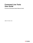
In the system synchronous SDR application example, shown in the following figure, the
data is transmitted from the source device on one rising clock edge and captured in the
FPGA device on the next rising clock edge.
TIming Constraints User Guide
UG612 (v 13.2) July 6, 2011
www.xilinx.com
9
Chapter 2: Timing Constraint Methodology
Figure X-Ref Target - Figure 2-1
Source Device
FPGA
Transmit
Edge
Data
Q
D
Q
D
REG
REG
CLK
CLK
Capture
Edge
System Clock
Data
Data
System Clock
X11047
Figure 2-1:
Simplified System Synchronous Interface with Associated SDR Timing
The global OFFSET IN constraint is the most efficient way to specify the input timing for a
system synchronous interface. In this method, one OFFSET IN constraint is defined for
each system synchronous input interface clock. This single constraint covers the paths of
all input data bits that are captured in synchronous elements triggered by the specified
input clock.
To specify the input timing:
•
Define the clock PERIOD constraint for the input clock associated with the interface
•
Define the global OFFSET IN constraint for the interface
Example
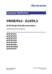
A timing diagram for an ideal System Synchronous SDR interface is shown in the
following figure. The interface has a clock period of 5 ns, The data for both bits of the bus
remains valid for the entire period.
Figure X-Ref Target - Figure 2-2
Transmit
Edge
Capture
Edge
PERIOD = 5 ns
SysClk
OFFSET IN BEFORE = 5ns
Data 1
Data
Data 2
Data
VALID = 5 ns
X11048
Figure 2-2:
Timing Diagram for an Ideal System Synchronous SDR Interface
The global OFFSET IN constraint is:
OFFSET = IN value VALID value BEFORE clock;
In the OFFSET IN constraint, the OFFSET=IN <value> determines the time from the
capturing clock edge to the time in which data first becomes valid. In this system
synchronous example, the data becomes valid 5 ns prior to the capturing clock edge. In the
OFFSET IN constraint, the VALID <value> determines the duration in which data
remains valid. In this example, the data remains valid for 5 ns.
10
www.xilinx.com
TIming Constraints User Guide
UG612 (v 13.2) July 6, 2011
Input Timing Constraints
For this example, the complete OFFSET IN specification with associated PERIOD
constraint is:
NET "SysCLk" TNM_NET = "SysClk";
TIMESPEC "TS_SysClk" = PERIOD "SysClk" 5 ns HIGH 50%;
OFFSET = IN 5 ns VALID 5 ns BEFORE "SysClk";
This global constraint covers both the data bits of the bus:
•
data1
•
data2
Source Synchronous Inputs
In a source synchronous input interface, a clock is regenerated and transmitted along with
the data from the source device along similar board traces. This clock is then used to
capture the data in the FPGA device. The board trace delays and board skew no longer
limit the operating frequency of the interface. The higher frequency also results in the
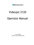
source synchronous input interface typically being a dual data rate (DDR) application. In
this source synchronous DDR application example, shown in the following figure, unique
data is transmitted from the source device on both the rising and falling clock edges and
captured in the FPGA device using the regenerated clock.
Figure X-Ref Target - Figure 2-3
Source Device
FPGA
Data
Q
D
Q
D
REG
REG
CLK
CLK
Clock
Clock
Data 1
Rising Data
Falling Data
Data 2
Rising Data
Falling Data
Q
D
REG
CLK
X11049
Figure 2-3:
Simplified Source Synchronous Input Interface with Associated DDR
Timing
The global OFFSET IN constraint is the most efficient way to specify the input timing for a
source synchronous interface. In the DDR interface, one OFFSET IN constraint is defined
for each edge of the input interface clock. These constraints cover the paths of all input data
bits that are captured in registers triggered by the specified input clock edge.
To specify the input timing:
•
Define the clock PERIOD constraint for the input clock associated with the interface
•
Define the global OFFSET IN constraint for the rising edge (RISING) of the interface
•
Define the global OFFSET IN constraint for the falling edge (FALLING) of the
interface
Example
A timing diagram for an ideal Source Synchronous DDR interface is shown in the
following figure. The interface has a clock period of 5 ns with a 50/50 duty cycle. The data
for both bits of the bus remains valid for the entire ½ period.
TIming Constraints User Guide
UG612 (v 13.2) July 6, 2011
www.xilinx.com
11
Chapter 2: Timing Constraint Methodology
Figure X-Ref Target - Figure 2-4
SysClk
OFFSET IN
=1.25 ns
Data 1
Data 2
OFFSET IN
=1.25 ns
Data
Data
Data
Data
VALID = 2.5 ns
Figure 2-4:
VALID = 2.5 ns
Timing Diagram for Ideal Source Synchronous DDR
The global OFFSET IN constraint for the DDR case is:
OFFSET = IN value VALID value BEFORE clock RISING;
OFFSET = IN value VALID value BEFORE clock FALLING;
In the OFFSET IN constraint, OFFSET=IN <value> determines the time from the
capturing clock edge in which data first becomes valid. In this source synchronous input
example, the rising data becomes valid 1.25 ns prior to the rising clock edge. The falling
data also becomes valid 1.25 ns prior to the falling clock edge. In the OFFSET IN constraint,
the VALID <value> determines the duration in which data remains valid. In this
example, both the rising and falling data remains valid for 2.5 ns.
For this example, the complete OFFSET IN specification with associated PERIOD
constraint is:
NET "SysCLk" TNM_NET = "SysClk";
TIMESPEC "TS_SysClk" = PERIOD "SysClk" 5 ns HIGH 50%;
OFFSET = IN 1.25 ns VALID 2.5 ns BEFORE "SysClk" RISING;
OFFSET = IN 1.25 ns VALID 2.5 ns BEFORE "SysClk" FALLING;
This global constraint covers both the data bits of the bus:
12
•
data1
•
data2
www.xilinx.com
TIming Constraints User Guide
UG612 (v 13.2) July 6, 2011
Register-To-Register Timing Constraints
Register-To-Register Timing Constraints
This section discusses Register-To-Register Timing Constraints and includes:
•
About Register-To-Register Timing Constraints
•
Automatically Related Synchronous DCM/PLL Clock Domains
•
Manually Related Synchronous Clock Domains
•
Asynchronous Clock Domains
About Register-To-Register Timing Constraints
Register-to-register or synchronous element to synchronous element path constraints cover the
synchronous data paths between internal registers. The PERIOD constraint:
•
Defines the timing requirements of the clock domains
•
Analyzes the paths within a single clock domain
•
Analyzes all paths between related clock domains
•
Takes into account all frequency, phase, and uncertainty differences between the clock
domains during analysis
For more information, see PERIOD Constraints in Chapter 3, Timing Constraint Principles.
The application and methodology for constraining synchronous clock domains falls under
several common cases. These categories include:
•
Automatically Related Synchronous DCM/PLL Clock Domains
•
Manually Related Synchronous Clock Domains
•
Asynchronous Clock Domains
By allowing the tools to automatically create clock relationships for DLL/DCM/PLL
output clocks, and manually defining relationships for externally related clocks, all
synchronous cross clock domain paths are covered by the appropriate constraints, and
properly analyzed. Using PERIOD constraints that follow this methodology eliminates the
need for additional cross-clock-domain constraints.
Automatically Related Synchronous DCM/PLL Clock Domains
The most common type of clock circuit is one in which:
•
The input clock is fed into a DLL/DCM/PLL
•
The outputs are used to clock the synchronous paths in the device
In this case, the recommended methodology is to define a PERIOD constraint on the input
clock to the DLL/DCM/PLL.
By placing the PERIOD constraint on the input clock, the Xilinx tools automatically:
•
Derive a new PERIOD constraint for each of the DLL/DCM/PLL output clocks
•
Determine the clock relationships between the output clock domains, and
automatically perform an analysis for any paths between these clock domains.
TIming Constraints User Guide
UG612 (v 13.2) July 6, 2011
www.xilinx.com
13
Chapter 2: Timing Constraint Methodology
Example
The circuit of an input clock driving a DCM is shown in the following figure.
Figure X-Ref Target - Figure 2-5
PERIOD = 5 ns
SysClk
OFFSET IN
=1.25 ns
Data 1
Data 2
OFFSET IN
=1.25 ns
Data
Data
Data
Data
VALID = 2.5 ns
VALID = 2.5 ns
X11050
Figure 2-5:
The Input Clock of the Design Goes to a DCM Example
The PERIOD constraint syntax for this example is:
NET "ClockName" TNM_NET = "TNM_NET_Name";
TIMESPEC "TS_name" = PERIOD "TNM_NET_Name" PeriodValue HIGH HighValue%;
In the PERIOD constraint, the PeriodValue defines the duration of the clock period. In
this case, the input clock to the DCM has a period of 5 ns. The HighValue of the PERIOD
constraint defines the percent of the clock waveform that is HIGH. In this example, the
waveform has a 50/50 duty cycle resulting in a HighValue of 50%.
The syntax for this example is:
NET "ClkIn" TNM_NET = "ClkIn";
TIMESPEC "TS_ClkIn" = PERIOD "ClkIn" 5 ns HIGH 50%;
Based on the input clock PERIOD constraint given above, the DCM automatically:
•
Creates two output clock constraints for the DCM outputs
•
Performs analysis between the two domains
Manually Related Synchronous Clock Domains
In some cases the relationship between synchronous clock domains can not be
automatically determined by the tools - for example, when related clocks enter the FPGA
device on separate pins. In this case, Xilinx recommends that you:
•
Define a separate PERIOD constraint for each input clock
•
Define a manual relationship between the clocks
Once you define the manual relationship, all paths between the two synchronous domains
are automatically analyzed. The analysis takes into account all frequency, phase, and
uncertainty information.
The Xilinx constraints system allows you to define complex manual relationships between
clock domains using the PERIOD constraint including clock frequency and phase
transformations.
14
www.xilinx.com
TIming Constraints User Guide
UG612 (v 13.2) July 6, 2011
Register-To-Register Timing Constraints
To define complex manual relationships between clock domains using the PERIOD
constraint:
•
Define the PERIOD constraint for the primary clock
•
Define the PERIOD constraint for the related clock using the first PERIOD constraint
as a reference
For more information on using the PERIOD constraint to define clock relationships, see
PERIOD Constraints in Chapter 3, Timing Constraint Principles.
Two related clocks enter the FPGA device through separate external pins, as shown in the
following figure.
•
The first clock (CLK1X) is the primary clock
•
The second clock (CLK2X180) is the related clock
Figure X-Ref Target - Figure 2-6
Q
D
Related Path
Transmit
Edge
Q
D
REG
REG
CLK
CLK
PERIOD = 5 ns
CLK1X
CLK1X
CLK2X180
CLK2X180
Capture
Edge
X11052
Figure 2-6:
Two Related Clocks Entering the FPGA Device Through Separate
External Pins
The PERIOD constraint syntax for this example is:
NET "PrimaryClock" TNM_NET = "TNM_Primary";
NET "RelatedClock" TNM_NET = "TNM_Related";
TIMESPEC "TS_primary" = PERIOD "TNM_Primary" PeriodValue HIGH HighValue%;
TIMESPEC "TS_related" = PERIOD "TNM_Related" TS_Primary_relation PHASE value;
In the related PERIOD definition, the PERIOD value is defined as a time unit (period)
relationship to the primary clock. The relationship is expressed in terms of the primary
clock TIMESPEC. In this example CLK2X180 operates at twice the frequency of CLK1X
which results in a PERIOD relationship of one-half.
In the related PERIOD definition, the PHASE value defines the difference in time between
the rising clock edge of the source clock and the related clock. In this example, since the
CLK2X180 clock is 180 degrees shifted, the rising edge begins 1.25 ns after the rising edge
of the primary clock.
The syntax for this example is:
NET "Clk1X" TNM_NET = "Clk1X";
NET "Clk2X180" TNM_NET = "Clk2X180";
TIMESPEC "TS_Clk1X" = PERIOD "Clk1X" 5 ns;
TIMESPEC "TS_Clk2X180" = PERIOD "Clk2X180" TS_Clk1X/2 PHASE + 1.25 ns ;
TIming Constraints User Guide
UG612 (v 13.2) July 6, 2011
www.xilinx.com
15
Chapter 2: Timing Constraint Methodology
Asynchronous Clock Domains
Asynchronous clock domains are those in which the source and destination clocks do not
have a frequency or phase relationship. Since the clocks are not related, it is not possible to
determine the final relationship for setup and hold time analysis. For this reason, Xilinx
recommends that you use proper asynchronous design techniques to ensure the successful
capture of data. One example of proper asynchronous design technique is to use a FIFO
design element to capture and transfer data between asynchronous clock domains. While
not required, in some cases you may wish to constrain the maximum data path delay in
isolation without regard to clock path frequency or phase relationship.
The Xilinx constraints system allows you to constrain the maximum data path delay
without regard to source and destination clock frequency and phase relationship. This
requirement is specified using the FROM-TO constraint with the DATAPATHONLY
keyword.
To constrain of the maximum data path delay without regard to source and destination
clock frequency and phase relationship:
•
Define a time group for the source synchronous elements
•
Define a time group for the destination synchronous elements
•
Define the maximum delay of the data paths using the FROM-TO constraint between
the two time groups with DATAPATHONLY keyword.
For more information on using the FROM-TO constraint with the DATAPATHONLY
keyword, see FROM:TO (Multi-Cycle) Constraints in Chapter 3, Timing Constraint
Principles.
Example
Two unrelated clocks enter the FPGA device through separate external pins as shown in
the following figure.
•
The first clock (CLKA) is the source clock
•
The second clock (CLKB) is the destination clock
Figure X-Ref Target - Figure 2-7
Q
D
Data_A_B
Q
D
REG
REG
CLK
CLK
CLKA
CLKB
X11053
Figure 2-7:
Two Unrelated Clocks Entering the FPGA Device Through Separate
External Pins
The syntax for this example is:
NET "CLKA" TNM_NET = FFS "GRP_A";
NET "CLKB" TNM_NET = FFS "GRP_B";
TIMESPEC TS_Example = FROM "GRP_A" TO "GRP_B" 5 ns DATAPATHONLY;
16
www.xilinx.com
TIming Constraints User Guide
UG612 (v 13.2) July 6, 2011
Output Timing Constraints
Output Timing Constraints
Output timing covers the data path from a register inside the FPGA device to the external
pin of the FPGA device. The OFFSET OUT constraint specifies the output timing. The best
way to specify the output timing requirements depends on the type (source/system
synchronous) and SDR/DDR of the interface.
The OFFSET OUT constraint defines the maximum time allowed for data to be transmitted
from the FPGA device. The output delay path begins at the input clock pin of the FPGA
device and continues through the output register to the data pins of the FPGA device, as
shown in the following figure.
Figure X-Ref Target - Figure 2-8
FPGA
Q
D
Data 1
REG
ClkIn
CLK
OFFSET OUT AFTER
Q
D
Data 2
REG
Data 1
Valid Data
Data 2
Valid Data
CLK
CLK_IN
X11054
Figure 2-8:
Output-Timing Constraints from Input Clock Pad to the Output Data Pad
When analyzing the OFFSET OUT constraint, the timing tools automatically take all
internal factors affecting the delay of the clock and data paths into account. These factors
include:
•
Frequency and phase transformations of the clock
•
Clock uncertainties
•
Data path delay adjustments
For more information, see OFFSET OUT Constraints in Chapter 3, Timing Constraint
Principles.
System Synchronous Output
The system synchronous output interface is an interface in which a common system clock
is used to both transfer and capture the data. Since this interface uses a common system
clock, only the data is transmitted from the FPGA device to the receiving device as shown
in the following figure.
TIming Constraints User Guide
UG612 (v 13.2) July 6, 2011
www.xilinx.com
17
Chapter 2: Timing Constraint Methodology
Figure X-Ref Target - Figure 2-9
FPGA
Receiving Device
Transmit
Edge
Data
Q
D
Capture
Edge
Q
D
REG
REG
CLK
CLK
System Clock
Data
Data
System Clock
X11055
Figure 2-9:
Simplified System Synchronous Output Interface with Associated SDR
Timing
If these paths must be constrained, the global OFFSET OUT constraint is the most efficient
way to specify the output timing for the system synchronous interface. In the global
method, one OFFSET OUT constraint is defined for each system synchronous output
interface clock. This single constraint covers the paths of all output data bits sent from
registers triggered by the specified input clock.
To specify the output timing:
•
Define a time name (TNM) for the output clock to create a time group, which contains
all output registers triggered, by the input clock
•
Define the global OFFSET OUT constraint for the interface
Example
A timing diagram for a System Synchronous SDR output interface is shown in the
following figure. The data in this example must become valid at the output pins a
maximum of 5 ns after the input clock edge at the pin of the FPGA device.
Figure X-Ref Target - Figure 2-10
FPGA
Q
D
Data 1
Input Clock Edge
REG
ClkIn
CLK
OFFSET OUT AFTER
5 ns
Q
D
Data 2
REG
Data 1
Valid Data
Data 2
Valid Data
CLK
ClkIn
X11056
Figure 2-10:
Timing Diagram for System Synchronous SDR Output Interface
The global OFFSET OUT constraint for the system synchronous interface is:
OFFSET = OUT value AFTER clock;
In the OFFSET OUT constraint, OFFSET=OUT <value> determines the maximum time
from the rising clock edge at the input clock port until the data first becomes valid at the
data output port of the FPGA device. In this system synchronous example, the output data
must become valid at least 5 ns after the input clock edge.
18
www.xilinx.com
TIming Constraints User Guide
UG612 (v 13.2) July 6, 2011
Output Timing Constraints
For this example, the complete OFFSET OUT specification is:
NET "ClkIn" TNM_NET = "ClkIn";
OFFSET = OUT 5 ns AFTER "ClkIn";
This global constraint covers both the data bits of the bus:
•
data1
•
data2
Source Synchronous Outputs
The source synchronous output interface is an interface in which a clock is regenerated and
transmitted along with the data from the FPGA device. The regenerated clock is
transmitted along with the data. The interface is primarily limited in performance by
system noise and the skew between the regenerated clock and the data bits, as shown in
the following figure. In this interface, the time from the input clock edge to the output data
becoming valid is not as important as the skew between the output data bits. In most cases,
it can be left unconstrained.
Figure X-Ref Target - Figure 2-11
FPGA
Q
D
Data 1
REG
ClkIn
CLK
VCC
Q
D
GND
ClkOut
CkOut
REG
Data 1
CLK
Rising Data
Falling Data
ClkIn
X11057
Figure 2-11:
Simplified Source Synchronous Output Interface with Associated DDR
Timing
The global OFFSET OUT constraint is the most efficient way to specify the output timing
for a source synchronous interface. In the DDR interface, one OFFSET OUT constraint is
defined for each edge of the output interface clock. These constraints cover the paths of all
output data bits that are transmitted by registers triggered with the specified output clock
edge.
To specify the input timing:
•
Define a time name (TNM) for the output clock to create a time group which contains
all output registers triggered by the output clock
•
Define the global OFFSET OUT constraint for the rising edge (RISING) of the interface
•
Define the global OFFSET OUT constraint for the falling edge (FALLING) of the
interface
TIming Constraints User Guide
UG612 (v 13.2) July 6, 2011
www.xilinx.com
19
Chapter 2: Timing Constraint Methodology
Example
A timing diagram for an ideal Source Synchronous DDR interface is shown in the
following figure. The interface has a clock period of 5 ns with a 50/50 duty cycle. The data
for both bits of the bus remains valid for the entire ½ period.
Figure X-Ref Target - Figure 2-12
PERIOD = 5 ns
SysClk
OFFSET IN
=1.25 ns
OFFSET IN
=1.25 ns
Data 1
Data
Data
Data 2
Data
Data
VALID = 2.5 ns
VALID = 2.5 ns
X11058
Figure 2-12:
Timing Diagram for an Ideal Source Synchronous DDR
In the OFFSET OUT constraint, OFFSET=OUT <value> determines the maximum time
from the rising clock edge at the input clock port until the data first becomes valid at the
data output port of the FPGA device. When <value> is omitted from the OFFSET OUT
constraint, the constraint becomes a report-only specification which reports the skew of the
output bus. The REFERENCE_PIN keyword defines the regenerated output clock as the
reference point against which the skew of the output data pins is reported.
For this example, the complete OFFSET OUT specification for both the rising and falling
clock edges is :
NET “CLkIn” TNM_NET = “ClkIn”;
OFFSET = OUT AFTER “ClkIn” REFERENCE_PIN “ClkOut” RISING;
OFFSET = OUT AFTER “ClkIn” REFERENCE_PIN “ClkOut” FALLING;
20
www.xilinx.com
TIming Constraints User Guide
UG612 (v 13.2) July 6, 2011
Timing Exceptions
Timing Exceptions
Using the global definitions of the input, register-to-register, and output timing
constraints, properly constrains the majority of the paths. In certain cases a small number
of paths contain exceptions to the global constraint rules. The most common types of
exceptions are:
•
False Paths
•
Multi-Cycle Paths
False Paths
In some cases, you may want to remove a set of paths from timing analysis if you are sure
that these paths do not affect timing performance.
One common way to specify the set of paths to be removed from timing analysis is to use
the FROM-TO constraint with the timing ignore (TIG) keyword. This allows you to:
•
Specify a set of registers in a source time group
•
Specify a set of registers in a destination time group
•
Automatically remove all paths between those time groups from analysis.
To specify the timing ignore (TIG) constraint for this method, define:
•
A set of registers for the source time group
•
A set of registers for the destination time group
•
A FROM-TO constraint with a TIG keyword to remove the paths between the groups
Example
A hypothetical case in which a path between two registers does not affect the timing of the
design, and is desired to be removed from analysis, is shown in the following figure
Figure X-Ref Target - Figure 2-13
Q
D
Ignored Path
Q
D
REG
REG
CLK
CLK
CLK1
CLK2
X11059
Figure 2-13:
Path Between Two Registers That Does Not Affect the Timing of the
Design
The generic syntax for defining a timing ignore (TIG) between time groups is:
TIMESPEC "TSid" = FROM "SRC_GRP" TO "DST_GRP" TIG;
In the FROM-TO TIG example, the SRC_GRP defines the set of source registers at which
path tracing begins. The DST_GRP defines the set of destination registers at which the path
tracing ends. All paths that begin in the SRC_GRP and end in the DST_GRP are ignored.
TIming Constraints User Guide
UG612 (v 13.2) July 6, 2011
www.xilinx.com
21
Chapter 2: Timing Constraint Methodology
The specific syntax for this example is:
NET "CLK1" TNM_NET = FFS "GRP_1";
NET "CLK2" TNM_NET = FFS "GRP_2";
TIMESPEC TS_Example = FROM "GRP_1" TO "GRP_2" TIG;
Multi-Cycle Paths
In a multi-cycle path, data is transferred from source to destination synchronous elements
at a rate less than the clock frequency defined in the PERIOD specification.
This occurs most often when the synchronous elements are gated with a common clock
enable signal. By defining a multi-cycle path, the timing constraints for these synchronous
elements are relaxed over the default PERIOD constraint. The multi-cycle path constraint
can be defined with respect to the PERIOD constraint identifier (TS_clk125) and state the
multiplication or the number of period cycles (TS_clk125 * 3). The implementation
tools are then able to appropriately prioritize the implementation of these paths.
One common way to specify the set of multi-cycle paths is to define a time group using the
clock enable signal. This allows you to:
•
Define one time group containing both the source and destination synchronous
elements using a common clock enable signal
•
Automatically apply the multi-cycle constraint to all paths between these
synchronous elements
To specify the FROM:TO (multi-cycle) constraint for this method, define:
•
A PERIOD constraint for the common clock domain
•
A set of registers based on a common clock enable signal
•
A FROM:TO (multi-cycle) constraint describing the new timing requirement
Example
The following figure shows a hypothetical case in which a path between two registers is
clocked by a common clock enable signal. In this example, the clock enable is toggled at a
rate that is one-half of the reference clock.
Figure X-Ref Target - Figure 2-14
Q
D
REG
CLK
EN
Q
D
REG
CLK
EN
Mutiple-Cycle Path
Q
D
Q
D
REG
CLK
EN
REG
CLK
EN
CLK1
Enable
Figure 2-14:
X11060
Path Between Two Registers Clocked by a Common Clock Enable
Signal
The generic syntax for defining a multi-cycle path between time groups is:
TIMESPEC "TSid" = FROM "MC_GRP" TO "MC_GRP" <value>;
In the FROM:TO (multi-cycle) example, the MC_GRP defines the set of registers which are
driven by a common clock enable signal. All paths that begin in the MC_GRP and end in
the MC_GRP have the multi-cycle timing requirement applied to them. Paths into and out
of the MC_GRP are analyzed with the appropriate PERIOD specification.
22
www.xilinx.com
TIming Constraints User Guide
UG612 (v 13.2) July 6, 2011
Timing Exceptions
The specific syntax for this example is:
NET "CLK1" TNM_NET = "CLK1";
TIMESPEC "TS_CLK1" = PERIOD "CLK1" 5 ns HIGH 50%;
NET "Enable" TNM_NET = FFS "MC_GRP";
TIMESPEC TS_Example = FROM "MC_GRP" TO "MC_GRP" TS_CLK1*2;
TIming Constraints User Guide
UG612 (v 13.2) July 6, 2011
www.xilinx.com
23
Chapter 2: Timing Constraint Methodology
24
www.xilinx.com
TIming Constraints User Guide
UG612 (v 13.2) July 6, 2011
Chapter 3
Timing Constraint Principles
This chapter:
•
•
Discusses the fundamentals of timing constraints, including:
•
PERIOD Constraints
•
OFFSET Constraints
•
FROM:TO (Multi-Cycle) Constraints
Discusses the ability to group elements in order to provide a better understanding of
the constraint system subsystem
Constraint System
This section discusses the Constraint System and includes:
•
About the Constraint System
•
DLL/DCM/PLL/BUFR/PMCD Components
•
Timing Group Creation with TNM/TNM_NET Attributes
•
Grouping Constraints
About the Constraint System
The constraint system is that portion of the implementation tools (NGDBUILD) that parses
and understands the physical and timing constraints for the design.
The constraint system:
•
Parses the constraints from the following files and delivers this information to the
other implementation tools:
•
NCF
•
XCF
•
EDN/EDF/EDIF
•
NGC
•
NGO
•
Confirms that the constraints are correctly specified for the design
•
Applies the necessary attributes to the corresponding elements
•
Issues error and warning messages for constraints that do not correlate correctly with
the design
TIming Constraints User Guide
UG612 (v 13.2) July 6, 2011
www.xilinx.com
25
Chapter 3: Timing Constraint Principles
DLL/DCM/PLL/BUFR/PMCD Components
This section discusses DLL/DCM/PLL/BUFR/PMCD Components and includes:
•
About DLL/DCM/PLL/BUFR/PMCD Components
•
Transformation Conditions
•
New PERIOD Constraints on DCM Outputs
•
Synchronous Elements
•
Analysis with NET PERIOD
•
PHASE Keyword
•
DLL/DCM/PLL Manipulation with PHASE
About DLL/DCM/PLL/BUFR/PMCD Components
When a TIMESPEC PERIOD specification on the input pad clock net is traced or translated
through the DCM/DLL/PLL/BUFR/PMCD component (also known as a clockmodifying block), the derived or output clocks are constrained with new PERIOD
constraints.
In order to generate the destination-element-timing group, during transformation each
clock output pin of the clock-modifying block is given:
•
A new TIMESPEC PERIOD constraint
•
A corresponding TNM_NET constraint
The new TIMESPEC PERIOD constraint is based upon the manipulation of the clock
modifying block component. The transformation:
•
Takes into account the phase relationship factor of the clock outputs
•
Performs the appropriate multiplication or division of the PERIOD requirement value
Transformation Conditions
The transformation occurs when:
•
The TIMESPEC PERIOD constraint is traced into the CLKIN pin of the clock
modifying block component, and
•
The following conditions are met:
•
The group associated with the PERIOD constraint is used in exactly one PERIOD
constraint
•
The group associated with the PERIOD constraint is not used in any other timing
constraints, including FROM:TO (multicycle) or OFFSET constraints
•
The group associated with the PERIOD constraint is not referenced or related to
any other user group definition
New PERIOD Constraints on DCM Outputs
If the Transformation Conditions are met, the TIMESPEC "TS_clk20" = PERIOD
"clk20_grp" 20 ns HIGH 50 %; constraint is translated into the following constraints
based upon the clock structure shown in the following figure.
CLK0:
TS_clk20_0=PERIOD clk20_0 TS_clk20*1.000000 HIGH 50.000000%
CLK90: TS_clk20_90=PERIOD clk20_90 TS_clk20*1.000000 PHASE + 5.000000
nS HIGH 50.000000%
26
www.xilinx.com
TIming Constraints User Guide
UG612 (v 13.2) July 6, 2011
Constraint System
Figure X-Ref Target - Figure 3-1
DCM
clk20
CLKIN
CLK0
clk20_0
CLK90
clk20_90
X11061
Figure 3-1: New PERIOD Constraints on DCM Outputs
The following message appears in the NGDBuild (design.bld) or MAP (design.mrp)
report:
INFO:XdmHelpers:851 - TNM " clk20_grp ", used in period specification
"TS_clk20", was traced into DCM instance "my_dcm". The following new TNM
groups and period specifications were generated at the DCM output(s):
clk0: TS_clk20_0=PERIOD clk20_0 TS_clk20*1.000000 HIGH 50.000000%
clk90: TS_clk20_90=PERIOD clk20_90 TS_clk20*1.000000 PHASE + 5.000000
nS HIGH 50.000000%
If the CLKIN_DIVIDE_BY_2 attribute is set to TRUE for the DCM in the figure above, the
translated PERIOD constraints are adjusted accordingly. The following constraints are the
result of this attribute:
CLK0:
TS_clk20_0=PERIOD clk20_0 TS_clk20*2.000000 HIGH 50.000000%
CLK90: TS_clk20_90=PERIOD clk20_90 TS_clk20*2.000000 PHASE + 5.000000
nS HIGH 50.000000%
If the Transformation Conditions are not met:
•
The PERIOD constraint is not placed on the output or derived clocks of the clock
modifying block component, and
•
An error or warning message is reported in the NGDBuild report
Error Message Example
Following is an example of an error message:
"ERROR:NgdHelpers:702 - The TNM "PAD_CLK" drives the CLKIN pin of CLKDLL
"$I1". This TNM cannot be traced through the CLKDLL because it is not
used in exactly one PERIOD specification. This TNM is used in the
following user groups and/or specifications:
TS_PAD_CLK=PERIOD PAD_CLK 20000.000000 pS HIGH 50.000000%
TS_01=FROM PAD_CLK TO PADS 20000.000000 pS"
Note: The original TIMESPEC PERIOD constraint is reported in the timing report and shows "0
items analyzed."
The newly created TIMESPEC PERIOD constraints contain all the paths associated with
the clock modifying block component. If the PERIOD constraint is not translated and then
traces only to the clock modifying block component, the timing report show 0 items
analyzed. No other PERIOD constraints are reported.
If the PERIOD constraint traces to other synchronous elements, the analysis includes only
those synchronous elements.
TIming Constraints User Guide
UG612 (v 13.2) July 6, 2011
www.xilinx.com
27
Chapter 3: Timing Constraint Principles
Synchronous Elements
Synchronous elements include:
•
Flip Flops
•
Latches
•
Distributed RAM
•
Block RAM
•
Distributed ROM
•
ISERDES
•
OSERDES
•
PPC405
•
PPC440
•
MULT18X18
•
DSP48
•
MGTs (GT, GT10, GT11, GTP)
•
SRL16
•
EMAC
•
FIFO (16, 18, & 36)
•
PCIE
•
TEMAC
Analysis with NET PERIOD
When a NET PERIOD constraint is applied to the input clock pad or net, this constraint is
not translated through the clock modifying block component. This can result in zero items
or paths analyzed for these constraints.
The NET PERIOD is analyzed only during MAP, PAR, and Timing analysis. When "MAP timing" and PAR call the timing tools, the timing tools do the clock modifying block
manipulation for placement and routing, but not for the timing analysis timing reports.
When a TIMESPEC PERIOD constraint is traced into an input pin on a clock modifying
block, NGDBuild or the translate process transforms the original TIMESPEC PERIOD
constraint into new TIMESPEC PERIOD constraints based upon the derived output clocks.
The NGDBuild report (design.bld) indicates this transformation.
MAP, PAR, and Timing Analyzer use the new derived clock TIMESPEC PERIOD
constraints that are propagated to the Physical Constraints File (PCF). The original
TIMESPEC PERIOD is unchanged during this transformation. It is used as a reference for
the new TIMESPEC PERIOD constraints.
Note: Constraints Editor sees only the original PERIOD constraint and not the newly transformed
PERIOD constraints.
PHASE Keyword
The PHASE keyword is used in the relationship between related clocks. The timing
analysis tools use this relationship for the OFFSET constraints and cross-clock domain path
analysis. The PHASE keyword can be entered in the UCF/NCF or through the translation
of the DCM/DLL/PLL components during NGDBuild.
28
www.xilinx.com
TIming Constraints User Guide
UG612 (v 13.2) July 6, 2011
Constraint System
Note: If the phase shifted value of DCM/PLL/DLL component is changed in FPGA Editor, the
change is not reflected in the PCF file.
The timing analysis tools use the PHASE keyword value in the PCF to emulate the
DLL/DCM/PLL phase shift value. In order to see the change that was made in FPGA
Editor, the PCF must also be modified manually with the corresponding change.
DLL/DCM/PLL Manipulation with PHASE
The following table displays the new DCM/DLL/PLL component output clock net
derived TIMESPEC PERIOD constraints, based upon the original PERIOD (TS_CLKIN)
constraints. TS_CLKIN is expressed as a time value.
If TS_CLKIN is expressed as a frequency value, the multiply and divide operations are
reversed. If the DCM attributes FIXED_PHASE_SHIFT or VARIABLE_PHASE_SHIFT are
used, the amount of the phase-shifted value is included in the PHASE keyword value.
The DCM attributes FIXED_PHASE_SHIFT or VARIABLE_PHASE_SHIFT phase shifting
amount on the DCM is not reflected in the following table.
Table 3-1:
Transformation of PERIOD Constraint Through DCM
Output Pin
PERIOD Value
PHASE Shift value
CLK0
TS_CLKIN * 1
None
CLK90
TS_CLKIN * 1
PHASE + (clk0_period * ¼)
CLK180
TS_CLKIN * 1
PHASE + (clk0_period * ½)
CLK270
TS_CLKIN * 1
PHASE + (clk0_period * ¾)
CLK2x
TS_CLKIN / 2
None
CLK2x180
TS_CLKIN / 2
PHASE + (clk2x_period * ½)
CLKDV
TS_CLKIN * clkdv_divide
None
(clkdv_divide = value of
CLKDV_DIVIDE property
(default = 2.0))
CLKFX
TS_CLKIN / clkfx_factor
None
(clkfx_factor = value of
CLKFX_MULTIPLY property (default
= 4.0) divided by value of
CLKFX_DIVIDE property
(default = 1.0))
CLKFX180
TS_CLKIN / clkfx_factor
PHASE + (clkfx_period * ½)
(clkfx_factor = value of
CLKFX_MULTIPLY property (default
= 4.0) divided by value of
CLKFX_DIVIDE property
(default = 1.0))
TIming Constraints User Guide
UG612 (v 13.2) July 6, 2011
www.xilinx.com
29
Chapter 3: Timing Constraint Principles
Timing Group Creation with TNM/TNM_NET Attributes
This section discusses Timing Group Creation with TNM/TNM_NET Attributes and
includes:
•
About Timing Group Creation with TNM/TNM_NET Attributes
•
Net Connectivity (NET)
•
Predefined Time Groups
•
Propagation Rules for TNM_NET
•
Instance or Hierarchy
•
Instance Pin
About Timing Group Creation with TNM/TNM_NET Attributes
All design elements with same TNM/TNM_NET attribute are considered a timing group.
A design element may be in multiple timing groups (TNM/TNM_NET).
The TNM/TNM_NET attributes can be applied to:
•
Net Connectivity (NET)
•
Instance/Module - INST
•
Instance Pin - PIN
Note: To ensure correct timing analysis, Xilinx® recommends that you place only one
TNM/TNM_NET on each element, driver pin, or macro driver pin.
Net Connectivity (NET)
Identifying groups by net connectivity allows the grouping of elements by specifying a net
or signal that eventually drives synchronous elements and pads. This method is a good
way to identify multi-cycle path elements that are controlled by a clock enable and can be
constrained as a FROM:TO (multi-cycle) constraint. This method uses TNM_NET (timing
net) or TNM (timing name) on a net of the design. The timing name attribute is commonly
used on HDL port declarations, which are directly connected to pads.
If a timing name attribute is placed on a net or signal, the constraints parser traces the
signal or net downstream to the synchronous elements. A timing name is an attribute that
can be used to identify the elements that make up a time group that can be then used in a
timing constraint. Those synchronous elements are then tagged with the same timing
name attribute. The timing name attribute name is then used in a TIMESPEC or Timing
Constraint.
An example is the clock net in following schematic is traced forward to the two flip-flops in
the following figure.
30
www.xilinx.com
TIming Constraints User Guide
UG612 (v 13.2) July 6, 2011
Constraint System
Figure X-Ref Target - Figure 3-2
Q
D
Q
D
OUT1
CLOCK
OUT2
X11062
Figure 3-2:
TNM on the CLOCK Pad or Net Traces Downstream to the Flip-Flops
Flagging a common input (typically a clock signal or clock enable signal) can be used to
group flip-flops, latches, or other synchronous elements. The TNM is traced forward along
the path (through any number of gates, buffers, or combinatorial logic) until it reaches a
flip-flop, input latch, or synchronous element. Those elements are added to the specified
TNM or time group. Using TNM on a net that traces forward to create a group of flip-flops
is shown in the following figure.
Figure X-Ref Target - Figure 3-3
IPAD
I
Pxx
AIN0
I
IBUF
O
A0
TNM=FLOPS 1
O D1
2
XNOR
IPAD
I
Pxx
BIN0
IBUF
O B0
1
I
FD
OBUF
OPAD
Q BIT0 I
O BIT00 O Pxx
FD
Q BIT1 I
FD
Q BIT2 I
C
O D2
2
D
AND
OBUF
D
O BIT01 O
OPAD
Pxx
C
O
D3
INV
OBUF
D
C
O BIT02 O
OPAD
Pxx
GCLK
IPAD
I CLKIN
Pxx
I
O
CLK
O CLKN
I
INV
Figure 3-3:
X11063
TNM on the CLK Net Traced Through Combinatorial Logic to
Synchronous Elements (Flip-Flops)
When you place a TNM constraint on a net, use a qualifier to narrow the list of elements in
the time group. A qualified TNM is traced forward until it reaches the first synchronous
element that matches the qualifier type. The qualifier types are the predefined time groups.
If that type of synchronous element matches the qualifier, the synchronous element is
given that TNM attribute. Whether or not there is a match, the TNM is not traced through
the synchronous element.
TIming Constraints User Guide
UG612 (v 13.2) July 6, 2011
www.xilinx.com
31
Chapter 3: Timing Constraint Principles
Predefined Time Groups
The following keywords are predefined time groups:
•
FFS
All SLICE and IOB edge-triggered flip-flops and shift registers
•
PADS
All I/O pads
•
•
DSPS
•
All DSP48 in Virtex™-4 devices
•
All DSP48E in Virtex-5 devices
RAMS
All single-port and dual-port SLICE LUT RAMs and block Rams
•
MULTS
All synchronous and asynchronous multipliers in the following devices:
•
•
VirtexII-Pro
•
VirtexII-ProX
•
Virtex-4
•
Virtex-5
HSIOS
•
•
•
-
VirtexII-Pro
-
VirtexII-ProX
-
Virtex-4
All GTP in Virtex-5 devices
CPUS
•
•
•
All GT and GT10 in the following devices:
All PPC405 in the following devices:
-
VirtexII-Pro
-
VirtexII-ProX
-
Virtex-4
All PPC450 in Virtex-5 devices
LATCHES
All SLICE level-sensitive latches
•
BRAMS_PORTA
Port A of all dual-port block RAMs
•
BRAMS_PORTB
Port B of all dual-port block RAMs
The TNM_NET is equivalent to TNM on a net, but produces different results on pad nets.
The Translate Process or NGDBuild command never transfers a TNM_NET constraint
from the attached net to an input pad, as it does with the TNM constraint. You can use
TNM_NET only with nets. If TNM_NET is used with any other objects (such as a pin or
instance), a warning is generated and TNM_NET definition is ignored.
32
www.xilinx.com
TIming Constraints User Guide
UG612 (v 13.2) July 6, 2011
Constraint System
A TNM attribute on a pad net or the net between the IPAD and the IBUF, the constraints
parser traces the signal or net upstream to the pad element, as shown in the following
figure. The TNM_NET attribute is traced through the buffer to the synchronous elements.
In HDL designs, the IBUF output signal is the same as the IPAD or port name, so there are
not differences between the TNM_NET and TNM attributes. In this case, both timing name
attributes trace downstream to the synchronous elements.
Propagation Rules for TNM_NET
The propagation rules for TNM_NET are:
•
If applied to a pad net, TNM_NET propagates forward through the IBUF elements
and any other combinatorial logic to synchronous elements or pads.
•
If applied to a clock-pad net, TNM_NET propagates forward through the clock buffer
to synchronous elements or pads.
•
If applied to an input clock net of a DCM/DLL/PLL/PMCD/BUFR and associated
with a PERIOD constraint, TNM_NET propagates forward through the clockmodifying block to synchronous elements or pads.
Figure X-Ref Target - Figure 3-4
FF1
PADCLK
INTCLK
C
IBUF
IPAD
FF2
C
X11064
Figure 3-4:
Differences between TNM and TNM_NET
In the design shown in the figure above, a TNM associated with the IPAD signal includes
only the PAD symbol as the member of a time group. A TNM_NET associated with the
IPAD signal includes all the synchronous elements after the IBUF as members of a time
group.
Following are examples of different ways to create time groups using the IPAD signal:
•
NET PADCLK TNM = PAD_grp;
Use the padclk net to define the time group PAD_grp. Contains the IPAD element.
•
NET PADCLK TNM = FFS "FF_grp";
Use the padclk net to define the time group FF_grp. Contains no flip-flop elements.
•
NET PADCLK TNM_NET = FFS FF2_grp;
Use the padclk net to define the time group FF2_grp. Contains all flip-flop elements
associated with this net.
In the design shown in the figure above, a TNM associated with the IBUF output signal can
only include the synchronous elements after the IBUF as members of a time group.
Following are examples of time groups that use only the IBUF output signal:
•
NET INTCLK TNM = FFS FF1_grp;
Use the intclk net to define the time group FF1_grp. Contains all flip-flop elements
associated with this net.
TIming Constraints User Guide
UG612 (v 13.2) July 6, 2011
www.xilinx.com
33
Chapter 3: Timing Constraint Principles
•
NET INTCLK TNM_NET = RAMS Ram1_grp;
Use the intclk net to define the time group Ram1_grp. Contains all distributed and
block RAM elements associated with this net.
Instance or Hierarchy
When a TNM attribute is placed on a module or macro, the constraints parser traces the
macro or module down the hierarchy to the synchronous elements and pads. The attribute
transverses through all levels of the hierarchy rather than forward along a net or signal.
This feature is illustrated in:
•
Figure 3-2, TNM on the CLOCK Pad or Net Traces Downstream to the Flip-Flops
•
Figure 3-3, TNM on the CLK Net Traced Through Combinatorial Logic to
Synchronous Elements (Flip-Flops)
Those synchronous elements are then tagged with the same TNM attribute. The TNM
attribute name is then used in a TIMESPEC or timing constraint. This method uses a TNM
on a block of the design. Multiple instances of the same TNM attribute are used to identify
the time group.
A macro or module is an element that performs some general purpose higher level
function. It typically has a lower level design that consists of primitives or elements, other
macros or modules, or both, connected together to implement the higher level function.
A TNM constraint attached to a module or macro indicates that all elements inside the
macro or module (at all levels of hierarchy below the tagged module or macro) are part of
the named time group. Use the keep_hierarchy attribute to ensure that the design
hierarchy is maintained. This feature is illustrated in the following figures.
Figure X-Ref Target - Figure 3-5
34
www.xilinx.com
TIming Constraints User Guide
UG612 (v 13.2) July 6, 2011
Constraint System
TNM=FFS:FLOPS;RAMS:MEM
Q5
Q4
Q3
Q2
Q1
Q0
EN
DI
DO
ADDRS
WE
I
O
POS
PH0
PH1
PH2
PH3
NEG
D Q
EN
DI
DO
ADDRS
WE
EN
D Q
X11065
Figure 3-5:
The TNM on the Upper Left Hierarchy is Traced Down to the Lower
Level Element
Figure X-Ref Target - Figure 3-6
LOGIC
Q
D
LOGIC
D
Q
CLK
TNM=FLOPS
D
Q
TNM=FLOPS
Figure 3-6:
X11066
Grouping via Instances
You can use wildcard characters to transverse the hierarchy of a design.
•
A question mark (?) represents one character.
•
An asterisk (*) represents multiple characters.
The following example uses a wildcard character to transverse the hierarchy where
Level1 is a top level module:
•
Level1/*
Transverses all blocks in Level1 and below
TIming Constraints User Guide
UG612 (v 13.2) July 6, 2011
www.xilinx.com
35
Chapter 3: Timing Constraint Principles
•
Level1/*/
Transverses all blocks in Level1 but no further
The instances described below are either:
•
Symbols on a schematics, or
•
A symbol name as it appears in the EDIF netlist
An example of the wildcard transversing the design hierarchy is shown in the figure
above, for the following instances:
•
INST *
All synchronous elements are in this time group
•
INST /*
All synchronous elements are in this time group
•
INST /*/
Top level elements or modules are in this time group:
•
•
A1
•
B1
•
C1
INST A1/*
All elements one or more levels of hierarchy below the A1 hierarchy are in this time
group:
•
•
A21
•
A22
•
A3
•
A4
INST A1/*/
All elements one level of hierarchy below the A1 hierarchy are in this time group:
•
•
A21
•
A22
INST A1/*/*
All elements two or more levels of hierarchy below the A1 hierarchy are in this time
group:
•
•
A3
•
A4
INST A1/*/*/
All elements two levels of hierarchy below the A1 hierarchy are in this time group:
•
•
A3
INST A1/*/*/*
All elements three or more levels of hierarchy below the A1 hierarchy are in this time
group:
•
36
A4
www.xilinx.com
TIming Constraints User Guide
UG612 (v 13.2) July 6, 2011
Constraint System
•
INST A1/*/*/*/
All elements three levels of hierarchy below the A1 hierarchy are in this time group:
•
•
A4
INST /*/*22/
All elements with instance name of 22 are in this time group:
•
•
A22
•
B22
•
C22
INST /*/*22
All elements with instance name of 22 and elements one level of hierarchy below are in
this time group:
•
A22
•
A3
•
A4
•
B22
•
B3
•
C22
•
C3
Figure X-Ref Target - Figure 3-7
$A1
$A21
$B1
$A22
$B21
$A3
$C1
$B22
$B3
$C21
$C22
$C3
$A4
X11067
Figure 3-7:
Transversing Hierarchy with Wildcards
Instance Pin
Identifying groups by pin connectivity allows you to group elements by specifying a pin
that eventually drives synchronous elements and pads. This method uses TNM (timing
name) on a pin of the design. If a TNM attribute is placed on a pin, the constraints parser
traces the pin downstream to the synchronous elements. A TNM is an attribute that can be
used to identify the elements that make up a time group that can be then used in a timing
constraint.
TIming Constraints User Guide
UG612 (v 13.2) July 6, 2011
www.xilinx.com
37
Chapter 3: Timing Constraint Principles
An example of this method is shown in the following figure.
Figure X-Ref Target - Figure 3-8.
TNM=FFS:FLOPS
FLOPS
DI DO
DI DO
ADDRS
WE
MEM
I
0
D
O
WE
A0
A1
A2
A3
D Q
EN
DI DO
ADDRS
WE
EN
D Q
FLOPS
X11068
Figure 3-8:
TNM Placed on Macro Pin Traces Downstream to Synchronous
Elements
When placing a TNM constraint on a pin, a qualifier can be used to narrow the list of
elements in the time group. A qualified TNM is traced forward until it reaches the first
synchronous element hat matches the qualifier type. The qualifier types are the predefined
time groups. If that type of synchronous element matches the qualifier, the synchronous
element is given that TNM attribute. Whether or not there is a match, the TNM is not
traced through the synchronous element. For more information, see Predefined Time
Groups.
38
www.xilinx.com
TIming Constraints User Guide
UG612 (v 13.2) July 6, 2011
Constraint System
Grouping Constraints
Grouping constraints allow you to group similar elements together for timing analysis.
They can be defined in the following files:
•
UCF
•
NGC
•
EDN
•
EDIF/EDF
The timing analysis is on timing constraints, which are applied to logical paths. The logic
paths typically start and stop at pads and synchronous elements. The grouped elements
signify the starting and ending points for timing analysis. These starting and ending points
can be based upon predefined groups, user-defined groups, or both. The timing groups are
ideal for identifying groups of logic that operate at different speeds, or have different
timing requirements.
The time groups are used in the timing analysis of the design. The user-defined and
predefined time group informs the timing analysis tools the start and end points for each
path being analyzed. The time groups are used in the following constraints:
•
PERIOD
•
OFFSET IN
•
OFFSET OUT
•
FROM:TO (Multi-cycle)
•
TIG (Timing Ignore)
When using a specific net or instance name, you must use its full hierarchical path name.
This allows the implementation tools to find the net or instance. The pattern matching
wildcards can be used to specify when creating time groups with predefined time group
qualifiers. This is done by using placing a pattern in parenthesis after the time group
qualifier.
The predefined groups can reference all the following (among others):
•
Flip-flops
•
Latches
•
Pads
•
RAMs
•
CPUs
•
Multipliers
•
High-speed-input/outputs
The predefined group keywords can be used globally, and to create user-defined subgroups. The predefined time groups are considered reserved keywords that define the
types of synchronous elements and pads in the FPGA device.
For more information, see Predefined Time Groups.
The user-defined time group name is case sensitive and can overlap with other userdefined time group and with predefined time groups. An example of design elements
being is multiple time groups. In those cases, a register is in the FFS predefined time group,
but is also in the clk time group, which is associated with the PERIOD constraint.
TIming Constraints User Guide
UG612 (v 13.2) July 6, 2011
www.xilinx.com
39
Chapter 3: Timing Constraint Principles
Use the following keywords to define user-defined time groups:
•
TNM
•
TNM_NET
•
TIMEGRP
If the instance or net associated with the user-defined time group matches internal
reserved words, the time group or constraint is rejected. The same is true for the userdefined time group name. In all the constraints files (NCF, UCF, and PCF), instances, or
variable names that match internal reserved words, may be rejected unless the names are
enclosed in double quotes. If the instance or net name does match an internal reserved
word, enclose the name in double quotes. Double quotes are mandatory if the instance or
net name contains special characters such as the tilde (~) or dollar sign ($). Xilinx
recommends using double quotes on all net and instances.
All elements with the same TNM or TNM_NET attributes are considered a timing group.
For more information about TNM and TNM_NET attributes, see Constraint System.
The TIMEGRP attribute is to combine existing time groups (pre-defined or user-defined)
together or remove common elements from existing time groups, and create a new userdefined time group. The TIMEGRP attribute is also a method for creating a new time group
by pattern matching (grouping a set of objects that all have output nets that begin with a
given string).
Use the following keywords to create subsets of an existing time group:
•
Rising edge synchronous elements (RISING)
•
Falling edge synchronous elements (FALLING)
•
Remove common elements (EXCEPT)
Use the EXCEPT keyword with a TIMEGRP attribute to remove elements from an alreadycreated time group. The overlapping items to be removed from the original time group
must be in the excluded or EXCEPT time group. If the excluded time group does not
overlap with the original time group, none of the design elements are removed. In that
case, the new time group contains the same elements as the original time group.
In addition to using TIMEGRP to include multiple time groups or exclude multiple time
groups, it also can be used to create sub-groups using the RISING and FALLING
keywords. Use RISING and FALLING to create groups based upon the synchronous
element triggered clocking edge (rising or falling edges).
Pattern Matching
Pattern matching on either net or instance names can define the user-defined time group.
Use wildcard characters to define a user-defined time group of symbols whose associated
net name or instance name matches a specific pattern. Wildcards are used to generalize the
group selection of synchronous elements. Wildcards can also be used to shorten and
simplify the full hierarchical path to the synchronous elements.
Pattern matching is as follows:
•
Asterisk (*)
Matches any string of zero or more characters
•
Question Mark (?)
Matches a single character
40
www.xilinx.com
TIming Constraints User Guide
UG612 (v 13.2) July 6, 2011
Constraint System
Table 3-2:
Pattern Matching Examples
String
Indicates
Examples
DATA*
any net or instance name that
begins with DATA
DATA1, DATA22, and
DATABASE
NUMBER?
any net names that begin
with NUMBER and ends with
one single character
NUMBER1 or NUMBERS, but
not NUNMBER or NUMBER12
A pattern may contain more than one wildcard character. For example, *AT? specifies any
net name that:
•
Begins with one or more characters followed by AT, and
•
Ends with any one character
Following are examples of net names included in *AT?:
•
BAT2
•
CAT4
•
THAT9
Time Group Examples
Following are six time group examples.
Time Group Example One (Predefined Group of RAMs)
Following is an example of a time group created with a search string and a predefined
group of RAMs in a multicycle constraint:
•
INST my_core TNM = RAMS my_rams;
This time group (my_rams) is the RAM components of the hierarchical block my_core
•
TIMSPEC TS01 = FROM FFS TO my_rams 14.24ns;
•
NET clock_enable TNM_NET = RAMS(address*) fast_rams;
This time group (fast_rams) is the RAM components driven by net name of
clock_enable with an output net name of address*
•
TIMSPEC TS01 = FROM FFS TO fast_rams 12.48ns; OR
•
TIMESPEC TS01 = FROM FFS TO RAMS(address*) 12.48ns;
The Destination time group is based upon RAM components with an output net name
of address*,
Time Group Example Two (Predefined Group of FFS)
Following is an example of a time group created with a search string and a predefined
group of FFS in a multi-cycle constraint:
TIMESPEC TS01 = FROM RAMS TO FFS(macro_A/Qdata?) 14.25ns;
The Destination time group is based upon Flip Flop components with an output net named
macro_A/Qdata?,
TIming Constraints User Guide
UG612 (v 13.2) July 6, 2011
www.xilinx.com
41
Chapter 3: Timing Constraint Principles
Time Group Example Three (Predefined Group on a Hierarchical Instance)
Following is an example of a time group created with the predefined group on a
hierarchical instance:
•
INST macroA TNM = LATCHES latch_grp;
This time group (latch_grp) consists of the latch components of the hierarchical
instance macroA,
•
INST macroB TNM = RAMS memory_grp;
This time group (memory_grp) consists of the RAM components of the hierarchical
instance macroB,
•
INST tester TNM = overall_grp;
This time group (overall_grp) consists of synchronous components (such as RAMS,
FFS, LATCHES, and PADS) of the hierarchical instance tester.
Time Group Example Four (Combining Time Groups)
The following example shows how to define a new time group by combining it with other
time groups:
•
TIMEGRP "larger_grp" = "small_grp" "medium_grp";
Combines small_grp and medium_grp into a larger group called larger_grp
•
TIMEGRP memory_and_latch_grp = latch_grp memory_grp;
Combine the elements of latch_grp and memory_grp.
Time Group Example Five (Removing Time Groups)
Following are examples using the EXCEPT keyword with the TIMEGRP attribute:
•
TIMEGRP new_time_group = Original_time_group EXCEPT
a_few_items_time_grp;
Removes the elements of a_few_items_time_grp from Original_time_group.
•
TIMEGRP "medium_grp" = "small_grp" EXCEPT "smaller_grp";
Creates a time group medium_grp from the elements of small_grp and removes
the elements of smaller_grp.
•
TIMEGRP all_except_mem_and_latches_grp = overall_grp EXCEPT
memory_and_latch_grp;
Removes the common elements between memory_and_latch_grp and
overall_grp
Time Group Example Six (Clock Edges)
Following is an example of defining a sub-group based upon the triggering clock edge:
•
TIMEGRP "rising_clk_grp" = RISING clk_grp;
Creates a time group rising_clk_grp and includes all the rising edged
synchronous elements of clk_grp.
•
TIMEGRP "rising_clk_grp" = FALLING clk_grp;
Creates rising_clk_grp and includes all the falling edged synchronous elements of
clk_grp.
42
www.xilinx.com
TIming Constraints User Guide
UG612 (v 13.2) July 6, 2011
Constraint Priorities
Constraint Priorities
During design analysis, the timing analysis tools determine which constraint analyzes
which path. Each constraint type has different priority levels.
Following are the constraint priorities, from highest to lowest:
•
Timing Ignore (TIG)
•
FROM:THRU:TO
•
•
•
•
Source and Destination are User-Defined Groups
•
Source or Destination are User-Defined Groups
•
Source and Destination are Pre-defined Groups
FROM:TO
•
Source and Destination are User-Defined Groups
•
Source or Destination are User-Defined Groups
•
Source and Destination are Pre-defined Groups
OFFSET
•
Specific Data IOB (NET OFFEST)
•
Time Group of Data IOBs (Grouped OFFSET)
•
All Data IOBs (Global OFFSET)
PERIOD
Note: This determination is based upon the constraint prioritization or which constraint appears
later in the PCF file, if there are overlapping constraints of the same priority.
If the design has two PERIOD constraints that cover the same paths, the later PERIOD
constaint in the PCF file covers or analyzes these paths. The previous PERIOD constraints
show 0 paths analyzed in the timing report. In order to force the timing analysis tools
to use the previous PERIOD constraints, instead of the later one, use the PRIORITY
keyword on the PERIOD constraints. In addition to the PRIORITY keyword, a multi-cycle
or FROM:TO constraint can be used to cover these paths.
In order to prioritize within a constraint type or to avoid a conflict between two timing
constraints that cover the same path, the PRIORITY keyword must be used with a value.
The value for the PRIORITY can range from -255 to +255. The lower the value, the higher
the priority. The value does not affect which paths are placed and routed first. It only
affects which constraint covers and analyzes the path with two timing constraints of equal
priority. A constraint with a PRIORITY keyword always has a higher priority than the one
without it.
Use the following syntax to define the priority of a timing constraint:
•
TIMESPEC TS_01 = FROM A_grp TO B_grp 10 ns PRIORITY 5;
TS_01 has a lower priority than TS_02.
•
TIMESPEC TS_02 = FROM A_grp TO B_grp 20 ns PRIORITY 1;
TIming Constraints User Guide
UG612 (v 13.2) July 6, 2011
www.xilinx.com
43
Chapter 3: Timing Constraint Principles
The PRIORITY keyword can be applied only to TIMESPEC constraints with TSidentifiers
(for example, TS03) and not MAXDELAY, MAXSKEW, or OFFSET constraints. This
situation can occur when two clock signals from the DCM drive the same BUFGMUX, as
shown in the following figure:
Figure X-Ref Target - Figure 3-9
CLK0 = 100 Mhz
Frequency = ???
CLK2X = 200 Mhz
X11069
Figure 3-9:
PRIORITY with a BUFGMUX Component
Following are examples of a PERIOD constraint using the PRIORITY keyword:
TIMESPEC "TS_Clk0" = PERIOD "clk0_grp" 10 ns HIGH 50% PRIORITY 2;
TIMESPEC "TS_Clk2X" = PERIOD "clk2x_grp" TS_Clk0 / 2 PRIORITY 1;
44
www.xilinx.com
TIming Constraints User Guide
UG612 (v 13.2) July 6, 2011
Timing Constraints
Timing Constraints
This section discusses Timing Constraints and includes:
•
About Timing Constraints
•
PERIOD Constraints
•
OFFSET Constraints
•
FROM:TO (Multi-Cycle) Constraints
About Timing Constraints
Timing constraints provide a basis for the design of timing goals. This is done with global
timing constraints that set timing requirements that cover all constrainable paths. Creating
global constraints for a design is the easiest way to provide coverage of constrainable
connections in a design, and to guide the implementation tools to meeting timing
requirements for all paths. Global constraints constrain the entire design.
Following are the fundamental timing constraints needed for every design:
•
Clock definitions with a PERIOD constraint for each clock
Constrains synchronous element to synchronous element paths
•
Input requirements with Global OFFSET IN constraints
Constrains interfacing inputs to synchronous elements paths
•
Output requirements with Global OFFSET OUT constraints
Constraints interfacing synchronous elements to outputs to paths
•
Combinatorial path requirements with Pad to Pad constraint
You can use more specific path constraints for multi-cycle or static paths. A multi-cycle
path is a path between two registers or synchronous elements with a timing requirement
that is a multiple of the clock PERIOD constraint for the registers or synchronous elements.
A static path does not include clocked elements such as Pad-to-Pad paths.
Timing Constraint Exceptions
Once the foundation of timing constraints is laid, then the exceptions need to be specified
and constrained.
•
Use FROM:TO (multi-cycle) constraints to create exceptions to the PERIOD
constraints.
•
Use Pad Time Group based OFFSET constraints and NET based OFFSET constraints
to create exceptions to the Global OFFSET constraints.
Setting Timing Constraint Requirements
Xilinx recommends that you set the timing constraint requirements to the exact timing
requirement value required for a path, as opposed to over-tightening the requirement.
Specifying tighter constraint requirements can cause:
•
Lengthened Place and Route (PAR) or implementation runtimes
•
Increased memory usage
•
Degradation in the quality of results
TIming Constraints User Guide
UG612 (v 13.2) July 6, 2011
www.xilinx.com
45
Chapter 3: Timing Constraint Principles
PERIOD Constraints
This section discusses PERIOD Constraints and includes:
•
About PERIOD Constraints
•
Related TIMESPEC PERIOD Constraints
•
Paths Covered by PERIOD Constraints
About PERIOD Constraints
The PERIOD (Clock Period Specification) constraint is a fundamental timing and synthesis
constraint. PERIOD constraints:
•
Define each clock within the design
•
Cover all synchronous paths within each clock domain
•
Cross checks clock domain paths between related clock domains
•
Define the duration of the clock
•
Can be configured to have different duty cycles.
The PERIOD constraint is preferred over FROM:TO constraints, because the PERIOD
constraint covers a majority of the paths and decreases the runtime of the implementation
tools.
The Clock Period Specification defines:
•
The timing between synchronous elements (FFS, RAMS, LATCHES, HSIOs, CPUs,
and DSPS) clocked by a specific clock net that is terminated at a registered clock pin,
as shown in the following figure.
•
The timing between related clock domains based upon the destination clock domain.
Figure X-Ref Target - Figure 3-10
FLOP1
ADATA
D
FLOP2
Q
D
Q
FLOP3
D
Q
OUT1
CLK
BUFG
FLOP4
BUS[7:0]
D
Q
FLOP5
D
Q
OUT2
CDATA
X11070
Figure 3-10:
PERIOD Constraints Covering Register to Register Paths
The PERIOD constraint on a clock net analyzes all delays on all paths that terminate at a
pin with a setup and hold analysis relative to the clock net. A typical analysis includes the
data paths of:
46
•
Intrinsic Clock-to-Out delay of the synchronous elements
•
Routing and Logic delay
•
Intrinsic Setup/hold delay of the synchronous elements
•
Clock Skew between the source and destination synchronous elements
•
Clock Phase - DCM Phase and Negative Edge Clocking
•
Clock Duty Cycles
www.xilinx.com
TIming Constraints User Guide
UG612 (v 13.2) July 6, 2011
Timing Constraints
The PERIOD constraint includes:
•
Clock path delay in the clock skew analysis for global and local clocks
•
Local clock inversion
•
Setup and hold time analysis
•
Phase relationship between related clocks
Note: Related/Derived clocks can be a function of another clock (* and /)
•
DCM Jitter, Duty-Cycle Distortion, and DCM Phase Error for Virtex-4, DCM Jitter,
PLL Jitter, Duty-Cycle Distortion, and DCM Phase Error for Virtex-5, and new families
as Clock Uncertainty
•
User-Defined System and Clock Input Jitter as Clock Uncertainty
•
Unequal clock duty cycles (non 50%)
•
Clock phase including DCM phase and negative edge clocking
Related TIMESPEC PERIOD Constraints
Xilinx recommends that you associate a PERIOD constraint with every clock. The
preferred way to define PERIOD constraints is to use the TIMESPEC Period Constraint.
TIMESPEC allows you to define derived clock relationships with other TIMESPEC
PERIOD constraints.
An example of this complex derivative relationship is done automatically through the
DLL/DCM/PLL/BUFR/PMCD Components component outputs. The derived
relationship is defined with one TIMESPEC PERIOD in terms of another TIMESPEC
PERIOD. When a data path goes from one clock domain to another clock domain, and the
PERIOD constraints are related, the timing tools perform a cross-clock domain analysis.
This is very common with the outputs from the DLL/DCM/PLL/BUFR/PMCD
Components. For more information, see Constraint System.
Note: During cross-clock domain analysis of related PERIOD constraints, the PERIOD constraint
on the destination element covers the data path.
In the following figure, TS_PERIOD#1 is related to TS_PERIOD#2, The data path is
analyzed by TS_PERIOD#2.
Figure X-Ref Target - Figure 3-11
Period #1
Period #2
X11071
Figure 3-11:
Related PERIOD Constraints
When PERIOD constraints are related to each other, the design tools can determine the
inter-clock domain path requirements as shown in the following figure.
Following is an example of the PERIOD constraint syntax. The TS_Period_2 constraint
value is a multiple of the TS_Period_1 TIMESPEC.
TIMESPEC TS_Period_1 = PERIOD "clk1_in_grp" 20 ns HIGH 50%;
TIMESPEC TS_Period_2 = PERIOD "clk2_in_grp" TS_Period_1 * 2;
TIming Constraints User Guide
UG612 (v 13.2) July 6, 2011
www.xilinx.com
47
Chapter 3: Timing Constraint Principles
Note: If the two PERIOD constraints are not related in this method, the cross clock domain data
paths is not covered or analyzed by any PERIOD constraint.
In the following figure, since CLKA and CLKB are not related or asynchronous to each
other, the data paths between register four and register five are not analyzed by either
PERIOD constraint.
Figure X-Ref Target - Figure 3-12
FLOP1
ADATA
D
Q
FLOP2
D
Q
FLOP3
D
OUT1
Q
CLKA
BUS [7:0]
BUFG
FLOP4
D
Q
FLOP5
D
OUT2
Q
CLKB
= Unconstrained Data Path
CDATA
BUFG
= Constrained Data Path
X11072
Figure 3-12:
Unrelated Clock Domains
Paths Covered by PERIOD Constraints
The PERIOD constraint covers paths only between synchronous elements. Pads are not
included in this analysis. NGDBuild issues a warning if you have pad elements in the
PERIOD time group. Analysis between unrelated or asynchronous clock domains is also
not included.
The PERIOD constraint analysis includes the setup and hold analysis on synchronous
elements. The setup analysis ensures that the data changes at the destination synchronous
element prior to the clock arrival.
Note: The data must become valid at its input pins at least a setup time before the arrival of the
active clock edge at its pin.
The equation for the setup analysis is the data path delay plus the synchronous element
setup time minus the clock path skew.
Setup Time = Data Path Delay + Synchronous Element Setup Time - Clock Path Skew
The timing report analysis includes Clock Uncertainty and determines the slack value for
the setup analysis. The Data Path includes the Data Path Delay and the Synchronous
Element Setup Time.
Slack = Requirement - (Data Path - Clock Path Skew + Clock Uncertainty)
48
www.xilinx.com
TIming Constraints User Guide
UG612 (v 13.2) July 6, 2011
Timing Constraints
As clock uncertainty increases, the setup margin decreases. This is shown in the following
figure.
Figure X-Ref Target - Figure 3-13.
Input Example
Data
REG-REG Example
Q
D
Q
D
Data
Q
D
REG
REG
REG
CLK
CLK
CLK
Clock
Setup
Margin
Clock
Uncert
Setup
Margin
Data
Clock
Valid Data
X11073
Figure 3-13:
Reduced Setup Margin by Clock Uncertainty/Jitter
The hold analysis ensures that the data changes at the destination synchronous element
after the clock arrival.
Note: The data must stay valid at its input pins at least a hold time after the arrival of the active clock
edge at its pin.
The equation for the hold analysis is the clock path skew plus the synchronous element
hold time minus the data path delay. A hold time violation occurs when the positive clock
skew is greater than the data path delay.
Hold Time = Clock Path Skew + Synchronous Element Hold Time - Data Path Delay
The timing report analysis includes Clock Uncertainty and determines the slack value for
the hold analysis. The Data Path includes the Data Path Delay and the Synchronous
Element Hold Time.
Slack = Requirement - (Clock Path Skew + Clock Uncertainty - Data Path)
As clock uncertainty increases, the hold margin decreases. This is shown in the following
figure.
Figure X-Ref Target - Figure 3-14
Input Example
Data
REG-REG Example
Q
D
Q
D
Data
Q
D
REG
REG
REG
CLK
CLK
CLK
Clock
Hold
Margin
Clock
Uncert
Data
Clock
Hold
Margin
Valid Data
X11074
Figure 3-14:
Reduce Hold Margin by Clock Uncertainty/Jitter
Both equations also include the Clock-to-Out time of the synchronous source element
as a portion of the data path delay. In the following figure, since the positive clock skew is
greater than the data path delay, the timing analysis issues a hold violation.
Figure X-Ref Target - Figure 3-15
Source
DATA_IN
D
Q
Destination
DATA
1ns
D
Q
DATA_OUT
CLK
2ns
X11075
Figure 3-15: Hold Violation (Clock Skew > Data Path)
TIming Constraints User Guide
UG612 (v 13.2) July 6, 2011
www.xilinx.com
49
Chapter 3: Timing Constraint Principles
Figure X-Ref Target - Figure 3-16
0
2
4
6
8
10
12
CLK
(at source FF)
CLK
(at destination FF)
DATA_IN
(at source input FF)
DATA
(at source output FF)
DATA
(at destination input FF)
DATA1
DATA2
DATA0
DATA1
DATA0
DATA1
DATA_OUT
DATA0
(at destination output FF)
DATA1
X11076
Figure 3-16:
Hold Violation Waveform
Note: The timing report does not list the hold paths unless the path causes a hold violation.
To report the hold paths for each constraint, use the -fastpaths switch in trce or
Report Fast Paths Option in Timing Analyzer. An example of setup and hold times
from the device data sheet is shown in the following figure.
Note: Historically, the setup and hold analysis in the timing report is smaller than the values in the
device data sheet.
The values in the data sheet cover every pin and synchronous element, but the timing
report is specific to your design for a specific pin or synchronous element.
Figure X-Ref Target - Figure 3-17
Setup 0.96ns
Hold -0.39ns
Data must be Valid
Setup and Hold Times With Respect to Clock at IOB input
Register
Pad, no delay
Tiopick/Tioickp
All 0.88/-0.39 0.96/-0.39 1.11/0.45 ns, min
X11077
Figure 3-17:
50
Setup/Hold Times from Data Sheet
www.xilinx.com
TIming Constraints User Guide
UG612 (v 13.2) July 6, 2011
Timing Constraints
OFFSET Constraints
This section discusses OFFSET Constraints and includes:
•
About OFFSET Constraints
•
Paths Covered by OFFSET Constraints
About OFFSET Constraints
The OFFSET constraint is a fundamental timing constraint. OFFSET constraints are used to
define the timing relationship between an external clock pad and its associated data-in or
data-out pad. This relationship is also known as constraining the Pad to Setup or Clock
to Out paths on the device. These constraints are important for specifying timing
interfaces with external components.
Note: The Pad to Setup (OFFSET IN BEFORE) constraint allows the external clock and external
input data to meet the setup time on the internal flip-flop.
Note: The Clock to Out (OFFSET OUT AFTER) constraint gives you more control over the
setup/hold requirement of the downstream devices and with respect to the external output data pad
and the external clock pad.
The OFFSET IN BEFORE and OFFSET OUT AFTER constraints allow you to specify the
internal data delay from the input pads or to the output pads with respect to the clock.
Alternatively, the OFFSET IN AFTER and OFFSET OUT BEFORE constraints allow you to
specify external data and clock relationship for the timing on the path to the input pads
and to the output pads for the Xilinx device. The timing software determines the internal
requirements without the need of a FROM PADS TO FFS or FROM FFS TO PADS
constraint.
Figure X-Ref Target - Figure 3-18For examples, see the following figures.
T
IN_AFTER
T IN_BEFORE
DATA_IN
Tp
CLK_SYS
X11078
Figure 3-18:
Timing Reference Diagram of OFFSET IN Constraint
Figure X-Ref Target - Figure 3-19
T
OUT_BEFORE
TOUT_AFTER
Q_OUT
Tp
CLK_SYS
X11079
Figure 3-19:
Timing Reference Diagram of OFFSET OUT Constraint
The OFFSET constraint:
•
Includes clock path delay in the analysis for each individual synchronous element
•
Includes paths for all synchronous element types (FFS, RAMS, LATCHES, etc.)
TIming Constraints User Guide
UG612 (v 13.2) July 6, 2011
www.xilinx.com
51
Chapter 3: Timing Constraint Principles
•
Allows a global syntax that allows all inputs or outputs to be constrained with respect
to an external clock
•
Analyzes setup and hold time violation on inputs
The OFFSET constraint automatically accounts for the following clocking path delays
when defined and analyzed with the PERIOD constraint:
•
Provides accurate timing information and uses the jitter defined on the associated
PERIOD constraint
•
Increases the amount of time for input signals to arrive at synchronous elements
(clock and data paths are in parallel)
•
•
Subtracts the clock path delay from the data path delay for inputs
Reduces the amount of time for output signals to arrive at output pins (clock and data
paths are in series)
•
Adds the clock path delay to the data path delay for outputs
•
Includes clock phase introduced by a DLL/DCM for each individual synchronous
element defined by the associated PERIOD constraint
•
Includes clock phase introduced by a rising or falling clock edge
The initial clock edge for analysis of OFFSET constraints is defined by the HIGH/LOW
keyword of the PERIOD constraint:
•
HIGH keyword => the initial clock edge is rising
•
LOW keyword => the initial clock edge is falling
The initial clock edge for analysis of OFFSET constraints can override the PERIOD
constraints default clock edge with the following keywords of the OFFSET constraints:
•
RISING keyword => the initial clock edge is rising
•
FALLING keyword => the initial clock edge is falling
The OFFSET constraints define the relationship between the external clock pad and the
external data pads. The common component between the external clock pad and the
external data pads are the synchronous elements. If the synchronous element is driven by
an internal clock net, a FROM:TO constraint is needed to analyze this data path. Internal
clocks generated by a DCM/PLL/DLL/PMCD/BUFR are exceptions to this rule. The
FROM:TO constraint provides similar analysis as the OFFSET constraints in the following
situations:
•
Calculate whether a setup time is violated at a synchronous element whose data or
clock inputs are derived from internal nets
•
Specify the delay of an external output net derived from the Q output of an internal
synchronous element that is clocked from an internal net
Paths Covered by OFFSET Constraints
The OFFSET constraints cover the following paths and are shown in the following figure.
•
From input pads to synchronous elements (OFFSET IN)
•
From synchronous elements to output pads (OFFSET OUT)
Note: If the clock net that clocks a synchronous element does not come from an input pad (for
example, it is derived from another clock or from a synchronous element), then the OFFSET
constraint does not return any paths during timing analysis.
52
www.xilinx.com
TIming Constraints User Guide
UG612 (v 13.2) July 6, 2011
Timing Constraints
Figure X-Ref Target - Figure 3-20
OFFSET IN
OFFSET OUT
FLOP
ADATA
D
Q
FLOP
D
Q
FLOP
D
Q
OUT1
CLK
BUFG
FLOP
BUS [7:0]
D
Q
FLOP
D
Q
OUT2
= Combinatorial Logic
CDATA
X11080
Figure 3-20:
Circuit Diagram of OFFSET Constraints
The OFFSET constraint is analyzed with respect to only a single clock edge. If the OFFSET
Constraint needs to analyze multiple clock phases or clock edges, as in source synchronous
designs or Dual-Data Rate applications, then the OFFSET constraint must be manually
adjusted by the clock phase.
The OFFSET constraint does not optimize paths clocked by an internally generated clock.
Use FROM:TO or multi-cycle constraints for these paths, taking into account the clock
delay.
Use the following option to obtain I/O timing analysis on internal clocks or derived clocks:
•
Create a FROM:TO or multi-cycle constraint on these paths
•
Or determine if the internal clock is related to an external clock signal
•
Change the requirement based upon the relationship between the two clocks
•
For example, the internal clock is a divide by two version of the external clock,
and the original requirement of the OFFSET OUT with the internal clock was 10
ns, then the requirement of the OFFSET OUT with the external clock is 20 ns.
You can specify OFFSET constraints in three levels of coverage:
•
A Global OFFSET applies to all inputs or outputs for a specific clock
•
A Group OFFSET identifies a group of input or outputs clocked by a common clock,
that have the same timing requirement
•
A Net-Specific OFFSET specifies the timing by each input or output
Note: OFFSET constraints with a more specific scope override a more general scope.
A group OFFSET overrides a global OFFSET specified for the same I/O. Net-specific
OFFSET overrides both global and group OFFSET if used. This priority rule allows you to
start with global OFFSETs, and then to create group or net-specific OFFSET constraint for
I/O with special timing requirements.
Note: Use global and group OFFSET constraints to reduce memory usage and runtime. Using
wildcards in net-specific OFFSET constraint creates multiple net-specific OFFSET constraints, not a
group OFFSET constraint.
A group OFFSET constraint can include both a register group and a pad group. Group
OFFSET allows you to group pads or registers, or both, to use the same requirement. The
register group can be used to identify path source or destination that has different
requirements from or to a single pad on a clock edge. The pad group can be used to identify
path sources or destinations that have different requirements from or to a group of pads,
on the same clock edge. You can group and constrain the pads and registers all at once,
which is useful if a clock is used on the rising and falling edge for inputs and outputs.
TIming Constraints User Guide
UG612 (v 13.2) July 6, 2011
www.xilinx.com
53
Chapter 3: Timing Constraint Principles
The rising and falling groups require different group OFFSET constraints. In the following
figure, registers A, B, and C are different time groups (TIMEGRP AB = RISING FFS;
TIMEGRP C = FALLING FFS;), even though these registers have the same data and clock
source. This allows you to perform two different timing analyses for these registers.
Figure X-Ref Target - Figure 3-21
NET CLK PERIOD = 20nS
OFFSET = IN 4nS BEFORE CLK TIMEGRP AB;
OFFSET = IN 6nS BEFORE CLK TIMEGRP C;
DATA
A
B
C
CLK
X11081
Figure 3-21:
OFFSET with Different Time Groups
Note: For CPLD designs, the clock inputs referenced by the OFFSET constraints must be explicitly
assigned to a global clock pin using either a BUFG symbol or applying the BUFG=CLK constraint to
an ordinary input. Otherwise, the OFFSET constraint is not used during timing driven optimization of
the design.
54
www.xilinx.com
TIming Constraints User Guide
UG612 (v 13.2) July 6, 2011
Timing Constraints
FROM:TO (Multi-Cycle) Constraints
This section discusses FROM:TO (Multi-cycle) Constraints and includes:
•
About FROM:TO (Multi-Cycle) Constraints
•
False Paths or Timing Ignore (TIG) Constraint
•
Paths Covered by FROM:TO Constraints
About FROM:TO (Multi-Cycle) Constraints
A multi-cycle path is path that is allowed to take multiple clock cycles. These types of paths
are typically covered by a PERIOD constraint by default. They may cause errors since a
PERIOD is a one-cycle constraint. To eliminate these errors, remove the paths from the
PERIOD constraint by putting a specific multi-cycle constraint on the path.
A multi-cycle constraint is applied by using a FROM:TO constraint.
FROM:TO constraints:
•
Have a higher priority than a PERIOD constraint,
•
Removes the specified paths from the PERIOD to the FROM:TO constraint
Multicycle constraints:
•
Have a higher priority than PERIOD and OFFSET constraints. It pulls paths out of the
lower priority constraints and the paths are analyzed by the multicycle constraints.
•
Can be tighter or looser than lower priority constraints.
•
Constrain a specific path
The specific path can be within the same clock domain, but have a different requirement
than the PERIOD constraint. Alternatively, the specific path with a data path, which
crosses clock domains are constrained with a multicycle constraint.
A FROM:TO constraint begins at a synchronous element and ends at a synchronous
element. For example, if a portion of the design needs to run slower than the PERIOD
requirement, use a FROM:TO constraint for the new requirement. The multi-cycle path can
also mean that there is more than one cycle between each enabled clock edges. When using
a FROM:TO constraint, you must specify the constrained paths by declaring the start and
end points, which must be pre-specified time groups (such as PADS, FFS, LATCHES,
RAMS), user-specified time groups, or user-specified synchronous points (see TPSYNC).
FROM or TO is optional when constraining a specific path. A FROM multicycle constraint
covers a from or source time group to the next synchronous elements or pads elements. A
TO multicycle constraint covers all previous synchronous elements or pad elements to a to
or destination time group. Following are some possible combinations:
•
FROM:TO
•
FROM:THRU:TO
•
THRU:TO
•
FROM:THRU
•
FROM
•
TO
•
FROM:THRU:THRU:THRU:TO
A FROM:TO constraint can cover the multi-cycle paths that cover the path between clock
domains. For example, one clock covers a portion of the design and another clock covers
TIming Constraints User Guide
UG612 (v 13.2) July 6, 2011
www.xilinx.com
55
Chapter 3: Timing Constraint Principles
the rest, but there are paths that go between these two clock domains, as shown in the
following figure. You must have a clear idea of the design specifics, and take into account
the multiple clock domains.
Figure X-Ref Target - Figure 3-22
FLOP
ADATA
D
FLOP
Q
D
FLOP
Q
D
OUT1
Q
CLKA
BUS [7:0]
BUFG
FLOP
FLOP
D
D
Q
OUT2
Q
CLKB
= Unconstrained Data Path
CDATA
BUFG
= Constrained Data Path
X11082
Figure 3-22:
Multicycle Constraint Covers a Cross Clock Domain Path
The cross clock domain paths between unrelated PERIOD constraints are analyzed in the
Unconstrained Paths report. If these paths are related incorrectly, or if they require a
different timing requirement, then create a multicycle or FROM:TO constraint. The
FROM:TO constraint can be a specific value, related to another TIMESPEC identifier, or
TIG (Timing Ignore). A path can be ignored during timing analysis with the label of TIG.
If the clocks are unrelated by the definition of the constraints, but have valid paths between
them, then create a FROM:TO constraint to constrain them. To constrain the paths between
two clock domains, create time groups based upon each clock domain, then create a
FROM:TO for each direction that the paths pass between the two clock domains. Following
is an example of a cross clock domain using a FROM:TO constraint. See the following
figure.
TIMESPEC TS_clk1_to_clk2 = FROM clk1 TO clk2 8 ns;
Constrain from time group clkA to time group clkB to be 8 ns.
Figure X-Ref Target - Figure 3-23
DATA
D
Q
D
Q
D
Q
D
Q
CLK_A
CLK_B
X11083
Figure 3-23:
Cross Clock Domain Path Analyzed Between CLK_A Clock Domain
and CLK_B Clock Domain
One of the fundamental FROM:TO constraints is the Pad to Pads path or asynchronous
paths of the design. The FROM:PADS:TO:PADS constraint constrains purely combinatorial
paths with the start and endpoints are the Pads of the design. These types of paths are
traditionally left unconstrained, since the paths are asynchronous. See the following figure.
Following is an example of this type of constraint:
TIMESPEC TS_Pad2Pad = FROM PADS TO PADS 14.4 ns;
Figure X-Ref Target - Figure 3-24
56
www.xilinx.com
TIming Constraints User Guide
UG612 (v 13.2) July 6, 2011
Timing Constraints
FLOP
ADATA
D
FLOP
Q
D
FLOP
Q
D
OUT1
Q
CLKA
BUFG
BUS [7:0]
FLOP
FLOP
D
D
Q
OUT2
Q
CLKB
= Unconstrained Data Path
BUFG
CDATA
= Constrained Data Path
X11084
Figure 3-24:
Pad-to-Pad Multicycle Constraint Covers Path
In addition to using multicycle constraints in the Pad-to-Pad path, multicycle constraints
can be used to define a slow exception of the design. This is an exception from the PERIOD
constraint, which constrains the majority of the design.The following figure shows the use
of a FROM:TO slow exception in conjunction with a PERIOD
Figure X-Ref Target - Figure 3-25.
30 ns
60 ns
NET CLK PERIOD = 30ns
IN
D
Q
D
Q
FROM FLOP1 TO FLOP2 30
D
Q
D
Q
FROM FLOP2 TO FLOP3 30
CL
30 ns
IN
D
60 ns
Q
D
Q
FROM FLOP2 TO FLOP3 60
NET CLK PERIOD = 30ns
CLK
Figure 3-25:
Slow Exception Multicycle Constraint Overlaps a PERIOD Constraint
The top graphic uses FROM:TO only and is not recommended. The bottom graphic uses
PERIOD with a FROM:TO slow exception. This is the recommended method.
A Clock Enable net can define a slow exception, as shown in the following figure.
NET clk_en TNM = slow_exception;
NET clk TNM = normal;
TIMESPEC TS01 = PERIOD normal 8 ns;
TIMESPEC TS02 = FROM slow_exception TO slow_exception TS01*2;
Figure X-Ref Target - Figure 3-26
30 ns
D
IN
CLK
Q
60 ns
D
TNM=FAST
CE
Q
TS02
TNM=FAST
TNM=SLOW
D
CE
Q
OUT
TNM=FAST
TNM=SLOW
CLK_EN
X11086
Figure 3-26:
TIming Constraints User Guide
UG612 (v 13.2) July 6, 2011
Slow Time Group Overlaps the Fast Time Group for a FROM:TO
Exception
www.xilinx.com
57
Chapter 3: Timing Constraint Principles
Use a TIG constraint to ignore a path between flopa and flopb passing through net
netand. See the following figure. To create this from the FROM:TO:TIG constraint:
1.
Tag flopa for time group FFA_grp
2.
Tag flopb for time group FFB_grp
3.
Create the following constraint:
TIMESPEC TS_FFA_to_FFB = FROM FFA_grp TO FFB_grp TIG;
Figure X-Ref Target - Figure 3-27
30 ns
60 ns
NET CLK PERIOD = 30ns
IN
D
Q
D
Q
FROM FLOP1 TO FLOP2 30
D
Q
OUT
D
Q
OUT
FROM FLOP2 TO FLOP3 30
CL
30 ns
IN
D
Q
60 ns
D
Q
FROM FLOP2 TO FLOP3 60
NET CLK PERIOD = 30ns
CLK
X11085
Figure 3-27:
Ignore a Path Between Registers
If a specific path needs to be constrained at a faster or slower than the PERIOD constraint,
create a FROM:TO for that path. If there are multiple paths between a source and
destination synchronous elements, create a FROM:THRU:TO constraint to capture specific
paths.
This constraint applies to a specific path that begins at a source time group, passes through
intermediate points, and ends at a destination time group. The source and destination time
groups can be either user-defined or predefined time groups. The intermediate points of
the path are defined using the TPTHRU constraint. There is no limitation on the number of
intermediate points in a FROM:TO constraint.
FROM:THRU:TO Constraint Example
Following is an example of a FROM:THRU:TO constraint:
NET $3M17/On_the_Way TPTHRU = abc;
TIMESPEC TS_mypath = FROM my_src_grp THRU abc TO my_dest_grp 9 ns;
Constrain from time group my_src_grp through thru group abc to the time group
my_dest_grp to be 9 ns.
58
•
The my_src_grp constrains the FIFO shown in the following figure.
•
The my_dest_grp constrains the registers shown in the following figure.
www.xilinx.com
TIming Constraints User Guide
UG612 (v 13.2) July 6, 2011
Timing Constraints
Figure X-Ref Target - Figure 3-28
D
FIFORAM
TPTHRU=ABC
Q
REG0
MY_REG_0
MYFIFO
D
Q
MY_REG_1
REG1
D
Q
MY_REG_2
REG2
X11088
Figure 3-28: NET TPTHRU Example with Previous FROM:THRU:TO cOnstraint
Example
False Paths or Timing Ignore (TIG) Constraint
A NET TIG constraint covers a specific net and marks nets that are to be ignored for timing
analysis purposes. A FROM:TO TIG covers several paths between two synchronous
groups or pad groups, and marks all the nets going between the synchronous groups that
are to be ignored for timing analysis purposes. An example is shown in the following
figure.
Figure X-Ref Target - Figure 3-29
NET A
D
Q
D
Q
D
Q
D
NET B
Q
TIG
NET C
Ignored Paths
X11089
Figure 3-29:
Timing Ignore on a Path Between Two Flip-Flops
You can also use the FROM:THRU:TO constraint to define a non-synchronous path, such
as using a common bus for several modules. The timing analysis constrains between these
modules, even though the modules do not interact with each other. Since these modules do
not interact with each other, you can use a TIG (Timing Ignore) constraint or set the
FROM:TO constraint to a large requirement. The following figure shows an example.
NET DATA_BUS* TPTHRU = DataBus;
TIMESPEC TS_TIG = FROM FFS THRU DataBus TO FFS TIG;
OR
TIMESPEC TS_data_bus = FROM FFS THRU DataBus TO FFS 123ns;
Figure X-Ref Target - Figure 3-30
TIming Constraints User Guide
UG612 (v 13.2) July 6, 2011
www.xilinx.com
59
Chapter 3: Timing Constraint Principles
Control
Register
Status
Registers
Status_Enable
Control_Enable
DATA_BUS(7:0)
X11090
Figure 3-30:
Common Bus is the Through Point
In addition to using a TPTHRU constraint, you can apply a TPSYNC constraint to specific
pins or combinatorial logic in order to force the timing analysis to stop or start at a nonsynchronous point. The TPSYNC constraint defines non-synchronous points as
synchronous points for multicycle constraints and analysis. The path to a three-state buffer,
for example, can be constrained with the TPSYNC constraint.
The following figure. shows an example of constraining the path to the three-state buffer:
NET $3M17/Blue TPSYNC = Blue_S;
TIMESPEC TS_1A = FROM FFS TO Blue_S 15;
Figure X-Ref Target - Figure 3-31
$3M17/BLUE
D
RAM/
FFS/
PADS/
LATCH
Q
TS_1A
X11091
Figure 3-31:
Constraint to Three-State Buffer with FROM:TO
Paths Covered by FROM:TO Constraints
The FROM:TO constraint defines a timing requirement between two time groups. It is
intended to be used in conjunction with the PERIOD and OFFSET IN/OUT constraints
and to define the fast and slow exceptions. It is very versatile as shown in the following
examples for a simple design in the following figure.
TIMESPEC
TIMESPEC
TIMESPEC
TIMESPEC
TS_C2S
TS_P2S
TS_P2P
TS_C2P
=
=
=
=
FROM
FROM
FROM
FROM
FFS TO FFS 12 ns;
PADS TO FFS 10 ns;
PADS TO PADS 13 ns;
FFS TO PADS 8 ns;
Figure X-Ref Target - Figure 3-32
TS_C2S
TS_P2S
D
Q
TS_C2P
D
Q
OUT 1
CLK
OUT 2
TS_P2P
Figure 3-32:
60
X11092
All Paths Constrained on a Sample Design
www.xilinx.com
TIming Constraints User Guide
UG612 (v 13.2) July 6, 2011
Timing Constraint Syntax
When changing analysis from PERIOD to FROM:TO, the number of paths analyzed can be
larger than when a path is covered with a PERIOD constraint but the number of
Unconstrained Path does not increase. The destination TIMEGRP for the FROM:TO
constraint probably contains distributed Dual-Port Synchronous RAMs. Paths to this RAM
are both synchronous and asynchronous. For example, the path to the data input (D) is
synchronous but the paths to the read address inputs (DPRA) are asynchronous.
A PERIOD constraint constrains only synchronous paths; but a FROM:TO constraint
constrains both the synchronous and asynchronous paths to this RAM. For example, a path
from an FF to the D input of this RAM is a synchronous path. Constraining this data path
is covered by a PERIOD or a FROM:TO constraint. A path from a flip-fop to the DPRA
input of this RAM is an asynchronous path to the read address input and is covered only
by a FROM:TO constraint.
Timing Constraint Syntax
The grouping constraint syntax is conversational and easy to understand. For more
information, see the TNM, TNM_NET, and TIMEGRP constraints in the Constraints Guide
(UG625).
The PERIOD constraint syntax is conversational and easy to understand. For more
information, see the PERIOD constraint in the Constraints Guide (UG625).
The OFFSET IN/OUT constraint syntax is conversational and easy to understand. For
more information, see the OFFSET constraint in the Constraints Guide (UG625).
The multicycle constraint syntax is conversational and easy to understand. For more
information, see the FROM:TO (Multicycle) constraint in the Constraints Guide (UG625).
Creating Timing Constraints
Timing constraints are added to the design in two methodologies:
•
•
Add timing constraints through the HDL design
•
Specifying Timing Constraints in XST
•
Specifying Timing Constraints in Synplify
Add timing constraints through Constraints Editor (UCF)
The Constraints Editor uses the design information from the NGD file to create constraints
in the UCF. Since Constraints Editor parses the NGD file for the design information, the
exact UCF syntax for each design element and constraint is used by the implementation
tools.
The Constraints Editor allows you to create timing groups and timing constraints for the
design. The clocks and IOs are supplied, so the exact spelling of the names is not needed.
You only need to define the timing requirements, and not the syntax, of the constraints.
When creating specific time groups, element names are provided, and exceptions to the
global constraints can be made using those groups.
Since the Constraints Editor does not create time groups or constraints with wildcards, you
must manually modify the UCF to condense the size of the time groups. The condensing of
the size of the time groups in the UCF is done with wildcards on the unique portions of the
design element and the common portion remains.
TIming Constraints User Guide
UG612 (v 13.2) July 6, 2011
www.xilinx.com
61
Chapter 3: Timing Constraint Principles
Following is an example of condensed time groups:
INST my_bus* TNM = my_output_bus_grp;
The asterisk (*) wildcard causes the constraint system to apply the TNM attribute to all
instances with the base name my_bus.
62
www.xilinx.com
TIming Constraints User Guide
UG612 (v 13.2) July 6, 2011
Chapter 4
Specifying Timing Constraints in XST
This chapter discusses how to specify timing constraints in the Xilinx® Synthesis
Technology (XST) either in Hardware Description Language (HDL) code, or in an XST
Constraints File (XCF). For information on how to specify timing constraints for Synplify,
see Chapter 3, Timing Constraint Principles.
For more information, see the Xilinx Synthesis and Simulation Design Guide (UG626) and
XST User Guide for Virtex-6, Spartan-6, and 7 Series Devices (UG687).
Specifying Timing Constraints in HDL or XCF
You can specify timing constraints either in your Hardware Description Language (HDL)
code, or in an XST Constraints File (XCF).
To specify timing constraints before synthesis:
•
Specify the timing constraints into your design:
•
•
HDL
-
VHDL
-
Verilog
Schematic
OR
•
Specify the timing constraints in an XCF.
Specifying Timing Constraints in HDL
When you specify timing constraints in your HDL code, they are written in the style of the
attributes.
Specifying Timing Constraints in XCF
XST supports an XST Constraints File (XCF) syntax to specify synthesis and timing
constraints.
The constraint file method allows you to use the native XCF timing constraint syntax.
Using the XCF syntax, XST supports constraints such as:
•
TNM_NET
•
TIMEGRP
•
PERIOD
TIming Constraints User Guide
UG612 (v 13.2) July 6, 2011
www.xilinx.com
63
Chapter 4: Specifying Timing Constraints in XST
•
TIG
•
FROM-TO
This includes wildcards and hierarchical names.
XCF syntax has the following limitations:
•
Nested model statements are not supported.
•
Instance or signal names listed between the BEGIN MODEL statement and the END
statement are only those visible inside the entity. Hierarchical instance or signal
names are not supported.
Enabling the Command Line Switch
Timing constraints supported by XST can also be applied using the -glob_opt command
line switch. Using the -glob_opt command line switch is the same as selecting Process
> Properties > Synthesis Options > Global Optimization Goal. Using this method
allows you to apply global timing constraints to the entire design. You cannot specify a
value for these constraints; XST optimizes them for the best performance. These
constraints are overridden by constraints specified in the constraints file.
64
www.xilinx.com
TIming Constraints User Guide
UG612 (v 13.2) July 6, 2011
XST Timing Constraints
XST Timing Constraints
The sections below give syntax examples for individual Xilinx timing constraints in
VHDL, Verilog, and an XCF file. Not all constraints give examples of all three methods.
•
Asynchronous Register (ASYNC_REG)
•
Clock Signal (CLOCK_SIGNAL)
•
Multi-Cycle Path
•
Maximum Delay (MAXDELAY)
•
Maximum Skew (MAXSKEW)
•
Offset (OFFSET)
•
Period (PERIOD)
•
System Jitter (SYSTEM_JITTER)
•
Timing Ignore (TIG)
•
Time Group (TIMEGRP)
•
Timing Specifications (TIMESPEC)
•
Timing Name (TNM)
•
Timing Name Net (TNM_NET)
Asynchronous Register (ASYNC_REG)
The Asynchronous Register (ASYNC_REG) constraint can be attached only on registers or
latches with asynchronous input (D input or the CE input). For more information, see the
Constraints Guide (UG625).
Asynchronous Register (ASYNC_REG) VHDL Syntax
attribute ASYNC_REG : string;
attribute ASYNC_REG of instance_name: signal is "{TRUE|FALSE}";
Asynchronous Register (ASYNC_REG) VHDL Syntax Example
architecture behavioral of top_yann_mem_infrastructure is
begin
signal sys_rst
: std_logic;
attribute ASYNC_REG : string;
attribute ASYNC_REG of sys_rst: signal is "TRUE";
--source code
End behavioral;
Asynchronous Register (ASYNC_REG) Verilog Syntax
(* ASYNC_REG = "{TRUE|FALSE}" *)
Asynchronous Register (ASYNC_REG) Verilog Syntax Example
module mig_22
( inout [7:0] cntrl0_ddr2_dq,
output [14:0] cntrl0_ddr2_a,
input
sys_clk_p,
input
sys_clk_n,
input
clk200_p,
TIming Constraints User Guide
UG612 (v 13.2) July 6, 2011
www.xilinx.com
65
Chapter 4: Specifying Timing Constraints in XST
input
clk200_n,
input
sys_reset_in_n,
inout [0:0] cntrl0_ddr2_dqs
);
wire clk_0;
wire clk_90;
wire clk_200;
(* ASYNC_REG = "TRUE" *)
reg sys_rst;
// source code
End module;
Clock Signal (CLOCK_SIGNAL)
Note: Clock Signal applies to all FPGA devices. Clock Signal does not apply to CPLD devices.
If a clock signal goes through combinatorial logic before being connected to the clock input
of a flip-flop, XST cannot identify which input pin or internal signal is the real clock signal.
Clock Signal (CLOCK_SIGNAL) allows you to define the clock signal.
Clock Signal (CLOCK_SIGNAL) VHDL Syntax
attribute clock_signal : string;
attribute clock_signal of signal_name : signal is "{yes|no}";
Clock Signal (CLOCK_SIGNAL) VHDL Syntax Example
entity top_yann_mem is
port ( cntrl0_DDR2_DQ : inout std_logic_vector(71 downto 0);
SYS_CLK_P : in std_logic;
SYS_CLK_N : in std_logic;
CLK200_P : in std_logic;
CLK200_N : in std_logic
);
attribute clock_signal : string;
attribute clock_signal of clk200_p : signal is "yes";
end entity;
Clock Signal (CLOCK_SIGNAL) Verilog Syntax
(* clock_signal = "{yes|no}" *)
Clock Signal (CLOCK_SIGNAL) Verilog Syntax Example
module mig_22
( inout [7:0] cntrl0_ddr2_dq,
output [14:0] cntrl0_ddr2_a,
input
sys_clk_p,
input
sys_clk_n,
input
clk200_p,
input
clk200_n,
input
sys_reset_in_n,
inout [0:0] cntrl0_ddr2_dqs
);
(* clock_signal = "yes" *)
66
www.xilinx.com
TIming Constraints User Guide
UG612 (v 13.2) July 6, 2011
XST Timing Constraints
wire clk_0;
wire clk_90;
wire clk_200;
reg sys_rst;
// source code
End module;
Clock Signal (CLOCK_SIGNAL) XCF Syntax
BEGIN MODEL "entity_name"
NET "primary_clock_signal" clock_signal={yes|no|true|false};
END;
Clock Signal (CLOCK_SIGNAL) XCF Syntax Example
BEGIN MODEL "top_yann_mem"
NET "CLK200_P" clock_signal = yes;
END;
Multi-Cycle Path
The Multi-Cycle Path constraint specifies a timing constraint between two groups. For
more information, see Chapter 3, Timing Constraint Principles.
Multi-Cycle Path XCF Syntax
TIMESPEC TSname =FROM "group1" TO "group2" value;
where
•
TSname must always begin with TS. Any alphanumeric character or underscore may
follow.
•
group1 is the source timing group
•
group2 is the destination timing group
•
value is ns by default. Other possible values are MHz or another timing specification
such as TS_C2S/2 or TS_C2S*2.
XST supports the FROM-TO constraint with the following limitations:
•
FROM-THRU-TO is not supported
•
Linked timing specification is not supported
•
Pattern matching for predefined groups is not supported, such as:
TIMESPEC TS_1 = FROM FFS(machine/*) TO FFS 2 ns;
Multi-Cycle Path XCF Syntax Example
TIMESPEC TS_MY_PathA = FROM "my_src_grp" TO "my_dst_grp" 23.5 ns;
TIMESPEC TS_ DQS_UNUSED = FROM FFS TO "control_unused_dqs" TIG;
Maximum Delay (MAXDELAY)
Note: Maximum Delay (MAXDELAY) applies to the nets in FPGA devices only.
The Maximum Delay (MAXDELAY) attribute defines the maximum allowable delay on a
net. For more information, see the Constraints Guide (UG625).
TIming Constraints User Guide
UG612 (v 13.2) July 6, 2011
www.xilinx.com
67
Chapter 4: Specifying Timing Constraints in XST
Maximum Delay (MAXDELAY) VHDL Syntax
attribute maxdelay of signal_name: signal is "value [units]";
where
•
value is a positive integer;
Valid units are ps, ns, us, ms, Hz, kHz, MHz. The default is ns.
Maximum Delay (MAXDELAY) VHDL Syntax Example
entity top_yann_mem_data_path_iobs_0 is
port (
CLK
: in std_logic;
dqs_delayed : out std_logic_vector(31 downto 0);
READ_EN_DELAYED_RISE : out std_logic_vector(31 downto 0);
READ_EN_DELAYED_FALL : out std_logic_vector(31 downto 0);
);
attribute maxdelay: string;
attribute maxdelay of READ_EN_DELAYED_RISE: signal is "800 ps";
attribute maxdelay of READ_EN_DELAYED_FALL: signal is "800 ps";
end entity;
Maximum Delay (MAXDELAY) Verilog Syntax
(*MAXDELAY = "value [units]" *)
Maximum Delay (MAXDELAY) Verilog Syntax Example
module mig_22
( inout [7:0] cntrl0_ddr2_dq,
output [14:0] cntrl0_ddr2_a,
input
sys_clk_p,
input
sys_clk_n,
input
clk200_p,
input
clk200_n,
input
sys_reset_in_n,
inout [0:0] cntrl0_ddr2_dqs
);
wire clk_0;
wire clk_90;
wire clk_200;
(*MAXDELAY= " 800 ps" *)
wire read_en;
reg sys_rst;
// source code
End module;
Maximum Skew (MAXSKEW)
Maximum Skew (MAXSKEW) controls the amount of skew on a net. Skew is the difference
between the delays of all loads driven by the net. For more information, see the Constraints
Guide (UG625).
68
www.xilinx.com
TIming Constraints User Guide
UG612 (v 13.2) July 6, 2011
XST Timing Constraints
Maximum Skew (MAXSKEW) VHDL Syntax
attribute maxskew: string;
attribute maxskew of signal_name : signal is "allowable_skew [units]";
where
•
allowable_skew is the timing requirement
•
valid units are ms, micro, ns, or ps. The default is ns.
Maximum Skew (MAXSKEW) VHDL Syntax Example
entity top_yann_mem_infrastructure is
port (
SYS_CLK_P: in std_logic;
SYS_CLK_N: in std_logic;
CLK200_P: in std_logic;
CLK200_N: in std_logic;
CLK
: out std_logic;
REFRESH_CLK
: out std_logic;
sys_rst
: out std_logic;
);
attribute maxskew: string;
attribute maxskew of sys_rst : signal is "3 ns";
end entity;
Maximum Skew (MAXSKEW) Verilog Syntax
(* MAXSKEW = "allowable_skew [units]" *)
where
•
allowable_skew is the timing requirement
•
valid units are ms, micro, ns, or ps. The default is ns.
Maximum Skew (MAXSKEW) Verilog Syntax Example
module mig_22
( inout [7:0] cntrl0_ddr2_dq,
output [14:0] cntrl0_ddr2_a,
input
sys_clk_p,
input
sys_clk_n,
input
clk200_p,
input
clk200_n,
input
sys_reset_in_n,
inout [0:0] cntrl0_ddr2_dqs
);
wire clk_0;
wire clk_90;
wire clk_200;
(*MAXSKEW= " 3 ns" *)
wire read_en;
reg sys_rst;
// source code
End module;
TIming Constraints User Guide
UG612 (v 13.2) July 6, 2011
www.xilinx.com
69
Chapter 4: Specifying Timing Constraints in XST
Offset (OFFSET)
The Offset (OFFSET) constraint specifies the timing relationship between an external clock
and its associated data-in or data-out pin. OFFSET is used only for pad related signals, and
cannot be used to extend the arrival time specification method to the internal signals in a
design. For more information, see Chapter 3, Timing Constraint Principles.
Offset (OFFSET) XCF Syntax
OFFSET = {IN|OUT} offset_time [units] {BEFORE|AFTER}
clk_name [TIMEGRP group_name];
where
•
offset_time [units] is the difference in time between the capturing clock edge
and the start of the data to be captured. The time can be specified with or without
explicitly declaring the units. If no units are specified, the default value is
nanoseconds. The valid values are ps, ns, micro, and ms.
•
BEFORE|AFTER defines the timing relationship of the start of data to the clock edge.
The best method of defining the clock and data relationship is to use the BEFORE
option. BEFORE describes the time the data begins to be valid relative to the
capturing clock edge. Positive values of BEFORE indicate the data begins prior to the
capturing clock edge. Negative values of BEFORE indicate the data begins following
the capturing clock edge.
•
clk_name defines the fully hierarchical name of the input clock pad net.
•
The Valid keyword is not applicable to the Offset constraint.
Offset (OFFSET) XCF Syntax Example
OFFSET = IN 2 ns BEFORE "CLK200_N" ;
OFFSET = IN 3.85 ns BEFORE "SYS_CLK_P" ;
OFFSET = OUT 4 ns AFTER "CLK200_N" ;
OFFSET = OUT 7 ns AFTER "SYS_CLK_P" ;
NET "main_00/top_00/iobs_00/data_path_iobs_00/v4_dq_iob_0/DDR_DQ" TNM=
DDR2_DQ_Grp;
OFFSET = OUT 6.7 ns AFTER "SYS_CLK_P" TIMEGRP DDR2_DQ_Grp;
OFFSET = IN 3.2 ns BEFORE "SYS_CLK_P" TIMEGRP DDR2_DQ_Grp ;
70
www.xilinx.com
TIming Constraints User Guide
UG612 (v 13.2) July 6, 2011
XST Timing Constraints
Period (PERIOD)
Period (PERIOD) is a basic timing constraint and synthesis constraint. A clock period
specification checks timing between all synchronous elements within the clock domain as
defined in the destination element group. The period specification is attached to the clock
net. The timing analysis tools automatically take into account any inversions of the clock
net at register clock pins, clock phase, and includes all synchronous item types in the
analysis. It also checks for hold violations. For more information, see Chapter 3, Timing
Constraint Principles.
Period (PERIOD) VHDL Syntax
Period (PERIOD) applies only to a specific clock signal.
attribute period: string;
attribute period of signal_name : signal is "period [units]";
Period (PERIOD) VHDL Syntax Example
entity top_yann_mem is
port ( cntrl0_DDR2_DQ : inout std_logic_vector(71 downto 0);
SYS_CLK_P : in std_logic;
SYS_CLK_N : in std_logic;
CLK200_P : in std_logic;
CLK200_N : in std_logic
);
attribute period: string;
attribute period of SYS_CLK_P : signal is "5 ns";
end entity;
Period (PERIOD) Verilog Syntax
PERIOD applies only to a specific clock signal.
(* PERIOD = "period [units]" *)
where
•
period is the required clock period
•
units is an optional field to indicate the units for a clock period. The default is
nanoseconds (ns), but the timing number can be followed by ps, ns, or micro to
indicate the intended units.
Period (PERIOD) Verilog Syntax Example
module mig_22
( inout [7:0] cntrl0_ddr2_dq,
output [14:0] cntrl0_ddr2_a,
input
sys_clk_p,
input
sys_clk_n,
input
clk200_p,
input
clk200_n,
input
sys_reset_in_n,
inout [0:0] cntrl0_ddr2_dqs
);
TIming Constraints User Guide
UG612 (v 13.2) July 6, 2011
www.xilinx.com
71
Chapter 4: Specifying Timing Constraints in XST
(*PERIOD = "5 ns"*)
wire clk_0; // The clk_0 is assigned with the period of 5 ns
wire clk_90;
wire clk_200;
wire read_en;
reg sys_rst;
// source code
End module;
TIMESPEC PERIOD XCF Syntax
This is the primary method for specifying Period (PERIOD) XCF syntax. Xilinx®
recommends this version.
TIMESPEC "TSidentifier"=PERIOD "TNM_reference period" [units]
[{HIGH |LOW} [high_or_low_time [hi_lo_units]]] INPUT_JITTER value [units];
NET PERIOD XCF Syntax
This is the secondary method for specifying Period (PERIOD) XCF syntax. Xilinx DOES
NOT recommend this version.
NET "net_name" PERIOD=period [units]
[{HIGH|LOW}[high_or_low_time[hi_lo_units]]];
where
•
identifier is a reference identifier that has a unique name
•
TNM_reference is the identifier name that is attached to a clock net (or a net in the
clock path) using the TNM or TNM_NET constraint. When a TNM_NET constraint is
traced into the CLKIN input of a DLL, DCM or PLL component, new PERIOD
specifications may be created at the DLL/DCM/PLL outputs.
•
period is the required clock period.
•
units is an optional field to indicate the units for a clock period. The default is
nanoseconds (ns), but the timing number can be followed by ps, ms, micro, or % to
indicate the intended units.
•
HIGH or LOW indicates whether the first pulse is to be High or Low.
HIGH and LOW values are not taken into account during timing estimation and
optimization. They are propagated to the final netlist only if
WRITE_TIMING_CONSTRAINTS = yes.
•
high_or_low_time is the optional HIGH or LOW time, depending on the preceding
keyword. If an actual time is specified, it must be less than the period. If no
high_or_low_time is specified, the default duty cycle is 50 percent.
•
hi_lo_units is an optional field to indicate the units for the duty cycle. The default
is nanoseconds (ns), but the high_or_low_time number can be followed by ps,
micro, ms, or % if the HIGH or LOW time is an actual time measurement.
The following statement assigns a clock period of 40 ns to the net named CLOCK, with the
first pulse being HIGH and having duration of 25 nanoseconds.
NET "CLOCK" PERIOD=40 HIGH 25;
The following statement assigns a clock period of 5 ns in the style of TIMESPEC.
NET "infrastructure0/SYS_CLK_IN" TNM_NET = "SYS_CLK";
TIMESPEC "TS_SYS_CLK" = PERIOD "SYS_CLK" 5 ns HIGH 50 %;
72
www.xilinx.com
TIming Constraints User Guide
UG612 (v 13.2) July 6, 2011
XST Timing Constraints
System Jitter (SYSTEM_JITTER)
System Jitter specifies the system jitter of the design. System Jitter depends on various
design conditions, such as the number of flip-flops changing at one time and the number of
I/Os changing.
System Jitter applies to all clocks within a design. System Jitter can be combined with the
INPUT_JITTER keyword on the PERIOD constraint to generate the Clock Uncertainty
value shown in the timing report. For more information, see Chapter 3, Timing Constraint
Principles.
System Jitter is another way to specify an additional timing margin where there is no real
way to characterize the jitter of the system. This constraint is useful to test the limitations of
a design when a tight timing margin exists. System Jitter is used within the clock
uncertainty calculation for all constraints that analyze a clock in the design.
Some devices have a default System Jitter included in the speed files. This can be checked
by using SpeedPrint.
Another way to perform the same test is to modify the Input Jitter for a specific input clock.
This works only for a specific clock domain rather than the full system.
System Jitter (SYSTEM_JITTER) VHDL Syntax
attribute SYSTEM_JITTER: string;
attribute SYSTEM_JITTER of
{component_name|signal_name|entity_name|label_name}:
{component|signal|entity|label} is "value ps";
where
•
value is a numerical value. The default is ps.
System Jitter (SYSTEM_JITTER) VHDL Syntax Example
entity top_yann_mem is
port ( cntrl0_DDR2_DQ : inout std_logic_vector(71 downto 0);
SYS_CLK_P : in std_logic;
SYS_CLK_N : in std_logic;
CLK200_P : in std_logic;
CLK200_N : in std_logic
);
attribute SYSTEM_JITTER : string;
attribute SYSTEM_JITTER of top_yann_mem: entity is "10 ps";
end entity;
System Jitter (SYSTEM_JITTER) Verilog Syntax
(* SYSTEM_JITTER = "value ps" *)
where
•
value is a numerical value. The default is ps.
TIming Constraints User Guide
UG612 (v 13.2) July 6, 2011
www.xilinx.com
73
Chapter 4: Specifying Timing Constraints in XST
System Jitter (SYSTEM_JITTER) Verilog Syntax Example
module mig_22
( inout [7:0] cntrl0_ddr2_dq,
output [14:0] cntrl0_ddr2_a,
input
sys_clk_p,
input
sys_clk_n,
input
clk200_p,
input
clk200_n,
input
sys_reset_in_n,
inout [0:0] cntrl0_ddr2_dqs
);
(*SYSTEM_JITTER = "10 ps"*)
wire clk_0; // The clk_0 is assigned with system_jitter of 10 ps
wire clk_90;
wire clk_200;
wire read_en;
reg sys_rst;
// source code
End module;
System Jitter (SYSTEM_JITTER) XCF Syntax
MODEL "entity_name" SYSTEM_JITTER = value ps;
System Jitter (SYSTEM_JITTER) XCF Syntax Example
MODEL "top_yann_mem" SYSTEM_JITTER = 10;
Timing Ignore (TIG)
Note: Timing Ignore (TIG) applies to FPGA devices only. Timing Ignore (TIG) does not apply to
CPLD devices.
Timing Ignore (TIG) is a basic timing constraint and a synthesis constraint. Timing Ignore
(TIG) causes paths that fan forward from the point of application (of TIG) to be treated as
if they do not exist (for the purposes of the timing model) during implementation. For
more information, see Chapter 3, Timing Constraint Principles.
Timing Ignore (TIG) XCF Syntax
NET "net_name" TIG;
PIN "ff_inst.RST" TIG=TS_1;
INST "instance_name" TIG=TS_2;
TIG=TSidentifier1,..., TSidentifiern
where
•
identifier refers to a timing specification that should be ignored
When attached to an instance, TIG is pushed to the output pins of that instance. When
attached to a net, TIG pushes to the drive pin of the net. When attached to a pin, TIG
applies to the pin.
74
www.xilinx.com
TIming Constraints User Guide
UG612 (v 13.2) July 6, 2011
XST Timing Constraints
Timing Ignore (TIG) XCF Syntax Example
NET "main_?0/top_?0/ddr2_controller_?0/load_mode_reg*" TIG;
The following statement specifies that the timing specifications TS_fast and
TS_even_faster are ignored on all paths fanning forward from the net RESET.
NET "RESET" TIG=TS_fast, TS_even_faster;
Time Group (TIMEGRP)
Time Group (TIMEGRP) is a basic grouping constraint. In addition to naming groups using
the TNM identifier, you can also define groups in terms of other groups. You can place
TIMEGRP constraints in a constraints file such as an XST Constraint File (XCF) or Netlist
Constraints File (NCF). For more information, see Chapter 3, Timing Constraint Principles.
Time Group (TIMEGRP) XCF Syntax
TIMEGRP newgroup = existing_grp1 existing_grp2 [existing_grp3 ...];
where
•
newgroup is a newly created group that consists of existing groups created by means
of TNM constraints, predefined groups or other TIMEGRP attributes
Time Group (TIMEGRP) XCF Syntax Example
TIMEGRP Top_Group = GroupA GroupB GroupC;
Timing Specifications (TIMESPEC)
Timing Specifications (TIMESPEC) is a basic timing related constraint. Timing
Specifications (TIMESPEC) serves as a placeholder for timing specifications, which are
called TS attribute definitions. A TS attribute defines the allowable delay for paths in your
design. Every TS attribute begins with the letters TS and ends with a unique identifier that
can consist of letters, numbers, or the underscore character (_).
Note: The number Timing Specification constraints that you use in your design can significantly
impact the runtime and memory usage of the implementation and analysis tools.
Timing Specifications (TIMESPEC) XCF Syntax
TIMESPEC "TSidentifier"=PERIOD "timegroup_name" value [units];
TIMESPEC "TSidentifier"=FROM "source_group" TO "dest_group" value units;
where
•
TSidentifier is a unique name for the TS attribute
•
value is a numerical value. It defines the maximum delay for the attribute.
Nanoseconds are the default units for specifying delay time in TS attributes. You can
also specify delay with other units, such as picoseconds or megahertz.
•
units can be ms, micro, ps, ns
Keywords, such as FROM, TO, and TS, appear in the documentation in upper case.
However, you can specify them in the TIMESPEC primitive in either upper or lower case.
TIming Constraints User Guide
UG612 (v 13.2) July 6, 2011
www.xilinx.com
75
Chapter 4: Specifying Timing Constraints in XST
Timing Specifications (TIMESPEC) XCF Syntax Examples
•
Defining a Maximum Allowable Delay Timing Specifications (TIMESPEC) XCF
Syntax Example
•
Defining a Clock Period XCF Syntax Example
•
Specifying Derived Clocks XCF Syntax Example
•
Ignoring Paths XCF Syntax Example
Defining a Maximum Allowable Delay Timing Specifications
(TIMESPEC) XCF Syntax Example
TIMESPEC "TSidentifier"=FROM "source_group" TO "dest_group" allowable_delay [units];
Defining a Clock Period XCF Syntax Example
Defining a clock period allows more complex derivative relationships to be defined as well
as a simple clock period.
TIMESPEC "TSidentifier"=PERIOD "TNM_reference" value [units] [{HIGH | LOW}
[high_or_low_time [hi_lo_units]]] INPUT_JITTER value;
where
•
identifier is a reference identifier with a unique name
•
TNM_reference is the identifier name attached to a clock net (or a net in the clock
path) using a TNM constraint
•
value is the required clock period
•
units is an optional field to indicate the units for the allowable delay. The default
units are nanoseconds (ns), but the timing number can be followed by micro, ms,
ps, ns, GHz, MHz, or kHz to indicate the intended units
•
HIGH or LOW can be optionally specified to indicate whether the first pulse is to be
High or Low
•
high_or_low_time is the optional High or Low time, depending on the preceding
keyword. If an actual time is specified, it must be less than the period. If no High or
Low time is specified, the default duty cycle is 50 percent.
•
hi_lo_units is an optional field to indicate the units for the duty cycle. The default
is nanoseconds (ns), but the High or Low time number can be followed by ps,
micro, ms, ns or % if the High or Low time is an actual time measurement.
Specifying Derived Clocks XCF Syntax Example
TIMESPEC "TSidentifier"=PERIOD "TNM_reference" "another_PERIOD_identifier" [/ | *] number
[{HIGH | LOW} [high_or_low_time [hi_lo_units]]] INPUT_JITTER value;
where
76
•
TNM_reference is the identifier name attached to a clock net (or a net in the clock
path) using a TNM constraint
•
another_PERIOD_identifier is the name of the identifier used on another
period specification
•
number is a floating point number
•
HIGH or LOW can be optionally specified to indicate whether the first pulse is to be
High or Low
www.xilinx.com
TIming Constraints User Guide
UG612 (v 13.2) July 6, 2011
XST Timing Constraints
•
high_or_low_time is the optional High or Low time, depending on the preceding
keyword. If an actual time is specified, it must be less than the period. If no High or
Low time is specified, the default duty cycle is 50 percent.
•
hi_lo_units is an optional field to indicate the units for the duty cycle. The default
is nanoseconds (ns), but the High or Low time number can be followed by ps,
micro, ms, or % if the High or Low time is an actual time measurement.
Ignoring Paths XCF Syntax Example
Note: This form is not supported for CPLD devices.
There are situations in which a path that exercises a certain net should be ignored because
all paths through the net, instance, or instance pin are not important from a timing
specification point of view.
TIMESPEC "TSidentifier"=FROM "source_group" TO "dest_group" TIG;
where
•
identifier is an ASCII string made up of the characters A-Z, a-z 0-9, and _
•
source_group and dest_group are user-defined or predefined groups
The following statement says that the timing specification TS_35 calls for a maximum
allowable delay of 50 ns between the groups here and there.
TIMESPEC "TS_35"=FROM "here" TO "there" 50;
The following statement says that the timing specification TS_70 calls for a 25 ns clock
period for clock_a, with the first pulse being High for a duration of 15 ns.
TIMESPEC "TS_70"=PERIOD "clock_a" 25 high 15;
Timing Name (TNM)
Timing Name (TNM) is a basic grouping constraint. Use TNM to identify the elements that
make up a group which you can then use in a timing specification. TNM tags specific
predefined groups as members of a group to simplify the application of timing
specifications to the group.
The RISING and FALLING keywords may also be used with TNMs. For more information,
see Chapter 3, Timing Constraint Principles.
Timing Name (TNM) XCF Syntax
{NET|INST|PIN} "net_or_pin_or_inst_name" TNM=[predefined_group] identifier;
where
•
predefined_group can be all the members or a subset of a predefined group using the
keywords FFS, RAMS, LATCHES, PADS, CPUS, HSIOS, BRAMS_PORTA,
BRAMS_PORTB, DSPS, and MULTS
•
identifier can be any combination of letters, numbers, or underscores.
Timing Name (TNM) XCF Syntax Example
NET clk TNM = FFS (my_flop) Grp1;
INST clk TNM = FFS (my_macro) Grp2;
TIming Constraints User Guide
UG612 (v 13.2) July 6, 2011
www.xilinx.com
77
Chapter 4: Specifying Timing Constraints in XST
Timing Name Net (TNM_NET)
Timing Name Net(TNM_NET) identifies the elements that make up a group, which can
then be used in a timing specification. TNM_NET is essentially equivalent to TNM on a net
except for input pad nets. For more information, see Chapter 3, Timing Constraint
Principles.
Timing Name Net (TNM_NET) XCF Syntax
{NET|INST} "net_name" TNM_NET= [predefined_group] identifier;
where
•
•
predefined_group can be all the members of a predefined group using the
keywords FFS, RAMS, PADS, MULTS, HSIOS, CPUS, DSPS, BRAMS_PORTA,
BRAMS_PORTB or LATCHES. A subset of elements in a predefined_group can be
defined as follows:
•
predefined_group (name_qualifier1... name_qualifiern)
•
-name_qualifiern can be any combination of letters, numbers, or underscores.
The name_qualifier type (net or instance) is based on the element type that
TNM_NET is placed on. If the TNM_NET is on a NET, the name_qualifier is a net
name. If the TNM_NET is an instance (INST), the name_qualifier is an instance
name.
identifier can be any combination of letters, numbers, or underscores
The identifier cannot be any the following reserved words: FFS, RAMS, LATCHES,
PADS, CPUS, HSIOS, MULTS, RISING, FALLING, TRANSHI, TRANSLO, or EXCEPT.
XST supports TNM_NET with the limitation that only a single pattern is supported for
predefined groups.
Table 4-1:
TNM_NET Support Limitations
Supported
NET "PADCLK" TNM_NET=FFS "GRP1"; #
Not supported
NET "PADCLK" TNM_NET = FFS(machine/*:xcounter/*) TG1; #
Timing Name Net (TNM_NET) XCF Syntax Example
NET clk TNM_NET = FFS (my_flop) Grp1;
INST clk TNM_NET = FFS (my_macro) Grp2;
78
www.xilinx.com
TIming Constraints User Guide
UG612 (v 13.2) July 6, 2011
Chapter 5
Specifying Timing Constraints in
Synplify
This chapter discusses how to specify timing constraints in:
•
Hardware Description Language (HDL) code
•
An .sdc (Tcl) file
•
A SCOPE spreadsheet
For information on how to specify timing constraints for the Xilinx® Synthesis Tool (XST),
see Chapter 4, Specifying Timing Constraints in XST.
The sections below give syntax examples for individual Xilinx timing constraints in VHDL
and Verilog. For more information, see the Xilinx Synthesis and Simulation Design Guide
(UG626) and the Synopsys FPGA Synthesis Reference Manual.
Synplify Timing Constraints
You can specify timing constraints by using one of the following methods:
•
Write source code attributes or directives
You must enter black box timing directives in the source code. Do not include any
other timing constraints in the source code. The source code becomes less portable,
and you must recompile the design for the constraints to take effect. You can also enter
attributes through the SCOPE interface, but you must use source code for directives.
•
Write Tcl commands in an .sdc file.
You can create the .sdc file manually in a text editor. Use the SCOPE spreadsheet to
generate the constraint syntax.
•
Use a SCOPE spreadsheet.
The SCOPE (Synthesis Constraints Optimization Environment®) spreadsheet can
automatically generate constraint files in Tcl format. Use this method for specifying
constraints wherever possible. You can use it for most constraints, except for source
code directives.
If there are multiple timing exception constraints on the same object, the synthesis tool uses
the guidelines described in "Conflict Resolution for Timing Exceptions" in the Synopsys
FPGA Synthesis Reference Manual, to determine which constraint takes precedence.
TIming Constraints User Guide
UG612 (v 13.2) July 6, 2011
www.xilinx.com
79
Chapter 5: Specifying Timing Constraints in Synplify
Table 5-1, Constraint Types for Each Timing Constraint Entry in Synplify, lists the timing
constraints and related commands in alphabetical order, according to the methods used to
enter them. The timing constraints for HDL are all directives.
Table 5-1:
Constraint Types for Each Timing Constraint Entry in Synplify
HDL
Tcl (.sdc File)
SCOPE
black_box_tri_pins
define_clock
Clocks Panel
define_clock_delay
Clock to Clock Panel
define_compile_point
Compile Points Panel
define_current_design
define_false_path
False Paths Panel
define_input_delay
Inputs/Outputs Panel
define_io_standard
I/O Standard Panel
define_multicycle_path
Multicycle Paths Panel
define_output_delay
Inputs/Outputs Panel
define_path_delay
Max Delay Paths Panel
define_reg_input_delay
Registers Panel
define_reg_output_delay
Registers Panel
syn_force_seq_prim *
syn_gatedclk_clock _en *
syn_gatedclk_clock_en_pola
rity *
syn_isclock
syn_tpdn
syn_tcon
syn_tsun
* This constraint is available in Synplify Pro and Synplify Premier only.
80
www.xilinx.com
TIming Constraints User Guide
UG612 (v 13.2) July 6, 2011
Specifying Timing Constraints in HDL
Specifying Timing Constraints in HDL
The following sections list each type of HDL timing constraints in detail.
•
black_box_pad_pin
•
black_box_tri_pins
•
syn_force_seq_prim
•
syn_gatedclk_clock _en
•
syn_gatedclk_clock_en_polarity
•
syn_isclock
•
syn_tpdn
•
syn_tcon
•
syn_tsun
black_box_pad_pin
The black_box_pad_pin directive specifies pins on a user-defined black box component
as I/O pads visible to the environment outside the black box.
If more than one port is an I/O pad, list the ports:
•
Inside double-quotes separated by commas
•
Without enclosed spaces
black_box_pad_pin Verilog Syntax
object /* synthesis syn_black_box black_box_pad_pin = "portList" */ ;
where
•
portList is a spaceless, comma-separated list of the names of the ports on black
boxes that are I/O pads.
black_box_pad_pin Verilog Syntax Example
module BBDLHS(D,E,GIN,GOUT,PAD,Q)
/* synthesis syn_black_box black_box_pad_pin="GIN[2:0],Q" */;
black_box_pad_pin VHDL Syntax
attribute black_box_pad_pin of object : objectType is "portList" ;
where
•
object is an architecture or component declaration of a black box. Data type is
string.
•
portList is a spaceless, comma-separated list of the black box port names that are
I/O pads.
black_box_pad_pin VHDL Syntax Example
library ieee;
use ieee.std_logic_1164.all;
package my_components is
component BBDLHS
TIming Constraints User Guide
UG612 (v 13.2) July 6, 2011
www.xilinx.com
81
Chapter 5: Specifying Timing Constraints in Synplify
port (D: in std_logic;
E: in std_logic;
GIN : in std_logic_vector(2 downto 0);
Q : out std_logic );
end component;
attribute syn_black_box : boolean;
attribute syn_black_box of BBDLHS : component is true;
attribute black_box_pad_pin : string;
attribute black_box_pad_pin of BBDLHS : component is "GIN(2:0),Q";
end package my_components;
black_box_tri_pins
The black_box_tri_pins directive specifies that an output port on a component
defined as a black box is a tristate. The black_box_tri_pins directive eliminates
multiple driver errors when the output of a black box has more than one driver. A multiple
driver error is issued unless you use the black_box_tri_pins directive to specify that
the outputs are tristates.
If there is more than one port that is a tristate, list the ports:
•
Inside double-quotes separated by commas
•
Without enclosed spaces
black_box_tri_pins Verilog Syntax
object /* synthesis syn_black_box black_box_tri_pins = "portList" */ ;
where
•
portList is a spaceless, comma-separated list of multiple pins.
black_box_tri_pins Verilog Syntax Example
Folllowing is a black_box_tri_pins Verilog syntax example with a single port name.
module BBDLHS(D,E,GIN,GOUT,PAD,Q)
/* synthesis syn_black_box black_box_tri_pins="PAD" */;
Here is an example with a list of multiple pins:
module bb1(D,E,tri1,tri2,tri3,Q)
/* synthesis syn_black_box black_box_tri_pins="tri1,tri2,tri3" */;
For a bus, specify the port name followed by all the bits on the bus:
module bb1(D,bus1,E,GIN,GOUT,Q)
/* synthesis syn_black_box black_box_tri_pins="bus1[7:0]" */;
black_box_tri_pins VHDL Syntax
attribute black_box_tri_pins of object : objectType is "portList" ;
where
•
object is a component declaration or architecture. Data type is string.
•
portList is a spaceless, comma-separated list of the tristate output port names
black_box_tri_pins VHDL Syntax Example
library ieee;
use ieee.std_logic_1164.all;
package my_components is
82
www.xilinx.com
TIming Constraints User Guide
UG612 (v 13.2) July 6, 2011
Specifying Timing Constraints in HDL
component BBDLHS
port (D: in std_logic;
E: in std_logic;
GIN : in std_logic;
GOUT : in std_logic;
PAD : inout std_logic;
Q: out std_logic );
end component;
attribute syn_black_box : boolean;
attribute syn_black_box of BBDLHS : component is true;
attribute black_box_tri_pins : string;
attribute black_box_tri_pins of BBDLHS : component is "PAD";
end package my_components;
Multiple pins on the same component can be specified as a list:
attribute black_box_tri_pins of bb1 : component is "tri,tri2,tri3";
To apply this directive to a port that is a bus, specify all the bits on the bus:
attribute black_box_tri_pins of bb1 : component is "bus1[7:0]";
syn_force_seq_prim
The syn_force_seq_prim directive indicates that gated clocks should be fixed for this
black box, and the fix gated clocks algorithm can be applied to the associated primitive.
The syn_force_seq_prim directive is available only in Synplify Pro and Synplify
Premier.
To use the syn_force_seq_prim directive with a black box, you must also identify the
clock signal with the syn_isclock directive and the enable signal with the
syn_gatedclk_clock_en directive. The data type is Boolean.
syn_force_seq_prim Verilog Syntax
object /* synthesis syn_force_seq_prim = 1 */ ;
where
•
object is the module name of the black box
syn_force_seq_prim Verilog Syntax Example
module bbe (ena, clk, data_in, data_out)
/* synthesis syn_black_box */
/* synthesis syn_force_seq_prim=1 */ ;
input clk /* synthesis syn_isclock = 1 */
/* synthesis syn_gatedclk_clock_en="ena" */;
input data_in,ena;
output data_out;
endmodule
syn_force_seq_prim VHDL Syntax
attribute syn_force_seq_prim of object: objectType is true ;
where
•
object is the entity name of the black box.
TIming Constraints User Guide
UG612 (v 13.2) July 6, 2011
www.xilinx.com
83
Chapter 5: Specifying Timing Constraints in Synplify
syn_force_seq_primVHDL Syntax Example
library ieee;
use ieee.std_logic_1164.all;
entity bbram is
port (addr: IN std_logic_VECTOR(6 downto 0);
din: IN std_logic_VECTOR(7 downto 0);
dout: OUT std_logic_VECTOR(7 downto 0);
clk: IN std_logic;
en: IN std_logic;
we: IN std_logic);
attribute syn_black_box : boolean ;
attribute syn_black_box of bbram : entity is true ;
attribute syn_isclock : boolean;
attribute syn_isclock of clk: signal is true;
attribute syn_gatedclk_clock_en : string;
attribute syn_gatedclk_clock_en of clk : signal is "en";
end entity bbram;
architecture bb of bbram is
attribute syn_force_seq_prim : boolean;
attribute syn_force_seq_prim of bb : architecture is true;
begin
end architecture bb;
syn_gatedclk_clock _en
The syn_gatedclk_clock_en directive specifies the enable pin to be used in fixing the
gated clocks. To use the syn_gatedclk_clock_en directive with a black box, you must
also identify the clock signal with the syn_isclock directive and indicate that the fix
gated clocks algorithm can be applied with the syn_force_seq_prim directive. The
data type is String.
syn_gatedclk_clock _en Verilog Syntax
object /* synthesis syn_gatedclk_clock_en = "value" */ ;
where
•
object is the module name
•
value is the name of the enable pin
syn_gatedclk_clock _en Verilog Syntax Example
module bbe (ena, clk, data_in, data_out)
/* synthesis syn_black_box */
/* synthesis syn_force_seq_prim=1 */;
input clk
/* synthesis syn_isclock = 1 */
/* synthesis syn_gatedclk_clock_en="ena" */;
input data_in,ena;
output data_out;
endmodule
84
www.xilinx.com
TIming Constraints User Guide
UG612 (v 13.2) July 6, 2011
Specifying Timing Constraints in HDL
syn_gatedclk_clock _en VHDL Syntax
attribute syn_gatedclk_clock_en of object: objectType is value ;
where
•
object is the entity name of the black box
syn_gatedclk_clock _en VHDL Syntax Example
architecture top of top is component bbram
port (myclk : in bit;
opcode : in bit_vector(2 downto 0);
a, b : in bit_vector(7 downto 0);
rambus : out bit_vector(7 downto 0) );
end component;
attribute syn_black_box : boolean;
attribute syn_black_box of bbram: component is true;
attribute syn_force_seq_prim : boolean
attribute syn_force_seq_prim of bbram: component is true;
attribute syn_isclock : boolean;
attribute syn_isclock of myclk: signal is true;
attribute syn_gatedclk_clock_en : string;
attribute syn_gatedclk_clock_en of bbram: signal is "ena
//Other code
syn_gatedclk_clock_en_polarity
The syn_gatedclk_clock_en_polarity directive indicates the polarity of the clock
enable port on a black box. This allows the synthesis tool to apply the algorithm to fix
gated clocks. If you do not set any polarity with this attribute, the synthesis tool assumes a
positive polarity by default.
syn_gatedclk_clock_en_polarity Verilog Syntax
object /* synthesis syn_gatedclk_clock_en_polarity = 1 | 0 */ ;
where
•
object is the module name of the black box.
The value can be 1 or 0. A value of 1 indicates positive polarity of the enable signal (active
high) and a value of 0 indicates negative polarity (active low). If the attribute is not
defined, the synthesis tool assumes a positive polarity by default.
syn_gatedclk_clock_en_polarity Verilog Syntax Example
module bbe1 (ena, clk, data_in, data_out)
/* synthesis syn_black_box */
/* synthesis syn_force_seq_prim=1 */;
input clk /* synthesis syn_isclock = 1 */
/* synthesis syn_gatedclk_clock_en="ena" */
/* synthesis syn_gatedclk_clock_en_polarity = 0 */;
input data_in,ena;
output data_out;
endmodule
TIming Constraints User Guide
UG612 (v 13.2) July 6, 2011
www.xilinx.com
85
Chapter 5: Specifying Timing Constraints in Synplify
syn_gatedclk_clock_en_polarity VHDL Syntax
attribute syn_gatedclk_clock_en_polarity of object: objectType is true
| false;
syn_gatedclk_clock_en_polarity VHDL Syntax Example
library ieee;
use ieee.std_logic_1164.all;
use ieee.std_logic_arith.all;
use ieee.std_logic_unsigned.all;
entity bbe1 is
port (ena : in std_logic;
clk : in std_logic;
data_in : in std_logic;
data_out : out std_logic );
attribute syn_black_box : boolean;
attribute syn_force_seq_prim : boolean;
attribute syn_gatedclk_clock_en_polarity : boolean;
attribute syn_gatedclk_clock_en_polarity of clk: signal is false;
attribute syn_gatedclk_clock_en : string;
attribute syn_isclock : boolean;
attribute syn_isclock of clk : signal is true;
attribute syn_gatedclk_clock_en of clk: signal is "ena";
attribute syn_force_seq_prim of clk: signal is true ;
end bbe1;
architecture arch_bbe1 of bbe1 is
attribute syn_black_box : boolean;
attribute syn_black_box of arch_bbe1: architecture is true;
attribute syn_force_seq_prim of arch_bbe1: architecture is true;
begin
end arch_bbe1;
syn_isclock
The syn_isclock directive specifies an input port on a black box as a clock. Use the
syn_isclock directive to specify that an input port on a black box is a clock, even though
its name does not correspond to a recognized name. Using the syn_isclock directive
connects it to a clock buffer if appropriate. The data type is Boolean.
syn_isclock Verilog Syntax
object /* synthesis syn_isclock = 1 */ ;
where
•
object is an input port on a black box
syn_isclock Verilog Syntax Example
module ram4 (myclk,out,opcode,a,b) /* synthesis syn_black_box */;
output [7:0] out;
input myclk /* synthesis syn_isclock = 1 */;
input [2:0] opcode;
input [7:0] a, b;
//Other code
86
www.xilinx.com
TIming Constraints User Guide
UG612 (v 13.2) July 6, 2011
Specifying Timing Constraints in HDL
syn_isclock VHDL Syntax
attribute syn_isclock of object: objectType is true ;
where
•
object is a black box input port
syn_isclock VHDL Syntax Example
library synplify;
entity ram4 is
port (myclk : in bit;
opcode : in bit_vector(2 downto 0);
a, b : in bit_vector(7 downto 0);
rambus : out bit_vector(7 downto 0) );
attribute syn_isclock : boolean;
attribute syn_isclock of myclk: signal is true;
// Other code
syn_tpdn
The syn_tpdn directive supplies information on timing propagation for combinational
delay through a black box. The syn_tpdn directive can be entered as an attribute using the
Attribute panel of the SCOPE editor. The information in the object, attribute, and value
fields must be manually entered.
syn_tpdn Verilog Syntax
object /* syn_tpdn = "bundle -> bundle = value" */ ;
where
•
bundle is a collection of buses and scalar signals
To assign values to bundles, use the following syntax. The values are in ns.
"bundle -> bundle = value"
The objects of a bundle must be separated by commas with no intervening spaces. A valid
bundle is A,B,C which lists three signals.
syn_tpdn Verilog Syntax Example
The following example defines syn_tpdn along with other black box timing constraints:
module ram32x4(z,d,addr,we,clk); /* synthesis syn_black_box
syn_tpd1="addr[3:0]->z[3:0]=8.0"
syn_tsu1="addr[3:0]->clk=2.0"
syn_tsu2="we->clk=3.0" */
output [3:0] z;
input [3:0] d;
input [3:0] addr;
input we;
input clk;
endmodule
TIming Constraints User Guide
UG612 (v 13.2) July 6, 2011
www.xilinx.com
87
Chapter 5: Specifying Timing Constraints in Synplify
syn_tpdn VHDL Syntax
attribute syn_tpdn of object : objectType is "bundle -> bundle = value"
;
where
•
bundle is a collection of buses and scalar signals.
To assign values to bundle, use the following syntax. The values are in ns.
"bundle -> bundle = value"
The objects of a bundle must be separated by commas with no spaces between. A valid
bundle is A,B,C which lists three signals.
syn_tpdn VHDL Syntax Examples
In VHDL, there are ten predefined instances of each of these directives in the synplify
library, for example:
syn_tpd1, syn_tpd2, syn_tpd3, … syn_tpd10
If you are entering the timing directives in the source code and you require more than ten
different timing delay values for any one of the directives, declare the additional directives
with an integer greater than ten.
attribute
attribute
attribute
attribute
syn_tpd11
syn_tpd11
syn_tpd12
syn_tpd12
: string;
of bitreg : component is "di0,di1 -> do0,do1 = 2.0";
: string;
of bitreg : component is "di2,di3 -> do2,do3 = 1.8";
The following example assigns syn_tpdn together with some of the black box constraints.
-- A USE clause for the Synplify Attributes package was included
-- earlier to make the timing constraint definitions visible here.
architecture top of top is
component rcf16x4z
port (ad0, ad1, ad2, ad3 : in std_logic;
di0, di1, di2, di3 : in std_logic;
clk, wren, wpe : in std_logic;
tri : in std_logic;
do0, do1, do2, do3 : out std_logic );
end component;
attribute syn_tpd1 of rcf16x4z : component is
"ad0,ad1,ad2,ad3 -> do0,do1,do2,do3 = 2.1";
attribute syn_tpd2 of rcf16x4z : component is "tri -> do0,do1,do2,do3 = 2.0";
attribute syn_tsu1 of rcf16x4z : component is "ad0,ad1,ad2,ad3 -> clk = 1.2";
attribute syn_tsu2 of rcf16x4z : component is "wren,wpe -> clk = 0.0";
// Other code
sdc File Syntax
define_attribute {v:blackboxModule} syn_tpdn { bundle -> bundle = value}
where
88
•
v: indicates that the directive is attached to the view
•
blackboxModule is the symbol name of the black-box
•
n is anumerical suffix that lets you specify different input to output timing delays for
multiple signals/bundles
www.xilinx.com
TIming Constraints User Guide
UG612 (v 13.2) July 6, 2011
Specifying Timing Constraints in HDL
•
bundle is a collection of buses and scalar signals. The objects of a bundle must be
separated by commas with no intervening spaces. A valid bundle is A, B, C, which
lists three signals.
•
value is input to output delay value in ns
sdc File Syntax example
define_attribute {v:MEM} syn_tpd1 {MEM_RD->DATA_OUT[63:0]=20}
syn_tcon
The syn_tcon directive supplies the clock to output timing delay through a black box.
The syn_tcon directive can be entered as an attribute using the Attribute panel of the
SCOPE editor. The information in the object, attribute, and value fields must be manually
entered.
syn_tcon Verilog Syntax
object /* syn_tcon = "[!]clock -> bundle = value" */ ;
where
•
bundle is a collection of buses and scalar signals. To assign values to bundles, use the
following syntax. The values are in ns.
"[!]clock -> bundle = value"
•
! is an optional exclamation mark indicating a negative edge for a clock. The objects
of a bundle must be separated by commas with no spaces between. A valid bundle is
A,B,C which lists three signals.
syn_tcon Verilog Syntax Example
Following is an example defining syn_tcon with other black box constraints.
module ram32x4(z,d,addr,we,clk);
/* synthesis syn_black_box syn_tco1="clk->z[3:0]=4.0"
syn_tpd1="addr[3:0]->z[3:0]=8.0"
syn_tsu1="addr[3:0]->clk=2.0"
syn_tsu2="we->clk=3.0" */
output [3:0] z;
input [3:0] d;
input [3:0] addr;
input we;
input clk;
endmodule
syn_tcon VHDL Syntax
attribute syn_tcon of object : objectType is "[!]clock -> bundle =
value" ;
where
•
bundle is a collection of buses and scalar signals. To assign values to bundle, use the
following syntax. The values are in ns.
"[!]clock -> bundle = value"
TIming Constraints User Guide
UG612 (v 13.2) July 6, 2011
www.xilinx.com
89
Chapter 5: Specifying Timing Constraints in Synplify
•
! is an optional exclamation mark indicating a negative edge for a clock. The objects
of a bundle must be separated by commas with no spaces between. A valid bundle is
A,B,C which lists three signals.
In VHDL, there are ten predefined instances of each of these directives in the synplify
library, for example:
syn_tco1, syn_tco2, syn_tco3, … syn_tco10
If you are entering the timing directives in the source code and you require more than ten
different timing delay values for any one of the directives, declare the additional directives
with an integer greater than 10.
syn_tcon VHDL Syntax Examples
attribute
attribute
attribute
attribute
syn_tco11
syn_tco11
syn_tco12
syn_tco12
: string;
of bitreg : component is "clk -> do0,do1 = 2.0";
: string;
of bitreg : component is "clk -> do2,do3 = 1.8";
The following example assigns syn_tcon along with other black box constraints.
-- A USE clause for the Synplify Attributes package
-- was included earlier to make the timing constraint
-- definitions visible here.
architecture top of top is
component Dpram10240x8
port (
-- Port A
ClkA, EnA, WeA: in std_logic;
AddrA : in std_logic_vector(13 downto 0);
DinA : in std_logic_vector(7 downto 0);
DoutA : out std_logic_vector(7 downto 0);
-- Port B
ClkB, EnB: in std_logic;
AddrB : in std_logic_vector(13 downto 0);
DoutB : out std_logic_vector(7 downto 0) );
end component;
attribute syn_black_box : boolean;
attribute syn_tsu1 : string;
attribute syn_tsu2 : string;
attribute syn_tco1 : string;
attribute syn_tco2 : string;
attribute syn_isclock : boolean;
attribute syn_black_box of Dpram10240x8 : component is true;
attribute syn_tsu1 of Dpram10240x8 : component is
"EnA,WeA,AddrA,DinA -> ClkA = 3.0";
attribute syn_tco1 of Dpram10240x8 : component is "ClkA -> DoutA[7:0] = 6.0";
attribute syn_tsu2 of Dpram10240x8 : component is "EnB,AddrB -> ClkB = 3.0";
attribute syn_tco2 of Dpram10240x8 : component is "ClkB -> DoutB[7:0] = 13.0";
// Other code
90
www.xilinx.com
TIming Constraints User Guide
UG612 (v 13.2) July 6, 2011
Specifying Timing Constraints in HDL
syn_tcon sdc File Syntax
define_attribute {v:blackboxModule} syn_tcon { [!]clock -> bundle =
value}
where
•
v: indicates that the directive is attached to the view
•
blackboxModule is the symbol name of the black box
•
n is a numerical suffix that lets you specify different clock to output timing delays for
multiple signals/bundles
•
! is an optional exclamation mark indicating that the clock is active on its falling
(negative) edge
•
clock is the name of the clock signal
•
bundle is a collection of buses and scalar signals.
The objects of a bundle must be separated by commas with no intervening spaces. A
valid bundle is A, B, C, which lists three signals.
•
value is the clock to output delay value in ns
syn_tcon sdc File Syntax Example
define_attribute {v:RCV_CORE} syn_tco1 {CLK-> R_DATA_OUT[63:0]=20}
define_attribute {v:RCV_CORE) syn_tco2 {CLK-> DATA_VALID=30<n>
syn_tsun
The syn_tsun directive:
•
Supplies information on timing setup delay required for input pins (relative to the
clock) in a black box.
•
Can be entered as an attribute using the Attribute panel of the SCOPE editor.
The information in the object, attribute, and value fields must be manually entered.
syn_tsun Verilog Syntax
object /* syn_tsun = "bundle -> [!]clock = value" */ ;
where
•
bundle is a collection of buses and scalar signals
To assign values to bundles, use the following syntax. The values are in ns.
"bundle -> [!]clock = value"
•
! is an optional exclamation mark indicating a negative edge for a clock.
The objects of a bundle must be separated by commas with no spaces between. A valid
bundle is A,B,C which lists three signals.
TIming Constraints User Guide
UG612 (v 13.2) July 6, 2011
www.xilinx.com
91
Chapter 5: Specifying Timing Constraints in Synplify
syn_tsun Verilog Syntax Example
The following example defines syn_tsun together with other black box constraints:
module ram32x4(z,d,addr,we,clk);
/* synthesis syn_black_box syn_tpd1="addr[3:0]->z[3:0]=8.0"
syn_tsu1="addr[3:0]->clk=2.0" syn_tsu2="we->clk=3.0" */
output [3:0] z;
input [3:0] d;
input [3:0] addr;
input we;
input clk;
endmodule
syn_tsun VHDL Syntax
attribute syn_tsun of object : objectType is "bundle -> [!]clock = value" ;
In VHDL, there are ten predefined instances of each of these directives in the synplify
library, for example:
syn_tsu1, syn_tsu2, syn_tsu3, … syn_tsu10
If you are entering the timing directives in the source code and you require more than ten
different timing delay values for any one of the directives, declare the additional directives
with an integer greater than 10.
syn_tsun VHDL Syntax Examples
attribute
attribute
attribute
attribute
syn_tsu11
syn_tsu11
syn_tsu12
syn_tsu12
: string;
of bitreg : component is "di0,di1 -> clk = 2.0";
: string;
of bitreg : component is "di2,di3 -> clk = 1.8";
where
•
bundle is a collection of buses and scalar signals.
To assign values to bundles, use the following syntax. The values are in ns.
"bundle -> [!]clock = value"
•
! is an optional exclamation mark indicating a negative edge for a clock.
The objects of a bundle must be separated by commas with no spaces between. A valid
bundle is A,B,C which lists three signals
In addition to the syntax used in the code above, you can also use the following Verilogstyle syntax to specify this attribute:
attribute syn_tsu1 of inputfifo_coregen : component is "rd_clk->dout[48:0]=3.0";
92
www.xilinx.com
TIming Constraints User Guide
UG612 (v 13.2) July 6, 2011
Specifying Timing Constraints in HDL
The following example assigns syn_tsun together with other black box constraints:
-- A USE clause for the Synplify Attributes package
-- was included earlier to make the timing constraint
-- definitions visible here.
architecture top of top is
component rcf16x4z
port (ad0, ad1, ad2, ad3 : in std_logic;
di0, di1, di2, di3 : in std_logic;
clk, wren, wpe : in std_logic;
tri : in std_logic;
do0, do1, do2, do3 : out std_logic );
end component;
attribute syn_tco1 of rcf16x4z : component is
"ad0,ad1,ad2,ad3 -> do0,do1,do2,do3 = 2.1";
attribute syn_tpd2 of rcf16x4z : component is "tri -> do0,do1,do2,do3 = 2.0";
attribute syn_tsu1 of rcf16x4z : component is "ad0,ad1,ad2,ad3 -> clk = 1.2";
attribute syn_tsu2 of rcf16x4z : component is "wren,wpe -> clk = 0.0";
// Other code
syn_tsun sdc File Syntax
define_attribute {v:blackboxModule} syn_tsun { bundle -> [!]clock =
value}
where
•
v: indicates that the directive is attached to the view
•
blackboxModule is the symbol name of the black box
•
nA is a numerical suffix that lets you specify different clock to output timing delays
for multiple signals/bundles
•
! is an optional exclamation mark indicating that the clock is active on its falling
(negative) edge
•
clock is the name of the clock signal
•
bundle is a collection of buses and scalar signals.
The objects of a bundle must be separated by commas with no intervening spaces.
A valid bundle is A,B,C, which lists three signals.
•
valueInput is the clock setup delay value in ns
syn_tsun sdc File Syntax Example
define_attribute {v:RTRV_MOD} syn_tsu4 {RTRV_DATA[63:0]->!CLK=20}
TIming Constraints User Guide
UG612 (v 13.2) July 6, 2011
www.xilinx.com
93
Chapter 5: Specifying Timing Constraints in Synplify
Specifying Timing Constraints in an .sdc File (Tcl)
Constraint files have an .sdc file extension. They can include timing constraints, general
attributes, and vendor-specific attributes. You can manually create constraint files in a text
editor using Tcl commands, but you typically use the SCOPE spreadsheet to generate the
file automatically.
The following sections lists each type of Tcl timing constraints in detail.
•
define_clock
•
define_clock_delay
•
define_compile_point
•
define_current_design
•
define_false_path
•
define_input_delay
•
define_io_standard
•
define_multicycle_path
•
define_output_delay
•
define_path_delay
•
define_reg_input_delay
•
define_reg_output_delay
define_clock
The define_clock constraint defines a clock with a specific duty cycle and frequency or
clock period goal. You can have multiple clocks with different clock frequencies. Set the
default frequency for all clocks with the set_option -frequency Tcl command in the
project file. If you do not specify a global frequency, the timing analyzer uses a default. Use
the define_clock timing constraint to override the default and specify unique clock
frequency goals for specific clock signals. Additionally, you can use define_clock to set
the clock frequency for a clock signal output of clock divider logic. The clock name is the
output signal name for the register instance.
define_clock Syntax
define_clock [ -disable ] [ -virtual] {clockObject} [ -freq MHz | -period ns ] [ -clockgroup
domain ] [ -rise value -fall value] [ -route ns ] [-name clockName] [ -comment textString ]
where
•
disable disables a previous clock constraint
•
virtual specifies arrival and required times on top level ports that are enabled by
clocks external to the chip (or block) that you are synthesizing.
When specifying -name for the virtual clock, the field can contain a unique name not
associated with any port or instance in the design.
94
www.xilinx.com
TIming Constraints User Guide
UG612 (v 13.2) July 6, 2011
Specifying Timing Constraints in an .sdc File (Tcl)
•
clockObject is a required parameter that specifies the clock object name
Clocks can be defined on the following:
•
Top-level input ports (p:)
•
Nets (n:)
•
Hierarchical ports (t:)
•
Instances (i:)
For Xilinx technologies, specify the define_clock constraint on an instance.
•
Output pins of instantiated cells (t:)
•
Internal pins of instantiated cells (t:)
Clocks defined on any of the following WILL NOT be honored:
•
Top-level output ports
•
Input pins of instantiated gates
•
Pins of inferred instances
•
name specifies a name for the clock if you want to use a name other than the clock
object name. This alias name is used in the timing reports.
•
freq defines the frequency of the clock in MHz. You can specify either freq or
period, but not both.
•
period specifies the period of the clock in ns. Specify either period or freq, but not
both.
•
clockgroup allows you to specify clock relationships
You assign related (synchronized) clocks to the same clock group and unrelated clocks
in different groups. The synthesis tool calculates the relationship between clocks in the
same clock group, and analyzes all paths between them. Paths between clocks in
different groups are ignored (false paths).
•
rise/fall specifies a non-default duty cycle
By default, the synthesis tool assumes that the clock is a 50% duty cycle clock, with the
rising edge at 0 and the falling edge at period/2. If you have another duty clock cycle,
specify the appropriate Rise At and Fall At values.
•
route is an advanced user option that improves the path delays of all registers
controlled by this clock
The value of route is the difference between the synthesis timing report path delays
and the value in the Place and Route timing report. The route constraint applies
globally to the clock domain, and can over constrain registers where constraints are
not needed. Before you use this option, evaluate the path delays on individual
registers in the optimization timing report and try to improve the delays by applying
the constraints define_reg_input_delay and define_reg_output_delay
only on the registers that need them.
TIming Constraints User Guide
UG612 (v 13.2) July 6, 2011
www.xilinx.com
95
Chapter 5: Specifying Timing Constraints in Synplify
define_clock Syntax Examples
In the following example, a clock is defined on the Q pins of instances myInst1 and
myInst2.
define_clock {CLK1} -period 10.0 -clockgroup default_clkgroup
define_clock {CLK3} -period 5.0 -clockgroup default_clkgroup uncertainty 0.2 -name INT_REF3
define_clock -virtual {CLK2} -period 20.0 -clockgroup g2
define_clock {CLK4} -period 20.000 -clockgroup g3 -rise 1.000 -fall
11.000 -ref_rise 0.000 -ref_fall 10.000
define_clock Pin-Level Constraint Examples
define_clock {i:myInst1.Q} -period 10.000 -clockgroup default -rise
0.200 -fall 5.200 -name myff1
define_clock {i:myInst2.Q} -period 12.000 -clockgroup default -rise
0.400 -fall 5.400 -name myff2
define_clock_delay
The define_clock_delay command defines the delay between the clocks. By default,
the synthesis tool automatically calculates clock delay based on the clock parameters you
define with the define_clock command. However, if you use define_clock_delay,
the specified delay value overrides any calculations made by the synthesis tool. The results
shown in the Clock Relationships section of the Timing Report are based on calculations
made using this constraint.
define_clock_delay Syntax
define_clock_delay [-rise|fall ] {clockName1} [-rise|fall ] {clockName2} delayValue
where
•
rise|fall specifies the clock edge
•
clockName specifies the clocks to constrain
The clock must be already defined with define_clock.
•
delayValue specifies the delay, in nanoseconds, between the two clocks
You can also specify a value false which defines the path as a false path.
define_ clock_delay Syntax Example
Define_clock_delay -rise {clk0} -rise {clk2x} 2
define_compile_point
The define_compile_point command defines a compile point in a top-level constraint
file. Use one define_compile_point command for each compile point you define.
Note: The define_compile_point command is available only for Synplify Pro and Synplify
Premier.
96
www.xilinx.com
TIming Constraints User Guide
UG612 (v 13.2) July 6, 2011
Specifying Timing Constraints in an .sdc File (Tcl)
define_compile_point Syntax
define_compile_point [ -disable ] { regionName | moduleName } -type { locked }
[-cpfile { } ] [ -comment textString ]
where
•
disable disables a previous compile point definition
•
type specifies the type of compile point. This must be locked.
•
cpfile is for Synplicity internal use only
define_compile_point Syntax Example
define_compile_point {v:work.prgm_cntr} -type {locked}
define_current_design
The define_current_design command:
•
Specifies the compile-point region or module to which the constraints that follow it
apply
•
Must be the first command in a compile-point constraint file
Note: The define_current_design command is available only for Synplify Pro and Synplify
Premier
define_current_design Syntax
define_current_design {regionName | libraryName.moduleName }
define_current_design Syntax Example
define_current_design {lib1.prgm_cntr}
Objects in all constraints that follow this command relate to prgm_cntr.
define_false_path
The define_false_path constraint defines paths to ignore (remove) during timing
analysis and give lower (or no) priority during optimization. The false paths are also
passed on to supported place and route tools.
define_false_path Syntax
define_false_path {-from startPoint | -to endPoint | -through throughPoint}
[-comment textString]
where
•
from specifies the starting point for the false path
The From point defines a timing start point. It can be any of the following:
•
Clocks (c:)
•
Registers (i:)
•
Top-level input or bi-directional ports (p:)
•
Black box outputs (i:)
For more information, see the Synplify User's Guide.
TIming Constraints User Guide
UG612 (v 13.2) July 6, 2011
www.xilinx.com
97
Chapter 5: Specifying Timing Constraints in Synplify
•
to specifies the ending point for the false path
The to point defines a timing end point. It can be any of the following:
•
•
Clocks (c:)
•
Registers (i:)
•
Top-level output or bi-directional ports (p:)
•
Black box inputs (i:)
through specifies the intermediate points for the timing exception
Intermediate points can be any of the following:
•
Combinational nets (n:)
•
Hierarchical ports (t:)
•
Pins on instantiated cells (t:)
By default, the through points are treated as an OR list. The constraint is applied if the
path crosses any points in the list.
To keep the signal name intact through synthesis, set the syn_keep directive (Verilog
or VHDL) on the signal.
define_false_path Syntax Example
The following example shows the syntax for setting define_false_path between
registers:
define_false_path -from {i:myInst1_reg} -through {n:myInst2_net}
-to {i:myInst3_reg}
The constraint is defined from the output pin of myInst1_reg, through net
myInst2_net, to the input of myInst3_reg. If an instance is instantiated, a pin-level
constraint applies on the pin, as defined. However, if an instance is inferred, the pin-level
constraint is transferred to the instance.
For through points specified on pins, the constraint is transferred to the connecting net.
You cannot define a through point on a pin of an instance that has multiple outputs.
When specifying a pin on a vector of instances, you cannot refer to more than one bit of
that vector.
define_input_delay
The define_input_delay constraint:
98
•
Specifies the external input delays on top-level ports in the design. It is the delay
outside the chip before the signal arrives at the input pin.
•
Is used to model the interface of the inputs of the FPGA device with the outside
environment. The synthesis tool cannot detect the input delay unless you specify it in
a timing constraint.
www.xilinx.com
TIming Constraints User Guide
UG612 (v 13.2) July 6, 2011
Specifying Timing Constraints in an .sdc File (Tcl)
define_input_delay Syntax
define_input_delay [ -disable ] { inputportName } | -default ns [ -route
ns ]
[ -ref clockName:edge ] [ -comment textString ]
where
•
disable disables a previous delay specification on the named port
•
inputportName is the name of the input port
•
default sets a default input delay for all inputs.
Use this option to set an input delay for all inputs. You can then set
define_input_delay on individual inputs to override the default constraint.
This example sets a default input delay of 3.0 ns:
define_input_delay -default 3.0
This example overrides the default and sets the delay on input_a to 10.0 ns:
define_input_delay {input_a} 10.0
•
ref (recommended) is the clock name and edge that triggers the event
The value must include either the rising edge or falling edge.
•
r
rising edge
•
f
falling edge
For example:
define_input_delay {portb[7:0]} 10.00 -ref clock2:f
•
route is an advanced option that includes route delay when the synthesis tool tries to
meet the clock frequency goal
Use the -route option on an input port when the place and route timing report shows
that the timing goal is not met because of long paths through the input port.
define_input_delay Syntax Examples
define_input_delay {porta[7:0]} 7.8 -ref clk1:r
define_input_delay -default 8.0
define_input_delay -disable {resetn}
define_io_standard
The define_io_standard constraint specifies a standard I/O pad type to use for
specific Actel, Altera, and Xilinx device families.
define_io_standard Syntax
define_io_standard [-disable|-enable] {objectName} -delay_type
input_delay|output_delay columnTclName{value}
[columnTclName{value}...]
where
•
delay_type is either input_delay or output_delay
TIming Constraints User Guide
UG612 (v 13.2) July 6, 2011
www.xilinx.com
99
Chapter 5: Specifying Timing Constraints in Synplify
define_io_standard Syntax Example
define_io_standard {DATA1[7:0]} -delay_type input_delay
syn_pad_type{LVCMOS_33} syn_io_slew{high} syn_io_drive{12}
syn_io_termination{pulldown}
define_multicycle_path
The define_multicycle_path constraint:
•
Specifies a path that is a timing exception because it uses multiple clock cycles
•
Provides extra clock cycles to the designated paths for timing analysis and
optimization
define_multicycle_path Syntax
define_multicycle_path [ -start | -end ] { -from startPoint | -to endPoint |
-through throughPoint }clockCycles [ -comment textString ]
where
•
start| end specifies the clock cycles to use for paths with different start and end
clocks.
This option determines the clock period to use as the multiplicand in the calculation
for clock distance. If you do not specify a start or end option, the end clock is the
default.
•
from specifies the start point for the multi-cycle timing exception
The from point defines a timing start point. It can be any of the following:
•
•
Clocks (c:)
•
Registers (i:)
•
Top-level input or bi-directional ports (p:)
•
Black box outputs (i:)
to specifies the end point for the multi-cycle timing exception
The to point defines a timing start point. It can be any of the following:
•
•
Clocks (c:)
•
Registers (i:)
•
Top-level input or bi-directional ports (p:)
•
Black box outputs (i:)
through specifies the intermediate points for the timing exception
Intermediate points can be:
•
Combinational nets (n:)
•
Hierarchical ports (t:)
•
Pins on instantiated cells (t:)
By default, the intermediate points are treated as an OR list. The exception is applied if
the path crosses any points in the list. For more information, see Specify
From/To/Through Points.
100
www.xilinx.com
TIming Constraints User Guide
UG612 (v 13.2) July 6, 2011
Specifying Timing Constraints in an .sdc File (Tcl)
You can combine this option with -to or -from to get a specific path. To keep the
signal name intact throughout synthesis when you use this option, set the syn_keep
directive (Verilog or VHDL) on the signal.
•
clockCycles is the number of clock cycles to use for the path constraint
Timing exception constraints must contain object types in the specification. Timing
exceptions, such as multi-cycle path and false path constraints, require that you explicitly
specify the object type (n: or i:) in the instance name parameter. For example:
define_multicycle_path -from {i:inst2.lowreg_output[7]} -to {i:inst1.DATA0[7]} 2
If you use SCOPE to specify timing exceptions, it automatically attaches object type
qualifiers to the object names. For more information, see the Synopsys FPGA Synthesis
Reference Manual.
define_multicycle_path Syntax Examples
define_multicycle_path -from{i:regs.addr[4:0]} -to{i:special_regs.w[7:0]} 2
define_multicycle_path -to {i:special_regs.inst[11:0]} 2
define_multicycle_path -from {p:porta[7:0]} -through {n:prgmcntr.pc_sel44[0]} -to
{p:portc[7:0]} 2
define_multicycle_path -from {i:special_regs.trisc[7:0]} -through {t:uc_alu.aluz.Q} through {t:special_net.Q} 2
The following example shows the syntax for setting a multi-cycle path constraint between
registers:
define_multicycle_path -from {i:myInst1_reg} -through {n:myInst2_net} -to {i:myInst3_reg} 2
The constraint is defined from the output of myInst1_reg, through net myInst2_net, to
the input pin myInst3_reg. If the instance is instantiated, a pin-level constraint applies
on the pin, as defined. However, if the instance is inferred, the pin-level constraint is
transferred to the instance.
For through points specified on pins, the constraint is transferred to the connecting net.
You cannot define a through point on a pin of an instance that has multiple outputs.
When specifying a pin on a vector of instances, you cannot refer to more than one bit of
that vector.
define_output_delay
The define_output_delay constraint:
•
Specifies the delay of the logic outside the FPGA device driven by the top-level
outputs.
•
Models the interface of the outputs of the FPGA device with the outside environment.
The default delay outside the FPGA device is 0.0 ns. Output signals typically drive logic
that exists outside the FPGA device, but the synthesis tool cannot detect the delay for that
logic unless you specify it with a timing constraint.
TIming Constraints User Guide
UG612 (v 13.2) July 6, 2011
www.xilinx.com
101
Chapter 5: Specifying Timing Constraints in Synplify
define_output_delay Syntax
define_output_delay [ -disable ] { outputportName } |-default ns [ -route ns ]
[ -ref clockName:edge ] [ -comment textString ]
where
•
disable disables a previous delay specification on the named port
•
outputportName is the name of the output port
•
default sets a default input delay for all outputs
Use this option to set a delay for all outputs. You can then set
define_output_delay on individual outputs to override the default constraint.
This example sets a default output delay of 8.0 ns. The delay is outside the FPGA
device.
define_output_delay Syntax Examples
define_output_delay -default 8.0
The following example overrides the default and sets the output delay on output_a to
10.0 ns. Accordingly, output_a drives 10 ns of combinational logic before the relevant
clock edge.
define_output_delay {output_a} 10.0
where
•
ref defines the clock name and edge that controls the event
The value must be one of the following:
•
r
rising edge
•
f
falling edge
For example:
define_output_delay {portb[7:0]} 10.00 -ref clock2:f.
•
route is an advanced option that includes route delay when the synthesis tool tries to
meet the clock frequency goal
Output Pad Clock Domain Default
By default, define_output_delay constraints with no reference clock are constrained
against the global frequency, instead of the start clock for the path to the port. The synthesis
tool assumes the register and pad are not in the same clock domain. This change affects the
timing report and timing driven optimizations on any logic between the register and the
pad.
You must specify the clock domain for all output pads on which you have set output delay
constraints. For the pads for which you do not specify a clock, add the -ref option to the
define_output_delay constraint.
define_output_delay {LDCOMP} 0.50 -improve 0.00 -route 0.25 -ref {CLK1:r}
102
www.xilinx.com
TIming Constraints User Guide
UG612 (v 13.2) July 6, 2011
Specifying Timing Constraints in an .sdc File (Tcl)
define_path_delay
The define_path_delay constraint specifies point-to-point delay in nanoseconds (ns)
for maximum and minimum delay constraints. You can specify the start, end, or through
points using the -from, -to, or -through options or any combination of these options.
If you specify both define_path_delay -max and define_multicycle_path for
the same path, the synthesis tool uses the more restrictive of the two constraints.
When you specify define_path_delay and you also define input or output delays, the
synthesis tool adds the input or output delays to the path delay. The timing constraint that
is forward-annotated includes the I/O delay with the path delay. This could result in
discrepancies with the Xilinx place and route tool, which ignores the I/O delays and
reports the path delay only.
define_path_delay Syntax
define_path_delay [-disable] {-from {startPoint} | -to {endPoint} | -through {throughPoint}
-max delayValue [-comment textString ]
where
•
disable disables the constraint
•
from specifies the starting point of the path.
The from point defines a timing start point. It can be any of the following:
•
•
Clocks (c:)
•
Registers (i:)
•
Top-level input or bi-directional ports (p:)
•
Black box outputs (i:)
to specifies the ending point of the path.
The to point must be a timing end point. It can be any of the following:
•
clocks (c:)
•
registers (i:)
•
top-level output or bi-directional ports (p:)
•
black box inputs (i:)
You can combine this option with -from or -through to get a specific path.
•
through specifies the intermediate points for the timing exception.
Intermediate points can be:
•
combinational nets (n:)
•
hierarchical ports (t:)
•
pins on instantiated cells (t:)
By default, the intermediate points are treated as an OR list. The exception is applied if
the path crosses any points in the list. You can combine this option with -to or -from
to get a specific path. To keep the signal name intact throughout synthesis when you
use this option, set the syn_keep directive (Verilog or VHDL) on the signal.
•
max sets the maximum allowable delay for the specified path
This is an absolute value in nanoseconds (ns) and is shown as max analysis in the
timing report.
TIming Constraints User Guide
UG612 (v 13.2) July 6, 2011
www.xilinx.com
103
Chapter 5: Specifying Timing Constraints in Synplify
define_path_delay Syntax Examples
define_path_delay -from {i:dmux.alu [5]} -to {i:regs.mem_regfile_15[0]} -max 0.800
The following example sets a max delay of 2 ns on all paths to the falling edge of the flipflops clocked by clk1.
define_path_delay -to {c:clk1:f} -max 2
The following example sets the path delay constraint on the pins between registers:
define_path_delay -from {i:myInst1_reg} -through {t:myInst2_net.Y}
-to {i:myInst3_reg} -max 0.123
The constraint is defined from the output pin of myInst1, through pin Y of net myInst2,
to the input pin of myInst3. If the instance is instantiated, a pin-level constraint applies on
the pin, as defined. If the instance is inferred, the pin level constraint is transferred to the
instance.
For through points specified on pins, the constraint is transferred to the connecting net.
You cannot define a through point on a pin of an instance that has multiple outputs.
When specifying a pin on a vector of instances, you cannot refer to more than one bit of
that vector.
define_reg_input_delay
The define_reg_input_delay constraint speeds up paths feeding a register by a given
number of nanoseconds. The synthesis tool attempts to meet the global clock frequency
goals for a design as well as the individual clock frequency goals (set with
define_clock). Use this constraint to speed up the paths feeding a register.
define_reg_input_delay Syntax
define_reg_input_delay { registerName } [ -route ns ] [ -comment textString ]
where
•
•
registerName is:
•
a single bit
•
an entire bus, or
•
a slice of a bus
route is an advanced user option to tighten constraints during resynthesis
You can use route when the place and route timing report shows the timing goal is
not met because of long paths to the register.
define_reg_output_delay
The define_reg_output_delay constraint speeds up paths coming from a register by
a given number of nanoseconds. The synthesis tool attempts to meet the global clock
frequency goals for a design as well as the individual clock frequency goals (set with
define_clock). Use this constraint to speed up the paths coming from a register.
104
www.xilinx.com
TIming Constraints User Guide
UG612 (v 13.2) July 6, 2011
Specifying Timing Constraints in an .sdc File (Tcl)
define_reg_output_delay Syntax
define_reg_output_delay { registerName } [ -route ns ] [ -comment textString ]
where
•
•
registerName is:
•
A single bit
•
An entire bus, or
•
A slice of a bus
route is an advanced user option to tighten constraints during resynthesis
You can use route when the place and route timing report shows the timing goal is
not met because of long paths to the register.
Specify From/To/Through Points
This section discusses:
•
From/To Points
•
Through Points
•
Clocks as From/To Points
From/To Points
From specifies the starting point for the timing exception. To specifies the ending point for
the timing exception. See the following table.
Table 5-2:
Objects That Can Serve as Starting and Ending Points
From Points
To Point
Clocks.
Clocks.
Registers
Registers
Top-level input or bi-directional ports
Top-level output or bi-directional ports
Instantiated library primitive cells (gate cells)
Black box outputs
Black box inputs
You can specify multiple from points in a single exception. This is most common when
specifying exceptions that apply to all the bits of a bus. For example, you can specify
constraints From A[0:15] to B. In this case, there is an exception, starting at any of the
bits of A and ending on B.
Similarly, you can specify multiple to points in a single exception, and specify both
multiple starting points and multiple ending points such as From A[0:15] to B[0:15].
TIming Constraints User Guide
UG612 (v 13.2) July 6, 2011
www.xilinx.com
105
Chapter 5: Specifying Timing Constraints in Synplify
Through Points
Although through points are limited to nets, there are many ways to specify these
constraints:
•
Single Through Point
•
Single List of Through Points
•
Multiple Through Points
•
Multiple Lists of Through Points
You can also define these constraints in the appropriate SCOPE panels, or in the Sum of
Products interface.
When a port and a net have the same name, preface the name of the through point with:
•
n:
nets
•
t:
hierarchical ports
•
p:
top-level ports
For example:
n:regs_mem[2] or t:dmux.bdpol
The n: prefix must be specified to identify nets. Otherwise, the associated timing
constraint is not be applied for valid nets.
Single Through Point
You can specify a single through point.
define_false_path -through regs_mem[2]
In this example, the constraint is applied to any path that passes through:
•
regs_mem[2]:
Single List of Through Points
If you specify a single list of through points, the -through option:
•
Behaves as an OR function
•
Applies to any path that passes through any of the points in the list.
define_path_delay -through {regs_mem[2], prgcntr.pc[7], dmux.alub[0]}
-max 5 -min 1
In this example , the constraint is applied to any path through:
•
regs_mem[2]
OR
•
prgcntr.pc[7]
OR
•
106
dmux.alub[0]
www.xilinx.com
TIming Constraints User Guide
UG612 (v 13.2) July 6, 2011
Specifying Timing Constraints in an .sdc File (Tcl)
Multiple Through Points
To specify multiple points for the same constraint, precede each point with the -through
option.
define_path_delay -through regs_mem[2] -through prgcntr.pc[7] -through dmux.alub[0] -max 5
-min 1
In this example, the constraint operates as an AND function and applies to paths through:
•
regs_mem[2]
AND
•
prgcntr.pc[7]
AND
•
dmux.alub[0]
Multiple Lists of Through Points
If you specify multiple -through lists, the constraint:
•
Behaves as an AND/OR function
•
Is applied to the paths through all points in the lists
Multiple Lists of Through Points Example One
define_false_path -through {A1 A2...An} -through {B1 B2 B3}
In this example the constraint applies to all paths that pass through:
•
{A1 or A2 or...An}
AND
•
{B1 or B2 or B3}
Multiple Lists of Through Points Example Two
define_multicycle_path -through {net1, net2} -through {net3, net4} 2
In this example, all paths that pass through the following nets are constrained at 2 clock
cycles:
net1 AND net3
OR net1 AND net4
OR net2 AND net3
OR net2 AND net4
Clocks as From/To Points
You can specify clocks as from-to points in your timing exception constraints.
TIming Constraints User Guide
UG612 (v 13.2) July 6, 2011
www.xilinx.com
107
Chapter 5: Specifying Timing Constraints in Synplify
Clocks as From/To Points Syntax
define_timing_exception -from | -to { c:clock_name [: edge] }
where
•
•
timing_exception is one of the following constraint types:
•
multicycle_path
•
false_path
•
path_delay
c:clock_name:edge is the name of the clock and clock edge (r or f)
If you do not specify a clock edge, both edges are used by default.
Multi-Cycle Path Clock Points
When you specify a clock as a from or to point, the multicycle path constraint applies to
all registers clocked by the specified clock.
The following example allows two clock periods for all paths from the rising edge of the
flip-flops clocked by clk1:
define_multicycle_path -from {c:clk1:r} 2
You cannot specify a clock as a through point. However, you can set a constraint from or
to a clock and through an object:
•
net
•
pin
•
hierarchical port
The following example allows two clock periods for all paths to the falling edge of the flipflops clocked by clk1 and through bit 9 of the hierarchical net:
define_multicycle_path -to {c:clk1:f} -through (n:MYINST.mybus2[9]} 2
False Path Clock Points
When you specify a clock as a from or to point, the false path constraint is set on all
registers clocked by the specified clock. The timing analyzer ignores all false paths.
The following example disables all paths from the rising edge of the flip-flops clocked by
clk1:
define_false_path -from {c:clk1:r}
You cannot specify a clock as a through point. However, you can set a constraint from or
to a clock and through an object:
•
net
•
pin
•
hierarchical port
The following example disables all paths to the falling edge of the flipflops clocked by
clk1 and through bit 9 of the hierarchical net.
define_false_path -to {c:clk1:f} -through (n:MYINST.mybus2[9]}
108
www.xilinx.com
TIming Constraints User Guide
UG612 (v 13.2) July 6, 2011
Specifying Timing Constraints in a SCOPE Spreadsheet
Path Delay Clock Points
When you specify a clock as a from or to point for the path delay constraint, the constraint
is set on all paths of the registers clocked by the specified clock.
The following example sets a max delay of 2 ns on all paths to the falling edge of the flipflops clocked by clk1:
define_path_delay -to {c:clk1:f} -max 2
You cannot specify a clock as a through point. However, you can set a constraint from or
to a clock and through an object:
•
net
•
pin
•
hierarchical port
The following example sets a max delay of 0.2 ns on all paths from the rising edge of the
flip-flops clocked by clk1 and through bit 9 of the hierarchical net:
define_path_delay -from {c:clk1:r} -through (n:MYINST.mybus2[9]} -max .2
Specifying Timing Constraints in a SCOPE Spreadsheet
The SCOPE (Synthesis Constraints Optimization Environment®) window is a
spreadsheet-like interface for entering and managing timing constraints and synthesis
attributes.
To create and open a new SCOPE dialog:
•
Choose File > New > Constraint file (SCOPE) from the Project view,
OR
•
Click the SCOPE icon on the toolbar
For each of the TCL timing constraint type, there is an equivalent SCOPE spreadsheet
interface. For more information, see the Synplify User's Guide (SCOPE and Timing
Constraints > Scope Constraints).
Forward Annotation
The synthesis tool generates vendor-specific constraint files that can be forwarded and
annotated with the place and route tools. The constraint files are generated by default. To
disable this feature, deselct the Project > Implementation Option > Implementation
Results > Write Vendor Constraint File option. The constraint file generated for Xilinx
place and route tools has an ncf file extension (.ncf).
The timing constraints described in the TCL and SCOPE sections are forward-annotated to
Xilinx in this file. In addition to these constraints, the synthesis tool forward-annotates
relationships between different clocks. See the following for more information:
•
I/O Timing Constraints
•
Clock Groups
•
Relaxing Forward-Annotated I/O Constraints
•
Digital Clock Manager/Delay Locked Loop
TIming Constraints User Guide
UG612 (v 13.2) July 6, 2011
www.xilinx.com
109
Chapter 5: Specifying Timing Constraints in Synplify
I/O Timing Constraints
By default, the synthesis tool forward-annotates the define_input_delay and
define_output_delay timing constraints to the Xilinx .ncf file. The
syn_forward_io_constraints attribute controls forward annotation.
A value of 1 or true (default) enables forward annotation. A value of 0 or false disables
it.
Use this attribute at the top level of a VHDL or Verilog file, or use the Attributes panel of
the SCOPE spreadsheet to add the attribute as a global object.
Clock Groups
If two clocks are in the same clock group, the synthesis tool writes out the Xilinx .ncf file
for forward-annotation so that one clock is a fraction of the other.
In the following example, clk1 is derived as a fraction of clk2, which signals the place
and route tool that the two clocks are part of the same clock group.
NET "clk2" TNM_NET
TIMESPEC "TS_clk2"
NET "clk1" TNM_NET
TIMESPEC "TS_clk1"
=
=
=
=
"clk2";
PERIOD "clk2" 10.000 ns HIGH 50.00%;
"clk1";
PERIOD "clk1" "TS_clk2" * 2.000000 HIGH 50.00%;
In the following example, the clocks are declared independently, so the place and route
tool considers the clocks separately for timing calculation:
NET "clk2" TNM_NET
TIMESPEC "TS_clk2"
NET "clk1" TNM_NET
TIMESPEC "TS_clk1"
=
=
=
=
"clk2";
PERIOD "clk2" 10.000 ns HIGH 50.00%;
"clk1";
PERIOD "clk1" 20.000 ns HIGH 50.00%;
Relaxing Forward-Annotated I/O Constraints
If the xc_use_timespec_for_io attribute is enabled (1), then I/O constraints are
forward-annotated using the Xilinx TIMESPEC FROM ... TO command. In this case,
there is no relaxation of the constraints. For more information, see the Synopsys FPGA
Synthesis Reference Manual.
The synthesis tool constrains input-to-register, register-to-register and register-to-output
paths with the FREQUENCY constraint. However, if the PERIOD constraint is too tight for
the input-to-register or register-to-output paths, the synthesis tool tries to relax the
constraints to these paths.
Digital Clock Manager/Delay Locked Loop
The synthesis tool can take advantage of the Frequency Synthesis and Phase Shifting
features of Digital Clock Manager (DCM) and Delay Locked Loop (DLL) for Xilinx devices.
If you are using a DLL or DCM for on-chip clock generation, you need only define the
clock at the primary inputs. The synthesis tool propagates clocks through any number of
DLLs or DCMs. It automatically generates clocks at the outputs of a DLL or DCM, as
needed, taking into account any phase shift or frequency change.
110
www.xilinx.com
TIming Constraints User Guide
UG612 (v 13.2) July 6, 2011
Forward Annotation
To specify the phase shift and frequency multiplication parameters, use Xilinx standard
properties such as:
•
duty_cycle_correction
•
clkdv_divide
•
clkfx_multiply
•
clkfx_divide
The synthesis tool also takes into account the fact that these clocks are related
(synchronized) to each other, and puts them in the same clock group. However, only the
clock at the input of a DLL/DCM is forward-annotated in the .ncf file. The back end
tools understand the DLL and DCMs, and do their own clock propagation across them.
TIming Constraints User Guide
UG612 (v 13.2) July 6, 2011
www.xilinx.com
111
Chapter 5: Specifying Timing Constraints in Synplify
112
www.xilinx.com
TIming Constraints User Guide
UG612 (v 13.2) July 6, 2011
Chapter 6
Timing Constraint Analysis
Use the trce command to analyze timing constraints. You can run the trce command
from Timing Analyzer or from the command line. The following sections show the analysis
of the timing constraints.
Timing Analyzer
The analysis of the timing constraint is done through Timing Analyzer or trce command.
This timing analysis provides a detailed path analysis of the timing path with regards to
the timing constraint requirements. This timing analysis ensures that the specific timing
constraints are passed through the implementation tools.
The path specific details and includes the following:
•
Confirms that the timing requirements were met for all path per constraint.
•
Confirms the setup and hold requirements were met for all path per constraint.
•
Confirms that the device component are performing within operational frequency
limits.
•
Provides a list of unconstrained path that may be a critical path that was not analyzed
Timing Report
A traditional timing report contains the following sections:
1.
Constraint Details – Path details per constraint
2.
Data Sheet Section – General Setup, Hold, and Clock to Out times
3.
Summary – Timing Errors/Score, Constraint Coverage, and Design Statistics
The path details are shown under each timing constraint, including the following:
1.
Constraint header, which includes the path analyzed, endpoints analysis, failing
endpoints, and timing errors detected.
2.
Minimum Period/OFFSET IN
3.
Setup Paths – Individual path with setup analysis with a specific slack equation
4.
Hold Paths – Individual path with hold analysis with a specific slack equation
5.
Component Switching Limits for PERIOD constraints with a specific slack equation
TIming Constraints User Guide
UG612 (v 13.2) July 6, 2011
www.xilinx.com
113
Chapter 6: Timing Constraint Analysis
Multi-Corner, Multi-Node Timing Analysis
The multi-corner, multi-node timing analysis ensures that the timing analysis is
guaranteed over Process, Voltage, and Temperature (PVT) variations.
•
The design is analyzed at the Fast Process Corner and at the Slow Process Corner.
•
The worst-case timing analysis is reported in the Timing Report.
Speed File Values
The Fast Process Corner and Slow Process Corner speed file values are based upon the
characterization data.
•
Each Process Corner has maximum and minimum measured delays.
•
The Fast Process Corner and Slow Process Corner are analyzed simultaneously.
•
The Process Corner with the greatest minimum or maximum variance is reported as
worst-case.
Note: This analysis is performed for Virtex®-6, Spartan®-6, and 7 series device families only.
Process Corner Information
The Process Corner information tells you which Process Corner was used to characterize
the delay values.
•
The Slow Process Corner is defined as:
•
High temperature
•
Low voltage
This is the traditional worst-case or maximum PVT.
•
The Fast Process Corner is defined as:
•
Low temperature
•
High voltage
This is the traditional absolute minimum speed grade.
Worst-Case Analysis
In the majority of designs:
•
The Fast Process Corner is reported for the worst-case hold analysis.
•
The Slow Process Corner is reported for worst-case setup analysis.
In some clock and data topologies, the Fast Process Corner is reported for the worst-case
setup analysis.
114
www.xilinx.com
TIming Constraints User Guide
UG612 (v 13.2) July 6, 2011
PERIOD Constraints
PERIOD Constraints
This section discusses PERIOD Constraints and includes:
•
Gated Clocks
•
Single Clock Domain
•
Two-Phase Clock Domain
•
Multiple Clock Domains
•
Clocks from DCM outputs
•
Clk0 Clock Domain
•
Clk90 Clock Domain
•
Clk2x Clock Domain
•
CLKDV/CLKFX Clock Domain
The analysis of synchronous to synchronous elements is done in the PERIOD analysis. The
PERIOD constraint defines the timing relationship of the clock domains of the design. The
analysis includes paths within a single clock domain and all path between related clock
domains and related PERIOD constraints. This analysis also includes the
frequency/period, phase, and uncertainty differences between the source and destination
synchronous elements. The analysis also is done for a single clock domain and cross-clock
domain paths.
The analysis for the PERIOD constraint includes a header summary. The header summary
summarizes information about the constraint, including the number of paths and number
of endpoints analyzed for the constraint, and any setup, hold, or component switching
limit errors. This information allows you to verify that the constraint covered the expected
number of endpoints and paths and the overall worst-case performance of this constraint.
The component switching limit analysis is done in addition to the traditional setup and
hold analysis. This analysis ensures that the operating frequency of the device component
is not exceeded and within device specifications. This timing analysis is done on the larger
device components (such as DSP and BRAM), smaller device components (such as
ILOGIC, OLOGIC, and SLICE), and the clocking components (such as DCM and PLL) in a
constrained clock domain. The most common component switching limits are
MINPERIOD, MINLOWPULSE, and MINHIGHPULSE, but some components do have
MAXPERIOD, MAXLOWPULSE, and MAXHIGHPULSE.
The details for each path analyzed are shown after the header summary for the PERIOD
constraint. Each path is a synchronous element to another synchronous element with
either the setup or hold timing of the destination synchronous element. The initial
paragraph of the path details the path header, which includes the overall slack of the path,
the synchronous path performance, the source design synchronous element, the
destination design synchronous element, the source and destination clock signal with the
corresponding clock edge, the total data path delay, and any clock uncertainty. The slack
equation and the clock uncertainty equations are also provided.
The second paragraph of the path details includes the data path details between the source
synchronous element and the destination synchronous element. This includes the
individual elements that make up this data path, which is the device resource utilized and
net routing delays of the data path.
PERIOD constraints constrain those data paths from synchronous elements to
synchronous elements. The most common examples are single clock domain, two-phase
clock domain, and multiple clock domains. A timing report example is provided for each
common type of path a PERIOD constraint may cover in your design.
TIming Constraints User Guide
UG612 (v 13.2) July 6, 2011
www.xilinx.com
115
Chapter 6: Timing Constraint Analysis
Gated Clocks
The PERIOD constraint does not analyze gated or internally derived clocks correctly. If the
clock is gated or goes through a LUT (Look-Up-Table), the timing analysis traces back
through each input of the LUT to the source (synchronous elements or pads) of the signals
and reports the corresponding Clock Skew.
Note: The result of a clock derived from a LUT is that the Clock Skew is very large, depending on
the levels of logic or number of LUTs.
If the clock has been divided by using internal logic and not by a DCM, the PERIOD
constraint on the clock pin of the "Divide down Flip Flop" does not trace through this flipflop to the Clk_div signal, as shown in the following figure.
Note: The timing analysis does not include the downstream synchronous elements, which are
driven by the new gated-clock signal.
Unless a global buffer is used, the new clock derived from the Divide down Flip-Flop
is on local routing. If a PERIOD constraint is placed on the output of the Divide down
Flip-Flop (shown as the clk_div signal in the following figure) and is related back to
the original PERIOD constraint, the timing analysis includes the downstream synchronous
elements.
To ensure that the relationship and the cross-clock domain analysis is correct, the
difference between the divided clock and the original clock needs to be included in the
PERIOD constraint with the PHASE keyword. The Clock Skew can be large, depending on
the relationship between the two clocks. Since the PHASE keyword defines the difference
between the two clocks, this becomes the timing constraint requirement for the cross clock
domain path analysis. If the PHASE keyword value is too small, it is impossible to meet the
cross clock domain path analysis.
Figure X-Ref Target - Figure 6-1
INV
D
Q
D
REG
Clock
CLK
Q
D
Q
D
Q
D
Q
REG
REG
REG
REG
CLK
CLK
CLK
CLK
Clk_div
X11093
Figure 6-1:
Gated Clock with Divide Down Flip Flop
Single Clock Domain
A single clock domain is easy to understand and analyze. All the synchronous elements are
on the same clock domain and are analyzed on the rising-edge of the clock or all elements
are analyzed on the falling-edge of the clock. The clock source is driven by the same clock
source, which can be a PAD or DCM/DLL/PLL/PMCD component with only one output.
Note: The timing analysis tool reports the active edges of the clock driver and the corresponding
time for the data path between the synchronous elements.
116
www.xilinx.com
TIming Constraints User Guide
UG612 (v 13.2) July 6, 2011
PERIOD Constraints
A simple design is shown in the following figure. The PERIOD constraint is analyzed from
the User Constraints File (UCF).
Figure X-Ref Target - Figure 6-2
FD
DATA_IN
IPAD
D
FD
Q
D
Q
DATA_OUT
IBUF
OBUF
CLK
IPAD
IBUFG
C
OPAD
C
X11094
Figure 6-2:
Single Clock Domain Schematic
Timing Report Example
Slack (setup path): 3.904ns (requirement - (data path - clock path skew + uncertainty))
Source:
IntA_1 (FF)
Destination:
XorA_1 (FF)
Requirement:
8.000ns
Data Path Delay:
4.036ns (Levels of Logic = 1)
Clock Path Skew:
0.000ns
Source Clock:
clk0 rising at 0.000ns
Destination Clock:
clk0 rising at 8.000ns
Clock Uncertainty:
0.060ns
Two-Phase Clock Domain
The analysis of a data path that uses both edges of the clock, as shown in the following
figure, is known as a two-phase clock domain or two-phase data path. This clock can be
driven by the same clock source, such as a PAD, DCM/DLL/PLL/PMCD component with
only one output. These synchronous elements can also be driven by two related clocks,
such as the CLK0 and CLK180 or CLK90 and CLK270 of a DCM/DLL/PLL/PMCD
component.
Figure X-Ref Target - Figure 6-3
X11095
Figure 6-3:
Two-Phase Clock
The timing analysis tool reports the active clock signal and the corresponding active clock
arrival time for the source and destination synchronous element. The difference in clock
arrival times for the source and destination synchronous elements determines the data
path requirement. In a two-phase data path, the data path requirement is a fraction of the
single-phase data path requirement, as shown in the following figure.
The timing analysis tool reports the data path details by the slack value. The slack value
states the relationship between the data path requirement and the data path delays. The
data paths are ordered based upon the slack value, with the largest negative values
(falling) down to the largest positive values (passing).
Note: When the largest worst/negative slack value data path does not match the Minimum Period
value, it is usually caused by the slack value of a two-phase data path not on the top of the list of data
paths.
TIming Constraints User Guide
UG612 (v 13.2) July 6, 2011
www.xilinx.com
117
Chapter 6: Timing Constraint Analysis
In the majority of the cases, the data path at the top of the list corresponds to the Minimum
Period value. In some cases the two-phase data path will correspond to the Minimum
Period value. In the two-phase data path situation, the timing analysis tools will
determine the fractional relationship between the original single or full phase data path
requirement and the two-phase data path requirement. This fractional value is used to
convert the total data path delay of the two-phase data path back to a single or full phase
data path delay equivalent. If the fractional relationship is determined to be half, then the
two-phase data path delay will be doubled for the full phase data path delay equivalent.
The Minimum Period value is only in full phase data path delay and not fractional data
path delays.
Figure X-Ref Target - Figure 6-4
Single-Phase Maximum
Two-Phase Maximum
X11096
Figure 6-4:
Relationship Between Single-Phase and Two-Phase Clocks
An example design with a Period constraint or full-phase data path requirement of 6ns has
both full-phase and two-phase data paths. The full-phase data path has a total data path
delay of 8ns, so the slack is "-2ns", and the two-phase data path has a total data path delay
of 4.036ns, so the slack is "-1.096". The full-phase data path will be at the top of the listed,
followed by the two-phase data path, yet the Minimum Period value is 8.192ns. The
Minimum Period value corresponds to the two-phase data path and not the full-phase data
path.
Timing Report Example One
Slack (setup path): -1.096ns (requirement - (data path - clock path skew + uncertainty))
Source: IntA_1 (FF)
Destination: XorA_1 (FF)
Requirement: 3.000ns
Data Path Delay: 4.036ns (Levels of Logic = 1)
Clock Path Skew: 0.000ns
Source Clock: clk0 rising at 0.000ns
Destination Clock: clk0 falling at 3.000ns
Clock Uncertainty: 0.060ns
Timing Report Example Two
Timing constraint: TS_DRAM_CTRL_U_u_infrastructure_clk_pll = PERIOD TIMEGRP
"DRAM_CTRL_U_u_infrastructure_clk_pll" TS_clk_303 / 0.5 HIGH 50%;
56924 paths analyzed, 17458 endpoints analyzed, 366 failing endpoints
452 timing errors detected. (366 setup errors, 86 hold errors, 0 component switching limit
errors)
Minimum period is 24447.220ns.
-------------------------------------------------------------------------------Paths for end point DRAM_CTRL_U/bank_conflict (SLICE_X39Y106.C3), 31 paths
-------------------------------------------------------------------------------Slack (setup path):
-3.666ns (requirement - (data path - clock path skew + uncertainty))
Source:
DRAM_CTRL_U/out_add[1].rd_addr_fifo/USE_SDPRAM_LUT.sdpram_lut_inst/depth_le_5.gen_sdpram[0
].sdpram32_RAMB (RAM)
118
www.xilinx.com
TIming Constraints User Guide
UG612 (v 13.2) July 6, 2011
PERIOD Constraints
Destination:
Requirement:
Data Path Delay:
constraint)
Clock Path Skew:
Source Clock:
Destination Clock:
Clock Uncertainty:
DRAM_CTRL_U/bank_conflict (FF)
0.002ns
3.146ns (Levels of Logic = 3)(Component delays alone exceeds
-0.250ns (2.637 - 2.887)
clk_250 rising at 13312.000ns
DRAM_CTRL_U/clk rising at 13312.002ns
0.272ns
Clock Uncertainty:
0.272ns ((TSJ^2 + DJ^2)^1/2) / 2 + PE
Total System Jitter (TSJ): 0.070ns
Discrete Jitter (DJ):
0.157ns
Phase Error (PE):
0.185ns
Maximum Data Path at Slow Process Corner:
DRAM_CTRL_U/out_add[1].rd_addr_fifo/USE_SDPRAM_LUT.sdpram_lut_inst/depth_le_5.gen_sdpram[0
].sdpram32_RAMB to DRAM_CTRL_U/bank_conflict
Location
Delay type
Delay(ns) Physical Resource
Logical Resource(s)
------------------------------------------------- ------------------SLICE_X42Y107.BMUX
Tshcko
1.492
DRAM_CTRL_U/rd_addr_pre<1><1>
DRAM_CTRL_U/out_add[1].rd_addr_fifo/USE_SDPRAM_LUT.sdpram_lut_inst/depth_le_5.gen_sdpram[0
].sdpram32_RAMB
SLICE_X41Y107.D5
net (fanout=3)
0.331
DRAM_CTRL_U/rd_addr_pre<1><2>
SLICE_X41Y107.D
Tilo
0.068
DRAM_CTRL_U/rd_addr_1<2>
DRAM_CTRL_U/Mmux_last_bank[2]_last_bank[2]_MUX_834_o11
SLICE_X41Y106.C4
net (fanout=1)
0.502
DRAM_CTRL_U/Mmux_last_bank[2]_last_bank[2]_MUX_834_o1
SLICE_X41Y106.C
Tilo
0.068
DRAM_CTRL_U/n0728<0>
DRAM_CTRL_U/Mmux_last_bank[2]_last_bank[2]_MUX_834_o12
SLICE_X39Y106.C3
net (fanout=1)
0.612
DRAM_CTRL_U/Mmux_last_bank[2]_last_bank[2]_MUX_834_o11
SLICE_X39Y106.CLK
Tas
0.073
DRAM_CTRL_U/bank_conflict
DRAM_CTRL_U/Mmux_last_bank[2]_last_bank[2]_MUX_834_o19
DRAM_CTRL_U/bank_conflict
------------------------------------------------- --------------------------Total
3.146ns (1.701ns logic, 1.445ns route)
(54.1% logic, 45.9% route)
In Timing Report Example Two, Minimum period is 24447.220 ns is based upon the clock
arrival relationship between the Source Clock and the Destination Clock. The timing
engine:
1.
Analyzes these clock networks, and
2.
Determines the two closest clock edges in time.
The two closest clock edges are reported as clock arrival times. The difference is defined as
the Requirement. This requirement is a fraction of the full-cycle PERIOD constraint
requirement. Since the full-cycle PERIOD constraint requirement is 13.33 ns, the
relationship between the new requirement and the original full-cycle requirement is
1/6665.
This setup path analysis is 1/6665 portion of the full-cycle. The Minimum period value is
a full-cycle value. When the setup total (3.668ns) is multiplied by 6665, the Minimum
period is 24,447.220 ns.
TIming Constraints User Guide
UG612 (v 13.2) July 6, 2011
www.xilinx.com
119
Chapter 6: Timing Constraint Analysis
Multiple Clock Domains
A cross clock domain path is a path that has two different clocks for the source and
destination synchronous elements. One clock drives the source and a different clock drives
the destination. If the source-clock-PERIOD constraint is related to the destination-clockPERIOD constraint, the destination-clock-PERIOD constraint covers the cross-clockdomain analysis.
Xilinx recommends relating the clocks via PERIOD constraints, so that the analysis
properly includes the cross clock domain paths.
If the clocks are not related, the cross clock domain paths are not analyzed. Xilinx
recommends using a FROM:TO or multicycle constraint to either flag it as a false path or
multi-cycle path.
Clocks from DCM outputs
Since the clock signals produced by a DCM/DLL/PLL/PMCD are related to each other,
the PERIOD constraints should also be related. This can be done in one of two ways
•
Allow NGDBuild to create new PERIOD constraints based upon the input clock
signal PERDIOD constraint.
•
Manually create PERIOD constraints based upon the output clock signals of the
DCM/DLL/PLL/PMCD and manually relate the PERIOD constraints.
Clk0 Clock Domain
Since the clocks produced by the DCM/PLL/DLL/PMCD are related, the timing tools
take this relationship into consideration during analysis. The synchronous element clock
pin is driven by the same clock net from a DCM/DLL/PLL/PMCD component output.
The timing analysis tool reports the active edges of the clock and the corresponding time
for the data path between the synchronous elements.
The example in the following figure shows a CLK0 clock circuit with a simple design. This
clock domain has the same requirement and phase shifting as the original requirement.
Figure X-Ref Target - Figure 6-5
CLKDLL
CLKIN
IPAD
IBUFG
CLKIN
CLK1X
CLKFB
CLK0
CLK90
CLK180
CLKO_DLL
CLK1X
BUFG
CLK270
CLK2X
RST
CLKDV
LOCKED
FD
IPAD
DATA_IN
D
FD
Q
FD1
D
Q
DATA_OUT
IBUF
OBUF
CLK1X
CLK1X
C
OPAD
C
X11097
Figure 6-5:
Clk0 DCM Output Schematic
Timing Report Example
Slack (setup path): 3.904ns (requirement - (data path - clock path skew + uncertainty))
Source:
IntA_1 (FF)
120
www.xilinx.com
TIming Constraints User Guide
UG612 (v 13.2) July 6, 2011
PERIOD Constraints
Destination:
Requirement:
Data Path Delay:
Clock Path Skew:
Source Clock:
Destination Clock:
Clock Uncertainty:
XorA_1 (FF)
8.000ns
4.036ns (Levels of Logic = 1)
0.000ns
clk0 rising at 0.000ns
clk0 rising at 8.000ns
0.060ns
Clk90 Clock Domain
Since the clocks produced by the DCM/PLL/DLL/PMCD are related, the timing tools
take this relationship into consideration during analysis. The synchronous element clock
pins are driven by different clock nets from a DCM/DLL/PLL/PMCD component
outputs. The timing analysis tool reports the active edges of the clock and the
corresponding time for the data path between the synchronous elements. The example in
the following figure shows CLK0 and CLK90 signals where the phase difference is 90
degrees.
Figure X-Ref Target - Figure 6-6
DCM
CLKIN
CLK0
FF_0F
FF_90
D
D
Q
Q
clk20
clk20_90g
CLK90
X11098
Figure 6-6: Clock Phase Between DCM Outputs
Another cause of the Minimum PERIOD value differing from the first path listed in the
timing report is a cross-clock domain analysis of phase-shifted clocks.
Note: If the phase difference between the two clock domains is 90 degrees, the total data delay is
multiplied by four to get to a full period value.
If the data path is 1.5ns for this clock90 constraint, the equivalent full period value is 6 ns.
In addition, for this example, the data path goes from a falling-edge of CLK0 clock signal to
the rising-edge of CLK90 clock signal, and the timing analysis includes the two-phase
information from CLK0 to do the analysis, as shown in the following figure. The original
PERIOD constraint was set to 20 ns, but this cross-clock domain analysis has the new
requirement of 15 ns, to compensate for the phase difference between the two clocks, as
shown in the preceding figure.
.
Figure X-Ref Target - Figure 6-7
15 ns
0
10
20
30
40
CLK0
5
15
25
35
CLK90
X11099
Figure 6-7:
Clock Edge Relationship
Timing Report Example
Slack (setup path): 5.398ns (requirement - (data path - clock path skew + uncertainty))
Source:
IntB_2 (FF)
Destination:
XorB_2 (FF)
TIming Constraints User Guide
UG612 (v 13.2) July 6, 2011
www.xilinx.com
121
Chapter 6: Timing Constraint Analysis
Requirement:
Data Path Delay:
Clock Path Skew:
Source Clock:
Destination Clock:
8.000ns
2.542ns (Levels of Logic = 1)
0.000ns
clk0 falling at 2.000ns
clk90 rising at 10.000ns
…
Slack (setup path): 13.292ns (requirement - (data path - clock path skew + uncertainty))
Source:
IntC_2 (FF)
Destination:
XorB_2 (FF)
Requirement:
15.000ns
Data Path Delay:
2.594ns (Levels of Logic = 1)
Clock Path Skew:
-0.086ns
Source Clock:
clk0 falling at 10.000ns
Destination Clock:
clk90 rising at 25.000ns
Clock Uncertainty:
0.200ns
Clk2x Clock Domain
Since the clocks produced by the DCM/PLL/DLL/PMCD are related, the timing tools
take this relationship into consideration during analysis. A simple design of a CLK2X clock
domain is illustrated in the following figure. The clock is driven by the same clock source,
which is an output of a DCM/DLL/PLL/PMCD component. The timing analysis tool
reports the active edges of the clock and the corresponding time for the data path between
the synchronous elements. This clock domain has the requirement of the original
requirement. The phase shifting is the same as the phase shifting of the original
requirement.
Figure X-Ref Target - Figure 6-8
CLKDLL
CLKIN
IPAD
IBUFG
CLKIN
CLK2X
CLKFB
CLK0
CLK90
CLK180
CLK270
CLK2X
RST
CLK2X_DLL
FD
IPAD
DATA_IN
D
CLK2X
BUFG
CLKDV
LOCKED
FD
Q
FD1
D
Q
DATA_OUT
IBUF
OPAD
OBUF
CLK2X
CLK2X
C
C
X11100
Figure 6-8:
Clk2x DCM Output Schematic
Timing Report Example
Slack (setup path): -1.663ns (requirement - (data path - clock path skew + uncertainty))
Source:
IntA_3 (FF)
Destination:
OutB_3 (FF)
Requirement:
2.000ns
Data Path Delay:
3.443ns (Levels of Logic = 0)
Clock Path Skew:
-0.020ns
Source Clock:
clk2x rising at 0.000ns
Destination Clock:
clk2x falling at 2.000ns
Clock Uncertainty:
0.200ns
122
www.xilinx.com
TIming Constraints User Guide
UG612 (v 13.2) July 6, 2011
PERIOD Constraints
CLKDV/CLKFX Clock Domain
Since the clocks produced by the DCM/PLL/DLL/PMCD are related, the timing tools
take this relationship into consideration during analysis. The CLKDV and CLKFX outputs
can be used to make clock signals that are derivatives of the original input clock signal, as
shown in Table 3-1, Transformation of PERIOD Constraint Through DCM. The clock is
driven by two different outputs of the DCM/DLL/PLL/PMCD component. The timing
analysis tool reports the active edges of the clock and the corresponding time for the data
path between the synchronous elements.
The simple design of a CLKDV clock domain, with the DIVIDE_BY factor set to 2, is shown
in the following figure. This clock domain has twice the requirement as the original
requirement, but the phase shifting is the same as the phase shifting of the original
requirement.
Figure X-Ref Target - Figure 6-9
CLKDLL
CLKIN
IPAD
IBUFG
CLKIN
CLK0
CLKFB
CLK270
CLK2X
RST
CLK0
CLK0
CLK90
CLK180
CLKDV
LOCKED
BUFG
CLKDV_DLL
CLKDV
BUFG
MYDLL
FD
IPAD
DATA_IN
D
FD
Q
FD1
D
Q
DATA_OUT
IBUF
OBUF
CLKDV
CLKDV
C
OPAD
C
X11101
Figure 6-9:
ClkDV DCM Output Schematic
Timing Report Example
Slack (setup path): 1.909ns (requirement - (data path - clock path skew + uncertainty))
Source:
XorC_7 (FF)
Destination:
OutC_7 (FF)
Requirement:
4.000ns
Data Path Delay:
1.810ns (Levels of Logic = 0)
Clock Path Skew:
0.000ns
Source Clock:
clk0 rising at 0.000ns
Destination Clock:
clkdv rising at 4.000ns
Clock Uncertainty:
0.281ns
TIming Constraints User Guide
UG612 (v 13.2) July 6, 2011
www.xilinx.com
123
Chapter 6: Timing Constraint Analysis
FROM:TO (Multi-Cycle) Constraints
The analysis of path exceptions is associated with FROM-TO constraints. The path
exception constraints override global constraints for a specific set of paths specified in the
FROM:TO constraint. This constraint is designed to specify a unique timing requirement
for specific set of paths with a faster or slower requirement than the global timing
constraints. The requirement can be a value or a timing ignore (TIG). The analysis of the
exception constraint starts with a header summary, which is a summary of the specific
constraint. It contains the constraint syntax, the number of paths and endpoints covered
by this constraint, and any setup/hold errors. This information provides verification that
the constraint covers the expected number of paths and endpoint and a overall worst-case
performance of this constraint.
The analysis of the exception constraint path includes the path details for the clock and
data paths. This analysis contains all the information for a single path. The initial
paragraph of the path details is a path summary, which includes the overall slack value,
source and destination design element, source clock and destination clock signal and clock
edges, total data path delay, clock skew, and clock uncertainty. The slack equation and
clock uncertainty equations are also reported in the path summary.
The second paragraph provides the path details for the clock and data paths for the output
interface. This includes the description of all device resources utilized and the routing
delays for both clocking and data paths.
The analysis of the FROM:TO (multi-cycle) constraint includes the clock skew between the
source and destination synchronous elements. Clock skew is calculated based upon the
clock path to the destination synchronous element minus the clock path to the source
synchronous element. The clock skew analysis is done automatically for all clocks being
constrained. The analysis includes setup analysis for all device families and setup and hold
analysis on Virtex-5 devices and newer. In order to ignore the clock skew in FROM:TO
constraints, use the DATAPATHONLY keyword.
DATAPATHONLY indicates that the FROM:TO constraint does not take clock skew or
phase information into consideration during the analysis of the design. This keyword
results in only the data path between the groups being considered and analyzed.
Setup paths are sorted by slacks, based upon the following equation:
Tsu slack = constraint_requirement - Tclock_skew - Tdata_path - Tsu
The setup analysis of a FROM:TO is done by default. The hold analysis is reported for
Virtex-5 devices and newer by default. For older devices, the environment variable
(XIL_TIMING_HOLDCHECKING YES) must be set to enable the hold analysis.
Hold analyses are performed on register-to-register paths by taking the data path
(Tcko+Troute_total+Tlogic_total) and subtracting the clock skew (Tdest_clk Tsrc_clk) and the register hold delay (Th). In the TWR report, slack is used to evaluate
the hold check:
•
Negative slack indicates a hold violations
•
Positive slack means there is no hold violation.
The following equation is used for hold slack calculations:
Hold Slack = Tdata - Tskew - Th
The detailed path is reported under the constraint that contains that data path. The path is
listed by the slack with respect to the requirement. There is a (-Th) identifier of the hold
path delay type. This (-Th) appears after the hold delay type to help identify race
conditions and hold violations.
124
www.xilinx.com
TIming Constraints User Guide
UG612 (v 13.2) July 6, 2011
FROM:TO (Multi-Cycle) Constraints
Hold analyses are performed on all global and local clock resources. The data path is not
adjusted to show possible variances in the PVT across the silicon. Hold violations are
generally not seen, as a very short data path delay and a large clock skew is needed before
this problem occurs. If a hold violation does occur, the current protocol of PAR and the
timing engines is to reduce the clock skew and increase the clock delay for a specific data
path if necessary. This means that PAR can change the routing to fix a hold violation.
The hold slack is not related to the constraint requirement. This may be confusing when
reviewing the slack and the minimum delay NS period for the constraint. The hold slack is
related to the relationship between the clock skew and the data path delay. Only the slack
from setup paths affects the minimum delay ns period for the constraint.
The FROM:TO constraint requirement should account for any known external skew
between the clock sources if the endpoint registers do not share a common clock or the
clocks are unrelated to each other. If the registers share any single common clock source,
the skew is calculated only for the unique portions of the clock path to the synchronous
elements. If no common clock source points are found, the skew is the difference between
the maximum and minimum clock paths. The clock skew is reported in the path header,
but the delay details to the source clock pin and destination clock pin are not included.
To determine these delays, use Analyze Against User Specified Paths ... by
defining Endpoints... in Timing Analyzer. Specify the clock pad input as the source.
Specify the registers or synchronous elements in the hold/setup analysis as the
destination. The clock delay from the pad to each register clock pin is reported. This
custom analysis also works for DLL/DCM/PLL clock paths. To obtain the clock skew,
subtract the destination clock delay from the source clock delay. The paths are sorted by
total path delay and not slack.
Example One
Constrain the DQS path from an IDDR to the DQ CE pins to be approximately one-half
cycle. This insures that the DQ clock enables are de-asserted before any possible DQS
glitch at the end of the read postamble can arrive at the input to the IDDR. This value is
clock-frequency dependent.
INST */gen_dqs*.u_iob_dqs/u_iddr_dq_ce TNM = TNM_DQ_CE_IDDR;
INST */gen_dq*.u_iob_dq/gen_stg2_*.u_iddr_dq TNM = TNM_DQS_FLOPS;
TIMESPEC TS_DQ_CE = FROM TNM_DQ_CE_IDDR TO TNM_DQS_FLOPS TS_SYS_CLK * 2;
The requirement is based upon the system clock.
Example Two
Constrain the paths from a select pin of a MUX to the next stage of capturing synchronous
elements. This value is clock-frequency dependent:
NET clk0 TNM = FFS TNM_CLK0;
NET clk90 TNM = FFS TNM_CLK90;
# MUX Select for either rising/falling CLK0 for 2nd stage read capture
INST */u_phy_calib_0/gen_rd_data_sel*.u_ff_rd_data_sel TNM = TNM_RD_DATA_SEL;
TIMESPEC TS_MC_RD_DATA_SEL = FROM TNM_RD_DATA_SEL TO TNM_CLK0 TS_SYS_CLK * 4;
This requirement is based upon the system clock.
TIming Constraints User Guide
UG612 (v 13.2) July 6, 2011
www.xilinx.com
125
Chapter 6: Timing Constraint Analysis
Example Three
Constrain the path between DQS gate driving IDDR and the clock enable input to each of
the DQ capture IDDR in that DQS group. Note that this requirement is frequency
dependent and the user set the following requirement:
INST */gen_dqs[*].u_iob_dqs/u_iddr_dq_ce TNM = TNM_DQ_CE_IDDR;
INST */gen_dq[*].u_iob_dq/gen_stg2_*.u_iddr_dq TNM = TNM_DQS_FLOPS;
TIMESPEC TS_DQ_CE = FROM TNM_DQ_CE_IDDR TO TNM_DQS_FLOPS 1.60 ns;
This requirement is based upon a system clock of 333 MHz.
126
www.xilinx.com
TIming Constraints User Guide
UG612 (v 13.2) July 6, 2011
OFFSET IN Constraints
OFFSET IN Constraints
This section discusses OFFSET IN Constraints and includes:
•
OFFSET IN BEFORE Constraints
•
OFFSET IN AFTER Constraints
Analyzing the Input Timing in Timing Analyzer is used to analyze the input timing
constraints, which can be the OFFSET IN and/or FROM:PADS:TO constraints. The input
timing constraint covers the data path from the external pin or pad of the FPGA to the
internal synchronous element or register that captures that data.
The traditional constraint for this path is OFFSET IN, which:
•
Specifies the input timing for the design.
•
Defines the relationship between the data and clock edge used to capture that data at
the pin or pads of the device.
This analysis is used to analyze the setup and the hold paths of the synchronous elements,
which capture the data. The internal routing and delays of the clock and data paths are
included in the OFFSET IN analysis in the timing analysis tools. The frequency and the
phase transformation of the clock, clock uncertainties, IOStandard, and other data delay
adjustments.
The Timing Object Table shows the worst-case paths for the selected constraint by showing
each patch per row, including common timing analysis details, which includes Slack, Data
Path, Clock Path, Source, and Destination elements
The details of each timing report constraint shows a summary of the constraint, including:
•
The number paths and the endpoints covered by the constraint.
•
Any setup and hold errors that occurred.
The analysis information is used to:
•
Verify that the constraint covered the expected number of path and endpoints.
•
View a high-level view of the performance of the constraint.
The bus base analysis for input timing paths includes the input timing interfaces consisting
of several data signals associated with a single input clock. The interface depends greatly
on the entire bus operating correctly. The bus-based timing analysis of the interface and the
analysis of each bit of the bus is included. The bus-base analysis provides specific detailed
analysis for each bit of the bus to determine the common sources of errors and determine
how to adjust clock and data delay to optimize bus performance.
During the bus-based analysis, the datasheet section of the timing report contains a subsection with a summary of the bus analysis. This sub-section provides:
•
•
A high level timing detail for each bit of the interface bus. These details:
•
Are based upon the detailed section of the timing report under the OFFSET IN
constraint.
•
Include:
-
Setup and hold requirements
-
Setup and hold slacks for each bit of the capturing register or synchronous
element inside the device
More information on the overall performance of the bus, which includes the worst
case summary row and source offset to center column.
TIming Constraints User Guide
UG612 (v 13.2) July 6, 2011
www.xilinx.com
127
Chapter 6: Timing Constraint Analysis
Source Offset to Center provides the data path delay adjustments required to center the
data bits of the interface over the clock edge to provide maximum timing margin for this
interface.
Ideal Clock Offset to Actual Clock provides the clock path delay adjustment required to
center the clock edge with respect to the bus. This additional clock path delay is usually
done by Phase shifting the clock through a clock modifying block (DCM, PLL, MMCM).
Worst Case Data provides the overall worst-case setup plus hold time window for the bus
interface.
The detailed path analysis section of the timing report provides clock and data path details
of the input interface. This analysis includes all the necessary delays for the setup and hold
analysis of the input interface. For each OFFSET IN constraint, a summary header provides
information about the constraint syntax, the paths analyzed, and the endpoints analyzed.
For each path analyzed, a path header provides a summary of the input timing path
performance in a slack value, along with the slack equation of the timing check. It also
includes the source pad and destination synchronous element information, capturing
clock network name and clock edge, clock and data path delay totals, and any clock
uncertainty. After the path header are the data and clock path details. These include a
detailed description of all component and routing network delays utilized for both the
clock and data paths of an input interface.
The OFFSET IN constraint defines the Pad-To-Setup timing requirement. OFFSET IN is an
external clock-to-data relationship specification. It takes into account the clock delay, clock
edge, and DLL/DCM introduced clock phase when analyzing the setup requirement
(data_delay + setup - clock_delay - clock_arrival). Clock arrival takes into
account any clock phase generated by the DLL/DCM or clock edge.
Note: If the timing report does not display a clock arrival time for an OFFSET constraint, then the
timing analysis tools did not analyze a PERIOD constraint for that specific synchronous element.
When you create pad-to-setup requirements, make sure to incorporate any phase or
PERIOD adjustment factor into the value specified for an OFFSET IN constraint. For the
following example, see the schematic in Figure 3-3, TNM on the CLK Net Traced Through
Combinatorial Logic to Synchronous Elements (Flip-Flops). If the net from the CLK90 pin
of the DLL/DCM clocks a register, then the OFFSET value should be adjusted by one
quarter of the PERIOD constraint value. For example, the PERIOD constraint value is 20 ns
and is from the CLK90 of the DCM, the OFFSET IN value should be adjusted by an
additional 5 ns.
•
Original Constraint
NET "PAD_IN" OFFSET = IN 10 BEFORE "PADCLKIN";
•
Modified Constraint
NET "PAD_IN" OFFSET = IN 15 BEFORE "PADCLKIN"
Note: The clock net name required for OFFSET constraints is the clock net name attached to the
IPAD. In above example, the clock pad is "PADCLKIN", not "CLK90".
OFFSET IN BEFORE Constraints
The OFFSET IN BEFORE constraint defines the time available for data to propagate from
the pad to setup at the synchronous element, as shown in the following figure. You can
visualize this as the time that the data arrives at the edge of the device before the next clock
edge arrives at the device. This OFFSET = IN 2 ns BEFORE clock_pad constraint
reads that the data is valid at the input data pad, some time period (2 ns) BEFORE the
128
www.xilinx.com
TIming Constraints User Guide
UG612 (v 13.2) July 6, 2011
OFFSET IN Constraints
reference clock edge arrives at the clock pad. The tools automatically calculate and control
internal data and clock delays to meet the flip-flop setup time.
Figure X-Ref Target - Figure 6-10
T_DATA_IN
IN
T_CLK_IN
CLK
OFFSET-IN
X11102
Figure 6-10:
Circuit Diagram with Calculation Variables for OFFSET IN BEFORE
Constraints
The following equation defines the setup relationship.
TData + TSetup - TClock <= Toffset_IN_BEFORE
where
TSetup = Intrinsic Flip Flop setup time
TClock = Total Clock path delay to the Flip Flop
TData = Total Data path delay from the Flip Flop
Toffset_IN_BEFORE = Overall Setup Requirement
The OFFSET IN requirement value is used as a setup time requirement of the FPGA device
during the setup time analysis.
The VALID keyword:
•
Is used in conjunction with the requirement to create a hold time requirement during
a hold time analysis.
•
Specifies the duration of the incoming data valid window, and the timing analysis
tools do a hold time analysis.
By default, the VALID value is equal to the OFFSET time requirement, which specifies a
zero hold time requirement (see the following figure).
If the VALID keyword is not specified, no hold analysis is done by default. In order to
receive hold analysis without the VALID keyword, use the fastpaths option (trce fastpaths) during timing analysis.
The following equation defines the hold relationship.
TClock - TData + Thold <= Toffset_IN_BEFORE_VALID
where
Thold = Intrinsic Flip Flop hold time
TClock = Total Clock path delay to the Flip Flop
TData = Total Data path delay from the Flip Flop
Toffset_IN_BEFORE_VALID = Overall Hold Requirement
Following is an example of the OFFSET IN with the VALID keyword:
TIMEGRP DATA_IN OFFSET IN = 1 VALID 3 BEFORE CLK RISING;
TIMEGRP DATA_IN OFFSET IN = 1 VALID 3 BEFORE CLK FALLING;
TIming Constraints User Guide
UG612 (v 13.2) July 6, 2011
www.xilinx.com
129
Chapter 6: Timing Constraint Analysis
Figure X-Ref Target - Figure 6-11
FPGA
TSU / TH
T Data
DataExt
OFFSET IN
BEFORE
Q
D
FF
VALID Data
CLK
VALID Duration
TClk
ClkExt
X11103
Figure 6-11:
OFFSET IN Constraint with VALID Keyword
The OFFSET Constraint is analyzed with respect to the rising clock edge, which is specified
with the HIGH keyword of the PERIOD constraint. Set the OFFSET constraint to RISING
or FALLING to override the HIGH or LOW setting defined by the PERIOD constraint. This
is extremely useful for DDR design, with a 50 percent duty cycle, when the signal is
capturing data on the rising and falling clock edges or producing data on rising and falling
clock edges. For example, if the PERIOD constraint is set to HIGH, and the OFFSET
constraint is set to FALLING, the falling edged synchronous elements have the clock
arrival time set to zero.
Following is an example of the OFFSET IN constraint set to RISING and FALLING:
TIMEGRP DATA_IN OFFSET IN = 1 VALID 3 BEFORE CLK FALLING;
TIMEGRP DATA_IN OFFSET IN = 1 VALID 3 BEFORE CLK RISING;
The equation for external setup included in the OFFSET IN analysis of the FPGA device is:
External Setup = Data Delay + Flip Flop Setup time - Prorated version of Clock Path Delay
The longer the clock path delay, the smaller the external setup time becomes. The prorated
clock path delay is used to obtain an accurate setup time analysis. The general prorating
factors are 85% for Global Routing and 80% for Local Routing.
Note: The prorated clock path delays are not used for families older than Virtex-II device families.
The equation for external hold included in the OFFSET IN analysis of the FPGA device is:
External Hold = Clock Path Delay + Flip Flop Hold time - Prorated version of Data Delay
If the data delay is longer than the clock delay, the result is a smaller hold time. The
prorated data delays are similar to the prorated values in the setup analysis.
Note: The prorated data delays are not used for families older than Virtex-II device families.
Simple Example
A simple example of the OFFSET IN constraint has an initial clock edge at zero ns based
upon the PERIOD constraint. The timing report displays the initial clock edge as the Clock
Arrival time.
The resulting timing report displays the:
•
Data path
•
Clock path
•
Clock Arrival time (shown in bold in the example report below)
If the timing report does not display a Clock Arrival time, then the timing analysis tools
did not recognize a PERIOD constraint for that particular synchronous element.
130
www.xilinx.com
TIming Constraints User Guide
UG612 (v 13.2) July 6, 2011
OFFSET IN Constraints
In the following figure, the OFFSET requirement is three ns before the initial clock edge.
The equation used in timing analysis is:
Slack = (Requirement - (Data Path - Clock Path - Clock Arrival))
Constraint Syntax Example
TIMESPEC TS_clock=PERIOD clock_grp 10 ns HIGH 50%;
OFFSET = IN 3 ns BEFORE clock;
Figure X-Ref Target - Figure 6-12
clock_in
10 ns
3 ns
data
X11104
Figure 6-12:
Timing Diagram of Simple OFFSET IN Constraint
Timing Report Example
Slack: -0.191ns (requirement - (data path - clock path - clock arrival + uncertainty))
Source:
reset (PAD)
Destination:
my_oddrA_ODDR_inst/FF0 (FF)
Destination Clock:
clock0_ddr_bufg rising at 0.000ns
Requirement:
3.000ns
Data Path Delay:
2.784ns (Levels of Logic = 1)
Clock Path Delay:
-0.168ns (Levels of Logic = 3)
Clock Uncertainty:
0.239ns
Two-Phase Example
A two-phase or both clock edge example of the OFFSET IN constraint has an initial clock
edge which correlates to the two edges of the clock:
•
The first clock edge is zero ns based upon the PERIOD constraint
•
The second clock edge is one-half the PERIOD constraint
The timing report displays the Clock Arrival time for each edge of the clock.
The resulting timing report displays the:
•
Data path
•
Clock path
•
Clock Arrival time (shown in bold in the example report below)
In this example, the PERIOD constraint has the clock arrival on the falling edge, based
upon the FALLING keyword. Therefore, the clock arrival time for the falling edge
synchronous elements is zero. The rising edge synchronous elements is one-half the
PERIOD constraint. If both edges are used, as in Dual-Data Rate, two OFFSET constraints
are created: one for each clock edge.
In the following figure, the OFFSET requirement is three ns before the initial clock edge. If
the PERIOD constraint is set to HIGH, and the OFFSET IN constraint is set to FALLING,
the following constraints produce the same example report:
TIMESPEC TS_clock = PERIOD clock 10 ns HIGH 50%;
OFFSET = IN 3 ns BEFORE clock RISING;
OFFSET = IN 3 ns BEFORE clock FALLING;
TIming Constraints User Guide
UG612 (v 13.2) July 6, 2011
www.xilinx.com
131
Chapter 6: Timing Constraint Analysis
Constraint Syntax Example
TIMESPEC TS_clock=PERIOD clock 10 ns LOW 50%;
OFFSET=IN 3 ns BEFORE clock;
Figure X-Ref Target - Figure 6-13
clock_in
10 ns
3 ns
data
X11105
Figure 6-13:
Timing Diagram with Two-Phase OFFSET IN Constraint
Timing Report Example
Slack: 0.231ns (requirement - (data path - clock path - clock arrival + uncertainty))
Source:
DataD<9> (PAD)
Destination:
TmpAa_1 (FF)
Destination Clock:
clock0_ddr_bufg falling at 0.000ns
Requirement:
3.000ns
Data Path Delay:
2.492ns (Levels of Logic = 2)
Clock Path Delay:
-0.038ns (Levels of Logic = 3)
Clock Uncertainty:
0.239ns
Phase-Shifted Example
A DCM phase-shifted clock, CLK90, example of the OFFSET IN constraint has an initial
clock edge at zero ns based upon the PERIOD constraint. Since the clock is phase-shifted
by the DCM, the timing report displays the Clock Arrival time as the phase-shifted
amount. If the CLK90 output is used, then the phase-shifted amount is one quarter of the
PERIOD. In this example, the PERIOD constraint has the initial clock arrival on the rising
edge, but the clock arrival value is at 2.5ns.
The resulting timing report displays the:
•
Data path
•
Clock path
•
Clock Arrival time (shown in bold in the example report below)
In the following figure, the OFFSET requirement is three ns before the initial clock edge.
Constraint Syntax Example
TIMESPEC TS_clock=PERIOD clock_grp 10 ns HIGH 50%;
OFFSET=IN 3 ns BEFORE clock;
Figure X-Ref Target - Figure 6-14
clock_in
10 ns
3 ns
clk90
data
X11106
Figure 6-14:
132
Timing Diagram for Phase Shifted Clock in OFFSET IN Constraint
www.xilinx.com
TIming Constraints User Guide
UG612 (v 13.2) July 6, 2011
OFFSET IN Constraints
Timing Report Example
Slack: 2.309ns (requirement - (data path - clock path - clock arrival + uncertainty))
Source:
reset (PAD)
Destination:
my_oddrA_ODDR_inst/FF0 (FF)
Destination Clock:
clock90_bufg rising at 2.500ns
Requirement:
3.000ns
Data Path Delay:
2.784ns (Levels of Logic = 1)
Clock Path Delay:
-0.168ns (Levels of Logic = 3)
Clock Uncertainty:
0.239ns
Fixed Phase-Shifted Example
A DCM fixed phase-shifted clock example of the OFFSET IN constraint has an initial clock
edge at zero ns based upon the PERIOD constraint. Since the clock is phase-shifted by the
DCM, the timing report displays the Clock Arrival time as the phase-shifted amount.
If the CLK0 output is phase-shifted by a user-specified amount, then the phase-shifted
amount is a percentage of the PERIOD. In the following example, the PERIOD constraint
has the initial clock arrival on the rising edge, but the clock arrival value is at the fixed
phase shifted amount, as seen in the example timing report. The resulting timing report
displays the:
•
Data path
•
Clock path
•
Clock Arrival time (shown in bold in the example report below)
In the following figure, the OFFSET requirement is three ns before the initial clock edge.
Constraint Syntax Example
TIMESPEC TS_clock=PERIOD clock_grp 10 ns HIGH 50%;
OFFSET = IN 3 ns BEFORE clock;
Figure X-Ref Target - Figure 6-15
clock_in
10 ns
3 ns
clk90
data
X11107
Figure 6-15:
Timing Diagram of Fixed Phase Shifted Clock in OFFSET IN Constraint
Timing Report Example
Slack: 4.731ns (requirement - (data path - clock path - clock arrival + uncertainty))
Source:
DataD<9> (PAD)
Destination:
TmpAa_1 (FF)
Destination Clock:
clock1_fixed_bufg rising at 4.500ns
Requirement:
3.000ns
Data Path Delay:
2.492ns (Levels of Logic = 2)
Clock Path Delay:
-0.038ns (Levels of Logic = 3)
Clock Uncertainty:
0.239ns
Dual-Data Rate Example
A Dual-Data Rate example of the OFFSET IN constraint has an initial clock edge at zero ns
and half the PERIOD constraint, which correlates to the two clock edges. The timing report
TIming Constraints User Guide
UG612 (v 13.2) July 6, 2011
www.xilinx.com
133
Chapter 6: Timing Constraint Analysis
displays the Clock Arrival time for each edge of the clock. Since the timing analysis tools
do not automatically adjust any of the clock phases during analysis, the constraints must
be manually adjusted for each clock edge. The timing analysis tools offer two options to
manage the falling edge Clock Arrival time.
The resulting timing report displays the:
•
Data path
•
Clock path
•
Clock Arrival time (shown in bold in the example report below)
Option One
The first option is to create two time groups, one for rising edge synchronous elements and
the second for the falling edge synchronous elements. Then create an OFFSET IN
constraint for each time group, the second OFFSET IN constraint has a different
requirement.
The falling edge OFFSET IN constraint requirement equals the original requirement minus
one-half the PERIOD constraint. Therefore, if the original requirement is 3 ns with a
PERIOD of 10 ns, the falling edge OFFSET IN constraint requirement is -2 ns. This
compensates for the Clock Arrival time associated with the falling edge synchronous
elements. The negative value is legal in the constraints language.
Option Two
The second option is to create one time group and one corresponding OFFSET IN
constraint with the original constraint requirement for each clock edge. The only addition
is the RISING/FALLING keyword (if the PERIOD constraint has the HIGH keyword). The
analysis with the RISING/FALLING keywords is based upon the active clock edge for the
synchronous element. The requirement for the rising clock edge elements is set in the
OFFSET IN RISING constraint. The requirement for the falling clock edge elements are set
in the OFFSET IN FALLING constraint.
In this example, since the PERIOD constraint has the clock arrival on both the rising edge
and falling edge, the clock arrival value is 0 ns and 5 ns. In the following figure, the
OFFSET requirement is three ns before the initial clock edge.
Constraint Syntax Example
TIMESPEC TS_clock=PERIOD clock_grp 10 ns HIGH 50%;
OFFSET = IN 3 ns BEFORE clock RISING;
OFFSET = IN 3 ns BEFORE clock FALLING;
Figure X-Ref Target - Figure 6-16
Clk
10 ns
2 ns
3 ns
3 ns
data_rising
data_falling
t = 3ns
Figure 6-16:
134
02
5
X11108
Timing Diagram for Dual Data Rate in OFFSET IN Constraint
www.xilinx.com
TIming Constraints User Guide
UG612 (v 13.2) July 6, 2011
OFFSET IN Constraints
Timing Report Example for OFFSET = IN 3 ns BEFORE clock RISING
Slack: 0.101ns (requirement - (data path - clock path - clock arrival + uncertainty))
Source:
DataA<3> (PAD)
Destination:
TmpAa_3 (FF)
Destination Clock:
clock0_ddr_bufg rising at 0.000ns
Requirement:
3.000ns
Data Path Delay:
2.654ns (Levels of Logic = 2)
Clock Path Delay:
-0.006ns (Levels of Logic = 3)
Clock Uncertainty:
0.239ns
Timing Report Example for OFFSET = IN 3 ns BEFORE clock FALLING
Slack: 0.101ns (requirement - (data path - clock path - clock arrival + uncertainty))
Source:
DataA<3> (PAD)
Destination:
TmpAa_3 (FF)
Destination Clock:
clock0_ddr_bufg falling at 0.000ns
Requirement:
3.000ns
Data Path Delay:
2.654ns (Levels of Logic = 2)
Clock Path Delay:
-0.006ns (Levels of Logic = 3)
Clock Uncertainty:
0.239ns
OFFSET IN AFTER Constraints
The OFFSET IN AFTER constraint describes the time used by the data external to the
FPGA device. OFFSET IN subtracts this time from the PERIOD declared for the clock to
determine the time available for the data to propagate from the pad to the setup at the
synchronous element. You can visualize this time as the difference of data arriving at the
edge of the device after the current clock edge arrives at the edge of the device.
This OFFSET = IN 2 ns AFTER clock_pad constraint reads that the Data to be
registered in the FPGA device is available on the FPGA's input Pad, some time period
(2ns), AFTER the reference clock edge is seen by the Upstream Device. For the purposes of
the OFFSET constraint syntax, assume no skew on CLK between the chips.
The following equation defines this relationship.
TData + TSetup - TClock <= TPeriod - Toffset_IN_AFTER
where
TSetup = Intrinsic Flip Flop setup time
TClock = Total Clock path delay to the Flip Flop
TData = Total Data path delay from the Flip Flop
TPeriod = Single Cycle PERIOD Requirement
Toffset_IN_AFTER = Overall Setup Requirement
A PERIOD or FREQUENCY constraint is required for OFFSET IN constraints with the
AFTER keyword.
TIming Constraints User Guide
UG612 (v 13.2) July 6, 2011
www.xilinx.com
135
Chapter 6: Timing Constraint Analysis
OFFSET OUT Constraints
This section discusses OFFSET OUT Constraints and includes:
•
OFFSET OUT AFTER Constraints
•
OFFSET OUT BEFORE Constraints
The output interface analysis is done under the output timing constraints, OFFSET OUT.
The output timing analysis covers the data path from the external clock pad through any
logic and from the synchronous element that is tied to the external data pad. The constraint
defines the maximum time from the time the clock edge arrives at the external pad until
the first data appears at the external data pad. The timing analysis automatically includes
internal factors that affect the delays associated with the clock and data paths. This
includes the frequency and phase transformation of the clock, the clock uncertainties, and
the data delay adjustment. In the datasheet section of the timing report, a new table is
created to report the overall bus skew relative to a reference pin or fastest bit for source
synchronous interfaces.
For each analysis of the OFFSET OUT constraint, a header summary section includes
information about the constraint syntax, the number of paths and endpoints analyzed by
this constraint, and any timing errors. The header summary verifies that the constraint has
covered the expected number of path and endpoints, and reviews the worst-case
performance for this constraint.
Traditionally the output timing interfaces consist of several data signals associated with a
single input clock. To ensure that the entire bus is operating correctly, the bus-based timing
analysis of the interface reports the worst-case bus skew across the entire bus in a source
synchronous design. The bus-based timing analysis reports the analysis of each bit of the
bus, including the source synchronous elements, the pad element, the overall delay, and
the bus skew. The overall delay includes the delay from the clock input to the output data
bit and the bus skew is the skew of each bit relative to the reference pin or the smallest data
bit delay.
The detail of the path analysis of the output interface includes the analysis of the clock and
data path of the output interface. The analysis includes the information for a single data
path for single output data path. The Timing Object Table provides a timing summary for
the path analysis in Timing Analyzer. This includes the output timing of the path along
with the contribution of the clock and data components of the path. The initial paragraph
is the path summary for this single path. This includes the overall performance summary
in a slack value with the slack equation. The summary also includes the source
synchronous element and the destination pad element, transmitting clock network
description, and clock and data path delay details. The clock uncertainty value and clock
uncertainty equation are also included.
The second paragraph provides the path details for the clock and data paths for the output
interface. This includes the description of all device resources utilized and the routing
delays for both clocking and data paths.
The OFFSET OUT constraint defines the Clock-to-Pad timing requirements. The OFFSET
OUT constraint is an external clock-to-data specification and takes into account the clock
delay, clock edge, and DLL/DCM introduced clock phase when analyzing the clock to out
requirements:
Clock to Out = clock_delay + clock_to_out + data_delay + clock_arrival
Clock arrival time takes into account any clock phase generated by the DLL/DCM or clock
edge. If the timing report does not display a clock arrival time, the timing analysis tools did
not analyze a PERIOD constraint for that specific synchronous element.
136
www.xilinx.com
TIming Constraints User Guide
UG612 (v 13.2) July 6, 2011
OFFSET OUT Constraints
When you create clock-to-pad requirements, be sure to incorporate any phase or PERIOD
adjustment factor into the value specified for an OFFSET OUT constraint. For the
following example, see Figure 6-6, Clock Phase Between DCM Outputs. If the register is
clocked by the net from the CLK90 pin of the DCM, which has a PERIOD of 20 ns, the
OFFSET value should be adjusted by 5 ns less than the original constraint.
•
Original Constraint
•
Modified Constraint
NET "PAD_OUT" OFFSET = OUT 15 AFTER "PADCLKIN";
NET "PAD_OUT" OFFSET = OUT 10 AFTER "PADCLKIN";
OFFSET OUT AFTER Constraints
The OFFSET OUT AFTER constraint defines the time available for the data to propagate
from the synchronous element to the pad, as shown in the following figure. You can
visualize this time as the data leaving the edge of the device after the current clock edge
arrives at the edge of the device. This OFFSET = OUT 2 ns AFTER clock_pad
constraint reads that the Data to be registered in the Downstream Device is available on the
FPGA device’s data output pad, some time period (2 ns), AFTER the reference clock pulse
is seen by the FPGA device, at the clock pad.
Figure X-Ref Target - Figure 6-17
T_DATA_OUT
OUT
OFFSET-OUT
CLK
T_CLK_OUT
X11109
Figure 6-17:
Circuit Diagram with Calculation Variables for OFFSET OUT AFTER
Constraints
The following equation defines this relationship.
Q + TData2Out + TClock <= Toffset_OUT_AFTER
where
TQ = Intrinsic Flip Flop Clock to Out
TClock = Total Clock path delay to the Flip Flop
TData2Out = Total Data path delay from the Flip Flop
Toffset_OUT_AFTER = Overall Clock to Out Requirement
The analysis of this constraint involves ensuring that the maximum delay along the
reference path (CLK_SYS to COMP) and the maximum delay along the data path (COMP
to Q_OUT) do not exceed the specified offset.
The OFFSET RISING/FALLING keyword can be used to override the HIGH/LOW
keyword defined by the PERIOD constraint. This is very useful for DDR design, with a
50% duty cycle, when the signal is capturing data on the rising and falling clock edges or
producing data on a rising and falling clock edges. For example, if the PERIOD constraint
is HIGH and the OFFSET constraint is FALLING, the clock arrival time of the falling edged
synchronous elements is set to zero.
TIming Constraints User Guide
UG612 (v 13.2) July 6, 2011
www.xilinx.com
137
Chapter 6: Timing Constraint Analysis
Following is an example of OFFSET OUT set to RISING or FALLING:
TIMEGRP DATA_OUT OFFSET OUT = 10 AFTER CLK FALLING;
TIMEGRP DATA_OUT OFFSET OUT = 10 AFTER CLK RISING;
Simple Example
A simple example of the OFFSET OUT constraint has the initial clock edge at zero ns based
upon the PERIOD constraint. The timing report displays the initial clock edge as the Clock
Arrival time.
The resulting timing report displays the:
•
Data path
•
Clock path
•
Clock Arrival time (shown in bold in the sample report below)
If the timing report does not display a Clock Arrival time, the timing analysis tools did not
recognize a PERIOD constraint for that particular synchronous element.
In the following figure, the OFFSET requirement is three ns. The equation used in timing
analysis is:
Slack =
(Requirement - (Clock Arrival + Clock Path + Data Path))
Constraint Syntax Example
TIMESPEC TS_clock=PERIOD clock_grp 10 ns HIGH 50%;
OFFSET = OUT 3 ns AFTER clock;
Figure X-Ref Target - Figure 6-18
clock_in
10 ns
3 ns
data
X11110
Figure 6-18:
Timing Diagram of Simple OFFSET OUT Constraint
Timing Report Example
Slack: -0.865ns (requirement - (clock arrival + clock path + data path + uncertainty))
Source:
OutD_7 (FF)
Destination:
OutD<7> (PAD)
Source Clock:
clock3_std_bufg rising at 0.000ns
Requirement:
3.000ns
Data Path Delay:
3.405ns (Levels of Logic = 1)
Clock Path Delay:
0.280ns (Levels of Logic = 3)
Clock Uncertainty:
0.180ns
Two-Phase Example
In a two-phase (use of both edges) example of the OFFSET OUT constraint, the initial clock
edge correlates to the two edges of the clock.
•
The first clock edge is at zero ns based upon the PERIOD constraint.
•
The second clock edge is one-half the PERIOD constraint.
The timing report displays the Clock Arrival time for each edge of the clock. In this
example, the clock arrival for the PERIOD LOW constraint is on the falling edge. Therefore
138
www.xilinx.com
TIming Constraints User Guide
UG612 (v 13.2) July 6, 2011
OFFSET OUT Constraints
the clock arrival time for the falling edge synchronous elements is zero. The rising edge
synchronous elements are half the PERIOD constraint.
The resulting timing report displays the:
•
Data path
•
Clock path
•
Clock Arrival time (shown in bold)
In the following figure, the OFFSET requirement is three ns.
Constraint Syntax Example
TIMESPEC TS_clock=PERIOD clock 10 ns LOW 50%;
OFFSET = IN 3 ns AFTER clock;
Figure X-Ref Target - Figure 6-19
clk_in
10 ns
3 ns
data
X11111
Figure 6-19:
Timing Diagram of Two-Phase in OFFSET OUT Constraint
Timing Report Example
Slack: -0.865ns (requirement - (clock arrival + clock path + data path + uncertainty))
Source:
OutD_7 (FF)
Destination:
OutD<7> (PAD)
Source Clock:
clock3_std_bufg falling at 0.000ns
Requirement:
.3.000ns
Data Path Delay:
3.405ns (Levels of Logic = 1)
Clock Path Delay:
0.280ns (Levels of Logic = 3)
Clock Uncertainty:
0.180ns
Phase-Shifted Example
A DCM phase-shifted, CLK90, example of the OFFSET OUT constraint has the initial clock
edge at zero ns based upon the PERIOD constraint. Since the clock is phase-shifted by the
DCM, the timing report displays the Clock Arrival time as the phase-shifted amount. If the
CLK90 output is used, the phase-shifted amount is one quarter of the PERIOD. The Clock
Arrival time corresponds to the phase shifting amount, which is 2.5 ns in this case.
The resulting timing report displays the:
•
Data path
•
Clock path
•
Clock Arrival time (shown in bold)
In the following figure, the OFFSET requirement is five ns.
Constraint Syntax Example
TIMESPEC TS_clock=PERIOD clock_grp 10 ns HIGH 50%;
OFFSET = OUT R ns AFTER clock;
TIming Constraints User Guide
UG612 (v 13.2) July 6, 2011
www.xilinx.com
139
Chapter 6: Timing Constraint Analysis
Figure X-Ref Target - Figure 6-20
clock_in
10 ns
5 ns
clk90
data
X11112
Figure 6-20:
Timing Diagram of Phase Shifted Clock in OFFSET OUT Constraint
Timing Report Example
Slack: -1.365ns (requirement - (clock arrival + clock path + data path + uncertainty))
Source:
OutD_7 (FF)
Destination:
OutD<7> (PAD)
Source Clock:
clock3_std_bufg rising at 2.500ns
Requirement:
5.000ns
Data Path Delay:
3.405ns (Levels of Logic = 1)
Clock Path Delay:
0.280ns (Levels of Logic = 3)
Clock Uncertainty:
0.180ns
Fixed Phase-Shifted Example
A DCM fixed phase-shifted example of the OFFSET OUT constraint has the initial clock
edge at 0 ns, based upon the PERIOD constraint. Since the clock is phase-shifted by the
DCM, the timing report displays the Clock Arrival time as the phase-shifted amount.
If the CLK0 output is phase-shifted, by a user-specified amount, the phase-shifted amount
is a percentage of the PERIOD. In this example, the PERIOD constraint has the initial clock
arrival on the rising edge, but the clock arrival value is at the fixed phase-shifted amount
(as seen in the example timing report). The Clock Arrival time corresponds to the phaseshifting amount.
The resulting timing report displays the:
•
Data path
•
Clock path
•
Clock Arrival time (shown in bold)
In the following figure, the OFFSET requirement is five ns.
Constraint Syntax Example
TIMESPEC TS_clock=PERIOD clock_grp 10 ns HIGH 50%;
OFFSET = OUT 5 ns AFTER clock;
Figure X-Ref Target - Figure 6-21
clock_in
10 ns
5 ns
clk0
data
X11113
Figure 6-21:
140
Timing Diagram of Fixed Phase Shifted Clock in OFFSET OUT
Constraint
www.xilinx.com
TIming Constraints User Guide
UG612 (v 13.2) July 6, 2011
OFFSET OUT Constraints
Timing Report Example
Slack: 0.535ns (requirement - (clock arrival + clock path + data path + uncertainty))
Source:
OutD_7 (FF)
Destination:
OutD<7> (PAD)
Source Clock:
clock3_std_bufg rising at 0.600ns
Requirement:
5.000ns
Data Path Delay:
3.405ns (Levels of Logic = 1)
Clock Path Delay:
0.280ns (Levels of Logic = 3)
Clock Uncertainty:
0.180ns
Dual-Data Rate Example
A dual-data rate example of the OFFSET OUT constraint has the initial clock edge at zero
ns and half the PERIOD constraint, which correlates to the two edges of the clock. The
timing report displays the Clock Arrival time for each edge of the clock. Since the timing
analysis tools do not automatically adjust any of the clock phases during analysis, the
constraints must be manually adjusted for each clock edge. The timing analysis tools offer
two options to manage the falling edge Clock Arrival time.
The resulting timing report displays the:
•
Data path
•
Clock path
•
Clock Arrival time (shown in bold)
Option One
The first option is to create two time groups, one for rising edge synchronous elements and
the second for the falling edge synchronous elements. When you create an OFFSET OUT
constraint for each time group, the second OFFSET OUT constraint has a different
requirement. The falling edge OFFSET OUT constraint requirement equals the original
requirement plus one-half the PERIOD constraint. If the original requirement is 3 ns with a
PERIOD of 10, the falling edge OFFSET OUT constraint requirement is 8 ns. This
compensates for the Clock Arrival time associated with the falling edge synchronous
elements.
Option Two
The second option is to create one time group and one corresponding OFFSET OUT
constraint with the original constraint requirement. The only addition is the FALLING
keyword for the falling edged elements and the RISING keyword for the rising edge
elements.
In the following figure, the OFFSET requirement is three ns.
TIming Constraints User Guide
UG612 (v 13.2) July 6, 2011
www.xilinx.com
141
Chapter 6: Timing Constraint Analysis
Figure X-Ref Target - Figure 6-22
8 ns
3 ns
CLK
10 ns
3 ns
DATA_RISING
DATA_FALLING
t = 0 ns 3
8
X11114
Figure 6-22:
Timing Diagram of Dual Data Rate in OFFSET OUT Constraint
Timing Report Example of OFFSET = OUT 3 ns AFTER clock RISING
Slack: -0.783ns (requirement - (clock arrival + clock path + data path + uncertainty))
Source:
OutA_4 (FF)
Destination:
OutA<4> (PAD)
Source Clock:
clock0_ddr_bufg rising at 0.000ns
Requirement:
3.000ns
Data Path Delay:
3.372ns (Levels of Logic = 1)
Clock Path Delay:
0.172ns (Levels of Logic = 3)
Clock Uncertainty:
0.239ns
Timing Report Example of OFFSET = OUT 8 ns AFTER clock FALLING
Slack: -0.783ns (requirement - (clock arrival + clock path + data path + uncertainty))
Source:
OutA_4 (FF)
Destination:
OutA<4> (PAD)
Source Clock:
clock0_ddr_bufg falling at 0.000ns
Requirement:
3.000ns
Data Path Delay:
3.372ns (Levels of Logic = 1)
Clock Path Delay:
0.172ns (Levels of Logic = 3)
Clock Uncertainty:
0.239ns
OFFSET OUT BEFORE Constraints
The OFFSET OUT BEFORE constraint defines the time used by the data external to the
FPGA. OFFSET subtracts this time from the clock PERIOD to determine the time available
for the data to propagate from the synchronous element to the pad. You can visualize this
time as the data leaving the edge of the device before the next clock edge arrives at the edge
of the device. This OFFSET = OUT 2 ns BEFORE clock_pad constraint reads that the
Data to be registered in the Downstream Device is available on the FPGA's output Pad,
some time period, BEFORE the clock pulse is seen by the Downstream Device. For the
purposes of the OFFSET constraint syntax, assume no skew on CLK between the chips.
142
www.xilinx.com
TIming Constraints User Guide
UG612 (v 13.2) July 6, 2011
Clock Skew
The following equation defines this relationship.
TQ + TData2Out + TClock <= TPeriod - Toffset_OUT_BEFORE
where
TQ = Intrinsic Flip Flop Clock to Out
TClock = Total Clock path delay to the Flip Flop
TData2Out = Total Data path delay from the Flip Flop
TPeriod = Single Cycle PERIOD Requirement
Toffset_OUT_BEFORE = Overall Clock to Out Requirement
The analysis of the OFFSET OUT constraint involves ensuring that the maximum delay
along the reference path (CLK_SYS to COMP) and the maximum delay along the data path
(COMP to Q_OUT) do not exceed the clock period minus the specified offset.
A PERIOD or FREQUENCY is required for OFFSET OUT constraints with the BEFORE
keyword.
Clock Skew
Clock skew analysis is included in both a setup and hold analysis. Clock skew is calculated
based upon the clock path delay to the destination synchronous element minus the clock
path delay to the source synchronous element.
In the majority of designs with a large clock skew, the skew can be attributed to one of the
following:
•
One or both clocks using local routing
•
One or both clocks are gated
•
DCM drives one clock and not the other clock
Clock skew is not the same as Phase. Phase is the difference in the clock arrival times,
indicated by the source clock arrival time and the destination clock arrival time in the
timing report. Clock arrival times are based upon the PHASE keyword in the PERIOD
constraint. Clock skew is not included in the clock arrival times.
In the rising-to-rising setup/hold analysis shown in the following figure, the positive clock
skew greatly increases the chance of a hold violation and helps the setup calculation.
Note: During setup analysis, positive clock skew is truncated to zero for Virtex-4 devices and older.
Virtex-5 devices and newer utilize the positive and negative clock skew in the setup analysis. Positive
clock skew is used during the hold analysis for this path.
Figure X-Ref Target - Figure 6-23
CLK S
Tho
Tsu
CLK D
X11115
Figure 6-23:
Rising to Rising Setup/Hold Analysis
In the rising-to-falling setup/hold analysis shown in the following figure, the positive
clock skew is less, but the Tho window is smaller and minimizes the chance for a hold
violation. Therefore, a two-phase clock is less likely to have a hold violation and can
handle more positive clock skew than a single-phase clock path.
Figure X-Ref Target - Figure 6-24
TIming Constraints User Guide
UG612 (v 13.2) July 6, 2011
www.xilinx.com
143
Chapter 6: Timing Constraint Analysis
CLK S
Tho
Tsu
CLK D
X11116
Figure 6-24:
Rising to Falling Setup/Hold Analysis
Note: During hold analysis, negative clock skew is truncated to zero for Virtex-4 devices and older.
Virtex-5 devices and newer utilize the negative and positive clock skew in the hold analysis. Negative
clock skew is used during the setup analysis for this path.
During analysis of setup and hold, the negative clock skew and positive clock skew,
respectively, decrease the margin on the PERIOD constraint requirement, as shown in the
following figure.
To determine how the timing analysis tools calculated the total clock skew for a path, use
the Analyze -> Against User Specified Paths command in Timing Analyzer. Select the
source and destination of the path in question, and analyze from the clock source to the
two elements in the path.
Figure X-Ref Target - Figure 6-25
Source
Clock
Tsu
Positive
Clock Skew
Tho
Negative
Clock Skew
Tsu
Tho
Figure 6-25:
X11117
Positive and Negative Clock Skew
In the above figure:
•
Tsu and Tho represent the active edge the setup/hold violation calculation is done
one, respectively.
•
The dashed lines show the positive and negative clock skew being truncated to zero
for setup and hold checks, respectively.
The report displays the clock path to the source and the clock path to the destination.
Review the paths to determine if the design has one of the causes of clock skew that were
previously mentioned. The timing analysis tools subtract the clock path delays to produce
the clock skew, as reported in the timing report.
Note: The DLY file, produced by Reportgen (after PAR), can also be used to determine the values
used to calculate the clock skew value that was reported.
When calculating the clock path delay, the timing analysis tool traces the clock path to a
common driver. In the following figure, the common driver of the clock path is at the
DCM. If the tools can not find a common driver, the analysis starts at the clock pads. In
clock path delay, the timing analysis tool traces the clock path to a common driver. In
Figure 3-15, Hold Violation (Clock Skew > Data Path), the clock path delay from the DCM
to the destination element is (0.860 + 0.860 + 0.639) = 2.359, and the clock path delay from
the DCM to the source element is (0.852 + 0.860 + 0.639) = 2.351. The total clock skew is
2.359 - 2.351 = 0.008 ns
144
www.xilinx.com
TIming Constraints User Guide
UG612 (v 13.2) July 6, 2011
Clock Uncertainty
Figure X-Ref Target - Figure 6-26
FF_90
FF_0F
Tiopi = 0.825
clk20
net = 0.798
DCM
net = 0.639
clk20
CLKIN
net = 0.852
CLK0
CLK90
net = 0.860
clk20_90g
net = 0.639
Tgi0o = 0.860
Tdcmino = -4.197
Figure 6-26:
X11118
Clock Skew Example
Clock Uncertainty
In addition to the Clock Skew affecting the margin on the PERIOD constraint requirement,
clock uncertainty also affects it.
Note: Clock uncertainty is used to increase the timing accuracy by accounting for system, board
level, and DCM clock jitter.
The SYSTEM_JITTER constraint and INPUT_JITTER keyword on the PERIOD constraint
inform the timing analysis tools that the design has external jitter affecting the timing of
this design, as shown in the following figure.
Figure X-Ref Target - Figure 6-27
Period = 10 ns
Input Jitter 1 ns
X11119
Figure 6-27:
Input Jitter on Clock Signal
During the analysis for Virtex-4 device families and newer, the DCM Jitter, DCM Phase
Error, and DCM Duty Cycle Distortion/Jitter are also included in the clock uncertainty.
The individual components that make up clock uncertainty are reported in 9.1i and newer.
The timing analysis tools calculate the clock uncertainty for the source and destination of a
data path and combine them together to form the total clock uncertainty.
Following is the equation for DCM Clock Uncertainty:
Clock Uncertainty = [√(INPUT_JITTER² + SYSTEM_JITTER²) +
DCM_Descrete_Jitter]/2 + DCM_Phase_Error
DCM Discrete Jitter and DCM Phase Error are provided in the speed files for Virtex-4
devices and newer. However, DCM Discrete Jitter and DCM Phase Error are not available
in speedprint.
Examples
•
INPUT_JITTER: 200ps² = 40000ps
•
SYSTEM_JITTER: 150ps² = 22500ps
•
DCM Discrete Jitter: 120ps
•
DCM Phase Error: 0ps
•
Clock Uncertainty: 185ps
Following is an example of a PERIOD constraint with the INPUT_JITTER keyword:
TIMESPEC "TS_Clk0" = PERIOD "clk0" 4 ns HIGH 60% INPUT_JITTER 200 ps PRIORITY 1;
TIming Constraints User Guide
UG612 (v 13.2) July 6, 2011
www.xilinx.com
145
Chapter 6: Timing Constraint Analysis
The SYSTEM_JITTER constraint:
•
Defines jitter that impacts the system.
•
Can represent the jitter from:
•
Power noise
•
Board noise
•
Any extra jitter of the overall system
The SYSTEM_JITTER value can depend upon the design condition, such as:
•
The number of synchronous elements changing at the same time.
•
The number of inputs and outputs changing at the same time.
The SYSTEM_JITTER value can be based upon the difference between (1) the input clock
edge noise (or jitter); and (2) the power noise. This difference can be measured on the board
by the differences between (1) the clock edges; and (2) the power plane and ground plane
movements.
A user-specified SYSTEM_JITTER constraint overrides the default SYSTEM_JITTER value
(if any) for a given device family.
Note: Not all device families have a default SYSTEM_JITTER value. In that case, the user must
specify a value.
Xilinx recommends a SYSTEM_JITTER value of 300ps. This value:
•
Applies to all clocks in the design.
•
Is combined with the INPUT_JITTER value for a given clocking network topology.
The following is an example of the SYSTEM_JITTER constraint in the UCF:
SYSTEM_JITTER = 300 ps;
Clock jitter consists of both random and discrete jitter components. Because the
INPUT_JITTER and SYSTEM_JITTER are random jitter sources, and typically follow a
Gaussian distribution, the combination of the two is added in a quadratic manner to
represent the worst-case combination.
Note: Because the DCM Jitter is a discrete jitter value, it is added directly to the clock uncertainty.
In the analysis of clock uncertainty all jitter components, both random and discrete, are
specified as peak-peak values. Peak-peak values represent the total +/- range by which the
arrival time of a clock signal varies in the presence of jitter. In a worst-case analysis, only
the delay variation that causes a decrease in timing slack is used. For this reason, only the
peak jitter value, or one-half the peak-to-peak value, is used for each setup and hold timing
check.
The phase error component of clock uncertainty is a value representing the phase variation
between two clock signals. Because this value is discrete, and represents the actual phase
difference between the DCM clocks, it is added directly to the clock uncertainty value.
Following is the equation for PLL Clock Uncertainty:
Clock Uncertainty = [√(INPUT_JITTER² + SYSTEM_JITTER² +
PLL_Descrete_Jitter²)]/2 + PLL Phase_Error
PLL Discrete Jitter and PLL Phase Error are provided in the speed files for Virtex-5 devices.
In the analysis of clock uncertainty all jitter components, both random and discrete, are
specified as peak-peak values. Peak-peak values represent the total +/- range by which the
146
www.xilinx.com
TIming Constraints User Guide
UG612 (v 13.2) July 6, 2011
Asynchronous Reset Paths
arrival time of a clock signal varies in the presence of jitter. In a worst-case analysis, only
the delay variation that causes a decrease in timing slack is used.
Note: Only the peak jitter value, or one-half the peak-to-peak value, is used for each setup and hold
timing check.
The phase error component of clock uncertainty is a value representing the phase variation
between two clock signals. Because this value is discrete, and represents the actual phase
difference between the PLL clocks, it is added directly to the clock uncertainty value.
Asynchronous Reset Paths
The analysis of asynchronous reset paths, including the recovery time and reset pin to
output time, is not included in the PERIOD constraint analysis by default.
Note: In order to see asynchronous reset/set paths, a path tracing control (PTC) needs to be
enabled, which is "ENABLE = REG_SR_R;", for recovery time, and "ENABLE = REG_SR_O", for
output time.
These path-tracing controls enable the path from the asynchronous reset pin through the
synchronous element and the reset recovery time of the synchronous element.
TIming Constraints User Guide
UG612 (v 13.2) July 6, 2011
www.xilinx.com
147
Chapter 6: Timing Constraint Analysis
148
www.xilinx.com
TIming Constraints User Guide
UG612 (v 13.2) July 6, 2011
Chapter 7
Timing Closure
Timing Closure is one of today’s major design challenges. The high performance
requirements of many designs and the size of the target devices often make it difficult to
achieve timing closure. To complicate matters further, designs that formerly fit on ASIC
devices, or that ran at high clock frequencies on those devices, are now finding their way
onto Xilinx® FPGA devices.
You must have a proven methodology for achieving your performance objectives. This
chapter addresses timing closure issues by providing a recommended methodology with
examples and use cases. The guidelines in this chapter are a road map for improving
performance and meeting your timing objectives.
Achieving Timing Closure
Timing closure is achieved when all timing constraints for a design are met under all legal
operating conditions:
•
Process
•
Voltage
•
Temperature
Timing closure is achieved when the timing score for a given design is zero. The timing
score:
•
Is the total value representing the timing analysis for all constraints, and the amount
by which the constraints are failing
•
Is the sum in picoseconds of all timing constraints that have not been met
•
Shows the total amount of error (in picoseconds) for all timing constraints in the
design
•
Can be viewed in the PAR Report at each phase of the router algorithm.
Phase 1 :
373040 unrouted;
REAL time: 2 mins 2 secs
Phase 2 :
324361 unrouted;
REAL time: 2 mins 24 secs
Phase 3 :
133339 unrouted;
REAL time: 6 mins 1 secs
Phase 4 :
134608 unrouted;
(Setup: 23596, Hold: 3309336, Component Switching Limit: 0)
Phase 5 :
0 unrouted;
(Setup: 46800, Hold: 319725, Component Switching Limit: 0)
Phase 6 :
0 unrouted;
(Setup: 29212, Hold: 319991, Component Switching Limit: 0)
Phase 7 :
0 unrouted;
(Setup: 29232, Hold: 319991, Component Switching Limit: 0)
TIming Constraints User Guide
UG612 (v 13.2) July 6, 2011
www.xilinx.com
149
Chapter 7: Timing Closure
Phase 8 :
0 unrouted;
(Setup: 29232, Hold: 319991, Component Switching Limit: 0)
Phase9 :
0 unrouted;
(Setup: 27588, Hold: 320002, Component Switching Limit: 0)
Three timing score values are reported:
•
Setup
•
Hold
•
Component switching limits
Each timing score value is analyzed in more detail later in this chapter.
The final timing score is displayed in the PAR Report and the TRCE Report.
PAR Report
Phase 1 : 235879 unrouted;
REAL time: 54 secs Phase 2 : 206616 unrouted;
REAL time: 59 secs Phase 3 : 76322 unrouted;
REAL time: 3 mins 11 secs Phase
4 : 76327 unrouted; (Setup:2126, Hold:23834, Component Switching Limit:0)
REAL time: 3 mins 44 secs
Intermediate status: 4 unrouted;
REAL time: 33
mins 16 secs Updating file: crypto_subsystem_wrap.ncd with current fully routed
design.Phase 5 : 0 unrouted; (Setup:177520, Hold:17912, Component Switching
Limit:0)
REAL time: 33 mins 47 secs
Intermediate status: 917 unrouted;
REAL time: 1 hrs 4 mins 11 secs Phase 6 : 0 unrouted; (Setup:9720, Hold:17991,
Component Switching Limit:0)
REAL time: 1 hrs 5 mins 17 secs Phase 7 : 0
unrouted; (Setup:9720, Hold:17991, Component Switching Limit:0)
REAL time: 1
hrs 5 mins 17 secs Phase 8 : 0 unrouted; (Setup:9720, Hold:17991, Component
Switching Limit:0)
REAL time: 1 hrs 5 mins 17 secs Phase 9 : 0 unrouted;
(Setup:4053, Hold:0, Component Switching Limit:0)
REAL time: 1 hrs 5 mins 37
secs
Timing Score: 2124 (Setup: 2124, Hold: 0 Component Switching Limit: 0)
TRCE Report
Timing Summary:
--------------Timing errors: 119 Score: 2124 (Setup[/Max: 2124, Hold: 0)
Constraints cover 23109382 paths, 24 nets, and 339654 connections
150
www.xilinx.com
TIming Constraints User Guide
UG612 (v 13.2) July 6, 2011
Steps to Achieving Timing Closure
Steps to Achieving Timing Closure
This section discusses Steps to Achieving Timing Closure, and includes:
•
Step 1: Specify Good Pin Constraints
•
Step 2: Employ Proper HDL Coding Techniques and Use Device Architectural
Resources
•
Step 3: Drive the Synthesis Tool
•
Step 4: Apply Global and Path Specific Timing Constraints to Implementation Tools
•
Step 5: Implementation
•
Step 6: Run SmartXplorer
•
Step 7: Analyze Synthesis, NGDBuild, MAP and PAR Report Files
•
Step 8: Run TRCE and Analyze Timing Results and Report
To achieve timing closure, before starting a design you must understand the performance
requirements of the system and the features of the target device. This knowledge allows
you to use proper coding techniques utilizing the features of the device achieving the best
performance.
The device requirements depend on the system and the upstream and downstream
devices. This dictates the requirement of the FPGA device. Once the interfaces to the FPGA
device are known, the internal requirements can be outlined. How to meet these
requirements depends on the device and its available features . You must understand the
device clocking structure, RAM and DSP blocks, and any hard macros contained within
the device.
For more information on each family, see the device data sheets.
The following figure outlines the steps to follow in order to achieve timing closure. Each
step is addressed individually in the remainder of this chapter. Step 8: Run TRCE and
Analyze Timing Results and Report will be the main focus as many use cases and scenarios
will be addressed with proposed debugging steps and resolutions
TIming Constraints User Guide
UG612 (v 13.2) July 6, 2011
www.xilinx.com
151
Chapter 7: Timing Closure
.
Figure X-Ref Target - Figure 7-1
1
2
Specify Good Pin Constraints
Employ Proper HDL Coding Techniques &
3
Drive your Synthesis Tool
4
Apply Global and Path-Specific Timing
Constraints to Implementation Tools
5
Implement
Yes
Done
Meet
Timing?
Timing Score
< 100k
6
Run
SmartXplorer
No
No
7
Analyze Synthesis, NGDBuild, MAP and PAR
report files
8
Yes
Meet
Done
Timing?
Run TRCE and Analyse Timing Report and
Results
Figure 7-1:
Timing Closure Flowchart
Step 1: Specify Good Pin Constraints
Pin constraints are often required early in the design cycle to allow board development to
begin. Use your knowledge of the FPGA fabric, design input to outputs, data flow through
the design, and your design to create pin constraints that take advantage of the FPGA
architecture, design flow, and board requirements. Design with large components, such as
block RAM components, will drive the data flow through the device. Having a good
knowledge of the number of clocks and how they relate to each other also impacts pin
placement. The clock structure of the design is extremely important, since it can dictate
overall design performance. The pin placement can also driven by the interfaces to the
upstream and downstream devices, such as memory interface locations on the board.
152
www.xilinx.com
TIming Constraints User Guide
UG612 (v 13.2) July 6, 2011
Steps to Achieving Timing Closure
Pay close attention to pin location. Evaluate IO location constraints in the PlanAhead
software to ensure that these constraints are not forcing critical logic to span the device. If
so, you may need to insert pipeline stages.
As devices and designs increase in size, partial reconfiguration, partitioning and floorplanning have become more important. This highlights the importance of good pin
location so that the design can be well floor-planned and use the device structure most
efficiently.
Xilinx recommends that you use the PlanAhead software for your pin placement strategy,
which allows you to do pin assignment using PinAhead technology.
You can generate I/O package pin assignments:
•
Manually on a pin-by-pin drag and drop basis
•
By semi-automatically dragging and dropping groups of ports
•
With a fully automatic pin placement algorithm
This process can begin with:
•
A synthesized EDIF netlist
•
An un-synthesized HDL netlist
•
A comma separated value (CSV) file
•
A completely blank project in which the design ports are created inside the tool for
export
Pin placement can affect the timing of the final design. It is far easier to write code that will
meet timing for pins in a single bank or adjacent banks, than for banks on opposite sides of
the chip. When pin planning, consider embedded elements such as which RTL will
communicate with MGTs, Block Rams, and DSP components. Remember the RTL
hierarchy that will communicate to these components, as well as which hierarchy will be
pulled apart by a given pinout, and use necessary information when writing the RTL code,
The following pin assignment suggestions can help increase productivity for optimal I/O
placement.
Before using the PlanAhead software, see the tutorials on the Xilinx support website.
Step 2: Employ Proper HDL Coding Techniques and Use Device
Architectural Resources
Each Xilinx device family has specific features and resources, although many are common
across platforms. The design must use these resources optimally and efficiently. For more
information on individual devices, see the device user guide.
Following is an example of some available device architectural resources:
•
Shift Register LUT (SRL16/ SRLC16)
•
F5, F6, F7, and F8 multiplexers
•
Carry logic
•
Multipliers (DSP48)
•
Global clock buffers (such as BUFG, BUFGCE, BUFGMUX, BUFGDLL, and BUFPLL)
•
SelectIO™ standard (single-ended, differential)
•
I/O registers (SDR, DDR)
•
Memories (BRAM, DRAM)
TIming Constraints User Guide
UG612 (v 13.2) July 6, 2011
www.xilinx.com
153
Chapter 7: Timing Closure
•
DCM, PMCD, PLL, MMCM
•
Local clock buffers (BUFIO, BUFR)
•
PPCs, MicroBlaze
•
MGTs
You must understand the particular device you are targeting and the specific resources
available within that device. Utilizing these resources necessarily impacts the performance
of the design and tools.
Coding Guidelines
Xilinx recommends the following:
•
Implementation of synchronous design techniques
•
Use of Xilinx specific coding
•
Use of cores
The XST User Guide for Virtex-6, Spartan-6, and 7 Series Devices (UG687) contains many
example of how to code efficiently to target available device features.
Follow these guidelines to ensure an optimal netlist:
•
Avoid high level loop constructs.
•
Use case statements for large decoding.
•
Avoid nested if-then-else statements.
•
Do not create internally generated clocks except though DCM/PLL.
•
Minimize the number of clocks in the design.
•
Make sure that internally created resets are synchronous.
•
Use only one edge of the clock.
•
Use edge-triggered flip-flops (avoid latches).
•
Cross-clock domains via synchronization circuits.
•
Register top-level inputs and outputs for fastest performance and increased pinlocking capability.
•
Use hierarchy to separate functionality and clock domains.
•
Employ pipelining for critical paths.
•
Comment your code to highlight multi-cycle paths and critical paths.
Clocking Guidelines
The clocking structure varies across the range of devices, which is highlighted in the
Spartan®-6 family. In order to achieve timing closure, this clocking structure must be
utilized to take full advantage of all the features.
Follow these general recommendations:
154
•
Use a minimal number of clocking components.
•
Evaluate connectivity of all clocking components in the PlanAhead software to ensure
that there are no duplicate structures that may cause unnecessary use of clock
components (for example, one BUFG driving another BUFG).
•
Do not use the CLOCK_DEDICATED_ROUTE constraint in a production design. Use
CLOCK_DEDICATED_ROUTE only as a temporary workaround to a clock failure in
www.xilinx.com
TIming Constraints User Guide
UG612 (v 13.2) July 6, 2011
Steps to Achieving Timing Closure
MAP in order to produce an NCD file to debug the design in FPGA Editor. For more
information, see Xilinx Answer Record 30355.
•
Do not use gated clocks.
Resets and Clock Enables Guidelines
•
•
Avoid asynchronous resets. Asynchronous resets:
•
Prevent control set reduction in synthesis
•
Prevent certain power optimizations from occurring
•
Prevent logic optimization into SR path for improved timing
•
Are more difficult to time
Minimize the use of resets and clock enables when possible.
A large number of resets and clock enables results in a large number of control sets. A
large number of control sets in a design in which each control set has a small number
of loads impacts the packing of registers into a slice. This can lead to fitting and timing
issues in all device families. Xilinx recommends combining or simplifying the resets
and clock enable signals. These signals share routing resources, and can prevent the
placer from utilizing locations that might help the performance of the design and
timing paths.
For Spartan®-6 devices, use active high resets when possible. Since, in Spartan®-6
devices, there is no local inversion in the slice for resets, the inversion must be done in
a LUT. For designs in which hierarchy is maintained in synthesis, or in which
partitions are used, this can lead to multiple LUTs. This can have implications for
timing due to an extra LUT for the inversion.
•
Run MAP with the -detail switch to get a complete listing of control sets and the
loading on each set in the MAP report (*mrp). Verify that a large number of control
sets are not being caused by fanout optimization of a high fanout reset/ce. When you
generate a detailed list of control sets in your MAP report, look for reset/ce nets with
very similar names but with rep or fast appended to the name. This can indicate
that this net was replicated. You can also verify this in the Synthesis Report.
•
Resets may cause suboptimal mapping of shift registers into SRLs.
Block RAM/DSP Guidelines
•
Verify that all BRAM/DSP48 blocks use dedicated registers when possible to
minimize setup and clk2out time. Using a PlanAhead software DRC check can
identify this situation. Use the PlanAhead software schematic view to identify why
the registers are not being merged with the BRAM/DSP components.
•
Infer BRAM/DSP when possible to provide flexibility and optimal usage
•
Follow XST coding styles to ensure proper inferencing. For more information, see the
XST User Guide for Virtex-6, Spartan-6, and 7 Series Devices (UG687).
•
Regenerate and/or resynthesize all BRAMs using the latest version of ISE® Design
Suite. BRAM specifications continue to change through releases. The best way to
ensure that you have the latest recommended configuration of BRAMs is to use the
latest core or synthesis tool result.
•
Examine the MAP (.mrp) file for any errors or warnings concerning BlockRAMs.
TIming Constraints User Guide
UG612 (v 13.2) July 6, 2011
www.xilinx.com
155
Chapter 7: Timing Closure
•
Verify proper BRAM behavior by running extensive functional and timing
simulations on the design.
•
When using the BRAMB8BWER in SDP mode (256x36), if using it synchronously
with the same clock connected to the read/write port, set WRITE_MODE on both
ports to READ_FIRST.
•
Starting after Release 12.2, when using the RAM in this mode with different
clocks on read/write ports, ISE® Design Suite allows the use of WRITE_FIRST
mode. This avoids address overlap, and is the preferred setting.
•
For Release 12.2 and before, Xilinx recommends using a RAMB16BWER (512x36)
mode in WRITE_FIRST configuration to avoid address overlap.
•
For Release 11.5 and after, when using the BRAMB8BWER in SDP mode (256x36),
where one port is 36-bits and the other is 18-bits or less, that mode is no longer
allowed. For this mode, Xilinx recommends:
-
Use a RAMB16BWER (easier but uses more memory space than potentially
needed), or
-
Construct the proper logic to allow the BRAM to be configured with 36-bits
on both ports (the only supported widths for RAMB8 in SDP mode).
•
In general, Xilinx recommends registering the input and outputs of the design and of
any given module.
•
Determine if Distributed or block RAM memory is ideal.
•
Smaller memories offer higher performance with distributed RAM.
•
Larger memory arrays are better in block RAM.
Step 3: Drive the Synthesis Tool
It is important to drive the synthesis tools and apply period and input/output constraints
to drive optimization results from synthesis. Multi-cycle and false paths can also be
applied. The synthesis tools work on paths using the logic delay as guidance. Without any
constraints, the tools treat the longest path (most logic delay) as the most critical.
For instance, in a two clock system, clka with 10 ns of logic delays and clkb with 20 ns
of logic delays, clkb is seen as the critical path. Since the tools have no knowledge of clock
requirement without constraints guiding the synthesis tools, clkb may not actually be the
most critical path. Apply a PERIOD constraint to the tool outlining that clka has a
requirement of 5 ns and clkb has a requirement of 25 ns. Now the tools consider clka as
the critical path. For more information on constraining synthesis, see the preceding chapter
in this guide.
Pipelining the design increases the effiencienty of the synthesis tool. While pipelining is
optimal for interface bandwidth, it is not ideal for latency of the design. Latency can be
important, but if it is, it is usually the latency in a different order of magnitude than the one
that is caused by pipelining.
Since FPGA devices have many registers, re-timing and the innovative use of arithmetic
functions can yield greatly enhanced performance. If you need to balance the latency
among different paths in the system, use SRLs to compensate efficiently for delay
differences. Using SRLs can negatively affect the control sets and packing of other logic
around them.
156
www.xilinx.com
TIming Constraints User Guide
UG612 (v 13.2) July 6, 2011
Steps to Achieving Timing Closure
Synthesis Options That Impact the Timing of a Design
The following synthesis options impact the timing of a design. For more information on
each option, see the XST User Guide for Virtex-6, Spartan-6, and 7 Series Devices (UG687).
•
Keep Hierarchy (KEEP_HIERARCHY)
•
LUT Combining (LC)
•
RAM Extraction (RAM_EXTRACT) and ROM Extraction (ROM_EXTRACT)
•
Use DSP Block
•
Global Max Fanout (MAX_FANOUT)
•
Shift Register Extraction (SHREG_EXTRACT) and Shift Register Minimum Size
(SHREG_MIN_SIZE)
•
Register Balancing (REGISTER_BALANCING)
•
Netlist Hierarchy (-netlist_hierarchy)
•
Read Cores (READ_CORES)
•
Asynchronous to Synchronous (ASYNC_TO_SYNC)
•
Resource Sharing (RESOURCE_SHARING)
•
Equivalent Register Removal (EQUIVALENT_REGISTER_REMOVAL)
•
Pack I/O Registers Into IOBs (IOB)
•
State Machine Encoding
•
Shift Register Inferencing (Spartan-6 and Virtex-6 Devices)
Keep Hierarchy (KEEP_HIERARCHY)
Maintaining hierarchy:
•
Enables easier debugging in static timing analysis
•
Improves your opportunities to floorplan and to implement incremental or modular
design techniques
However, maintaining hierarchy can have a negative impact on the results. When
hierarchy is maintained, the synthesis tool is limited to optimizing within the boundary of
the hierarchy. For some designs that do not have a well-defined hierarchy, it is necessary to
allow the tools to optimize across the hierarchy.
Check the Synthesis Report to see if the global Keep Hierarchy (KEEP_HIERARCHY)
constraint is set to soft or yes, or if Keep Hierarchy (KEEP_HIERARCHY) or Keep (KEEP)
constraints have been set on specific instances. If so, run with these constraints removed.
These constraints could be impacting optimizations on critical paths if the constraints are
not applied at the proper boundaries.
LUT Combining (LC)
The LUT Combining (LC) constraint maps two small LUTs into a single LUT, taking
advantage of the dual outputs on the LUT. LUT Combining can cause problems with
placement resulting in timing issues. When LUTs are combined, the placer tool is restricted
with a single LUT trying to satisfy multiple timing paths. While this can lead to timing
issues, this option is useful when trying to reduce the design utilization.
TIming Constraints User Guide
UG612 (v 13.2) July 6, 2011
www.xilinx.com
157
Chapter 7: Timing Closure
LUT Combining is set to auto by default in XST. Review the MAP Report to see if this
option is having a large impact by the number of LUTs using both the O5 and O6 outputs.
Consider disabling this option in XST to improve performance.
LUT Combining can provide an area savings. Consider disabling LUT Combining in XST,
and enabling it MAP to ensure the most accurate view of timing.
RAM Extraction (RAM_EXTRACT) and ROM Extraction (ROM_EXTRACT)
To optimally infer block RAM or distributed RAM components:
•
Follow the coding techniques outlined in the XST User Guide for Virtex-6, Spartan-6,
and 7 Series Devices (UG687).
•
Use the extraction constraints.
Use the pipelining registers available in the block RAM resource in the devices for optimal
timing performance. Find a good balance between block RAM and distributed RAM
components.
Use DSP Block
In a similar way to RAM extraction, the USE_DSP48 (Use DSP48) constraint can be used to
guide the tools to infer DSP block as applicable with the design. It is important to also use
the pipelining registers available in the DSP resource in the devices for optimal timing
performance.
Note: This constraint is called:
•
Use DSP48
Virtex®-4 devices
•
Use DSP Block
Virtex®-5 devices and Spartan®-3A DSP devices
Global Max Fanout (MAX_FANOUT)
Reducing the fanout of control signals:
•
Can greatly improve the ability to meet timing.
•
Is not necessary for global logic.
•
Can allow the tools to place the design more efficiently.
•
Increases the number of logic levels in the design.
Xilinx recommends using only enough registers to improve the placement and
performance.
•
Do not use as a global setting.
•
Attach it to individual paths.
The synthesis tools replicate with no knowledge of the destination locations. Since this also
increases the control sets, use it sparingly. The XST report includes a control signal report
that can help understand the nets with high fanout.
If the design is running into area problems, and the value is very low, increase the value to
see the implication on area. If there are still high fanout nets after increasing the value,
determine if any are timing critical, and apply a Max Fanout (MAX_FANOUT) attribute
158
www.xilinx.com
TIming Constraints User Guide
UG612 (v 13.2) July 6, 2011
Steps to Achieving Timing Closure
specifically on the net. If the global Max Fanout was not changed, but there are many high
fanout nets that are impacting performance, try reducing this value.
Shift Register Extraction (SHREG_EXTRACT) and Shift Register Minimum
Size (SHREG_MIN_SIZE)
Use caution when inserting pipelining in the design. The tools may infer an SRL, thus
removing the pipelining. SRL inference can be controlled with this constraint and set the
minimum shift register size before SRL inference takes place.
Register Balancing (REGISTER_BALANCING)
Register Balancing (REGISTER_BALANCING) enables flip-flop retiming. The main goal
of register balancing is to move flip-flops and latches across logic to increase clock
frequency.
Explore these options to see if they provide a performance advantage. Combining these
options can lead to increased register usage and potentially more LUT usage due to SRL
inferencing. Therefore, if area limited, this may hurt more than it helps.
Netlist Hierarchy (-netlist_hierarchy)
The Netlist Hierarchy (-netlist_hierarchy) constraint:
•
Controls the form in which the final NGC netlist is generated.
•
Allows you to write the hierarchical netlist even if the optimization was done on a
partially or fully flattened design.
•
Is set to as_optimized by default.
In many designs, Netlist Hierarchy is set to rebuilt to make it easier for floorplanning.
Sometimes, however, this can cause worse timing. Therefore, explore with this option
to see if it makes a difference on timing.
Read Cores (READ_CORES)
Reading in cores during synthesis insures that XST reads in any IP cores generated by the
CORE Generator™ software. By reading in the cores, XST can better optimize the logic
connected to these cores.
Asynchronous to Synchronous (ASYNC_TO_SYNC)
If the design has asynchronous resets, the Asynchronous to Synchronous
(ASYNC_TO_SYNC) switch can be used to convert the asynchronous resets to
synchronous resets. Doing so can impact performance, area, and power. Since this can
impact the functionality of the design, verify that the design is functioning correctly after
synthesis.
TIming Constraints User Guide
UG612 (v 13.2) July 6, 2011
www.xilinx.com
159
Chapter 7: Timing Closure
Resource Sharing (RESOURCE_SHARING)
Synthesis tools use resource sharing to decrease circuit area, usually resulting in lower
performance. Resource sharing:
•
Minimizes the number of arithmetic operators, resulting in reduced device utilization
•
Works with adders, subtractors, adders/subtractors, and multipliers
•
Is on by default
An HDL Advisor message informs you when resource sharing has taken place.
Consider disabling resource sharing if the design is unable to meet timing. If the design has
a limited number of LUTs, consider moving some of these arithmetic operators into
DSP48s if available.
Equivalent Register Removal (EQUIVALENT_REGISTER_REMOVAL)
The Equivalent Register Removal (EQUIVALENT_REGISTER_REMOVAL) constraint:
•
Removes equivalent registers if they are described at the Register Transfer Level (RTL)
•
Does not remove instantiated flops
•
Is on by default
Consider disabling Equivalent Register Removal if:
•
The design is trying to describe equivalent registers to minimize fanout, or
•
The design is trying to keep certain blocks isolated.
Equivalent Register Removal can be disabled:
•
Globally, or
•
On specific instances.
It is not always necessary to remove registers, since most designs use more LUTs than
registers, making registers abundant. Review the Synthesis Report to see if registers have
been removed due to Equivalent Register Removal.
Pack I/O Registers Into IOBs (IOB)
The decision to move flip-flops into and out of IOBs can also be made by the MAP process
during implementation. A constraint can be applied during synthesis.
Xilinx recommends using IOB flip-flops to improve interface timing. Using the OFFSET
IN/OUT constraint drives the placement of the flip-flops into the IOB sites.
State Machine Encoding
Use One-Hot State Encoding when implementing Finite State Machine (FSM) components.
By using One-Hot State Encoding in Xilinx FPGA devices, the next-state decoding logic
can be simplified to logic equations with four inputs or fewer. This can fit into a single LUT,
and maximizes the performance of the state machine. Many synthesis tools automatically
choose One-Hot State Encoding for state machines when targeting a Xilinx FPGA device.
Shift Register Inferencing (Spartan-6 and Virtex-6 Devices)
The minimum shift register size for inferring LUTs as shift registers (SRLs) is 2 for XST. For
many designs, this can lead to a large increase in LUTs, which may negatively impact
160
www.xilinx.com
TIming Constraints User Guide
UG612 (v 13.2) July 6, 2011
Steps to Achieving Timing Closure
fitting and performance. Use the Shift Register Minimum Size (SHREG_MIN_SIZE) option
to globally control the default shift register size that XST uses.
Use the Shift Register Extraction (SHREG_EXTRACT) constraint to completely disable the
inference of SRLs. This can be useful when a design is becoming very limited on LUTs and
particularly SLICEMs.
The Shift Register Extraction (SHREG_EXTRACT) constraint can be applied globally or to
a specific instance. For more information, see the XST User Guide for Virtex-6 and Spartan-6
Devices (UG687).
Step 4: Apply Global and Path Specific Timing Constraints to
Implementation Tools
The implementation tools do not attempt to place and route the design to obtain the best
speed. Instead, they try to meet the performance expectations communicated by the
design’s timing constraints. Timing constraints improve the design performance by
helping place logic closer together resulting in shorter routing resources used. However,
the tools do not optimize the design or change the netlist in any way. This can only
improve the placement and routing of the design.
Use timing constraints to define performance objectives. Applying constraints that are
tighter than necessary increases compile time. Unrealistic constraints cause the
implementation tools to stop with non-optimal results.
Caution! Do not use tighter constraints than required. Tighter constraints cause the the tool to
work harder than necessary to meet timing, and may give less than optimal performance.
Timing Ignore constraints and Multi-Cycle constraints allow the tools to relax on certain
paths, and concentrate on meeting timing on the most critical paths. Over-constraining a
design is considered later in the chapter.
The FPGA device requirements depend on the downstream and upstream devices which
will dictate the IO requirements for the FPGA. All of the clocks in the design should be
constrained. The following figure shows a basic timing model which highlights the impact
of these devices on the FPGA timing.
Once you understand the design requirements you can precede by constraining the design.
Figure X-Ref Target - Figure 7-2
Transmitting Device
Upstream Device
FPGA
Receiving Device
Downstream Device
Produce Constraints
Device Datasheet gives
clock to out
Device Datasheet gives
setup & hold
Clock
Figure 7-2:
TIming Constraints User Guide
UG612 (v 13.2) July 6, 2011
Basic Timing Model
www.xilinx.com
161
Chapter 7: Timing Closure
Isolate What Needs to be Constrained
When applying design constraints, first isolate the global constraints since these are the
first to be constrained. Xilinx recommends running the tools with only global constraints,
and then applying path specific constraints as necessary. All paths in the design should be
covered by constraints.
Global Timing Constraints
From the basic timing model isolate the inputs, outputs, and clocked logic within the
design. Once you understand these paths, you can proceed with the basic global timing
constraints that will apply to your design. For more information, see Chapter 2, Timing
Constraint Methodology.
Example Scenarios
The following example secenarios show how the above parameters correlate while
applying constraints.
Example Scenario One: FPGA Interfaced with a SDRAM
In Example Scenario One, the FPGA device is being interfaced with a SDRAM on the
board. The requirements of the SDRAM are:
•
Minimum setup time: 2ns
•
Maximum Clock to Out: 6ns
The board trace delays need to be included. For the setup path it is 500ps and for the Clock
to Out path is 300ps. In this case, the SDRAM is the downstream device as well as the
upstream device.
•
•
OFFSET OUT is 2.5ns
•
2ns is the minimum setup time of SDRAM
•
0.5ns is because of board delay
OFFSET IN is 6.3ns
•
6ns is Clock to out for SDRAM
•
0.3ns is because of board delay
This example does not contain System Clock Frequency.
162
www.xilinx.com
TIming Constraints User Guide
UG612 (v 13.2) July 6, 2011
Steps to Achieving Timing Closure
Example Scenario Two: Three Devices Running at 100MHz
In Example Scenario Two, there are three devices running at 100MHz. Assuming the three
devices to be simple synchronous elements. From one element to another, the delay should
be 10ns (synchronous elements to synchronous elements).
Figure X-Ref Target - Figure 7-3
Figure 7-3:
Example Scenario Two
Within the FPGA device, the time taken for the data path in between synchronous
elements is 10ns.
•
PAD to Synchronous elements - 6ns. (Requirement: 10ns - 4ns).
It takes a delay of 4ns from the synchronous element of the upstream device to the
Input PAD. The time requirement from Input PAD to synchronous element of FPGA is
covered by OFFSET IN constraint.
•
Synchronous elements to PAD - 5ns (Requirement:- 10ns - 5ns).
It takes a delay of 5ns from out Pad to synchronous element of downstream device.
This time requirement from Synchronous element to PAD of FPGA is covered by
OFFSET OUT constraint.
Over-Constraining a Design
Use SYSTEM_JITTER to over-constrain a design. Do not increase clock frequency to overconstrain, since changing the clock frequency changes the relationship between the clock
edges. To over-constrain a specific clock, increase the INPUT_JITTER on that specific clock.
TIming Constraints User Guide
UG612 (v 13.2) July 6, 2011
www.xilinx.com
163
Chapter 7: Timing Closure
Step 5: Implementation
Now that the design uses the available device features, and is correctly constrained, it is
necessary to run the design through the tools to determine the timing performance.
Xilinx recommends that you start with the default options to get a first impression of the
performance. However, the following implementation options are known to have the
greatest impact on timing.
•
Physical Synthesis Options
•
Ignore Keep Hierarchy
•
Multiple Cost Tables
•
Area Based Options
For more information on specific implementation options, see the Command Line Tools User
Guide (UG628).
Physical Synthesis Options
SmartXplorer explores all physical synthesis options in MAP such as:
•
Global optimization (Does not apply to 7 series devices.)
•
Register duplication
•
Logic optimization
•
Retiming
Many times, especially on Synplify PRO generated netlists, global optimization set to
speed can greatly impact timing.
Ignore Keep Hierarchy
If you must maintain hierarchy in synthesis and through the implementation flow for
debug, run MAP with -ignore_keep_hierarchy to evaluate its impact on performance and
area.
Multiple Cost Tables
When timing is close, cost tables in MAP can often vary the placement enough to obtain
timing closure. The first ten cost tables provide the most variability. This is an effective way
to explore optimal block RAM and DSP48 placement. Good placement reduces compile
runtime.
Area Based Options
The following area based options may also affect timing:
•
LUT Combining (LC)
•
Global Optimization Area
LUT Combining (LC)
LUT Combining (LC) has two values:
164
•
auto
•
area
www.xilinx.com
TIming Constraints User Guide
UG612 (v 13.2) July 6, 2011
Steps to Achieving Timing Closure
Both values typically degrade performance, but auto is less severe. For some LUT- limited
designs, auto can actually increase performance by reducing the overall LUT count and
giving the placer tool more flexibility.
Global Optimization Area
If LUT Combining (LC) does not provide enough area savings, and a design is unable to fit
in the target device, try -global_opt area. This typically has a much larger impact on
performance than LUT Combining.
Review the following report files to check for warnings that may highlight issues with the
design:
•
Synthesis Report
•
NGDBuild Report
•
MAP Report
•
PAR Report
For more information, see Step 7: Analyze Synthesis, NGDBuild, MAP and PAR Report
Files.
Timing Score Options
When you are satisfied with the results, check the timing score in the PAR Report.
There may be a timing score of 0 highlighting that all the constraints are met:
Timing Score: 0 (Setup: 0, Hold: 0, Component Switching Limit: 0)
You must still check the specific timing results in Timing Analyzer to ensure that all the
constraints are analyzed as expected. The TSI Report highlights the interactions between
all the constraints in the design. If there are multiple clocks and propagated constraints,
then the interaction between these are highlighted. Likewise, if you have applied TIG or
Multi-Cycle constraints, then the number of paths these cover and the specific global
constraint these relax are displayed.
For more information, see Step 8: Run TRCE and Analyze Timing Results and Report.
If there is a timing score of between 0 and 100,000, Xilinx recommends running
SmartXplorer to check which tool options have a positive and negative impact on the
timing.
For more information, see Step 6: Run SmartXplorer.
Although SmartXplorer generally does not resolve timing issues when the timing score is
greater than 100,000, it may nonetheless be useful to run SmartXplorer to understand the
impact of the various tools options. Generally, however, you should analyze the timing
results to understand the reason for the high timing score.
If the timing score is greater than 100,000 see Step 7: Analyze Synthesis, NGDBuild, MAP
and PAR Report Files.
Step 6: Run SmartXplorer
SmartXplorer allows you to run your design through the tools with different sets of
options simultaneously on different machines.
TIming Constraints User Guide
UG612 (v 13.2) July 6, 2011
www.xilinx.com
165
Chapter 7: Timing Closure
Prior to ISE® Design Suite Release 12.1, SmartXplorer applied only to the implementation
options. SmartXplorer was enhanced in Release 12.1 to allow different synthesis options to
be explored for a design.
For more information on SmartXplorer, see the Command Line Tools User Guide (UG628).
SmartXplorer has three key features:
•
SmartXplorer automatically performs design exploration by using a set of built-in or
user-created implementation strategies to try to meet timing.
Note: A design strategy is a set of tool options and the corresponding values intended to
achieve a particular design goal such as area, speed, or power.
•
SmartXplorer allows you to run these strategies in parallel on multiple machines,
completing the job much faster.
•
SmartXplorer allows you to efficiently explore:
•
Input and output placement
•
Data flow
•
Block RAM placement
•
DSP placement
Xlinx recommends that you review the following documents before running
SmartXplorer:
•
Timing Closure Exploration Tools with SmartXplorer and PlanAhead Tools (White Paper
287)
•
SmartXplorer for Command Line Users (UG688)
•
SmartXplorer for Project Navigator Users (UG689)
For specific SmartXplorer options, see the Command Line Tools User Guide (UG628).
Xilinx generally recommends running SmartXplorer when the timing score is less than
1,000,000. Running SmartXplorer allows you to check the impact of the various tool
options on the design. Some of the implementation options may have a positive or
negative impact on the design. Run multiple cost tables to check the design over the full
range of the algorithm.
To run SmartXplorer from Project Navigator, select Tools > SmartXplorer > Launch
SmartXplorer. Once the dialog box opens, you can configure SmartXplorer as required for
your specific project.
To run SmartXplorer from the command line, see the tutorial on www.xilinx.com.
You many experience timing problems when you move between major versions of the
implementation tools. Xilinx recommends running SmartXplorer with multiple cost tables
to insure that these timing issues are resolved. With a single run, the timing results can
range based upon the changes introduced in the new version of the implementation tools.
Multiple cost tables reduce this range and the random effects of changing cost tables, and
provide more consistent timing results.
To illustrate this concept, consider a design that met timing in 10.x but no longer meets
timing in 13.x. Xilinx recommends running multiple cost tables for each version of the
tools and comparing both the best results and the average results. The end result will be
nearly equivalent, and demonstrates that there was no tool degradation, but that the single
run happened to fall into the low range of possible results.
For more information about synthesis options, see Step 3: Drive the Synthesis Tool. For
more information about implementation options, see Step 5: Implementation.
166
www.xilinx.com
TIming Constraints User Guide
UG612 (v 13.2) July 6, 2011
Steps to Achieving Timing Closure
Step 7: Analyze Synthesis, NGDBuild, MAP and PAR Report Files
Once SmartXplorer has completed its multiple runs, or if there is an initial timing score of
greater than 100,000, review the report files.
If SmartXplorer has been run, analyze the impact of the various options and cost tables to
determine which have a positive effect on the design. The SmartXplorer results show the
timing score from each individual run. If one or more runs results in timing being met,
modify the design to use these options as default. See the previous sections of this chapter
for more information on specific options.
If timing is still failing, analyze the timing results in Timing Analyzer.
The first step in the analysis is to check the various report files:
•
Synthesis Report
•
NGDBuild Report
•
Map Report
•
PAR Report
Figure X-Ref Target - Figure 7-4
*.sry, *.syp
XST – Synthesis
.ngc
.ucf
*.bld
Translate - NGDBuild
.ngd
*.map, *.mrp
MAP
.ncd
.pcf
*.par
PAR
.ncd
.pcf
*.twx, *.twr
Timing Analyzer
(St
*
8)
Figure 7-4:
i
Report Files
Synthesis Report
•
Review HDL Advisor warnings such as the following. These warnings may provide
hints for achieving full performance.
INFO:Xst:1767 - HDL ADVISOR - Resource sharing has identified that some arithmetic
operations in this design can share the same physical resources for reduced device
utilization. For improved clock frequency you may try to disable resource sharing.
TIming Constraints User Guide
UG612 (v 13.2) July 6, 2011
www.xilinx.com
167
Chapter 7: Timing Closure
•
Evaluate the Report File for overuse of synthesis constraints that may lead to less
optimization (KEEP) or excessive replication (MAX_FANOUT).
•
Evaluate the Synthesis Report for excessive replication that also could be caused by
the global MAX_FANOUT switch or by register duplication.
•
Evaluate the Advanced HDL Synthesis Report to see which macros are being inferred.
This may provide ideas of the best physical resource to map some of the macros to (for
example, multiplier to DSP48). If that physical resource is not being used, you can use
attributes such as USE_DSP to force the mapping into certain blocks.
•
Evaluate Primitive and Black Box Usage to check which primitives are being inferred
for this design. This will show you if BRAM/DSP blocks were not inferred as
expected. Review the report for any asynchronous resets based upon the type of
register that were inferred. For more information on each primitive, see the Libraries
Guides.
NGDBuild Report
•
Review all warning and info messages related to the Constraints System.
ConstraintSystem:178 - TNM ***, used in period specification 'TS_***,
was traced into MMCM_ADV instance ***. The following new TNM groups and
period specifications were generated at the MMCM_ADV output(s):
CLKOUT1: <TIMESPEC TS_*** = PERIOD "***" TS_*** HIGH 50%
•
Review messages relating to propagating constraints overriding each other.
NgdBuild:1345 - The constraint <TIMESPEC TS_*** = PERIOD "***" TS_***/
0.15 HIGH 50% PRIORITY 10;> [top.ucf(4)] is overridden by the constraint
<TIMESPEC TS_*** = PERIOD "***" TS_*** / 0.15 HIGH 50% PRIORITY 1>. The
overriden constraint usually comes from the input netlist or ncf files.
Please set XIL_NGDBUILD_CONSTR_OVERRIDE_ERROR to promote this message
to an error.
•
Confirm in the NGDBuild Report that the correct cores and UCF files have been read
into the design. If there are multiple UCF files in the design confirm that these have
been used in the NGDBuild Report.
Map Report
•
Review warnings to see if packing might be suboptimal, creating timing closure
issues.
WARNING:Pack:2549 - The register "reg_1" has the property IOB=TRUE, but
was not packed into the OLOGIC component. The output signal for register
symbol "reg_out" requires general routing to fabric, but the register
can only be routed to ILOGIC, IODELAY,and IOB.
168
•
Make sure that utilization is what you expected, and that erroneous trimming is not
occurring. Look for different component types that are above 65% utilization to
determine which types of components are starting to become limited.
•
If limited by LUTs, evaluate to see how many LUTs are used as memory. Can SRLs be
dissolved? Can DistMem be moved to BRAM? Review the Synthesis Report to see if
any arithmetic functions can be moved into DSPs.
•
If limited by registers, evaluate the number of LUTs used as shift registers. If this is
low, go back to synthesis to see what might be preventing the use of SRLs.
•
Check to see if the number of LUTs used as exclusive route-thrus is high. A high
exclusive route-thru count can also be an indication that SRLs are not being inferred
properly.
www.xilinx.com
TIming Constraints User Guide
UG612 (v 13.2) July 6, 2011
Steps to Achieving Timing Closure
•
Check to see how many unique control sets are reported. If the count is over 1,000,
rerun MAP with the -detail switch to perform a detailed analysis of the control sets.
Physical Synthesis Report
•
Use the Physical Synthesis Report to understand what optimizations occurred when
using any of the physical synthesis options such as global optimization, logic
optimization, equivalent register removal, retiming, and register balancing.
PAR Report
•
Review the Clock Report to ensure that all clocks are utilizing the proper resource.
Large clock skew on a local resource can indicate that it has a connection to an
improper component.
•
When the final timing score is reported, verify that the component switching limit
score is 0. If not, evaluate the Timing Report to see which component specs are being
violated.
•
Check the final Timing Report in PAR to ensure that all constraints are being properly
analyzed. If there is a constraint for which no paths are analyzed, there may be a
problem with the constraint definition, or another constraint could be overriding it. If
you suspect that another constraint is overriding this constraint, generate a timespec
interaction report in TRCE.
•
Check the number of global clock buffers to ensure that all clocks are driven by a
global clock buffer. MAP adds circuits to drive unused clocking resources with low
speed local clocks.
Timing Report
Step 8: Run TRCE and Analyze Timing Results and Report discusses using the Timing
Report.
Step 8: Run TRCE and Analyze Timing Results and Report
When a design is failing timing, it is important to view the specifics of the Timing Report.
From the Timing Report, check the constraint that is failing and the type of failure.
This section analyzes various timing scenarios and related topics to show how to
understand the timing results and how to use the information most effectively.
Ask the following questions if the design is failing timing:
•
•
Are my constraints correct?
•
Should the failing path be covered by a multi-cycle of false path constraint?
•
Is the failing path due to over- constraining?
•
Are the synthesis timing constraints consistent with the implementation
constraints specified in the UCF file?
Is the netlist reasonable?
•
Is synthesis behaving as expected?
•
Are there unexpected high fanout nets?
•
Are clock trees leading to large skew?
TIming Constraints User Guide
UG612 (v 13.2) July 6, 2011
www.xilinx.com
169
Chapter 7: Timing Closure
•
Is place and route behaving as expected?
•
Is placement spread out?
•
Is routing satisfactory?
Each of these questions is answered in example scenarios discussed in the next section.
These scenarios examine different timing failures and provide recommendations for each
failure.
Improving Timing Failures
The analysis of the timing constraint is done through Timing Analyzer or the trce
command. This timing analysis provides a detailed path analysis of the timing path with
regards to the timing constraint requirements. This timing analysis ensures that the
specific timing constraints are passed through the implementation tools. The path specific
details and includes the following:
•
Confirms that the timing requirements were met for all paths per constraint
•
Confirms the setup and hold requirements were met for all paths per constraint
•
Confirms that the device components are performing within operational frequency
limits
•
Provides a list of unconstrained paths that may be a critical path that was not
analyzed
The timing results can be reviewed in Timing Analyzer with the TWX and any text editor
with the TWR. In both cases, all the worst-case or critical paths are reported per constraint.
An additional option in Timing Analyzer and TRCE is to report the paths per endpoints for
each constraint. This gives you more details on the failing endpoints that are the most
critical per each constraint. The same path details are reported, which includes the clock to
out of the source element, some routing and logic, and the setup of the destination element.
The failing paths are shown as red in the Timing Analyzer index panel. When the analysis
is run with path per endpoints for each constraint, this provides the number of paths that
go to a single endpoint. This allows you to know where the common critical paths are
located for each constraint.
If a path is being analyzed under a different constraint than expected, the TimeSpec
Interaction (TSI) report gives good insight to the interaction between constraints and
which constraints could be combined to reduce memory and runtime of the
implementation tools. The time group membership may be the root cause of an
unexpected interaction. In Timing Analyzer, a Query Time Group report can be created to
report the elements associated with each Time Group. Make the corrections to the time
group memberships to remove paths from the interacting timing constraints.
Another aspect of timing closure is the device utilization. Xilinx recommends verifying the
device utilization by reviewing the Design Summary in the MAP and PAR reports. There
will likely be some variation between the Synthesis utilization report and the MAP Design
Summary report. Reviewing the placement of the clock networks can give insight to the
critical paths. The clock network delays and clock loads are reported in Timing Analyzer’s
Report on Net Delays. The Clock Report section of the PAR report, along with Timing
Analyzer’s Report on Clock Regions, can verify the clock networks and the associated
clocking elements. The Clock Report helps to ensure that the clocks were not routed using
incorrect routing resource, such as local routing resources.
170
www.xilinx.com
TIming Constraints User Guide
UG612 (v 13.2) July 6, 2011
Improving Timing Failures
The Clock Report lists:
•
Clock networks detected by the PAR process
•
Clocking Buffer Resources that clock net are routed through
•
Clock Fanout
•
Net Skew
•
Clock net delay to the clock loads
The Timing Summary at the end of the PAR report provides a snapshot of the design
performance requirements. This section provides the best-case achievable performance for
each clock domain. If the design has failing constraints, the Timing Summary reports the
failing constraints with the worst-case slack, timing errors, timing score, and best-case
achievable per constraint. Use the following strategies to improve the failing constraints,
runtime, memory, and overall performance of the design:
1.
Use timing constraints in the synthesis tool for better design implementation
2.
Use global timing constraints on every clock of the design instead of individual
specific timing constraints:
a.
OFFSET IN constraint on all inputs (Global OFFSET IN)
b.
OFFSET OUT constraint on all outputs (Global OFFSET OUT)
c.
PERIOD constraint on the input clock signal
3.
In order to insure that the OFFSET IN/OUT constraints are analyzed correctly with an
off-chip deskewing clock topology, the FEEDBACK constraint provides the external
PCB delay for the overall OFFSET IN/OUT analysis. If the off-chip delay is set with
the FEEDBACK constraint, the timing analysis incorporates the PCB delay into the
clock path of the OFFSET IN/OUT constraint analysis.
4.
Do not over-constrain the design. Set the PERIOD constraint to the actual frequency at
which the design will operate. Over-constraining the design:
a.
Makes it more difficult for the implementation tools to achieve overall
performance
b.
Can produce worse results than using the realistic timing performance objectives
c.
Is the most common cause of long implementation runtime.
5.
Use pad time-group specific OFFSET IN/OUT constraints for exceptions from the
global OFFSET IN/OUT constraints, when the input or output signals are clocked by
the same clock signal, but have different timing requirements.
6.
Use FROM:TO or Multicycle constraints to define a multi-cycle path that does not have
the same timing requirement than the PERIOD or single cycle. The individual timing
elements are defined with time-groups or can be specified with the pre-defined timegroups (such as FFS or RAMS).
7.
Review the failing timing paths or the critical paths by means of the Timing Analysis
report.
8.
Change the Synthesis and implementation options. Use various implementation tool
options in the MAP and PAR process, such as SmartXplorer. For more information, see
the Command Line Tools User Guide (UG628).
9.
Use floorplanning techniques on the critical path to improve placement and packing of
the design. For more information, see the Floorplanning Methodology Guide (UG633).
10. Use clock region area groups with time groups as area groups to confine the
synchronous elements of the global clock buffers to specific clock regions to prevent
TIming Constraints User Guide
UG612 (v 13.2) July 6, 2011
www.xilinx.com
171
Chapter 7: Timing Closure
contention in clock regions between global clocks. For more information, see the
Constraints Guide (UG625).
11. Use Relationally Place Macros (RPMs) constraints to improve packing and placement
by defining the relative placement of the individual synchronous elements. For more
information, see the Constraints Guide (UG625).
12. Use LOC constraints to manually constrain the placement of the larger components,
such as BlockRAM (BRAM), Multiplier/DSP, and other clock modifying blocks (such
as DCM and PLL) to reduce the implementation runtime. This improves placement
and packing by placing the individual synchronous elements in a specific location on
the device.
The most common areas that cause timing failures are:
1.
High Fanout Nets results in poor synthesis, placement and/or routing. Use logic
replication or duplication techniques in synthesis or HDL code.
2.
High Delay Nets results in poor placement and/or routing. Use Area Groups to
confine the placement
3.
High Number of Logic Levels results in poor placement and/or routing. Add pipeline
registers, use one-hot state machines, and use case statements instead of if/else
statement.
4.
High number of asynchronous resets, which are not analyzed by default. Add
ENABLE constraints for asynchronous paths through the synchronous element
(REG_SR_O) and/or for asynchronous reset recovery time of the synchronous element
(REG_SR_R).
5.
Poor Packing in the MAP process, results in poor placement and/or routing. Use
BLKNM to force elements to be packed together or XBLKNM to force elements to not
be packed together and/or Area Groups to confine the packing and placement.
6.
Poor Placement in general. Use Area Groups and Relationally Placed Macros (RPMs)
to confine the placement
7.
Poor IO Timing results in poor placement and/or routing. Move the IOB Flip Flops or
SLICE Flip Flops to meet timing.
Timing Failure Design Scenarios
This section discusses the following design scenarios showing different timing failures:
172
•
Designs With High Number of Levels of Logic
•
Designs With High Fanout
•
Designs With High Clock Skew
•
Designs With Non-Optimal Placement
•
Designs That Are Failing OFFSET IN
•
Designs That Are Failing OFFSET OUT
•
Understanding How the Constraints Interact
•
Analyzing the Unconstrained Path Report
•
Component Switching Limits Check
www.xilinx.com
TIming Constraints User Guide
UG612 (v 13.2) July 6, 2011
Timing Failure Design Scenarios
Designs With High Number of Levels of Logic
A data path is considered to have a high number of logic levels when the logic delay
exceeds some given percentage of the total path delay. This implies that there is too much
logic between timing end points. The amount of logic must be reduced in order to meet
timing requirements.
This number was traditionally around 50% for older architectures, and around 60% for
Virtex families. There are exceptions to this rule for carry chain paths, in which the logic
delays are much smaller and allow for a higher number of logic levels or a lower
component percentage.
You may see something similar to the following in the Timing Report:
Requirement: 2.500ns
Data Path Delay: 2.366ns (Levels of Logic = 17)
The following will also be seen in the data path calculation:
------------------------------------------------------Total
2.366 ns (2.079ns logic, 0.287ns route)
(87.9% logic, 12.1% route)
Evaluate the number of logic levels to see if the number is unrealistic for the timing
requirement, and evaluate paths with too many levels of logic in synthesis as well. If
synthesis does not see them as timing critical, try over-constraining in synthesis to reduce
the logic levels.
To reduce the levels of logic, return to the source and try the following:
•
Issue state machine optimization suggestions.
For more information, see Xilinx Answer Record 9411.
•
Use case statements instead of nested if-else statements.
•
Use tristate instead of large MUXes (7 or more inputs).
•
Use creative math. For example, shift instead of multiplying by multiples of two.
•
Use decoders instead of comparators.
•
Balance logic around registers.
•
Pyramid logic with parentheses instead of serial implementation.
•
Use if-then-else statements only to:
•
•
•
Pre-decode and register counter values
•
Add a level of pipelining to pre-decode and register input signals
Use MUXes with more than 7-bit wide buses only to do the following:
•
Instead of logic, use registers that are in a tristate condition.
•
Drive enable signals from registers; tristate are in a tristate condition when enable
signals are 1, and drive signals when the enable is 0.
•
Use floorplan tristates.
Add pipeline registers.
TIming Constraints User Guide
UG612 (v 13.2) July 6, 2011
www.xilinx.com
173
Chapter 7: Timing Closure
How to Debug Designs with High Logic Levels
This section shows how to debug designs with high logic levels.
The design under consideration has the following parameters:
•
The design is a 68-bit counter.
•
The clock for this counter is being derived using a DCM.
•
The input frequency to the DCM is 100 MHz.
•
The clock that drives the counter is 400 MHz.
When this design is implemented, a Setup Violation is reported. As seen in the timing
summary, the datapath delay is very high for the requirement: 17 levels of logic is high for
a 2.5 ns requirement.
Slack:
-0.022 ns (requirement - (data path - clock path skew + uncertainty))
Source:
TestCounter/Count_0 (FF)
Destination:
TestCounter/Count_67 (FF)
Requirement:
2.500ns
Data Path Delay:
2.366ns (Levels of Logic = 17)
Clock Path Skew:
-0.061ns (1.007 - 1.068)
Source Clock:
Clock4X rising at 0.000ns
Destination Clock:
Clock4X rising at 2.500ns
Clock Uncertainty:
0.095ns
Clock Uncertainty:
0.095ns ((TSJ^2 + DJ^2)^1/2) / 2 + PE
Total System Jitter (TSJ): 0.070ns
Discrete Jitter (DJ):
0.176ns
Phase Error (PE):
0.000ns
Reviewing the detail of the datapath shows that logic is a large proportion of the datapath
delay.
174
www.xilinx.com
TIming Constraints User Guide
UG612 (v 13.2) July 6, 2011
Timing Failure Design Scenarios
Maximum Data Path: TestCounter/Count_0 to TestCounter/Count_67
Location
Delay type
Delay(ns) Physical Resource
Logical Resource(s)
------------------------------------------------- ------------------SLICE_X48Y48.AQ
Tcko
0.346
TestCounter/Count<3>
TestCounter/Count_0
SLICE_X48Y48.A4
net (fanout=1)
0.278
TestCounter/Count<0>
SLICE_X48Y48.COUT
Topcya
0.384
TestCounter/Count<3>
TestCounter/Mcount_Count_lut<0>_INV_0
TestCounter/Mcount_Count_cy<3>
SLICE_X48Y49.CIN
net (fanout=1)
0.000
TestCounter/Mcount_Count_cy<3>
SLICE_X48Y49.COUT
Tbyp
0.082
TestCounter/Count<7>
TestCounter/Mcount_Count_cy<7>
SLICE_X48Y50.CIN
net (fanout=1)
0.009
TestCounter/Mcount_Count_cy<7>
SLICE_X48Y50.COUT
Tbyp
0.082
TestCounter/Count<11>
…
…
…
…
…
…
…
…
…
SLICE_X48Y63.CIN net (fanout=1) 0.000 TestCounter/Mcount_Count_cy<59>
SLICE_X48Y63.COUT
Tbyp
0.082
TestCounter/Count<63>
TestCounter/Mcount_Count_cy<63>
SLICE_X48Y64.CIN
net (fanout=1)
0.000
TestCounter/Mcount_Count_cy<63>
SLICE_X48Y64.CLK
Tcinck
0.119
TestCounter/Count<67>
TestCounter/Mcount_Count_xor<67>
TestCounter/Count_67
------------------------------------------------- --------------------------Total
2.366ns (2.079ns logic, 0.287ns route)
(87.9% logic, 12.1% route)
The large portion of the total delay is the logic delay, which means that the path needs to be
optimized. The implementation tools can not optimize the path by default, since the
component delays exceed the routing delays for the path.
View the design in FPGA Editor or PlanAhead to check the data path and various logic
delays. For more information, see:
•
Cross Probing Between FPGA Editor and Timing Analyzer
•
Cross Probing Between the PlanAhead Software and FPGA Editor
The counter is 68 bits wide. If the 68-bit counter has been split into two 34-bit counters in
the HDL code, the number of levels of logic can be reduced.
wire [33:0] TestCount1;
Counter TestCounter1 ( .Clock ( Clock4X ),
.Reset ( Reset | ~ClockReady ),
.Enable ( Channel0 ),
.Count ( TestCount1 ) );
defparam TestCounter2.width = 34;
wire [33:0] TestCount2;
reg [33:0] TestCount1_33;
reg TestCounter2En;
always@(posedge Clock4X)
TIming Constraints User Guide
UG612 (v 13.2) July 6, 2011
www.xilinx.com
175
Chapter 7: Timing Closure
begin
TestCount1_33 <= TestCount1[33:0];
if (&TestCount1_33) TestCounter2En <= 1'b1;
else TestCounter2En <= 1'b0;
end
counter TestCounter2 ( .Clock ( Clock4X ),
.Reset ( Reset | ~ClockReady ),
.Enable (TestCounter2En),
.Count ( TestCount2 ) );
The enable signal of the first counter is always driven high. When the output of
counter1 becomes 34'b1, then the enable signal is active for counter2. Splitting the
counter of 68 data width into two counters of 34 bits each can reduce the timing violation
because of number of logic levels.
Designs With High Fanout
Review the fanout on various nets in the details section of the Timing Report. If a path is
failing timing, examine the fanout of the various signals. You may see something similar to
the following:
Location Delay type Delay(ns) Physical Resource
Logical Resource(s)
------------------------------------------------- ------------------SLICE_X19Y78.YQ
Tcko
0.258
d_mid
d_mid
SLICE_X22Y81.BY
net (fanout=16)
0.520
d_mid
SLICE_X22Y81.CLK
Tdick
0.210
d_Aux<8>
d_Aux_8
------------------------------------------------- --------------------------Total
0.988ns (0.468ns logic, 0.520ns route)
(47.4% logic, 52.6% route)
A path with high fanout leading to long net delays can be resolved using one of the
following methods:
•
Floorplan or AreaGroup the logic so the net delay is reduced.
•
LOC the origin and add a global buffer of the high fanout signal.
Note: This is applicable only for a very high fanout reset net. Generally global buffers are used
only for clocks, but they can also be used where high fanout nets is required (assuming the
resources are available).
•
Duplicate the driver and tell the synthesis tool not to remove the duplicate logic.
•
Use specific net fanout control on the specific net, if the synthesis tool allows. This is
generally the best recommendation. For more information, see MAX_FANOUT in the
XST User Guide for Virtex-6, Spartan-6, and 7 Series Devices (UG687).
Designs With High Clock Skew
The Timing tool supports a path delay analysis that accounts for clock skew. The clock
skew is added to the calculated data path delay to arrive at a total path delay that is
compared to the constraint (or reported as the delay for the path when the constraint has
no value).
Note: Skew is taken into account only when it works against the constraint and is truncated to zero
if the reverse is true. This is to give worst case timing results.
176
www.xilinx.com
TIming Constraints User Guide
UG612 (v 13.2) July 6, 2011
Timing Failure Design Scenarios
What constitutes high clock skew depends on the device, architecture, and specific clock
path and structure. For example you may see something similar to the following:
Requirement: 14.000ns
Data Path Delay:
Clock Path Skew:
5.401ns (Levels of Logic = 0)
-9.178ns (2.994 - 12.172)
Clock Path Skew of 9.178 ns is considered very high in all circumstances. Since the example
is crossing between two asynchronous clock domains, clock skew should not be
considered for this path. Since the source CLK is driven from a FF, and the destination
clock is from a GTP through a BUFG, PLL, BUFG, DCM, and BUFG, it has a long delay.
The design has a FROM-TO between the clock domains, but does not use the
DATAPATHONLY keyword to tell the tools to ignore the clock skew. This is a common
mistake in many cross clock domain constraints. For more information, see the Constraints
Guide (UG625).
Since the tools assume a relationship between the clocks for analysis even if they are
asynchronous, it is important to tell the tools to ignore the clock skew if necessary.
Debugging Timing Reports With High Clock Skew
Understanding the source clock and destination clock and their relationship is the first
step. If the source and destination clock are the same, then the tools use the common node
on the clock path to determine the clock skew. It is difficult to manually confirm the skew
in this case as the common node on the clock path is not easy to find. Xilinx recommends
calculating the skew back to the common driver to determine if the skew in the timing
analysis is somewhat similar.
However, if the source and destination clocks are not the same, then the tools propagate
the clock back to the common driver to determine the clock skew. The tools always use the
worst case path for skew analysis. Using a multiplexing clock by using a BUFGMUX, the
tools may use the incorrect clock for the specific analysis. Control this by applying a PIN
TIG constraint on the BUFGMUX pin that does no need to be analyzed..
An example of the constraint is:
PIN "BUFGMUX_inst_name.I1_pin_name" TIG
The PRIORITY keyword is NOT used by the tools to determine the clock skew. Since the
PERIOD constraint constrains only the data path, it is not used in the clock skew
calculation. The recommendation given above is the only way to control clock skew
calculation when multiplexing clocks.
The best way to analyze the clock paths is to use FPGA Editor or the PlanAhead software
and cross probe with Timing Analyzer. For more information, see Cross Probing.
Designs With Non-Optimal Placement
There are many different scenarios in which non-optimal placement can cause timing
issues. In Virtex®-6 and Spartan®-6 devices, placement rather than routing has the biggest
impact on timing closure.
Following is an example of non-optimal placement causing timing failure. This example
scenario is a route between a DSP and BRAM in a Spartan®-6 device. To debug this timing
issue, you must understand the device architecture and use the cross-probing techniques
outlined in the following sections.
TIming Constraints User Guide
UG612 (v 13.2) July 6, 2011
www.xilinx.com
177
Chapter 7: Timing Closure
Slack: -0.188ns (requirement - (data path - clock path skew + uncertainty))
Source:
ingressLoop[0].ingressFifo/buffer_fifo/Mram_fifo_ram (RAM)
Destination:
arnd1/transformLoop[0].ct/Maddsub_n00271 (DSP)
Requirement:
5.804ns
Data Path Delay:
5.920ns (Levels of Logic = 0)
Clock Path Skew:
-0.037ns (0.440 - 0.477)
Source Clock:
bftClk_BUFGP rising at 0.000ns
Destination Clock:
bftClk_BUFGP rising at 5.804ns
Clock Uncertainty:
0.035ns
Clock Uncertainty:
0.035ns ((TSJ^2 + TIJ^2)^1/2 + DJ) / 2 + PE
Total System Jitter (TSJ): 0.070ns
Total Input Jitter (TIJ):
0.000ns
Discrete Jitter (DJ):
0.000ns
Phase Error (PE):
0.000ns
Maximum Data Path at Slow Process Corner:
ingressLoop[0].ingressFifo/buffer_fifo/Mram_fifo_ram to
arnd1/transformLoop[0].ct/Maddsub_n00271
Location
Delay type
Delay(ns) Physical Resource
Logical Resource(s)
------------------------------------------------- ------------------RAMB16_X1Y20.DOB18
Trcko_DOB
2.900
ingressLoop[0].ingressFifo/buffer_fifo/Mram_fifo_ram
ingressLoop[0].ingressFifo/buffer_fifo/Mram_fifo_ram
DSP48_X0Y10.B2
net (fanout=2)
2.783
toBft<1><2>
DSP48_X0Y10.CLK
Tdspdck_B_B0REG
0.237
arnd1/transformLoop[0].ct/Maddsub_n00271
arnd1/transformLoop[0].ct/Maddsub_n00271
------------------------------------------------- --------------------------Total
5.920ns (3.137ns logic, 2.783ns route)
(53.0% logic, 47.0% route)
The Timing Report shows that the only variable in the path is the route between the RAM
and DSP. This confirms that placement is most likely the issue with this failing path.
You can also see this path in the PlanAhead software or FPGA editor to obtain a full
understanding of the placement. You will see the following when you view the failing path
in the PlanAhead software:
Figure X-Ref Target - Figure 7-5
Figure 7-5:
Failing Path
The path is routing from a RAM on the right hand side of the device to a DSP on the left
hand side. Improving the placement will help resolve this timing issue. This can also be
seen in FPGA Editor where the routing is highlighted as follows:
178
www.xilinx.com
TIming Constraints User Guide
UG612 (v 13.2) July 6, 2011
Timing Failure Design Scenarios
Figure X-Ref Target - Figure 7-6
Figure 7-6:
FPGA Editor Highlighted Routing
Both of these views highlight that the DSP and RAM should be placed on the same side of
the device to achieve timing closure.
There are multiple ways to do this:
•
Create specific LOC constraints for the RAMs and DSPs so the instances are LOCed in
order to achieve timing closure. This can be difficult to do for a full design, but if there
is a single timing failure, then this method is quiet effective.
•
Create AREA GROUP constraints to lock logic to a specific area of a clock region in
the device. This requires the placer tool to place logic in a specific area. Use the
PlanAhead software to create a PBlock for the block in question.
•
Apply a MAX_DELAY on the path between the RAM and DSP, giving it a higher
precedence than the PERIOD constraint. This works for most, but not necessarily all,
designs.
•
Pipeline the logic between the RAM and DSP blocks so that the placer tool has
maxiumum flexibility in achieving timing closure for the full design.
Designs That Are Failing OFFSET IN
An OFFSET IN constraint basically constrains the input path. In case of a violation, review
the Timing Report to assess the problem.
Timing constraint: OFFSET = IN 1.5 ns VALID 10 ns BEFORE COMP "CLK" "RISING";
1 path analyzed, 1 endpoint analyzed, 1 failing endpoint
1 timing error detected. (1 setup error, 0 hold errors)
Minimum allowable offset is
1.561ns.
-------------------------------------------------------------------------------Paths for end point DATAX (SLICE_X62Y38.AX), 1 path
-------------------------------------------------------------------------------Slack (setup path):
-0.061ns (requirement - (data path - clock path - clock arrival +
uncertainty))
Source:
DATAIN (PAD)
Destination:
DATAX (FF)
Destination Clock:
CLK1 rising at 0.000ns
Requirement:
1.500ns
Data Path Delay:
0.983ns (Levels of Logic = 1)
Clock Path Delay:
-0.410ns (Levels of Logic = 3)
Clock Uncertainty:
0.168ns
To improve the slack, you can:
•
Reduce data path
•
Increase clock path
•
Add positive shift to the clock so that the clock arrival is positive if the clock is
generated internally using a DCM/MMCM/PLL
TIming Constraints User Guide
UG612 (v 13.2) July 6, 2011
www.xilinx.com
179
Chapter 7: Timing Closure
The method to use depends on the design. For example, if the data path is from a pad to a
SLICE which implements the input FF, then to reduce the data path, choose a LOC for the
pad/SLICE so that the data path is reduced. If the input FF is implemented on the ILOGIC
in the proximity of the PAD, then the data path is already minimal.
Following is the result of adding a Phase Shift of 20 degrees to a clock which is clocking the
input FF:
========================================================================
Timing constraint: OFFSET = IN 1.5 ns VALID 10 ns BEFORE COMP "CLK" "RISING";
1 path analyzed, 1 endpoint analyzed, 0 failing endpoints
0 timing errors detected. (0 setup errors, 0 hold errors)
Minimum allowable offset is
1.057ns.
-------------------------------------------------------------------------------Paths for end point DATAX (SLICE_X62Y77.AX), 1 path
-------------------------------------------------------------------------------Slack (setup path):
0.443 ns (requirement - (data path - clock path - clock arrival +
uncertainty))
Source:
DATAIN (PAD)
Destination:
DATAX (FF)
Destination Clock:
CLK1 rising at 0.547ns
Requirement:
1.500ns
Data Path Delay:
1.065ns (Levels of Logic = 1)
Clock Path Delay:
-0.410ns (Levels of Logic = 3)
Clock Uncertainty:
0.129ns
The clock arrival has been changed from rising at 0.000 ns to rising at 0.547
ns. This was enough to bring the slack to pass with slack of +0.433ns.
Designs That Are Failing OFFSET OUT
Violations with the OFFSET OUT constraint are similar to violations with the OFFSET IN
constraint in terms of debugging procedure, except that the path covered is different.
========================================================================
Timing constraint: OFFSET = OUT 2.5 ns AFTER COMP "CLK";
1 path analyzed, 1 endpoint analyzed, 1 failing endpoint
1 timing error detected.
Minimum allowable offset is
2.818ns.
-------------------------------------------------------------------------------Paths for end point DATAOUT (T7.PAD), 1 path
-------------------------------------------------------------------------------Slack (slowest paths): -0.318ns (requirement - (clock arrival + clock path + data path +
uncertainty))
Source:
DATAOUT (FF)
Destination:
DATAOUT (PAD)
Source Clock:
CLK2 rising at 0.000ns
Requirement:
2.500ns
Data Path Delay:
3.066ns (Levels of Logic = 1)
Clock Path Delay:
-0.408ns (Levels of Logic = 3)
Clock Uncertainty:
0.160ns
180
www.xilinx.com
TIming Constraints User Guide
UG612 (v 13.2) July 6, 2011
Timing Failure Design Scenarios
To improve an OFFSET OUT slack:
•
Make clock arrival less positive or more negative when there is a clock component
such as MMCM/PLL
•
Reduce data path
•
Reduce clock path
The above example is a failing OFFSET OUT constraint in which there was already a phase
shift of -20 degrees on the MMCM. After changing the phase shift to -30 degrees and
rerunning implementation, the slack changed to positive as shown below.
========================================================================
Timing constraint: OFFSET = OUT 2.5 ns BEFORE COMP "CLK";
1 path analyzed, 1 endpoint analyzed, 0 failing endpoints
0 timing errors detected.
Maximum allowable offset is
2.613ns.
-------------------------------------------------------------------------------Paths for end point DATAOUT (A11.PAD), 1 path
-------------------------------------------------------------------------------Slack (slowest paths):
0.113 ns (requirement - (clock arrival + clock path + data path +
uncertainty))
Source:
DATAOUT (FF)
Destination:
DATAOUT (PAD)
Source Clock:
CLK2 rising at -0.391ns
Requirement:
2.500ns
Data Path Delay:
3.061ns (Levels of Logic = 1)
Clock Path Delay:
-0.408ns (Levels of Logic = 3)
Clock Uncertainty:
0.125ns
Understanding How the Constraints Interact
One of the biggest problems in most designs is that of constraint interaction. As a designer,
you must be able to understand the following:
•
How do the constraints interact with each other?
•
How is the precedence of the constraints understood?
Incorrect understanding of how the constraints interact may result in paths which been
incorrectly constrained.
To understand the interaction of constraints, generate a TSI report from the command line,
or in Timing Analyzer.
Generating a TSI Report from the Command Line
To generate a TSI Report from the command line, use the -tsi options in the TRCE
command.
For more information, see the Command Line Tools User Guide (UG628).
Generating a TSI Report from Timing Analyzer
To generate a TSI Report in Timing Analyzer:
1.
Select Timing > Run Analysis.
2.
In the Run TIming Analysis dialog box, select A separate constraints interaction
report.
TIming Constraints User Guide
UG612 (v 13.2) July 6, 2011
www.xilinx.com
181
Chapter 7: Timing Closure
Constraint Interaction Report
The TSI Report has a section showing constraint interaction as follows:
Constraint Interaction Report
=============================
Constraint interactions for TS_SYS_CLK = PERIOD TIMEGRP "clk_250mhz" 4 ns HIGH 50%;
1438 paths removed by TS_i_Clocking_i_PLL_250_CLKOUT0_BUF = PERIOD TIMEGRP
"i_Clocking_i_PLL_250_CLKOUT0_BUF" TS_clk_100M / 2.5 HIGH 50%;
Constraint interactions for TS_clk_27M = PERIOD TIMEGRP "TNM_clk_27M" 37.037 ns HIGH 50%;
51 paths removed by PATH "TS_resync_regs_path" TIG;
The example shows that 1438 paths are removed from TS_SYS_CLK PERIOD constraint by
a PERIOD constraint that propagates through a PLL.
Information on the propagated constraints can be seen in the Timing Report or PAR report
as follows:
Derived Constraint Report
Derived Constraints for TS_SYS_CLK
+-------------------------------+-------------+-------------+-------------+-------------+------------+-------------+-------------+
|
|
Period
|
Actual Period
|
Timing Errors
|
Paths Analyzed
|
|
Constraint
| Requirement |-------------+------------|------------+------------- |-------------+------------- |
|
|
|
Direct
|
Derivative |
Direct
| Derivative |
Direct
| Derivative |
+-------------------------------+-------------+-------------+-------------+-------------+------------+-------------+-------------+
|TS_SYS_CLK
|
4.000ns |
1.818ns|
1.162ns|
0|
0|
0|
1039|
| TS_MC_RD_DATA_SEL
|
16.000ns|
4.648ns|
N/A |
0|
0|
404|
0|
| TS_MC_RDEN_SEL_MUX |
16.000ns|
2.891ns|
N/A |
0|
0|
160|
0|
The Constraints Interaction Report shows that the TIG constraint removes 51 paths from a
PERIOD constraint.
Clock Domain Overlap Report
The Clock Domain Overlap Report highlights how the clock domains overlap. The tool
reports all the elements that are common to the specific clock domains.
182
www.xilinx.com
TIming Constraints User Guide
UG612 (v 13.2) July 6, 2011
Timing Failure Design Scenarios
Clock Domain Overlap Report
===========================
TS_i_Clocking_clk_148M5_i = PERIOD TIMEGRP "i_Clocking_clk_148M5_i" TS_clk_74M
/ 2 HIGH 50%;
TS_i_Clocking_clk_74M_pll = PERIOD TIMEGRP "i_Clocking_clk_74M_pll" TS_clk_74M
HIGH 50%;
TS_i_Clocking_i_27M_PLL_CLKOUT2_BUF = PERIOD TIMEGRP
"i_Clocking_i_27M_PLL_CLKOUT2_BUF"
TS_clk_74M / 0.363636364 HIGH 50%;
TS_i_Clocking_clk_13M5_i = PERIOD TIMEGRP "i_Clocking_clk_13M5_i" TS_clk_74M / 0.181818182 HIGH 50%;
TS_clk_force_pp_148M = PERIOD TIMEGRP "clk_force_pp_148M" 6.734 ns HIGH 50%
PRIORITY 1;
{
i_PreProcessor/i_Video/i_TRS_Insert/sample_number_1
(i_PreProcessor/i_Video/i_TRS_Insert/sample_number<3>.CLK)
i_PreProcessor/i_Video/i_TRS_Insert/sample_number_2
(i_PreProcessor/i_Video/i_TRS_Insert/sample_number<3>.CLK)
i_PreProcessor/i_Video/i_TRS_Insert/sample_number_3
(i_PreProcessor/i_Video/i_TRS_Insert/sample_number<3>.CLK)
Xilinx recommends that you review both the Constraints Interaction Report and the Clock
Domain Overlap Report to ensure that all the constraints applied in the design have been
used as required. Constraints propagate through all clock capable components in the
FPGA device, such as BUFG, DCM, PLL, and MMCM. Reviewing this report is important
to see how the constraints propagate and interact or overlap with each other.
Grouping logic without fully understanding the logic contained within the group can lead
to problems with interacting constraints. For example, it is possible that a TIG constraint
may be interacting and overriding more logic than expected, resulting in incorrect
implementation runs and timing analysis.
Analyzing the Unconstrained Path Report
When examining timing performance, review the Unconstrained Path Report to ensure
that no paths were overlooked when constraining. Generally, there should be no
unconstrained paths.
A design may meet timing but still fail in hardware. The design should work in hardware
if the design is constrained correctly (that is, all paths have appropriate constraints
applied).
Do not add PERIOD constraints without applying OFFSET IN/OUT. Without OFFSET IN
constraints, the tools have no knowledge of the relationship between clock and data
arriving at the FPGA devices. In this case, the setup and hold time at the first synchronous
element will not be analyzed.
To turn on the unconstrained path analysis, select Do unconstrained analysis and report
unconstrained paths in the Run Timing Analysis dialog box. Each constraint type is
displayed separately. This makes it easier to see exactly which clocks, input paths, output
paths, or individual paths are unconstrained.
Component Switching Limits Check
Use Component Switching Limits to confirm that the switching limits of the hardware
(such as DCM and BUFG) as specified in the device datasheet have been met. These are
reported as a separate timing score in the PAR Report.
Phase 6
:
0 unrouted;
(setup:29212,
Hold:319991,
Component Switching Limit:0)
In theTiming Report in Timing Analyzer, component switching limits are analyzed as a
separate analysis to the setup and hold.
TIming Constraints User Guide
UG612 (v 13.2) July 6, 2011
www.xilinx.com
183
Chapter 7: Timing Closure
The design should have no component switching limit violations. The component
switching limit violations are used to highlight that the clock frequency is not within the
specified limits of the device. Component switching limit violations can impact the tools
performance, resulting in non-optimal placement and routing. These are the first errors
that should be resolved when trying to close timing.
Cross Probing
Cross probing is a very useful technique for debugging timing violations because it allows
viewing of the problem. You can easily cross probe to the source/destination components,
data/clock paths and also to show their respective delays.
Cross Probing Between FPGA Editor and Timing Analyzer
Cross probing is possible between FPGA Editor and Timing Analyzer. After
implementation in ISE® Design Suite, the NCD file can be viewed in either FPGA Editor or
Timing Analyzer as standalone, or by launching it from ISE Design Suite.
The paths and components are hyperlinked in the Timing Analyzer Report. Click a
hyperlink to cross probe to FPGA Editor and display the selected path or component.
Paths are highlighted. Components are shown with a dot.
The other way to view the desired path or component in FPGA Editor is:
1.
Right click the desired path or component in the Timing Analyzer.
2.
Click Show in FPGA Editor to view the path or component in FPGA Editor.
Note: FPGA Editor must already be open.
Cross Probing Between Technology Viewer and Timing Analyzer
To cross-probe from Timing Analyzer to Technology Viewer:
1.
Right-click the timing path in the Timing Analyzer Report.
2.
Select Show in Technology Viewer.
3.
Technology Viewer launches and displays the path.
Note: You cannot view components in the Technology Viewer.
Cross Probing Between the PlanAhead Software and FPGA Editor
To cross probe from the PlanAhead software to FPGA Editor:
1.
Select a timing path from Timing Results View or Device View.
2.
Select Cross Probe to FPGA Editor from the popup menu.
Note: You can also select individual logic instances to cross probe to FPGA Editor.
3.
FPGA Editor opens with the selected path or instance highlighted.
Using the PlanAhead Software Features
The PlanAhead software can also help in debugging a timing problem. It offers the
flexibility of viewing the placement of a failing path in the implemented design, as well as
the schematic associated with a path.
184
www.xilinx.com
TIming Constraints User Guide
UG612 (v 13.2) July 6, 2011
Cross Probing
To view timing paths in Device View, the design must loaded in the PlanAhead software.
•
If the design was implemented in the PlanAhead software, the placements are already
available.
•
If the design was not implemented in the PlanAhead software, import the placement
results using File > Import Placement.
Review timing paths in Device View when you select a path row or rows in the Timing
Results view. The path is highlighted in Device View. You can select multiple paths. All
instances found in the path are selected and highlighted.
To view timing paths in Schematic View:
1.
Right click the timing path.
2.
Select Schematic in the dropdown menu.
3.
The Schematic Window opens showing the relevant path.
For more information, see Analyzing Implementation Results in the PlanAhead User Guide
(UG632).
Using Cross Probing During Debugging
You can cross probe the following to FPGA Editor from the report in XML format.
•
Source/Destination components
•
Clock/data path
•
Individual components in the clock/data paths
•
Nets in the clock/data path
View the Data Path
Click Data Path in the Timing Report (.twx) to highlight the data path in FPGA Editor.
FPGA Editor gives a quick view of the routings and logic involved in the data path. This
can be useful when trying to understand the reason behind a high data path delay. For
example, you can check to see if floor planning will help the implementation tool meet
timing.
Tracing Through the Clock Networks
You may trace through the clock nets from the source or destination component back to the
origin of the clocks. This can be useful to:
•
Investigate a high clock skew
•
View a gated clock to see if it can be improved in terms of delay or in terms of location
•
Check the BUFG location chosen by the tool for a clock
To trace through the clock networks:
1.
Cross probe the clock net from Timing Analyzer, or search for the net from FPGA
Editor.
2.
Right click the net.
3.
Open Properties.
The properties dialog box displays a list of the destination pins and one source pin to
which the clock net is connected.
TIming Constraints User Guide
UG612 (v 13.2) July 6, 2011
www.xilinx.com
185
Chapter 7: Timing Closure
4.
Click Go To to select and zoom into the output pin.
The component which generates the clock is given focus in FPGA Editor.
You may need to keep going backward until the origin of the clock net is found. For
example, if the clock net comes from a BUFG, once the BUFG is brought into focus, the
input net to the BUFG can be highlighted and worked backward with the same steps.
Viewing the Detailed Path
The Timing Report shows:
•
Detailed paths for data and clock paths
•
The full name of each net and component along each path
Each of these nets or components can be cross probed directly in FPGA Editor. This allows
you to view:
•
The individual logic along a data or clock path
•
How a net on the path is fanned out to other components
Showing the Delays
The delays in a design can be obtained from FPGA Editor with the post PAR netlist
opened.
For a path, click the destination pin to show the delay for the net. Alternatively, the source
pin and the destination pin may be highlighted at the same time. Click Delay to view the
delay.
For a given component, the input and output pins can be highlighted. Click Delay to show
a pin to pin component delay.
Understanding the BELs
To view the configuration of a component in FPGA Editor:
1.
Select the component.
2.
Double click the component.
3.
The Block window opens, showing the inner details of the component.
4.
Click F= in the FPGA Editor to show the attributes of the component.
Following is an example of the attributes of a Slice:
Name: demodata<3>
Config : A6LUT:#LUT:O6=((~A6*A5)+(A6*A4)) AFF:#FF AFFINIT:INIT0 AFFMUX:O6 AFFSR:SRLOW
B6LUT:#LUT:O6=((~A5*A6)+(A5*A4)) BFF:#FF BFFINIT:INIT0 BFFMUX:O6 BFFSR:SRLOW
C6LUT:#LUT:O6=((~A5*A3)+(A5*A6)) CFF:#FF CFFINIT:INIT0 CFFMUX:O6 CFFSR:SRLOW CLKINV:CLK
D6LUT:#LUT:O6=((~A6*A4)+(A6*A5)) DFF:#FF DFFINIT:INIT0 DFFMUX:O6 DFFSR:SRLOW SYNC_ATTR:SYNC
A6LUT: ((~A6*A5)+(A6*A4))
B6LUT: ((~A5*A6)+(A5*A4))
LUT Equation
The LUT equations show the sum of the products of the LUT inputs. Take the example of
the above equations:
A6LUT: ((~A6*A5)+(A6*A4)) means (NOT (A6) and A5) OR (A6 and A4).
186
www.xilinx.com
TIming Constraints User Guide
UG612 (v 13.2) July 6, 2011
Cross Probing
These are also given in the Config string as:
A6LUT:#LUT:O6=((~A6*A5)+(A6*A4))
where
O6 is the output of the LUT
Figure X-Ref Target - Figure 7-7
Figure 7-7:
LUT Equation
INIT Strings
The init strings are INIT values or the initial values of certain components such as:
•
Flip flops
•
RAMs
•
Shift registers
The INIT values are either INIT0 or INIT1. These are basically the state of the flip flops
immediately after configuration of the device.
This is also given as part of the Config string, for example:
DFF:#FF DFFINIT:INIT0
where
the D flip flop has an initial state of 0 after Global Set Reset (GSR).
See the above example where the flip flop with CQ output demodata<2> has INIT0.
Attribute Boxes
Attribute boxes are boxes displayed in the Block window, showing an attribute of the
component. For example the RESET TYPE attribute box shows the SYNC and ASYNC
options.
Another example is the phase shift of the DCM/MMCM, which is commonly checked in
case the clock arrival values on Timing Report shows unexpected values.
TIming Constraints User Guide
UG612 (v 13.2) July 6, 2011
www.xilinx.com
187
Chapter 7: Timing Closure
This is useful for checking the attributes of a BEL such as:
•
LUT equations
•
DSP48 attributes
•
PLL attributes
In situations such as the following, you may want to check how a slice has been
configured:
188
•
Whether route thru LUTs have been used
•
Whether a MUX was used
•
Whether a flip flop had the reset connected
www.xilinx.com
TIming Constraints User Guide
UG612 (v 13.2) July 6, 2011
Appendix A
Additional Resources
•
For definitions of terms, see the Xilinx Global Glossary at: http://www.xilinx.com/
support/documentation/sw_manuals/glossary.pdf
•
Find other Xilinx Documentation at: http://www.xilinx.com/support/
documentation
•
To search the Answer Database of silicon, software, and IP questions and answers, or
to create a technical support WebCase, see Xilinx Support at: http://
www.xilinx.com/support
TIming Constraints User Guide
UG612 (v 13.2) July 6, 2011
www.xilinx.com
189
Appendix A: Additional Resources
190
www.xilinx.com
TIming Constraints User Guide
UG612 (v 13.2) July 6, 2011