1
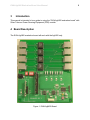
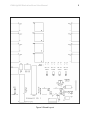
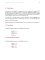
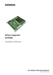
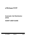
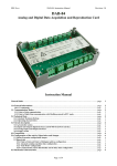
Silver
TELECOM
EVALAg6400 Evaluation
Board User Manual
Rev 2.0 – July 2011
EVALAg6400 Evaluation Board User Manual
1
1 Table of Contents
1 2 3 4 Table of Contents
1 Table of Figures
1 Introduction
2 Board Description
2 4.1 Input Power ......................................................................................................... 4 4.2 Data Inputs .......................................................................................................... 4 4.3 Data and Power Outputs ..................................................................................... 4 4.4 Ag6400 Power Supplies ...................................................................................... 6 4.5 Output Status LEDs............................................................................................. 6 4.6 Selection Switches .............................................................................................. 6 4.7 Software Interface ............................................................................................... 7 5 Equipment Required
8 6 Using the Board
9 6.1 Hardware Mode ................................................................................................... 9 6.2 Software Mode (on-board) .................................................................................. 9 6.3 Software Mode (external) .................................................................................. 10 2 Table of Figures
Figure 1: EVALAg6400 Board ......................................................................................... 2 Figure 2: Board Layout .................................................................................................... 3 Figure 3: Output Power Selector Links ............................................................................ 5 Figure 4: Selection Switches ........................................................................................... 6 Figure 5: I2C Control Circuit ............................................................................................ 7 Figure 6: Basic set-up ..................................................................................................... 8 Figure 7: External I2C Connections ............................................................................... 10 EVALAg6400 Evaluation Board User Manual
3
2
Introduction
This manual is intended to be a guide to using the “EVALAg6400 evaluation board” with
Silver Telecom Power Sourcing Equipment (PSE) module.
4 Board Description
The EVALAg6400 evaluation board will work with the Ag6400 only.
Figure 1: EVALAg6400 Board
EVALAg6400 Evaluation Board User Manual
Figure 2: Board Layout
3
EVALAg6400 Evaluation Board User Manual
4
4.1 Input Power
Input power for the Ag6400 is supplied through J11, which is a standard DC10
connector with a 2.5mm (Dia) centre pin. For use with IEEE802.3af Powered Devices
the input voltage can be between -45V to -57V and for IEEE802.3at PDs the voltage
can be between -50V and -57V. It is important that the power supply used has sufficient
current capability to handle all four ports at maximum load.
J11 centre pin is +Ve with respect to the outer connection. The EVALAg6400 board
does have a protection diode in series with the centre pin, to prevent damage if the
polarity is accidentally reversed.
When the Ag6400 is set in hardware mode this is the only power that the board needs.
4.2 Data Inputs
The EVALAg6400 board has four 10/100BASE-T data inputs: PORT 1 – J1
PORT 2 – J3
PORT 3 – J5
PORT 4 – J7
4.3 Data and Power Outputs
The EVALAg6400 board has four 10/100BASE-T outputs: PORT 1 – J2
PORT 2 – J4
PORT 3 – J6
PORT 4 – J8
EVALAg6400 Evaluation Board User Manual
5
Power can be applied to either the spare pairs or the data pairs on any port by setting
the position of the links LK1 to LK8, as shown below.
With jumper links positioned between the top and centre pins, the power will be supplied
on the DATA pairs.
With jumper links positioned between the centre and bottom pins, the power will be
supplied on the SPARE pairs.
Figure 3: Output Power Selector Links
It is important that these links are in the same position for each output port pair: –
LK1 & LK2 – Both on DATA or both on SPARE
LK3 & LK4 – Both on DATA or both on SPARE
LK5 & LK6 – Both on DATA or both on SPARE
LK7 & LK8 – Both on DATA or both on SPARE
It is not allowed to have one of the above pairs connected to the DATA pair and the
other connected to the SPARE pair (e.g. LK1 – DATA and LK2 – SPARE).
EVALAg6400 Evaluation Board User Manual
6
4.4 Ag6400 Power Supplies
The EVALAg6400 board only requires one power supply (as mentioned in Section 4.1),
but the AG6400 requires two supplies VCC and VEE. In addition to this the VCC supply to
the Ag6400 must power up before the VEE supply.
To make this easier the module U9 take the input voltage from J11 (-45V to -57V) and
generates the VCC supply rail (+3.3V). In addition to this is also connects the VCC rail to
the Ag6400 before switching the input supply from J11 to the VEE rail.
4.5 Output Status LEDs
When the Ag6400 is operating normally LEDs 4, 5, 6 and 7 will illuminate when power is
being applied to that port.
4.6 Selection Switches
SW2 connects to the MID and MODE pins (which have internal pull down resistors),
when the switch is closed the pin will be connected to VCC (Logic 1).
SW3 connects to the AD0 – AD3 I2C address inputs (which have internal pull up
resistors), when the switch is closed the pin will be connected to 0V (Logic 0).
Figure 4: Selection Switches
EVALAg6400 Evaluation Board User Manual
7
4.7 Software Interface
By default the EVALAg6400 board operates the Ag6400 in Hardware Mode. But it does
have the capably of operating the Ag6400 in Software Mode. To run the board in
Software Mode the circuit shown in Figure 5 needs to be powered from an isolated 5V
power supply. The circuit is designed to run from an isolated supply with opto-isolators
to demonstrate the example shown in the Ag6400 datasheet Figure 8.
The isolated 5V is supplied is connected through J9 Pin 1 is connected to GND and Pin 6 is connected to +5V
Figure 5: I2C Control Circuit
The EVALAg6400 can be used in software mode, either by using the on-board µcontroller (U1), or from an external controller via the I2C port on J9.
To use the on-board µ-controller links LK9 to LK11 must be fitted.
To use an external controller links LK10 and LK11 must be removed (isolating the onboard µ-controller from the I2C bus. LK9 connects SDI and SDO together for SDA, this
link can be removed if you want separate control lines.
When using the on-board µ-controller all switches on SW3 (AD0-3) must be closed.
EVALAg6400 Evaluation Board User Manual
8
5 Equipment Required
Figure 6 shows a simple set up using the EVALAg6400 board to power 4 x Ethernet
Cameras.
The equipment required: ¾ EVALAg6400
¾ Isolated -50V to -57V Power Supply (Optional 5V power supply for software
mode)
¾ PC
¾ Switch
¾ Ethernet Cameras
¾ CAT5e cables
Ag5100
PC
Data
Ethernet
Camera
Switch
Data & Power
Data
EVALAg6400
Ethernet
Camera
Data
Data
Data & Power
Data
Ethernet
Camera
Isolated Power Supply
(-50V to -57V)
Data & Power
Ethernet
Camera
Power Supply
(+5V)
Optional for Software Mode
Data & Power
Figure 6: Basic set-up
EVALAg6400 Evaluation Board User Manual
9
6 Using the Board
6.1 Hardware Mode
Using the set-up shown in Figure 6; data is connected to the EVALAg6400 board via a
switch connected to a PC.
With the EVALAg6400 set in hardware mode (SW2 - MODE switch Closed), it will
automatically detect equipment presenting a valid IEEE802.3at (or IEEE802.3af)
signature (and classification) connected to an output port.
Upon completion of a valid signature (and classification) the EVALAg6400 board will
add power to the data from the PC on that port. The corresponding LED on the
EVALAg6400 board will illuminate when power is being applied to a port.
6.2 Software Mode (on-board)
Using the set-up shown in Figure 6; data is connected to the EVALAg6400 board via a
switch connected to a PC.
With the EVALAg6400 set in software mode (SW2 - MODE switch Open), it is important
that the mode is set before the Ag6400 is powered up.
The (optional) 5V supply can be connected before or after the main (-45V to -57V)
supply is connected, it doesn’t matter which.
When both supplies have been connected, pressing (and releasing) the push switch
SW1 will enable the on-board µ-controller.
The first operation will be to check the mode of the Ag6400: If it is in software mode, then LED2 will be illuminated.
If it is in hardware mode, then LED1 will be illuminated.
If it is in software mode the µ-controller will continually monitor the status of each output
and respond accordingly.
If it is in hardware mode the µ-controller will do nothing and the Ag6400 will be if full
control of the outputs.
EVALAg6400 Evaluation Board User Manual
10
6.3 Software Mode (external)
Using the set-up shown in Figure 6; but this time J9 is connected to an external I2C bus.
Links LK10 and LK11 must be removed, to isolate the on-board µ-controller from the I2C
bus. If the external I2C bus uses SDA then LK9 must be fitted, but if the external I2C bus
uses SDI and SDO then the link LK9 must be removed.
Note: external power must also be provided through J9; primarily this is for the on-board opto-isolators;
but it will also power the on-board µ-controller (which is why it needs to be disconnected from the I2C
bus).
Data is connected to the EVALAg6400 board via a switch connected to a PC.
With the EVALAg6400 set in software mode (SW2 - MODE switch Open), it is important
that the mode is set before the Ag6400 is powered up.
Once the EVALAg6400 is powered, the Ag6400 is now controlled externally via the I2C
bus.
J9
6 - +5V
5 - /INT
4 - SDO
3 – SDI / SDA
2 - SCL
1 - GND
1
Figure 7: External I2C Connections