1
Sankyo
R
O B
O
T
I
C
S™
Buzz2 ADS User's Guide
CONTENTS
Preface
Safety
Installation and Configuration
Overview
Creating Applications
Debugging Applications
File Manager
Errors
Glossary
Technical Support
Communications Cable Wiring
Buzz - User’s Guide
Version 2.0
SC3000 Robot Systems
Federal Communications (FCC) Statement
Warning:
This equipment generates, uses, and can radiate radio frequency energy and if not
installed and used in accordance with the instructions manual, may cause interference to radio
communications. It has been tested and found to comply with the limits for a Class A computing
device pursuant to Subpart J of Part 15 of FCC Rules, which are designed to provide reasonable
protection against such interference when operated in a commercial environment. Operation of
this equipment in a residential area is likely to cause interference, in which case the user, at his
own expense, will be required to take whatever measures may be required to correct the
interference.
January 2001
Buzz User’s Guide,
Version 2.0.
Use this publication only for the purpose stated in the preface. This is the initial document for
“Buzz User's Guide, Version 2.0” software product, which supports all SSL/E Version 3.x and prior
commands. Buzz is an Application Development System (ADS), for the Sankyo SC3000 Series
Robot Controller, and is Windows based.
Changes are periodically made to the information herein. Refer to the last page of the Preface
Chapter to see a history of changes to this manual. Sankyo will make its best effort to report
any changes in subsequent revisions, or in Technical Newsletters.
The Sankyo “Buzz - Application Development System (ADS) for Windows”, and the “Sankyo
Structured Language/Enhanced” (SSL/E) are software products developed by Sankyo Seiki
Manufacturing Company, Ltd.
This publication, describing the use of the Sankyo software products referenced above, could
contain technical inaccuracies or typographical errors. Also, illustrations contained herein may
show prototype product. Your system configuration may differ slightly. Any questions concerning
the use of a Sankyo robotic product or on the contents of this document should be directed to any
of the Sankyo Robotics Divisions.
Refer to the Preface for information on the nearest Sankyo Robotics Division contact.
Windows, Windows 95, Windows 98, Windows NT, Windows 2000 and Windows ME are
registered trademarks of the Microsoft Corporation.
Copyright Sankyo Seiki Mfg. Co., Ltd. 1997, 2001
Sankyo is a trademark of Sankyo Seiki Mfg. Co., Ltd.
Buzz User's Guide – Version 2.0
CONTENTS
Preface ........................................................................................................................... ix
Audience ..................................................................................................................................................ix
About this Manual.....................................................................................................................................ix
Conventions used in this Manual ............................................................................................................. x
Related Publications ................................................................................................................................ x
Buzz Application Development System User’s Guide - History...............................................................xi
Safety............................................................................................................................ xiii
Installation Site Safety Precautions........................................................................................................ xiii
Operation Safety Procedures.................................................................................................................xiv
Safety Inspection.....................................................................................................................................xv
Safety Notices .........................................................................................................................................xv
Chapter 1 Installation and Configuration .................................................................. 1-1
Introducing Buzz Version 2.0 ..............................................................................................1-3
New features in Buzz Version 2.0 ......................................................................................................... 1-3
Changes in Buzz Version 2.0................................................................................................................ 1-3
System Requirements ........................................................................................................................... 1-3
Installing Buzz ......................................................................................................................1-4
Uninstalling Buzz................................................................................................................................... 1-4
Starting Buzz ......................................................................................................................................... 1-4
Configuring Buzz..................................................................................................................1-5
Configuring Buzz PC Communications ................................................................................................. 1-5
Configuring the Buzz Editor .................................................................................................................. 1-5
Configuring the Page Setup .................................................................................................................. 1-6
Configuring the Printer .......................................................................................................................... 1-6
The Buzz Display..................................................................................................................1-7
Online Mode .......................................................................................................................................... 1-7
Offline Mode .......................................................................................................................................... 1-8
Buzz Architecture.................................................................................................................1-8
Memory ................................................................................................................................................. 1-9
Jobs ....................................................................................................................................................... 1-9
JOBDEF.CFG File options............................................................................................................ 1-10
Tasks and Files ................................................................................................................................... 1-10
Source files ................................................................................................................................... 1-10
Robot Task ................................................................................................................................... 1-11
Peripheral Task............................................................................................................................. 1-11
System Task ................................................................................................................................. 1-11
Teaching Data Files...................................................................................................................... 1-11
Stepper Motor Task....................................................................................................................... 1-12
Debugging Tasks ................................................................................................................................ 1-12
Deploying Jobs and Tasks .................................................................................................................. 1-12
Deploy Job .................................................................................................................................... 1-12
Deploy Task .................................................................................................................................. 1-12
Copyright © Sankyo Robotics, 1997-2001
CONTENTS
i
SC3000 Robot Systems
Retrieving Jobs and Tasks.................................................................................................................. 1-13
Retrieve Job.................................................................................................................................. 1-13
Retrieve Task................................................................................................................................ 1-13
File Manager ....................................................................................................................................... 1-13
Errors and Troubleshooting................................................................................................................. 1-13
Wordfile.txt File.................................................................................................................................... 1-14
SSL/E Programming Samples ............................................................................................................ 1-14
Buzz Communications Cable Drawings .............................................................................................. 1-14
Chapter 2 Overview ..................................................................................................... 2-1
The Main Buzz Display.........................................................................................................2-3
Title Bar........................................................................................................................................... 2-3
Menu Bar ........................................................................................................................................ 2-3
Icon Bar........................................................................................................................................... 2-4
Text Window ................................................................................................................................... 2-4
Window Information line ................................................................................................................. 2-4
Basic Operations..................................................................................................................2-5
Open/Create A Job................................................................................................................................ 2-5
Create a Job.......................................................................................................................................... 2-6
Modify a Job .......................................................................................................................................... 2-6
Create/Modify a Task ............................................................................................................................ 2-6
Editing Source Files .............................................................................................................................. 2-6
Inserting characters ........................................................................................................................ 2-7
Overwriting characters.................................................................................................................... 2-7
Deleting characters......................................................................................................................... 2-7
Moving the cursor ........................................................................................................................... 2-7
Selecting text and lines................................................................................................................... 2-7
Searching text................................................................................................................................. 2-7
Compile or Build .................................................................................................................................... 2-8
Debugging Tasks .................................................................................................................................. 2-8
Deploying .............................................................................................................................................. 2-9
Deploy Job ...................................................................................................................................... 2-9
Deploy Task .................................................................................................................................... 2-9
Retrieving .............................................................................................................................................. 2-9
Retrieve Job.................................................................................................................................... 2-9
Retrieve Task.................................................................................................................................. 2-9
Chapter 3 Creating Applications................................................................................ 3-1
How this Chapter is organized ............................................................................................3-3
Creating Applications (Job).................................................................................................3-3
Create a Job.......................................................................................................................................... 3-4
Create Task Names .............................................................................................................................. 3-5
Open a Job............................................................................................................................................ 3-7
Open a Source File ............................................................................................................................... 3-8
The Window Menu.......................................................................................................................... 3-9
Editing Source Files...........................................................................................................3-10
ii
Buzz User’s Guide – Version 2.0
The Edit Menu ..................................................................................................................................... 3-10
Undo / Redo.................................................................................................................................. 3-11
Cut, Copy and Paste..................................................................................................................... 3-11
Delete............................................................................................................................................ 3-11
Insert File ...................................................................................................................................... 3-11
Find ............................................................................................................................................... 3-12
Replace......................................................................................................................................... 3-13
Goto Line ...................................................................................................................................... 3-13
Bookmark...................................................................................................................................... 3-14
Select All ....................................................................................................................................... 3-15
Match Brace.................................................................................................................................. 3-15
Display/Modify Templates............................................................................................................. 3-15
Insert Template............................................................................................................................. 3-15
To Upper Case / To Lower Case.................................................................................................. 3-16
Read Only..................................................................................................................................... 3-16
Compile and Build..............................................................................................................3-17
Compile Task ...................................................................................................................................... 3-17
Build all Tasks ..................................................................................................................................... 3-17
Deploy Task ........................................................................................................................................ 3-18
Deploy Job .......................................................................................................................................... 3-18
Displaying a Teach File......................................................................................................3-19
Saving Your Work ..............................................................................................................3-20
Save .................................................................................................................................................... 3-20
Save All ............................................................................................................................................... 3-20
Save As ............................................................................................................................................... 3-20
Close File ............................................................................................................................................ 3-21
Printing Your Files .............................................................................................................3-21
Print active file .............................................................................................................................. 3-21
Print Preview................................................................................................................................. 3-23
The Next Step .....................................................................................................................3-23
Chapter 4 Debugging Applications............................................................................ 4-1
Debugging ............................................................................................................................4-3
Debug a Currently Running Job/Task ................................................................................................... 4-3
Start Debugging .................................................................................................................................... 4-6
Set the Robot Arm Speed ..................................................................................................................... 4-8
The Debug Menu................................................................................................................................... 4-9
Edit Task List ................................................................................................................................ 4-10
System I/O Enabled...................................................................................................................... 4-10
Go ................................................................................................................................................. 4-10
Stop Debugging ............................................................................................................................ 4-12
Step............................................................................................................................................... 4-12
Start .............................................................................................................................................. 4-12
Resume......................................................................................................................................... 4-13
Step Stop ...................................................................................................................................... 4-13
Hold............................................................................................................................................... 4-13
CONTENTS
iii
SC3000 Robot Systems
Cycle Stop .................................................................................................................................... 4-13
Add Watch .................................................................................................................................... 4-14
Watch Simple variables............................................................................................................. 4-15
Watch String variables .............................................................................................................. 4-15
Watch Array variables ............................................................................................................... 4-16
Watch Position variables ........................................................................................................... 4-16
Watch Current Position ............................................................................................................. 4-17
Quick Watch ................................................................................................................................. 4-18
Quick Watch Simple variables .................................................................................................. 4-18
Quick Watch String variables .................................................................................................... 4-19
Quick Watch Array variables ..................................................................................................... 4-20
Delete Watch ................................................................................................................................ 4-21
Close Watch Window.................................................................................................................... 4-21
Toggle Breakpoint......................................................................................................................... 4-21
Clear Breakpoints ......................................................................................................................... 4-21
Error Reset ................................................................................................................................... 4-21
Displaying a Teach File ....................................................................................................................... 4-22
Deploy the Job .................................................................................................................................... 4-23
Deploy the Task .................................................................................................................................. 4-23
Chapter 5 The File Manager........................................................................................ 5-1
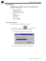
The File Manager ..................................................................................................................5-3
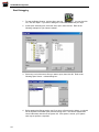
Starting the File Manager ...................................................................................................................... 5-3
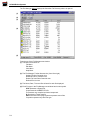
File Manager Functions .......................................................................................................5-5
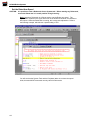
Upload File from Controller ................................................................................................................... 5-5
Download File to Controller ................................................................................................................... 5-6
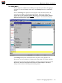
Delete Files ........................................................................................................................................... 5-6
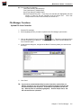
Refresh File List .................................................................................................................................... 5-7
Display System Files ............................................................................................................................. 5-7
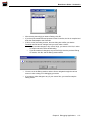
Edit Functions........................................................................................................................................ 5-8
Select All ......................................................................................................................................... 5-8
Invert Selection ............................................................................................................................... 5-8
Arrange File Display .............................................................................................................................. 5-8
Close the File Manager ......................................................................................................................... 5-8
Chapter 6 Errors .......................................................................................................... 6-1
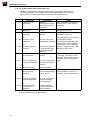
Error Classification ..............................................................................................................6-5
Buzz Error Messages ...........................................................................................................6-6
Types of Error Messages ...................................................................................................................... 6-6
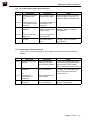
1.1 ADS Communication Information (Error) ....................................................................................... 6-7
1.1.1 The Controller notified of an error.......................................................................................... 6-7
1.1.2 The communication driver detected an error........................................................................ 6-8
1.1.2 The communication driver detected an error........................................................................ 6-9
1.1.3 An error with the PC was detected ....................................................................................... 6-9
1.1.4 An error was caused by mis-operation ............................................................................... 6-10
1.1.5 An error description was caused in the SSL program ........................................................ 6-10
iv
Buzz User’s Guide – Version 2.0
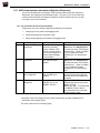
1.2.1 ADS Communication Information (Rejection Response) .......................................................... 6-11
1.2.1 The Controller cannot accept commands........................................................................... 6-11
1.2.1.5 The Controller cannot accept commands (continued) .................................................... 6-12
1.2.1.13 The Controller cannot accept commands (continued) .................................................. 6-13
1.2.1.25 The Controller cannot accept commands (continued) .................................................. 6-14
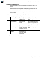
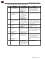
1.2.2 Specific Command Errors ......................................................................................................... 6-15
1.2.2.1 Command numbers: Start = 1, Stop = 2, Error Reset = 3 .............................................. 6-15
1.2.2.5 Command numbers: Start = 1, Stop = 2, Error Reset = 3 .............................................. 6-16
1.2.2.15 Command numbers: Upload = 7, Upload data = 9....................................................... 6-17
1.2.2.24 Command number: Download = 8................................................................................ 6-18
1.2.2.35 Command number: Download = 8................................................................................ 6-19
1.2.2.39 Command number: ADS internal = FF ......................................................................... 6-20
1.2.2.45 Command number: ADS internal = FE......................................................................... 6-21
1.2.2.53 Command number: ADS internal = Any other command ............................................. 6-22
1.2.2.60 Command number: ADS internal = Any other command ............................................. 6-23
1.2.2.72 Command number: ADS internal = Any other command ............................................. 6-24
2.1 Miscellaneous Error Messages .................................................................................................... 6-25
2.1.1 Miscellaneous Error Text Message .................................................................................... 6-25
2.1.12 Miscellaneous Error Text Message .................................................................................. 6-26
Compiler Error Messages ..................................................................................................6-27
“Cannot assign to teaching position data" .................................................................................... 6-28
“Cannot create object file : ????.TSK" ......................................................................................... 6-28
“Cannot create error list file : ????.TSK" ...................................................................................... 6-28
“Cannot declare teaching position data as a local variable"......................................................... 6-28
“Cannot initialize local variables" .................................................................................................. 6-28
“Cannot initialize teaching position data"...................................................................................... 6-28
“Cannot link more than 8 files"...................................................................................................... 6-28
“Cannot open source file” ............................................................................................................. 6-28
“Duplicate CASE value" ................................................................................................................ 6-29
“Illegal array definition" ................................................................................................................. 6-29
“Illegal assignment statement"...................................................................................................... 6-29
“Illegal character" .......................................................................................................................... 6-29
“Illegal character constant" ........................................................................................................... 6-29
“Illegal definition statement".......................................................................................................... 6-29
“Illegal expression"........................................................................................................................ 6-30
“Illegal initializing" ......................................................................................................................... 6-30
“Illegal statement" ......................................................................................................................... 6-30
“Illegal symbol for constant".......................................................................................................... 6-30
“Illegal symbol use"....................................................................................................................... 6-30
“Integer expected for subscript of array" ...................................................................................... 6-30
“Integral type constant expected for case value".......................................................................... 6-31
“Label redefined : xxxxxxxx" ......................................................................................................... 6-31
“Missing CASE value"................................................................................................................... 6-31
“Missing colon for CASE label"..................................................................................................... 6-31
“Missing 'END'" ............................................................................................................................. 6-31
“Missing label in 'GOTO'/'CYCLE' statement" .............................................................................. 6-31
“Missing semicolon" ...................................................................................................................... 6-32
CONTENTS
v
SC3000 Robot Systems
“Missing {" ..................................................................................................................................... 6-32
“Missing }" ..................................................................................................................................... 6-32
“Missing [ ]" ................................................................................................................................... 6-32
“Missing (" ..................................................................................................................................... 6-32
“Missing )" ..................................................................................................................................... 6-32
“Missing */".................................................................................................................................... 6-32
“Only position data or position qualifier can be declared" ............................................................ 6-32
“Position qualifier:<,> wasn't closed" ............................................................................................ 6-33
“Recursive-function-call hasn't been supported" .......................................................................... 6-33
“Redefinition : xxxxxxxx"............................................................................................................... 6-33
“String too long" ............................................................................................................................ 6-33
“Subscript out of range" ................................................................................................................ 6-33
“Symbol expected"........................................................................................................................ 6-33
“Symbol of variable except 'position type' expected as argument" .............................................. 6-33
“The number of position qualifier: <,> wasn't balanced"............................................................... 6-34
“The number of {,} was unbalanced" ............................................................................................ 6-34
“The number of [,] was unbalanced"............................................................................................. 6-34
“The number of (,) has been unbalanced" .................................................................................... 6-34
“Too big case value" ..................................................................................................................... 6-34
“Too complex expression" ............................................................................................................ 6-34
“Too deep nest" ............................................................................................................................ 6-34
“Too few or too many actual arguments"...................................................................................... 6-35
“Too many arguments for function declaration"............................................................................ 6-35
“Too many elements in position qualifier"..................................................................................... 6-35
“Too many if/while statement nested." ......................................................................................... 6-35
“Undefined function name" ........................................................................................................... 6-35
“Undefined label : xxxxxxxx"......................................................................................................... 6-35
“Unknown function name : xxxxxxxx" ........................................................................................... 6-36
“Unknown variable name : xxxxxxxx" ........................................................................................... 6-36
“Value of constant out of range" ................................................................................................... 6-36
"',' or ' )' should follow ' >'"............................................................................................................. 6-36
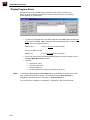
Displaying Errors ...............................................................................................................6-37
Display Program Errors .....................................................................................................6-38
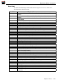
Error Code........................................................................................................................................... 6-39
Error Data - Error Code 1, 2 or 3 Chart.............................................................................................. 6-40
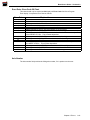
Error Data - Error Code 26 Chart ........................................................................................................ 6-41
Axis Number........................................................................................................................................ 6-41
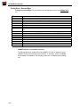
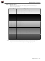
Display System Errors .......................................................................................................6-42
Config Error - First byte ....................................................................................................................... 6-43
Config Error - Second Byte ................................................................................................................. 6-44
ABS Error Detail – First Byte............................................................................................................... 6-45
ABS Error Detail – Bytes 2 - 9............................................................................................................. 6-45
Field 9 (Realtime Error) ...................................................................................................................... 6-46
Field 10 (Realtime Error).................................................................................................................... 6-47
Field 11 (Realtime Error).................................................................................................................... 6-48
Field 12 (Realtime Error).................................................................................................................... 6-48
Field 13 (Realtime Error).................................................................................................................... 6-49
vi
Buzz User’s Guide – Version 2.0
Field 14 (Realtime Error).................................................................................................................... 6-49
Field 15 (Realtime Error).................................................................................................................... 6-50
Field 15A (RISC Error) ....................................................................................................................... 6-51
System Error ....................................................................................................................................... 6-51
Hardware servo off .............................................................................................................................. 6-51
Other Information ................................................................................................................................ 6-52
Backup .......................................................................................................................................... 6-52
Error Record # .............................................................................................................................. 6-52
Power on Count ............................................................................................................................ 6-52
Elapsed Time................................................................................................................................ 6-52
Initial.............................................................................................................................................. 6-52
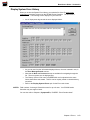
Display System Error History ............................................................................................6-53
Glossary .......................................................................................................................... 1
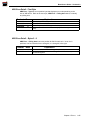
Appendix A Technical Support ..................................................................................... 1
Technical Support - USA and the Americas ............................................................................................ 1
Technical Support - Europe ..................................................................................................................... 2
Technical Support – Japan/Asia .............................................................................................................. 2
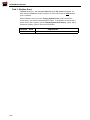
Appendix B Buzz Communications Cable Wiring ....................................................... 1
ADS Port Cable Wiring............................................................................................................................. 1
CONTENTS
vii
SC3000 Robot Systems
This page left blank intentionally
viii
Buzz User’s Guide – Version 2.0
Preface
Audience
This manual is intended for use by Robot application programmers. For safety
reasons, users of this manual are expected to be familiar with the general operation of
automation equipment. The Safety chapter, which immediately follows, should be read
and understood in its entirety before any operation begins.
About this Manual
This manual provides information on the Buzz software product, Version 2.0. This
software product is an Application Development System (ADS), that supports the
writing, compiling or building, editing, monitoring and debugging of the user application
programs for the Sankyo SC3000 series Robot Controllers.
The subject matter in this manual is divided into the following chapters:
•
Preface, This chapter.
•
Safety, Safety guidelines are presented.
•
Chapter 1, "Installation and Configuration", describes the installation, configuration
and architecture of the Buzz software package.
•
Chapter 2, "Overview", describes the basic operations of the Buzz software
package.
•
Chapter 3, "Creating Applications", describes the work with application files, from
creating source files through the compile or build phase.
•
Chapter 4, "Debugging Applications", describes the debugging features of the Buzz
software package.
•
Chapter 5, "The File Manager", describes using the Buzz - File Manager. This
feature of Buzz manages all Controller files.
•
Chapter 6, “Errors”, describes the various errors that can occur while using the Buzz
software package.
•
Glossary, provides definitions of the special terms used in this manual.
•
Appendix A, “Technical Support”, describes how to contact Sankyo Robotics
Technical Support.
•
Appendix B, “Buzz Communication Cable Wiring”, describes the wiring of the ADS
Port cable.
Copyright © Sankyo Robotics, 1997-2001
Preface
ix
SC3000 Robot Systems
Conventions used in this Manual
The Buzz Application Development System, is known throughout this manual as “Buzz".
The SC3000 Robot Controller is known throughout this manual as "Controller".
The Manipulator, or, the Industrial Robot, is known throughout this manual as "Robot".
Manip.-power, Servo power and Robot power are the same, power applied to the Robot
drive motors.
Related Publications
Related publications and sales assistance can be obtained directly from Sankyo Robotics:
Sankyo Robotics
1001-D Broken Sound Parkway NW
Boca Raton, FL 33487
USA
AES Motomation GmbH
Nikolaus-Otto-Str. 8
D-40670 Meerbusch
Germany
561-998-9775
561-998-9778 FAX
(49) 2159-4088
(49) 2159-3872 FAX
Sankyo Seiki Mfg. Co., Ltd.
Machine Tools Division
17-2, 1 Chome, Shinbashi
Minato-Ku, Tokyo, 105
Japan
(81) 3-3508-1156
(81) 3-3502-1353 FAX
[email protected]
See Note
Note:
The Sankyo office in Tokyo, Japan, may not provide all related publications.
Related publications are:
•
Sankyo CCR-M Series Hardware Manual.
•
Sankyo SCARA Series Hardware Manual.
•
•
SC3000 Series Installation and Specifications Manual.
•
(Formerly, Sankyo SR8437/SR8438 and CCR–M Series Site Preparation,
Installation and Specifications manual.)
•
Sankyo SSL/E Language Reference Manual.
•
Sankyo Robot Systems User's Guide.
NOTE:
x
(Formerly, Sankyo SR8437/SR8438 Series Hardware Manual.)
The Buzz Version 1 Manual is: Buzz – Application Development System User's Guide.
Buzz User’s Guide – Version 2.0
Buzz User’s Guide – Version 2, History
Version 2.00 - 01/01
This is the first version for Buzz software version 2.0. The Buzz software product has
been re-written, enhanced and contains new Maintenance functions.
Preface
xi
SC3000 Robot Systems
This page left blank intentionally
xii
Buzz User’s Guide – Version 2.0
Safety
Safety cannot be overemphasized when operating any Robot System, including the
Sankyo Robot Systems. Before any operation begins on these systems, be sure to
read and understand the following safety notices:
Installation Site Safety Precautions
Be familiar with the American National Standards Institute/Robotic Industries
Association (ANSI/RIA) safety standard R15.06-1999. As of July, 2000, this is the
latest published safety standards for Robotic systems.
•
Ensure compliance with all local, state and national safety and electrical codes for the
installation and operation of the Sankyo Robot System.
•
Observe the power and grounding instructions given in the Sankyo SR8437/SR8438
and CCR-M Series Site Preparation, Installation and Specifications Manual, (prior
version), or the Sankyo SC3000 Series Installation and Specifications Manual
(current version).
•
The Robot System should not be installed in an explosive atmosphere.
•
Fire extinguishers should be located within easy access of the Robot System.
•
The following recommendations apply to any Robot System:
•
Install intrusion devices or safety mats around the Robot to stop Robot motion if the work
area is penetrated.
•
Install additional Emergency Stop switches for feeders and other fixtures to stop the
Robot System’s motion, whenever these fixtures are serviced.
•
Install an Emergency Stop switch in any mounting enclosure, to simultaneously turn
off the Robot Controller and stop Robot motion.
Copyright © Sankyo Robotics, 1997-2001
Safety
xiii
SC3000 Robot Systems
Operation Safety Procedures
Safety precautions should always be observed when operating Robot Systems. As with
any electromechanical machine or component, unpredictable failures could occur while
the system is in operation.
CAUTION: Whenever possible, electrical power and air pressure to the Robot System should be
turned off and disconnected before any penetration of the Robot work area begins. If it
is not possible to disconnect power and air pressure due to the nature of the operation,
extreme caution should be observed.
If you must penetrate the work area without disconnecting electrical power and air
pressure, press the Emergency Stop push-button on the Controller front panel, or the
remote cable, to remove power to the Robot. Then place a "DO NOT OPERATE" sign
near the front of the SC3000 Robot Controller, and if possible, carry the remote cable
into the work area with you, to ensure that you remain in control of Robot power.
NOTE:
xiv
Pressing the Emergency Stop push-button on the Controller or the remote cable does not
remove potential dangers created by other devices in the work area. You should
ensure that all potentially hazardous devices are powered-off or otherwise secured
before penetrating the work area.
•
The Robot arm moves with great force and speed. Therefore, serious injury could result
from failure to observe caution when the work area is penetrated. As stated above,
power and air pressure to the Robot should be turned off and disconnected first,
whenever possible.
•
Before reconnecting power and air pressure, always check the Robot work area for
adequate clearance. Be absolutely certain no one is in the Robot work area.
•
All personnel working with the system must have, at minimum, instruction and practice in
the use of the safety devices on the system. Safety procedures should be thoroughly
reviewed to ensure complete understanding.
•
Observe safe access routes to and from the Robot.
•
Utilize signs around the Robot and at power disconnects to alert others to potential
hazards.
Buzz User’s Guide – Version 2.0
Safety Inspection
Before you service the application on the Robot System, you should perform the
following inspection. Verify that:
•
Pressing the Emergency Stop push-button on the Controller front panel, or on the
remote cable, causes Robot power to drop immediately.
•
The Power switch located on the Controller front panel will drop all power to the SC3000
Robot Controller and Robot.
•
The Power indicator located on the Controller front panel is on when power is applied to
the SC3000 Robot Controller.
•
Another person familiar with power-off controls should be in the immediate vicinity to turn
the power off should it become necessary.
Safety Notices
This document may contain the following safety notices:
CAUTION: This notice advises of a condition that could present a potential hazard where serious
personal injury, except as defined for a DANGER notice, is possible unless care is
exercised
NOTE:
This notice advises of information that is important to consider during this particular step
or action.
Safety
xv
SC3000 Robot Systems
This page left blank intentionally
xvi
Buzz User’s Guide – Version 2.0
Chapter 1 Installation and Configuration
CONTENTS
Introducing Buzz Version 2.0 ..............................................................................................1-3
New features in Buzz Version 2.0 ......................................................................................................... 1-3
Changes in Buzz Version 2.0................................................................................................................ 1-3
System Requirements ........................................................................................................................... 1-3
Installing Buzz ......................................................................................................................1-4
Uninstalling Buzz................................................................................................................................... 1-4
Starting Buzz ......................................................................................................................................... 1-4
Configuring Buzz..................................................................................................................1-5
Configuring Buzz PC Communications ................................................................................................. 1-5
Configuring the Buzz Editor .................................................................................................................. 1-5
Configuring the Page Setup .................................................................................................................. 1-6
Configuring the Printer .......................................................................................................................... 1-6
The Buzz Display..................................................................................................................1-7
Online Mode .......................................................................................................................................... 1-7
Offline Mode .......................................................................................................................................... 1-8
Buzz Architecture.................................................................................................................1-8
Memory ................................................................................................................................................. 1-9
Jobs ....................................................................................................................................................... 1-9
JOBDEF.CFG File options............................................................................................................ 1-10
Tasks and Files ................................................................................................................................... 1-10
Source files ................................................................................................................................... 1-10
Robot Task ................................................................................................................................... 1-11
Peripheral Task............................................................................................................................. 1-11
System Task ................................................................................................................................. 1-11
Teaching Data Files...................................................................................................................... 1-11
Stepper Motor Task.........
...................................................................................................... 1-12
Debugging Tasks ................................................................................................................................ 1-12
Deploying Jobs and Tasks .................................................................................................................. 1-12
Deploy Job .................................................................................................................................... 1-12
Deploy Task .................................................................................................................................. 1-12
Retrieving Jobs and Tasks.................................................................................................................. 1-13
Retrieve Job.................................................................................................................................. 1-13
Retrieve Task................................................................................................................................ 1-13
File Manager ....................................................................................................................................... 1-13
Errors and Troubleshooting................................................................................................................. 1-13
Wordfile.txt File.................................................................................................................................... 1-14
SSL/E Programming Samples ............................................................................................................ 1-14
Buzz Communications Cable Drawings .............................................................................................. 1-14
Copyright © Sankyo Robotics, 1997-2001
Chapter 1 Installation and Configuration
1-1
SC3000 Robot Systems
This page left blank intentionally
1-2
Buzz User’s Guide – Version 2.0
Introducing Buzz Version 2.0
New features in Buzz Version 2.0
•
Able to Debug a currently running application, without having to restart the
application from the beginning.
•
Color coding for user defined functions. See "Configuring the Buzz Editor", found
later in this chapter.
•
Dynamic changing of the communications port. See "Configuring Buzz PC
Communications", found later in this chapter.
•
Implement error decode screens for program and systems errors. Refer to Chapter
6, "Errors".
•
Retrieval of the "Error History data" from the Controller. Refer to Chapter 6, "Errors".
•
SSL/E programming samples included, in the \Buzz2\Samples folder.
•
Watch variables – added support for arrays and strings. Refer to Chapter 4,
"Debugging Applications".
•
Stand-alone utility program (SC3INST.EXE) for automatically updating the Controller
System software.
Changes in Buzz Version 2.0
•
Download job/task is now an option for Debug mode, if the files on the Controller and
PC match. Refer to "Starting Buzz", found later in this chapter.
•
"Editor Settings" has changed to "Preferences" on the File menu. All the Buzz
configuration tasks start by clicking on Preferences.
•
Updated the Buzz Help file.
•
Enhanced the tool bar icons.
•
Improved the Retrieve Job and Retrieve Task functions, now more user friendly.
System Requirements
PC Requirements
•
Buzz is supported on the following PC Windows system software platforms:
•
*Windows 95 – OSR2.
•
Windows 98.
•
Windows NT (Version 4.0 or later with Service pack 6.0 or later).
• Windows 2000.
*Windows 95 is not supported for 80486 processor types (and prior), and their
equivalent processor types, or, prior to the OSR2 release.
•
200 MHz Processor or faster.
•
SVGA Display resolution of 800 X 600 and higher.
•
32 MB Ram.
•
Available 16 MB hard disk space.
SC3000 Controller Requirements
•
SC3000 series Controllers, model 030 and 300.
•
SC3000 system software version 103.15 or later.
Chapter 1 Installation and Configuration
1-3
SC3000 Robot Systems
Installing Buzz
WARNING: If you have BuzzX Version 1.x or BuzzX Version 2.0 BETA installed
on this PC, please contact Sankyo Technical Support before Installing this
product:
1-561-998-9775, or [email protected].
NOTE:
If you have a Windows NT or a Windows 2000 system, a person with “Administrative
privileges” must install the Buzz software product.
1.
If you have a previous version of Buzz already installed, uninstall that version before
proceeding. Refer to the topic, ”Uninstalling Buzz”, found later in this chapter.
2.
Ensure that a supported PC system software version is installed on your Buzz PC.
Refer to the prior topic.
3.
Place the Buzz master CD into your PC drive.
4.
From the Desktop, click the Start button, select Settings, then click Control Panel.
5.
From the Control Panel group, click Add/Remove Programs, then Install, and follow the
prompts.
6.
The Buzz files can be installed in the folder of your choice, or you can choose the
default folder.
7.
A “Samples” folder in also installed which includes several SSL/E programming
examples.
Uninstalling Buzz
1.
From the Desktop, click the Start button, select Settings, then click Control Panel.
2.
From the Control Panel group, double click Add/Remove Programs, and follow the
prompts.
3.
Buzz software is removed from your PC. You may now re-install Buzz.
Starting Buzz
1.
Attach the Sankyo supplied ADS communications cable from the Buzz PC to the
Controller ADS port. Buzz Version 2.0 defaults to the PC COM1 port.
2.
From the Desktop, click the Buzz Ver 2.0 icon. If you are successful in communicating
with the SC3000 series Controller, skip to the next topic, "Configuring Buzz".
3.
There are three scenarios for Buzz Version 2.0 communications not working:
1. The Controller is powered off, or the Buzz PC cable is not attached to the
Controller. Check the Buzz PC cable at both ends.
2. Wrong port configured, the Buzz PC cable is not attached to the configured PC
COM port, or the wrong cable is installed.
1-4
•
Check your PC COMM port configuration. Refer to "Configuring Buzz PC
communications", found later in this chapter.
•
Ensure that the Buzz PC cable is attached to the configured PC COMM port.
•
Refer to Appendix A, topic, "ADS port cable wiring" and ensure you have the
correct cable
Buzz User’s Guide – Version 2.0
3. Another device owns the configured COM port. Make sure the configured
COMM port is not in use.
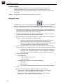
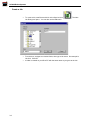
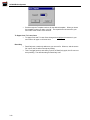
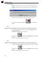
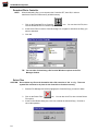
4.
If you are not connected to a Controller and want to work at your Desktop, you will see
the following pop-up.
5.
Click on "Work Offline" and continue with the next topic, "Configuring Buzz".
Configuring Buzz
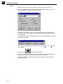
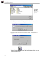
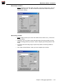
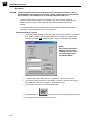
Configuring Buzz PC Communications
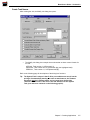
After starting Buzz, configure the Buzz communications port:
1.
Click on File, then Preferences.
2.
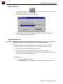
Select your Communication Port number from the Editor Setup dialog box, Com1 - Com9.
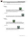
3.
If you are changing your comm port, a pop-up reminds you that this change is dynamic.
4.
Click "Yes" to dynamically change your communications port.
5.
The Communications port is configured. Continue with the next topic, if necessary.
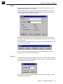
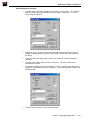
Configuring the Buzz Editor
NOTE:
To configure your character font, you must have a source file open. If you have a source
file to open, skip steps 1 through 4, go to step 5. If you do not have a source file to open,
you can open a Buzz sample source file by performing steps 1 through 4.
1.
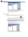
Start Buzz. Click File, then Open File.
2.
Navigate to where you installed Buzz. Under the Buzz2 folder is a folder called
\Samples.
3.
Open the Samples folder and click on any sample source file.
4.
Proceed to configure your Buzz preferences, skip to step 6.
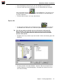
5.
Click on File, then Preferences.
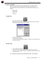
6.
From the Editor Setup dialog box, select your SSL/E source file colors. This step maps
the commands and functions in the Wordfile.txt file to the source file colors. You can
also color code your own user functions. Refer to the topic, “Wordfile.txt File", found
later in this chapter.
Chapter 1 Installation and Configuration
1-5
SC3000 Robot Systems
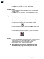
7.
Configure your page tabs from the Set Tabs… button.
8.
The default font is courier. To change your font, click the Select Editor Font… button,
and choose another font. (You must have a source file open.)
9.
Click OK when finished.
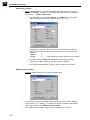
Configuring the Page Setup
NOTE:
To configure your Page setup, you must have a source file open. If you do not have a
source file to open, refer to steps 1 through 4 of "Configuring the Editor setup", on the
previous page, to open a source file.
1.
Start Buzz, if it is not already started. Click on File, then Page Setup.
2.
From the Page Setup dialog box, you are prompted for the margin dimensions.
3.
Select Inch (inches) or mm (millimeters), for your margin dimensions.
4.
Click OK. The Page Setup is reflected on any printed output.
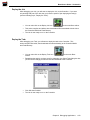
Configuring the Printer
1-6
1.
Start Buzz, if it is not already started. Click on File, then Print Setup.
2.
Select your printer from the Print Setup dialog box.
3.
You can also configure your Printer properties from this dialog box.
4.
Click OK when finished.
Buzz User’s Guide – Version 2.0
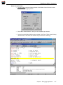
The Buzz Display
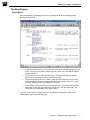
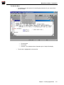
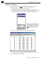
Online Mode
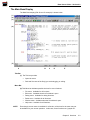
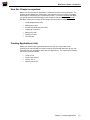
After starting Buzz, and opening a source file, a display similar to the following graphic
appears on the Buzz PC:
•
In the Sankyo Buzz title bar, you can see the name of the Job that was opened, Jobmotor. The source file name is “Palletizing.SSL”, and is one of the SSL/E samples
shipped with Buzz.
•
The second line from the top is the Menu bar. This Menu bar adds and deletes
Menu choices depending on the current Buzz operation.
•
The third line down is the Icon Toolbar. Simply point the mouse to any icon and a
small information pop-up box displays with the name (function) of the icon. These
icons are shortcuts to the various Menu bar functions.
•
At the bottom of the text window is an Information line. This line contains pertinent
information on the data presented in the text window. The data displayed in the
information line is dependent on the Buzz function.
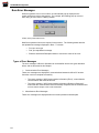
If you are not successful in starting Buzz, you are placed in Offline Mode. Refer to the
“Offline Mode” topic on the following page.
Chapter 1 Installation and Configuration
1-7
SC3000 Robot Systems
Offline Mode
When you are not successful in starting a Buzz session with the SC3000 series
Controller, or you are running Buzz at your desktop (without a Controller), you are given
the option of working offline, or exiting the Buzz application.
There are three scenarios for Buzz Version 2.0 communications not working:
1.
The Controller is powered off, or the Buzz PC cable is not attached to the
Controller. Check the Buzz PC cable at both ends.
2.
Wrong port configured, the Buzz PC cable is not attached to the configured PC
COM port, or the wrong cable is installed.
•
Check your PC COMM port configuration. Refer to "Configuring Buzz PC
communications", found later in this chapter.
•
Ensure that the Buzz PC cable is attached to the configured PC COMM port.
•
3.
Refer to Appendix A, topic, "ADS port cable wiring" and ensure you have the
correct cable
Another device owns the configured COM port. Make sure the configured COMM
port is not in use.
If you want to work at your Desktop, or without a Controller, click on the Work Offline
button.
Buzz Architecture
Buzz is an “Application Development System” that is used with the Sankyo SC3000
series Robot Systems. The following terms are discussed on the following pages with
regard to their role in the Buzz architecture.
1-8
•
Memory.
•
Jobs, discussed in detail in Chapter 3.
•
JOBDEF.CFG file, discussed in detail in Chapter 3.
•
Tasks and Files.
•
Debugging Tasks, discussed in detail in Chapter 4.
•
Deploying Jobs and Tasks.
•
Retrieving Jobs and Tasks.
Buzz User’s Guide – Version 2.0
•
File Manager, discussed in detail in Chapter 5.
•
Troubleshooting Errors, discussed in detail in Chapter 6.
•
Wordfile.txt file.
•
SSL/E Programming Samples.
•
Buzz Version 2 Cable Drawing, refer to Appendix B.
Memory
Two kinds of Memory exist in the SC3000 Series Controllers:
1.
MAIN, also called executable memory, – up to 1024 KB (1 MB).
2.
Flash - 1024 KB, (1 MB) file and data storage.
RAM memory on the SC3000 Controller uses DRAM technology and is the MAIN or
executable memory. It contains the contents of the current Job and all its associated
tasks. This is determined from the contents of the JOBDEF.CFG file. RAM is battery
backed and also contains the executable system software files.
Flash memory on the Controller mimics a hard file or disk drive, but is much faster.
When the Controller is powered on, the JOBDEF.CFG file in Flash Memory is analyzed
and if the JOBDEF in Flash Memory is different from the one stored in RAM, the
JOBDEF.CFG file and all its associated files are transferred from Flash Memory to
RAM. Flash Memory also stores the necessary Controller system software files.
Jobs
A Job, as defined in Buzz, is a collection of files (source, object, teaching data, etc.) that
make up a Robot application. When a Job is created in Buzz, a folder is created on
your Buzz PC with the same name you gave to the Job. Each of the file names you
provide in the Create Job dialog box becomes a file in the newly created PC folder.
Several file types are available within a Job:
•
Source file - One mandatory, up to eight for each task (object file).
•
Robot Task - One mandatory, task numbers 1 through 4. A Stepper motor task, task
numbers 2 through 4, is considered a Robot task.
•
Peripheral Task - Optional, up to 8 total, task numbers 11 through 18.
•
System Task - Optional, one only, task number 255.
•
Teach data file – Only required for teach point (TPOSITION) variables in your Robot
task(s). Teach data files are associated with their Robot or Stepper motor tasks,
and do not have task numbers.
Once the Create Job dialog box is completed, a JOBDEF.CFG file is created. This
critical user file contains the names of all the files that make up the Job you just
created. If the Job is later modified, the JOBDEF.CFG file is updated for you.
Refer to the sample JOBDEF.CFG file on the following page.
Chapter 1 Installation and Configuration
1-9
SC3000 Robot Systems
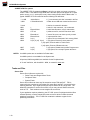
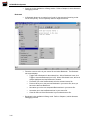
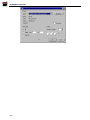
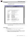
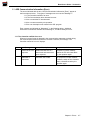
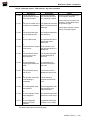
JOBDEF.CFG File options
The JOBDEF.CFG file created with Buzz, is built for you when you issue a request to
create a JOB. Lines #005 through #008 define the task options and appear as a 0 (task
option not set), or a 1, (task option is set), when viewing the file with the Buzz editor. A
typical JOBDEF.CFG robot task file has the following line definitions:
* % JOB
* #001
Job definition,
C:\Buzz\WorkcellA
% task
#001
#002
#003
#003
#004
#005
#006
// this line is created for all tasks.
1
// task #, in this case task, 1 is a robot task.
Eboard12.dat
// teach data file name, only for robot tasks.
UTY.ssl
// pallet source file, must be first when used.
Eboardb.ssl
// source file name, can have up to 8 per task.
Eboard12.tsk
// output task file name.
0 (n1)
// option, Do not reload task if b/u memory failed.
0 (n2) 0 (n3) 0 (n4)
// (n2) option, Execute if servo power off.
// (n3) option, Execute while in Teach mode.
// (n4) option, Execute if Robot task error.
0 (n5)
// (n5) option, Disable resume after Program error.
0 (n6)
// (n6) option, Do not stop if System task error.
#007
#008
// (*) is a comment, this line is created in all files.
// folder where JOB was created and/or stored.
NOTES: Line #006 options are not available for Robot tasks.
Line #008 option is not available for the System task.
All options, #005 though #008, are available for the Peripheral task.
A “% task” definition, with lines #001 - #008, is created for each task
Tasks and Files
Source files
Source files in Buzz are required for:
• Robot Tasks and Stepper Motor Tasks
•
Peripheral Tasks
• System Tasks
Source files in Buzz can have any file extension except TSK and DAT. TSK is
reserved for the compiled or built (object file) output task, and DAT is reserved for the
teaching data files. Up to eight source files may be defined for any single task. The
default file extension for source files is SSL, but you may choose another extension,
such as TXT. Task numbers are not assigned to source files.
If your application requires palletizing, the UTY.SSL source file (shipped with the Buzz
software product), must be placed before the source file which contains the actual
palletizing commands. The UTY.SSL file contains the software support for the
palletizing commands.
1-10
Buzz User’s Guide – Version 2.0
Robot Task
Only one Robot task is permitted for each Robot or Stepper motor attached to the
Controller. Up to eight source files may be defined for a single Robot task. A number
is assigned to each Robot task (1 - 4) which coincides to the Robot(s) or Stepper
motor(s) attached to the Controller. For example, if a Robot and a stepper motor were
attached to a single Controller, Task 1 (Robot) and Task 2 (Stepper motor) are valid.
Tasks 3 and 4 are invalid, since those Robots/stepper motors are not attached to the
Controller.
A Robot task is the only task that can contain “MOVE” commands and the “tposition”
variable. When a Robot task is compiled or built, Buzz applies the file extension TSK.
Peripheral Task
A Peripheral Task is an optional task, and can contain any SSL/E command, except
“MOVE” commands and the “TPOSITION” variable. Up to eight source files may be
defined for each Peripheral task. Peripheral tasks are assigned the task numbers 11
through 18. Therefore, up to eight Peripheral tasks are supported for any one
Controller. If you create only one Peripheral task, it becomes task number 11, you are
not allowed to pick one of the peripheral task numbers.
Peripheral tasks are ideal for repetitive functions that do not require Robot arm
movement, such as data communications and common I/O (input/output) work. When
a Peripheral task is compiled or built, Buzz applies the file extension TSK.
System Task
A System task is an optional task, and can contain any SSL/E command, except
“MOVE” commands and the “TPOSITION” variable. Up to eight source files may be
defined for the System task. The System Task is assigned the number 255, and only
one System task per Controller is allowed.
The System task is unique in that it has the privilege of automatically starting, if no
errors occur, after a Controller power on. The system task can then start a Robot,
Stepper motor or Peripheral task, provided the task conditions as defined in the System
task are met. When a System task is compiled or built, Buzz applies the file extension
TSK.
Teaching Data Files
One teaching data file can be defined for each Robot or Stepper Motor task. This file is
required if you use “TPOSITION” variables in your Robot task, which is normally the
case. After providing the name of the Teaching data file in the Create or Modify Job
dialog box, the “.DAT” file extension is applied by Buzz.
NOTES: All Job files should be backed up after any changes. If you want to make a backup copy
of your job, you can “Retrieve the Job” from the Controller. All files associated with the
Job, including the JOBDEF.CFG file and the Teach data file, are uploaded. Simply
navigate to a folder/medium where you want to store the Job.
If you want to place a current Job on another Controller of the same type and number of
axes, you can “Retrieve the Job” from the Controller where it exists, then, “Deploy the
Job” on any other Controller. However, if you “Deploy the Job” to a Controller that
supports a different number of axes, i.e., from a 4 axis Controller to a 6 axis Controller,
the task build process resets the teach data to all zeroes in the Teach Data file.
Chapter 1 Installation and Configuration
1-11
SC3000 Robot Systems
Stepper Motor Task
Up to 3 Stepper Motors may be attached to an SC3000 Controller, and each is
considered a Robot task. A Stepper motor task must have a Task number of 2 through
4, the same task numbering scheme as a Robot task. Up to eight source files may be
defined for a single Stepper Motor task. For example, if one Robot and two Stepper
Motors were attached to a single Controller, Robot tasks 1, 2 and 3 are valid. Robot
task 4 is invalid, since no Robot or Stepper motor is attached to the Controller.
Debugging Tasks
To Debug tasks in Buzz, click the Debug Go icon. You can also click the Debug Menu,
then Go. In either case, Buzz gives you the option to build and download the current Job,
or not. If the Job is already installed on the Controller, there is no need to build and
download the Job, simply enter Debug mode. You can debug the currently running job on
the Controller, without having to restart the Job from the beginning.
The Debug session is opened with the task(s) you have selected for debugging. This
can be just one task, or all tasks, or as many tasks as you want for the currently opened
Job. Just select the task(s) and click OK.
When you have completed Debugging, click on the Debug Stop icon. You can also
click the Debug menu, and click Stop Debugging. The Debug session ends.
NOTE:
Debugging is explained in detail in Chapter 4 of this manual.
Deploying Jobs and Tasks
Deploy Job
Once your debugging is complete, click on the Deploy Job icon, and Deploy (download)
the Job to the Controller. All source files associated with the Job are compiled and
built, then downloaded to the Controller Flash memory and MAIN memory. The Job
and all its associated files are ready to run.
A word of caution. The first time you “build” or Deploy a Job to a Controller, or the first
time you “build” the Job on your Buzz PC offline; the Teach data file is reset to all zero’s
(0). After the first deploy or build, the Teach Data file is not reset. However, it is a good
idea to keep a current backup copy of the Teach data file, especially after teaching or
re-teaching your points.
NOTE:
By default, Buzz also downloads the source files to the Controller, when any “Deploy”
procedure is invoked. If you do not want to download the source files to the Controller,
call Sankyo Technical Support, or send an email to [email protected] for instructions
on changing the “download source files” option.
Deploy Task
When a modification to any Job is minor, you have the option to Deploy Task, and not
the entire Job. This saves considerable time, as the Deploy Task compiles or builds the
selected task(s), and downloads it to the Controller Flash memory and MAIN memory.
1-12
Buzz User’s Guide – Version 2.0
Retrieving Jobs and Tasks
Retrieve Job
After debugging your Job, or when any changes are tested and complete, it is a good
idea to “Retrieve the Job”, for backup purposes. Retrieving a job is the opposite of
deploying a job. Retrieve uploads the Job and all its associated files from the Controller
to the Buzz PC. This includes:
• JOBDEF.CFG file.
•
All source file(s), if the source files were optionally deployed with the Job.
•
The teach data files, ( *.DAT ).
•
All compiled and built object files, ( *.TSK ).
Retrieve Task
Retrieving a task is the opposite of deploying a task. Retrieve uploads the task and its:
• All source file(s), if the source file(s) were optionally deployed with the Task.
•
Teach data file, ( *.DAT ).
•
The compiled and built object file, ( *.TSK ).
File Manager
The Buzz software includes a full function File Manager for manipulating files between
the Buzz PC and the Controller, and on the Controller itself. Functions include:
NOTE:
•
File upload/download.
•
Controller File delete.
•
System files display/hide.
•
Information line which provides a dynamic display of total Flash Memory installed, in
use, and free (available).
The File Manager is explained in detail in Chapter 5 of this manual.
Errors and Troubleshooting
Several types of errors can occur in Buzz:
NOTE:
•
Buzz errors.
•
Compiler errors.
•
Program errors (runtime).
•
System errors (software/hardware).
All errors are discussed in detail in Chapter 6 of this manual.
Chapter 1 Installation and Configuration
1-13
SC3000 Robot Systems
Wordfile.txt File
The Wordfile.txt file is the file that matches all SSL/E commands, all SSL/E operators
and functions, and any User custom functions with a specific Buzz Editor color. You
are free to add user functions to the /C3 line of this file. When you set your Buzz Editor
colors, this file is used to create the correct color mapping, and has the following
headings:
Buzz use only:
• /L This is a comment line in the Wordfile.txt file.
•
/C1 This area defines the SSLE commands.
•
/C2 This area defines SSLE operators and functions.
Customer use:
• /C3 This area is reserved for any user functions, such as a declaration for a safe
teach point, for example SAFE_POINT. When SAFE_POINT is used in any source
file, it can be specified as a certain color, for easy identification.
SSL/E Programming Samples
The Buzz product includes several SSL/E programming samples, and are installed in a
folder named “\Samples”, nested under the Buzz2 folder. The files include:
•
ContinuousPath.ssl
•
GuardedMoves.ssl
•
JumpMoves.ssl
•
Palletizing.ssl
•
RealtimeInputSensing.ssl
•
Multitasking
•
Stepper Motor
The SSLE programming samples are extracted from the Sankyo Training courses and
provide a working insight to commonly used functions.
Buzz Communications Cable Drawings
Appendix B has a Buzz Version 2 cable drawing for the SC3000 ADS communications
port.
1-14
Buzz User’s Guide – Version 2.0
Chapter 2 Overview
CONTENTS
The Main Buzz Display.........................................................................................................2-3
Title Bar........................................................................................................................................... 2-3
Menu Bar ........................................................................................................................................ 2-3
Icon Bar........................................................................................................................................... 2-4
Text Window ................................................................................................................................... 2-4
Window Information line ................................................................................................................. 2-4
Basic Operations..................................................................................................................2-5
Open/Create A Job................................................................................................................................ 2-5
Modify a Job .......................................................................................................................................... 2-6
Create/Modify a Task ............................................................................................................................ 2-6
Editing Source Files .............................................................................................................................. 2-6
Inserting characters ........................................................................................................................ 2-7
Overwriting characters.................................................................................................................... 2-7
Deleting characters......................................................................................................................... 2-7
Moving the cursor ........................................................................................................................... 2-7
Selecting text and lines................................................................................................................... 2-7
Searching text................................................................................................................................. 2-7
Compile or Build .................................................................................................................................... 2-8
Debugging Tasks .................................................................................................................................. 2-8
Deploying .............................................................................................................................................. 2-9
Deploy Job ...................................................................................................................................... 2-9
Deploy Task .................................................................................................................................... 2-9
Retrieving .............................................................................................................................................. 2-9
Retrieve Job.................................................................................................................................... 2-9
Retrieve Task.................................................................................................................................. 2-9
Copyright © Sankyo Robotics, 1997-2001
Chapter 2 Overview
2-1
SC3000 Robot Systems
This page left blank intentionally
2-2
Buzz User’s Guide – Version 2.0
The Main Buzz Display
The Main Buzz display (Edit Source file example) is shown below:
(1)
(2)
(3)
(4)
(5)
A
B
C
D
E
Title Bar
(1) The Title bar provides:
•
Open Job name
•
Path and file name of the file(s) you are debugging, or editing.
Menu Bar
(2) This Menu bar indicates possible choices for menu functions:
NOTE:
•
File menu. Available for all functions.
•
Edit menu. Available when the file window is open.
•
Debug menu. Available for debug functions.
•
Robot menu. Available for all functions.
•
Window menu. Available when the file window is open.
•
Help menu. Available for all functions.
Even though a menu name is available for a function, all choices for the menu may not
be available for your current operation. In this case, those functions are “grayed out”.
Chapter 2 Overview
2-3
SC3000 Robot Systems
Icon Bar
(3) The Icon bar:
The Icon bar provides a shortcut for many of the menu functions. To see the function of
any icon, just point the mouse to the selected icon and a small information box displays
briefly with the icon function.
Text Window
(4) The Text window:
When you are debugging, or are editing a source file, the Text window contains the
current file contents. Multiple open files are supported in Buzz, and the text window
with a colored title bar is the active window.
Window Information line
(5) The Window information line contains the following detail:
A. The Help reminder message.
B. Online/Offline message, our example shows that Buzz is online with the Controller.
C. Current cursor character position.
D. Current cursor line number / total number of lines in this file.
E. Keyboard typing mode:
•
INS designates typing insert mode
•
OVR designates typing over existing data mode
All other functions of any Buzz display work the same as any other Windows
application.
2-4
Buzz User’s Guide – Version 2.0
Basic Operations
A typical Buzz sequence of operations follows:
1.
Open/Create a Job. Creating a Job provides names of the Job and all the files
associated with the Job. After creating a Job, you can always Open or Modify the Job.
2.
Open/Modify a Job. This optional step allows you to re-define and add/delete files to
any Job.
3.
Create a Task. This optional step allows you to add a task to the Job that was created
earlier, without modifying the Job as in the previous step.
4.
Edit Source Files. This step creates and modifies the source file(s) for any task(s).
More than one source file may be opened at one time.
5.
Compile or Build. This step compiles your source file(s) into executable task(s).
6.
Debug your task(s). This step runs the Job on the Controller. Several Debug functions
are available to assist the application engineer when debugging.
7.
Deploy a Job. This step builds and downloads the files associated with the Job to the
Controller from the Buzz PC. Optionally, the source file(s) can be configured to
download (the default), or to not download, to the Controller. After deploying, you can
test or run the Job.
8.
Retrieve a Job. Once a Job is downloaded to the Controller, it can be uploaded in its
entirety. This is a quick method of acquiring Jobs for backup purposes. This function
uploads all files associated with a Job from the Controller to the Buzz PC.
Open/Create A Job
Before any work can begin on a Job, it must be opened. If the Job does not exist it
must be created. (Refer to the following page for creating a Job).
1.
Click on the Open Job Icon,
2.
Navigate to the Job folder and select the Job file(s) you want to open. You can edit any
file you select to open.
or, click File, select Job, then click Open.
Tip: The four most recently opened Jobs are listed under the File menu, just
under the Preferences option.
Chapter 2 Overview
2-5
SC3000 Robot Systems
Create a Job
1.
Click on the New Job Icon,
or, click File, select Job, then click New.
2.
Navigate to the folder where you want to create a New Job, and type the New Job
name.
3.
A folder is created with the name of the Job you just entered.
4.
Type the names of your source file(s), any teach data file(s) and your output task file(s).
5.
When finished, click OK, and a JOBDEF.CFG file is created for you.
Modify a Job
Once a Job has been created, it can optionally be modified.
1.
Click on the Modify Job icon,
or, click File, select Job, then click Modify.
2.
At the Modify Job dialog box, you can add or delete files associated with this Job.
3.
Click OK when finished, and the JOBDEF.CFG file is updated.
Create/Modify a Task
Once a Job and its tasks are created, it can optionally be modified.
1.
Click on the Modify Task icon,
or, click File, select Task, then click Modify.
2.
At the Modify Task dialog box, add or delete the source files associated with the
selected Task.
3.
Click OK when finished, and the JOBDEF.CFG file is updated.
Editing Source Files
Before a source file can be edited, it must be opened.
2-6
1.
A source file can be opened at the same time you open a job. Refer to the topic,
“Open/Create a Job”, found on the previous page, or,
2.
Click on the Open Source file icon,
or, click File, select Task, then click
Edit Source file. In either case, you can open up to eight source files simultaneously.
Buzz User’s Guide – Version 2.0
3.
The Text window displays the source file(s), as well as the Edit and Window Menus,
and the Edit toolbar.
Tip: The four most recently opened source files are listed under the File menu,
just under the four most recently opened Jobs.
The source file(s) are displayed in the Text Window. If more than one source file is
opened, the windows may be tiled vertically, horizontally or cascaded. Basic Editing
operations that are performed in the Text Window are briefly explained in the following
text.
NOTE:
All Buzz Editor (Edit menu) functions are explained in detail in Chapter 3 of this manual.
Inserting characters
When INS is displayed in the Information line (bottom of the Text Window), letters can
be inserted at the cursor location. INS is the default when a source file has just been
opened. If you press the [INS] key, the INS changes to OVR and the letters typed will
overwrite any current text.
Overwriting characters
When OVR is displayed in the Information line, letters can be over written at the cursor
location. INS is the default when a source file has just been opened. If you press the
[INS] key, the INS changes to OVR and the letters typed will overwrite any current text.
Deleting characters
When the [BS] (backspace) key is pressed, the letter to the left of the text cursor is
deleted. When the [DEL] key is pressed, the letter to the right of text cursor is deleted.
The tab code is deleted as if it were a letter.
Moving the cursor
When positioned on the text, the cursor can be moved left and right, or up and down, by
using the arrows keys. Pressing the [HOME] key moves the cursor to the start of the
line, and the [END] key moves the cursor to the end of the line. If you position the
mouse pointer at a location and click, the text cursor moves to that location.
Selecting text and lines
Click and hold the left mouse button and drag it over any text or line(s). This action
selects that text for edit functions. Moving the cursor to the left or right while holding
down the [Shift] key will do the same thing. A string of text that is selected, appears
reverse displayed. The selected text or string can be deleted, cut or copied as a group,
using the Edit icons, or Edit menu functions.
Searching text
To search letters or strings in the Text Window, use the Find function from the Edit
menu.
Chapter 2 Overview
2-7
SC3000 Robot Systems
Compile or Build
An individual task, or the entire Job can be compiled or built, for the purpose of
checking for compile errors in your source file(s), or for running the tasks. It is
recommended that you use the individual Compile Task function until all compile errors
are resolved.
NOTE:
Compiler Errors are discussed in Chapter 6 of this manual.
Debugging Tasks
To Debug tasks in Buzz, click the Debug Go icon
. You can also click Debug,
then Go. In either case, the current Job is compiled or built, then downloaded to the
Controller SRAM/DRAM memory, ready for debugging. A typical sequence of debugging is:
1.
Set the Speed of the Robot arm. The Speed slider defaults to 20% of programmed
speed, and can be changed dynamically. Click and hold the left mouse button on the
Speed slider and drag the slider to the speed desired.
2.
If you are using System I/O in your Task(s), click Debug, then “System I/O Enabled”.
Failure to do this may provide you with unexpected results.
3.
Start the Task by clicking on the Start Task icon, the Step Task icon, or the Resume
Task icon. These icons are part of the Debug toolbar.
•
Start Task - Starts the task at the beginning and the task is free running.
•
Step Task - Starts the task, but only one line of code is executed.
•
4.
5.
Resume Task - Starts the task from where it was interrupted. If the task had
not yet been started, this function is the same as Start Task.
Once the Task has started, you can Stop the task by clicking on the Step Stop icon,
the Cycle Stop icon, or the Hold Task icon. These icons are part of the Debug toolbar.
Step Stop Task - Stops the task at the end of the current line of execution.
•
Cycle Stop Task - Stops the task when a CYCLE statement is encountered.
• Hold Task - Stops the task immediately, even in the middle of the move.
Debug tools are available:
•
•
6.
•
Using Breakpoints
•
Toggle breakpoint (on and off)
•
Clear Breakpoints
Using Watch (for all variables except tposition variables)
•
Add Watch
•
Delete Watch
•
Errors:
Quick Watch (allows changing the variable data, not for position variables)
Once you have completed the compile or build phase, errors can occur:
• Program errors - Refer to the Hardware Manual for your robot, Chapter 4,
“Symptom/Fix”, topic: PROGERR - Error Decode charts
•
2-8
System errors - Refer to the Hardware Manual for your robot, Chapter 4,
“Symptom/Fix”, topic: SYSERR - Error Decode charts.
Buzz User’s Guide – Version 2.0
7.
NOTE:
When you have completed Debugging, click on the Debug Stop icon. The Debug
session ends.
Debugging applications is discussed in detail in Chapter 4 of this manual.
Deploying
Deploy Job
and
Once your debugging is complete, click on the Deploy Job icon,
Deploy downloads the Job to the Controller. The entire Job is built, and all tasks for the
Job are downloaded to the Controller. It is not necessary to power the Controller off
and on, the Job is ready to run. (Downloading the source files to the Controller is
optional, and the default is to download the source files.)
Deploy Task
When a modification to any job is minor, you can click the Deploy Task icon,
to
deploy a single task, and not the entire Job. This saves considerable time, as the Deploy
Task procedure builds the selected task, and downloads it to the Controller, ready to run.
Retrieving
Retrieve Job
Click on the Retrieve Job icon,
to upload the entire job from the
Controller. This is the opposite of deploying a job. Retrieve Job uploads the jobdef.cfg
file, all task files, all their associated source files (if the source files were downloaded or
deployed to the Controller), and any Teach data files, from the Controller to the Buzz
PC.
Retrieve Task
You have the option to click on the Retrieve Task icon,
to retrieve a single
task from an entire Job. Retrieving a task is the opposite of deploying a task. Retrieve
uploads the task, its teach data file (if a robot task), and all its source files, if the source
files were downloaded or deployed (optional) to the Controller.
Chapter 2 Overview
2-9
SC3000 Robot Systems
This page left blank intentionally
2-10
Buzz User’s Guide – Version 2.0
Chapter 3 Creating Applications
CONTENTS
How this Chapter is organized ............................................................................................3-3
Creating Applications (Job).................................................................................................3-3
Create a Job.......................................................................................................................................... 3-4
Create Task Names .............................................................................................................................. 3-5
Open a Job............................................................................................................................................ 3-7
Open a Source File ............................................................................................................................... 3-8
The Window Menu.......................................................................................................................... 3-9
Editing Source Files...........................................................................................................3-10
The Edit Menu ..................................................................................................................................... 3-10
Undo / Redo.................................................................................................................................. 3-11
Cut, Copy and Paste..................................................................................................................... 3-11
Delete............................................................................................................................................ 3-11
Insert File ...................................................................................................................................... 3-11
Find ............................................................................................................................................... 3-12
Replace......................................................................................................................................... 3-13
Goto Line ...................................................................................................................................... 3-13
Bookmark...................................................................................................................................... 3-14
Select All ....................................................................................................................................... 3-15
Match Brace.................................................................................................................................. 3-15
Display/Modify Templates............................................................................................................. 3-15
Insert Template............................................................................................................................. 3-15
To Upper Case / To Lower Case.................................................................................................. 3-16
Read Only..................................................................................................................................... 3-16
Compile and Build..............................................................................................................3-17
Compile Task ...................................................................................................................................... 3-17
Build all Tasks ..................................................................................................................................... 3-17
Deploy Task ........................................................................................................................................ 3-18
Deploy Job .......................................................................................................................................... 3-18
Displaying a Teach File......................................................................................................3-19
Saving Your Work ..............................................................................................................3-20
Save .................................................................................................................................................... 3-20
Save All ............................................................................................................................................... 3-20
Save As ............................................................................................................................................... 3-20
Close File ............................................................................................................................................ 3-21
Printing Your Files .............................................................................................................3-21
Print active file .............................................................................................................................. 3-21
Print Preview................................................................................................................................. 3-23
The Next Step .....................................................................................................................3-23
Copyright © Sankyo Robotics, 1997-2001
Chapter 3 Creating Applications
3-1
SC3000 Robot Systems
This page left blank intentionally
3-2
Buzz User’s Guide – Version 2.0
How this Chapter is organized
Before you can work with an application, a sequence of tasks must be performed. The
contents of this Chapter are constructed in the sequence required in order to complete
all the steps in completing your work with source files. If you are not familiar with Buzz,
you should read and follow the steps in this Chapter in sequence. If you are familiar
with Buzz, refer to the Contents of this Chapter and work where necessary.
•
Creating applications (Job).
•
Editing source files.
•
Compile and build your job or task.
•
Displaying a teach file.
•
Saving your work.
•
Printing your files.
•
The next step.
Creating Applications (Job)
Before you can work with applications and source files, you must create a Job.
Creating a Job requires that you create names for the tasks that will make up your Job.
From this step you can begin to work with your applications. The sequence for working
with source files is as follows:
•
Create a Job.
•
Create Task Names.
•
Open a Job, or,
•
Open a Source File.
Chapter 3 Creating Applications
3-3
SC3000 Robot Systems
Create a Job
3-4
•
To create a Job, start Buzz and click on the New Job icon.
Job Dialog box opens. You can also use the File menu.
•
From this box, navigate to a desired folder, then type a Job name. Our example is
Job-01A. Click OK.
•
A folder is created on your Buzz PC with the same name as you gave to the Job.
The New
Buzz User’s Guide – Version 2.0
Create Task Names
After creating the Job, the Modify Job dialog box opens.
(1)
•
(2)
(3)
The Modify Job dialog box example above shows that we have created 3 tasks for
our Job:
APP-01A, Task number 1, a Robot task (1).
CONTROL, Task number 255, a System task (2), (the highlighted task).
PERIPH11, Task number 11, a Peripheral task (3).
Refer to the following page for descriptions of the dialog box functions.
Tip: The System Task is unique in that if all its pre-conditions are met, it has the
privilege of automatically starting. In order to start however, the Pendant
keyswitch must be in Remote mode, and you must have checked the
“Execute if Servo Power is Off” box in the Job definition for the System
Task, (see reference number 9 on the following graphic).
Chapter 3 Creating Applications
3-5
SC3000 Robot Systems
3-6
•
The CONTROL task TAB (1) is highlighted in the example, and shows that the task
number is 255 (a System task), and the Task name is CONTROL.TSK.
•
A Teach File Name (2) is only allowed for a Robot task, so here it is "grayed out". It
is a good idea to give the Teach File Name the same name as the Robot Task.
•
Only one source file is defined, CONTROL.SSL (3). We could have defined up to 8
source files for any task.
•
To add a source file, type a name in the Source file box, (4) and click Add (5).
•
You can also Browse (6) to get a source file name, or Delete a source file (7).
•
The Up and Down buttons (8) lets you highlight and move any source file up and
down in the list, when you have more than one source file defined for the task. Buzz
honors the sequence of the source file list when compiling. For example, UTY.SSL
file must be specified before any source file that uses PALLET commands.
•
Task options (9) can be assigned on a per task basis. Not all options are available
for each task. You should only select any recommended options mentioned below,
until you become more familiar with SSL/E and Buzz.
•
Do Not Reload Task if Back-up Memory failed - When the Ni-cad battery is
low, or fails, this option does not allow a reload of the task.
•
Execute if Servo Power is off - Not allowed for Robot Tasks, but is available
for any System task. This should be checked on for System tasks.
•
Execute while in Teach mode - Not allowed for Robot Tasks, but allowed for
System and Peripheral tasks.
•
Execute if Robot Task Error - Not allowed for Robot Tasks, but allowed for
System and Peripheral tasks.
•
Disable Resume After Program Error. After any Program error, when a
resume operation is invoked, becomes a start operation.
•
Do Not Stop if System Task Error. Not allowed for System Tasks, but allowed
for Robot and Peripheral Tasks.
Buzz User’s Guide – Version 2.0
•
After completing the choices for your Job, click OK (10), or you can Cancel.
•
Once you create task names and options, you can always Modify the Job again.
Click on the Modify Job icon
, or use the File menu. From here you can
use the Add task or Delete task (11) buttons, make changes to Task Options (9), or
any other modification.
•
Continue with the “Open a Job” topic, which follows.
•
To open a Job for editing, click on the Open Job icon.
You can also
use the File menu, then click Job. A Sub menu opens with an Open Job option.
Open a Job
Tip: If the Job you want to work with was one of the last four Jobs opened in
Buzz, click File on the menu bar, then click on the Job you want from the
Job list. The Job list starts under the Preferences menu item and contains
the last 4 Jobs opened.
•
Navigate to the Job you want to open and click OK. Refer to the following Open Job
dialog box:
•
We have selected a Job called "Multask". Click OK. Refer to the "Open Source –
multask" Dialog box on the following page. This allows us to select one or more
source files for editing.
Chapter 3 Creating Applications
3-7
SC3000 Robot Systems
•
In our example, we have selected a Robot task called TEST.TSK. From here you
can select TEST.SSL, or the "Select All" button.
•
The resulting text window displays your source file.
Open a Source File
After opening a Job, you can still open other source files associated with the Job, if you
did not choose to do so when you originally opened the Job.
•
To open a Source file, click on the Open Source file icon.
You can also
use the File menu. (A Job must already be opened for this icon to be active.)
Tip: If the source file you want to work with was one of the last four source files
opened in Buzz, click File on the menu bar, then click on the source file you
want from the Source file list. The Source file list starts under the Job List
and contains the last 4 source files opened.
3-8
•
The following Open Source – multask dialog box opens, and you can now select
other source files for editing:
•
After selecting PERIPH.SSL, the text window displays this source file.
Buzz User’s Guide – Version 2.0
The Window Menu
•
•
The Window menu has options for controlling the placement of your source files in
the text window.
•
Tile Horizontal
•
Tile Vertical
•
Cascade. Our example shows a Cascade style of multiple file display.
The title bar is highlighted for the active file.
Chapter 3 Creating Applications
3-9
SC3000 Robot Systems
Editing Source Files
The Buzz Editor is a comprehensive, full function, easy-to-use Editor that works with
SSL/E source files. Before using the Buzz Editor, you should configure it. Refer to the
topic “Configuring Buzz”, found in Chapter 1, if necessary.
By now you should have:
•
Created/opened a Job.
•
Completed the Modify Job dialog box.
•
Opened a source file for creating or editing.
If not, refer to the topic, “Creating Applications”, found earlier in this Chapter.
The Edit Menu
Several options are available from the Edit menu to assist you with the construction of
your SSL/E source files. To use the following menu options, click Edit, then one of the
following choices. They are listed from top to bottom, as they appear in the Edit menu.
Some of the Edit menu choices have icon support on the main Buzz toolbar, and some
have “hot key” assignments within the Edit menu itself. These choices provide a high
degree of versatility.
3-10
Buzz User’s Guide – Version 2.0
Undo / Redo
•
Undo cancels the most recent edit operation, except for Insert File.
•
Redo cancels the most recent Undo operation.
•
Undo and Redo icons
exist on the main Buzz toolbar
Cut, Copy and Paste
•
Copy places a copy of the highlighted text on the PC clipboard. The highlighted text
remains in the source file.
•
Cut removes highlighted text from the source file and places a copy of it on the PC
clipboard.
•
Paste places the contents of the PC clipboard at the current cursor location in the
source file.
•
Cut, Copy and Paste have icons
Buzz toolbar
•
Delete erases the highlighted text from the source file. A copy is NOT placed on the
PC clipboard.
•
Delete has no icon on the main Buzz toolbar.
•
Place the cursor in your source file where you want to insert a file.
•
At the Insert File dialog box, locate the file to insert. Highlight the file and click
Open.
•
The highlighted file is inserted in your source file at the current cursor location.
on the main
Delete
Insert File
Chapter 3 Creating Applications
3-11
SC3000 Robot Systems
Find
3-12
•
Find allows you to type a word or character string to find in your source file.
•
At the Find dialog box, type the name of the word or character string you want to
find, set your Options and Direction, then click Start.
•
The search begins at the current cursor location and stops at the first matching
occurrence. If no match is found, a pop-up dialog box informs you that, “Can’t find
(your text string)”.
•
If a match is found, a Find selection pop-up box becomes available at the top of your
source file text window:
•
You can now move through your source file in order to Find Next or Find Previous
other matches.
•
Find has an icon
•
When no further occurrences of your “Find” argument is found, the Find selection
pop-up exits, and you are returned to your source file text window.
•
Find is also available in a Debug session. Refer to Chapter 4, which discusses
Debugging in detail.
on the main Buzz toolbar.
Buzz User’s Guide – Version 2.0
Replace
•
Replace is an extention of Find. Replace allows you to find and replace, text or
character strings easily in your source file.
•
At the Replace dialog box, type the text string you want to find, then the text you
want to replace it with. Set your Options and Direction, click Start. You can also
click Replace All and the operation completes.
•
The search begins at the current cursor location and stops at the first matching
occurrence. If no match is found, a pop-up dialog box informs you that, “Can’t find
(your text string)”.
•
If a match is found, a Replace selection pop-up box becomes available at the top of
your source file text window:
•
You can now move through your source file in order to Replace other matches.
•
Replace has no icon on the main Buzz toolbar.
•
Goto Line allows you to go immediately to a certain line number in your source file.
•
Type the line number in the Goto dialog box, then click OK. The cursor is placed at
the first character at this line number.
•
This is especially useful in working with large source files, and during the compile
phase, when resolving errors.
Goto Line
Chapter 3 Creating Applications
3-13
SC3000 Robot Systems
•
Goto Line is also available in a Debug session. Refer to Chapter 4, which discusses
Debugging in detail.
•
A Bookmark allows you to mark a line of code, for the purpose of returning to that
line of code quickly. This is especially useful for large source files.
•
Place the cursor at a line in your source file and select Bookmark. The Bookmark
sub-menu displays.
Bookmark
•
3-14
•
Toggle sets a Bookmark for the selected line. After a Bookmark is set, click
Toggle to reset the Bookmark (turn it off). When a Bookmark is set, the line is
always highlighted until the Bookmark is cleared.
•
First takes you to the first Bookmark set in the selected source file.
•
Previous takes you to the previous Bookmark in your source file, when you
have more than one Bookmark.
•
Next takes you to the next sequential Bookmark set in your source file.
•
Last takes you to the last Bookmark set in your source file.
•
Clear All clears all of the Bookmarks in your selected source file.
Bookmark is also available in Debug mode. Refer to Chapter 4, which discusses
Debugging in detail.
Buzz User’s Guide – Version 2.0
Select All
•
Select All highlights all the text in the current active source file. From here you can
Cut, Copy, Delete, change to Upper case or Lower case, for the all the text in the
source file.
Match Brace
•
Match Brace identifies matching braces or parenthesis characters in your source file.
•
This is very helpful when troubleshooting compile errors when a mismatch in braces
occurs in your source file.
•
Match Brace has an icon
•
Match Brace is also available in a Debug session. Refer to Chapter 4, which
discusses Debugging in detail.
on the main Buzz toolbar.
Display/Modify Templates
•
Display/Modify Templates allows repetitive text of any kind to be stored. This
includes commands, comments and variable declarations.
•
At the Define Template dialog box, type the repetitive text you want to store for this
template, assign a number to identify this template, then click OK.
•
BUZZ stores this text for you. To use this text in your source file, use the Insert
Template function, described next.
Insert Template
•
Insert Template inserts previously defined templates at the current cursor location.
•
Refer to the Insert Template dialog box on the following page.
Chapter 3 Creating Applications
3-15
SC3000 Robot Systems
•
Scroll through the Template numbers for the desired template. When you locate
the template number you want, click OK. The repetitive text is inserted in your
source file at the current cursor location.
To Upper Case / To Lower Case
•
To Upper Case and To Lower Case changes the highlighted characters in your
source file to all upper or all lower case.
•
Read Only sets a read only attribute to your source file. When on, and the source
file is open, the file will not accept any editing.
•
This is a toggle function, and when you click on Read Only again, the file can now
accept editing. The default setting for Read Only is off.
Read Only
3-16
Buzz User’s Guide – Version 2.0
Compile and Build
Buzz provides several methods to let the programmer perform a Compile or Build on
any source file(s). If errors occur during the compile or build, they are posted in a
window just under the open source file window. The following functions invoke the task
compiler:
•
Compile Task
•
Build all Tasks
•
Deploy Task
•
Deploy Job
Compile Task
•
Click on the Compile Task icon.
•
Regardless the number of tasks you have open for editing, the Select Task dialog
box lets you choose the file(s) you want to compile.
•
Click on OK when finished.
•
The selected task is compiled.
•
If errors occur, the compile phase is stopped. A compile error window opens under
the source file window.
Build all Tasks
•
Click on the Build all Tasks icon.
•
All Tasks for the current Job are built. There is no dialog box for this option.
•
If errors occur, the build phase is stopped. A compile error window opens under the
source file window.
.
Tip: If compile errors persist, use the “Compile Task” option. This saves time.
Chapter 3 Creating Applications
3-17
SC3000 Robot Systems
Deploy Task
•
Click on the Deploy Task icon.
•
Regardless the number of tasks you have open for editing, the Select Task dialog
box lets you choose the task you want to build, then load to the Controller.
•
Click OK when finished.
•
The selected task(s) are built and checked for errors. If no errors occur, the task is
downloaded to the Controller Flash memory and MAIN memory.
•
If errors occur, the compile phase is stopped. A compile error window opens under
the source file window.
Tip: If compile errors persist, use the “Compile Task” option. This saves time.
Deploy Job
•
Click on the Deploy Job icon.
•
All task(s) for the Job are built and checked for errors. If no errors occur, the task is
downloaded to the Controller Flash and MAIN memory.
•
If errors occur, the compile or build phase is stopped. A compile error window
opens under the text window.
•
If no errors occur, The Job is now ready to run.
Tip: If compile errors persist, use the “Compile Task” option. This saves time.
3-18
Buzz User’s Guide – Version 2.0
Displaying a Teach File
Once Buzz is open, you have the option of displaying the Teach File. If you are not
connected to a Controller, you must browse to select a Teach file to open.
1.
Click on the Robot menu, then click Display Teach File.
2.
From the Display Teach File dialog box, select the teach file to display. If you are
online with the Controller, the current Teach file is uploaded and displayed. If you are
offline, you must click the browse … button, and navigate to a valid Teach file.
Click the …(browse) button and the
browse dialog box opens. From here
you can navigate to a teach file that
was previously stored on the PC. You
must use this option when offline.
3.
Click OK. The selected Teach file (i.e., previously stored), is displayed.
•
Our example shows a Teach file for a palletizing program for a three axis robot.
Tip: The Teach File can now be printed.
Chapter 3 Creating Applications
3-19
SC3000 Robot Systems
Saving Your Work
Sometime during the course of writing and editing source files, it becomes necessary to
save your work. There are several ways to save your work in Buzz.
•
Save, or Save active file.
•
Save All or Save all files.
•
Save As.
•
Close File, option to Save.
•
File Menu, Save option, or click on the Save active file icon
•
No other dialog or prompts occur, the active file is saved.
•
File Menu, Save all option, or click on the Save all files icon
•
File Menu, Save As option.
Save
.
Save All
.
Save As
3-20
•
This option allows you to save the file as a different file name, or to a different
folder or media.
•
Complete the File name dialog box, click Save.
Buzz User’s Guide – Version 2.0
Close File
•
File Menu, Close option.
This option prompts you to save any changes made to your source file before
closing the source file. Note the following dialog box.
Click on the appropriate button, the action completes.
Printing Your Files
The option of printing your source and teach data files can be very convenient. Two
options are available to assist in printing your files.
•
Print active file.
•
Print preview.
Before discussing these options, it is a good idea to configure your Printer and Page
Setup, if you have not already done so. If necessary, refer to the topic, “Configuring
Buzz”, discussed in Chapter 1. Return here when finished.
Print active file
•
Click on the Print active file icon
•
You can also click File, then Print.
.
At the Print dialog box, choose your options, then click OK. Refer to the drawing on the
following page.
Chapter 3 Creating Applications
3-21
SC3000 Robot Systems
3-22
Buzz User’s Guide – Version 2.0
Print Preview
•
A Print Preview option is available to let you see what the printed output will look like
before printing the source file.
•
Click on File, then Print Preview.
•
Several options at the top of the Print Preview window let you ensure that the printed
output is what you expect.
The Next Step
Now that you have completed work with your source files, you are ready to proceed
with one of two options:
1.
Use Buzz and Debug your Job. Refer to Chapter 4, “Debugging”.
2.
Deploy the Job to the Controller and use the Pendant for debugging. Refer to Chapter
4, “Deploy the Job”. How to use the Pendant is described in Chapter 5 of the Sankyo
"SC3000 Series Installation and Specifications" manual.
Chapter 3 Creating Applications
3-23
SC3000 Robot Systems
This page left blank intentionally
3-24
Buzz User’s Guide – Version 2.0
Chapter 4 Debugging Applications
CONTENTS
Debugging ............................................................................................................................4-3
Debug a Currently Running Job/Task ................................................................................................... 4-3
Start Debugging .................................................................................................................................... 4-6
Set the Robot Arm Speed ..................................................................................................................... 4-8
The Debug Menu................................................................................................................................... 4-9
Edit Task List ................................................................................................................................ 4-10
System I/O Enabled...................................................................................................................... 4-10
Go ................................................................................................................................................. 4-10
Stop Debugging ............................................................................................................................ 4-12
Step............................................................................................................................................... 4-12
Start .............................................................................................................................................. 4-12
Resume......................................................................................................................................... 4-13
Step Stop ...................................................................................................................................... 4-13
Hold............................................................................................................................................... 4-13
Cycle Stop .................................................................................................................................... 4-13
Add Watch .................................................................................................................................... 4-14
Watch Simple variables............................................................................................................. 4-15
Watch String variables .............................................................................................................. 4-15
Watch Array variables ............................................................................................................... 4-16
Watch Position variables ........................................................................................................... 4-16
Watch Current Position ............................................................................................................. 4-17
Quick Watch ................................................................................................................................. 4-18
Quick Watch Simple variables .................................................................................................. 4-18
Quick Watch String variables .................................................................................................... 4-19
Quick Watch Array variables ..................................................................................................... 4-20
Delete Watch ................................................................................................................................ 4-21
Close Watch Window.................................................................................................................... 4-21
Toggle Breakpoint......................................................................................................................... 4-21
Clear Breakpoints ......................................................................................................................... 4-21
Error Reset ................................................................................................................................... 4-21
Displaying a Teach File ....................................................................................................................... 4-22
Deploy the Job .................................................................................................................................... 4-23
Deploy the Task .................................................................................................................................. 4-23
Copyright © Sankyo Robotics, 1997-2001
Chapter 4 Debugging Applications
4-1
SC3000 Robot Systems
This page left blank intentionally
4-2
Buzz User’s Guide – Version 2.0
Debugging
The Debug Session compiles or builds, and downloads all the files associated with the
Job to the Controller MAIN (executable) memory. The Debug menu and Window menu
options are activated. The Purpose of the Debug session is to ensure that the Job and
all its tasks work as expected.
Before debugging, ensure that all the files associated with your Job have been
compiled or built, without errors. Refer to Chapter 3, “Creating Applications”, if
necessary. The sequence of topics in this Chapter are as follows:
•
Debug a currently running Job/Task (New feature)
•
Start Debugging (a job not currently running).
•
Enable System I/O
•
Set the Robot Arm Speed
•
The Debug Menu
•
Displaying a Teach File
•
Stop Debugging
•
Deploy the Job
Debug a Currently Running Job/Task
Before using this new feature of Buzz Version 2.0, it is recommended that you have
some prior knowledge of Buzz and debugging. To debug a currently running Job:
1.
Click on the Retrieve Job
icon or the Retrieve Task icon
icon. The Jobdef.cfg file is retrieved: (The Retrieve Job or Retrieve Task dialog box
displays.)
In this example
we use the
Retrieve Job
dialog box.
The Retrieve
task dialog box
is identical.
2.
At the "Select a directory to store Job – d:\folder" dialog box, navigate to a folder to
store the Job, (or create a new folder), then click the Retrieve button.
Chapter 4 Debugging Applications
4-3
SC3000 Robot Systems
This dialog
box is the
same for a
Retrieve task
operation.
4-4
3.
At the "Make Robot Job Active?" dialog box, click Yes. If you click No, you will not
enter Debug mode with the current running Job.
4.
After the Job/Task is retrieved from the Controller, click OK. The dialog boxes are
similar.
5.
Click the Debug Go
icon. The "Select Task – jobname" dialog box
displays, if you have more than one task. Make your choices and click OK. If you have
only one task, skip to step 6.
Buzz User’s Guide – Version 2.0
6.
On the following "Information" dialog box, click No. If you click Yes, the currently
running task will be stopped, the Job builds and download, and you must start the task
from the beginning. The following dialog box displays for each task retrieved.
7.
The selected task displays in Debug mode, and the currently executing line is
highlighted. You are now in a Debug session.
Chapter 4 Debugging Applications
4-5
SC3000 Robot Systems
Start Debugging
4-6
1.
To start the Debug Session, click the Open Job icon
. You can also click
File, Job, then Open. If you want to debug the current Job, refer to the prior topic.
2.
At the Open Job dialog box, select the Job to open, then click OK. Refer to the
following example for a job named “multask”.
3.
Select any or all of the source files you want to open, then click OK. Refer to the
following Open Source – multask dialog box:
4.
Before starting the Debug session, and if you have a System task to debug, you should
set the System I/O Enabled option from the Debug menu. This lets the System task
control other tasks with the use of System I/O. If this option is not set, your System
task may not perform a expected.
Buzz User’s Guide – Version 2.0
. You can also
5.
To enter the Debug Session, click on the Debug Go icon
click the Debug menu, then the Go option.
6.
A Select Task dialog box displays, which gives you a choice of the task(s) you want to
debug. You can select any or all of the tasks associated with the Job. Refer to the
example from the Select Task - multask dialog box shown below:
7.
If any task selected in step 6 matches a file on the Controller, you are given an option to
compile and load. If you have no changes since the last Debug session, click No. If
changes have been made, click Yes, your tasks are compiled and downloaded.
The process stops if a compile error occurs. If this happens, exit this procedure, and use
the "Compile task" icon to resolve any error(s). Start this procedure again from step 3. Refer
to Chapter 6, “Errors”, topic, "Compiler errors" which lists compiler errors alphabetically.
8.
Any task(s) you selected for Debug is displayed in the Buzz text window and you are now
in a Debug session. Make sure the robot is safe to move from its current position.
Chapter 4 Debugging Applications
4-7
SC3000 Robot Systems
Set the Robot Arm Speed
CAUTION: It is possible to start a Robot task from a System task. Before starting any Robot task,
ensure the Robot arm is in a safe position to begin moving.
Before starting a Robot task in a Debug session, set the Robot arm speed. The
Speed slider is placed in the upper left corner of the Robot text window, and defaults to
20% speed. When the Robot task is running, this is a dynamic adjustment. Refer to
the following example, which shows a speed setting of 15%.
You will see that the System Task and the Peripheral tasks do not have the speed
slider, because MOVE commands are only valid for Robot tasks.
4-8
Buzz User’s Guide – Version 2.0
The Debug Menu
Several options are available from the Debug menu to assist you with the debugging of
your tasks. To use the following menu options, click Debug, then one of the following
choices
Some of the Debug menu options have icon support on the main Buzz toolbar, and
some have icon support on the Debug window toolbar. Also, some of the menu
choices have “hot key” assignments within their menus. The following display shows a
“Debug, Go” session, where the task has not been started. Therefore, Go, Step Stop,
Hold and Cycle Stop are all "grayed" out.
All the Debug Menu options are described in the sequence as they appear in the
Debug menu, and are available in a Debug session, depending on the debug operation.
All other menus have some options available for the Debug session as well, such as the
Robot menu, where the teach data file and all errors can be displayed. All Sankyo
training courses include a full Debug mode training session.
Chapter 4 Debugging Applications
4-9
SC3000 Robot Systems
Edit Task List
•
The Edit Task List is available to re-select the task(s) you want to Debug, after a Job
is opened, but before you start the Debug session. This lets you choose another
task to debug, within the same Job. The Edit Task List option is not available once
the Debug Session starts.
•
If you need to change the task you want to debug, stop the current task. Click the
on the main Buzz toolbar. You can also click
Stop Debugging icon
on the Debug menu, then Stop Debugging.
•
To select another task, click Debug, then Edit Task List. Select one or more tasks
from the “Select Task – Job-x” dialog box, shown below.
System I/O Enabled
•
This option must be set before starting the Debug session (Debug Go). When your
Job is made up of more than one task, and you are going to debug a System task,
you need to set the System I/O Enabled option.
•
If this option is not set, the System I/O is not enabled for the debugging session.
•
If you only have one task for this Job, this option can be ignored.
•
With any Job open or active, this option starts the Debug Session. Once the Debug
session starts, this option is not available until you click on Stop debugging.
•
You can also click on the Debug Go icon
Buzz toolbar.
•
If you have a multiple task Job the first dialog box allows you to select the task(s)
that will be open for the Debug session. Refer to the display on the following page:
Go
4-10
available from the main
Buzz User’s Guide – Version 2.0
•
After selecting the task(s) you want to Debug, click OK.
•
If you have just started Buzz and powered on the Controller, the Job is compiled and
built, then downloaded to the Controller.
•
If this is not the first Debug session, the next dialog box notifies you that the
Controller task file has not changed, and you must make a choice:
•
If you just made changes to any source file(s), you want to click Yes, in order
to compile and build, before downloading.
•
If you have made no changes to any source file(s) since the previous Debug
Go session, click No, and the Debug session starts.
•
You are now in the Debug session, and are free to navigate through the various
menus in order to help you in debugging your tasks.
•
If you want to make changes to any of your source files, you must first stop the
Debug session.
Chapter 4 Debugging Applications
4-11
SC3000 Robot Systems
Stop Debugging
•
This option stops the Debug session, and is not available until the Debug session
starts.
•
If you stop a Debugging session with any task(s) running, the following dialog box
displays:
•
Click Yes to end the Debug session. Click No, if you change your mind.
•
You can also click the Stop Debugging icon
toolbar.
from the main Buzz
Step
CAUTION: Before starting a Robot task, ensure the Robot is in a safe position to begin moving.
•
The first time this option is selected for a task, it starts the highlighted task, and
executes one line of code.
•
Subsequent operations execute one line of code.
•
A Step Task icon
option.
•
This option is only available if the task is not running.
is available from the Debug Window toolbar for this
Start
CAUTION: Before starting a Robot task, ensure the Robot is in a safe position to begin moving.
4-12
•
This option starts the highlighted task at the beginning, and the task is free running.
•
A Start Task icon
option.
•
This option is only available if the task is not running.
is available from the Debug Window toolbar for this
Buzz User’s Guide – Version 2.0
Resume
CAUTION: Before starting a Robot task, ensure the Robot is in a safe position to begin moving.
•
This option starts (resumes) the highlighted task from where it was stopped, and the
task is free running.
•
If the task had not been started previously, it starts the task at the beginning.
•
A Resume Task icon
•
This option is only available if the task is not running.
•
This option stops the task at the end of the current line of execution, and is actually
a Step stop action.
•
A Stop Task icon
•
This option is only available if the task is running.
•
This option stops the task immediately, and for a Robot task, it could be in the
middle of a move command.
•
A Hold Task icon
•
This option is only available if the task is running.
•
This option stops the task when a CYCLE statement is encountered in the task. If
you do not have a Cycle statement in your program, this function is ignored and the
task continues to run.
•
A Cycle Stop icon
•
This option is only available if the task is running.
is available from the Debug Window toolbar.
Step Stop
is available from the Debug Window toolbar
Hold
is available from the Debug Window toolbar.
Cycle Stop
is available from the Debug Window toolbar.
Chapter 4 Debugging Applications
4-13
SC3000 Robot Systems
Add Watch
•
Add Watch allows you to “watch” global variables while in Debug mode. Local
variables and the teach position variable cannot be watched.
•
An Add Watch icon
is also available from the Debug Window toolbar
See the Add Watch dialog box below.
NOTE:
Any variable specified
for watching must
contain 8 characters or
less. This is a current
limitation with the
SSL/E software.
4-14
•
This option lets you “watch” a global variable, or “watch” the current position of the
Robot arm.
•
A Watch Variable window is opened underneath the Debug session window the first
time you attempt to “watch” a supported variable. As you add variables to “watch”,
they are placed into the watch window in the order they are created, top to bottom.
•
The Watch Variable window is not updated dynamically when the task is running. In
order to observe the current values of the selected watch variables, perform one of
the following operations:
•
Click Step Stop, Hold, or Cycle Stop. After the Task stops, the Watch
window is updated.
•
Stop the task with one off the methods described in the prior step, then use
the Step (start) option. The Watch window updates each time you click Step,
if any changes occurred to any “watched” variables.
•
Select the Add Watch option and add another variable to “watch”.
•
Once your selections are complete, click Close.
•
The following pages provide examples for each of the variable types that can be
“watched”.
Buzz User’s Guide – Version 2.0
Watch Simple variables
•
Simple variables include INT, REAL and LONG. Enter the variable name, and click
“Add to Watch Window”. The task number that contains the variable must be the
current task to Debug.
Watch String variables
•
String variable requires you to enter the variable name, and the size, ( in this case 7 ), of the string.
•
Optionally, you do not have to enter the total length of the string variable, only the
number of string positions you want to “watch”, beginning at the first position of the
string.
•
If you fail to enter the string length, only the first position of the string variable is
“watched”.
•
Click “Add to Watch Window”, when you have completed your choices.
Chapter 4 Debugging Applications
4-15
SC3000 Robot Systems
Watch Array variables
•
Array variable requires you to enter the variable name, and the array element to
Start at: and End at:, to “watch”. This includes POSITION arrays. For example, if
you declare:
“LONG lapallet [4,4] ;”
•
In this example, you would enter Start at: 1 and End at: 16, if you want to
“watch” the entire array for the array size given (4 X 4 = 16).
•
Optionally, you can enter only the number of array elements you want to
“watch”, from the first element to the last element, up to a maximum of 50
elements:
Start at:
5
End at:
8
//This watches the second array and its 4 elements.
•
If you fail to enter the Start at: and End at: numbers (for your array
elements), only the first array and its first element is “watched”.
•
Click “Add to Watch Window”, when you have completed your choices.
Watch Position variables
Position variable requires you to enter the variable name.
4-16
•
If you select a position variable that was declared as an array, “position POS[5];”,
only “position [1]”;” is “watched”. To watch more than one Position array variable,
refer to the previous topic, Watching Array variables.
•
Click “Add to Watch Window”, when you have completed your choices.
Buzz User’s Guide – Version 2.0
Watch Current Position
•
Current Position requires a further selection of the Robot Current Position in either
Cartesian or Joint (angle) position.
•
Click “Add to Watch Window”, when you have completed your choices.
•
Once all your Add Watch selections are complete, click Close. Refer to the following
“Watch window”, that shows the variables we just entered for “watching”:
Chapter 4 Debugging Applications
4-17
SC3000 Robot Systems
Quick Watch
CAUTION: The Quick Watch option lets you change the value of any global variable “on the fly”.
Before attempting to change the value of any variable, you should be very familiar with
the application. Unexpected noises or robot arm movement could occur.
The Quick Watch option lets you see a “snapshot” of a global variable, as well as
change the value of that variable. The variables need not be currently displayed in the
Watch Window, nor do you have to add the Quick Watch variables to the Watch
Window.
It is recommended to stop the task with one of the stop options, Step stop, Hold stop or
Cycle stop, before changing the value of any variable.
Quick Watch Simple variables
•
At the Quick Watch dialog box, type the name of the simple variable to “quick watch”
(INT, REAL or LONG). In the following examples, we are going to “quick watch”
each type of variable and change its value. “counter” is a Simple (INT) variable:
NOTE:
Any variable specified for
watching must contain 8
characters or less. This is
a current limitation with
the SSL/E software.
4-18
•
To observe the current value, just click ‘<<Evaluate’. The current value is 1.
•
If you want to change the value of the variable “on the fly”, enter the new value for
the variable (23), then click ‘Change>>’. (Stop the task first.)
•
You also have an option to “Add to Watch Window”.
•
A Quick Watch icon
•
Once your selections are complete, click ‘Close’.
is also available from the Debug Window toolbar.
Buzz User’s Guide – Version 2.0
Quick Watch String variables
•
Type the name of the String variable that you want to “quick watch”. You must also
enter the number of string positions you want to watch, ( in this case - 7 ), of the
string. Stop the task first.
•
Optionally, you do not have to enter the total length of the string variable, only the
number of string positions you want to “quick watch” (begins at the first position of
the string).
•
If you fail to enter the string length, only the first position of the string variable is
“watched”.
•
To observe the current value, just click ‘<<Evaluate’. The current value in the
example above is 868.
•
If you want to change the value of the string “on the fly”, enter the new value for the
variable (0 is the default), then click ‘Change>>’. (Is the task stopped?) Refer to the
example below:
•
You also have an option to “Add to Watch Window”.
Chapter 4 Debugging Applications
4-19
SC3000 Robot Systems
Quick Watch Array variables
•
Type the name of the Array variable that you want to “quick watch”. You must also
enter the number of array elements you want to watch, ( in this case 1 – 16, the
maximum is 50. ), of the array. Stop the task first.
•
Optionally, you do not have to enter the total length of the array variable, only the
number of elements you want to “quick watch”.
•
If you do not enter the End at: element number, only the first element of the first
array is “watched”.
•
To observe the current value, just click ‘<<Evaluate’, and you are taken to another
dialog box as shown below:
•
If you want to change the value of any array element “on the fly”:
•
4-20
•
Click on the Update / Next button to jump from the Index: to the New Value:
text box. (Is the task stopped?)
•
Enter the new value for the highlighted Index element (New Value:), then
click Update / Next again, to complete the change.
•
Navigate through the Array until you have made all your changes.
•
When finished with your changes, click Update / Next again, then click the
"Apply Change" button. You are returned to the previous dialog box, (top of
this page).
At the previous “Quick Watch” dialog box, you have an option to “Add to Watch
Window”.
Buzz User’s Guide – Version 2.0
Delete Watch
•
In the Watch window, highlight the “watched” variable you want to delete.
•
Click Debug, then Delete Watch. The selected “watch” is deleted.
Close Watch Window
•
The Watch window, also called the Compile/Watch window, can be closed at any
time with this option.
•
Click Debug, then Close Watch Window. The compile/watch window is closed.
Toggle Breakpoint
•
The Toggle Breakpoint option lets you stop at a specific line of code in your task.
Up to four breakpoints may be set in a single task.
•
Place the cursor at the line of code where you want to stop, then click Toggle
Breakpoint. This action sets the breakpoint and turns it on.
•
The next time you click Toggle Breakpoint, it turns the selected breakpoint off.
•
You can use the Toggle Breakpoint option with the task started or stopped.
•
A Toggle Breakpoint icon
is available from the Debug Window toolbar.
Clear Breakpoints
•
The Clear Breakpoints option clears all breakpoints in your task. The breakpoints
need not be selected, or have the cursor placed at any specific line of code.
•
A Clear Breakpoint icon
is available from the Debug Window toolbar.
Error Reset
•
The Error Reset option resets any error. If the error persists, for example an overrun
or over area error, the error comes on again immediately. This gives the
appearance that the error did not reset, but in fact the error resets.
•
Refer to Chapter 6, “Errors”, for all errors encountered in Buzz.
Tip: When a task is stopped, and no error exists, the Reset Error option resets
the program line counter to the top of the program. This is a quick way to
start a task at the very beginning, regardless where you are in the task
Debug session.
Chapter 4 Debugging Applications
4-21
SC3000 Robot Systems
Displaying a Teach File
In Debug mode, you have the option of displaying a Teach File.
•
Click on the Robot menu, then click Display Teach File.
•
From the "Display Teach File" dialog box, select the teach file for displaying. If you
are online with the Controller, the default displays the current Teach file. If you are
offline, you must click the … (browse) button, and navigate to a valid Teach file.
When offline:
Click the …(browse) button and
the browse dialog box opens.
From here you can navigate to a
teach file that was previously
stored on the PC. You must
use this option when offline.
If you select a *.DAT file that is
not a valid Teach data file, Buzz
incurs a critical error, and you
must close Buzz, then restart
Buzz.
•
Click OK. The selected Teach file (i.e., previously stored), is displayed.
•
Our example shows a Teach file for a three axis robot that contains pallets.
Tip: The Teach File can now be printed.
4-22
Buzz User’s Guide – Version 2.0
Deploy the Job
After debugging your Job, you will want to deploy the Job, to the Controller. If you were
only working with part of the Job, then you have the option of just deploying the task(s)
(see the following topic, “Deploy the Task").
•
You can also click on the Deploy Job icon
•
This action compiles and builds, then downloads all files associated with the Job to
the Controller MAIN and Flash Memory.
•
The Job is now ready to run on the Controller.
on the main Buzz toolbar.
Deploy the Task
After debugging your Task, you will want to deploy the task to the Controller. This
action compiles and builds, then downloads the selected task(s) to the Controller MAIN
and Flash Memory.
•
You can also click on the Deploy Task icon
toolbar.
•
Regardless the task(s) you have open for debugging, the Select Task dialog box lets
you choose the task(s) you want to build and download to the Controller.
•
Click OK when finished.
•
The Job is now ready to run on the Controller.
on the main Buzz
Chapter 4 Debugging Applications
4-23
SC3000 Robot Systems
This page left blank intentionally
4-24
Buzz User’s Guide – Version 2.0
Chapter 5 The File Manager
CONTENTS
The File Manager ..................................................................................................................5-3
Starting the File Manager ...................................................................................................................... 5-3
File Manager Functions .......................................................................................................5-5
Upload File from Controller ................................................................................................................... 5-5
Download File to Controller ................................................................................................................... 5-6
Delete Files ........................................................................................................................................... 5-6
Refresh File List .................................................................................................................................... 5-7
Display System Files ............................................................................................................................. 5-7
Edit Functions........................................................................................................................................ 5-8
Select All ......................................................................................................................................... 5-8
Invert Selection ............................................................................................................................... 5-8
Arrange File Display .............................................................................................................................. 5-8
Close the File Manager ......................................................................................................................... 5-8
Copyright © Sankyo Robotics, 1997-2001
Chapter 5 The File Manager
5-1
SC3000 Robot Systems
This page left blank intentionally
5-2
Buzz User’s Guide – Version 2.0
The File Manager
This Chapter discusses the File Manager used in Buzz. The File Manager allows you
to manipulate all files on the Controller. The following File manager operations are
discussed in the sequence shown:
•
Starting the File Manager.
•
File Manager Functions.
•
Upload Files from the Controller.
•
Download Files to the Controller.
•
Delete Files.
•
Display System Files.
•
Edit Functions.
•
Arrange File Display.
•
Close the File Manager.
Starting the File Manager
The file manager can be started in Buzz in one of two ways:
on the main Buzz toolbar.
1.
Click the Robot File manger icon
2.
Click Robot on the menu bar, then click Robot File manager.
•
3.
The following File/Data Transfer information box displays:
The File Directory displays next as shown on the following page:
Chapter 5 The File Manager
5-3
SC3000 Robot Systems
The File Manager always displays the Controller File Directory when it is opened.
(1)
(2)
(3)
(4)
(5)
From the top of the File Manager text window:
(1) The Menu bar features a:
File Menu.
Edit Menu.
View Menu.
Help Menu.
(2) The File Manager Toolbar features the: (from left to right)
Upload File from Controller icon.
Download File to Controller icon.
Delete File from Robot Controller icon.
Refresh File List icon.
(3) The Name, Date, Time and Size is listed for each file displayed.
(4) Each File type in the File Manager text window has its own symbol:
SYS represents a System file.
J represents the JOBDEF.CFG file.
T represents any compiled and linked output task.
D represents a Teach data file.
SSL and turned corner page symbols represent source files.
? symbols represent any other file type.
5-4
Buzz User’s Guide – Version 2.0
(5) The information line displays:
Total Flash memory (487424 bytes).
Free Flash Memory (122880 bytes).
Used Flash Memory (364544 bytes).
Selected Flash Memory Size. If any file(s) are selected (and highlighted) the total
number of bytes for the files selected would be shown here.
Since this
example does not show a file selected, this number is 0.
File Manager Functions
Upload File from Controller
1.
Start the File manager.
2.
Select (highlight) the file you want to upload on the File Manager open window.
3.
Click on the Upload File from Controller
icon. This action uploads the file(s)
from the Controller to the Buzz PC. You can also click File, then click the Upload File
from Controller option.
4.
At the Save As dialog box, navigate to the Buzz PC directory where you want to store
the file(s).
5.
Click ‘Save’.
TIP: If you want to upload multiple files from the Controller, and the files are
listed in sequence, you can hold down the keyboard shift key and click the
first and last files in the sequence. If the files are separated, use the Ctrl
key. After the files are selected (highlighted). Perform step 2 above, and
the selected files are uploaded.
Chapter 5 The File Manager
5-5
SC3000 Robot Systems
Download File to Controller
NOTE:
When downloading files, you must power the Controller OFF, then ON, in order to
transfer the files from Flash memory to MAIN memory.
1.
Click on the Download File to Controller
click the Download File to Controller option.
2.
At the Select Files to Load to Controller dialog box, navigate to and select the file(s) you
want to download.
3.
Click OK.
icon. You can also click File, then
TIP: You can also click and drag a file from the Windows explorer to the File
Manager window.
Delete Files
CAUTION: Do not delete any file on the Controller with a file extension of bin or cfg . These are
system files and must be in place for the Controller to function correctly.
5-6
1.
Start the File Manager and select (highlight) the Controller file(s) you want to delete.
2.
Click on the Delete Files
Files option.
3.
At the Confirm Delete dialog box, click Yes to delete the selected file(s). Click No to
cancel the operation.
icon. You can also click File, then click the Delete
Buzz User’s Guide – Version 2.0
Refresh File List
1.
Click on the Refresh File List
Refresh File List option.
icon. You can also click View, then click the
2.
The File/Data Transfer information box displays:
3.
The Controller File Directory text window is refreshed. This verifies any upload,
download or delete operations performed.
Display System Files
CAUTION: Do not delete any file on the Controller with a file extension of bin or cfg . These are
system files and must be in place for the Controller to function correctly.
By default, System files do not display when the File manager is opened. You must
select the Display System Files option in order to view the Controller System Files.
1.
Click View, then click the Display System Files option.
2.
The System Files are displayed at the top of the Controller File directory.
3.
Click View, then the Display System Files again, and the Systems Files are no longer
displayed. This option is a toggle function.
System files are:
•
Any file with a .BIN file extension
•
The HWDEF.CFG file. (The JOBDEF.CFG file is not considered a system file.)
Chapter 5 The File Manager
5-7
SC3000 Robot Systems
Edit Functions
Two options are available from the File Manager Edit menu:
1.
Select All - Selects (highlights) all files.
2.
Invert Selection - Inverts File selection.
Select All
1.
Click Edit, then click Select All. All files displayed in the File Manager text window are
selected (highlighted) for operation.
CAUTION: If you are deleting files, ensure that the System Files are not displayed. Exercise
caution when using the Select All option.
Invert Selection
1. Click Edit, then click Invert Selection. This option is a toggle operation.
If any files are selected, they are now not selected.
If any files are not selected, they are now selected.
Arrange File Display
Four options are available to Arrange the File Manager File list:
1.
Arrange by Name.
2.
Arrange by Type.
3.
Arrange by Date.
4.
Arrange by Size.
All of the Arrange options are a “toggle” operation. For example, if you click Arrange by
Date, the newest file is placed at the top of the File list, descending by date. Click on
the Arrange by Date option again, and the oldest file is placed at the top of the File list,
ascending by date.
To find which option is currently active, click on the View menu. A check mark is
displayed next to the option that is currently active.
These options are self-explanatory.
Close the File Manager
5-8
1.
To close the File Manager, click File, then Close.
2.
You can also select the X box, at the upper right of the dialog box, as with any open
window. You are returned to the previous Buzz operation.
Buzz User’s Guide – Version 2.0
Chapter 6 Errors
CONTENTS
Error Classification ..............................................................................................................6-5
Buzz Error Messages ...........................................................................................................6-6
Types of Error Messages ...................................................................................................................... 6-6
1.1.1 ADS Communication Information (Error) .................................................................................... 6-7
1.1.1 The Controller notified of an error.......................................................................................... 6-7
1.1.2 The communication driver detected an error........................................................................ 6-8
1.1.2 The communication driver detected an error........................................................................ 6-9
1.1.3 An error with the PC was detected ....................................................................................... 6-9
1.1.4 An error was caused by mis-operation ............................................................................... 6-10
1.1.5 An error description was caused in the SSL program ........................................................ 6-10
1.2.1 ADS Communication Information (Rejection Response) .......................................................... 6-11
1.2.1 The Controller cannot accept commands........................................................................... 6-11
1.2.1.5 The Controller cannot accept commands (continued) .................................................... 6-12
1.2.1.13 The Controller cannot accept commands (continued) .................................................. 6-13
1.2.1.25 The Controller cannot accept commands (continued) .................................................. 6-14
1.2.2 Specific Command Errors ......................................................................................................... 6-15
1.2.2.1 Command numbers: Start = 1, Stop = 2, Error Reset = 3 .............................................. 6-15
1.2.2.5 Command numbers: Start = 1, Stop = 2, Error Reset = 3 .............................................. 6-16
1.2.2.15 Command numbers: Upload = 7, Upload data = 9....................................................... 6-17
1.2.2.24 Command number: Download = 8................................................................................ 6-18
1.2.2.35 Command number: Download = 8................................................................................ 6-19
1.2.2.39 Command number: ADS internal = FF ......................................................................... 6-20
1.2.2.45 Command number: ADS internal = FE......................................................................... 6-21
1.2.2.53 Command number: ADS internal = Any other command ............................................. 6-22
1.2.2.60 Command number: ADS internal = Any other command ............................................. 6-23
1.2.2.72 Command number: ADS internal = Any other command ............................................. 6-24
2.1 Miscellaneous Error Messages .................................................................................................... 6-25
2.1.1 Miscellaneous Error Text Message .................................................................................... 6-25
2.1.12 Miscellaneous Error Text Message .................................................................................. 6-26
Compiler Error Messages ..................................................................................................6-27
“Cannot assign to teaching position data" .................................................................................... 6-28
“Cannot create object file : ????.TSK" ......................................................................................... 6-28
“Cannot create error list file : ????.TSK" ...................................................................................... 6-28
“Cannot declare teaching position data as a local variable"......................................................... 6-28
“Cannot initialize local variables" .................................................................................................. 6-28
“Cannot initialize teaching position data"...................................................................................... 6-28
“Cannot link more than 8 files"...................................................................................................... 6-28
“Cannot open source file” ............................................................................................................. 6-28
“Duplicate CASE value" ................................................................................................................ 6-29
“Illegal array definition" ................................................................................................................. 6-29
“Illegal assignment statement"...................................................................................................... 6-29
“Illegal character" .......................................................................................................................... 6-29
Copyright © Sankyo Robotics, 1997-2001
Chapter 6 Errors
6-1
SC3000 Robot Systems
“Illegal character constant" ........................................................................................................... 6-29
“Illegal definition statement".......................................................................................................... 6-29
“Illegal expression"........................................................................................................................ 6-30
“Illegal initializing" ......................................................................................................................... 6-30
“Illegal statement" ......................................................................................................................... 6-30
“Illegal symbol for constant".......................................................................................................... 6-30
“Illegal symbol use"....................................................................................................................... 6-30
“Integer expected for subscript of array" ...................................................................................... 6-30
“Integral type constant expected for case value".......................................................................... 6-31
“Label redefined : xxxxxxxx" ......................................................................................................... 6-31
“Missing CASE value"................................................................................................................... 6-31
“Missing colon for CASE label"..................................................................................................... 6-31
“Missing 'END'" ............................................................................................................................. 6-31
“Missing label in 'GOTO'/'CYCLE' statement" .............................................................................. 6-31
“Missing semicolon" ...................................................................................................................... 6-32
“Missing {" ..................................................................................................................................... 6-32
“Missing }" ..................................................................................................................................... 6-32
“Missing ]" ..................................................................................................................................... 6-32
“Missing (" ..................................................................................................................................... 6-32
“Missing )" ..................................................................................................................................... 6-32
“Missing */".................................................................................................................................... 6-32
“Only position data or position qualifier can be declared" ............................................................ 6-32
“Position qualifier:<,> wasn't closed" ............................................................................................ 6-33
“Recursive-function-call hasn't been supported" .......................................................................... 6-33
“Redefinition : xxxxxxxx"............................................................................................................... 6-33
“String too long" ............................................................................................................................ 6-33
“Subscript out of range" ................................................................................................................ 6-33
“Symbol expected"........................................................................................................................ 6-33
“Symbol of variable except 'position type' expected as argument" .............................................. 6-33
“The number of position qualifier: <,> wasn't balanced"............................................................... 6-34
“The number of {,} was unbalanced" ............................................................................................ 6-34
“The number of [,] was unbalanced"............................................................................................. 6-34
“The number of (,) has been unbalanced" .................................................................................... 6-34
“Too big case value" ..................................................................................................................... 6-34
“Too complex expression" ............................................................................................................ 6-34
“Too deep nest" ............................................................................................................................ 6-34
“Too few or too many actual arguments"...................................................................................... 6-35
“Too many arguments for function declaration"............................................................................ 6-35
“Too many elements in position qualifier"..................................................................................... 6-35
“Too many if/while statement nested." ......................................................................................... 6-35
“Undefined function name" ........................................................................................................... 6-35
“Undefined label : xxxxxxxx"......................................................................................................... 6-35
“Unknown function name : xxxxxxxx" ........................................................................................... 6-36
“Unknown variable name : xxxxxxxx" ........................................................................................... 6-36
“Value of constant out of range" ................................................................................................... 6-36
"',' or ' )' should follow ' >'"............................................................................................................. 6-36
Displaying Errors ...............................................................................................................6-37
6-2
Buzz User’s Guide – Version 2.0
Display Program Errors .....................................................................................................6-38
Error Code........................................................................................................................................... 6-39
Error Data - Error Code 1, 2 or 3 Chart.............................................................................................. 6-40
Error Data - Error Code 26 Chart ........................................................................................................ 6-41
Axis Number........................................................................................................................................ 6-41
Display System Errors .......................................................................................................6-42
Config Error - First byte ....................................................................................................................... 6-43
Config Error - Second Byte ................................................................................................................. 6-44
ABS Error Detail – First Byte............................................................................................................... 6-45
ABS Error Detail – Bytes 2 - 9............................................................................................................. 6-45
Field 9 (Realtime Error) ...................................................................................................................... 6-46
Field 10 (Realtime Error).................................................................................................................... 6-47
Field 11 (Realtime Error).................................................................................................................... 6-48
Field 12 (Realtime Error).................................................................................................................... 6-48
Field 13 (Realtime Error).................................................................................................................... 6-49
Field 14 (Realtime Error).................................................................................................................... 6-49
Field 15 (Realtime Error).................................................................................................................... 6-50
Field 15A (RISC Error) ....................................................................................................................... 6-51
System Error ....................................................................................................................................... 6-51
Hardware servo off .............................................................................................................................. 6-51
Other Information ................................................................................................................................ 6-52
Backup .......................................................................................................................................... 6-52
Error Record # .............................................................................................................................. 6-52
Power on Count ............................................................................................................................ 6-52
Elapsed Time................................................................................................................................ 6-52
Initial.............................................................................................................................................. 6-52
Display System Error History ............................................................................................6-53
Chapter 6 Errors
6-3
SC3000 Robot Systems
This page left blank intentionally
6-4
Buzz User’s Guide – Version 2.0
Error Classification
Four types of errors can occur while using Buzz:
1.
Buzz Error Messages.
2.
Compiler Error Messages.
3.
Program Errors.
4.
System Errors.
This chapter assists the Application Engineer whenever errors occur while using Buzz.
If you are unable to resolve your error with the information presented in this Chapter,
please call Sankyo Technical Support.
Technical Support
•
Technical Support is available from Sankyo Robotics at 561-998-9775.
•
The hours of operation are 8:30 AM to 5:30 PM EST, Monday through Friday.
•
For off-hours, leave a message at the Technical Support number and someone will
return your call.
Chapter 6 Errors
6-5
SC3000 Robot Systems
Buzz Error Messages
When an operation error occurs in Buzz, an informational pop-up displays and is
usually sufficient to resolve the problem. For example, the following pop-up occurred
when trying to start a task in a Debug session:
In fact, servo power was not on.
Most Buzz operational errors are reported in this manner. The following tables describe
the alphabetical messages displayed in Buzz. To decode:
•
Find your error type
•
Find your alphabetical message
•
Read the associated Description/Action to resolve the cause of the error.
Types of Error Messages
The error messages in Buzz for Windows can be classified into the two types described
below, and are discussed in this Chapter :
1. Communication Error Messages:
These error messages are displayed if communications between the Buzz PC and the
Controller could not complete successfully.
•
The return message, "ADS Communication Information (Error)", means that the
communication itself failed at this time.
•
The return message, "ADS Communication Information (Rejection Response)",
means that the communication itself successfully completed, but the Controller was
not in a state to accept or act on the command.
2. Miscellaneous Error Messages:
These error messages are displayed when an invalid operation was attempted.
6-6
Buzz User’s Guide – Version 2.0
1.1 ADS Communication Information (Error)
The errors indicated with the text, “ADS Communication Information (Error)”, appear in
the format shown below . Five types of messages can occur as the “Message 1”:
1.1.1 The Controller notified of an error.
1.1.2 The Communication driver detected an error.
1.1.3 An error with the PC was detected.
1.1.4 An error was caused by mis-operation.
1.1.5 An error description was caused in the SSL program.
Error contents are indicated as “Message 2”, in the following tables. Additional
information is sometimes available as a “Message 3”, to further identify the error.
1.1.1 The Controller notified of an error
When an incorrect format is detected in the communication statement received during
the communication between the Buzz PC and the Controller, the message "The
Controller notified of an error" displays.
1.1.1.1
1.1.1.2
Message 2
The Controller
notified of an error
response.
The response
statement is
inaccurate.
Description
The Controller received
statements that were in a
bad format and returned an
error response.
The response from the
Controller was invalid.
Action
The Buzz software may be
corrupted or contain a defect.
Reboot the PC and restart Buzz.
Try the operation again.
The Controller system software may
be corrupted or contain a defect.
Exit Buzz, switch off /on Controller
power, restart Buzz and try the
operation again.
Chapter 6 Errors
6-7
SC3000 Robot Systems
1.1.2 The communication driver detected an error
The Buzz - communication software consists of the communication driver and the
communication library. The message "The communication driver detected an error"
displays when an error is detected by the communication software driver.
A parity error
happened.
A framing error
happened.
Description
The Buzz
communication cable is
not connected, or may
be defective.
A parity error was
detected.
A framing error was
detected.
1.1.2.4
orAn overrun error
happened.
An overrun error was
detected while receiving.
1.1.2.5
orA “NAK” response
came up.
1.1.2.1
1.1.2.2
1.1.2.3
1.1.2.6
1.1.2.7
1.1.2.8
1.1.2.9
1.1.2.10
1.1.2.11
Message 2
The cable is not
connected.
A time-out relating to
a 1 byte receive.
orA time-out waiting for
a response happened.
orNo data comes up.
A check-sum error
during receiving
happened.
orAn ETX error during
receiving happened.
orStatement number
receiving error
happened.
The Controller detected
a communication error
and returned a “NAK”
response.
Time-out occurred while
receiving.
Time-out occurred while
waiting for a Controller
response.
Data not available.
A check-sum error
occurred while receiving
a return status.
An "ETX" code was not
recognized during a
receive operation.
Incorrect statement
number returned for a
receive operation.
This chart continues on the following page.
6-8
Action
Ensure the Buzz communication
cable is secure, check wiring if
necessary.
Communication trouble due to poor
connection, noise, etc.
Communication trouble due to poor
connection, noise, etc.
If the error persists, there may be
some problem with the
communication cable and/or the
environment. Refer to Chapter 4,
“Symptom/Fix” of your Hardware
Manual. Review the topic, “ADS,
ADSMT or Buzz errors”.
Power to the Controller may be off
or missing. If the power to the
Controller is OK, power off/on the
Controller and try the operation
again.
Communication data corrupted by
loose connection, noise, etc., or
Controller System software error.
Buzz User’s Guide – Version 2.0
1.1.2 The communication driver detected an error
1.1.2.12
1.1.2.13
1.1.2.14
1.1.2.15
1.1.2.16
Message 2
Statement received at
the Controller is in
error.
orUndefined command
was received from the
Controller.
Driver buffer over
happened.
orA device driver error
happened.
The device driver did
not open.
Description
The response from the
Controller was invalid.
Action
Communication data corrupted by
loose connection, noise, etc., or
Controller System software error.
Command received from
the Controller is not
recognized.
A buffer overrun error
with the communication
driver occurred.
Buzz may not have installed
correctly. If the error persists,
reinstall Buzz.
An error occurred with
the device driver.
The communication
device driver did not
open.
Buzz may not have installed
correctly. If the error persists,
reinstall Buzz.
1.1.3 An error with the PC was detected
If a PC error occurs while using Buzz, the message "An error with the PC was detected"
displays.
1.1.3.1
1.1.3.2
1.1.3.3
1.1.3.4
Message 2
Memory could not be
secured.
Description
Memory could not be
obtained by the Buzz
communication software.
A reading file error
happened.
A file open error occurred
for the specified file.
orA reading file
information error
happened.
A writing file error
happened.
Action
Remove any unnecessary device
drivers and stop programs that are
not essential, in order to allow
Buzz to acquire more PC memory.
The specified file may be
corrupted, or contain a byte count
of 0. Ensure the specified file
exists in the PC.
The specified file could
not be opened.
A file write error occurred
for the specified file.
Check if the PC disk has available
space for the operation.
Chapter 6 Errors
6-9
SC3000 Robot Systems
1.1.4 An error was caused by mis-operation
1.1.4.1
1.1.4.2
1.1.4.3
Message 2
The specified file could
not be opened.
There is an inaccuracy
in the statement to be
transferred.
orNo command comes
from the Controller.
Description
The file to be transferred
could not be opened.
The statement to be
transferred is invalid.
Action
Ensure the specified filename is
correct, and exists.
Reboot the PC and start Buzz
again. If the error persists,
reinstall Buzz.
There is a conflict in the
internal condition of the
communication software.
1.1.5 An error description was caused in the SSL program
This type of error can be the result of a file corruption or a defect in the Controller
system software, or the Buzz software product. This error can also occur due to user
program file corruption.
1.1.5.1
Message 2
The number of
parameters is not
correct.
Description
The # of parameters in
the statement is not
correct.
1.1.5.2
orThe parameter value
is not correct.
A parameter value is out
of range (invalid).
orAn undefined
command was used.
A command was not
recognized.
1.1.5.3
1.1.5.4
6-10
orThe command name
could not be
recognized.
1.1.5.5
orThe parameter could
not be recognized.
1.1.5.6
orThere are too many
parameters.
A command statement is
not recognized.
A command parameter is
not recognized.
The # of parameters
associated with this
statement are invalid.
Action
The Controller System software, or
the Buzz software, may be
corrupted or contain a defect.
Power off/on the Controller, reboot
the PC and restart Buzz.
If the problem persists, reinstall
Buzz.
Verify the program statements
Buzz User’s Guide – Version 2.0
1.2.1 ADS Communication Information (Rejection Response)
The errors indicated with the message, "ADS Communication Information (Rejection
Response)" are displayed in the following formats. This type of error occurs when the
communication itself has successfully completed, but the Controller was not in a state
to accept or act on the command.
1.2.1 The Controller cannot accept commands
These errors can occur when the following operations are performed:
1. Changing from any mode to Debugging mode.
2. When tracing programs in Monitor mode.
3. When starting/stopping commands in Debugging mode.
1.2.1.1
Message 2
A system error
happened.
Description
A problem exists in the
Controller operating
system software. CPU
overrun can also be due
to an electro-magnetic or
electro-static-discharge
noise condition.
An error was detected by
the Controller servo
system.
1.2.1.2
A real-time error
happened.
1.2.1.3
An ABS Home Data
error happened.
An error was detected
with the ABS home
position.
1.2.1.4
A “CFG” error
happened.
A problem exists with the
HWDEF.CFG or the
JOBDEF.CFG file.
Action
From the main Buzz display, click
Robot, then click Display Errors.
From the sub-menu, click “Display
System Errors”. Refer to Chapter
4 of your Hardware manual,
“Symptom/Fix” for decoding the
error.
From the main Buzz display, click
Robot, then click Display Errors.
From the sub-menu, click “Display
System Errors”. Refer to Chapter
4 of your Hardware manual,
“Symptom/Fix” for decoding the
error.
Power off/on the Controller,
disconnect/connect the Encoder
cable and perform the ABS home
procedure.
For a “HWDEF.CFG” file error,
download the backup copy of the
HWDEF.CFG file.
*Deploy the JOB. This downloads
the JOBDEF.CFG file and all
associated files to the Controller.
Try the operation again.
* Remember, when the “Deploy the Job” option is performed, all global variables are reinitialized to their original values.
This chart continues on the following page.
Chapter 6 Errors
6-11
SC3000 Robot Systems
1.2.1.5 The Controller cannot accept commands (continued)
1.2.1.5
Message 2
The Robot is not
defined.
1.2.1.6
The JOBDEF.CFG is
not defined.
1.2.1.7
The object program
does not exist.
1.2.1.8
1.2.1.9
1.2.1.10
1.2.1.11
1.2.1.12
orThe task is not defined
in the JOBDEF.
Description
The HWDEF.CFG file
contents are incorrect.
Action
Download the correct
HWDEF.CFG file for this
Controller configuration and
perform the Return to Initial Home
position procedure.
The JOBDEF.CFG file
*Deploy the JOB. This downloads
does not exist or its
the JOBDEF.CFG file and all
contents are incorrect.
associated files to the Controller.
Try the operation again.
The specified task’s object *Deploy the JOB. This downloads
program does not exist in the JOBDEF.CFG file and all
associated files to the Controller.
the Controller MAIN
Try the operation again.
memory.
The specified task does
not exist in the
JOBDEF.CFG that
currently resides in MAIN
memory.
orThe specified task
does not exist in
memory.
The specified task does
not exist in the MAIN
memory.
orThe specified task
does not exist in Flash
memory.
The specified task does
not exist in the Flash
memory of the Controller.
orThe specified task in
the Flash memory file
has a check-sum error.
The task in the
memory has a checksum error.
The specified task in the
Flash memory has a
check-sum error.
The task in MAIN memory
has a check-sum error.
*Deploy the JOB. This downloads
the JOBDEF.CFG file and all
associated files to the Controller.
Try the operation again.
* Remember, when the “Deploy the Job” option is performed, all global variables are reinitialized to their original values.
This chart continues on the following page.
6-12
Buzz User’s Guide – Version 2.0
1.2.1.13 The Controller cannot accept commands (continued)
1.2.1.13
1.2.1.14
1.2.1.15
1.2.1.16
1.2.1.17
1.2.1.18
1.2.1.19
1.2.1.20
1.2.1.21
Message 2
The data having the
same name as the
teaching file does not
exist in the task.
Action
*Deploy the JOB. This downloads
the JOBDEF.CFG file and all
associated files to the Controller.
Try the operation again.
The teaching file does not
exist in the Controller.
The teaching data file
contents are corrupted or
missing.
Download a backup copy of the
Teach data file.
Download a backup copy of the
Teach data file.
orThe teaching file and
the task have different
teaching data values.
orThe teaching data
contains undefined
tposition data.
The teaching file does
not exist.
“File end” was
detected in the middle
of the teaching file.
(Teaching data) The
file driver detected an
error.
or(Teaching data) An
undefined error
happened.
The area for the local
variables is not
enough.
A program error of the
task itself happened.
1.2.1.22
The servo power is off.
1.2.1.23
The task itself is now
starting.
1.2.1.24
Description
Discrepancies exist
between the Teach file
and the Task (object file)
in the Controller memory.
orThe task is now
operating.
Download a backup copy of the
Teach data file.
No memory available for
local variables.
Reduce the number of local
variables in your program..
The specified task has a
program error. A start
command is not
accepted.
From the main Buzz display, click
Robot, then click Display Errors.
From the sub-menu, click “Display
Program Errors”. Refer to Chapter
4 of your Hardware manual,
“Symptom/Fix” for decoding.
Turn on the servo (Manip) power.
A start command is not
accepted because servo
power is off.
The start command
cannot be accepted
because the Robot is
already working.
Click on [OK] and continue.
* Remember, when the “Deploy the Job” option is performed, all global variables are reinitialized to their original values. This chart continues on the following page.
Chapter 6 Errors
6-13
SC3000 Robot Systems
1.2.1.25 The Controller cannot accept commands (continued)
Message 2
1.2.1.25 The task is now
stopping.
or1.2.1.26 The task is now
stopping by executing
Stop.
or1.2.1.27 The task is now
stopping at Break Point.
Description
The task is already
stopping or stopped, and
another stop type
command cannot be
accepted.
Action
Click on [OK] and continue.
The specified task has a
programming error, and
no start command can be
accepted.
From the main Buzz display, click
Robot, then click Display Errors.
From the sub-menu, click “Display
Program Errors”. Refer to
Chapter 4 of your Hardware
manual, “Symptom/Fix” for
decoding.
From the main Buzz display, click
Robot, then click Display Errors.
From the sub-menu, click “Display
System Errors”. Refer to Chapter
4 of your Hardware manual,
“Symptom/Fix” for decoding.
Refer to 1.2.1.32, above.
or1.2.1.28 The task is now in the
condition of Cycle Stop.
or1.2.1.29 The task is now in the
condition of Step Stop.
or1.2.1.30 The task is now in the
condition of Hold Stop.
or1.2.1.31 The task is now in the
condition of Emergency
Hold Stop.
1.2.1.32 The task is now
stopping due to a
programming error.
1.2.1.33 The task is now
stopping due to a realtime error.
The specified task has a
real-time error, and no
start command can be
accepted.
The Robot task has a
1.2.1.34 The task is now
stopping due to a Robot program error, and no
starting command can be
task program error.
accepted.
1.2.1.35 The command cannot
A starting or stopping
be worked out in the
command was sent while
current mode.
the Pendant was in
“Local” or “Teach” mode.
6-14
Place the Pendant key-switch to
Remote mode, and select the Buzz
operational mode again.
Buzz User’s Guide – Version 2.0
1.2.2 Specific Command Errors
These errors occur when a certain Command number and its operation return an error
condition.
The error message in the following format is indicated when the Controller was in the
condition where it could not accept the communication command from BUZZ.
The second line shows the number of the command from BUZZ as well as the error
code. The third line indicates the error contents .
Mentioned below in the table are the descriptions of the errors in the order of the
command numbers.
1.2.2.1 Command numbers: Start = 1, Stop = 2, Error Reset = 3
1.2.2.1
Message 2
There is no task to be
commanded.
1.2.2.2
The command cannot
be accepted now.
1.2.2.3
Time-out for command
completion happened.
1.2.2.4
The task is now
operating.
Description
The commanded task is
not “registered” in the
JOBDEF.CFG file.
The Controller is not in a
state to accept the
command.
This error references the
Start and Error Reset
commands. The internal
checking timer timed out
before the command
completed.
The specified task is
already operating and
cannot accept another
start command.
Action
Exit Buzz and power off/on the
Controller. Try the operation
again.
Wait until the previous command
has completed. In the case of
waiting for DI points (WIN, etc.),
issue a Hold stop or press an
Emergency stop button to stop
operation.
Exit Buzz, then power off/on the
Controller and try the operation
again.
Click on [OK] and continue.
This chart continues on the following page.
Chapter 6 Errors
6-15
SC3000 Robot Systems
1.2.2.5 Command numbers: Start = 1, Stop = 2, Error Reset = 3
1.2.2.5
Message 2
The task is now in the
initialized condition.
1.2.2.6
orThe task is stopping by
a Stop command.
1.2.2.7
orThe task is stopped at a
Break Point.
1.2.2.8
orThe task is stopping by
a Cycle Stop command.
1.2.2.9
orThe task is stopping by
a Step Stop command.
Description
The specified task is
already stopping or
stopped, and no other
stop type command
cannot be accepted.
Action
Click on [OK] and continue.
or1.2.2.10 The task is stopping by
a Hold Stop command.
or1.2.2.11 The task is in an
Emergency Stop
condition.
1.2.2.12 The task is stopping due The specified task has a
to a programming error. programming error, and
a Start command can not
be accepted.
1.2.2.13 The task is stopping due The specified task has a
to a real-time error.
real-time error, and a
Start command can not
be accepted.
1.2.2.14 Resetting errors cannot
be done.
6-16
Only Program and
overrun errors can be
reset. This error cannot
be reset.
From the main Buzz display, click
Robot, then click Display Errors.
From the sub-menu, click “Display
Program Errors”. Refer to
Chapter 4 of your Hardware
manual, “Symptom/Fix” for
decoding.
From the main Buzz display, click
Robot, then click Display Errors.
From the sub-menu, click “Display
System Errors”. Refer to Chapter
4 of your Hardware manual,
“Symptom/Fix” for decoding.
From the main Buzz display, click
Robot, then click Display Errors.
From the sub-menu, click “Display
System Errors”. Refer to Chapter
4 of your Hardware manual,
“Symptom/Fix” for decoding.
Buzz User’s Guide – Version 2.0
1.2.2.15 Command numbers: Upload = 7, Upload data = 9
Message 2
1.2.2.15 A burst transfer block
no. error happened.
1.2.2.16 A transfer error
happened during the
burst transfer.
1.2.2.17 A burst error of the
transferring side (PC)
happened.
1.2.2.18 A file open error
happened.
1.2.2.19 A file read error
happened.
or1.2.2.20 A data read error
happened.
1.2.2.21 The file cannot be uploaded from the
memory.
or1.2.2.22 A data open error
happened.
1.2.2.23 A multiple open error
happened.
Description
This error occurs when
trying to upload a file
with a size of 0. The
specified file in the
Controller may be
corrupted.
A time-out occurred
while uploading the file
from the Controller.
Communication data
may have been
corrupted by a loose
communication cable,
noise or the like.
This error occurs when
the PC side failed in
saving the uploaded file
and an error response
was returned.
This error occurs when
the specified file does
not exist in the
Controller.
The file to be uploaded
is corrupted in the Flash
memory.
The file to be uploaded
is corrupted in MAIN
memory.
Attempt to upload files
from the Controller
MAIN memory failed.
This error occurs when
Buzz attempted to
upload a file, but it is
already open by another
device, such as the
Pendant.
Action
The specified file cannot be
uploaded. Use the Buzz File
Manager and download the
backup copy to the Controller.
Exit Buzz, then power off/on the
Controller and try the operation
again.
Ensure the disk has enough space
available to perform the upload.
When using diskettes, ensure the
diskette is not write protected. Try
the operation again.
Use the Buzz File Manager and
ensure the file exists in the
Controller.
Exit Buzz, then power off/on the
Controller and try the operation
again. If the error persists, contact
Sankyo Technical support.
The Buzz system software may be
corrupted or defective. Power
off/on the Controller and try the
operation again. If the error
persists, contact Sankyo Technical
support.
Click on [OK]. Wait a few seconds,
then try uploading again.
Chapter 6 Errors
6-17
SC3000 Robot Systems
1.2.2.24 Command number: Download = 8
1.2.2.24
1.2.2.25
1.2.2.26
1.2.2.27
1.2.2.28
1.2.2.29
1.2.2.30
1.2.2.31
Message 2
The object file is not
registered in the
JOBDEF.CFG.
orThe task name does
not match with the
registered file name.
The specified object is
now operating.
The directory area is
full,
orThe Flash memory is
full.
The MAIN memory is
full.
orAfter a memory
compress, downloading
becomes possible.
A burst transfer block
number error
happened.
Description
This error occurs when
trying to download a task
not registered in the
JOBDEF.CFG file.
Action
Exit Buzz, then power off/on the
Controller and try the operation
again. If the problem persists,
contact Sankyo Technical support.
The task is currently
operating and cannot be
transferred.
The directory area of
Flash memory is full.
Stop the task, ensure this is what
you want to do, then try the
operation again.
Delete any unnecessary user files.
DO NOT DELETE any files with an
extension of BIN or CFG.
The specified task is too
large to be downloaded
to the Controller.
Edit the task and make it smaller,
or, delete unnecessary files from
the Controller. DO NOT DELETE
any files with an extension of BIN
or CFG.
Possible corrupted data
was downloaded to the
Controller.
The Buzz system software may be
corrupted or defective.
If the problem persists, contact
Sankyo Technical support.
Ensure the Buzz cable is properly
connected. Refer to the “Hardware
Manual” and check the wiring of
the Buzz cable, if necessary.
Exit Buzz and check the file
contents. The disk/diskette could
be defective, or the file itself may
be corrupted.
The Buzz system software may be
corrupted or defective.
If the problem persists, contact
Sankyo Technical support.
1.2.2.32
A receiving error
happened during burst
receiving.
This error was detected
at the Controller.
1.2.2.33
An error happened at
the transferring (PC)
side.
This error occurs when
the file(s) could not be
read for downloading.
1.2.2.34
The file cannot be
down-loaded to MAIN
memory.
Downloading the files to
the Controller memory
was attempted.
This chart continues on the following page.
6-18
Buzz User’s Guide – Version 2.0
1.2.2.35 Command number: Download = 8
1.2.2.35
Message 2
Because of the same
file existing, an error
happened.
1.2.2.36
orA writing error
happened.
1.2.2.37
1.2.2.38
orClosing operation failed.
A multiple open error
happened.
Description
Deleting of file(s) in the
Flash memory failed.
Action
Exit Buzz, then power off/on the
Controller and try the operation
again. If the problem persists,
contact Sankyo Technical support.
Writing of file(s) to the
Flash memory failed.
Operation did not close
correctly.
This error occurs when
Buzz attempted to
download a file, while
another device, such as
the Pendant, was
downloading the same
file.
Click on [OK] and wait a few
seconds. Try downloading again.
Chapter 6 Errors
6-19
SC3000 Robot Systems
1.2.2.39 Command number: ADS internal = FF
"Robot Language Command" is displayed when the commands are not accepted.
Message 2
1.2.2.39 The motion task is not
yet selected.
Description
The Robot Language
Command has not
selected the motion task.
1.2.2.40 The parameter stack
result includes an error.
Execution results of the
Robot Language
Command are incorrect.
1.2.2.41 The interpreter ended
with an error.
Execution of the Robot
Language Command
failed.
1.2.2.42 A real-time error
happened.
A real-time error
occurred by executing a
Robot Language
Command.
1.2.2.43 The system is stopped
by Emergency Stop.
6-20
The Emergency stop
push-button was
operated while a Robot
Language Command
was in progress.
Action
The Buzz system software may be
corrupted or defective.
If the problem persists, contact
Sankyo Technical support.
Exit Buzz, then power off/on the
Controller and try the operation
again. If the problem persists,
contact Sankyo Technical support.
Exit Buzz, then power off/on the
Controller and try the operation
again. If the problem persists,
contact Sankyo Technical support.
From the main Buzz display, click
Robot, then click Display Errors.
From the sub-menu, click “Display
System Errors”.
Refer to Chapter 4 of your
Hardware manual, “Symptom/Fix”
for decoding.
Click on [OK].
Buzz User’s Guide – Version 2.0
1.2.2.45 Command number: ADS internal = FE
These errors are associated with an error code and a command number. Command
number for this chart is; ADS internal = FE
An "FE" occurs when a program error occurred as a result of "Robot Language
Command" executed by the interpreter.
The robot language commands currently supported by the Buzz - software include the
commands relating to:
1.
I/O Read.
2.
Speed Override.
3.
Return to Absolute Home.
1.2.2.45
Message 2
SSL Interpreter stack
error.
Description &Action
The Buzz system software may be corrupted or defective. If
the problem persists, contact Sankyo Technical support.
1.2.2.46
orInterpreter core
command error.
Exit Buzz, then power off/on the Controller and try the
operation again. If the problem persists, contact Sankyo
Technical support.
1.2.2.47
orError in system
command.
1.2.2.48
I/O number error.
1.2.2.49
It is not a task for Robot.
1.2.2.50
orThe specified Robot is
not set up.
1.2.2.51
1.2.2.52
orThe error of “Absolute
Home Position
Canceled” cannot be
reset.
Another device has the
controlling right.
The BUZZ system software may be corrupted or defective.
If the problem persists, contact Sankyo Technical support.
These errors normally occur when performing the “Absolute
Home position adjustment”.
It is possible that the HWDEF.CFG is corrupt or is incorrect.
If this is suspected, use the Buzz File manager and download
the backup copy of the HWDEF.CFG file. Power the
Controller off, then on and perform the Absolute Home
position adjustment again.
If the problem persists, contact Sankyo Technical support.
Place the Pendant key-switch in Remote mode and try the
operation again.
Chapter 6 Errors
6-21
SC3000 Robot Systems
1.2.2.53 Command number: ADS internal = Any other command
These errors are associated with an error code and a command number. Command
numbers for this chart is; ADS internal = any other command
1.2.2.53
1.2.2.54
1.2.2.55
1.2.2.56
1.2.2.57
1.2.2.58
1.2.2.59
Message 2
The object program is
not in a condition
where it can be
executed.
orThere is no interpreter
control block of the
specified task.
The specified Robot is
not set up.
The specified variable
or array does not
exist.
orThe name of the
variable or array is too
long.
The specified file does
not exist.
An error of the Flash
driver happened.
Description
Action
The specified task cannot Review the Section 1.2.1, “The
Controller cannot accept
execute in its current
commands”. If you cannot resolve
state.
the error from this review, contact
Sankyo Technical support.
The specified task has
not been created.
An attempt was made to
read the current position
of a Robot that is not
specified in the
HWDEF.CFG file.
The variable specified for
the ‘Watch” function does
not exist.
The name of the variable
specified for the ‘Watch”
function is too long.
The file specified by the
file operation command
does not exist.
The Controller Flash
memory driver returned
an error when a file
handling command was
issued.
This chart continues on the following page.
6-22
The task number specified is not
valid. Robot tasks 1 ~ 4 are valid
for Robots 1 ~ 4, attached to the
same Controller.
Verify the specified Watch variable
name and its associated task. Try
to execute the command again.
Verify the Controller directory
contents by using the File
Manager. Ensure the file name is
spelled correctly.
Exit Buzz, then power off/on the
Controller and try the operation
again. If the problem persists,
contact Sankyo Technical support.
Buzz User’s Guide – Version 2.0
1.2.2.60 Command number: ADS internal = Any other command
1.2.2.60
Message 2
The tag (the type of
numbers) which does not
exist, was executed.
1.2.2.61
orThe type of number of the
parameter is unexpected.
1.2.2.62
1.2.2.63
1.2.2.64
1.2.2.65
1.2.2.66
1.2.2.67
1.2.2.68
orThe specified data type
has no pertinent data.
orIt is not a Robot task.
orThe specified line number
is not correct.
The parameter specified
does not comply with the
data type.
A command for an
undefined Breakpoint
was sent.
orThe specified file name
has an error.
The file name for the
Breakpoint has an error.
orThe operation command
in file handling is
inadequate.
The file handling
command returned an
error.
orAn error relating to mode
setup happened.
orAn error happened
reading out DI/DO
condition.
If the problem persists, contact
Sankyo Technical support.
A line number of 0 or
less was specified for a
Breakpoint.
orAn error happened
regarding the Breakpoint
action.
1.2.2.70
Power off/on the Controller and
exit Buzz. Restart Buzz and try
the operation again.
A command was sent to
a task other than a
Robot task.
The file name specified
for the Breakpoint is
incorrect.
orAn unchangeable mode
was specified.
Action
The Buzz system software may
be corrupted or defective.
An undefined parameter
was specified.
orThe specified file name
does not exist in the
object program.
1.2.2.69
1.2.2.71
Description
A data type that does
not exist was specified
in a “watching” variable.
An unchangeable mode
was specified in the
setup command.
An undefined mode was
specified in mode setup.
A specified DI/DO point
number is out of range.
This chart continues on the following page.
Chapter 6 Errors
6-23
SC3000 Robot Systems
1.2.2.72 Command number: ADS internal = Any other command
1.2.2.72
1.2.2.73
6-24
Message 2
Description
Only a single task number Multiple tasks numbers
were specified, this is
can be accepted.
not allowed.
orAn undefined
The specified coordinate
coordinate was
system does not exist.
specified for a position
read.
Action
The Buzz system software may
be corrupted or defective.
Power off/on the Controller and
exit Buzz. Restart Buzz and try
the operation again.
If the problem persists, contact
Sankyo Technical support.
Buzz User’s Guide – Version 2.0
2.1 Miscellaneous Error Messages
2.1.1 Miscellaneous Error Text Message
2.1.1
2.1.2
2.1.3
2.1.4
Message
The memory needed for
handling cannot be secured.
File Reading Error
(filename.ext)
orThe temporary file could not
be read.
File Writing Error
(filename.ext).
2.1.5
orFile Creating Error
(filename.ext).
2.1.6
orThe temporary file could not
be created.
2.1.7
orADS.DTA file could not be
created.
2.1.8
orThe link file could not be
created.
2.1.9
2.1.10
2.1.11
orA writing error happened for
the ADS setup information
file. Processing stopped.
A JOBDEF.CFG file reading
error happened. Processing
stopped.
Description &Action
The PC memory is lacking for this operation. Shut down
any non-essential applications, and/or delete any
unnecessary device drivers. May have to add PC memory.
The specified task does not exist in the PC. Check the
spelling and directory.
These errors usually occur when file writing could not be
completed. Check if there is sufficient disk or diskette
space available. Ensure any diskette is not write protected.
These errors occur when uploading files from the Controller.
Any communication error may have caused
writing to the PC disk to fail.
orA source file reading error
happened. Processing
stopped.
This chart continues on the following page.
Chapter 6 Errors
6-25
SC3000 Robot Systems
2.1.12 Miscellaneous Error Text Message
2.1.12
2.1.13
2.1.14
2.1.15
2.1.16
2.1.17
2.1.18
2.1.19
2.1.20
2.1.21
6-26
Message
The editor window is not
open, Processing stopped.
orThe pertinent source file
could not be found.
Processing stopped.
The specified variable does
not exist (Local variables
cannot be observed).
No more addition can be
done. Processing stopped.
The Help file could not be
opened.
Task ‘filename.tsk’ does not
exist in the PC.
The task no. is not correct.
orThe task name is not
correct.
No more source file can be
added.
There is no pertinent task.
Description &Action
A “Quick Watch” or an “Add Watch” variable function was
invoked, but the source file was not opened.
The variable specified in the “Watch” function does not
exist in the task in Controller MAIN memory . Only global
variables and arrays (not local variables and arrays) may
be “watched”.
Only 4 Breakpoints may be set for any one task. Delete
any excess Breakpoints.
Ensure that the Help files are present. Buzz may not have
installed correctly. Try reinstalling Buzz.
The task to transfer does not exist in the PC. Check the
spelling and the directory.
The task number or name is not correct within the “Edit
Job” task configuration of Buzz.
Only 8 source files may be specified for any one task
(.TSK). Consolidate the source file(s) so that no more than
8 source files may be specified for any one task.
When trying to delete a task from the “Edit Job” function of
Buzz, the file was not found.
Buzz User’s Guide – Version 2.0
Compiler Error Messages
Compiler errors occur as a result of performing any Compile option in Buzz. The
compiler errors are listed in this chapter by message, in alphabetical order. Each error
listing contains a brief description where necessary, with an example that points to a
possible solution.
When the actual error(s) occur, they are associated with a line number in the source
file. Sometimes there is enough information in the error message content and line
number to resolve the problem. When this is not the case, the cause of the problem
can be above (prior to) the reported line number and error message.
Always try to solve the first reported error before trying to resolve any remaining errors,
because the first error may be the cause of some or all of the remaining errors.
Refer to the following alphabetical error listing for assistance in resolving your problem.
Chapter 6 Errors
6-27
SC3000 Robot Systems
“Cannot assign to teaching position data"
A TPOSITION variable cannot be assigned a value anywhere in the program, they
must be “taught” from the Pendant. POSITION variables must be assigned a value.
“Cannot create object file : ????.TSK"
There may not be enough disk space on your PC to perform this function.
“Cannot create error list file : ????.TSK"
There may not be enough disk space on your PC to perform this function.
“Cannot declare teaching position data as a local variable"
TPOSITION must always be declared globally.
“Cannot initialize local variables"
Local variables must be declared first, then initialized to a value on a separate line of
code. All local variables must be declared before any can be assigned:
PROG show ( )
INT A, B ;
A=6;
B=3;
This sequence is correct for local variables
“Cannot initialize teaching position data"
Teaching position data cannot be initialized. The following line of code is incorrect,
TPOSITION = < 300, 200, 100, -45> ;
// Global declaration only
but OK when POSITION is used instead of TPOSITION.
“Cannot link more than 8 files"
When using the “Build Tasks...” function of the Debug pull-down menu, more that 8
source files were specified for an output task (.TSK) file. Cannot exceed 8 source files.
“Cannot open source file”
If you add a source file name in the JOBDEF, but never create it with the “Open Files...”
function of the File pull-down menu, this error occurs.
6-28
Buzz User’s Guide – Version 2.0
“Duplicate CASE value"
CASE values must be unique. Caused by a statement such as CASE 3 : used more
than once in one SELECT routine of your program.
“Illegal array definition"
This error occurs when an array declaration is incorrect:
POSITION safez [4,6];
POSITION safez [4];
Causes this error
OK
“Illegal assignment statement"
This error can be caused by using an incorrect command statement:
JMOVE (<TP[14]:10,10>,<TP[15]:15,15>);
JMPM (<TP[14]:10,10>,<TP[15]:15,15>);
OK (for JMOVE statement)
Fails, JMPM expects 4 distinct parameters
The parameters are fine for a JMOVE, but are entirely incorrect for a JMPM command.
In the above example, the JMPM statement is also an “Illegal expression” too.
“Illegal character"
An illegal character can occur when declaring constants:
const abcd = #$%& ;
const abcd = 1234 ;
Causes this error (should only contain integers)
OK
“Illegal character constant"
When specifying a constant such as:
const str1 = ‘12345’ ;
const str1 = ‘1’, ‘2’, ‘3’, ‘4’, ‘5’ ;
Causes this error, (also if you use ( ) or [ ], etc.)
OK
“Illegal definition statement"
This error can occur when declaring variables, but not specifying the data type:
any_var = 5 ;
INT any_var = 5 :
Causes this error (INT, REAL, etc. not declared)
OK
Chapter 6 Errors
6-29
SC3000 Robot Systems
“Illegal expression"
Refer to “Illegal assignment statement”.
When this error is noted, refer to the SSL/E documentation, Chapter 2 or 3, and review
the parameters required for the failing command.
“Illegal initializing"
This error can occur when initializing a variable to a wrong data type:
INT any_var = a :
INT any_var = 5 :
Causes this error (INT’s must be integers)
OK
“Illegal statement"
This error can occur when assigning values to local variables, followed by another local
variable declaration:
PROG newpart ( )
INT A ;
A=6;
INT B ;
Causes this error (local var’s must all be declared, then
assigned)
“Illegal symbol for constant"
This error can occur when assigning letters to constants:
const bold = abcd ;
const bolds = 1234 ;
Causes this error (letters, “-”, (-), [-] not allowed)
OK
“Illegal symbol use"
MOVE (<TP[23] : 25, 25, 25, 25>) ;
MOVE (<TP : 25, 25, 25, 25>) ;
OK
Causes this error, ‘[23]’, array value missing
“Integer expected for subscript of array"
Array size must be declared by an integer data type.
POSITION
INT
6-30
POS[12.34];
A [12.34];
Causes this error
Causes this error
Buzz User’s Guide – Version 2.0
“Integral type constant expected for case value"
This error occurs when no integer is placed immediately following the case statement:
CASE 5 : x = x + 1 ;
CASE : x = x + 1 ;
OK
Fails, the case integer is missing
“Label redefined : xxxxxxxx"
This error occurs when the label is repeated (duplicated) in the program:
restart :
restart :
First label use OK
Any subsequent use fails
“Missing CASE value"
A SELECT statement was written in the program, but no CASE statement was found.
“Missing colon for CASE label"
A CASE label was written in the program without a following colon:
CASE 5 : x = x + 1 ;
CASE 5 x = x + 1 ;
OK
Fails, the colon is missing
“Missing 'END'"
An END statement must always match to a PROG statement. This error can also occur
when the PROG statement is invalid, for example:
PROG nesting ( )
PROG (nesting)
name
OK
Fails, invalid PROG statement, no variable by this
exists
“Missing label in 'GOTO'/'CYCLE' statement"
A GOTO or a CYCLE statement was written in the program without the label reference,
or the label reference does not exist:
GOTO ;
CYCLE : restart
Label for GOTO is missing
The label defined as restart does not exist
Chapter 6 Errors
6-31
SC3000 Robot Systems
“Missing semicolon"
A command statement was written in the program without a following semicolon.
This error can also occur with an error statement prior to this failing line number.
Two examples of this type error follow:
INT A = 5.1 ;
INT A = 5b ;
Causes this error, saw the period before the semicolon
Causes this error, saw the b before the semicolon
“Missing {"
The left brace character is missing.
“Missing }"
The right brace character is missing.
“Missing [ ]"
A bracket character is missing.
“Missing ("
The left parenthesis character is missing.
“Missing )"
The right parenthesis character is missing.
“Missing */"
A comment was started but the ending ‘*/’ was not found.
“Only position data or position qualifier can be declared"
This error is caused by a motion command without recognizable position data:
MOVE (<TP[23] : 25, 25, 25, 25>) ;
MOVE (TP[23] : 25, 25, 25, 25) ;
6-32
OK
Fails, ‘< >‘ characters missing
Buzz User’s Guide – Version 2.0
“Position qualifier:<,> wasn't closed"
This error occurs when you issue a motion command without the closing ‘>‘ character:
MOVE (< tp[14] : 25, 25, 25, 25 >) ;
MOVE (< tp[14] : 25, 25, 25, 25) ;
OK
Fails, no closing ‘>‘
“Recursive-function-call hasn't been supported"
This error occurs when a subroutine is called, and you are already in that subroutine
PROG test ( )
test ( ) ;
In a subroutine called test
Causes this error, cannot call itself
“Redefinition : xxxxxxxx"
This error is caused by declaring a variable name, then using the same name again:
POSITION TPA [10] ;
POSITION TPA ;
OK the first time
Causes this error, already used TPA
“String too long"
The maximum data to reserve for a string is 255 bytes. (Inside the double quote
marks).
“Subscript out of range"
This error can occur when a command is used incorrectly:
POSITION TP [ab] ;
The value ab causes this error, use an integer instead
“Symbol expected"
This error can occur when a symbol is expected:
REAL 5.1 ;
const count = 1, 2, 3 ;
Causes this error, no variable name
Causes this error, comma before semicolon
“Symbol of variable except 'position type' expected as argument"
A POSITION variable name cannot be used with other commands:
POSITION
POS;
INC (POS) ;
DEC (POS) ;
OUT (POS, 1) ;
Causes this error, position variable name used
Causes this error, position variable name used
Causes this error, position variable name used
Chapter 6 Errors
6-33
SC3000 Robot Systems
“The number of position qualifier: <,> wasn't balanced"
After reaching the final END statement, the number of ‘<>‘ characters did not balance.
“The number of {,} was unbalanced"
After reaching the final END statement, the number of ‘{ }‘ characters did not balance.
“The number of [,] was unbalanced"
After reaching the final END statement, the number of ‘[ ]‘ characters did not balance.
“The number of (,) has been unbalanced"
After reaching the final END statement, the number of ‘( )‘ characters did not balance.
Also, refer to the error “Undefined function name”.
“Too big case value"
When the number of CASE values exceeds 1000, this error occurs.
SELECT (val) {
CASE 10 : A = A + 1 ;
CASE 20 : B = B + 1 ;
CASE 30 : C = C + 1 ;
- other statements go here CASE 1020 : ZZZ = ZZZ + 1 ;
OK
OK
OK
Fails, CASE value exceeds 1000
“Too complex expression"
When the depth of function calls exceeds 64, between one PROG and END statement,
this error occurs. The 65th function call is too deep to process. Also, see the following
error, “Too deep nest”.
“Too deep nest"
When the nesting of position qualifier data exceeds 64, this error occurs.
MOVE (,POS: , , MOVE (<POS:20>)>) ;
Causes this error
Also, if the above form of nesting is continued, you may receive the “Too complex
expression” error first.
6-34
Buzz User’s Guide – Version 2.0
“Too few or too many actual arguments"
When too few or too many parameters are passed in the command:
OUT (17, 1) ;
OUT (17, 1, 2) ;
OK
Fails, the 2 is extraneous
“Too many arguments for function declaration"
When more than eight (8) arguments are defined for a function definition such as INT,
this error occurs.
PROG do_it (INT A, B, C, D, E, F, G, H )
PROG do_it (INT A, B, C, D, E, F, G, H, I )
OK, 8 or less INT arguments
Fails, more than 8 INT arguments
“Too many elements in position qualifier"
This error occurs when a motion command contains too many elements:
MOVE (<TP[14] : 25, 25, 25, 25, 25>) ;
Fails, 5 axes specified, only have 4
“Too many if/while statement nested."
When nesting more than 64 conditions of any IF - ELSE, or WHILE statements, this
error occurs.
“Undefined function name"
This error can occur when the PROG statement is incorrect:
PROG doit ( int AZ )
PROG doit ( int AZ ;
OK
Causes this error, incomplete, no closing ‘)’
You will also get the error “The number of (,) has been unbalanced”, when reaching
the final END statement.
“Undefined label : xxxxxxxx"
When trying to go to a LABEL that was never defined, this error occurs.
PROG main ( )
GOTO NEW_ONE ;
END
Fails, “Undefined label : NEW_ONE” - never defined
Chapter 6 Errors
6-35
SC3000 Robot Systems
“Unknown function name : xxxxxxxx"
This error occurs when a subroutine is called, but does not exist:
PROG test ( )
test1 ( ) ;
In a subroutine called test
Causes this error, test1 subroutine does not exist
“Unknown variable name : xxxxxxxx"
This error occurs when you try to use a variable that was never declared:
If you declared: INT AB = 7 ;
BA = BA + 1 ;
and you later stated:
Causes this error, BA does not exist
“Value of constant out of range"
This error can occur in two different ways:
const count = 1.2E84 ;
Fails, E39 and higher fails, E38 and lower OK
const count1 = 12345678901 ;
const count2 = 1234567890 ;
Fails, 11 contiguous numbers and higher fails
OK, 10 contiguous numbers or less
"',' or ' )' should follow ' >'"
This error can occur when a ‘,’ or ‘ ) ’ is required after the ‘>‘ character:
MOVE (<TP[14] : 25, 25, 25, 25>) ;
MOVE (<TP[14] : 25, 25, 25, 25> ;
6-36
OK
Fails, ‘)’ is missing
Buzz User’s Guide – Version 2.0
Displaying Errors
When errors occur on the SC3000 Controller, help is just a few clicks away.
Click on the Robot Menu bar, then select the Display Errors option from the drop-down
menu. A sub-menu displays:
From the sub-menu select:
•
Display Program Errors
•
Display System Errors
•
Display System Error History
The SC3000 series Controller Error information screens are displayed on the following
pages, describing Program Errors, System Errors and System Error History.
Chapter 6 Errors
6-37
SC3000 Robot Systems
Display Program Errors
A program error on the SC3000 series Controller is also called a “runtime” error.
When you click on Display Program Errors from the Robot menu bar, the following
screen displays on your Buzz PC:
•
For the error displayed above, the SSLE program had an OUT statement with a DI
point number assigned. OUT commands must be associated with an output (DO)
point. The line of code that failed is:
OUT (675,1);
// 675 is a DI point for this Controller.
the line should have read:
OUT (75,1);
NOTE:
// 75 is a DO point for this Controller.
•
As you can see from the information displayed above, the error is stated in text, in
the Error Message Results: text box.
•
The error:
•
Occurred in Task 1.
•
The Error Code is 20.
•
The Error data is 0.
•
the Axis number field is 0 (is not pertinent to the error).
To decode the Error Code and Error Data fields from the display as shown above, refer
to the following Program Error charts. The error shown above, Error Code 20, is
highlighted in the following Error Code chart, in bold and italic print.
You can also refer to Chapter 4, Symptom/Fix, “PROGERR - Error Decode charts”.
6-38
Buzz User’s Guide – Version 2.0
Error Code
The Error code field always contains data when a Program error occurs. Refer to the
following chart to decode the error.
Error Code
1
2
3
4
5
6
7
8
9
10
11
12
13
14
15
16
17
18
19
20
21
22
23
24
25
26
27
28
29
30
31
32
33
34
35
36
37
38
39
40
41
Explanation
Stack errors. Refer to the Error Data - Error Code 1, 2 or 3 chart, which
follows.
Main function error. Refer to the Error Data - Error Code 1, 2 or 3 chart, which
follows.
System function error. Refer to the Error Data - Error Code 1, 2 or 3 chart,
which follows.
Axis overrun (outside area).
Start point equals interim point 1 in circular move.
Start point equals interim point 2 in circular move.
Interim point 1 equals interim point 2 in circular move.
Start point equals end point in full circle of circular move.
Start point, interim point 1, and end point on a straight line in circular move.
DI/DO point number(s) out of range.
DO point number(s) incorrect.
Current position in the middle of mark off-set. Return to ABS home.
Only 1 and -1 available for moving directions.
Overrun in commanded move.
Incorrect number of parameters specified in “MOVE” statement.
Inconsistent definition of right and left elbow at start and end points of move.
Frequency over in complementary move.
Time out error. Specified time has elapsed in the “WIN” statement.
Incorrect parameters specified in the “JMPM” statement.
DO porting to DI incorrectly.
User DO porting to System DI.
Error occurs from Pendant. Incorrect task selected for the Robot.
Error occurs from Pendant. Designated Robot is not established.
Error occurs from Pendant. Designated Robot is now in execution.
Back up of Object program lost at loading.
Robot operation parameters incorrect. Go to the Error Code – Error Data 26
chart, second page following.
Can’t reset ABS home.
Error occurs from Pendant. Servo power off.
Error occurs from Pendant. Servo power on.
Error occurs from Pendant. Pendant not in control, Buzz running?
Parameters out of range for the “LOCATE” statement.
RS-232C port designation is out of range for "RSxxx" commands.
Possible to receive optional "RSOPEN" designation.
Specified bit length for "INB" or "OUTB" is out of range.
Specified Robot task number (1-4) is out of range.
Cannot assign monitor table.
Specified monitor table does not exist.
"MDOSET" recognition number is invalid.
"MDOSET" recognition number does not match "MDOENBL" and "MDOEND".
"MARKSET" recognition number is invalid.
"MARKSET" recognition number does not match associated "MARKxxx"
commands.
Chapter 6 Errors
6-39
SC3000 Robot Systems
Error Data - Error Code 1, 2 or 3 Chart
Error Data contains the first incorrect parameter data whenever an SSL/E command
was used incorrectly in your program. If you do not have an error with a specific SSL/E
command, then use the following chart, because you had a 1, 2 or 3 as a decode
number in the Error Code field. Interpret Error Data, as follows:
Error Data
1
2
3
4
5-7
8
9
10
11
12
13
14
15
16
17
18
19
20
21
22
23
24
25
26
27
6-40
Explanation
Overflow of SSL/E parameter stack. May have many complex or nested
statements.
Underflow of SSL/E parameter stack.
Overflow of SSL/E return stack. May have too many nested functions.
Underflow of SSL/E return stack.
Reserved.
Character constant greater than 255.
Can't recognize P-stack tags. Invalid program statements, can't change model.
Can't recognize P-stack tags. Invalid program statements, can't change model.
Can't recognize P-stack tags. Invalid program statements, can't change model.
Can't recognize P-stack tags. Invalid program statements, can't change model.
Matrix calculation exceeds matrix boundary.
Matrix data is incorrect or corrupted.
Matrix calculation exceeds position.
Matrix position data is incorrect or corrupted.
Systems function table exceeded.
Undefined tags.
Cannot recognize data tags of P stacks.
Cannot recognize address tags of P stacks.
Cannot recognize address tags of P stacks.
Cannot recognize tags of P stacks.
Incorrect data format in P stacks.
Incorrect address tags in P stacks.
Cannot change character strings to real numbers.
Incorrect task number designated when establishing debug.
Incorrect index for system function.
Buzz User’s Guide – Version 2.0
Error Data - Error Code 26 Chart
This chart should only be used when 26 displays in Error Code field of the Program
Error display. Interpret the Error Data as follows:
Error Data
1
2
3
4
5
6
7
8
Explanation
Reserved.
Reserved.
Valid arguments for “AUTOACL”, are 0 and 1.
Reserved.
Valid arguments for “SPEED”, are real numbers from 0.01 to 100.00.
Valid arguments for “ACCT” are real numbers of 0.0 and higher.
Valid arguments for “DACCT” are real numbers of 0.0 and higher.
Valid arguments for “CPSPEED”, are real numbers from 0.01 to the value specified
in the HWDEF.CFG file. This is Robot dependent.
Valid arguments for “CPACCT” are real numbers of 0.0 and higher.
Valid arguments for “CPDACCT” are real numbers of 0.0 and higher.
Valid arguments for “ZONE” are real numbers of 1.0 and higher.
Valid arguments for “WEIGHT”, are real numbers from 0 to the value specified in
the HWDEF.CFG file. This is Robot dependent.
Valid arguments for “WINTIME” are real numbers of 0.01 and higher.
Valid arguments for “OVERRIDE” are real numbers, from 0.0 to 100.0.
Valid arguments for “DELAY” are real numbers of 0 and higher.
9
10
11
12
13
99
100
Axis Number
The Axis number field provides the failing axis number, if it is pertinent to the error.
Chapter 6 Errors
6-41
SC3000 Robot Systems
Display System Errors
A system error on the SC3000 series Controller can be caused by:
•
A Controller fault.
•
A Robot fault.
• An interconnecting cable fault.
and is captured by the SC3000 series Controller error logic.
When you click on Display System Errors from the Robot menu bar, the following
screen displays on your Buzz PC:
NOTE:
•
The Axis 1 Encoder cable was disconnected (at the Robot motor end) to cause the
following error.
•
As you can see from the information displayed above, the error is stated in text, in
the Error Message Result: text box.
•
To decode the System Error Code fields from the display as shown above, refer to
the following System Error charts. The errors shown above, ABS Error Detail –
Code 2, and Field 15 - Code 10000, are highlighted in the following System Error
Code charts, in bold and italic print.
•
Note that the Previous and Next buttons are “grayed out”. These buttons are used
with the “Display System Error History”.
Field numbers 13 through 15 describe errors for up to 8 axes. Your SC3000 series
Controller may not support 8 axes.
You can also refer to Chapter 4, Symptom/Fix, “SYSERR - Error Decode charts”.
6-42
Buzz User’s Guide – Version 2.0
Config Error - First byte
Config Error-First byte is a one position byte that displays errors pertaining to the
HWDEF.CFG file.
Error Code
1
2
3
4
5
6
7
8
9
51
52
53
71
72
73
81
82
351
Explanation
File has stopped, should not have.
Communication time with program is too long.
Section cannot be obtained, is expected.
Section name not pertinent.
Designated file not found.
Cannot change to numerical values.
Cannot load HWDEF.CFG file from flash memory. Download HWDEF file.
Incorrect file name.
Cannot recognize as HWDEF.CFG file.
Incorrect parameters of Auto Accel/Decel.
Incorrect time constant of Set Point Filter.
Data incorrect on return to home operation.
Expansion I/O card 1 is not present.
Expansion I/O card 2 is not present.
DI/DO values of Expansion I/O card not defined. %expcardn_cfg record
incorrect.
Incorrect ID setting of Network. %system_cfg record incorrect.
Incorrect numbers of peripheral tasks. %system_cfg record incorrect.
Incorrect Port number for I/O definition. %expcardn_cfg record incorrect.
If downloading the HWDEF.CFG file does not correct the problem, obtain the backup
copy from the master diskette and download that copy.
Chapter 6 Errors
6-43
SC3000 Robot Systems
Config Error - Second Byte
Config Error-Second Byte is a one position byte that displays errors for the JOBDEF.CFG
file.
Error Code
101
102
103
104
105
106
107
108
109
151
152
153
154
155
156
157
Explanation
File has stopped, should not have.
Communication time with program is too long.
Section cannot be obtained, is expected.
Section name not pertinent.
Designated file not found.
Cannot change to numerical values.
Cannot load JOBDEF.CFG file from flash memory. Download JOBDEF.CFG
file.
Incorrect file name.
Cannot recognize as JOBDEF.CFG file. Download JOBDEF.CFG file.
Task number defined twice.
Designated task number already defined.
Applname_tbl is full.
Teaching data file name defined twice, or task number undefined.
Task number is undefined.
Object file name defined twice, or task number undefined.
Object file name undefined, or task number undefined.
JOBDEF.CFG file is corrupted or incorrect
The Robot programmer should build a new JOBDEF.CFG file, or obtain the correct
JOBDEF.CFG file and download to the Controller. If necessary, refer to your Buzz
documentation for assistance with "Creating a New Job" or "Modifying the (existing)
Job".
6-44
Buzz User’s Guide – Version 2.0
ABS Error Detail – First Byte
ABS Error - Type has a one position byte that displays error codes pertaining to the
loss of ABS home. Refer to the next topic, ABS Error – Failing Axes below, to identify
any failing axis.
Pendant
Buzz
00000001h
00000002h
00000003h
00000004h
1
2
3
4
Explanation
Encoder lost ABS home position.
Encoder information is unreliable.
Controller powered off during encoder communication.
Power removed from encoder memory. (NiCad battery, check in-line
fuse).
ABS Error Detail – Bytes 2 - 9
ABS Error – Failing Axes has a two position bit field for each axis. It has 4 or 8
positions, one for each axis from 1 through 4, or 1 through 8, left to right.
Pendant
Buzz
00000001h
00000002h
01
02
Explanation
Incorrect motor revolutions during axis movement.
Battery-backed power low or missing. Check NiCad battery
circuits/wiring/fuse.
Chapter 6 Errors
6-45
SC3000 Robot Systems
Field 9 (Realtime Error)
If Field 9 contains a 1, the following Fields 10 through 15A, must be analyzed. All
other values for Field 9 are invalid, except for 0, which means that no valid Realtime
error is recorded.
When a Realtime error occurs, the “Display System Errors” option contains the
current error in text, with the associated Error codes. If the problem clears out with a
power on/off of the Controller, use the “Display System Error History”, option, which
uploads the “History of Errors” file from the Controller.
6-46
Pendant
Buzz
00000001h
1
Explanation
A Realtime error exists.
Buzz User’s Guide – Version 2.0
Field 10 (Realtime Error)
Field 10 contains one position byte, and it displays general errors detected by the
Motion Control System (MCS).
Pendant
00000001H
00000002h
00000003h
00000004h
00000005h
00000006h
00000007h
0000006Ch
0000006Eh
0000006Fh
00000070h
00000071h
00000072h
00000073h
00000074h
00000075h
00000076h
00000077h
00000078h
00000079h
0000007Ah
0000007Bh
000000C9h
000000CAh
000000CBh
000000D3h
000000D4h
000000D4h
000000DDh
000000DEh
000000DEh
*NOTE:
Buzz
1
2
3
4
5
6
7
6C
6E
6F
70
71
72
73
74
75
76
77
78
79
7A
7B
C9
CA
CB
D3
D4
D5
DD
DE
DF
Explanation
Encoder data. Servo loop cannot change to the initial state.
Encoder data. Controller function of encoder power control is not 0.
Encoder data. Encoder power is not off.
Encoder data. Servo loop cannot start in the communication state.
Encoder data. Controller function of encoder power control is not 0.
Encoder data. Encoder power is not on.
Encoder data. Encoder communication time-out occurred.
Clearing counter overflows at initialization.
Incorrect checksum of back-up data of thermal values.
Servo AC power failure.
HSBOOT.BIN file open error.
HSBOOT.BIN file read error.
HSBOOT.BIN file checksum is inconsistent.
HSBOOT.BIN file write error.
HSENGINE.BIN file open error.
HSENGINE.BIN file read error.
HSENGINE.BIN file checksum is inconsistent.
HSENGINE.BIN file write error.
High Speed program start error.
High Speed card is not present.
Error in return to home.
Mechanical brake control error.
*Servo Amp communication. Servo loop cannot start in this state.
*Servo Amp communication flag is not 0.
*Servo Amp communication time out occurred.
*Servo Amp 1. Check-sum data received from Controller is incorrect.
*Servo Amp 2. Check-sum data received from Controller is incorrect.
*Servo Amp 3. Check-sum data received from Controller is incorrect.
*Servo Amp 1. Check-sum data sent to Controller is incorrect.
*Servo Amp 2. Check-sum data sent to Controller is incorrect.
*Servo Amp 3. Check-sum data sent to Controller is incorrect.
As viewed from the front of the Controller, Servo Amp 1 is on the bottom right. Servo
Amp 2 is on the bottom left and Servo Amp 3 is on the upper right, if present.
Chapter 6 Errors
6-47
SC3000 Robot Systems
Field 11 (Realtime Error)
Field 11 contains two position bits and displays errors detected by the Servo Loop.
Pendant
Buzz
00000001h
00000002h
00000004h
00000008h
00000010h
00000020h
00000040h
00000080h
00000100h
01
02
04
08
10
20
40
80
100
SC3000 Explanation
SC3000HS Explanation
Timer output incorrect.
Encoder pulse errors.
General counter errors.
Protocol errors.
ACPF errors. (Low AC power).
DCPF errors. (Low DC power).
*Servo Amp errors, (See NOTES).
Watch dog errors.
Not used.
Timer output incorrect.
Encoder pulse errors.
General counter errors.
Protocol errors.
Not used.
Not used.
Not used.
Watch dog errors.
SH Monitoring timer errors.
Field 12 (Realtime Error)
Field 12 has 2 or 4 position bits, one for each Servo Amp board. They are numbered
left to right, Servo Amp 1 and 2, or 1 through 4.
Pendant
00000001h
00000002h
00000004h
00000008h
00000010h
00000020h
Buzz
01
02
04
08
10
20
Explanation
Amp 1. Heat sink over temperature. Check the air filter(s) and fan.
Amp 1. Pre-driver power incorrect. Suspect *Amp, then Mother board.
Amp 1. Blown fuse on Servo Amp board. Suspect *Amp, then Motor.
Amp 1. Over current at axis 1. Suspect *Amp, then Motor.
Amp 1. Over current at axis 2. Suspect *Amp, then Motor.
Not used.
*NOTES: As viewed from the front of the Controller, Servo Amp 1 is on the bottom right. Servo
Amp 2 is on the bottom left and Servo Amp 3 is on the upper right, if present.
6-48
Buzz User’s Guide – Version 2.0
Field 13 (Realtime Error)
Field 13 has 4 or 8 position bytes, one for each axis from 1 through 8, left to right.
Refer to the Axis chart that follows for the axis or axes that failed. Field 13 errors are
detected by the Motion Control System (MCS).
Pendant
Buzz
00000001h
00000002h
00000003h
0000000Bh
00000015h
0000006Dh
1
2
3
B
15
6D
Explanation
Check error 1 when Servo ON. Position time-out.
Check error 2 when Servo ON. Abnormal ABS pulse.
Check error 3 when Servo ON. Abnormal speed.
Incorrect speed in PTP motion.
AMP and MOTOR types do not match.
Position time-out errors.
When errors 1, 2 or 3 occur, a mis-match between the robot type and the HWDEF file
may exist. Check the HWDEF, then try to re-home the robot. If all is OK, suspect the
*Servo Amp, the motor, and the internal cabling, in sequence.
Field 14 (Realtime Error)
Field 14 has 4 or 8 position bits, one for each axis from 1 through 4, or 1 through 8 left
to right. Refer to the preceding Axis chart for the axis or axes that failed. Field 14
errors are detected by the Servo Loop software.
Pendant
Buzz
00000001h
00000002h
00000004h
01
02
04
00000008h
00000010h
00000020h
08
10
20
Explanation
Axis over-speed. Suspect *Servo Amp, then Mother board.
Not used.
Axis overshoot incorrect. Suspect *Servo Amp, then Mother
board.
Status overflow. Suspect Mother board.
Axis clamp errors. Suspect *Servo Amp, then Mother board.
Axis thermal errors. Suspect *Servo Amp, then CPU board.
*NOTES: There are 3 different styles of Servo Amp boards. Refer to the Servo Amp NOTE on the
last page of this chapter.
As viewed from the front of the Controller, Servo Amp 1 is on the bottom right. Servo
Amp 2 is on the bottom left and Servo Amp 3 is on the upper right, if present.
Chapter 6 Errors
6-49
SC3000 Robot Systems
Field 15 (Realtime Error)
Field 15 has 4 or 8 bits, one for each axis from 1 through 8, left to right. Your Controller
may not support 8 axes.
The following errors are detected by the Servo Loop hardware.
Pendant
Buzz
00000001h
01
00000002h
02
00000010h
10
00000020h
20
00000100h
100
00010000h
10000
00020000h
20000
00040000h
40000
00100000h
100000
00200000h
200000
00400000h
400000
01000000h 1000000
02000000h 2000000
04000000h 4000000
10000000h 10000000
20000000h 20000000
40000000h 40000000
Explanation
* Incorrect motor revolutions during axis movement. E-stop pressed?
Battery-backed power low or missing. Check NiCad battery/fuse.
Motor overrun, plus direction.
Motor overrun, minus direction.
Clearing counter overflows.
Encoder AB phase not connected. Suspect Servo Motor/cabling.
Encoder incremental mode jumps to serial mode. Suspect Servo Motor.
Motor error detected. Suspect Servo Motor.
Encoder serial overrun error. Suspect Servo Motor.
Encoder data error. Suspect Servo Motor.
Encoder time-out error. Suspect Servo Motor.
* Z Phase lost. Suspect Servo Motor.
* Sensor change error. Suspect Servo Motor.
* 4 MHz change (frequency) error. Suspect Servo Motor.
Protocol error, undefined. Suspect Servo Motor.
Motor drive signal pattern error. Suspect Servo Motor.
Protocol state error. Suspect Servo Motor.
* In the case of any error marked with an ( * ) character, that does not reset with a
Controller power off and on, do the following:
•
Turn off power to the Controller.
•
Disconnect, then re-attach the Encoder cable at either end.
•
Power on the Controller. Refer to Chapter 3.3 and perform the "Absolute Home
Position" adjustment (3301).
NOTES: Sometimes multiple errors are reported and displayed for Field 15. For example, if an
encoder connector became loose at the motor end, you might see the following error:
Pendant = 00010002h, and BUZZ = 10002
When this occurs, decode this error as 00000002h and 00010000h on the Pendant; 02
and 10000 on BUZZ. Refer to these errors in the table above and you will find:
00000002h/2
00010000h/10000
6-50
Battery-backed power low or missing. Check NiCad battery/fuse.
Encoder AB phase not connected. Suspect Servo Motor/cabling.
Buzz User’s Guide – Version 2.0
Field 15A (RISC Error)
Field 15A errors contain 2 position bits and provide additional information only for the
SC3000HS Controllers.
Pendant
Buzz
00000001h
00000002h
01
02
00000004h
00000008h
00000080h
00000400h
04
08
80
400
Explanation
Internal software timer error. Power off/on the Controller, try again.
I/F cable disconnected, or encoder pulse errors. Check Encoder
cabling, then motor.
Software counter error. Power off/on the Controller, try again.
Software protocol error. Power off/on the Controller, try again.
Software watch dog error. Power off/on the Controller, and try again.
Spare error input. Power off/on the Controller, and try again. If no fix,
suspect the CPU board.
System Error
System Error contains 5 bytes of error. The first position is the task number. The other
4 positions contain error bit codes that relate to operating system errors.
Pendant
Buzz
00000001h
01
through
00000076h
76
All other errors
Explanation
Errors in operating system function calls. Suspect CPU board.
Function errors in the internal system. Suspect CPU board.
Hardware servo off
This error provides detailed information on an overrun condition causing servo power
off condition (Robot motor power).
Pendant
0 - 16h
00010000h
00020000h
00040000h
Buzz
20000
40000
80000
Explanation
Reserved.
Safety switch input option.
Axis overrun, 1 through 4. Check sensor and work space limit.
Axis overrun, 5 through 8. Check sensor and work space limit.
Chapter 6 Errors
6-51
SC3000 Robot Systems
Other Information
Provides detailed information on other data:
• Backup.
•
Error Record #.
•
Power on Count.
•
Elapsed time.
•
Initial.
Backup
Backup data relates to battery backup power, and is not pertinent to troubleshooting
because the Backup battery data is presented with the ABS Error – Failing Axes field.
Error Record #
Error Record # is an accumulating hexadecimal count of the total errors that have
occurred on this Controller. This number is reset when the Ni-Cad battery loses its
charge, or is replaced.
Power on Count
Power on Count represents an accumulating hexadecimal count of the number of
power on cycles that have occurred on this Controller. This number is reset when the
Ni-Cad battery loses its charge, or is replaced. This number is important for “History of
Errors” (the following topic), to know whether or not errors are occurring during the
same power on cycle, or different power on cycles.
Elapsed Time
Elapsed time is an accumulating hexadecimal count of the number of 10 msec. cycle
counts (the time of the realtime loop), for an SC3000-030 Controller, or 12.8 msec.
cycle counts for an SC3000-010 Controller. This number is reset when the Ni-Cad
battery loses its charge, or is replaced. This number is important for “History of Errors”
(the following topic), to know whether or not errors are occurring during the same
realtime loop cycle, or different realtime loop cycles.
Initial
Initial is a Sankyo factory only data field, and is not pertinent to troubleshooting.
6-52
Buzz User’s Guide – Version 2.0
Display System Error History
When you invoke the System Error History, you upload a file of the 50 most recent
system errors that have occurred on the SC3000 series Controller. The file name is
SYSERR.ANL. The following screen displays on your Buzz PC:
•
An AC input power lag caused the error displayed below.
•
As you can see from the information displayed above, the error is stated in text, in
the Error Message Result: text box.
•
Note that the Next and Previous buttons are available for navigating through the
file. The most recent error is displayed first.
•
The "History of Errors" file name is SYSERR.ANL and is uploaded to the same
folder where Buzz was started. This file can be copied, printed or viewed with any
text editor.
•
Refer to the Display System Errors topic for the Error code charts.
NOTES: Field numbers 13 through 15 describe errors for up to 8 axes. Your SC3000 series
Controller may not support 8 axes.
You can also refer to Chapter 4, Symptom/Fix, “SYSERR - Error Decode charts”.
Chapter 6 Errors
6-53
SC3000 Robot Systems
This page left blank intentionally
6-54
Buzz User's Guide – Version 2.0
Glossary
ADS is the abbreviation for Application Development System, a software package to
assist in developing robot applications for the SC3000 family of robot systems. It also
contains built in maintenance functions.
Accuracy is a measure of a Robot's ability to move to a commanded position that has
been theoretically computed. Accuracy is the difference between the commanded
position and the actual achieved position. Errors from commanded positions that were
obtained by teaching points is measured by the term "Repeatability".
Actuator is a motor or transducer which converts electrical, hydraulic or pneumatic
energy to effect motion of the Robot.
Analog is an expression of a value that changes continuously, such as analog voltage.
Anthropomorphic Robot is a Robot that has all the rotary joints and motions that
imitate movements similar to a human arm.
Axis (Linear type) is a reference to a linear direction of movement for an Axis.
Typically, Linear Robots have a rectangular work envelope.
Axis (SCARA type) is a reference to an Axis for a Selective Compliance Assembly
Robot Arm , or simply, SCARA Robot. Typically, SCARA Robots are mounted to a
pedestal base, and have a circular (arc) type of work envelope.
Byte is a reference to a single character in a computer.
Cartesian is a reference to a rectangular workspace, or profile. Also, Robots with two
or more linear axes mounted perpendicular to each other are referred to as Cartesian
Coordinate Robots.
Compensation refers to an operation used to counteract (compensate) for dynamic
lags in any Robot Axis movement. This allows for prompt, stable responses.
Compliance is the quality or state of bending as it relates to mechanical stress.
Sometimes referred to as mechanical compliance.
Coordinated Axis Control refers to a multiple Axis movement, which appears to end
simultaneously. Sometimes referred to as a coordinated move
CMOS is the abbreviation for Complementary Metallic Oxide Semiconductor, a type of
electronic circuit chip used in computers.
CP is a reference to Continuous Path, which is a type of Robot arm movement. This
move is in the shape of an arc, circle, or rectangular and the like.
Damping is the absorbing of mechanical energy from any Axis. Its purpose is to
control mechanical vibration.
DI/DO is the abbreviation for Digital Input/Digital Output.
DRAM is the abbreviation for Dynamic Random Access Memory, a type of PC chip
memory. Different from SRAM, DRAM must be refreshed several times each second.
Drift is the gradual movement of any Axis away from its commanded position.
Copyright © Sankyo Robotics, 1997-2001
Glossary
1
SC3000 Robot Systems
Droop is the mechanical compliance of a Robot arm, as measured at the end of the
arm with respect to the base. This is the loss of its ability to maintain a parallel
respective position (to the earth), between the base and the end of the arm, and is an
important consideration with high payloads.
Elbow is also known as the Theta 2 joint. It connects Theta 1 and Theta 2 Axes on a
SCARA Robot.
Electrical-Optical Isolator is a device which couples input to output using a light
source and a detector in the same package. It provides electrical isolation between
input circuitry and output circuitry.
Emergency Stop Switch is a push-button switch that controls power to the Robot, and
as its name implies, when activated, will remove power immediately to the Robot.
Encoder is a device which transmits pulses that relate to Axis position. Each pulse
equates to a precise length of movement, and is the basis for determining the position
and repeatability of any Axis.
End-Effector or, End of Arm Effector, is any device attached to the Robot end of arm,
typically the Z-axis, which acts as a hand or gripper, that can grasp or act upon parts
and tools in the work envelope. This is also known as end of arm tooling.
Envelope or, Work Envelope. See Work Envelope.
EOA is the abbreviation for End-Of-Arm.
EPROM is the abbreviation for Electrically Programmable Read Only Memory. This is a
non volatile semiconductor memory chip, which can be removed, erased, and reprogrammed. It is typically where a software program is permanently stored, and
cannot be changed by an end user.
ESD is the abbreviation for Electrostatic Discharge.
EPO is the abbreviation for Emergency Power-Off.
Feeder is a device that provides parts or tools to complete a Robot application.
Fixture is any device, other than a feeder, that is required to complete a Robot
application. For example, a fixture will house a tool required to complete a Robot
application.
Flash Memory is a non destructive memory in a computer. This means that when
power is turned off or removed from the computer, any programs or data residing in
flash memory will not be lost.
FRU is the abbreviation for Field Replaceable Unit, a mechanical or electronic
component which is a replaceable part.
Gantry is a Robot suspended from a bridge-like frame. Sometimes called a box-frame
Robot. Typically, the work envelope is rectangular.
Gripper See End Effector.
Hand See End Effector.
2
Buzz User's Guide – Version 2.0
Host Computer is a computer that can control, monitor, or upload and download files
to, a Robot System. They are also called Roll-up computers.
Industrial Robot is a multi-functional, multiple axis robot that is re-programmable, and
capable of assembly and disassembly for a variety of tasks.
Also known as an Intelligent Robot.
Inertial Load is the first mass moment of inertia of an object. In this context it refers to
the moment of inertia the payload reflects on a specific Axis, such as the Z, or vertical,
Axis.
Joint is another name for Axis. Sometimes meant only to refer to a rotational Axis.
Manip or Manipulator is another name for Robot, or Robot arm.
Matrix is a type of feeder or fixture where items are organized on a rectangular grid,
and any item can be referenced by their position on the grid.
Maximum Speed is the speed maintained by an Axis after acceleration and prior to
deceleration at the end of the move. Speed at the end of the arm may be greater than
the specified maximum speed when multiple joints are used on a single move.
MB is the abbreviation for megabyte, related to memory or storage in a computer. A
megabyte is equal to one million characters.
MCS is the abbreviation for Motion Control System.
Memory is another term for storage, and refers to the area where computer programs
and data are temporarily stored. Unless otherwise stated, this type of memory is lost
when power is turned off, or removed from the computer. See Flash Memory.
Noise is extraneous signals or disturbances which can interfere with desired signals.
Overload defines exceeding the maximum payload that the Robot is designed to carry.
Overshoot is the undesirable movement of an Axis past its commanded position.
Pause/Interrupt is the stopping of all movement of a Robot, without removing Robot
power.
Payload is the maximum weight the Robot is designed to carry. (Ability to firmly grip
such a payload is affected by choice of grippers or end-of-arm effectors).
Pendant is the Robot System device which allows for the monitoring and teaching of
points for a Robot application. It can also be used to verify machine operation, such as
starting and stopping of diagnostic or exerciser programs, or to individually move any
Axis. It is also known as a Teach Pendant.
PLC is the abbreviation for Programmable Logic Controller.
Position is the location of the Robot in the work envelope.
POST is the abbreviation for Power-On Self-Test.
Glossary
3
SC3000 Robot Systems
PTP is a reference to Point-To-Point, which is a type of Robot arm movement. This
move is a straight line, or, with SCARA Robots it may be a natural arc motion.
RAM is the abbreviation for Random Access Memory, a type of electronic memory
circuit chip used in computers.
Repeatability is the variation in returning to a given point and is expressed as a
distance from the mean within which at least 99.5% of all measurements fall. This is
based on fixed temperature, speed, payload, and direction within the operating range.
Robot is a mechanical device that can be programmed to automatically perform a
variety of tasks. It may contain two or more axes.
Robot System, or, Robotic System, is comprised of the Robot, any computer or
controller containing the necessary software, any end effector, feeders, fixtures, and
tools that are required to complete the Robot task.
ROM is the abbreviation for Read Only Memory, a type of electronic circuit chip used in
computers.
SSL/E is the abbreviation for Sankyo Structured Language/Enhanced software
language. This language supports the SC3000 family of Sankyo robot systems.
Settling time is the time required to settle any axis to its final destination within the
repeatability range.
Shoulder is another name for the Theta 1 Axis. It is the Axis directly mounted to the
pedestal on SCARA Robots.
SPM is the abbreviation for Servo Power Module, a power unit required for driving the
axes on certain types of Robots.
SRAM is the abbreviation for Static Random Access Memory, a type of electronic
memory circuit chip used in computers. Typically battery backed.
Strain gages are analog voltage force sensors that are typically installed on endeffectors (hand). They are also known as Tactile sensors.
Teach Pendant See Pendant.
Undershoot is the undesirable movement of an Axis where a commanded position was
not reached.
Velocity is the measure of speed or rate of motion.
Vision System allows for the interfacing of a high resolution camera to determine the
actual commanded position that a Robot must attain. This permits flexibility in the
Robot application.
Work Envelope is a reference to the maximum area of extent which any Axis or axes,
can access. This is also known as the Workspace.
Work space is the same as work envelope
4
Buzz User’s Guide – Version 2.0
Appendix A Technical Support
Getting Assistance
For quick information for any technical question, just click Help. Buzz Help is a full
function Help system and normally answers most technical questions. Otherwise,
select one of the following contact methods.
Technical Support - USA and the Americas
Telephone Support
If you are having a problem, or you cannot find an answer to your technical question,
contact Sankyo Technical Support at:
561 - 998 - 9775
FAX inquiries to:
561 - 998 - 9778
The hours of operation are:
8:30 AM to 5:30 PM EST/EDT, Monday through Friday
with the exception of National Holidays.
Email
Email is welcome on the Sankyo web. Send any Email to:
[email protected]
Browse the Sankyo website at:
www.sankyo.com
Correspondence
Address correspondence to:
Sankyo Robotics
1001-D Broken Sound Parkway NW
Boca Raton, FL
33487
USA
Copyright © Sankyo Robotics, 1997-2001
Technical Support
A-1
SC3000 Robot Systems
Technical Support - Europe
Telephone Support
To contact Sankyo Technical Support Europe, call:
(49) - 2159 - 4088 (Germany)
FAX inquiries to:
(49) - 2159 – 3872 (Germany)
Correspondence
Address correspondence to:
AES Motomation GmbH
Nikolaus-Otto-Str. 8
D-40670 Meerbusch
Germany
Technical Support – Japan/Asia
Telephone Support
To contact Sankyo Technical Support Japan, call:
(81) - 3 - 3508 - 1156
FAX inquiries to:
(81) - 3 - 3502 - 1353
Correspondence
Address correspondence to:
Sankyo Seiki Mfg. Co., Ltd.
Machine Tools Division
17-2, 1 Chome, Shinbashi
Minato-Ku, Tokyo, 105
Japan
A-2
Buzz User’s Guide – Version 2.0
Appendix B Buzz Communications Cable Wiring
ADS Port Cable Wiring
The following figure describes the connections for the cable that attaches from the IBM
compatible Buzz – host computer, to the SC3000 ADS Port. COM1 through COM9
serial ports are supported. This cable, P/N SCF309, is provided with the Robot System.
NOTES: Connect shield ground to shield ground.
ADS is configured for COM1 through COM9 on an IBM compatible PC.
ADS port default specifications:
Data bits =
Stop bits =
Parity
=
Speed =
Copyright © Sankyo Robotics, 1997-2001
8
2
Even
9600 baud
Buzz Communications Cable Wiring
B-1
SC3000 Robot Systems
This page left blank intentionally
B-2