1
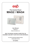
MAG2 MAG4 Version 4 English FIRE CONTROL PANEL User Manual /metal and plastic box/ Contents Guarantee...................................................................................................... 3 1. Using the MAG2/4 controls...................................................................... 4 1.1 Operation modes............................................................................... 5 1.2 LED indication for zones status....................................................... 5 1.3 LED indication for the technical troubles....................................... 5 1.4 LED indication for the system status.............................................. 6 1.5 Buttons for programming and operation........................................ 6 1.6 Switch for changing over between Access Levels 1 and 3........... 6 1.7 Sound signalization.......................................................................... 7 2. Installing the MAG2/4 fire panels............................................................ 7 3. Testing the MAG2/4 fire panels............................................................... 8 4. Connecting the zone circuits.................................................................. 8 5. Connecting the sounders circuits.......................................................... 9 6. Connecting the FAULT and FIRE relays................................................. 9 7. Class Change Function............................................................................ 9 8. Operation instructions........................................................................... 10 8.1 Zone Enabling/ Disabling .............................................................. 10 8.2 Sounders Enabling/ Disabling....................................................... 10 8.3 “One man” zone testing................................................................. 11 9. Technical specifications........................................................................ 12 10. Connection diagrams........................................................................... 13 11. Fire alarm record.................................................................................. 14 12. Service record...................................................................................... 14 13. Fire alarm event LOG........................................................................... 15 14. Spare parts kits.................................................................................... 15 WARNING The system is to be installed by a qualified person to the latest Fire Alarm and Installation Regulations which are mandatory in the applicable country of installation. Before commencing the installation of this Fire Alarm Panel, ensure it is sited in a position, which is visible to the Fire Brigade when entering the premises, and where ease of access is provided for users and service engineers. Space must be available to easily open external and internal doors. The Electrical Supply to the panel must be isolated and must not be capable of being accidentally switched off. A ‘Lockable Switch fuse Unit’ positioned within 2 meters of the panel should be clearly labelled FIRE ALARM - DO NOT SWITCH OFF. EN 54-2 compatible panels. All specifications are subject to change without notice. Technical Support help: +359 (2) 9694 800 2 Fire Control Panel MAG2/4 - User Manual GUARANTEE The guarantee terms are determined by the serial number (barcode) of the electronic device! During the guarantee period the manufacturer shall, at its sole discretion, replace or repair any defective product when it is returned to the factory. All parts replaced and/or repaired shall be covered for the remainder of the original guarantee, or 6 months, whichever period is longer. The original purchaser shall immediately send manufacturer a written notice of the defective parts or workmanship. International Guarantee Foreign customers shall possess the same guarantee rights as those any customer in Bulgaria, except that manufacturer shall not be liable for any related customs duties, taxes or VAT, which may be payable. Guarantee Procedure The guarantee will be granted when the appliance in question is returned. The guarantee period and the period for repair are determined in advance. The manufacturer shall not accept any product, of which no prior notice has been received via the RAN form at: http://www.teletek-electronics.com/en/support/Service The setup and programming included in the technical documentation shall not be regarded as defects. Teletek Electronics bears no responsibility for the loss of programming information in the device being serviced. Conditions for waiving the guarantee This guarantee shall apply to defects in products resulting only from improper materials or workmanship, related to its normal use. It shall not cover: • Devices with destroyed serial number (barcode); • Damages resulting from improper transportation and handling; • Damages caused by natural calamities, such as fire, floods, storms, earthquakes or lightning; • Damages caused by incorrect voltage, accidental breakage or water; beyond the control of the manufacturer; • Damages caused by unauthorized system incorporation, changes, modifications or surrounding objects: • Damages caused by peripheral appliances (unless such peripheral appliances have been supplied by the manufacturer: • Defects caused by inappropriate surrounding of installed products; • Damages caused by failure to use the product for its normal purpose; Damages caused by improper maintenance; • Damages resulting from any other cause, bad maintenance or product misuse. In the case of a reasonable number of unsuccessful attempts to repair the product, covered by this guarantee, the manufacturer’s liability shall be limited to the replacement of the product as sole compensation for breach of the guarantee. Under no circumstances shall the manufacturer be liable for any special, accidental or consequential damages, on the grounds of breach of guarantee, breach of agreement, negligence, or any other legal notion. Waiver This Guarantee shall contain the entire guarantee and shall be prevailing over any and all other guarantees, explicit or implicit (including any implicit guarantees on behalf of the dealer, or adaptability to specific purposes), and over any other responsibilities or liabilities on behalf of the manufacturer. The manufacturer does neither agree, nor empower, any person, acting on his own behalf, to modify, service or alter this Guarantee, nor to replace it with another guarantee, or another liability with regard to this product. Unwarranted Services The manufacturer shall repair or replace unwarranted products, which have been returned to its factory, at its sole discretion under the conditions below. The manufacturer shall accept no products for which no prior notice has been received via the RAN form at: http://www.teletek-electronics.com/en/support/Service The products, which the manufacturer deems repairable, will be repaired and returned. The manufacturer has prepared a price list and those products, which can be repaired, shall be paid for by the Customer. The devices with unwarranted services carry 6 month guarantee for the replaced parts. The closest equivalent product, available at the time, shall replace the products, the manufacturer deems unrepairable. The current market price shall be charged for every replaced product. ! This manual contains information on limitations regarding product use and function and information on the limitations as to liability of the manufacturer. The entire manual should be carefully read! Fire Control Panel MAG2/4 - User Manual 3 1. Using the MAG2/4 control Front view MAG2 Front view MAG4 Description of the front panels elements: LED indication for the zones status: MAG2 - 2 zones MAG4 - 4 zones Buttons for programming and operation, see item 1.5. LED indication for the system status, see item 1.4. LED indication for the technical troubles - see item 1.3. Note: This indication is not visible for the user. To examine the technical troubles in the system, the engineer has to remove the front cover of the box. Switch for changing over between Access Levels 1 and 2 - see item 1.6. 4 Fire Control Panel MAG2/4 - User Manual 1.1 Operation modes: MODE Normal Indication • The green LED next to the ‘power Supply 230V AC’ will be illuminated. Fire • The integrated red status FIRE LED and a zone identification LED will flash together on receipt of a FIRE condition and become steady after the SILENCE ALARM button is pressed. • An internal buzzer will operate until silenced with SILENCE BUZZER button. • The external sounders will operate. • The FIRE relay on the main board will energize. Fault • The yellow GENERAL FAULT LED will always illuminate together with an external or internal identification LED. • An internal buzzer will sound. • The FAULT relay on the main will de-energize. 1.2 LED indication for the zones status: ZONE LED Indication Red • Fire alarm in the zone. Yellow • Zone fault - open or short circuit. Detector head removed. • Zone test - the LED is blinking during the test procedure. 1.3 LED indication for the technical faults: FAULT ○ µP Fault description Processor break down. ○ Sounder 1 Sounder Circuit One fault - open or short circuit, reverse connected sounder, or bad sounder parameters. ○ Sounder 2 Sounder Circuit Two fault - open or short circuit, reverse connected sounder, or bad sounder parameters. ○ +24V DC Overload Overload of “+24” VDC power supply. ○ +24V DC Failed Absence of “+24” VDC power supply. ○ Battery Low Low battery condition. ○ Battery Lost Battery loss. ○ AC Mains Supply loss. ○ Charger Battery charger fault. ○ AUX Auxiliary supply fault. ○ Earth Short circuit to earth. Fire Control Panel MAG2/4 - User Manual 5 1.4 LED indication for the system status: LED Indication FIRE (red) Fire in the premises. GENERAL FAULT* (yellow) Main Fault indicator. SOUNDER FAULT/DISABLE* (yellow) Trouble in the sounder circuit - open or short circuit; reverse connected sounder. ENABLE / DISABLE (yellow) Lights permanently at disabled zones/sounders. Blinks during enabling/disabling of zones or sounders. TEST (yellow) Blinks during “One Man” Test together with the LED of the tested zone. POWER SUPPLY 230V (green) Lights on permanently in normal operating mode, indicates presence of main power supply 230V. 1.5 Buttons for programming and operation: Button Description SILENCE BUZZER Deactivating the internal buzzer. SILENCE ALARM Deactivating sounders. ENABLE / DISABLE Enabling / Disabling of Zones / Sounders. TEST / SCROLL Test mode; Scroll forward zones. RESET Initialization; Confirm the introduced changes. SOUND ALARM Activating sounders. 1.6 Switch for changing over between Access Levels 1 and 2: Position Description OFF Access Level 1 - only the “SILENCE BUZZER” button is active. ON Access Level 2 - all buttons at the front panel are active. * NOTE: Fault conditions will not be announced instantly. There will be a short delay which will vary from condition to condition. Faults when cleared will automatically reset at the panel. 6 Fire Control Panel MAG2/4 - User Manual 1.7 Sound signalization Signal Description Short beeps After pressing the “RESET” button and upon the initial start-up of the panel. Continuous beep Fire and/ or Fault operating mode. The signal can be stopped by pressing the “SILENCE BUZZER” button, but the LED indication remains. Interrupted beep After pressing the “ENABLE/DISABLE” button to enable/disable zones/ sounders and the “TEST/SCROLL” button to access “One Man” test mode of zones. The signal can be stopped by pressing the “SILENCE BUZZER” button, but the LED indication remains. 2. Installing the MAG2/4 fire panels • Choose the best location for the panel position, with an ambient temperature between -5°C and 40°C, away from heating sources, environmental dust and potential water ingress. • Remove all packaging and inspect visually the panel for any damage. • Remove the outer cover, by unscrewing the screws on the front cover. Stow the cover in a safe position. • Inspect the internal PCB and make sure the internal components are firmly in place. • Remove the PCB from the metal / plastic box. Stow in a safe location. • Choose which cable entry points to knock out and carefully remove the knock-outs. • Drill the wall to suit the back box centre fixing position, plug and insert a fixing screw. Note: If you are installing MAG 2/4 in plastic box use the template on the back side of the packaging box to drill the mounting holes on the wall. • Fix the metal / plastic housing into mounting position and insert fixing screws. • Tighten all the fixing screws. • Route the external cables onto the back box, make off connection glands etc., DO NOT make any connections at this stage. ENTER THE MAINS CABLE THROUGH ITS OWN CABLE ENTRY POINT AND KEEP MAINS WIRING AWAY FROM SYSTEM AND OTHER LOW VOLTAGE WIRING. • Fit the EOL modules from the supplied additional parts one-by-one to every zone terminal. Attention: Observe the polarity - the red wire to “+” point and the black wire to “-” point. • Fit the EOL resistors from the supplied additional parts one-by-one to the sounders terminal. • Re-fit the PCB to the metal / plastic box. • Connect the mains supply and earth to the main terminal block. DO NOT switch on the main electrical supply at this stage. • Position the battery in an upright position. Fire Control Panel MAG2/4 - User Manual 7 3. Testing the MAG2/4 fire panels ! ATTENTION: It has been assumed that prior to making the connection at the panel, the integrity of the system ALL wiring has been comprehensively tested, including insulation to earth. • Connect the battery leads from the black power supply box to the positive and negative battery terminals. • Switch on the mains power supply. • If the buzzer and indicator LED’s are operating, press the RESET button. In Normal Operating Mode only POWER SUPPLY 230V will be illuminated. NOTE: The battery might show a ‘Low Battery Fault’ initially until it has had time to charge up to the required level. If other LED’s are illuminated and the buzzer is sounding, carefully check all fuses and connections. Refer to the page 7 for the associated yellow LED’s apply to. The connection diagram on the inside of the external cover will assist in identifying the LED. ! ATTENTION: Do not short out the battery terminals because an internal protection will switch on and the panel will stop function! If by some chance the fault will not cancel, and only on the advice of our Technical Support Department, return the PCB CHASSIS ONLY to your supplier. DO NOT return the metal / plastic box. 4. Connecting the zones circuits • Disconnect the mains power supply and the battery connection. • Remove the EOL-module from the zone 1 terminal on the main module and fit it to the last detector of the zone 1 circuit as observe the polarity: • Ensure all terminations are made correctly and all detector heads are plugged into their bases. • Connect Detector circuit one to the panel terminal block. • Power up the panel with the mains and battery. • Press RESET button. The panel should be in the ‘NORMAL MODE’. 8 If General Fault and zone 1 FAULT LED’s illuminate, there is a wiring/ connection problem. Check the polarity of the connection, the connection of the devices and whether a head is removed. Check the EOL proper polarity and position. Fire Control Panel MAG2/4 - User Manual • Operate ALL detection devices applicable to this zone, to ensure correct receipt of a fire signal and the correct operation of the panel controls. Refer to the User Instructions on the inside of the panel. • Repeat the connection process for the other zones stated above. ENSURE the supply voltages are initially disconnected prior to each stage. ! Once the connection of the zones is completed, connect and test any of the other auxiliary circuits before connecting the external sounder circuits. 5. Connecting the sounders circuits Sounders • Disconnect the mains power supply and the battery connection. • Remove the EOL-Resistor from the terminal block of sounder circuit 1 (SND 1) and fit to the last sounder of circuit one: S1 S2 SN 10K LEGEND black red brown • Check all sounder connections are made. • Connect sounder circuit ONE to the panel terminal block. • Apply mains and battery power. • Press RESET. The panel should be in the ‘NORMAL MODE’. • Activate a zone Call Point. The sounders should operate. Press the reset button. Repeat the connection process for the second external sounder circuit, as stated above. ENSURE the supply voltages are initially disconnected prior to each stage. If General Fault and SOUNDER FAULT / DISABLE LED’s illuminate, there is a wiring / connection problem. Check the polarity of the connection of each of the devices, the polarity of the connection of the devices to the Panel terminal block or whether an earth fault exists. 6. Connecting the FAULT and FIRE relay circuits FAULT and FIRE Relays - The on board relays volt free change over terminals are for low voltage use only. Attention: Mains supply MUST NOT BE APPLIED to these terminals. 7. Class Change Function To use the class change function connect the terminals of a switch with normally open contacts to the CC (Class Change) clamps of the main module terminal. The working mode of the sounders will be: - when the switch is pressed - one second sounder on, one second sounder off; - when the switch is depressed - the sounder is off. Fire Control Panel MAG2/4 - User Manual 9 8. Operation instructions 8.1 Zone Enabling/ Disabling Z To disable a zone: • Press ENABLE/ DISABLE: DISABLE/ ENABLE LED blinks. The ZONE 1 yellow LED blinks if ZONE 1 is enabled and lights permanently if ZONE 1 is disabled. • Press TEST/ SCROLL, until you reach the zone which has to The respective zone yellow LED blinks. be disabled: • Press ENABLE/ DISABLE: The yellow LED of the disabled zone lights up permanently. • Press RESET: At this step the zone is disabled. Z To enable a zone: • Press ENABLE/ DISABLE: DISABLE/ ENABLE LED blinks. The ZONE 1 yellow LED blinks if ZONE 1 is enabled and lights permanently if ZONE 1 is disabled. • Press TEST/SCROLL, until you The yellow LED of the disabled zone lights up perreach the zone which has to enmanently. able: • Press ENABLE/ DISABLE: The yellow LED of the enabled zone blinks. • Press RESET: At this step the zone is enabled. 8.2 Sounders Enabling/ Disabling ! A sound signalization is activated at every Service Mode entering. The signalization is off by pressing “SILENCE BUZZER” button. Z To disable the sounders: • Press ENABLE/ DISABLE: DISABLE/ ENABLE LED blinks. The ZONE 1 yellow LED blinks if ZONE 1 is enabled and lights permanently if ZONE 1 is disabled. • Press TEST/ SCROLL, until The SOUNDER FAULT/DISABLE LED will start you reach the last zone in the blinking. system: • Press ENABLE/ DISABLE: 10 The SOUNDER FAULT/DISABLE LED lights up permanently. Fire Control Panel MAG2/4 - User Manual • Press RESET: The SOUNDER FAULT/DISABLE and ENABLE/ DISABLE LEDs light up permanently. At this step the sounders are disabled. You can exit the sounder disabling mode also by pressing the “TEST/ SCROLL” button, as in that case the you reject the procedure. Z To enable the sounders: • Press ENABLE/ DISABLE: DISABLE/ ENABLE LED blinks. The ZONE 1 yellow LED blinks if ZONE 1 is enabled and lights permanently if ZONE 1 is disabled. • Press TEST/ SCROLL, until The SOUNDER FAULT/DISABLE LED lights up you reach the last zone in the permanently. system: • Press ENABLE/ DISABLE: The SOUNDER FAULT/DISABLE LED will start blinking. • Press RESET: At this step the sounders are enabled. You can exit the sounder enabling mode also by pressing the “TEST/ SCROLL” button, as in that case the you reject the procedure. 8.2 “One man” Zone Testing The “One Man” Test mode gives the installer the possibility to test the efficiency of the system - whether the detectors react to smoke, heat, etc. Z To do “One Man” Test of a zone: • Press TEST/ SCROLL: TEST LED will start blinking. µP Fault LED lights off. All other system indication LEDs light on permanently. • Press TEST/ SCROLL again: The ZONE 1 yellow LED starts blinking. ZONE 1 is in test mode. Test a detector from this zone whether it react to smoke, heat, etc. TEST LED will continue blinking. The ZONE 1 yellow LED lights out (the zone is • Press TEST/ SCROLL again to not longer in test mode). The ZONE 2 yellow LED continue with the system testing: blinks in yellow. ZONE 2 is in test mode. Test a detector from this zone whether it react to smoke, heat, etc. Continue the system testing by pressing the “TEST/ SCROLL” button. The exit from the “One Man” Test mode is automatic after the end of the test procedure in the last Zone 4, or at any time by pressing “RESET” button. Fire Control Panel MAG2/4 - User Manual 11 9. Technical Specifications of MAG2 and MAG4 Zones: • MAG 2 - 2 fixed zones • MAG 4 - 4 fixed zones Maximum number of detectors per zone: • Up to 20 (or 32 SensoMAG series) conventional detectors and unlimited number of manual call points. Thresholds for zone conditions: • 0 ÷ 2 mA - Open circuit fault condition • 2 ÷ 6 mA - Normal condition • 6 ÷ 110 mA - Fire Alarm condition • 110 mA - Short circuit condition Power Supply: • Main Power supply: 230V AC ±10%; 0.315A fuse • Standby Power supply: 1 x 12V / 7Ah; 2A fuse Maximum current available for system devices (with fully charged battery): • 0.7 A Current consumption - mains failure: • 50 mA Outputs: • Sounder Circuit 1: 24V / 0.3A; 0.3A fuse (PTC) • Sounder Circuit 2: 24V / 0.3A; 0.3A fuse (PTC) • Fault Relay, volt free changeover contacts*: 3A @ 120V AC; 3A @ 60V DC • Fire Relay, volt free changeover contacts*: 3A @ 120V AC; 3A @ 60V DC * Note: These functions may not be used to provide any “Options with requirements” as specified in EN 54-2. Auxiliary output: • 24V DC, 0.3A fuse (PTC) Cabling: • Maximum 2.5mm diameter Environment: • Working temperature: -5 to 40°C • Storage temperature: -20 to 60°C • Humidity: 0 to 95% 12 Fire Control Panel MAG2/4 - User Manual 10. Connection Diagrams Connection circuit MAG2/4 metal box Connection circuit MAG2/4 plastic box Fire Control Panel MAG2/4 - User Manual 13 11. Fire Alarm Record Installation Address: Contact Person: ........................................................................................................ ........................................................................................................ ........................................................................................................ ........................................................................................................ ........................................................................................................ ........................................................................................................ Telephone: ........................................................................................................ Fax: ........................................................................................................ Date Completed: ........................................................................................................ Commissioned By: ........................................................................................................ Contract Reference: ........................................................................................................ Service Intervals: ZONE No Monthly / Quarterly / Half Yearly / Annually LOCATION SOUNDERS (Zone Quantity and Related Circuit ) DETECTOR TYPE and QUANTITY PER ZONE Ion* Ph RoR F/T CP Circuit1 Circuit2 1 2 3 4 TOTALS: * Ion - Ionisation sensor, Ph - Photoelectric sensor, RoR - Rate of Rise sensor, F/T - Fixed Temperature sensor, CP - Call Point System Installed By:.......................................................................................................... Telephone / Fax:. ............................................................................................................... 12. Service Record Date Visit Completed 14 Zones Tested Faults Rectified Signature of Engineer 1234 Name: 1234 Name: 1234 Name: 1234 Name: Next Due Fire Control Panel MAG2/4 - User Manual 13. Fire Alarm Event LOG DATE TIME FIRE yes / no ZONE number FAULT yes/no and TYPE ACTION TAKEN Name 14. Spare Parts Kits Fire Control Panel MAG2/4 - User Manual 15 Address: 14A Srebarna Str., 1407 Sofia, Bulgaria tel.: (+359 2) 9694 800, fax: (+359 2) 962 52 13 e-mail: [email protected] 18020526, Rev.D, 01/2012 www.teletek-electronics.com