1
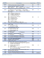
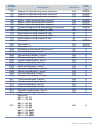
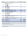
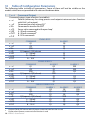
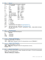
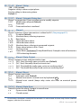
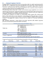
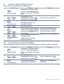
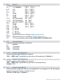
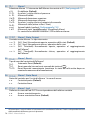
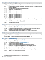
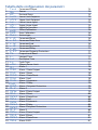
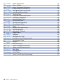
Tabella delle configurazioni dei parametri
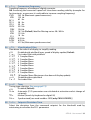
1 C.out Command Output
2 SEN.Sensor
3 d.P.
Decimal Point
4 Lo.L.S. Lower Limit Setpoint
5 up.L.S. Upper Limit Setpoint
6 LoL.i
Lower Linear Input
7 up.L.i. Upper Linear Input
8 Latc. Latch On Function
9 o.cAL. Offset Calibration
10 G.cAL. Gain Calibration
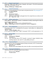
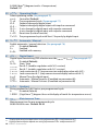
11 Act.t. Action type
12 c. re. Command Reset
13 c. S.e. Command State Error
14 c. Ld. Command Led
15 c. HY. Command Hysteresis
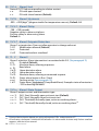
16 c. de. Command Delay
17 c. s.p. Command Setpoint Protection
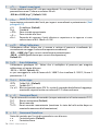
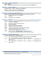
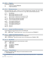
18 p.b.
Proportional Band
19 t.i.
Integral Time
20 t.d.
Derivative Time
21 t.c.
Cycle Time
22 o.PoL. Output Power Limit
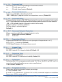
23 AL.1
Alarm 1
24 A.I.5.0 Alarm 1 State Output
25 a1.re. Alarm 1 Reset
26 a.1.s.e. Alarm 1 State Reset
27 a.1.Ld. Alarm 1 Led
28 a.1.Hy. Alarm 1 Hysteresis
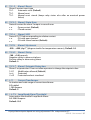
29 a.1.de.
Alarm 1 Delay
30 a.1.sp. Alarm 1 Setpoint Protection
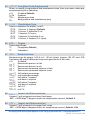
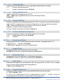
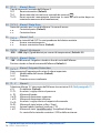
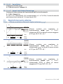
31 AL. 2
Alarm 2
32 a.2.so. Alarm 2 State Output
33 A2.re. Alarm 2 Reset
34 a.2.s.e. Alarm 2 State Error
35 a.2.Ld. Alarm 2 Led
36 a.2.HY. Alarm 2 Hysteresis
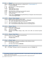
37 a.2.d.e. Alarm 2 Delay
38 a.2.s.p. Alarm 2 Setpoint Protection
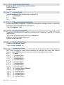
39 AL. 3
Alarm 3
40 a.3.5.o. Alarm 3 State Output
41 a.3.re. Alarm 3 Reset
42 a.3.s.e. Alarm 3 State Error
43 a.3.Ld. Alarm 3 LED
74
75
75
75
75
75
75
76
76
76
76
76
76
76
77
77
77
77
77
77
77
77
78
78
78
78
78
79
79
79
79
79
80
80
80
80
80
80
80
81
81
81
81
Manuale d’uso CN243 - 89