1
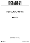
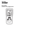
DIGITAL MULTIMETER
OPERATION MANUAL
1. SUMMARIZE
The instrument is a steady performance, battery-driven digital multimeter.It uses the LCD with 30mm-high figure to make the reading
clear. The function of 15 sec. backlight displaying and overload
protection make operation more convenient.
The instrument has the function of measuring DCV, ACV, DCA,
ACA, resistance, capacitance, test,temperature and frequency,
anddiode,triode and continuity test. The instrument takes
dual-integral A/D converter as key point, is an excellent tool.
2. SAFETY NOTE
This series meter's design meets the article of IEC1010 (security stan
dard enacted by IEC). Please read the following before operation.
1 Do not input a limited voltage higher than DC 1000V or AC
750Vwhen measuring ranges.
2 Voltage less than 36V is a safety voltage. When measuring
voltage higher than DC 36V, AC 25V, check the connection and
insulation of test leads to avoid electric shock.
3 Be sure to keep the test leads off the testing points when con
verting function and range.
4 Select correct function and range to avoid fault operation.
5 When measuring current, do not input current over 20A.
6 Safety symbols
exists high voltage
GND
dual
insulation
must refer to manual
low battery
3. CHARACTERISTIC
1 GENERAL
1-1 Displaying: LCD displaying,
1-2 Max. indication: 1999 3 1/2 , auto polarity indication,
1-3 Measuring method: dual slope A/D transfer,
1-4 Sampling rate: approx. 3 times/sec
1-5 Over range indication: MSD displays 1 or -1 ,
1-6 Low battery indication:
symbol displays,
1-7 Operation: (0 40)
relative humidity <80%,
1-8 Power one 9V battery (NEDA1604/6F22 or equivalent
1-9 Size: 189 97 35 mm (length width height)
1-10 Weight: approx.375g (including a battery)
1-11 Accessories: test leads, user manual, holster, gift box, and
9v battery.
1-12. testing accessories: a pair of alligator clip, a test accessory for
Triode,banana-type hot thermocouple..
2 TECHNICAL CHARACTERISTIC
2-1 Accuracy: (a% rdg d) at (23 5)
R.H.<75% one
year guaranteed from the production date.
2-2 TECHNICAL DATA
2-2-1.DC VOLT (DCV)
Range
Resolution
Accuracy
200mV
2V
100uV
(0.5%+3)
20V
1mV
10mV
200V
100mV
(1.0%+5)
1000V
1V
Input resistance: 10M .
Overload protection: 200mV range: 250V DC or AC peak value.
Other range: 1000V DC or AC peak value.
2-2-2. AC VOLT (ACV)
Range
Resolution
Accuracy
2V
20V
1mV
(0.8%+5)
10mV
200V
100mV
(1.2%+5)
750V
1V
Input resistance: 10M .
Overload protection: 1000V DC or AC peak value.
Frequency response: less than 200Vrange: 40 400 Hz
750V range: 40 200 Hz.
Displaying: sine wave rms(mean value response).
2-2-3.DC CURRENT(DCA)
Range
Resolution
Accuracy
20uA
200uA
0.01uA
(0.8%+4)
20mA
0.1uA
10uA
200mA
(1.2%+4)
2A
(1.5%+5)
100uA
1mA
(2.0%+5)
20A
10mA
Max. input volt drop: 200mV
Max. input current: 20A the test time should be in 10 seconds
Overload protection: 2A/250V quick-action fuse, 20A un-fused
1
2-2-4. AC CURRENT(ACA)
Accuracy
Resolution
200mA
(2.0%+5)
100uA
2A
(3.0%+5)
1mA
Range
(3.0%+10)
10mA
20A
Max. measuring volt drop: 200mV
Max. input current: 20A the test time should be in 10 seconds
Overload protection: 2A/250V quick-action fuse, 20A un-fused
Frequency response: (40 200)Hz
Display: sine wave RMS (mean value response)
2-2-5. RESISTANCE( )
Resolution
Accuracy
Range
200
(0.8%+5)
0.1
1
2k
20k
10
(0.8%+3)
100
200k
1k
[5.0%(RDG-10)+20]
100 k
200M
Open voltage: less than 3V
Overload protection: 250V DC and AC peak value
NOTE:
A.at 200 range, should make the test leads short, and
measure the wire resistance, then, subtract from the actual
measuring.
B.at 200M range, should make the test leads short, the meter
will display 1.0 M . It's normal and has no effect on the
accuracy. Should be subtracted from actual measuring.
2-2-6. CAPACITANCE(C)
2M
Range
Resolution
Accuracy
10pF
20nF
2uF
1nF
(2.5%+20)
100nF
200uF
Overload protection: 36V DC or AC peak value.
2-2-7. DIODE AND CONTINUITY TEST
Range
Displaying
Test condition
The positive DC current is
Positive voltage drop of
approx. 1mA negative
voltage is approx. 3V
diode
Buzzer sounds , the resistaopen voltage is approx. 3V
nce is less than (70 20)
Overload protection: 250V DC or AC peak value
Warning: DO NOT input any voltage at this range for safety!
2-2-8. TRANSISTOR hFE DATA TEST
Range
Displaying
Test condition
hFE NPN or PNP
0 ~ 1000
2-2-9.HOT WIRE TEST
Range Displaying Alarming Way
Basic current is approx.
10uA Vce is about 3V
condition
TEST
000or1
sound, light
Standard AC hot wire test
Overload protection DC 500V or AC peak value
CAUTION BE CAREFUL WHEN
YOU OPERATE IT.
4. OPERATION
4-1 Panel description (SEE
THE FIG).
1 LCD: display the measuring value
2-1 POWER switch: turn on/off
the power.
2-2 B/L switch: turn on/off the
back light.
AUTO
POWER
OFF
2-3 HOLD key: press it, the max. of presently measured value is
held on LCD and HOLD symbol displays. Press it again,
HOLD symbol disappears, and the meter is exited the
holding mode.
2-4.The light of hot wire testing,
3 Range knob: to select measuring function and range.
4 Voltage, resistance and frequency COM
5 GND, the anode COM of test accessory,
6 2A current test COM, the cathode COM of test accessory,
7 COM for measuring current 20A
4-2 DCV measurement
1. Apply the black test lead to COM terminal and the red one to
V/
terminal.
2. Set the knob to a proper DCV range , and connect the leads
crossly to the electric circuit under test, LCD displays polarity
and voltage under test connected by the red test lead.
Note
1. Firstly users should set the knob to the highest range, if users
had no idea about the range of voltage under test, and then
select the proper range based on displaying value.
2. If LCD displays 1 , it means meter is over the max. Value
of range, thus should set the knob to a higher range.
3. Do not input a voltage over DC 1000V.
4. Be carefully while measuring a high voltage. DO NOT touch
the circuit.
4-3. ACV measurement
1. Apply the black test lead to COM terminal and the red one
to V/
terminal.
2 Set the knob to a proper ACV range, and then connect the leads
crossly to the electric circuit under test.
NOTE:
1. Firstly users should set the knob to the highest range, if
users had no idea about the range of voltage under test, and
then select the proper range based on displaying value.
2. If LCD displays 1 , it means meter is over the max.
value of range, thus should set the knob to a higher range.
3. Do not input a voltage over 750Vrms.
4.Be carefully while measuring a high voltage. DO NOT touch
the circuit.
4-4. DCA Measurement
1. Apply the black test lead to COM terminal and the red one to
mA terminal (the Max. 2A) or to 20A (the Max.20A);
2. Set the knob to a proper DCA range, and connect the leads
crossly to the electric circuit under test; LCD displays polarity
and current under test connected by the red test lead.
NOTE:
1 Firstly users should set the knob to the highest range, if
users had no idea about the range of current under test, and
then select the proper range based on displaying value.
2 If the LCD displays 1
it means the current is over
range.Now you need to set the knob to the higher.
3 Max. input current is 2Aor 20A(subject to where the red
test lead apply to), too large current will blow the fuse. Too
large continuous current will heat the circuit, affect
theaccuracy or damage the meter while measuring at the
range of 20A, because there is no protection.
4-5. ACA Measurement
1. Apply the black test lead to COM terminal and the red one to
mA terminal (the Max. 2A) or to 20A (the Max.20A);
2. Set the knob to a proper ACA range, and connect the leads
crossly to the electric circuit under test.
2
NOTE:
1 Firstly users should set the knob to the highest range, if
users had no idea about the range of current under test, and
then select the proper range based on displaying value.
2 If the LCD displays 1
it means the current is over
range. Now you need to set the knob to the higher.
3 Max. input current is 2Aor 20A subject to where the red
test lead apply to , too large current will blow the fuse.
Be sure the test is less than 10 seconds. Please keep the
leads off the circuit while switching the function and range
knob.Too large continuous current will heat the circuit,
affect the accuracy or damage the meter while measuring
at the range of 20A, because there is no protection.
4-6. Resistance Measurement
1. Apply the black lest lead to COM terminal and the red one to
V/
terminal.
2. Set the knob to a proper resistance range, and connect the leads
crossly with the resistor under tested.
NOTE
1. The LCD displays 1 while the resistance is over the
selected range. The knob should be adjusted to a higher
range. When measuring value is over 1M , the reading
will take a few seconds to be stable. It's normal for high
resistance measuring.
2. When input terminal is in open circuit, overload displays.
3. When measuring in line resistor, be sure that the power is
off and all capacitors are released completely.
4. Do not input any voltage at resistance range.
4-7. Capacitance Measurement
1. Apply the knob to proper capacitance range, and insert the
measuring accessories or test leads into COM and mA
terminal. Note: COM terminal is for positive pole ,
mA terminal is
.
2. Connect test leads with the two points of capacitor, be wary of
polarity if necessary.
NOTE:
1. If the capacitance under tested is over the max. value of
selected range, LCD displays 1 , thus, should set the
knob to a higher range.
2. It's normal that there is a remained value on LCD before
capacitance measurement, and it doesn't affect the
measurement.
3. When measuring at large capacitance range, if capacitor is
crept badly or broken, LCD displays a value and it's unstable.
4. Release the capacitor completely before measuring.
4-8. TRANSISTOR hFE
1. Set the knob to hFE range. Inset the test leads to COM and
mA . Note: COM terminal is for positive pole , mA
terminal is
.
2. Verify the transistor under tested is NPN or PNP, insert emitter,
base and collector to proper jack.
4-9. Diode and Continuity Test
1. Apply the black test lead to COM terminal and the red one to
V/
terminal (the polarity of red lead is + ).
2. Set the knob to
range, connect test leads with the diode
under tested, the red test connect to diode positive polarity, the
reading is the approx. value of diode forward volt drop.
3. Apply test leads to two points of tested circuit, if the inner buzzer
sounds, the resistance is less than (70 20) .
4-10. Hot Wire Test
1. Pull out the black test lead from COM jack, and set the red
one to V/
jack,
2. Set the knob to TEST range, and set the red test lead to the
tested circuit,
3. If LCD displays 1 and the light and sound alarming, it means
the circuit of the red test lead tested is hot wire; if there is no any
response, it means it is neutral wire.
NOTE:
1 The function is only for testing AC standard live wire
( AC 110V~AC 380V)
2 Be careful to operate at this range.
4-11. Data Hold
Press the Hold switch, the measured value is held on LCD, press it
again and the function is cancelled.
4-12 AUTO POWER OFF
The meter will be into sleeping mode when it works for 20 10
minutes. Press POWER key twice to restart the power.
4-13. BACKLIGHT
Press B/L key to turn on the backlight, and it will turn off after
15 secretary
NOTE:
When turning on backlight, the working current will be
enlarged, it leads to shorten battery usage and enlarge
accuracy of some functions.
5 Maintenance
Do not try to modify the electric circuit.
5-1. Keep the meter away from water, dust and shock.
5-2. Do not store and operate the meter under the condition of high
temperature, high humidity, combustible, explosive and strong
magnetic place.
5-3. Wipe the case with a damp cloth and detergent, do not use
abrasives and alcohol.
5-4. If do not operate for a long time, should take out the battery to
avoid leakage.
5-4-1. When
signal displays, should replace the battery
following the steps
5-4-1-1. Unlock the button and remove the battery case.
5-4-1-2. Take out the old battery and replace the new one. It's
better to use alkaline battery for longer life.
5-4-1-3. Fit on the battery case and lock the button.
5-4-2. fuse change: When replacing fuse, please change another
same type and specification fuse.
6. If the meter does not work properly, check the meter as following:
Conditions
Way to solve
Turn on the power
No reading on LCD
Set the HOLD key to a correct mode
Replace battery
signal appears
Replace battery
No current or temperature input
Replace fuse
Big error Value
Replace battery
The specifications are subject to change without notice.
The content of this manual is regarded as correct, error or
omits Pls. contact with factory.
We hereby will not be responsible for the accident and
damage caused by improper operation.
The function stated for this User Manual cannot be the
Reason of special usage.
MB-0088-11
3