1
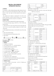
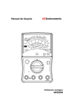
DIGITAL MULTIMETER 20V 1mV 200V 10mV b. In 200MΩ range, should make the test leads short, LDC will display 10.00MΩ, which is normal situation, subtracts it from the real measurement. 100mV 3-2-6.CAPACITANCE 1000V OPERATION MANUAL 1. GENERAL This digital multimeter is a steady performance, battery-driven 4 1/2 digital multimeter. It uses the LCD with 28mm high figure to make the reading clear and make operation more convenient. The digital multimeter has the function of measuring DCV, ACV, DCA, ACA, resistance, capacitance, transistor and diode, and continuity performance test, etc. The meter can provide functions including unit symbol display, data holding, It adopts double integral A/D converter as its core. It is an ideal tool for labs, factories and radio-technology. 2. SAFETY The instrument is designed according to IEC1010 standard (safety standard issued by International Electro technical Committee). Please read the safety note before operation. 2-1. Do not input a limited voltage higher than DC 1000V or AC 750V when measuring ranges. 2-2. The voltage below 36V is safety. To avoid electric shock, check whether the test leads are connected correctly, whether the insulation is good when measuring over 36DCV or 25ACV. 2-3. The test leads should be removed from the testing point when changing function and range. 2-4. Choose correct function and range to avoid wrong operation. 2-5. Do not input current higher than 20A when measuring current. 2-6. Specification of safety signal “ ” existing dangerous volt “ ” GND “ ”dual insulation “ ” operator must refer to the manual “ ”low battery indication 3. SPECIFICATION 3-1.GENERAL 3-1-1. Displaying: LCD display 3-1-2. Max. displaying:19999(4 1/2)auto-polarity display 3-1-3. Measuring method:dual-slope A/D transfer 3-1-4. Sampling rate:approx. 3 times/sec 3-1-5. Over-range display: “1” or “-1”displayed in the highest digit. 3-1-6. Low battery display:“ ” displays 3-1-7. Operation :(0~40)℃,relative humidity <80% R.H 3-1-8. power: 9V battery (NEDA1604/6F22 or equivalent) 3-1-9. Dimension: 185mm×93mm×35 mm 3-1-10. Weight: approx. 290g (including battery) 3-1-11. Accessories: user manual, test leads, holster, gift box, and 1*9V battery. 3-2.TECHNICAL SPECIFICATION 3-2-1. Accuracy: ±(a% × reading+digits)at 23 ± 5℃,<75% R.H,one year guarantee from production time. 3-2-2.DCV Range 200mV 2V Accuracy ±(0.05%+3) Resolution 10uV 100uV ±(0.1%+5) Range Input impedance:10MΩ at all ranges Over-range protection:250 DCV or AC peak value at 200mV range, 1000 DCV or DC peak value at other range 3-2-2.AC Range Accuracy 2V ±(0.8%+25) 200V ±(1.0%+25) Accuracy 200uA 100mV Resolution 0.01uA ±(0.5%+4) 2mA 20mA ±(3.8%+20) 10nF Range Accuracy Resolutio 200kHz ±(3%+15) 10Hz Input sensitivity:1V RMS; Overload protection:250V DC or AC peak value (less than 10sec.). 3-2-8.DIODE AND CONTINUITY TEST RANGE ±(0.8%+6) 10uA ±(2.0%+15) 1mA Max. measuring volt drop: 200mV Max. input current: 20A(less than10 seconds) Overload protection: 0.2A / 250V fast blow fuse; 20A range without fuse. DISPLAYING VALUE Diode forward volt drop 1uA 20A TEST CONDITION Forward DC current is approx. 1mA , backward voltage is approx. 3V Buzzer rings, the impedance Open voltage is approx. between the two testing points 3V is less than(30±10)Ω Overload protection:250DCV or ACV peak value; Warning: do not input any voltage value at this range for safety! 3-2-9. hFE 3-2-4.ACA Range Accuracy 200mA ±(1.5%+25) 10uA 20A ±(2.5%+35) 1mA Resolution Max. measuring volt drop:200mV Max. input current:20A(less than 10 seconds) Overload protection: 0.2A / 250V with fuse,20A range without fuse. Frequency response:40~200Hz Displaying:sine wave RMS(mean value response) 3-2-5. RESISTANCE(Ω) Range Accuracy 200Ω ±(0.2%+10) 2kΩ Resolution 0.01Ω 0.1Ω ±(0.2%+5) 2MΩ 200MΩ 100pF 3-2-7.FREQUENCY 0.1uA 200mA 200kΩ 10pF 2uF 200uF 3-2-3.DCA Range 1pF ±(3.5%+10) Testing frequency: 400Hz; Overload protection:36 DCV or ACV peak value. Input impedance:10MΩ at all ranges Over-range protection:1000 DCV or DC peak value at other range Frequency response:below 200V:40~400Hz,750Vrange:40~200Hz Displaying:sine wave RMS(mean value response ) 20kΩ 20nF 1mV 10mV 750V 0.1pF 200nF Resolution 100uV 20V Resolutio Accuracy 2nF 1Ω 10Ω 100Ω ±[5%(reading-10.00)+10] 10kΩ Open circuit voltage:less than 3V; Overload protection:250DCV or ACV peak value; Note: a. In 200Ω range,should make the test leads short, and measure the resistance of the wire, then, subtracts from the actual measuring value. Range hFE NPN or PNP Scope 0~1000 Testing condition Base DC current is approx. 10uA,Vce is approx. 3V 4.OPERATION 4-1.Front panel ①. LCD: display the measured value; ②Function key; ②-1. Power switch: turn on or off the power ②-2. HOLD key: press the key down, the measured value will be hold and “HOLD” signal appears; press it down again,“ HOLD ”signal disappears and out of the HOLD mode. ②. Backlight; ③.hFE testing terminal:for measuring transistor hFE; ④.Knob switch: for changing function and range; ⑤.Terminal for capacitance; ⑥.Terminal for Voltage, resistance, frequency and GND testing; ⑦.Battery case; 4-2.DCV measurement 4-2-1. Apply the black test leads to “COM” terminal and the red one to V/Ω/Hz terminal. 4-2-2. Switch the knob to a proper DCV range, then, connect the test leads cross the measured circuit, the voltage and polarity of the point which connected with the red test lead will be displayed. NOTE: 1. If the voltage under measured is unclear beforehand, should set the range knob to the highest range, then, switch to a proper range according to the displaying value.. 2. The remained digits do not affect on measuring accuracy when we haven’t measure the low voltage. If LCD displays“1”, it means over-range, the range knob must be switched to a higher range. 2. Do not input a voltage over 1000V, or the meter might be damaged. 3. Be careful when measuring high voltage circuit. 4-3.ACV measurement 4-3-1. Apply the black test leads to “COM” terminal and the red one to V/Ω/Hz terminal. 4-3-2. Set the range knob to a proper ACV range, and then connect the test leads cross to the measured circuit. NOTE: 1. If the range under measured is unclear beforehand, should set the range knob to the highest range, then, switch to a proper range according to displaying value.. 2. The remained digits do not affect on measuring accuracy when we haven’t measure the low voltage. If LCD displays “1”, it means over-range, should set the range knob to a higher range. 3. Do not input a voltage over 750Vrms, or, the meter might be damaged. 4. Be careful when measuring high voltage circuit. 4-4. DC current measurement 4-4-1. Apply the black test leads to “COM” terminal and the red one to “mA” terminal (Max.200mA), or the red test lead to “20A”terminal (max. 20A) 4-4-2. Set the range knob to a proper DCA current range, then, connect the meter to the measured circuit, the measured current value and the current polarity which the red test lead connect will be displayed on LCD. NOTE: 1. If the range under measured is unknown beforehand, should set the range knob to the highest range, then, switch to a proper range according to the displaying value; 2. If LCD displays“1”,it means over-range, the range knob must be set to a higher range. 3. The max. input current is 200mA or 20A (subject to the position where the red test lead insert), large current may blow the fuse. Be careful especially at 20A range, because there is no fuse protection at this range, large current may heat the circuit, even damage the meter. 4-5.AC current measurement 4-5-1. Apply the black test lead to "COM” terminal,and the red one to "mA” terminal (max. 200mA), or the red test lead to “20A”terminal (max. 20A); 4-5-2. Set the range knob to a proper AC current range, then, connect the meter to the circuit under measured. NOTE: 1. If the current range under measure is unknown beforehand, should set the range knob to the highest range, then, switch to the proper range according to the displaying value. 2. If LCD displays“1”,it means over-range, must set the range knob to a higher range. 3. The max. input current is 200mA or 20A(subject to the position where the red test lead insert),large current might blow the fuse,be careful especially at 20A range, because there is no fuse protection at this range, large current may heat the circuit, even damage the meter. 4-6.Resistance measurement 4-6-1. Apply the black test lead to COM terminal,and the red one to V/Ω/Hz terminal. 4-6-2. Set the range knob to a proper resistance range, connect the test leads across the resistance under measured. NOTE: 1. If the resistance value is over the selected range value, "1" displays, thus, should set to a higher range. When measuring value is over 1MΩ,the reading needs a few seconds to be stable. It's normal for high resistance measuring. 2. When input terminal is open-circuit, overload displays. 3. Before measuring in-line resistance, be sure that power is off and all capacitance are released. 4. If big error appears, perhaps it was affected by other elements or there existed voltage on the resistance. 5. Do not input voltage at this range. 4-7.Capacitance measurement Set the knob to proper capacitance range, and insert the capacitor under tested. NOTE: 1. If "1" displays, it means over-range, should set to a higher range. 2. The remained digits do not affect on measuring accuracy before measuring; 3. If creeps seriously or the capacitor is breakdown when measuring large capacitance, some digits are displayed and unstable; 4. Please do not measure the capacitance on line; 5. Before measuring, should release the capacitor completely to avoid damage. 4-8.Frequency measurement 4-8-1.Apply the test leads or shield cable to “COM” and V/Ω/Hz terminal. 4-8-2.Switch the range knob to frequency range, connect the test leads across to the signal source or the measured load. NOTE: 1.When input is over 10Vrms,reading is possible but maybe over range. 2.It's better to use shielding cable on noisy condition when measuring small signal. 3.Be careful when measuring high volt circuit. 4.Do not input a voltage over 250DCV or AC peak value to avoid damage the meter. 4-9. Transistor hFE 4-9-1. Set the range to hFE range. 4-9-2. Select NPN or PNP , insert separately emitter, base and collector to proper terminal. 4-10.Diode and continuity test 4-10-1.Apply the black test lead to “COM” terminal,and the red one to V/Ω/Hz terminal(the polarity of the red test lead is “+”). ,connect the test leads to the diode under 4-10-2.Set the range knob to measured, and the reading is close to the value of diode forward voltage drop. 4-10-3. Backward measuring: the red test connect to diode cathode polarity, the black test leads to diode positive polarity ,the LCD display “OL”; 4-10-4. The complete diode testing include forward and backward measurement, if the result isn’t meet the above, it means the diode is bad. 4-10-5.Connect the test leads to two points of circuit under measured, if the built-in buzzer sounds, the resistance between two points is less than approx. (30±10)Ω. ” range to avoid damage the meter. NOTE: Do not input voltage at” 4-11.DATA HOLD PRESS “HOLD” key, the current data will be hold on LCD, press it again this function will cancelled. 4-12. Auto power off When the meter stopped to use for(20±10)minutes later,it will be auto power off and inter the state of dormancy. Press “POWER” key for twice, it will turn on again. 4-13. Backlight Press “B/L”key, the backlight will light, it will go out after 10 sec. If you need it press it again. 5.MAINTENANCE Do not try to modify the electric circuit. 5-1. Don’t input the voltage value higher than DC 1000V or AC 750V; 5-2. Don’t measuring the voltage at resistance rage; 5-3. Don’t use the meter when the battery isn’t install or the back case isn’t firm. 5-4. When replacing fuse, please take away the test leads from the measuring point and power off at first. 5-5. Keep the meter away from water, dust and shock. 5-6. Do not store and operate the meter under the condition of high temperature, high humidity, combustible, explosive and strong magnetic place. 5-7. Wipe the case with a damp cloth and detergent; do not use abrasives and alcohol. 5-8. If do not operate for a long time, should take out the battery to avoid leakage. 5-9. When” ” symbol displays, should replace the battery following the steps: 5-9-1. see picture 2, move holster at first. 5-9-2.Unlock the button and remove the battery case; 5-9-3. Take out the old battery and replace the new one. It's better to use alkaline battery for longer life. 5-9-4.fit on battery case and bolt. 5-9-5. see the picture to fit on the holster. 5-10.fuse change: When replacing fuse, please change another same type and specification fuse. 6. If the meter does not work properly, check the meter as following: CONDITIONS WAY TO SOLVE NO DISPLAYING symbol displays NO CURRENT INPUT BIG ERROR The power is not turned on HOLD key Replace battery Replace battery Replace fuse Replace battery The specifications are subject to change without notice. The content of this manual is regarded as correct , error or omits Pls. contact with factory. We hereby will not be responsible for the accident and damage caused by improper operation .The function stated for this User Manual cannot be the reason of special usage.