1
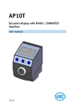
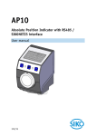
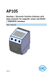
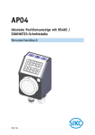
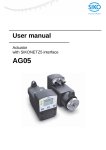
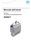
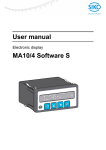
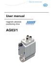
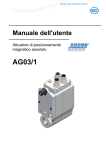
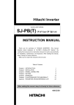
AP04 Absolute Position Indicator with RS485/SIKONETZ5 interface User manual 221/14 Table of contents 1 General Information .................................................................................................. 4 1.1 Documentation ........................................................................................................4 2 Display and Control Keys ............................................................................................ 4 2.1 General ...................................................................................................................4 2.2 LCD display ..............................................................................................................5 2.2.1 Extended display range ..........................................................................................5 2.3 LED display ..............................................................................................................5 2.4 Keys .......................................................................................................................5 3 Functional Description ............................................................................................... 6 3.1 Operating modes ......................................................................................................6 3.2 Position monitoring ..................................................................................................6 3.3 Loop positioning ......................................................................................................8 3.4 Parameterization of the position indicator ...................................................................9 3.4.1 Manual parameterization ........................................................................................9 3.4.1.1 Starting parameterization ...................................................................................9 3.4.1.2 Value input .......................................................................................................9 3.4.1.3 Value selection..................................................................................................9 3.4.1.4 Menu selection ................................................................................................ 10 3.4.1.5 Bus parameters ............................................................................................... 11 3.4.1.6 Positioning ..................................................................................................... 11 3.4.1.7 Visualization ................................................................................................... 13 3.4.1.8 Options .......................................................................................................... 14 3.4.2 Parameterization via interface .............................................................................. 14 4 Parameter description .............................................................................................. 15 5 Warnings / Errors..................................................................................................... 20 5.1 Warnings ............................................................................................................... 20 5.2 Errors.................................................................................................................... 20 6 System commands ................................................................................................... 21 6.1 Calibration ............................................................................................................ 21 6.2 Restore factory settings........................................................................................... 22 6.3 Alignment travel .................................................................................................... 22 7 Communication via Service Protocol .......................................................................... 23 7.1 General ................................................................................................................. 23 7.2 Error number encoding ............................................................................................ 23 7.3 System Status Word ................................................................................................ 23 7.4 Service protocol commands list................................................................................. 24 8 Communication via SIKONETZ5 ................................................................................. 28 8.1 Interface ............................................................................................................... 28 8.2 Data exchange ....................................................................................................... 28 AP04-RS485/SIKONETZ5 Date: 15.07.2014 Art. No. 86218 Mod. status 221/14 Page 2 of 38 8.3 8.3.1 8.3.2 8.3.3 8.3.4 8.3.5 8.3.6 8.3.7 8.4 8.5 8.5.1 8.6 8.7 8.7.1 8.7.2 8.8 8.9 8.9.1 8.9.2 Telegram setup....................................................................................................... 29 Command ........................................................................................................... 29 Node address ...................................................................................................... 29 Parameter address ............................................................................................... 29 Control word ...................................................................................................... 30 Status word ........................................................................................................ 30 Data .................................................................................................................. 31 Check sum.......................................................................................................... 31 Synchronization ..................................................................................................... 31 Error telegram ........................................................................................................ 32 SIKONETZ5 error codes ......................................................................................... 32 Errors.................................................................................................................... 33 Communication monitoring ...................................................................................... 33 Bus Timeout ....................................................................................................... 33 Programming interlock ......................................................................................... 33 Parameterization via SIKONETZ5 ............................................................................... 33 Examples of access ................................................................................................. 37 Example: Read parameter ..................................................................................... 37 Example: Write parameter ..................................................................................... 38 AP04-RS485/SIKONETZ5 Date: 15.07.2014 Art. No. 86218 Mod. status 221/14 Page 3 of 38 General Information 1 General Information 1.1 Documentation The following documents are associated with this document: The data sheet describes the technical data, the dimensions, the pin assignment, the accessories and the order key. The installation instructions describe the mechanical and electrical installation with all safety-relevant conditions and the associated technical specifications. The User manual for position indicator commissioning and integration into a fieldbus system. You can also download these documents at http://www.siko-global.com/en-de/servicedownloads. This manual is valid for software version V1.01 or newer! 2 Display and Control Keys 2.1 General The position indicator has a two-line display with special characters and three control keys. The keys serve for position indicator parameterization and control. One LED (1) serves for position monitoring. LED1 Fig. 1: Control elements AP04-RS485/SIKONETZ5 Date: 15.07.2014 Art. No. 86218 Mod. status 221/14 Page 4 of 38 Display and Control Keys 2.2 LCD display The The display range is limited to -19999 … 99999. Values outside this range are displayed with "". With supply voltage applied to the position indicator, the 1st line shows the actual position and the 2nd line shows the set point with factory settings. The values displayed are determined by the operating mode. Direction indicators (arrows) support positioning. The battery symbol is shown with a critical or insufficient battery status. With incremental measurement function activated, the incremental measurement symbol is shown. 2.2.1 Extended display range If values below -99999 are to be displayed, this can be realized by means of the control word, Bit3 in the operational mode with SIKONETZ5 protocol. If this bit is set and the value to be displayed is in the range between -19999 … -99999, then the negative sign and the figure with the highest value are blinking alternately. If the value range drops below -99999, "" will be displayed. 2.3 LED display In the basic state (factory setting), the LED has the following meaning: Actual position In target window1 Outside target window1 LED green red red green State on off on off Table 1: LED displays 2.4 Keys Pressing the key enables or disables the incremental measurement function. Pressing the key starts calibration (see chapter 6.1 Calibration) and acknowledges a pending error (see chapter 5.2 Errors). Pressing the key starts the parameterization mode (see chapter 3.4 Parameterization of the position indicator). AP04-RS485/SIKONETZ5 Date: 15.07.2014 Art. No. 86218 Mod. status 221/14 Page 5 of 38 Functional Description 3 Functional Description 3.1 Operating modes It is differentiated between the absolute position, differential value and Modulo operating modes. Operating mode Line 1 Line 2 Absolute position Actual position Set point Differential value Actual position Differential value Modulo Actual position Set point Table 2: Display with different operating modes Absolute position: Linear absolute position values are displayed. Differential value display: With factory setting: Differential value = actual position - set point (for calculating the differential value see chapter 4 Parameter description Parameter no. 32) Modulo display: Position values ranging from 0° to 360° are displayed. Using the "Decimal places" parameter (see Parameter no. 15) the resolution and the modulo point of the displayed values are set. Decimal places 0 1 2 3.2 Display resolution 1° 1/10° 1/100° Value range 0° … 360° 0,0° … 360,0° 0,00° … 360,00° Position monitoring (see chapter 3.3 Loop positioning) Arrows: (see chapter 4 Parameter description Parameter no. 18) Arrows are displayed to support the user with positioning as long as the current actual position value is outside (see chapter 4 Parameter description Parameter no. 27) target window1. The arrows represent the shaft's direction of rotation in order to arrive at the set point. A left-hand arrow means that the shaft is to be rotated counter-clockwise. A right-hand arrow requires clockwise rotation. In the modulo display operating mode, the shortest traveling distance to the set point is displayed. AP04-RS485/SIKONETZ5 Date: 15.07.2014 Art. No. 86218 Mod. status 221/14 Page 6 of 38 Functional Description Example: Operating mode = Modulo display Actual value = 5° Set point = 355° travel range shown: by (-)10° LED display: (see e. g. chapter 4 Parameter description Parameter no. 12) With factory setting, the LED glows green as long as the actual position is within the programmed window. When leaving target window1, the LED glows red. An additional target window (target window2) and an associated visualization can also be configured (see chapter 4 Parameter description Parameter no. 27, 28 and 29). System status word and SIKONETZ5 status word (see chapter 4 Parameter description Parameter no. 33): In the system status word, the dynamic and static target-window-reached bit is set upon reaching target window1 the dynamic bit is deleted when leaving target window1. The user must acknowledge the static bit. Example Position monitoring: Parameterization: Factory setting Additionally: Target window2 Visualization target window2 Set point = 15 =1 = 100 Positioning monitoring LED Target window 2 105 95 - 85 100 115 + Target window 1 Fig. 2: Positioning monitoring AP04-RS485/SIKONETZ5 Date: 15.07.2014 Art. No. 86218 Mod. status 221/14 Page 7 of 38 Functional Description 3.3 Loop positioning The LED display refers always to the actual set point, not to the loop value. Target window1 is also applied to the loop length. If the position indicator is operated on a spindle or an additional gear, the spindle or external gear backlash can be compensated by means of loop positioning. In this case, travelling to the target value is always from the same direction. This direction of approach can be defined. Example: The direction from which every target position shall be driven to is positive. Case 1 new position is greater than actual position: Direct travel to the target position. Case 2 new position is smaller than actual position: The position indicator's arrows show that the set point is to be overrun by the loop length. Afterwards, the set point is approached in positive direction. Loop length Positioning in positive direction - Positioning: loop + Positioning in negative direction + Set point Fig. 3: Positioning Loop + AP04-RS485/SIKONETZ5 Date: 15.07.2014 Art. No. 86218 Mod. status 221/14 Page 8 of 38 Functional Description 3.4 Parameterization of the position indicator The position indicator can be completely parameterized via the keys as well as via the bus interface. 3.4.1 Manual parameterization 3.4.1.1 Starting parameterization After applying supply voltage, the position indicator will be on the uppermost level of the menu structure (default/delivery state). By actuating the key, the set node address and baud rate is displayed. Parameterization starts after expiry of the release time (see chapter 4 Parameter description Parameter no. 9). 3.4.1.2 Value input With value input via the keys, the display range is limited to -19999 … 99999. When entering values beyond this range via SIKONETZ5 or the service protocol, "" will be displayed when you call up the parameter. Enter values via the key and the key. Confirm values entered by pressing the key. - decimal place selection key - Value input key 3.4.1.3 Value selection For some parameters you can select values from a list. Direct value input is not possible there. Pressing the key, the value can be selected from the list. By pressing the selection is confirmed. AP04-RS485/SIKONETZ5 Date: 15.07.2014 Art. No. 86218 Mod. status 221/14 key, the Page 9 of 38 Functional Description 3.4.1.4 Menu selection Start Hold down the key Key enable time expired? no yes Ending parameterization End Parameter Bus see menu Bus-Parameter Positioning parameter see menu Positioning parameter Visualization parameter see menu Visulaization parameter Parameter Options see menu Options Fig. 4: Menu selection AP04-RS485/SIKONETZ5 Date: 15.07.2014 Art. No. 86218 Mod. status 221/14 Page 10 of 38 Functional Description 3.4.1.5 Bus parameters Menu Parameter display Parameter no. acc. To chapter 4 3 4 5 6 36 Description Node address Value range: 0 - 31 Baud rate Selection: : 57600 baud : 115200 baud : 19200 baud Protocol Selection: : SIKONETZ5 : Service protocol Bus Timeout Value range: 0 - 20 Response delay Value range: 0 - 10 Table 3: Bus parameter menu 3.4.1.6 Positioning Menu Parameter display Parameter no. acc. To chapter 4 24 15 AP04-RS485/SIKONETZ5 Date: 15.07.2014 Description Readout per revolution / spindle pitch Value range: 0 - 59999 Decimal places Selection: : 0 : 0.1 : 0.02 : 0.003 : 0.0004 Art. No. 86218 Mod. status 221/14 Page 11 of 38 Functional Description Parameter display Parameter no. acc. To chapter 4 16 23 26 25 27 30 31 28 Description Display divisor Selection: : 1 : 10 : 100 : 1000 Sense of rotation Selection: : i sense of rotation (cw) : e sense of rotation (ccw) Calibration value Value range: -9999 … 9999 Selection: : no calibration : Execute calibration now Offset Value range: -9999 … 9999 Target window 1 Value range: 0 - 9999 Pos Type Selection: : direct : loop + : loop Loop length Value range: 0 - 9999 Target window 2 Value range: 0 - 9999 Table 4: Positioning menu AP04-RS485/SIKONETZ5 Date: 15.07.2014 Art. No. 86218 Mod. status 221/14 Page 12 of 38 Functional Description 3.4.1.7 Visualization Menu Parameter display Parameter no. acc. To chapter 4 19 13 12 14 29 18 20 Description Display orientation Selection: : 0° : 180° Green LED function Selection: : Indication of the operating status : Off Red LED function Selection: : Indication of the operating status : Off LED blinking function Selection: : LED blinking On : Off Visualization of target window 2 Selection: : target window 2 reached: Green LED : target window 2 reached: Red LED : Function off Direction indication function Selection: : On : inverted : Off Displayed value of 2nd display line Selection: : Set point : Off Table 5: Visualization menu AP04-RS485/SIKONETZ5 Date: 15.07.2014 Art. No. 86218 Mod. status 221/14 Page 13 of 38 Functional Description 3.4.1.8 Options Menu Parameter display Parameter no. acc. To chapter 4 9 11 10 32 8 Description Key enable time Value range: 1 … 60 Key function release for Reset (calibration) Selection: : Reset enabled via key : Reset disabled via key Key function enable for incremental measurement Selection: : Incremental measurement enabled via key : Incremental measurement disabled via key Formula for calculating the differential value Selection: : Differential value = actual position set point : Differential value = actual position actual position Operating mode of the display Selection: : Display of absolute actual position and set point : Display of absolute actual position and differential value : Display of angle values (0 … 360°) System commands Selection: : set all parameters to default (restore factory settings) : only standard parameters to default : only bus parameters to default : start equalization Table 6: Options menu 3.4.2 Parameterization via interface The position indicator can be completely parameterized in the SIKONETZ5 protocol via the RS485 interface (see chapter 8.8 Parameterization via SIKONETZ5). AP04-RS485/SIKONETZ5 Date: 15.07.2014 Art. No. 86218 Mod. status 221/14 Page 14 of 38 Parameter description 4 Parameter description Column S C P Explanation "S" = Parameter transferred is saved in the device non-volatilely "-" = Parameter transferred is saved in the device volatilely Parameter class 1 = Standard parameter 2 = Bus parameter Write access to the parameter can be locked via the "Configuation programming mode" parameter no 21. No. Name Default Description S C P - Absolute actual position - - - 2 Actual position Set point Selection / value Read only -999999 … 999999 1 0 - - P 3 Node address 0 … 31 1 4 Baud rate RS485 0…2 1 Absolute target position Can be displayed by the indicator: -19999 … 99999 SIKONETZ5: Setting the SIKONETZ5 node address Parameter changes become active only after cold start or software reset. Service protocol: no function Baud rate of the RS485 interface: 0 = 19200 1 = 57600 2 = 115200 Parameter changes become active only after cold start or software reset. 5 Protocol 0…1 0 Protocol of the RS485 interface: 0 = SIKONETZ5 1 = Service protocol Parameter changes become active only after cold start or software reset. S 2 P 6 Bus Timeout 0 … 20 0 SIKONETZ5: Bus Timeout values in x100 ms 0 = Function disabled (see chapter 8.7.1 Bus Timeout) Service protocol: no function S 2 P AP04-RS485/SIKONETZ5 Date: 15.07.2014 Art. No. 86218 Mod. status 221/14 S 2 P S 2 P Page 15 of 38 Parameter description No. Name Selection / value 0…2 Default Description S C P 7 Write reply parameter to set point 0 S 2 P Operating mode 0…2 0 SIKONETZ5: This parameter defines the reply to the Write set point command 0 = Set point 1 = Actual value 2 = Differential value Service protocol: no function Type of position value display 0 = absolute position display 1 = differential value 2 = Modulo (see chapter 3.1 Operating modes) 8 9 Key enable time 1 … 60 15 S 1 P 10 Key function enable Incremental measurement 0…1 1 11 Key function enable reset 0…1 1 Display / key control: Time in seconds how long the key must be held down until configuration starts Display / key control: 0 = incremental measurement function disabled 1 = incremental measurement function enabled Display / key control: 0 = Calibration (reset) function via key disabled 1 = Calibration (reset) function via key enabled 12 LED 1 red 0…1 1 Red LED 1 function: 0 = Off 1 = position-dependent display (On) If the position-dependent display for both LEDs is switched off the LEDs can be enabled by the control word (see chapter 8.3.4 Control word). S 1 P 13 LED 1 green 0…1 1 Green LED 1 function: 0 = Off 1 = position-dependent display (On) If the position-dependent display for both LEDs is switched off the LEDs can be enabled by the control word (see chapter 8.3.4 Control word). S 1 P 14 LED blinking 0…1 1 LED blinking function: 0 = LED display glows constantly (when On) 1 = LED display glows (when On) S 1 P AP04-RS485/SIKONETZ5 Date: 15.07.2014 Art. No. 86218 Mod. status 221/14 S 1 P S 1 P S 1 P Page 16 of 38 Parameter description No. Name Selection / value 0…4 Default Description S C P 15 Decimal places 0 S 1 P Display divisor 0…3 0 Display: Input of decimal places 0=0 1 = 0.0 2 = 0.00 3 = 0.000 4 = 0.0000 Display: Divisor by which the display accuracy is reduced compared with the measurement resolution. 0=1 1 = 10 2 = 100 3 = 1000 16 17 Display divisor application 0…1 0 S 1 P 18 Direction indication function 0…2 0 19 Display orientation 0…1 0 Display / transmission accuracy: 0= The display divisor is applied to the set point and actual position of interface and display unit. 1= The display divisor is only applied to the display unit. The values are transferred via the interface with undivided resolution. Display: The direction indicators show the direction of shaft adjustment required to arrive at the set target window 1. 0 = On 1 = inverted 2 = Off Display: Display orientation 0 = 0° 1 = rotated by 180° 20 Displayed value 2nd display line 0…1 0 Display: Parameter to be displayed in the 2nd line of the display. 0 = set point 1 = OFF S 1 P 21 Programming mode configuration 0…1 0 SIKONETZ5: 0 = programming not locked 1 = locking of programming depends on the programming mode Service protocol: no function S 1 P AP04-RS485/SIKONETZ5 Date: 15.07.2014 Art. No. 86218 Mod. status 221/14 S 1 P S 1 P S 1 P Page 17 of 38 Parameter description No. Name Selection / value 0…1 Default Description S C P 22 Programming mode 0 - 1 - Sense of rotation i, e i SIKONETZ5: 0 = Programming mode Off 1 = Programming mode On Service protocol: no function Counting direction of the measuring system: With shaft rotating clockwise (view on the LCD) i sense of rotation (cw): positive counting direction e sense of rotation (ccw): negative counting direction 23 24 APU / Spindle pitch 0 … 59999 720 S 1 P 25 Offset -9999 … 9999 0 26 Calibration value -9999 … 9999 0 Readout per revolution / spindle pitch: Position value is output in x increments per revolution. Offset value: Changes to the offset value are considered in the calculation of the position value immediately after value entry / transmission. The following equation is applied in case of calibration: Position value = 0 + calibration value + offset value Calibration value: Changes to the calibration value are adopted for calculation of the position value (via key or S command) only after calibration). Then one has: Position value = 0 + calibration value + offset value 27 Target window1 0 … 9999 5 Positioning window1: The target position has been reached when the indicator's actual position is within the programmed set point ± this window. With factory settings, this is represented as follows: LCD: no arrows LED display LED1 = green System status word or status word: Setting the corresponding bits. S 1 P AP04-RS485/SIKONETZ5 Date: 15.07.2014 Art. No. 86218 Mod. status 221/14 S 1 P S 1 P S 1 P Page 18 of 38 Parameter description No. Name Selection / value 0 … 9999 Default Description S C P 28 Target window 2 0 Positioning window2: Additional target window for detecting an approach to target window1 (see also Parameter no. 29 and chapter 3.2 Position monitoring seq.). S 1 P 29 Visualization of target window2 0…2 0 Visualization of the "target window2 reached" state Selection: 0 = Off 1 = LED1 glows green 2 = LED1 glows red If the actual position is inside target window2, but outside target window1, the LED display glows as set here. Additionally, blinking of the LED is inverted to Parameter no. 14: LED blinking switched on. S 1 P 30 Positioning mode 0…2 direct Type of positioning: 0 = direct: direct travelling from actual position to set point possible. 1 = loop +: travelling to the set point must always be in positive direction to compensate for spindle play. 2 = loop -: travelling to the set point must always be in negative direction to compensate for spindle play. S 1 P 31 Loop length 0 … 9999 0 S 1 P 32 Differential value calculation 0…1 0 33 System Status Word Read only - Loop length: see chapter 3.3 Loop positioning Calculation of the differential value: 0 Differential value = actual position - set point 1: Differential value = actual position - actual position System Status Word see chapters 7.3 System Status Word and 8.3.5 Status word 34 Voltage of battery Read only - - - - 35 Software version Read only - Battery voltage: Values in 1/100 V Software version AP04-RS485/SIKONETZ5 Date: 15.07.2014 Art. No. 86218 Mod. status 221/14 S 1 P - - - S - - Page 19 of 38 Warnings / Errors No. Name 36 Response delay Selection / value 0 … 10 Default Description S C P 0 Response delay: 0: no delay 1 … 10: number of internal program cycles waited until an SN5-bus telegram is replied to. Thus, the response to a telegram can be delayed until the master is ready to receive. The value 10 corresponds to a delay of approx. 5 ms. S 2 P Table 7: Parameter description 5 Warnings / Errors 5.1 Warnings Warnings do not influence the acquisition of the absolute position value. Warnings are deleted after removing the cause. Possible warnings: Battery voltage for absolute position detection is below limit immediately exchange battery. This warning is displayed with a blinking battery symbol and in the system status word or status word (see chapter 7.3 System Status Word and accoordingly chapter 8.3.5 Status word). 5.2 Errors Error states are signalled via display and interface. Pending errors can be read via the interface. For returning to normal operation, the errors must be acknowledged or deleted via the key or bus interface. (For signaling and acknowledging in the service protocol see chapter 7.3 System Status Word and accoordingly SIKONETZ5 chapter 8.3.4 and 8.3.5 Status word.) Display Error code SIKONETZ5 Error 0x0000 Bit assignment in the system status word or status word - 11+7 2+7 Low battery voltage 0x0006 0x0019 0x0080 7 Check sum SIKONETZ5 0x0081 7 Timeout SIKONETZ5 0x0082 7 Value range exceeded / inappropriate 0x0182 7 Value exceeds lower limit AP04-RS485/SIKONETZ5 Date: 15.07.2014 No error Speed exceeded Art. No. 86218 Mod. status 221/14 Page 20 of 38 System commands Display Error code SIKONETZ5 Error 0x0282 Bit assignment in the system status word or status word 7 0x0083 7 Unknown parameter 0x0084 7 Access not supported 0x0184 7 Write on read only 0x0284 7 Read on write only 0x0085 7 Error caused by device status 0x0385 7 Programming lock activated Value exceeds upper limit Table 8: Error messages Display Error Battery empty Possible effect Position value not reliable Speed exceeded Position value not reliable Corrective actions Battery change + calibration travel Reduce speed + calibration travel Table 9: Corrective actions 6 System commands 6.1 Calibration Two steps are required for executing calibration: 1. Enter/write calibration value (see chapter 3.4.1.6 Positioning and chapter 8 Communication via SIKONETZ5 Parameter address 0x1F) 2. Execute calibration (reset) (see chapter 2.4 Keys, chapter 3.4.1.6 Positioning or chapter 8 Communication via SIKONETZ5 Parameter address 0xA0) Since the measuring system is an absolute system, calibration is necessary only once with commissioning. With calibration, the calibration value is adopted for calculation of the position value. The following equation is applied in case of calibration: Position value = 0 + calibration value + offset value Calibration value (see chapter 4 Parameter description Parameter no. 26) Offset value (see chapter 4 Parameter description Parameter no. 25) AP04-RS485/SIKONETZ5 Date: 15.07.2014 Art. No. 86218 Mod. status 221/14 Page 21 of 38 System commands 6.2 Restore factory settings In some instance, for instance for evaliuating the position indicator, it may be useful to restore the device's factory settings. This may de done as follows: Access Manually Coding Service protocol S SIKONETZ5 0xA0 Factory settings are restored all parameters only standard parameters only bus parameters 11100 11101 11102 1 2 5 all parameters only standard parameters only bus parameters all parameters only standard parameters only bus parameters Table 10: Access to factory settings 6.3 Alignment travel The position indicator is aligned in the factory and is, therefore, fully functioning. The following steps must be carried out for additional alignment: 1. Start alignment (see Table 11: Start access to alignment) The following is displayed: The value can vary by +/- 1. 2. Rotate the position indicator's shaft counter-clockwise at the speed of << 1 rpm . The value will slowly change until 103. 3. If this value is finally exceeded, the alignment process will be completed. The position indicator enters normal operation, which is shown on the display unit. 4. Calibrate the position indicator (see chapter 6.1 Calibration) It is not unusual that the position value cannot be displayed at first following alignment travel and "" displayed instead. The correct value will be displayed after calibration. Alignment can be started as follows. Access Manually Coding Service protocol SIKONETZ5 S 0xC3 00100 1 Table 11: Start access to alignment AP04-RS485/SIKONETZ5 Date: 15.07.2014 Art. No. 86218 Mod. status 221/14 Page 22 of 38 Communication via Service Protocol 7 Communication via Service Protocol 7.1 General The service protocol enables parameterization and control of the position indicator via ASCII commands. No additional devices must be connected to the RS485 interface since this protocol is not bus-compatible. An ASCII terminal sends a letter and additional parameters if required (ASCII). Subsequently, the position indicator sends a reply with a concluding <CR>. Available baud rates: Additional settings: 7.2 19.2 kBit / 57.6 kBit (factory setting) / 115.2 kBit No parity, 8 data bits, 1 stop bit, no handshake Error number encoding The following error messages are returned with faulty entries. Error number ?1 ?2 Description input of illegal parameter number illegal value range Table 12: Error number encoding 7.3 System Status Word The system status word consists of 2 bytes and reflects the state of the actuator. High Byte Low Byte Bit number 15 14 13 12 11 10 9 8 7 6 5 0 0 1 0 1 0 0 1 0 1 0 2 9 4 4 0 3 1 2 0 1 0 0 0 8 Fig. 5: Structure of system status word Example (grey background): binary: hex: 0010 1001 0100 1000 2 9 4 8 The table below informs about the meaning of the individual bits: Bit 0 1 2 3 4 5 Meaning direction indication ">" direction indication "<" Speed error Target window2 dynamic Target window1 static Target window1 dynamic AP04-RS485/SIKONETZ5 Date: 15.07.2014 Value = 0 off off not present not reached never reached not reached Art. No. 86218 Value = 1 on on speed is or was too high reached is or was reached reached Mod. status 221/14 Page 23 of 38 Communication via Service Protocol Bit 6 Meaning Deviation Value = 0 Actual position < = set point not present 7 Error 8 9 Position value output Position value = incremental measurement reserved Battery status (warning) reserviert Value = 1 Actual position >set point dynamic off present The cause of the error must be removed and acknowledged. freezed on key all right not actuated critical actuated 14 key not actuated actuated 15 key not actuated actuated 10 11 12 13 Table 13: System Status Word 7.4 Service protocol commands list Command Length Reply Description Ay 2/17 "AP04_SN5_ zWVxxx>" Device type / software version y=0: hardware version; z = H y=1: software version; z = S By 2/10 dez "±xxxxxxx>" Ey 2/11 "±xxxxxxxx>" Diagnosis y=3: Battery voltage [1/100 V] Output values ±xxxxxxxx = decimal value in increments y=0: Current set point y=1: Position with incremental measurement formation y=2: Position with calibration y=3: Calibration value y=5: Offset Enter values ±xxxxxxxx decimal value in increments y=0: Target position (volatile) y=3: Calibration value y=5: Offset Fy±xxxxxxxx 11/2 AP04-RS485/SIKONETZ5 ">" Date: 15.07.2014 Art. No. 86218 Mod. status 221/14 Parameter no.acc. to chapter 4 35 34 2 26 25 2 26 25 Page 24 of 38 Communication via Service Protocol Command Length Reply Description Gyy 3/7 "xxxxx>" Output 2-byte value yy = Address xxxxx = decimal value yy=00: APU / spindle pitch yy=01: Display divisor 0=1 1 = 10 2 = 100 3 = 1000 yy=02: Display divisor application yy=03: Decimal places 0=0 1 = 0.0 2 = 0.00 3 = 0.000 4 = 0.0000 yy=04: Target window 1 yy=05: Target window 2 yy=06: Visualization of target window2 yy=07: Positioning mode yy=08: Loop length yy=09: Direction indication function 0 = On 1 = inverted 2 = Off yy=10: Key enable time Range 1 – 60 seconds yy=11: Key function enable reset (Calibration) 0 = Function disabled via key 1 = Function enabled via key yy=12: Key function enable incremental measurement 0 = Function disabled via key 1 = Function enabled via key yy=13: Display orientation 0 = 0° 1 = rotated by 180° yy=14: LED blinking 0 = Off 1 = On yy=15: reserviert yy=16: LED red 0 = Off 1 = On AP04-RS485/SIKONETZ5 Date: 15.07.2014 Art. No. 86218 Parameter no.acc. to chapter 4 Mod. status 221/14 24 16 17 15 27 28 29 30 31 18 9 11 10 19 14 12 Page 25 of 38 Communication via Service Protocol Command Length Reply Description yy=17: LED green 0 = Off 1 = On yy=18: Displayed value 2nd display line 0 = set point 1 = Off yy=19: Differential value calculation 0: Differential value = actual position – set point 1: Differential value = set point – actual position yy=20: reserved yy=21: Baud rate RS485 0 = 19200 1 = 57600 2 = 115200 yy=22: Node address yy=23: Response delay Hyyxxxxx AP04-RS485/SIKONETZ5 8/2 ">" Date: 15.07.2014 Enter 2-byte value yy = Address xxxxx = decimal value yy=00: APU / spindle pitch yy=01: Display divisor yy=02: Display divisor application yy=03: Decimal places yy=04: Target window 1 yy=05: Target window 2 yy=06: Visualization of target window2 yy=07: Positioning mode yy=08: Loop length yy=09: Direction indication function yy=10: Key enable time yy=11: Key function enable reset (Calibration) yy=12: Key function enable incremental measurement yy=13: Display orientation yy=14: LED blinking yy=15: reserved yy=16: LED red yy=17: LED green Art. No. 86218 Mod. status 221/14 Parameter no.acc. to chapter 4 13 20 32 4 3 36 24 16 17 15 27 28 29 30 31 18 9 11 10 19 14 12 13 Page 26 of 38 Communication via Service Protocol Command Length Reply Description yy=18: Displayed value 2nd display line yy=19: Differential value calculation yy=20: reserved yy=21: Baud rate RS485 yy=22: Node address yy=23: Response delay Software reset K 1/2 ">" L 1/2 ">" Calibration (see chapter 6.1 Calibration) R 1/2 "xy" Sxxxxx 6/2 ">" Ty 2/2 ">" Output system status word (hex) for the meaning of the individual bits see Table 13: System Status Word x = High Byte y = Low Byte Reset device to basic state / System commands x=00100: Start alignment (see chapter 6 System commands) x=11100: all parameters into basic state Caution! All parameter classes will be reset. After restart, the factory settings will be active, this applies to bus protocol and baud rate as well. x=11101: only standard parameters into basic state x=11102: only bus parameters into basic state x=11103: Acknowledge error x=11104: Acknowledgement target window1 static (description see chapter 3.2 Position monitoring) x=11105: activate bootloader Enter sense of rotation y=0: i sense of rotation (cw) y=1: e sense of rotation (ccw) AP04-RS485/SIKONETZ5 Date: 15.07.2014 Art. No. 86218 Mod. status 221/14 Parameter no.acc. to chapter 4 20 32 4 3 36 - 23 Page 27 of 38 Communication via SIKONETZ5 Command Length Reply Description Parameter no.acc. to chapter 4 U 1/11 "aabbccdxyz" Output sensor data aa = ADC-Sin bb = ADC-Cos cc = fine value d = quarter x = rough value [2] y = rough value [1] z = rough value [0] Xy 2/2 ">" Enter operation mode 0 = absolute position display 1 = differential value 2 = Modulo 8 Z 1/11 "±xxxxxxxx>" Output actual position 1 Table 14: Service protocol commands list 8 Communication via SIKONETZ5 8.1 Interface RS485 interface Available baud rates: 19.2 kBit / 57.6 kBit (Factory setting) / 115.2 kBit No parity, 8 data bits, 1 stop bit, no handshake 8.2 Data exchange The protocol functions according to the master – slave principle. The actuator acts as a slave. Every instance of communication must be initiated by the master. When the master has sent a command telegram, the slave sends a reply telegram. Broadcast commands are an exception, they remain always unanswered by the slave. The protocol is optimized for cyclical data exchange. The relevant data such as set point and actual value as well as control and status words can be transferred between master and slave by a single telegram exchange. The parameter to be returned by the slave as a reply to the master's Write set point command can be defined via the "Write set point reply parameter". AP04-RS485/SIKONETZ5 Date: 15.07.2014 Art. No. 86218 Mod. status 221/14 Page 28 of 38 Communication via SIKONETZ5 8.3 Telegram setup Control word (CW), status word (SW) and data are transferred in the Big-Endian format. Command telegram (from master) 1stbyte 2ndbyte 3rdbyte Command Node address Parameter address 4thbyte 5thbyte 6thbyte High Byte Low Byte MSB CW 7thbyte 8thbyte 9thbyte LSB 10thbyte Check sum Data Reply telegram from slave 1stbyte 2ndbyte 3rdbyte Reply Node address Parameter address 4thbyte 5thbyte 6thbyte High Byte Low Byte MSB SW 8.3.1 7thbyte 8thbyte 9thbyte LSB 10thbyte Check sum Data Command The following access types are provided by SIKONETZ5. 8.3.2 Access code 0x00 Meaning read 0x01 write 0x02 broadcast Description The master requests the addressed slave to output the relevant value in a response telegram. The master requests the addressed slave to accept the value transferred in the same telegram. The master requests all connected slaves to execute the command transferred in the same telegram. Node address The device address can be freely set in the range of 0 to 31. The delivered devices are preset to node address 1 ex works and must be reset to the desired address to enable their operation with multiple slaves on the SIKONETZ5 fieldbus. Each address can be assigned in the fieldbus only once! Description see chapter 4 Parameter description Parameter no. 3. 8.3.3 Parameter address A distinct address is assigned to every parameter (e.g. calibration value) or functional value (e. g. set point). Description see chapter 8.8 Parameterization via SIKONETZ5. AP04-RS485/SIKONETZ5 Date: 15.07.2014 Art. No. 86218 Mod. status 221/14 Page 29 of 38 Communication via SIKONETZ5 8.3.4 Control word The master can give the following commands to the slave in the control word (CW). Bit 0 1 2 3 4 5 6 7 8 9 10 11 12 13 14 15 Meaning reserved reserved reserved Display range 1 Acknowledgment target window1 static 2 Error reserved reserved reserved reserved reserved reserved LED green LED red reserved LED blinking Value = 0 ever 0 ever 0 ever 0 standard not acknowledged Value = 1 extended acknowledged not acknowledged ever 0 ever 0 ever 0 ever 0 ever 0 ever 0 OFF OFF ever 0 OFF acknowledged ON 3 ON 3 ON 3 Table 15: Control word (Master Slave) SIKONETZ5 8.3.5 Status word The current status of the slave is transferred to the master in the status word (SW). Bit 0 1 2 Meaning Direction indication ">" Direction indication "<" Speed error Value = 0 OFF OFF is / was not present 3 4 5 6 Target window2 dynamic Target window1 static 4 Target window1 dynamic 4 Deviation 7 8 General error Output of position value 5 not reached never reached not reached Actual position <= set point not present dynamic Value = 1 ON ON max. speed is / was exceeded reached reached reached actual position > set point is present freezed 1 see chapter 2.2.1 Extended display range see status word bit SW 4: "Target window1 static" 3 In order to get access to the LED via the control word, the position-dependent function must be inactivated viaParameter no. 12, 13 and 14. 4 The bit SW.4: "Target window1 static" is set when target window1 was reached. It is not deleted when leaving the window. Deletion occurs via acknowledgment with bit CW.4. Bit SW.5 is deleted automatically upon leaving the window. 5 see chapter 8.8: Parameter address 0xAA. 2 AP04-RS485/SIKONETZ5 Date: 15.07.2014 Art. No. 86218 Mod. status 221/14 Page 30 of 38 Communication via SIKONETZ5 Bit 9 Value = 0 OFF Value = 1 ON key all right not actuated critical actuated 14 key not actuated actuated 15 key not actuated actuated 10 11 12 13 Meaning Position value = incremental measurement reserved for future use Battery status (warning) reserved for future use Table 16: Status word (Slave Master) SIKONETZ5 8.3.6 Data Range for data exchange. Size: 4 bytes. 8.3.7 Check sum For checking error-free data transfer, a check sum is formed at the end of the telegram. The check sum is the exclusive-OR-link of bytes 1 … 9: Check sum [Byte10] = [Byte1] XOR [Byte2] XOR [Byte3] XOR [Byte4] XOR [Byte5] XOR [Byte6] XOR [Byte7] XOR [Byte8] XOR [Byte9] The following applies for checking the telegram received: [Byte1] XOR [Byte2] XOR [Byte3] XOR [Byte4] XOR [Byte5] XOR [Byte6] XOR [Byte7] XOR [Byte8] XOR [Byte9] XOR [Byte 10] = 0 With a result unequal 0 a transmission error is to be assumed. 8.4 Synchronization Processing of the "Restore factory settings" system command may take up to 100 ms. Acknowledgment is reported only after proper updating of all parameters in the non-volatile memory. Byte/telegram synchronization is via "Timeout". The intervals between the individual bytes of a telegram must not exceed the value of 10 ms. If an addressed device does not respond, the master must not send another telegram earlier than after 30 ms. AP04-RS485/SIKONETZ5 Date: 15.07.2014 Art. No. 86218 Mod. status 221/14 Page 31 of 38 Communication via SIKONETZ5 8.5 Error telegram Illegal entries are replied with an error telegram. An error telegram consists of parameter address 0xFD and an error code. The error code is in the data section of the reply telegram. The error code is divided in two bytes. Code 1 describes the error proper, code 2 contains additional information if available. In the following example an attempt was made at writing a value of 90 to the key enable time parameter address. However, a maximum value of only 60 is admissible for this parameter. Telegram from master to slave 1stbyte 2ndbyte 3rdbyte Command Node address Parameter address 0x01 0x01 0x04 4thbyte 5thbyte 6thbyte 7thbyte CW 8thbyte 9thbyte Data 10thbyte Check sum 0x00 0x00 0x00 0x00 0x00 0x5A 0x5E 4thbyte 5thbyte 6thbyte 7thbyte 8thbyte 9thbyte 10thbyte Code 2 Code 1 Check sum 0x02 0x82 0xFC Reply telegram from slave 8.5.1 1stbyte 2ndbyte 3rdbyte Command Node address Parameter address 0x01 0x01 0xFD SW 0x00 Data 0x81 0x00 0x00 SIKONETZ5 error codes Code 1 0x80 0x81 0x82 Description Check sum SIKONETZ5 Timeout SIKONETZ5 Value rage exceeded / inadequate 0x83 0x84 Unknown parameter Access is not supported 0x85 Error due to device status Code 2 0x00 0x00 0x00 0x01 0x02 0x00 0x00 0x01 0x02 0x00 0x03 Description no further information available no further information available no further information available Value < MIN Value > MAX no further information available no further information available write attempt to read only read attempt to write only no further information available Programming locked Table 17: SIKONETZ5 error codes AP04-RS485/SIKONETZ5 Date: 15.07.2014 Art. No. 86218 Mod. status 221/14 Page 32 of 38 Communication via SIKONETZ5 8.6 Errors If a slave is in the error state the slave signals the error with SW.7 = 1. An error must be acknowledged by CW.5 = 0/1 or by pressing the key. If the cause of the error has not been resolved at the time of acknowledgment, the error will not be reset or triggered anew, resp. Errors that have not been acknowledged can be read via a read command on Parameter address 0xFD. The error code will be output (see chapter 5.2 Errors and 8.5.1 SIKONETZ5 error codes). 8.7 Communication monitoring 8.7.1 Bus Timeout Bus timeout monitoring is activated via parameterization of a valid time value (>0) for timeout (see chapter 4 Parameter description Parameter no. 6). The first telegram received by the slave starts time monitoring. Every new telegram recognized as valid by a slave (correct check sum) triggers time monitoring. If timeout occurs, this will result in the Timeout error. After establishing cyclic communication between master and slave, this function can detect a broken cable of the connection line for instance and signal the defect. 8.7.2 Programming interlock Programming interlock is controlled via Parameter no. 21 "Programming mode configuration" This parameter being enabled, the interlock must be canceled prior to write access to a lockable parameter (see Table 7: Parameter description) by applying a write access to Parameter no. 22: "Programming mode". Correspondingly, the interlock should be enabled again immediately after a write access. This mechanism enhances protection against unintentional parameterization. Write access to locked parameters is replied with "Error due to device state" (see chapter 8.5.1 SIKONETZ5 error codes). 8.8 Parameterization via SIKONETZ5 On principle, the position indicator sends a telegram acknowledging write and read commands of the master. With the command executable the value adopted is in the reply telegram. If the actuator was unable to execute the command, e. g. because it attempted to write a value beyond the admissible range, the position indicator will send an error telegram in reply. Access rw = read write ro = read only wo = write only AP04-RS485/SIKONETZ5 Date: 15.07.2014 Art. No. 86218 Mod. status 221/14 Page 33 of 38 Communication via SIKONETZ5 Parameter Access Format Description no.acc. to Adr. chapter 4 [hex] 3 0x00 Node address rw Unsigned8 4 0x01 Baud rate rw Unsigned8 6 0x02 Bus Timeout rw Unsigned16 7 0x03 rw Unsigned8 9 0x04 rw Unsigned8 11 0x05 Reply parameter to write set point command Enable keys time Key function enable reset Value range 0 … 31 Parameter changes become active only after cold start or software reset. 0 = 19200 1 = 57600 2 = 115200 Parameter changes become active only after cold start or software reset. Value range 0 … 20 (see chapter 8.7.1 Bus Timeout) 0 = Set point 1 = Actual position 2 = Differential value Value range 1 … 60 rw Unsigned8 14 0x06 LED blinking rw Unsigned8 12 0x08 LED 1 red rw Unsigned8 13 0x09 LED 1 green rw Unsigned8 15 0x0A Decimal places rw Unsigned8 16 0x0B Display divisor rw Unsigned8 18 0x0C Direction indication function rw Unsigned8 19 0x0D Display orientation rw Unsigned8 AP04-RS485/SIKONETZ5 Name Date: 15.07.2014 Art. No. 86218 0 = key function locked 1 = Calibration (reset) key function enabled 0 = LED display glows constantly 1 = LED display blinks 0 = LED 1 red Off 1 = LED 1 red On 0 = LED 1 green Off 1 = LED 1 green On Value range 0 … 4 0=0 1 = 0.0 2 = 0.00 3 = 0.000 4 = 0.0000 Value range 0 … 3 0=1 1 = 10 2 = 100 3 = 1000 Value range 0 … 2 0 = on 1 = inverted 2 = off 0 = normal 1 = rotated by 180° Mod. status 221/14 Page 34 of 38 Communication via SIKONETZ5 Parameter Name no.acc. to Adr. chapter 4 [hex] 21 0x0E Programming mode Configuration 23 0x1B Sense of rotation 24 0x1C APU / Spindle pitch 25 0x1E Offset 26 0x1F Calibration value 27 0x20 Target window1 30 0x21 Positioning mode Access Format Description rw Unsigned8 0 = no programming mode 1 = apply programming mode rw Unsigned8 rw Unsigned16 0 = i sense of rotation (cw) 1 = e sense of rotation (ccw) Value range 0 … 59999 rw rw Integer32 Integer32 Value range -9999 … 9999 Value range -9999 … 9999 rw rw Unsigned16 Unsigned8 Value range 0 … 9999 0 = direct 1 = loop + 2 = loop Value range 0 … 9999 0 = absolute position display 1 = differential value 2 = Modulo 0 = set point 1 = OFF Value range 0 … 9999 0 = OFF 1 = LED 1 glows green 2 = LED 1 glows red 0 = application to display and interface 1 = application to display only 0 Diff. = actual position - set point 1 Diff. =set point - actual position 0 = key function disabled 1 = incremental measurement key function enabled Output of voltage [1/100 V] 31 8 0x22 0x28 Loop length Operating mode rw rw Unsigned16 Unsigned8 20 0x30 rw Unsigned8 28 29 0x31 0x32 Displayed value 2nd display line Target window2 Target window2 – visualization rw rw Unsigned16 Unsigned16 17 0x33 Display divisor application rw Unsigned8 32 0x34 Differential value calculation rw Unsigned8 10 0x35 rw Unsigned8 34 0x63 ro Integer16 35 0x65 0x67 Key function enable incremental measurement Voltage of battery Device code Software version ro ro Unsigned8 Unsigned16 AP04-RS485/SIKONETZ5 Date: 15.07.2014 Art. No. 86218 1 = AP04 Versions number Bx.: 101dec corresponds to V1.01 Mod. status 221/14 Page 35 of 38 Communication via SIKONETZ5 Parameter Name no.acc. to Adr. chapter 4 [hex] 0xA0 S command 36 AP04-RS485/SIKONETZ5 Access Format Description wo Unsigned16 1 = all parameters to default Caution! All parameter classes will be reset. After restart, the factory settings will be active, this applies to node address and baud rate as well. 2 = only standard parameters to default 5 = bus parameters to default 7 = calibration 9 = software reset Programming interlock depending on the parameter "Configuration programming mode" 0 = Programming mode Off: Write parameter disabled. Write attempts are acknowledged with an error message. 1 = Programming mode On: Write parameter enabled (see chapter 8.7.2 Programming interlock) 1 = Freeze actual position: The current actual value is cached until next reading of the actual position (see chapter 6.3 Alignment travel) Configuration of bus protocol 0 = SIKONETZ5 1 = Service protocol Parameter changes become active only after cold start or software reset. Response delay: 0: no delay 1 … 10: number of program cycles (see chapter 8.3.5 Status word) (see chapter 3.1 Operating modes) 0xA8 Programming mode On / Off temporary wo Unsigned8 0xAA Freeze actual position wo Unsigned8 0xC3 Start alignment wo Unsigned8 0xCA Switching the bus protocol wo Unsigned8 0xD0 Response delay rw Unsigned8 0xFA Status word ro Unsigned16 0xFC Differential value ro Integer32 Date: 15.07.2014 Art. No. 86218 Mod. status 221/14 Page 36 of 38 Communication via SIKONETZ5 Parameter Name Access no.acc. to Adr. chapter 4 [hex] 0xFD Error Format Description Integer32 (see chapter 8.5 Error telegram) Actual position (see chapter 3.1 Operating modes) Set point 0xFE Actual position ro Integer32 0xFF Set point rw Integer32 Table 18: Parameter description SIKONETZ5 8.9 Examples of access 8.9.1 Example: Read parameter With read commands the data range shall be set to value 0. Reading the parameter target window1 of node address 1: Read command: 0x00 Node address: 0x01 Parameter address: 0x20 Target window1 Data: 0x00 00 00 00 Telegram from master to slave 1stbyte 2ndbyte 3rdbyte Command Node address Parameter address 0x00 0x01 0x20 4thbyte 5thbyte 6thbyte 7thbyte CW 8thbyte 9thbyte Data 10thbyte Check sum 0x00 0x00 0x00 0x00 0x00 0x00 0x21 4thbyte 5thbyte 6thbyte 7thbyte 8thbyte 9thbyte 10thbyte Reply telegram from slave 1stbyte 2ndbyte 3rdbyte Command / Reply Node address Parameter address 0x00 0x01 0x20 AP04-RS485/SIKONETZ5 Date: 15.07.2014 SW 0x00 0x01 Art. No. 86218 Data 0x00 0x00 0x00 Mod. status 221/14 Check sum 0x05 0x25 Page 37 of 38 Communication via SIKONETZ5 8.9.2 Example: Write parameter Set parameter offset value of node address 1 to value 500: Write command: 0x01 Node address: 0x01 Parameter address: 0x1E Offset value Data: 0x00 00 01 F4 500dec Telegram from master to slave 1stbyte 2ndbyte 3rdbyte Command Node address Parameter address 0x01 0x01 0x1E 4thbyte 5thbyte 6thbyte 7thbyte CW 8thbyte 9thbyte Data 10thbyte Check sum 0x00 0x00 0x00 0x00 0x01 0xF4 0xEB 4thbyte 5thbyte 6thbyte 7thbyte 8thbyte 9thbyte 10thbyte Reply telegram from slave 1stbyte 2ndbyte 3rdbyte Command / Reply Node address Parameter address 0x01 0x01 0x1E AP04-RS485/SIKONETZ5 Date: 15.07.2014 SW 0x00 0x01 Art. No. 86218 Data 0x00 0x00 0x01 Mod. status 221/14 Check sum 0xF4 0xEA Page 38 of 38