1
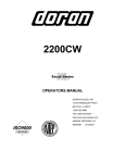
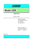
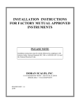
Model PC-400
Portion Control Scale
Operator’s Manual
Doran Scales, Inc.
1315 Paramount Pkwy
Batavia, IL 60510
1-800-262-6844
www.doranscales.com
Man. #233 Manual Revision 0.1
i
Table of Contents
Section 1. Unpacking and Installation ..................................................... 1
Unpacking: ................................................................................................................................................................1
Installation: ................................................................................................................................................................1
Electrical Connections:..............................................................................................................................................1
Care & Cleaning: .......................................................................................................................................................1
Section 2. Scale Operations Guide ......................................................... 2
Display Functions:.....................................................................................................................................................2
Basic Weighing: ........................................................................................................................................................2
Units Select:...............................................................................................................................................................2
Battery: ......................................................................................................................................................................2
Power:........................................................................................................................................................................2
Section 3. Setup and Calibration Guide.................................................. 3
Power connections:....................................................................................................................................................3
RS-232 Connections:.................................................................................................................................................3
Calibration and Parameter Setup: ..............................................................................................................................3
Analog Setup: ............................................................................................................................................................4
Section 4. Battery...................................................................................... 5
Charging: ...................................................................................................................................................................5
Replacement: .............................................................................................................................................................5
Voltage Levels:..........................................................................................................................................................5
Battery Voltages.........................................................................................................................................................5
Section 5. Parameter Setup ..................................................................... 6
Entering and Exiting Setup Mode: ............................................................................................................................6
Changing a Parameter:...............................................................................................................................................6
Changing Start up Units: ...........................................................................................................................................6
Legal for Trade Restrictions: .....................................................................................................................................6
Section 6. Setup Menus Explained.......................................................... 7
Resoluton (divisions) Setup Menu.............................................................................................................................7
Capacity Setup Menu.................................................................................................................................................7
Calibration Menu(s)...................................................................................................................................................7
Auto Off Mode ..........................................................................................................................................................8
Auto Zero Tracking ...................................................................................................................................................8
Motion Aperture ........................................................................................................................................................8
Start Up Zero .............................................................................................................................................................8
Data Output ...............................................................................................................................................................9
Data Format ...............................................................................................................................................................9
Baud Rate ..................................................................................................................................................................9
Convert Select ...........................................................................................................................................................9
Startup Units............................................................................................................................................................10
Operation Mode.......................................................................................................................................................10
Raw Counts .............................................................................................................................................................10
Section 7. Data Communications .......................................................... 11
Introduction to data communications: .....................................................................................................................11
Printer Modes: .........................................................................................................................................................12
Data Output Format:................................................................................................................................................13
Bi-directional Communications:..............................................................................................................................16
RS232 Pin-outs:.......................................................................................................................................................16
Section 8. Specifications......................................................................... 17
Section 9. Troubleshooting.................................................................... 18
ii
Section 1. Unpacking and Installation
Unpacking:
Before unpacking your Doran scale, please read the instructions in this
section. Your new scale is a durable industrial product, but it is also a
sensitive weighing instrument. Normal care should be taken when
handling and using this product. Improper handling or abuse can
damage the scale and result in costly repairs that may not be covered by
the warranty. If you notice any shipping damage, notify the shipper
immediately. Please observe the following precautions to insure years
of trouble free service from your new scale.
! DO NOT drop the scale.
! DO NOT immerse the scale.
! DO NOT drop objects on the scale.
Carefully remove the scale from the shipping carton. Be sure to retain
all shipping materials in case the scale must be shipped elsewhere.
Installation:
Place the scale on a stable flat surface. Verify that the bubble level
located under the platter shows that the scale is level. Adjust the four
feet to obtain a level condition (bubble in center.)
Electrical Connections:
The PC-400 uses a wall mounted transformer or an internal
rechargeable battery to provide power to the scale. The transformer
requires 115 VAC, 50/60 Hz power. Be sure that the power outlet and
transformer are not exposed to water while the scale is plugged in.
Care & Cleaning:
With reasonable care, this product will last for many years. Here are
some tips to care for your PC-400 Portion Control Scale.
• Hand clean with a damp cloth using mild detergent.
• Do not wash the scale in a dishwasher – the removable platter is
dishwasher safe.
• Do not use strong solvents or abrasive cleaners as this can damage
the touch panel or other plastic parts.
• Do not drop or overload the scale.
• Do not use sharp objects to press any of the buttons.
• Always use the PC-400 on a stable, vibration-free surface for best
weighing results.
• Do not immerse.
1
Section 2. Scale Operations Guide
Fig. 1 PC-400
Display Functions:
The Model PC-400 controls consist of ON/OFF, UNITS and ZERO buttons located
next to the main LCD display. The display is used to provide weight indications
and operator messages describing scale operation.
Basic Weighing:
1. Select the desired weighing units by pressing the UNITS button.
2. Empty the scale platter and press ZERO to zero the scale.
3. Place an item on the scale platter and wait for the MOTION indicator to go out.
4. Read the weight on the display.
Units Select:
Press the UNITS button to change weight display units from lb to oz to kg to g to
lb:oz.
Battery:
When the battery needs to be recharged, the “LO BAT” indicator illuminates.
Power:
The PC-400 is powered by an AC wall transformer or the internal rechargeable
battery, both standard features. Turn the scale on or off by pressing ON/OFF.
Automatic Sleep Function:
The PC-400 has a feature called “Auto Shut-down” that turns the scale off after a
preset time of no activity. This helps conserve battery life. The preset time is
selectable from 1 minute to 60 minutes or it can be disabled so the scale remains
on continuously. The default setting is 5 minutes.
2
Section 3. Setup and Calibration Guide
Power connections:
The PC-400 is powered from a wall mounted transformer or the internal
rechargeable battery. The transformer has a power cord which plugs into the
power jack located on the back of the scale.
RS-232 Connections:
The PC-400 has a standard RS-232 output. To use this feature, the optional RS232 cable is needed. Plug one end of the RS-232 connector into the RJ-12
connector located on the rear of the scale. Attach the other end to your
computer or printer.
Calibration and Parameter Setup:
Battery
Compartment
Cover
1) After applying power to the PC-400, remove the platter, turn the scale over
and remove the calibration bolt as shown above. Place a thin blunt object
through the hole and press straight down. The scale should enter the
Setup/Calibration mode, and the scale should display “div 2.5” (or “div 5.0“or
“div 10” depending on the scale resolution.)
2) Turn the scale upright, replace the platter and press the UNITS button twice.
The scale should now display “CAL 0”.
3) Remove any unnecessary weight from the scale platter. Press ZERO. Wait
for the scale to count down from “7” to “0”. If the scale detects motion, the
display will restart the count. When finished, the display will return “CAL F5”.
NOTE: If “r9 Err” appears on the display, the calibration zero is out of range.
Press ZERO to clear this error. Refer to the analog setup section for
additional information.
3
4) Place full capacity (2lbs for the 2.2lb scale and 12lbs for the 13.2lb scale) on
the platter and press ZERO. Wait for the scale to count down from “7” to “0. If
the scale detects motion, the count will restart. When finished, the scale will
return to the weigh mode.
NOTE: If “SPnL” or “SPnH” appears on the display, the calibration span is out of
range. Verify that the calibration weight is correct and repeat the
calibration. Refer to the analog setup section for additional information.
5) If additional parameter changes are needed, refer to Chapter 4.
Analog Setup:
The following table shows the acceptable “Raw Counts” for no load and full load.
“Raw Counts” can be viewed through the last setup parameter. Refer to Section
4, Parameter Setup, for more information regarding parameter viewing.
If the scale’s raw counts are not within the ranges specified in the following table,
load cell may need to be replaced.
Scale Capacity
2 lb
5 lb
10 lb
Acceptable “Raw Counts”
for no load
18,500 – 41,000
14,500 – 35,250
6000 – 24,000
4
Acceptable CHANGE in
“Raw Counts” for full load
64,500 – 92,500
110,000 – 143,000
120,500 – 153,000
Section 4. Battery
Charging:
The Model PC-400 can be operated by the Internal Rechargeable Battery. The
typical battery life is 15 hours of continuous use. The scale will display LOW BATT
in the LCD display panel when the battery needs to be recharged.
To recharge the battery, follow these steps:
1. Insert the power connector into the rear of the scale.
2. Plug the power cord into an AC outlet (115 VAC). If the scale is turned off, four
moving dots will appear on the bottom of the display. As the battery charges,
the dots, beginning on the left, will remain on. When the scale is fully charged,
all four dots will remain on. It takes approximately four hours to completely
recharge the battery. The PC-400 can be used while it is being recharged.
3. The scale is ready to use, powered by the fully recharged battery.
Replacement:
The Model PC-400 is powered by an internal rechargeable battery. If the battery
loses its ability to maintain a charge, it will need to be replaced. Replace the battery
following these steps:
1. Remove any items from the scale platter and unplug the power cord from the
rear of the scale.
2. Remove the scale platter and set it aside.
3. Turn the scale over and remove the phillips head screw on the battery
compartment cover.
4. Remove the cover and disconnect the old battery from the battery connector and
replace it with a new battery.
5. Please note that the battery connector is keyed and insertion should not require
a lot of force. If the connector will not go in place, check to make sure the
connector has the correct orientation.
6. Replace the battery compartment cover and the phillips head screw.
Voltage Levels:
To view the voltage of the battery, perform the following steps:
• Turn on the scale and wait for a stable weight to be displayed.
• Press and hold UNITS.
• Press and release ON/OFF.
• Release UNITS.
The battery voltage is now displayed.
Battery/Scale condition
Fully Charged
Low Battery
Shut Off
Battery Voltages
Voltage Level
8.4V
6.3V
6.0V
5
Section 5. Parameter Setup
The PC-400 has adjustable setup parameters which control the scale’s operation.
Entering and Exiting Setup Mode:
Quick Setup:
The model PC-400 is equipped with a quick, front-panel setup mode. This setup
mode allows the non-meteorological parameters to be modified. To enter the frontpanel setup mode, perform the following steps:
1. Turn off the scale.
2. Press and hold the UNITS button.
3. Press and hold the ON/OFF button for approximately one second.
4. Release both buttons.
The scale will now be in the quick setup mode.
Full Setup:
To enter the complete setup menu, perform the following steps:
1. Apply power to the PC-400.
2. Remove the platter.
3. Turn the scale over and remove the calibration bolt.
4. Place a thin, blunt object through the hole and press straight down to
activate the calibration switch.
The scale should enter the Setup/Calibration mode, and the scale should display
“div 2.5”, “div 5.0”, or “div 10”, (depending on the scale’s resolution.)
The parameters are accessed by pressing the UNITS button. Pressing this button will
cause the scale to step to the next parameter on the list. Pressing the ZERO button
will change the current parameter setting. To exit the setup mode, press and release
the UNITS button until the scale returns to the weight mode.
NOTE: No setup information is saved until the PC-400 exits the setup mode. A power
failure while in the Setup Mode will cause changes to be lost.
After all changes have been completed and the scale is in the operating mode,
replace the calibration bolt on the bottom of the scale. If it is necessary to seal the
scale, run a lead and wire seal through the calibration bolt and the adjacent bolt.
Changing a Parameter:
Once the desired parameter has been found, it may adjusted. Press and release
“ZERO” to step through the individual options. When you have stepped through all of
the parameters, the scale will return to the weigh mode.
Changing Start up Units:
The scale will “power-up” with the same units that it was using when it was last turned
off.
Legal for Trade Restrictions:
The Legal for Trade mode disables the pound-ounce mode.
6
Section 6. Setup Menus Explained
Resoluton (divisions) Setup Menu
Select Scale Capacity (lbs)
div
# of scale displayed divisions is 2500.
2.5
(default for 5lb and 10lb scales.)
# of scale displayed divisions is 5000.
5.0
# of scale displayed divisions is 10000.
10
(default for 2lb scales.)
Capacity Setup Menu
CAP
2
5
10
12
20
Select Scale Capacity (lbs)
Scale capacity set to 2.2 pounds
Scale capacity set to 5 pounds
Scale capacity set to 10 pounds
Scale capacity set to 13.2 pounds
Scale capacity set to 20 pounds.
Calibration Menu(s)
CAL
0
Zero Calibration Point
Press ZERO to calibrate zero point
CAL
FS
Span Calibration Point
Full scale calibration
Apply full capacity to the scale, except for
the 2.2lb scale, which uses 2lbs, and the
13.2 lb scale, which uses 12lbs.
NOTE: This parameter is only visible after
a zero calibration is performed.
Reset All Parameters to Default Settings?
Default parameters?
rst
No. Parameters are not defaulted.
n
Yes. Set all parameters to their default
y
values when UNITS is pressed.
7
Auto Off Mode
Ao
oF
60
30
20
10
5
4
3
2
1
Auto Off Mode
The amount of time before the scale will
shut off, if not in use. (Stays on if
plugged in.)
Off. Scale will run continually
60 minutes
30 minutes
20 minutes
10 minutes
5 minutes
4 minutes
3 minutes
2 minutes
1 minute
Auto Zero Tracking
t *
0.5
3.0 *
1.0 *
# of displayed divisions that are
automatically zeroed from displayed
zero, while the scale is stable.
1/2 division
3 divisions
1 division
Motion Aperture
nnA *
1
3*
5*
# of displayed divisions that must
change before motion is detected.
1 division
2 divisions
3 divisions
Start Up Zero
Suo *
no *
on
Controls the start-up zero point
Scale will NOT zero on power up.
Calibrated zero is loaded on power-up.
Scale will zero on power-up.
NOTE: The Legal for Trade mode disables certain options and selections
listed above. These items have been indicated by an asterisk ( * ).
8
Data Output
d.o.
↑
C.P.
A.1
A.2
t.d.
Controls when information is
transmitted from the scale though the
serial port
Continuous data transmission. Transmits
data each time the display is updated.
Prints every stable weight.
The same as A.1, except the weight must
return to zero before the next weight is
printed.
Transmits data when the “W” command is
received through the serial port.
Data Format
For.
↑
FO
2P
F1
SP
Format of transmitted data from the
serial port
Basic data format.
Basic dual print format. Includes metric
weight.
Enhanced data format.
Output NOT Legal for Trade.
Basic format for an Eltron SSP printer.
Call Doran for details.
Baud Rate
b.r.
↑
12
24
48
96
Serial port transmission rate
1200 Baud (bits per second)
2400 Baud (bits per second)
4800 Baud (bits per second)
9600 Baud (bits per second)
Convert Select
CSL
↑
CA
L9
Lh
Lo
9o
Controls which units are available for
use
All units are available.
lb, oz, kg, g are available
lb, kg are available
lb, oz are available
oz, g are available
9
Startup Units
UNITS
↑
lb
o
g
g
lb−o
Unit of measure that the scale displays
upon power-up
The scale will power-up in pounds.
The scale will power-up in ounces.
The scale will power-up in kilograms.
The scale will power-up in grams.
The scale will power-up in pounds and
ounces.
Operation Mode
oP
St
44
Raw Counts
######
Sets the scale for Legal for Trade mode
Standard mode. NOT legal for trade.
Handbook 44. Legal for trade.
Raw counts from A/D converter
View these numbers if calibration is
unsuccessful. Refer to Section 3 for
interpretation of these numbers. Press
UNITS to exit.
↑ Indicates parameters available from the front-panel setup.
10
Section 7. Data Communications
Introduction to data communications:
In the PC-400, data is sent to a printer or computer by using “asynchronous
serial data communications.” Data is broken up and sent one piece at a time to
the printer or computer. In spite of this apparent simplicity, a basic
understanding of serial data communications is needed when setting up the PC400.
The PC-400 transmits letters and numbers by replacing the letter or number with
an eight bit ASCII code. This code is then transmitted one bit at a time. A bit is
the smallest unit of data and can have a value of “1” or “0”. By combining eight
bits into a byte, it is possible to get 256 unique bit patterns. These patterns are
used to create the ASCII codes used by the PC-400 to represent letters and
numbers.
When setting up a serial communications system, there are several concerns
which affect the configuration of that system. These are:
•
•
•
transmission rate
knowing when data starts and stops
the ability of the receiving equipment to digest the data sent
The transmission rate determines how fast the data is sent from the scale and is
measured in Baud or bits per second. (For applications such as the PC-400,
Baud and bits per second are interchangeable.) The transmission rate controls
how many bits can be sent in a given time. It is important that the sending and
receiving units are set to the same Baud settings. Typical values are 1200,
2400, 4800 and 9600 baud.
The term “Asynchronous Serial Data Communications” implies that the sending
unit has no way of telling the receiving unit when a data bit has been sent or
when to expect the next bit. To correct this problem, both the sending and
receiving units use the baud rate setting to determine how fast data should be
sent. If the baud rates at the sending and receiving units differ, the receiving
unit will expect data to arrive at a different time than when the transmitting unit
sent it. When this happens, data will be lost. When the baud rates match, the
receiving unit has no problem with the data arriving early or late. The only
problem is knowing when the data transmission started.
The PC-400 and the equipment connected to it resolve this dilemma by sending
a “start bit” at the beginning of each data byte. This bit tells the printer or
computer that a new data byte is on the way. When the start bit is received, the
bit timer starts running and runs until it has received the correct number of bits.
11
The number of bits sent by the PC-400 is controlled by the data bits, parity and
stop bit configuration. The PC-400 is factory set for eight bits, no parity and one
stop bit. This means that the eight bits following the start bit will be data,
followed by a stop bit. The stop bit signals the end of the data and permits the
bit timer a chance to reset itself before the next data byte is sent. No parity bits
are sent.
Printer Modes:
The PC-400 offers four different print control modes. These modes dictate when
data is transmitted though the serial port.
Transmit on demand (tod): In this mode, scale data is transmitted
whenever a print request is received from the serial port. The scale must be
stable and the weight must be valid (no error codes displayed) before data is
printed.
Continuous print (CP): In continuous print, data is transmitted each time the
scale has a reading ready (each time the display is updated with new data).
Readings which occur when the scale is in motion are called out by the
abbreviation “MOT.” following the data.
Auto Print 1 (AP1): Auto Print 1 transmits the first scale reading after the
scale leaves motion. The reading must be stable and must be a valid reading
before it can be sent.
Auto Print 2 (AP2): Like Auto Print 1, Auto Print 2 transmits the first scale
reading following the scale leaving motion. In Auto Print 2, no further
readings will be sent until the scale returns to displayed zero. The reading
must be stable and must be a valid reading before it can be sent.
12
Data Output Format:
In order for the serial data sent from the PC-400 to be useful, the data must be
organized so that it is easy to read. To accomplish this, the PC-400 arranges
the displayed data with additional text to indicate the active units and to indicate
the presence of motion during the reading.
“FO” Format: The basic data format sent by the PC-400 is illustrated in Fig.
2 through Fig. 4. Each line of data begins with an STX character (02 hex,
start of text) followed by a polarity sign (space for positive and “-” for negative)
which indicates the reading polarity. Next, the displayed weight is sent. Six
digits are used with a decimal point inserted in the correct position. After the
weight data is sent, a space followed by the units are added to the string. If
the scale is stable, a space is printed, else “MOT.” is printed instead. The
string is then finished by adding a carriage return and a line feed.
STX: ASCII character 02 hex
(normally a non printing character)
“+” replaced with a space (“-“ if negative weight)
Leading zeros are replaced with spaces.
Carriage return & line feed:
ASCII characters 13 & 10
Space
STX
2.452 lb MOT.CR+LF
Displayed weight data
with units. (lb, oz, kg, g )
Motion indicator. Printed only when
scale is in motion. Space if stable.
Fig. 2 Format “F0” standard form.
13
“F0” Print String Definition for Each Weight Unit:
Pounds
STX | POL | WEIGHT| SP | lb | SP | ST | CR | LF
Ounces
STX | POL | WEIGHT| SP | oz | SP | ST | CR | LF
Kiligrams
STX | POL | WEIGHT| SP | kg | SP | ST | CR | LF
Grams
STX | POL | WEIGHT| SP | g | SP | SP ST | CR | LF
Pounds-ounces
STX | POL | WEIGHTLB| SP | lb | POL | WEIGHTOZ | SP | oz | SP | ST | CR | LF
STX = ASCII 02.
POL = minus sign for negative weight or a space for a positive weight.
WEIGHT = 6 character field plus decimal if needed.
WEIGHTLB = pound portion of lb-oz weight.
WEIGHTOZ = ounce portion of lb-oz weight. (WEIGHTLB and WEIGHTOZ total 5 characters
plus decimal)
SP = ASCII space.
ST = MOT. if in motion or a space if stable.
CR = Carriage return.
LF = Linefeed.
| = Separator, not printed.
“F1” Format: The “F1” format is similar to “F0” with the following
exceptions:
The space following the units is removed. The units are in capitol letters.
“MOT.” is replaced with “M”. It is not legal-for-trade.
Dual print format (2P): The dual print mode provides the PC-400 with the
ability to print the current scale reading followed by the equivalent value in
grams.
Displayed weight data with
units. See fig. 1 for structure.
STX
STX(
2.452 lb CR+LF
Carriage return & line feed:
ASCII characters 13 & 10
1112 g) CR+LF
gram weight data in parentheses.
Fig. 3 Format “2P” form
“F1” Print String Definition for Each Weight Unit:
14
Pounds
STX | POL | WEIGHT| SP | LB | ST | CR | LF
Ounces
STX | POL | WEIGHT| SP | OZ | ST | CR | LF
Kiligrams
STX | POL | WEIGHT| SP | KG | ST | CR | LF
Grams
STX | POL | WEIGHT| SP | G | SP | ST | CR | LF
Pounds-ounces
STX | POL | WEIGHTLB| SP | LB | POL | WEIGHTOZ | SP | OZ | SP | ST | CR | LF
STX = ASCII 02.
POL = minus sign for negative weight or a space for a positive weight.
WEIGHT = 6 character field plus decimal if needed.
WEIGHTLB = pound portion of lb-oz weight.
WEIGHTOZ = ounce portion of lb-oz weight. (WEIGHTLB and WEIGHTOZ total 5 characters
plus decimal)
SP = ASCII space.
ST = M if in motion or a space if stable.
CR = Carriage return.
LF = Linefeed
| = Separator, not printed.
The weight is first printed using the “F0” format. Then the weight is
recalculated in kilograms and is sent as a second line of text. The kilogram
data follows the “F0” data format except where parentheses are placed after
the STX character and before the carriage return & line feed. Refer to Fig. 3.
“SP” Format: The “SP” format is used with the Doran SSP label printer.
See Fig. 4 for details.
Printer formatting strings.
Current weight data with polarity.
FR”L1”
?
0.000
Current weight units.
Gross weight status (always prints).
lb
Motion status (when in motion). 4 spaces if stable.
GS
MOT.
Kilogram weight data with polarity.
0.000
Kilogram units.
kg
Printer formatting string.
P1,1
(NOTE: Each line is terminated with a line feed, ASCII 10)
Fig. 4 Sample “SP” Format
15
“SP” Print String Definition for Each Weight Unit:
Pounds
FR”L1” | LF | ? | LF | POL | WEIGHT | LF | lb | LF | GS | LF | ST | LF | POL | WEIGHT2 | LF | kg | LF | P1,1 | LF
Ounces
FR”L1” | LF | ? | LF | POL | WEIGHT | LF | oz | LF | GS | LF | ST | LF | POL | WEIGHT2 | LF | kg | LF | P1,1 | LF
SP, kilograms
FR”L1” | LF | ? | LF | POL | WEIGHT | LF | kg | LF | GS | LF | ST | LF | POL | WEIGHT2 | LF | kg | LF | P1,1 | LF
Grams
FR”L1” | LF | ? | LF | POL | WEIGHT | LF | g | SP | LF | GS | LF | ST | LF | POL | WEIGHT2 | LF | kg | LF | P1,1 | LF
Pounds - ounces
FR”L1” | LF | ? | LF | POL | WEIGHTLB | SP | lb | POL | WEIGHTOZ | LF | oz | LF | GS | LF | ST | LF | POL | WEIGHT2 | LF |
kg | LF | P1,1 | LF
POL = minus sign for negative weight or a space for a positive weight.
WEIGHT = 6 character field plus decimal if needed.
WEIGHT2 = Kilogram weight. 6 character field plus decimal if needed.
WEIGHTLB = pound portion of lb-oz weight.
WEIGHTOZ = ounce portion of lb-oz weight. (WEIGHTLB and WEIGHTOZ total 5 characters
plus decimal)
SP = ASCII space.
ST = MOT. if in motion or four (4) spaces if stable.
CR = Carriage return.
LF = Linefeed
| = Separator, not printed.
Bi-directional Communications:
The scale will respond to the following single letter ASCII commands.
“W” initiates transmission of current weight data (if scale is stable).
“U” changes the displayed weight units.
“Z” zeroes the scale (if in motion, scale will wait until stable, then zero.)
RS232 Pin-outs:
Pin# Function
1
NC
2
GND
3
NC
4
RXD
5
TXD
6
NC
RJ11 (As viewed from rear of scale.)
16
Section 8. Specifications
Model PC-400
2500d, 5000d or 10000d
Resolution:
Power Supply:
Wall Transformer output: (scale input)
12VDC, 300mA
Neg. (-) center
Internal, rechargeable battery
Display:
0.66” high LCD
Displayed units:
lb, oz, kg, g and lb-oz
Indicator Capacities:
2, 5 and 10 lbs
Printer Interface:
Bi-directional RS-232
Calibration:
Zero and Full Capacity
Controls:
ON/OFF, ZERO and UNITS buttons
Construction:
Rugged stainless steel construction
Options:
RS232 cable
17
Section 9. Troubleshooting
General problem resolution:
Problem:
Weight reading will not repeat or
scale does not return to zero when
weight is removed.
What to Do or Check:
Make sure that the scale platter is not
rubbing or touching the scale cover. Verify
that there is nothing caught in the platform
under or around the load cell or spider.
Scale overloads early
Verify scale calibration is correct. If
problem persists, recalibrate the scale.
Scale will not come to zero when the
ZERO button is pressed.
Make sure that the scale is becoming
stable (Motion annunciator is off.) If
problem persists, there may be a problem
with the touch panel or pcb.
NOTE: After pressing the zero button, the
scale should zero as soon as it becomes
stable.
Verify the scale calibration with an
accurate test weight. If the readings are
not correct, recalibrate.
Weight readings don’t seem to be
correct.
Scale drifts off zero.
Check for air currents and/or vibration
around the scale. If that is the cause, it
may be necessary to set the AZT and nnA
parameters to wider settings to
compensate (see the parameter section.)
Verify that no mechanical restrictions exist,
i.e. platter rubbing, something caught
under or around the load cell.
Bubble level cannot be centered.
Place scale on level surface. If problem
persists, replace the bubble level and
recalibrate.
Scale shuts itself off or will not turn
on.
Check the AO (Auto Off) parameter.
Increase shut off time if necessary.
Battery or transformer may be bad.
See the battery section for testing the
battery and wall transformer.
18
Error Messages:
Error Message:
“Er EP”
“rg Er”
“Ldg 0”
“ov-Ld”
“gS-oL”
What to do or check:
The setup parameters loaded in
nonvolatile memory have become
corrupted.
Verify scale parameters and
calibrate.
The calibration zero is out of range.
Error is displayed after a ZERO
calibration attempt. Press zero to
clear this error.
Refer to the analog setup section for
additional information.
Pcb or load cell may need to be
replaced.
The scale is attempting to zero on
power-up.
This message will remain until the
scale is stable. Air currents or
vibration may be the cause. If
problem persists, the pcb or load
cell may be damaged.
NOTE: This message will not
appear if parameter Suo = no.
The scale is in overload. The load
on the scale platform exceeds the
scale capacity by more than 105%.
Remove excess weight from scale
platform.
If problem persists, recalibrate.
If problem still persists, the pcb or
load cell may need to be replaced.
The scale is in gross overload. The
load exceeds the scale rating and
might result in damage to the scale.
Remove excess weight immediately.
If problem persists, recalibrate.
If problem still persists, the pcb or
load cell will need to be replaced.
19
Error Messages (cont.):
Error Message:
“SPnL”
“SPnH”
What to do or check:
Raw counts for the span calibration
is too low. Refer to the “Analog
Setup” section for raw count ranges.
Raw counts for the span calibration
is too high. Refer to the “Analog
Setup” section for raw count ranges.
20
Limited One Year Warranty
Doran Scales, Inc. warrants its products to be free from defects in material and
workmanship for a period of one (1) year from date of shipment, excluding the Internal
Rechargeable Battery which has a 90 day warranty. Any product found to be defective
within this time period may be returned to Doran’s factory, freight prepaid, with prior
return authorization and proof of purchase showing date of original sale, for repair or
replacement at no charge.
Doran’s liability under this warranty is limited to the repair or
replacement of the defective product and in no event shall Doran Scales, Inc. be liable
for consequential or indirect damages to equipment or personnel. Nor shall Doran
Scales. Inc. be liable for damages to equipment or for personal injury caused by
misuse, overload, accidental damage, alteration, improper installation, or unauthorized
opening of the equipment. Under no circumstances will Doran Scales, Inc. be
responsible for any indirect or consequential damages due to errors in weighing or
failure of a Doran Scales, Inc. product to perform properly.
THIS WARRANTY IS IN LIEU OF ALL OTHER WARRANTIES, EXPRESS OR
IMPLIED. THIS WARRANTY CONSTITUTES DORAN’S EXCLUSIVE WARRANTY.
THERE ARE NO OTHER WARRANTIES, EXPRESS OR IMPLIED, INCLUDING ANY
WARRANTY OF MERCHANTABILITY OR FITNESS FOR A PARTICULAR PURPOSE.
Doran Scales, Inc.
1315 Paramount Pkwy
Batavia, IL 60510
1-800-262-6844
www.doranscales.com
21